Embed Size (px)
Citation preview

Fast Breeder Reactor (FBR)University of Fukui
Tsuruga NPP (JAPC)
JAEA Tsuruga HQ
Tsuruga PeninsulaFugen (JAEA)
(JAPC)INSS
APWR Site Mihama NPP (KEPCO)
Research Center (JAEA)
Monju (JAEA)
( )
Professor H. MOCHIZUKINuclear Reactor Thermal Hydraulics Division
1
Nuclear Reactor Thermal Hydraulics DivisionResearch Institute of Nuclear Engineering
University of Fukui

Outline University of Fukui
• Pu production and fuel cycle• Pu production and fuel cycle• Characteristics of neutrons• Comparison between LWR and FBR• Physical properties of sodiumPhysical properties of sodium• FBRs in the world
C t f FBR “M j ”• Components of FBR “Monju”
2

FBR and LWRUniversity of Fukui
LWR:235U of 0.7% in the uranium ore is consumed. Uranium 235U will be consumed within 100 years
FBR: Breed nuclear fuel (238U⇒239Pu) We can utilize consumed within 100 years.
CRFuelBlanket fuel
( )nuclear fuel for a couple of thousand years.
238U
239Pu Core is small Large core239Pu
Liquid sodium
Core is small.Temp. is more than 500ºC.Atmospheric press re
Temp: ~300ºCHigh-pressure
FBR LWRPu(~20%)+238U(~80%) : MOX Fuel Slightly enriched uranium ( 3~
Atmospheric pressure
Pu( 20%) U( 80%) : MOX Fuel Slightly enriched uranium ( 34% 235U)
Liquid sodium Coolant waterNon Moderator water
3
Non Moderator waterFast neutron Fission Thermal neutron
Fuel cycleUniversity of Fukui
MineFBR cycle LWR cycle
FBR
Uranium
U3O8
EnrichmentDepleted uranium
FBR fuel
Recovery UEnriched U
UF6
Depleted uranium
Recovery U & Pu
F l f b i ti
Spent fuel
UF6
Recovery U & Pu
Fuel fabrication(U & MOXfuels)
Reprocessing PlantFuel fabrication
Recovery U & Pu
LWRReprocessing Plant
Recovery U & Pu
LWR FuelsSpent fuelHLW
4
Intermediate storageUnderground storage
HLW

Fission in LWR or Graphite reactorUniversity of Fukui
ModeratorControl
moderationWater, Graphite
Fast neutron10,000 km/s1/30 of light speed
2 2 km/s2.2 km/s10,000 km/s
235U has a large fission cross section to a thermal neutron.
5
Some fast neutrons are absorbed in 238U and produce 239Pu.

Neutron irradiation chain of 238UUniversity of Fukui
15
238U 239U 240U452 2.7 22
15
239Np 240Np37
23.5 min 14.1 h
di i t ti Fi i ti
Half-life period
239Pu 240Pu 241Pu 242Pu 243Pu
2.35 d747.4
7.2 min62 min 1012 200
disintegration Fission cross section
239Pu 240Pu 241Pu 242Pu 243Pu270 289 361.5 18.8 90
14.4 y3.1
4.96 h
(n ) reaction241Am 243Am 76.7
242Am639.4
(n,) reaction
6

Microscopic cross section of 235U & 238UUniversity of Fukui
From R A Knief Nuclear Engineering
Easiness of fission
From R A Knief, Nuclear Engineering
0.7%0.7%
99 3%99.3%
Thermal neutronFission cross section is large for thermal neutron
Fast neutronFission cross section is small for fast
7
large for thermal neutron. is small for fast neutron.

Cross section of neutron capture of 238UUniversity of Fukui
8
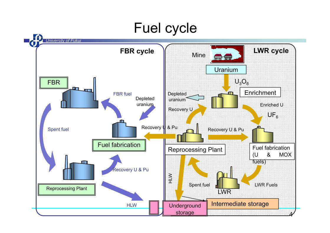
Number of neutrons produced by one fissionUniversity of Fukui
239PuWhen η is less than 2, breeding is impossiblea
fissi
on
Pu breeding is impossible.
One must be used for fi i d th th
241Pu
oduc
ed b
y
a fission, and the other one should be used for breeding.
utro
ns p
ro
Some of them escape from the reactor.
Thermal neutron Fast neutronber o
f neu
Thermal neutron Fast neutron
Num
9
Energy of neutron (eV)

Characteristics of FBRUniversity of Fukui
• FBR can produce nuclear fuel more thanFBR can produce nuclear fuel more than consumption. Configuration of FBR is different from LWRsdifferent from LWRs.
• Neutrons are not moderated in order to breed nuclear fuel efficientlybreed nuclear fuel efficiently.
• Enrichment of fuel is higher than that of fLWR in order to raise fission probability.
• Fuels should be cooled by good heat y gtransfer coolant (sodium) because power density is high.
10
y g

Comparison of reactor vessel between FBR and LWRUniversity of Fukui
Monju238MWe
Mihama Unit-3238MWe
Reactor vessel is
826MWe
Reactor vessel is thin due to low
t
vessel is thick due to highsystem
pressure
to high system pressure
11
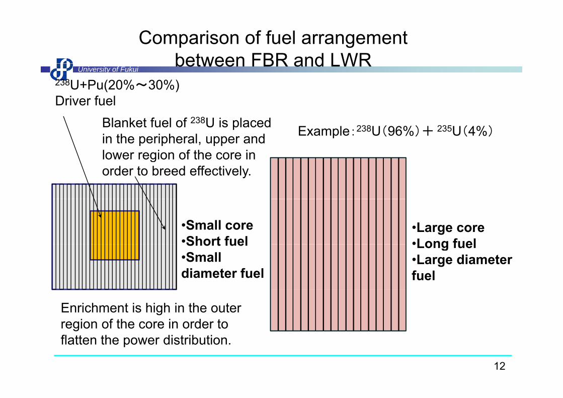
Comparison of fuel arrangementbetween FBR and LWR
University of Fukuibetween FBR and LWR
238U+Pu(20%~30%)Driver fuel
Blanket fuel of 238U is placed in the peripheral, upper and lower region of the core in
Example:238U(96%)+ 235U(4%)
lower region of the core in order to breed effectively.
•Small core•Short fuel
•Large core•Long fuelShort fuel
•Small diameter fuel
•Long fuel•Large diameter fuel
Enrichment is high in the outer region of the core in order to
12
flatten the power distribution.

Comparison of fuel assemblyUniversity of Fukui
y
Length 4 2m
Length:2.8mFeul elements:162Bl k t ll t
Length:approx. 4m Effective length:Approx. 3.6mWeight:670kg (17×17)
13
Length:4.2mBlanket pellets are inserted in the cladding.
Weight:670kg (17×17)

Comparison of turbine systemsUniversity of Fukui
13MPa483℃
p y
Main steam MSIVLow P turbine
Containment Vessel
0.8MPa
GMSIV
高圧タービン
Low P turbine
Generator
Condenserバイパス弁
DB
6.4MPa278℃Condensate pump
Control valve
Sea waterA
0.0042MPa at 30℃
Vacuum200℃
Turbine rotor
Low pressure feed-waterheaters
Feed-water pumpHigh pressure feed-waterheaters
15 7MPa
Vacuum 25℃
Feed water heaters
Generator
Control valve
Casing
Cross-over pipe
15.7MPa325℃
Casing
Main steamControl valve
Efficiency: ≈32%
14
Extraction Efficiency: ≈40%y

Rankin CycleUniversity of Fukui
TC
Critical point347.15 ℃22 1MPa
TCritical point647.3 K22.1MPa487℃
B’C’
C
LiquidSuper heated
22.1MPa
B’ C’Liq. Super heated S
280℃328℃ Higher energy
- Receive Q1
- Release Q2
Power output L
AB
DD’E
Saturation curve
Super heated steam
MixtureA
BD’
E
heated S.
Mixture~300K
- Power output L1
- Pump work L2S0
SA S’C SCS
0SA S’C
2
1
)()''(
ASADSAreaiiQBSCSCBBAreaiiQ
ACAD
ACBC
'2
'1
)''()'''(
ASSADAreaiiQBSSCBBAreaiiQ
ACAD
ACBC
2121 QQiiiiLL ABDC )''(2121 CDACABBAreaQQLL
F
21''21 QQiiiiLL ABDC )'''(2121 ADCABBAreaQQLL
L
15
)''(11 BSCSCBBAreaQQ ACF )'''(11 BSSCBBAreaQQ AC
L

FBR & LWRUniversity of Fukui
FBR LWRNeutron life time 10-7 seconds 10-5 secondsRatio of delayed neutron 0.34~0.37% 0.55~0.7%Mean free path long shortCoolant Sodium (low corrosive) Water (high corrosive)Fuel UO2,, PuO2 (Enrichment ~
20%)UO2 (Enrichment 3~4%)%) %)
Cladding S.S. ZircaloyDia. of fuel pellet 4~6mm Approx. 1cmOutlet coolant temperature
500~550℃ 280~320℃
Temperature difference 130~150℃ 15℃(B)~35℃(P)Temperature difference 130 150℃ 15℃(B) 35℃(P)System pressure Atmospheric 7MPa(B)、15MPa(P)
Power density Approx. 300kW/l Approx. 90kW/l
16
Burn-up 100,000MWd/t 30,000~60,000MWd/tEfficiency Approx. 40% Approx. 32%

Characteristics of sodiumUniversity of Fukui
◆ Sodium : alkali metal which is soft and has metallic color.Weight of sodium : 0 97 times of water at 20 ºCWeight of sodium : 0.97 times of water at 20 ºC.◆Melting point : 98ºC(97.8 ºC ).
◆Boiling point : 881.5ºC at atmospheric pressure.g p p p
Sodium is lighter than water Cut by a knife easily Liquid sodium
17
Sodium is lighter than water. Cut by a knife easily Liquid sodium

Reaction of sodium with water and airUniversity of Fukui
◆When sodium reacts with water, hydrogen gas and NaOH are produced.2Na + 2H O → 2NaOH+ H (Hydrogen)+Heat2Na + 2H2O → 2NaOH+ H2(Hydrogen)+Heat
Therefore, sodium must be separated from water.
◆Leak speed of sodium is slow due to atmospheric system pressure◆Leak speed of sodium is slow due to atmospheric system pressure. However, sodium reacts with air as shown in photos, and produces a lot of white alkali aerosol.
18

Blow-down of high-pressure and high-temperature coolant
University of Fukui
•Blow-down: Discharge of high-temperature and high-pressure light water
•ECC water injection in order to cool down the heat-up fuel
•Even a small amount of steam leak, a jet is very dangerous. This is a different point compared to a leak of sodium.
9 Aug 2004 at Mihama NPP,5 people were5 people were killed and 6 were seriously i j d
19
injured.

Sodium leak from secondary system on 8 Dec. 1995University of Fukui
Leak location IHX Reactor
EvaporatorSuper heater
Air coolerDebris of sodium from a broken thermocouple
20
Pump for secondary systemwell

Reason of superiority of Na among liquid metalNa K NaK Li Pb Bi Pb/Bi Hg
University of Fukui(70/30) (eutectic)
Melting point(℃) 97.5 62.3 40 186 327.4 271.3 125 -38.9
Boiling point(℃) 881 758 825 1317 1737 1477 1670 357Boiling point(℃) 881 758 825 1317 1737 1477 1670 357
Vapor pressure(600℃)(mmHg) 26 128 5×10⁻² 3×10⁻⁴ 6×10⁻⁴ 22(atm)Neutron absorption cross section
Thermal neutron (barns) 0.505 2.07 71 0.17 0.034 380
Fast neutron (100eV)(mb) 1.1 5(400eV) 1000 4 3 60
Half-life period 15hr. 12.5hr. 0.8sec. 3.3hr. 5days 5.5min.
Thermal conductivity 0.15 0.084 0.07 0.036 0.037 0.02
(600℃)(cal/cm/sec/℃)
Specific heat(600℃)(cal/g/℃) 0 3 0 183 1 0 0 038 0 038 0 03Specific heat(600℃)(cal/g/℃) 0.3 0.183 1.0 0.038 0.038 0.03
Density (600℃)(g/cm3) 0.81 0.7 0.47 10.27 9.66 12.2Heat transport capability 3.4 1.9 1.2 8.8 1.2 1.3 1.2 1.4
(4in.φPipe)(C.H.V./ft2℃sec.)Pumping forth (1/ρ2c3) 47 29.2 78 4.2 178 238 233 169
Price (£/ft3) 3 42 16 120 40 500 300 730
21
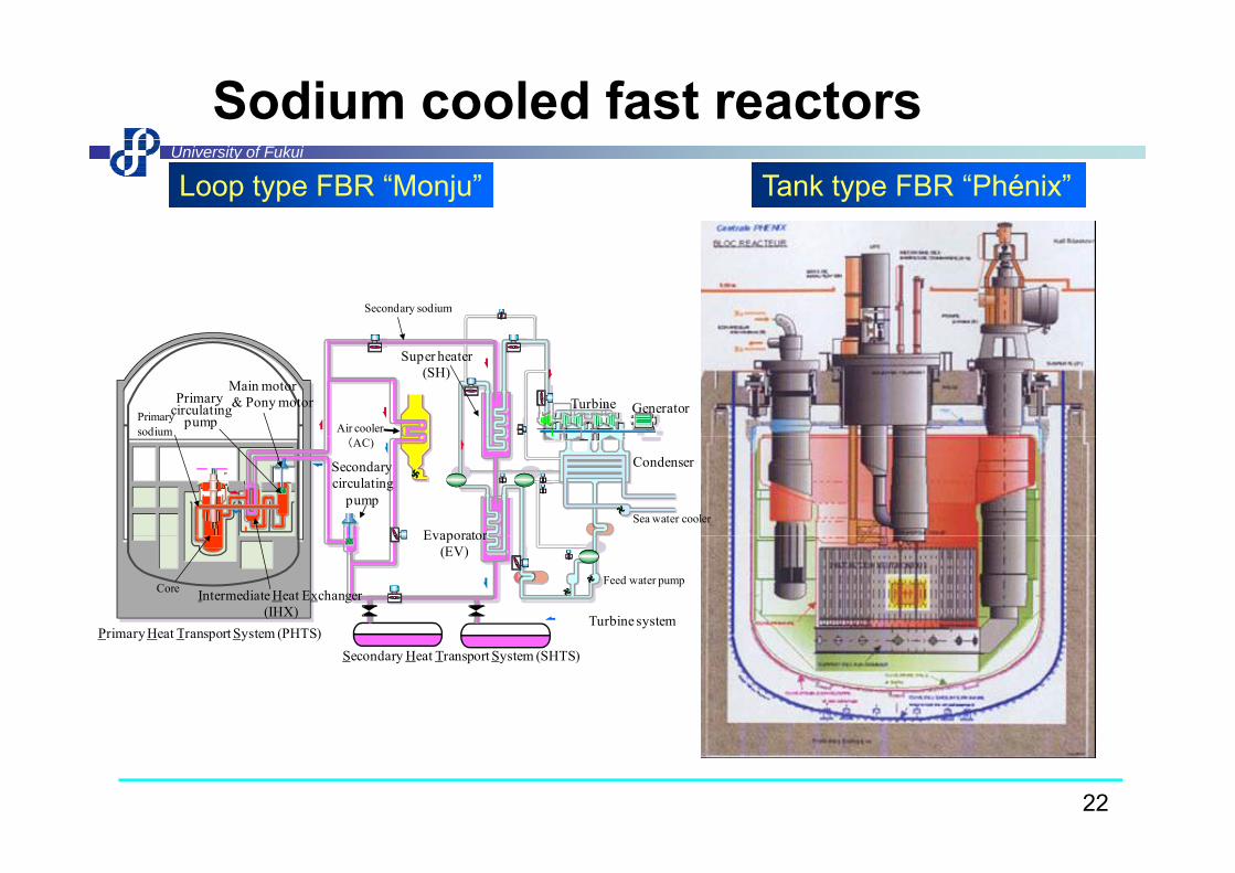
Sodium cooled fast reactorsUniversity of Fukui
Loop type FBR “Monju” Tank type FBR “Phénix”
Secondary sodium
Primarysodium
Primary circulating
pump Air cooler
Turbine Generator
Super heater(SH)
Main motor& Pony motor
(AC)
EvaporatorSea water cooler
CondenserSecondary circulating
pump
Primary Heat Transport System (PHTS)Turbine system
Intermediate Heat Exchanger(IHX)
Core
Evaporator(EV)
Feed water pump
Primary Heat Transport System (PHTS)Secondary Heat Transport System (SHTS)
22

FBR around the worldUniversity of Fukui
BN-600, 800(Belouarsk)Super Phénix (Crays-Malville)
BOR 60
DFR, PFR (Therso)
Joyo (O arai)Monju (Tsuruga)
CEFR(Beijing)
EBR-Ⅱ(Idaho falles)FFTF(Hanford)
Phénix (Marcoule)
( y )
BN-350(Aktau)
BOR-60(Dimitrovgrad)
FBTR, PFBR (Kalpakkam)
Joyo (O-arai)
( )
:Closed:in operation (including outage)
23

First power plant in the world (USA)University of Fukui
( )EBR-I (Experimental Breeder Reactor)Coolant was NaK Four light bulbs were lit up on 20 DecemberCoolant was NaK. Four light bulbs were lit up on 20 December 1951.
24

Donreay Fast Reactor, PFR (UK)University of Fukui
Rating: 60 MWt/15MWeCoolant: Na-K Loops: 24Loops: 24
Prototype Fast Reactor
25

Phénix (France)University of Fukui
Oldest power reactor in France.
Rating: 565MWt/255MWeRating: 565MWt/255MWeCoolant: NaLoops: 3
26

Tank-type FBR(Phénix)University of Fukui
yp )
27

Super-Phénix (France)University of Fukui
p ( )
Electrical power:p1200MWe
D t tiDemonstration plant in France
・Super-Phénix was sacrificed by Prime minister Jopspin on 2 February 1998 in order to have a
28coraboration between Socialist party and green party.

Super-PhénixUniversity of Fukui
Snapshots in side the plant were
p
the plant were allowed after the workshop at SPX. This might be theThis might be the first and the last chance.
29

FBTR (India)University of Fukui
40 MWt /13.2 MWeFuelFuel
Mark I ( 25 Nos.) 70% PuC + 30% UCMark II ( 13 Nos.) 55% PuC + 45% UCPFBR t t SA 29% P O 71% UO
30
PFBR test SA 29% PuO2 + 71% UO2 From IAEA-TECDOC-1531

PFBR (India)University of Fukui
( )01 Main Vessel02 Core Support Structure03 Core Catcher04 Grid Plate05 Core05 Core06 Inner Vessel07 Roof Slab08 Large Rotating Plug09 Small Rotating Plug10 C t l Pl10 Control Plug11 CSRDM / DSRDM12 Transfer Arm13 Intermediate Heat
Exchanger14 Primary Sodium Pump
31
14 Primary Sodium Pump15 Safety Vessel16 Reactor Vault

PFBR in 2008University of Fukui
32

BN600 (Russia)University of Fukui
Beloyarsk NPP is close to Ekaterinburg.
Sit f BN800 BN600
Pressure tube type reactor
Site for BN800 BN600
33

BN600University of Fukui
Modular type steam generatorIrradiation of vibro-pack fuel (Dismantled From IAEA-TECDOC-1531
34
p (War head was used.)
From IAEA TECDOC 1531

BN600University of Fukui
35From IAEA-TECDOC-1531

BN800 Construction siteUniversity of Fukui
36

CEFR(1/3)University of Fukui
( )
37

CEFR(2/3)University of Fukui
38
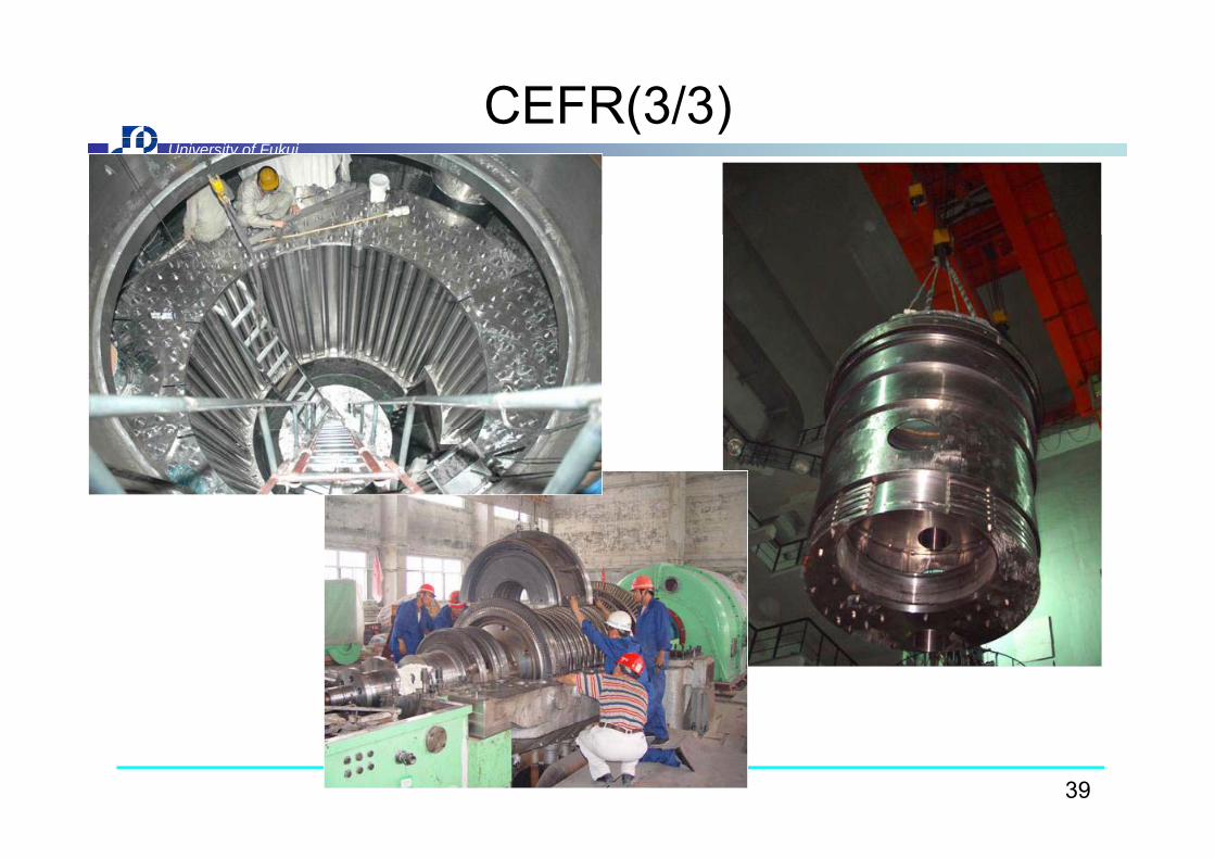
CEFR(3/3)University of Fukui
39

Core of “Monju”University of Fukui
40
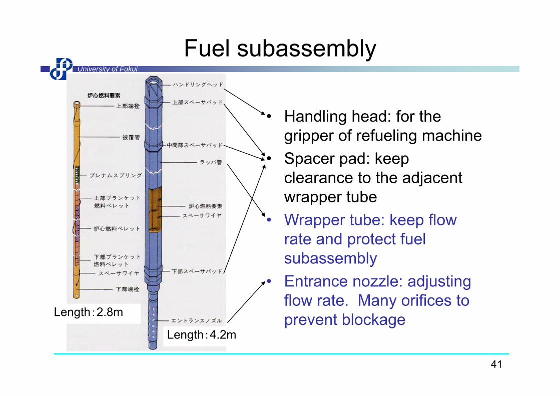
Fuel subassemblyUniversity of Fukui
• Handling head: for the gripper of refueling machineS d k• Spacer pad: keep clearance to the adjacent wrapper tubewrapper tube
• Wrapper tube: keep flow rate and protect fuelrate and protect fuel subassembly
• Entrance nozzle: adjusting j gflow rate. Many orifices to prevent blockage
Length 4 2m
Length:2.8m
41
Length:4.2m
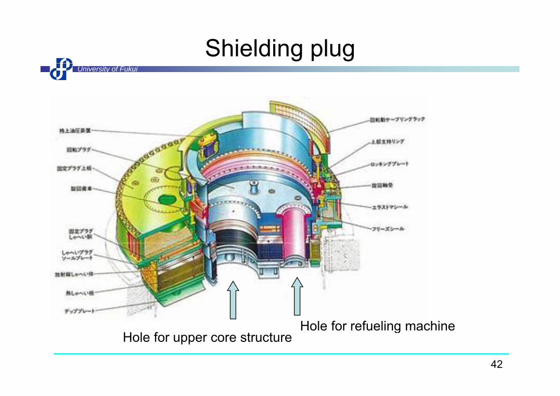
Shielding plugUniversity of Fukui
H l f t tHole for refueling machine
42
Hole for upper core structureg

UIS and refueling machineUniversity of Fukui
g
43

Arrangement of initial coreUniversity of Fukui
g
Driver fuel subassemblies(fuels for driving the core)
Blanket fuel subassemblies(fuels for breeding)
Inner core PuO 20%Inner coreOuter coreBlanket
Neutron source
PuO2 20%PuO2 25%238U
Neutron sourceCFB
CCFFBB
B4CControl rod
44
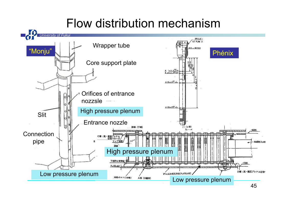
Flow distribution mechanismUniversity of Fukui
Wrapper tube“Monju” Phénix
Core support platePhénix
Orifices of entrance nozzsle
Slit
nozzsleHigh pressure plenum
Entrance nozzle
Connection pipe
Entrance nozzle
High pressure plenum
45
Low pressure plenumLow pressure plenum

Fuel subassembly of Fermi reactorUniversity of Fukui
A fuel melt accident occurred in October 1966 A part of ain October 1966. A part of a fuel structure fell down at the inlet of the fuel assembly and yblocked the entrance.
Orifices were provided in d t t t t lorder to prevent total
blockage. This is a lesson learned from the accidentlearned from the accident.
46
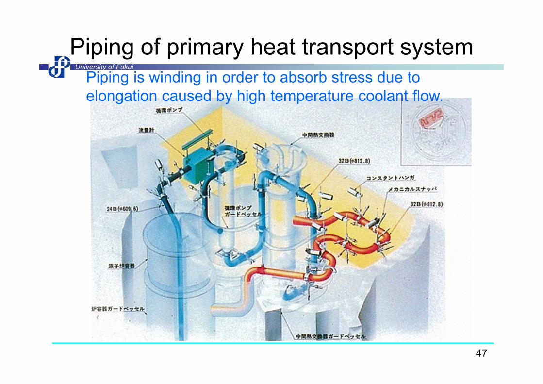
Piping of primary heat transport systemUniversity of Fukui
Piping is winding in order to absorb stress due to elongation caused by high temperature coolant flow.
47

Intermediate heat exchangerUniversity of Fukui
gInlet of secondary sideOutlet of secondary side
Primary Secondary
Fl t 5120t/h 3730t/hFlowrate 5120t/h 3730t/hInlet temp. 529℃ 325℃
Outlet temp 397℃ 505℃Outlet temp. 397℃ 505℃
Configuration of heat
OD 21.7mm, thickness:1.2mm,
Approx. 6mApprox.12m
transfer tube,
length:6.07mNumber of HT tubes
3294Inlet of primary side
HT tubesRating 238MWHeight 12 1m O tl t f i id
48
Height 12.1m Outlet of primary side

Heat transfer in IHXUniversity of Fukui
100Inlet of secondary sideOutlet of secondary side
10 [1] Seban & Shimazaki
(Nu=5+0.025Pe0.8)[1]
[3]
1 Nu(1) 50MWSG
Nu
(Nu 5 0.025Pe )
[2] Martinelli & Lyon
(Nu=7+0.025Pe0.8)[3] Lubarsky & Kaufman (Nu=0.625Pe0.4)
[1]
Approx. 6mApprox.12m
0 1
Nu(1) JoyoNu(1) MonjuNu(2) 50MWSGNu(2) JoyoNu(2) MonjuSeban-Shimazaki
Inlet of primary side
0.11 10 100 1000 104 105
Pe Outlet of primary side
49

CFD analysis of IHXUniversity of Fukui
yRectifying mechanism
Small holes more than 13000 are meshed at present.
Inlet window
Inlet windows
p
Plate
#1
#2 Rectifying plateSmall holes
Nozzle #3
#4
#5
Inletwindow
Rectifying plate holes
小孔#5
#6
#7 Plates
Inlet of primary sodium
Outlet of primary
(7)
Outleti d
Bank of heat transfer tubes
Shell
50
primary sodium window

Analysis using 60°sector modelUniversity of Fukui
①
②
③
y gHeat transfer tubes
Secondary outletPlate
10% flowrate
④
⑤
⑥
#1
#2
Primaryinlet
Inlet window #3
#4
#50.1
Velocity480
Temp.
OutletFlowrateratio
#6
#70 325Outlet
window 1.0
0.5
ratio
Primary
#7 m/s325℃
Secondary
51M. Takano and H. Mochizuki, CFD Flow Pattern Analysis on Primary-side of IHX for Fast Reactors, ICONE-19, 43412, Chiba, Japan (2011).
0.0 outletSecondary inlet

Internals of IHXUniversity of Fukui
52
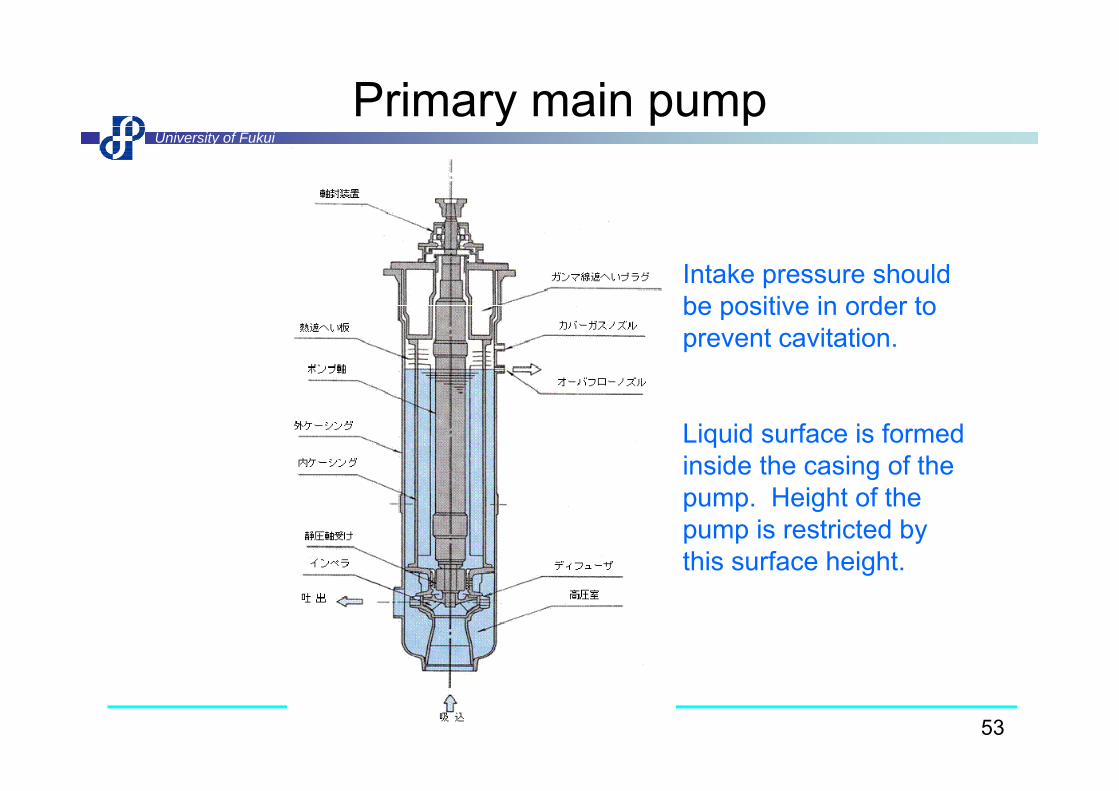
Primary main pumpUniversity of Fukui
y
Intake pressure should be positive in order tobe positive in order to prevent cavitation.
Liquid surface is formed inside the casing of the pump. Height of the pump is restricted by this surface height. g
53
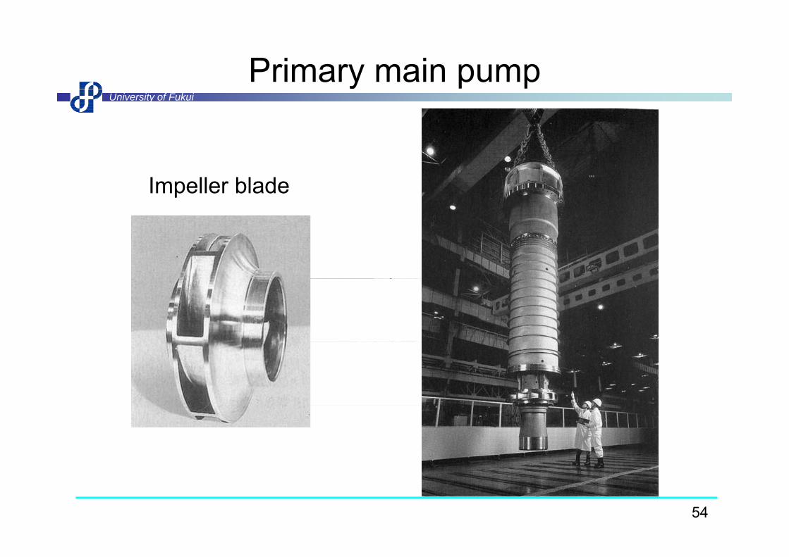
Primary main pumpUniversity of Fukui
y
Impeller blade
54
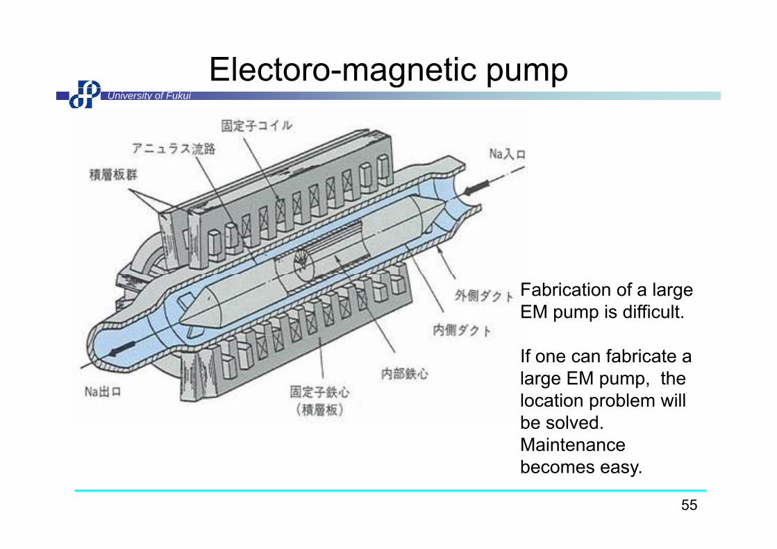
Electoro-magnetic pumpUniversity of Fukui
g
Fabrication of a large EM pump is difficult.
If one can fabricate a large EM pump, the location problem willlocation problem will be solved. Maintenance b
55
becomes easy.

Steam generatorUniversity of Fukui
g
140 heat transfer tubes are coiled.
56
140 heat transfer tubes are coiled.

Super heater used at 50MW SG facilityUniversity of Fukui
Sodium flow
Inner ductHelically coiled heatHelically coiled heat transfer tube
Water flow
57

Air cooler for auxiliary systemUniversity of Fukui
Outlet damperDesign: 15MW, Real rating :20MW
Outlet damper(controlled with inlet vanes)
Approx. 30m Heat transfer tubes with fins30m
~4.5m ~5.3m
~6.5m
I l t d
Inlet vanes
Inlet damper
58Blower

H.T. C. of Finned Heat Transfer TubeUniversity of Fukui
ehdN CopperCarbon S.1000
50 MWSG
a
e
kNu Turbulent
ppS. S.
100
MonjuJoyo
Data by Jameson
+10%-10%
10Pr1/
3 Nu/Pr1/3=0.1370Re0.6702
Data by Jameson
Laminar
10
Nu/
P
1+20%
N /P 1/3 9 796 10 -3R 0 9881
0.110 100 1000 104 105
-20%Nu/Pr1/3=9.796 10 3Re0.9881
×
59
10 100 1000 10 10Re
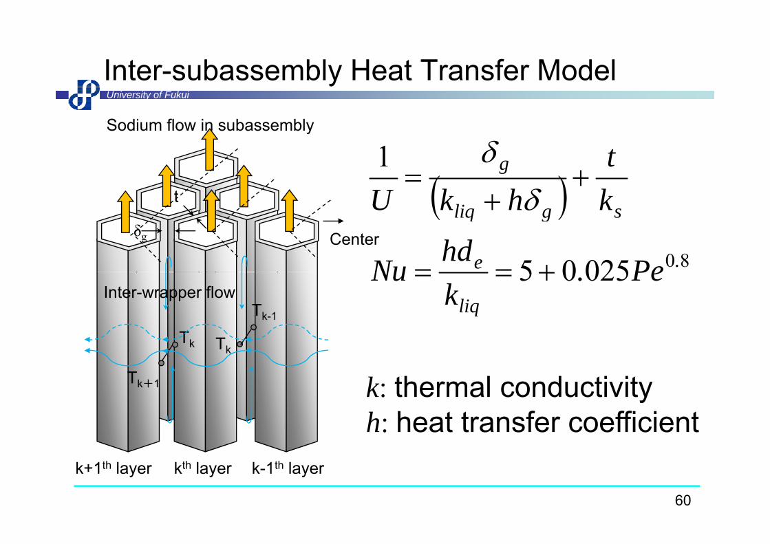
Inter-subassembly Heat Transfer ModelUniversity of Fukui
Sodium flow in subassembly
1 t
1
sgliq
g
kt
hkU
Centerδg
8002505 .e
sgliq
PehdNu
U
TTk-1
Inter-wrapper flow02505
liqPe.
kNu
Tk
Tk+1
Tk
k: thermal conductivityk: thermal conductivityh: heat transfer coefficient
60
k+1th layer k-1th layerkth layer

Heat Transfer to the Concerned ChannelUniversity of Fukui
j jjjjnj TTUlNQ 6Tn,i
j
Tmj
Layer k+1
To ij
jm
ji,n
jmi
ji,m
jm TTUzlNQ 1
d i l h
Tm
Layer k
To,i
j: concerned axial meshm: concerned channel groupl idth f h l t b
Layer k
l: width of hexagonal wrapper tubezj: length of mesh j
b f b bli fNmn
,i: number of subassemblies of channel group n facing to the face i
f h l61
of channel m

Exit temperature of 3rd Layer SubassemblyUniversity of Fukui
560
SSC-L520
540)
40℃SSC L
500
re (
deg-
C )
ure
(℃)
Measured460
480
empe
ratu
rTe
mpe
ratu
420
440
NETFLOW++ ith ISHT d l
Te T
400
420
0 50 100 150 200 250 300 350 400
NETFLOW++ with ISHT modelNETFLOW++ without ISHT model
62
0 50 100 150 200 250 300 350 400
Time (sec)

Downsizing of FBRUniversity of Fukui
Volume of reactor building= 810 000 m3 810,000 m
Prototype FBR “Monju”
Gen-IV FBR (JSFR)
Prototype FBR MonjuThermal output 714 MWt
Electrical output 280 MWeGen-IV FBR (JSFR)
Thermal output 3570 MWtElectrical output 1500 MWe
63

Combined IHX and pumpUniversity of Fukui
MotorPump support
primary outprimary inprimary in
secondary out BellowsNSSS
DHX
IHX heat transfer t b
DHX
IHX support
Pump can be withdrawn.
64Pump
tubessecondary in

IAEA benchmark problems #1) Natural circulation test at Phenixand #3) LOF&ULOF tests at EBR-II
University of Fukui
IHX Inlet temp. Mochizuki Lab. was only i ti i J dIHX Inlet temp. organization in Japan and
only university in the world who participated in the calculation.
The benchmark
calculation.
1
input deck was created on the basis of plant configuration and
IHX Outlet temp.
0.1
Measured
Calculated
d flo
wra
te (-
)
configuration and fuel patterns of EBR-II. Now this analysis a kind of
Our result is at the midst of the calculation curves
Flow rate change
0.010 200 400 600 800 1000
Nor
mal
ized blind test. However
left result was presented in an international
65
0 200 400 600 800 1000
Time (sec)international conference.
H. Mochizuki, N. Kikuchi and S. Li, Calculation of Natural Convection Test at Phénix using the NETFLOW++ Code, Proceeding of International Congress on Advances in Nuclear Power Plant (ICAPP 2012), Chicago, Paper 12104, USA, (2012-June).
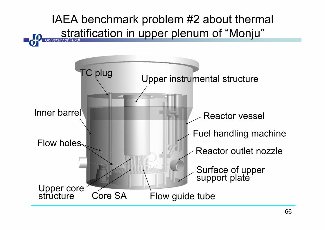
IAEA benchmark problem #2 about thermal stratification in upper plenum of “Monju”
University of Fukuistratification in upper plenum of Monju
Upper instrumental structure TC plug
Inner barrel Reactor vessel
Fuel handling machineFl h l
Inner barrel Reactor vessel
Reactor outlet nozzleFlow holes
S f f
Fl id t bC SA
Surface of upper support plate
Upper core t t
66
Flow guide tubeCore SAstructure

Overall view of the CAD modelUniversity of Fukui
m m4.
38 m
5.30
m
Upper flow-holes(24)
Lower flow-holes(48)( )
67

CAD model around UCSUniversity of Fukui
UISUIS
Control rod
Honeycombstructure
guide tube
Flow guideguide tube
68

Tetrahedral meshes in the plenumUniversity of Fukui
33 illi i d t t h d l h69
33 million prism and tetrahedral meshes

Configuration of the reactor core at the testUniversity of Fukui
g
Inner core 108 Outer core 90
IAEA ClassificationCh. 1-5Ch. 6-8
Blanket 172Neutron shield 324 Neutron source 2Control rod (Coarse) 10Control rod (Fine) 3
Ch.9-11Ch.12,13 and FCCh. NCh. CCh F
70
Control rod (Fine) 3Control rod (Back-up) 6
Ch. FCh. B
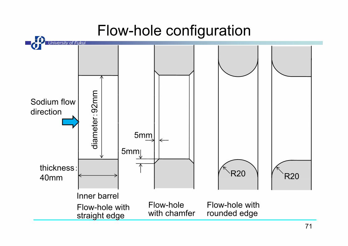
Flow-hole configurationUniversity of Fukui
mer:92
mm
Sodium flowdirection
diam
ete
5mm
5mm
5mm
thickness:40mm R20 R20
Inner barrelFlow hole with
40mm
Flow-hole Flow-hole with
R20
71
Flow-hole with straight edge
Flow hole with chamfer
Flow hole with rounded edge

Results with boundary conditions calculated by 1D codeand with rounded edge
University of Fukuig
Mesh configuration for flow-holes with boundary layers0
0 sec 0 secMeasured Computed
-2000
-1000
0 sec601203006001200
0 sec601203006001200
m)
-4000
-3000
Ele
vatio
n (m
m
-6000
-5000
72
360 380 400 420 440 460 480 500-7000
Temperature (oC)

Contour maps from 0 sec to 20 min.University of Fukui
(m/s)1.0
0.5
00
Evolution of velocity distribution in the upper plenum0 300 600 1200 secEvolution of velocity distribution in the upper plenum
(ºC)510
435
360
E l i f di ib i i h l0 300 600 1200 sec
73
Evolution of temperature distribution in the upper plenum


![Baku-Baku弁当 - ごちクルBaku-Baku弁当 [ 2 / 3 ] 2020年06月15日現在 特製トマトソースハンバー グ弁当 695円(税込750円)/品番:SFIZ025 おにぎり焼肉弁当](https://img.pdfslide.us/doc/110x75/5f136d4ad7351e15a961580a/baku-baku-f-baku-baku-2-3-202006oe15coe.jpg)

![HUD[Heads Up Display=情報表示装置] - sts-japan.com · プレッシャデマンド形空気呼吸器(自動陽圧切替型)ライフゼム a1-12 バイパス弁 陽圧ロックレバー](https://img.pdfslide.us/doc/110x75/5dd08622d6be591ccb6167c5/hudheads-up-displayifecec-sts-japan-fffffffffcieeoeifff.jpg)