Embed Size (px)
Citation preview

1
VNM Recorder • Setup GuideThe Extron VNM Recorder is a network storage device used to digitally record and play back multiple streams of high resolution video, audio, and data encoded to an IP network via VN-Matrix encoders and decoders. It can be used with any VN-Matrix application to document, archive, review, and play back highly sophisticated or demanding AV imagery.
This guide provides basic instructions for an experienced installer to configure and operate a VNM Recorder using a basic VN-Matrix system.
NOTE: See the VNM Recorder User Guide, VN-Matrix 200 Series User Guide, VN-Matrix 225 Series User Guide, VN-Matrix 300 User Guide, and the VN-Matrix 325 User Guide for complete installation, network configuration, and mounting information. User guides are available at www.extron.com.
Initial Installation and Configuration of Devices
Step 1 — Determine the Default Network SettingsBefore connecting any device to a network, the default network settings of each device must be changed. On an existing network, check with the network administrator for a range of available IP addresses.
On a closed network, used exclusively for VN-Matrix devices, it is recommended to use addresses within the range of 192.168.254.1 to 192.168.254.254 with a subnet mask of 255.255.255.0.
Figure 1 shows an example addressing scheme for a simple system that contains a VNM Recorder, an encoder, and a decoder.
Step 2 — Determine the Device that Acts as the ControllerA device within the VN-Matrix system must be designated as the controller of the network. The controller can be one of the following devices:
z VN-Matrix 200, 225, 300, or 325 device, which is suitable for small network systems
z VNM Recorder, which is suitable for small network systems
z VNM Enterprise Controller, which is suitable for large network systems
The controller device acts as a central point of reference for each device, manages all of the system communications to every matrix device present, and also serves the web-based control interface to the user. In figure 1, the VNM Recorder is set up as the controller for the system. Once configuration of the VN-Matrix system is complete, the IP address of the controller device can be entered into a suitable web browser running on any PC or laptop connected to the VN-Matrix network.
Step 3 — Install and Configure the VN-Matrix 200 / 225 / 300 / 325 DevicesConnect these devices as necessary and power them on. Configure the network settings of these devices using a PC running HyperTerminal. For installation and configuration instructions, see the setup guides included with these devices. Figure 1 can also be used as a guide for configuring network settings.
Step 4 — Connect the Recorder to the VN-Matrix NetworkWith the VNM Recorder positioned as shown in figure 1, connect the primary VN-Matrix network to the upper Ethernet connector (eth0) of the recorder using Category (CAT) 6 cable. If necessary, connect a secondary VN-Matrix network to the lower Ethernet connector (eth1) of the recorder using CAT 6 cable.
Step 5 — Connect Configuration Devices to the RecorderConnect a mouse, a keyboard, and a computer monitor to the recorder. See the VNM Recorder User Guide for more information on connecting these devices.
Step 6 — Power on the RecorderPlug a standard IEC power cord into the recorder and connect it to a power source. Power on the recorder.
LAN -1LAN -2STATUS
RGB/DVI OVER IPVN-MATRIX 200 SERIES
LAN -1LAN -2STATUS
RGB/DVI OVER IPVN-MATRIX 200 SERIES
PC (source) DisplayVNM 200 (encoder)
Local IP Address: 192.168.254.101Controller IP Address: 192.168.254.254
Local IP Address: 192.168.254.102Controller IP Address: 192.168.254.254
Local IP Address: 192.168.254.254Controller IP Address: 192.168.254.254
VNM 225 (decoder)Local NetworkSwitch
VNM Recorder (system controller)
RGBor
DVI DVIEthernet
RS-232 RS-232
Ethernet
Ethernet
EthernetBrowser UserControl
Figure 1. Example VN-Matrix Network Configuration
Lower connector (eth1)
Upper connector (eth0)

2
VNM Recorder • Setup Guide (Continued)
Step 7 — Configure the VNM Recorder Network SettingsThe VNM Recorder is pre-configured with the following network settings:
IP address: 192.168.254.254 Subnet mask: 255.255.255.0
NOTE: Using these settings, the VN-Matrix 200 / 225 / 300 / 325 devices must use IP addresses within the range of 192.168.254.1 through 192.168.254.253 and use the same subnet mask. The example in figure 1 uses the default settings of the VNM Recorder.
Use the following procedure to change the network settings of the VNM Recorder, if necessary.
a. Enter the administrator username and password at the VNM Recorder login screen.
NOTES: • The login screen appears shortly after powering on the VNM Recorder.
• The default username is root. The default password is Extron2010. These entries are case sensitive.
b. From the desktop, select System > Administration > Network. The Network Configuration window appears (see figure 2).
c. Select the eth0 (upper Ethernet connector) device line to highlight it. The status should read Active.
d. Click on Deactivate. The status of the eth0 device should now read Inactive.
e. Double-click on the eth0 device line. The Ethernet Device window appears (see figure 3).
f. Change the Address and Subnet mask fields as required and then click OK.
NOTE: The Default gateway address field is only required if devices are on different subnets.
g. Navigate back to the Network Configuration window (see step 7b). Select the eth0 device and then click Activate.
h. If changes were made, a prompt appears asking to confirm the changes. Click Yes to confirm and save the changes.
i. Another window appears. Click OK to continue.
j. A loading window appears and the necessary changes are made to the system. After the loading window disappears, navigate back to the Network Configuration window and check that the status of the eth0 device now reads Active.
k. Close the Network Configuration window.
Step 8 — Configure the VNM Recorder Controller SettingsUse the following procedure to setup the VNM Recorder to use the IP address of the controller device.
a. If necessary, enter the administrator username and password at the VNM Recorder login screen (see step 7a).
b. From the desktop, double-click on Computer > Filesystem > home > matrix_rec.
c. Double-click on the folder that contains the latest release of the recorder software (at the time this guide was released, the latest software would be stored in the V3.10.9 folder or in a folder with a similar name).
d. Click on the config.xml file to select it.
e. From the Edit menu, select Duplicate. This creates a backup copy [ named config (copy).xml ] of the original config.xml file. Keep the backup copy for system restoration purposes.
f. Right-click on the config.xml file and select the Open with “Emacs Text Editor” option.
Figure 2. Network Configuration Window
255.255.255.0
192.168.254.254
Figure 3. Ethernet Device Window
3
3
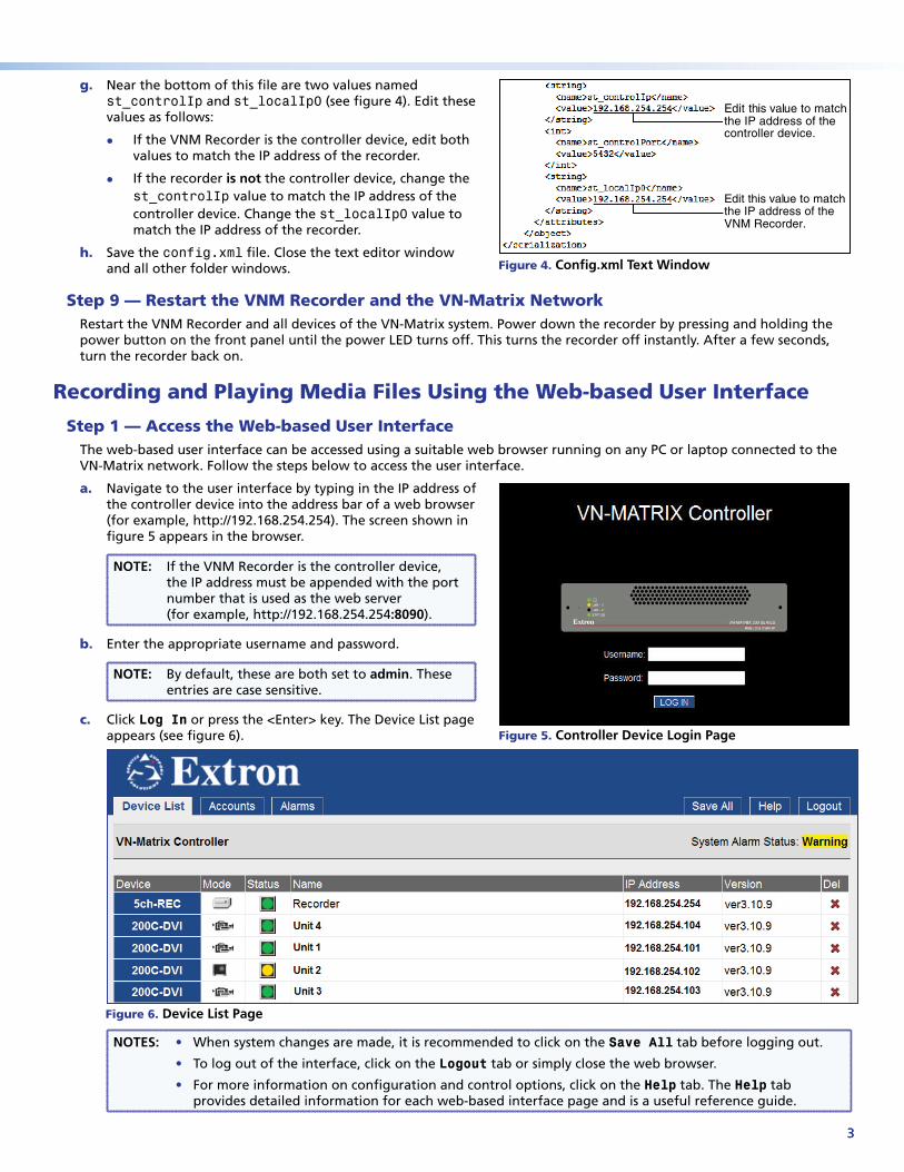
g. Near the bottom of this file are two values named st_controlIp and st_localIp0 (see figure 4). Edit these values as follows:
z If the VNM Recorder is the controller device, edit both values to match the IP address of the recorder.
z If the recorder is not the controller device, change the st_controlIp value to match the IP address of the controller device. Change the st_localIp0 value to match the IP address of the recorder.
h. Save the config.xml file. Close the text editor window and all other folder windows.
Step 9 — Restart the VNM Recorder and the VN-Matrix NetworkRestart the VNM Recorder and all devices of the VN-Matrix system. Power down the recorder by pressing and holding the power button on the front panel until the power LED turns off. This turns the recorder off instantly. After a few seconds, turn the recorder back on.
Recording and Playing Media Files Using the Web-based User Interface
Step 1 — Access the Web-based User InterfaceThe web-based user interface can be accessed using a suitable web browser running on any PC or laptop connected to the VN-Matrix network. Follow the steps below to access the user interface.
a. Navigate to the user interface by typing in the IP address of the controller device into the address bar of a web browser (for example, http://192.168.254.254). The screen shown in figure 5 appears in the browser.
NOTE: If the VNM Recorder is the controller device, the IP address must be appended with the port number that is used as the web server (for example, http://192.168.254.254:8090).
b. Enter the appropriate username and password.
NOTE: By default, these are both set to admin. These entries are case sensitive.
c. Click Log In or press the <Enter> key. The Device List page appears (see figure 6).
NOTES: • When system changes are made, it is recommended to click on the Save All tab before logging out.
• To log out of the interface, click on the Logout tab or simply close the web browser.
• For more information on configuration and control options, click on the Help tab. The Help tab provides detailed information for each web-based interface page and is a useful reference guide.
Edit this value to matchthe IP address of thecontroller device.
Edit this value to matchthe IP address of theVNM Recorder.
Figure 4. Config.xml Text Window
Figure 5. Controller Device Login Page
Figure 6. Device List Page

4
VNM Recorder • Setup Guide (Continued)
Extron Headquarters
+1.800.633.9876 (Inside USA/Canada Only)
Extron USA - West Extron USA - East +1.714.491.1500 +1.919.863.1794 +1.714.491.1517 FAX +1.919.863.1797 FAX
Extron Europe
+800.3987.6673 (Inside Europe Only)
+31.33.453.4040 +31.33.453.4050 FAX
Extron Asia
+800.7339.8766 (Inside Asia Only)
+65.6383.4400+65.6383.4664 FAX
Extron Japan
+81.3.3511.7655+81.3.3511.7656 FAX
Extron China
+4000.398766 Inside China Only
+86.21.3760.1568 +86.21.3760.1566 FAX
Extron Middle East
+971.4.2991800+971.4.2991880 FAX
Extron Korea
+82.2.3444.1571+82.2.3444.1575 FAX
Extron India
1800.3070.3777 Inside India Only
+91-80-3055.3777 +91 80 3055 3737 FAX
© 2012 Extron Electronics — All rights reserved. All trademarks mentioned are the property of their respective owners. www.extron.com 68-1998-50 Rev. B 02 12
Step 2 — Configure the VN-Matrix 200 / 225 / 300 / 325 Devices as Encoders or DecodersFor the VNM Recorder to work properly, the VN-Matrix 200 / 225 / 300 / 325 devices must be configured so that at least one device is an encoder and one device is a decoder. For configuration instructions for the VN-Matrix 200 / 225 / 300 / 325 devices, see the setup guides included with these devices.
Step 3 — Setup a Stream Storage Locationa. From the Device List page (see figure 6 on page 3), click the VNM Recorder device. The Device page appears.
b. From the Device page, click the Recorder icon. The Recorder page appears.
c. From the Recorder page, click the Navigate tab. The Navigate page appears.
d. Using the Content Directory at the bottom of the Navigate page, navigate to the folder where recorded media files will be stored. Click Update Storage Path to set the selected folder as the storage location.
NOTE: To create a new directory, navigate to the location where the recorded media streams will be stored and type in the name of the directory in the box to the right of the Make Directory button. Click Make Directory to create the directory.
e. Click the Save All tab. The VNM Recorder is now ready to record and play back media files.
Recording a Stream1. From the Device List page (see figure 6 on page 3), click the VNM Recorder device. The Device page appears.
2. From the Device page, click the Recorder icon. The Recorder page appears (see figure 7).
3. Using the source drop-down menus, choose the VN-Matrix encoder device that will be recorded from.
4. To record an associated audio stream, check the audio box. The ability to record associated whiteboard (wb) or data (data) streams can also be checked if these functions are available on the source.
5. Enter a filename for the stream and an optional description.
6. To start recording, check the record box and click Update.
7. To stop recording, uncheck the record box and click Update.
NOTE: Recording does not actually start or stop until Update is clicked.
Playing and Viewing a Recorded Stream1. From the Device List page (see figure 6 on page 3), click the
decoder device. The Device page appears.
2. From the Device page, click the display icon. The Display page appears (see figure 8).
3. Select a recorder channel from the Source drop-down menu and click Update to set the source device.
4. From the Device List page (see figure 6 on page 3), click the VNM Recorder device. The Device page appears.
5. From the Device page, click the Player icon. The Player page appears.
6. In the Listing section, click on the media file that will be played back. The media file appears on channel 1.
7. Click Play to view the media file. Use the various playback buttons to control playback of the media stream.
Figure 8. Selecting and Updating the Source of the Decoder
Figure 7. Recorder Page Configuration