Embed Size (px)
Citation preview
DEPARTMENT OF THE AIR FORCE AIR FORCE CIVIL ENGINEER CENTER
20 MAY 2013 FROM: AFCEC/DD 139 Barnes Drive Suite 1 Tyndall AFB FL 32403-5319 SUBJECT: Engineering Technical Letter (ETL) 13-2: Design, Construction,
Operations, and Maintenance of Semi-permanent Wastewater Treatment Plants at Contingency Locations
1. Purpose. This ETL is a guidance document for use in contingency locations or deployed locations outside the United States that require semi-permanent wastewater treatment facilities (WWTF) for 30 to 250 personnel. Guidance exists for initial and temporary facilities (less than 24 months) and for permanent facilities, but not specifically for small contingency locations (30 to 250 personnel). This ETL provides an intermediate step to the methods covered in Air Force pamphlet (AFPAM) 10-219V7, Expedient Methods, and Unified Facilities Criteria (UFC) 3-240-02, Domestic Wastewater Treatment. This ETL presents an approach to design, construction, and operation of treatment systems that provides optimal long-term performance, limits negative effects on local resources, and promotes sustainable water management. Note: Use of the name or mark of a specific manufacturer, commercial product, commodity, or service in this ETL does not imply endorsement by the Air Force. 2. Application: Contingency locations with a population of 30 to 250 personnel that do not have access to local sewer collection or treatment systems.
2.1. Authority: • UFC 3-230-02, O&M: Water Supply Systems • Air Force policy directive (AFPD) 32-10, Installations and Facilities • AFPD 10-2, Readiness • Air Force instruction (AFI) 10-210, Prime Base Engineer Emergency Force
(BEEF) Program • AFI 10-211, Civil Engineer Contingency Response Planning • AFI 32-1067, Water Systems
2.2. Effective Date: Immediately
2.3. Intended Users:
• Major command (MAJCOM) engineers and readiness/deployment managers • Base civil engineers (BCE)
2.4. Coordination:
APPROVED FOR PUBLIC RELEASE: DISTRIBUTION UNLIMITED

• MAJCOM/A7 (Installations and Mission Support, Readiness) • Air Force Civil Engineer Center, Readiness Directorate (AFCEC/CX) • Air Force Institute of Technology (AFIT)
3. Acronyms and Glossary. See Attachment 2, Acronyms and Glossary. 4. References. See Attachment 3, References. 5. Design and Construction of Onsite Wastewater Treatment Facilities. See Attachment 1, Design and Construction of Onsite Wastewater Treatment Facilities. 6. Point Of Contact. Questions or comments about this ETL are encouraged and should be directed to the Water and Wastewater Subject Matter Expert, AFCEC/COSC, DSN 523-6465, commercial (85) 283-6465, [email protected]. DAVID L. REYNOLDS, Colonel, USAF 4 Atchs Deputy Director 1. Design and Construction of Onsite
Wastewater Treatment Facilities 2. Acronyms and Glossary 3. References 4. Distribution List
2
DESIGN AND CONSTRUCTION OF ONSITE WASTEWATER TREATMENT FACILITIES
TABLE OF CONTENTS A1.1. INTRODUCTION ............................................................................................................................. 8
Figure A1.1. WWTF Planning and Selection Matrix ........................................................................... 11
A1.2. PUBLIC HEALTH RISKS ASSOCIATED WITH UNTREATED WASTEWATER................. 14
A1.2.1. CONSTITUENTS OF DOMESTIC WASTEWATER ......................................................... 14
A1.2.2. INTERNATIONAL GUIDANCE FOR SANITATION AND HEALTH ................................ 14
A1.3. SITE EVALUATION ....................................................................................................................... 14
Figure A1.2. Site Layout Conventional Septic System ....................................................................... 17
Figure A1.3. Site Layout Lagoon System ............................................................................................. 18
A1.3.1. CLIMATE ................................................................................................................................. 19
A1.3.2. TOPOGRAPHY AND GEOLOGY ........................................................................................ 19
A1.3.3. SOIL CHARACTERISTICS ................................................................................................... 19
A1.3.3.1. Soil Composition.............................................................................................................. 19
Figure A1.4. Soil Types ........................................................................................................................... 20
Figure A1.5. Soil Mottling ........................................................................................................................ 21
Figure A1.6. Soil Mottling In Wetland .................................................................................................... 21
A1.3.3.2. Site Testing ...................................................................................................................... 22
Figure A1.7. Soil Testing Plan ................................................................................................................ 23
Figure A1.8. Observation Pit for Leaching Area .................................................................................. 24
Figure A1.9. Percolation Test ............................................................................................................. 25
Table A1.1. Recommended Design Loading Rates Based on Percs and Soil Class gpd/sf (cm/day) ..................................................................................................................................................... 27
Table A1.2. Hydraulic/Organic Loading Rates for Infiltration Surfaces ........................................... 28
A1.3.4. GROUNDWATER AND SURFACE WATER FEATURES ............................................... 29
A1.3.4.1. Water Table or Saturated Zone Elevation ................................................................... 29
Figure A1.10. Groundwater Zones ........................................................................................................ 29
A1.3.4.2. Hydraulic Loading Limitations ....................................................................................... 30
A1.3.4.3. Groundwater and Surface Water Protection ............................................................... 30
Atch 1
(1 of 145)
A1.3.5. FLOODPLAINS ....................................................................................................................... 30
A1.4. DESIGN CONSIDERATIONS FOR TREATMENT SYSTEM SELECTION .......................... 30
A1.4.1. WASTEWATER CHARACTERISTICS; FLOW, COMPOSITION ................................... 30
Table A1.3. Wastewater Flow Estimates .............................................................................................. 31
Table A1.4. Untreated Domestic Wastewater Characteristics .......................................................... 33
A1.4.2. WATER QUALITY STANDARDS APPLICABLE TO STREAM OR SURFACE WATER DISCHARGE ......................................................................................................................................... 34
A1.4.3. WATER QUALITY STANDARDS APPLICABLE TO SUBSURFACE/GROUNDWATER DISCHARGE ........................................................................... 34
A1.4.4. CHARACTERISTICS OF RECEIVING SITE ..................................................................... 35
Table A1.5. Selected Effluent Quality Requirements ......................................................................... 35
Table A1.6. Effluent Quality Comparison of Treatment Alternatives ................................................ 36
A1.5. TREATMENT SYSTEM ALTERNATIVES ................................................................................. 37
The described alternatives may or may not be practical or otherwise allowed at a particular site because of legal, operational, or practical (e.g., natural terrain) factors. ........................................ 37
A1.5.1. SEPTIC SYSTEMS - REFERENCE GUIDE ............................................................................................. 37
Figure A1.11. Septic System with Leaching Field ............................................................................... 37
Table A1.7. Septic System Key Selection Factors .............................................................................. 37
Table A1.8. Septic System Advantages/Disadvantages .................................................................... 38
Figure A1.12. Process Flow Diagram ................................................................................................... 38
A1.5.2. CONVENTIONAL SEPTIC SYSTEMS ................................................................................ 38
Figure A1.13. Single Compartment Septic Tank ................................................................................. 39
Figure A1.14. Effluent Filter .................................................................................................................... 40
A1.5.2.1. Septic Tank Function and Treatment ........................................................................... 40
A1.5.2.2. Septic Tank Design and Sizing Criteria ....................................................................... 40
Figure A1.15. Septic Tank Design ......................................................................................................... 46
A1.5.2.3. Leaching Field Sizing and Design Arrangements ...................................................... 47
Figure A1.16. Distribution Box................................................................................................................ 48
Figure A1.17. Leaching Trench and Lateral ......................................................................................... 49
Figure A1.18. Orifice Shields .................................................................................................................. 49
Figure A1.19. Leaching Field Design .................................................................................................... 51
Figure A1.20. Leaching Field Section A ............................................................................................... 51
Atch 1
(2 of 145)
Figure A1.21. Leaching Field Installation ............................................................................................. 52
Figure A1.22. Distribution Arrangement ............................................................................................... 52
A1.5.2.4. Equipment List ................................................................................................................. 54
A1.5.3. FACULTATIVE LAGOONS – REFERENCE GUIDE ............................................................................... 56
Figure A1.23. Facultative Lagoon .......................................................................................................... 56
Table A1.11. Facultative Lagoon Key Selection Factors ................................................................... 56
Table A1.12. Facultative Lagoon Advantages/Disadvantages ......................................................... 57
Figure A1.24. Process Flow Diagram ................................................................................................... 57
A1.5.4. LAGOON SYSTEMS ............................................................................................................. 57
Figure A1.25. Aerated Lagoon with Secondary Pond ........................................................................ 59
Figure A1.26. Facultative Lagoon .......................................................................................................... 60
Figure A1.27. Profile of Lagoon Zones ................................................................................................. 61
A1.5.4.1. Operation and Sizing ...................................................................................................... 61
Table A1.13. Areal Loading Rates ......................................................................................................... 62
A1.5.4.2. Selecting Type and Discharge Arrangement .............................................................. 63
A1.5.4.3. Lining and Maintenance Requirements ....................................................................... 64
A1.5.4.4. Construction Guidelines ................................................................................................. 64
Table A1.14. Boundary Distances to Lagoons .................................................................................... 65
Figure A1.29. Component Overview Facultative Lagoon .................................................................. 66
Figure A1.30. Lagoon Profile .................................................................................................................. 67
A1.5.4.5. Maintenance Requirements ........................................................................................... 67
A1.5.4.6. Equipment List ................................................................................................................. 68
Table A1.15. Lagoon System Materials and Equipment List............................................................. 69
A1.5.5. SAND FILTERS – REFERENCE GUIDE ................................................................................................ 70
Figure A1.31. Sand Filters ...................................................................................................................... 70
Table A1.16. Sand Filters Key Selection Factors ................................................................................ 70
Table A1.17. Sand Filters Advantages/Disadvantages ...................................................................... 71
Figure A1.32. Process Flow Diagram ................................................................................................... 71
A1.5.6. SAND FILTERS ...................................................................................................................... 71
Figure A1.33. Sand Filter Cross-section ............................................................................................... 72
Figure A1.34. Sand Filter Media ............................................................................................................ 73
Atch 1
(3 of 145)
Table A1.18. Typical Design Specifications for Recirculating Sand Filters (RSF) ......................... 74
Figure A1.35. Recirculating Sand Filter (RSF) Design Example ...................................................... 75
A1.5.6.1. Recirculating Sand Filter (RSF) Design Procedure ................................................... 76
A1.5.6.2. Recirculating Sand Filter (RSF) Design Example ...................................................... 78
A1.5.6.3. Equipment List ................................................................................................................. 80
Table A1.19. RSF System Material and Equipment List .................................................................... 81
A1.5.7. ALTERNATIVE NATURAL LAND TREATMENT SYSTEMS .......................................... 82
A1.5.8. RAPID INFILTRATION SYSTEM – REFERENCE GUIDE ....................................................................... 83
Figure A1.36. Rapid Infiltration ............................................................................................................... 83
Table A1.20. Rapid Infiltration Key Selection Factors ........................................................................ 83
Table A1.21. Rapid Infiltration Advantages/Disadvantages .............................................................. 84
Figure A1.37. Process Flow Diagram ................................................................................................... 84
A1.5.8.1. Rapid Infiltration ............................................................................................................... 84
Figure A1.38. Rapid Infiltration Process ............................................................................................... 85
A1.5.9. OVERLAND FLOW – REFERENCE GUIDE .......................................................................................... 86
Figure A1.39. Overland Flow Treatment .............................................................................................. 86
Table A1.22. Overland Flow Treatment Key Selection Factors ........................................................ 86
Table A1.23. Overland Flow Treatment Advantages/Disadvantages .............................................. 87
Figure A1.40. Process Flow Diagram ................................................................................................... 87
A1.5.9.1. Overland Flow Treatment .............................................................................................. 87
Figure A1.41. Overland Flow .................................................................................................................. 88
A1.5.10. CONSTRUCTED WETLANDS (CW) - REFERENCE GUIDE ................................................................. 89
Figure A1.42. Constructed Wetlands .................................................................................................... 89
Table A1.24. Constructed Wetlands (CW) Key Selection Factors ................................................... 89
Table A1.25. Constructed Wetlands (CW) Advantages/Disadvantages ......................................... 90
Figure A1.43. Process Flow Diagram ................................................................................................... 90
A1.5.10.1. Wetlands Treatment ..................................................................................................... 91
Figure A1.44. Wetlands Treatment........................................................................................................ 91
A1.5.11. COMMERCIAL SYSTEMS AND PACKAGE PLANT – REFERENCE GUIDE .......................................... 92
Table A1.26. Commercial Systems and Package Plant Key Selection Factors ............................. 92
Table A1.27. Commercial Systems and Package Advantages/Disadvantages ............................. 93
Atch 1
(4 of 145)
Figure A1.45. Process Flow Diagram ................................................................................................... 93
A1.5.12. COMMERCIAL PROCESS SYSTEMS AVAILABLE ...................................................... 94
A1.5.12.1. System Selection and Purchase Guide ..................................................................... 95
A1.5.12.2. Process Factors to Consider ....................................................................................... 96
A1.5.12.3. Site Considerations ....................................................................................................... 97
A1.5.12.4. Cost Considerations ..................................................................................................... 97
Table A1.28. Lifecycle Cost Analysis .................................................................................................... 98
A1.5.12.5. WWTF Experience and Reliability of Manufacturer ................................................. 98
A1.5.13. DISINFECTION .................................................................................................................... 98
A1.5.13.1. Ultraviolet (UV) Disinfection ........................................................................................ 98
A1.5.13.2. Tablet Chlorination ...................................................................................................... 100
Figure A1.46. Tablet Disinfection System .......................................................................................... 100
Figure A1.47. Tablet Chlorinator Detail .............................................................................................. 101
A1.5.13.3. Disinfection with Liquid Bleach ................................................................................. 102
A1.6. COST COMPARISON OF ALTERNATIVES ........................................................................... 103
Table A1.29. WWTF Alternatives Cost Comparison ........................................................................ 104
A1.7. WASTEWATER COLLECTION SYSTEMS AND PUMPING ............................................... 105
A1.7.1. GRAVITY SEWERS ............................................................................................................. 105
Table A1.30. Recommended Minimum Slope for Sewers ............................................................... 106
A1.7.2. SEWER MANHOLES ........................................................................................................... 106
Figure A1.48. Sewer Manhole .............................................................................................................. 107
A1.7.3. BAR SCREENS .................................................................................................................... 107
Figure A1.49. Bar Screen ..................................................................................................................... 108
A1.7.4. PUMPING SYSTEMS AND FORCE MAIN SIZING ........................................................ 108
A1.7.4.1. Pump Selection Procedure and Example .................................................................. 109
A1.8. OPERATION AND MAINTENANCE OF WASTEWATER TREATMENT SYSTEMS ....... 113
A1.8.1. SEPTIC SYSTEMS .............................................................................................................. 114
A1.8.1.1. Septic Tank Inspection and Pumpout Intervals ........................................................ 114
Figure A1.50. Use of Sludge Judge .................................................................................................... 116
A1.8.1.2. Leach Field O&M ........................................................................................................... 117
A1.8.1.3. Troubleshooting System Problems ............................................................................ 117
Atch 1
(5 of 145)
Figure A1.51. Distribution Box Inspection .......................................................................................... 118
Figure A1.52. Adjustable Weir Outlets ................................................................................................ 119
Table A1.31. Septic System Failures Troubleshooting Matrix ........................................................ 120
A1.8.2. LAGOON SYSTEMS O&M ................................................................................................. 120
A1.8.2.1. Bar Screens ................................................................................................................... 121
A1.8.2.2. Mixing and Aeration ...................................................................................................... 121
A1.8.2.3. Scum Control ................................................................................................................. 121
A1.8.2.4. Odor Control ................................................................................................................... 122
A1.8.2.5. Weed and Insect Control .............................................................................................. 122
A1.8.2.6. Levee Maintenance ....................................................................................................... 123
A1.8.2.7. Sampling and Analysis ................................................................................................. 124
Table A1.32. Lagoon Sampling Location and Frequency Matrix .................................................... 125
Table A1.33. Lagoon Expected Ranges of Removal ........................................................................ 126
A1.8.2.8. Troubleshooting System Problems ............................................................................ 126
Table A1.34. Lagoon System Failures Troubleshooting Matrix ...................................................... 127
A1.8.3. NATURAL TREATMENT SYSTEMS ................................................................................ 128
A1.8.3.1. Overland Flow Systems ............................................................................................... 128
A1.8.3.2. Constructed Wetlands (CW) ........................................................................................ 129
A1.8.3.3. Irrigation-Based Systems ............................................................................................. 129
A1.8.3.4. Rapid-Infiltration Basins ............................................................................................... 130
Table A1.35. Infiltration Basin Performance Data Range ................................................................ 130
A1.8.3.5. Sampling and Analysis ................................................................................................. 130
A1.8.3.6. Troubleshooting System Problems ............................................................................ 131
Table A1.36. Natural System Failure Troubleshooting Matrix ......................................................... 131
A1.8.4. RECIRCULATING SAND FILTER (RSF) O&M ............................................................... 133
Table A1.37. Recommended O&M Tasks for RSFs ......................................................................... 133
A1.8.5. COMMERCIAL TREATMENT SYSTEMS ........................................................................ 134
A1.8.5.1. Biological Process Startup ........................................................................................... 134
A1.8.5.2. Seeded Startup .............................................................................................................. 134
A1.8.5.3. Unseeded Startup ......................................................................................................... 135
A1.8.6. PUMPING SYSTEMS .......................................................................................................... 136
Atch 1
(6 of 145)
Table A1.38. Centrifugal Pump Troubleshooting Matrix .................................................................. 136
A1.8.7. RESIDUALS MANAGEMENT ............................................................................................ 137
A1.8.7.1. Sludge Drying Beds ...................................................................................................... 138
Figure A1.53. Concrete Walled Sludge Drying Beds ........................................................................ 139
A1.8.7.2. Sludge Drying Bed Construction ................................................................................. 139
Figure A1.54. Excavated Sludge Drying Bed .................................................................................... 141
A1.8.7.3. Sludge Drying Bed Operation and Maintenance ...................................................... 141
A1.8.7.4. Sludge Drying Bed Design Calculation ...................................................................... 141
A1.9. DECOMMISSIONING TEMPORARY SANITARY FACILITIES............................................ 142
A1.10. DESIGN REVIEW, CONSTRUCTION INSPECTION, AND MONITORING .................... 142
A1.10.1. DESIGN REVIEW GUIDE ................................................................................................. 143
A1.10.2. CONSTRUCTION INSPECTION GUIDE ....................................................................... 144
A1.10.3. GUIDE TO OPERATIONS MONITORING ..................................................................... 145
REFERENCE GUIDES A1.5.1. SEPTIC SYSTEMS - REFERENCE GUIDE ............................................................................................. 37
A1.5.3. FACULTATIVE LAGOONS – REFERENCE GUIDE ............................................................................... 56
A1.5.5. SAND FILTERS – REFERENCE GUIDE ................................................................................................ 70
A1.5.8. RAPID INFILTRATION SYSTEM – REFERENCE GUIDE ....................................................................... 83
A1.5.9. OVERLAND FLOW – REFERENCE GUIDE .......................................................................................... 86
A1.5.10. CONSTRUCTED WETLANDS (CW) - REFERENCE GUIDE ................................................................. 89
A1.5.11. COMMERCIAL SYSTEMS AND PACKAGE PLANT – REFERENCE GUIDE .......................................... 92
Atch 1
(7 of 145)
A1.1. INTRODUCTION Onsite, simplified conventional wastewater systems such as septic tanks, lagoons, and leaching fields provide appropriate treatment for a majority of the world’s population. These systems provide effective treatment, significantly reduce risks to public health, and likely are the lowest-cost alternative for deployed/contingency locations if international agreements, operational directives, or site conditions do not prohibit their use. This guide identifies wastewater treatment system facility (WWTF) alternatives for contingency locations that meet guidelines outlined by the World Health Organization (WHO), Environmental Protection Agency (EPA), and DOD 4715.05-G, Overseas Environmental Baseline Guidance Document (OEBGD). WHO, EPA, and OEBGD guidelines do not apply to deployment locations but are designed to prevent common health and environmental risks and provide a starting point to address risk factors related to wastewater treatment. Which systems are available for use in a particular deployment location depend on what is required, authorized, and restricted by international agreements, DOD directives, and operational (e.g., combatant command) requirements. Guidance and standards vary from location to location; the design methods in this guide can be adjusted to meet local requirements and loading. A goal at all deployment sites should be to reduce health risks to personnel and provide environmental protection in support of sustainable clean water for use onsite and in the surrounding community. With this intent, the following factors are important in considering the requirements for any onsite treatment facility:
• Type of water supply used onsite and by the surrounding community • Site proximity to surface waters and/or wetland areas • Site proximity to local farms for potential reuse of treated wastewaters • Awareness of local environmental concerns
With this background information and preparation of a site evaluation (described in this guide), an appropriate and long-term wastewater management plan can be developed for each deployment site. The following is intended as a planning guide for the process. This is not meant to be a replacement for engineering design and analysis. It is recommended that this guidance be used in association with a qualified and experienced wastewater civil engineer. The Air Force Civil Engineer Center (AFCEC) has a reachback capability to answer additional engineering, readiness, and environmental concerns. AFCEC reachback can be contacted by e-mailing [email protected].
Atch 1
(8 of 145)
The following elements are initial planning-level factors to establish baseline conditions for the deployment site and identify potential limiting factors. There are many elements involved in wastewater management that can be considered prior to any onsite investigations required to establish detailed plans (see Air Force handbook [AFH] 10-222, Volume 4, Environmental Considerations for Overseas Contingency Operations, Chapter 2, for site selection criteria). The following is a site screening checklist: Location Information – General
1. Geographical conditions 2. Climate, temperature range 3. Potential for extreme environmental conditions 4. Access for service, delivery and maintenance vehicles 5. Regulatory requirements regarding environmental protection
Deployment Site Statistics
1. Number of personnel assigned (short-term and long-term) 2. Staff expertise in WWTF design and operation and maintenance (O&M) 3. Site boundaries/limitations 4. Available space for proposed WWTF 5. Capital funding available for WWTF installation 6. Long-term funding available for annual O&M costs 7. Available water supply sources
The above factors are useful to identify limitations that may exclude certain alternatives and thus reduce the number of alternatives left for consideration. The goal of process selection for wastewater management is to gain maximum feasible compliance for the protection of health, safety, and the environment. The following is an outline to help direct the selection process for a suitable, practical, and sustainable plan at each site. The WWTF selection checklist includes: Establish Design Conditions for WWTF
1. Estimate design flow based on expected water use and population 2. Estimate wastewater characteristics and loading factors 3. Identify potential peaking factors 4. Establish water quality discharge requirements based on regulations and/or
local limitations 5. Identify water supply source type and location
Evaluate Site Characteristics
1. Review available soil data from published sources 2. Survey site for ledge, surface waters, wetlands 3. Check site slopes for support of gravity flow transmission 4. Consider natural drainage and potential flooding issues 5. Conduct onsite testing to establish detailed soil conditions 6. Identify whether discharge will be to groundwater or surface water
Atch 1
(9 of 145)
Screen Treatment Alternatives
1. Consider only those that can meet site needs and limitations 2. Compare alternatives based on required onsite arrangement 3. Consider package systems if no onsite alternatives are possible
Select Alternative and Arrangement, Considering:
1. Ease of installation 2. Level of complexity/simplicity 3. Reliability of WWTF to meet treatment needs 4. Maintenance requirements 5. Available personnel for O&M 6. Removal and management of residuals
Design Selected Alternative
1. Verify sizing and performance expectations 2. Identify special circumstances to consider (e.g., does grade/slope require
pumping or transport within the site?) 3. Layout proposed arrangement for the site 4. Follow specific procedures in this ETL outlined under each component
These checklists are further considered in Figure A1.1, WWTF Planning and Selection Matrix. The matrix is a guide to the recommended steps for developing a wastewater plan for a site based on available site information and guidance documents. The matrix is a step-by-step decision tree that provides a visual aid throughout this ETL for the process of evaluating, screening, selecting, designing, and constructing a WWTF that meets the needs of the deployment site while considering many important factors.
Atch 1
(10 of 145)
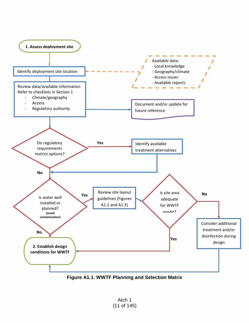
Figure A1.1. WWTF Planning and Selection Matrix
1. Assess deployment site
Identify deployment site location
Review data/available information Refer to checklists in Section 1
- Climate/geography - Access - Regulatory authority
Do regulatory requirements
restrict options?
Identify available treatment alternatives
Document and/or update for future reference
Available data: - Local knowledge - Geography/climate - Access issues - Available reports
Is water well installed or planned?
(avoid contamination)
2. Establish design conditions for WWTF
No
No
Review site layout guidelines (Figures
A1.2 and A1.3)
Yes
Yes
No Is site area adequate for WWTF
onsite?
Consider additional treatment and/or disinfection during
design
Yes
Atch 1
(11 of 145)
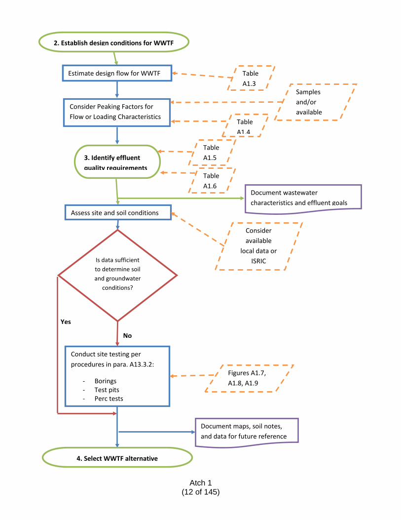
2. Establish design conditions for WWTF
Consider Peaking Factors for
Consider Peaking Factors for Flow or Loading Characteristics
Samples and/or available
Table A1.4
Table A1.3
3. Identify effluent quality requirements
Document wastewater characteristics and effluent goals
Table A1.5
Assess site and soil conditions
Consider available
local data or ISRIC
Conduct site testing per procedures in para. A13.3.2:
- Borings - Test pits - Perc tests
Is data sufficient to determine soil and groundwater
conditions?
No
Yes
Document maps, soil notes, and data for future reference
Figures A1.7, A1.8, A1.9
4. Select WWTF alternative
Table A1.6
Estimate design flow for WWTF
Atch 1
(12 of 145)
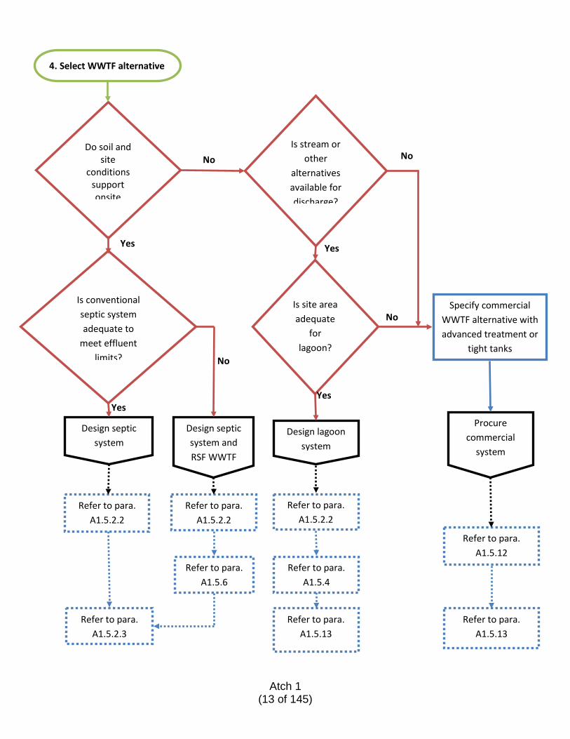
4. Select WWTF alternative
Do soil and site
conditions support onsite
Is conventional septic system adequate to
meet effluent limits?
Is site area adequate
for lagoon?
Is stream or other
alternatives available for discharge?
Specify commercial WWTF alternative with advanced treatment or
tight tanks
Refer to para. A1.5.12
Design septic system
Design septic system and RSF WWTF
Design lagoon system
Refer to para. A1.5.2.2
Refer to para. A1.5.2.3
Refer to para. A1.5.2.2
Refer to para. A1.5.6
Refer to para. A1.5.2.2
Refer to para. A1.5.4
Refer to para. A1.5.13
Refer to para. A1.5.13
No No
No
No
Yes
Yes Yes
Yes
Procure commercial
system
Atch 1
(13 of 145)
A1.2. PUBLIC HEALTH RISKS ASSOCIATED WITH UNTREATED WASTEWATER
A1.2.1. CONSTITUENTS OF DOMESTIC WASTEWATER
Domestic wastewater contains a combination of biological and chemical waste products. After use, this water must ultimately return to the environment and rejoin the hydrologic cycle by being discharged into a surface water body (such as a lake or stream) or into the groundwater supply. Left untreated, this wastewater can cause harm to the health and wellbeing of humans and ecosystems. Biological wastes can contain harmful organisms such as waterborne pathogens that can cause a myriad of illnesses including, but not limited to, cholera, typhoid, dysentery, and other infections. While some of the illnesses may pass in a few days to a week, they can also last much longer and without proper treatment can cause long-term damage or fatalities. Untreated sewage also contains high volumes of nutrients, which, when discharged to the environment can, among other impacts, fertilize algae populations and cause blooms to develop. These blooms can be toxic to humans and damage aquatic environments. There are a variety of ways humans can come into contact with untreated wastewater, including recreational aquatic activities on contaminated water bodies, bathing, washing clothes or utensils, and food preparation or ingesting plants exposed to contaminated water sources. Contamination can occur by direct consumption or by more subtle contact with the skin, eyes, or ears.
A1.2.2. INTERNATIONAL GUIDANCE FOR SANITATION AND HEALTH
As identified by the WHO, countries are at varying levels of sanitation awareness and sensitivity with respect to wastewater treatment and the protection of both groundwater and surface waters. These differences are based largely on cultural, educational, and economic development factors. In industrial countries, degradation of surface and groundwater sources has previously been a consequence of economic development while environmental impacts had been a lesser priority. In undeveloped countries, cultural practices and a lack of education about the relationship between water quality and disease is unfortunately still a major world health issue. The international community has acknowledged the severity of the problems caused by deteriorating water quality and agreed to take action to protect the quality of freshwater resources.
A1.3. SITE EVALUATION WWTF placement depends on other site features and planned improvements at the deployment site, including:
• Location/type of water supply source • Location of surface water features and/or wetlands • Presence of significant ledge • Site topography • Available area in the deployment site
Atch 1
(14 of 145)
A preliminary site evaluation for these features is the first step in selecting a general area for the WWTFs, with the primary goals being health and safety, protection of the onsite water supply well (if present), and minimizing nuisance issues for personnel. Figure A1.2 shows a sample arrangement at a deployment site for a conventional septic system sized to treat up to 3,000 gallons per day (gpd) (11,360 liters per day [Lpd]) of wastewater. This arrangement assumes that the soil characteristics will support a leaching field and provides the smallest footprint while considering the following:
• Adequate offset between the water supply well and other features • Gravity sewer piping to carry flows away from sources • Location of septic tank away from housing and kitchen facilities to reduce odors • Location of leaching field away from vehicle traffic • Adequate offset between surface water and wastewater facilities (see A1.3.4.3)
Figure A1.3 shows a sample arrangement for the same design flow at a similar deployment site where the soil conditions are not favorable for an onsite leaching field. In this case, a lagoon system is the selected treatment arrangement. The lagoon system should include two cells and effluent screening prior to the surface water discharge. For both cases there are recommended Do’s and Don’ts for site management and use that protects the long-term viability of the water and wastewater facilities at the site. The following recommendations apply:
1. Maintain water supply offsets to potential contaminant sources: • Locate sewer pipes, latrines, and tanks at least 300 feet (92 meters [m]) from
the public water supply well • Locate the leaching field at least 400 feet (122 m) from the well • Locate fuel storage at least 400 feet (122 m) from the well
2. Protect the sewer system and leaching area from damage:
• Do not park or drive vehicles over treatment system areas • Establish vehicle access outside these areas • Do not dig or construct within 10 feet (3 m) of the leaching field • Consider only raised platforms over leach field for tent placement • Do not plant trees in the sewer or leach field areas • Consider grass or shallow ground cover over field to prevent erosion • Do not drive over shallow sewer piping • Bury sewer piping at least 3 feet (1 m) deep if crossing a travelled way
3. Considerations for lagoons:
• Maintain 100-foot (30.5 m) buffer between toe of berms to surface waters • Avoid constructing lagoons in potential floodplain zones • Locate downwind and away from lodging and kitchen areas
Atch 1
(15 of 145)
• Locate at least 400 feet (122 m) away from water supplies A thorough site evaluation is needed to confirm the selected location can work from a more detailed design perspective and is the key to providing a successful onsite sewage treatment system in the most suitable location. The key criteria include climate, topography, geology, soil characteristics, surface water and groundwater risk factors, and other site conditions. There are many references included in paragraph A1.4 that identify favorable criteria for siting facilities and the required soil, site, and seasonal conditions that affect the design, operation, and performance of certain systems. While some extreme conditions may be beyond predictability, the intent of this ETL is to provide a simple outline to determine key site conditions that will help the evaluator compare the feasibility of one alternative over another for specific site conditions.
Atch 1
(16 of 145)
Figure A1.2. Site Layout Conventional Septic System
Atch 1
(17 of 145)
Figure A1.3. Site Layout Lagoon System
Atch 1 (18 of 145)
A1.3.1. CLIMATE
Climate can affect the performance of certain wastewater treatment alternatives and extreme climate conditions will likely prohibit or reduce the available options for a specific site. Extreme cold and/or permafrost conditions challenge below-ground construction of wastewater management facilities, but sites with these conditions are limited. Elsewhere, seasonal variations in temperature and precipitation must be considered, but will not be prohibitive for most alternatives. Other extreme conditions such as high temperatures, continuous heavy precipitation, or desert conditions must also be considered during design, but are also likely not prohibitive. The climate of a deployment location will impact site conditions, including soil and groundwater and surface water characteristics.
A1.3.2. TOPOGRAPHY AND GEOLOGY
Site topography should be considered in siting sanitary and dining facility sources of wastewater with respect to the intended sites for treatment and disposal sites for the collected wastewater. Where possible, gravity flow will minimize the need for pumping equipment and simplify design and operations. Geology will directly impact the constructability of a wastewater treatment system and preferred location. Surface water features and water supply well locations will require protection from contamination and thus impose additional siting limitations.
A1.3.3. SOIL CHARACTERISTICS
Soil survey data for an existing deployment site may be available from onsite personnel. For a new deployment location, general soils data may be obtained through the International Soil Reference and Information Centre (ISRIC) World Soil Information at http://www.isric.org/content/requests-soil-maps-and-reports. ISRIC is an independent foundation responsible for collecting, archiving, and distributing data and research information. This information is useful as background and an indication of potential problems that may be encountered; however, onsite testing is necessary to determine the suitability of a specific site.
A1.3.3.1. Soil Composition
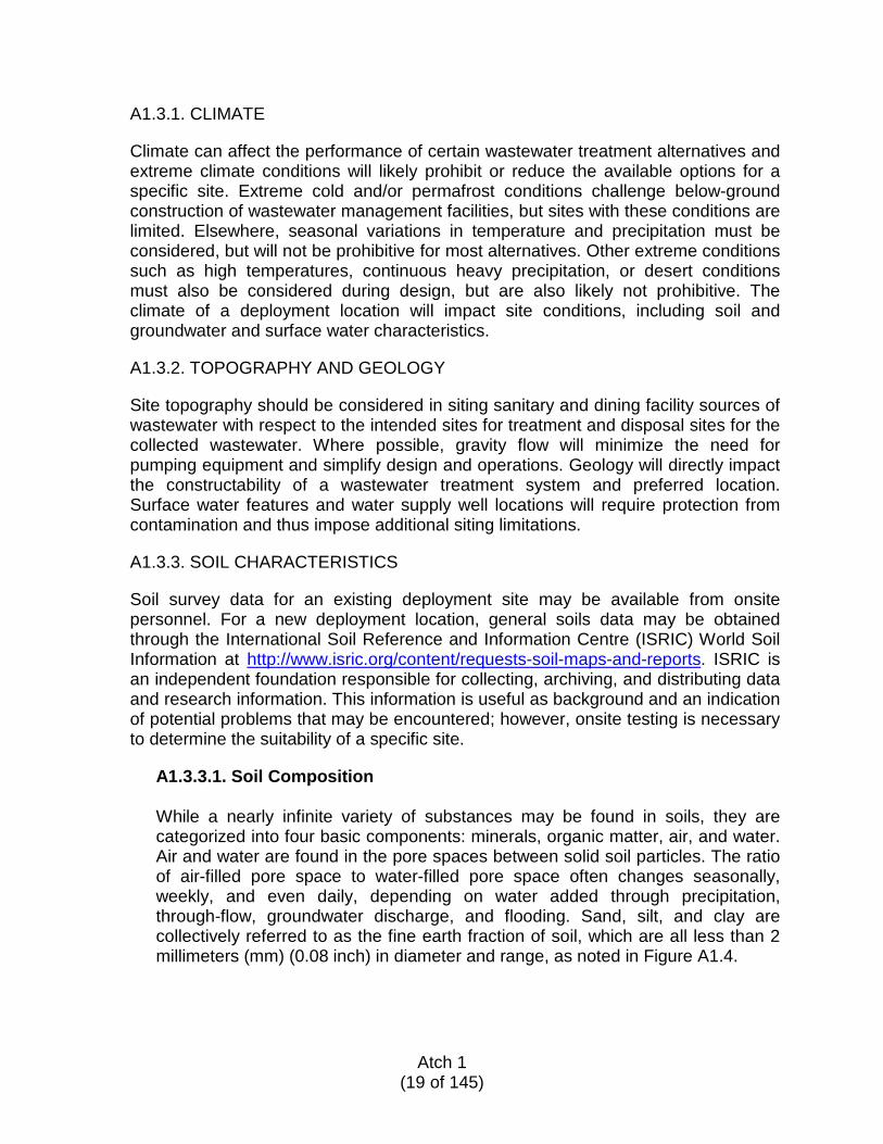
While a nearly infinite variety of substances may be found in soils, they are categorized into four basic components: minerals, organic matter, air, and water. Air and water are found in the pore spaces between solid soil particles. The ratio of air-filled pore space to water-filled pore space often changes seasonally, weekly, and even daily, depending on water added through precipitation, through-flow, groundwater discharge, and flooding. Sand, silt, and clay are collectively referred to as the fine earth fraction of soil, which are all less than 2 millimeters (mm) (0.08 inch) in diameter and range, as noted in Figure A1.4.
Atch 1
(19 of 145)
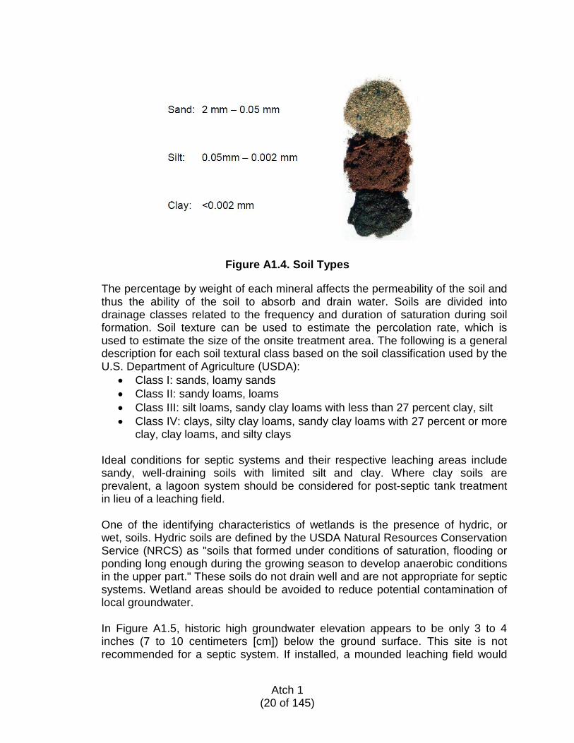
Figure A1.4. Soil Types
The percentage by weight of each mineral affects the permeability of the soil and thus the ability of the soil to absorb and drain water. Soils are divided into drainage classes related to the frequency and duration of saturation during soil formation. Soil texture can be used to estimate the percolation rate, which is used to estimate the size of the onsite treatment area. The following is a general description for each soil textural class based on the soil classification used by the U.S. Department of Agriculture (USDA):
• Class I: sands, loamy sands • Class II: sandy loams, loams • Class III: silt loams, sandy clay loams with less than 27 percent clay, silt • Class IV: clays, silty clay loams, sandy clay loams with 27 percent or more
clay, clay loams, and silty clays
Ideal conditions for septic systems and their respective leaching areas include sandy, well-draining soils with limited silt and clay. Where clay soils are prevalent, a lagoon system should be considered for post-septic tank treatment in lieu of a leaching field. One of the identifying characteristics of wetlands is the presence of hydric, or wet, soils. Hydric soils are defined by the USDA Natural Resources Conservation Service (NRCS) as "soils that formed under conditions of saturation, flooding or ponding long enough during the growing season to develop anaerobic conditions in the upper part." These soils do not drain well and are not appropriate for septic systems. Wetland areas should be avoided to reduce potential contamination of local groundwater. In Figure A1.5, historic high groundwater elevation appears to be only 3 to 4 inches (7 to 10 centimeters [cm]) below the ground surface. This site is not recommended for a septic system. If installed, a mounded leaching field would
Atch 1
(20 of 145)
be necessary to accomplish a 2- to 4-foot (0.6 to 1.2 m) offset to the high groundwater level shown.
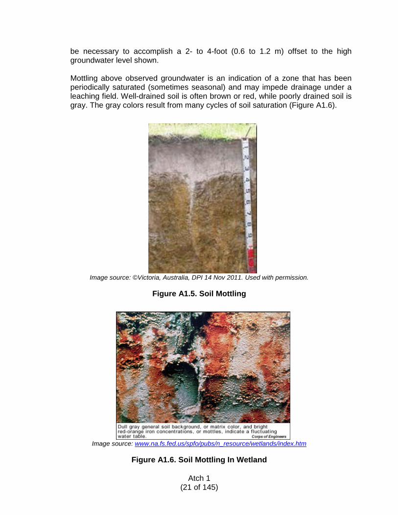
Mottling above observed groundwater is an indication of a zone that has been periodically saturated (sometimes seasonal) and may impede drainage under a leaching field. Well-drained soil is often brown or red, while poorly drained soil is gray. The gray colors result from many cycles of soil saturation (Figure A1.6).
Image source: ©Victoria, Australia, DPI 14 Nov 2011. Used with permission.
Figure A1.5. Soil Mottling
Image source: www.na.fs.fed.us/spfo/pubs/n_resource/wetlands/index.htm
Figure A1.6. Soil Mottling In Wetland
Atch 1 (21 of 145)
A1.3.3.2. Site Testing
Several borings (three per acre, eight per hectare) are recommended in the area proposed for a wastewater effluent leaching field or lagoon. Soil borings are necessary to determine the soil texture and depth to the groundwater table or ledge. If the deployment location is served by an onsite water supply well, the septic system should be installed down-gradient. Compare apparent groundwater elevations in each boring to estimate groundwater flow direction through the area. Refer to Figure A1.7 for a soil testing plan example. This plan shows the general locations of the recommended tests, to be performed in the following order:
1. Conduct boring study in the proposed wastewater system area to:
a. Assess general soil conditions b. Locate ledge or boulders that may hinder construction c. Locate water table, if encountered d. Identify other problem conditions
2. Identify the most appropriate location for the leaching area, considering:
a. Findings from boring study b. Slope of site
3. Dig observation pit(s) (as appropriate) based on the system size. These pits provide access for a more detailed analysis of the soil conditions to determine the following:
a. Presence of groundwater in the area and/or mottling point, if observed b. Presence of rocks or boulders in the immediate area c. Presence of clay or other hindering soil features d. Consistency of the materials in the area e. Approximate bottom of leaching field required to maintain adequate
distance to the groundwater
4. Dig percolation (perc) test holes and conduct tests in the intended leaching field area (following the procedure outlined below) to:
a. Measure percolation rate(s) throughout the area b. Establish percolation rate to use for design conditions c. Verify the location and bottom elevation of the leaching field
5. Dig the test pit to monitor groundwater during the percolation test.
Atch 1
(22 of 145)
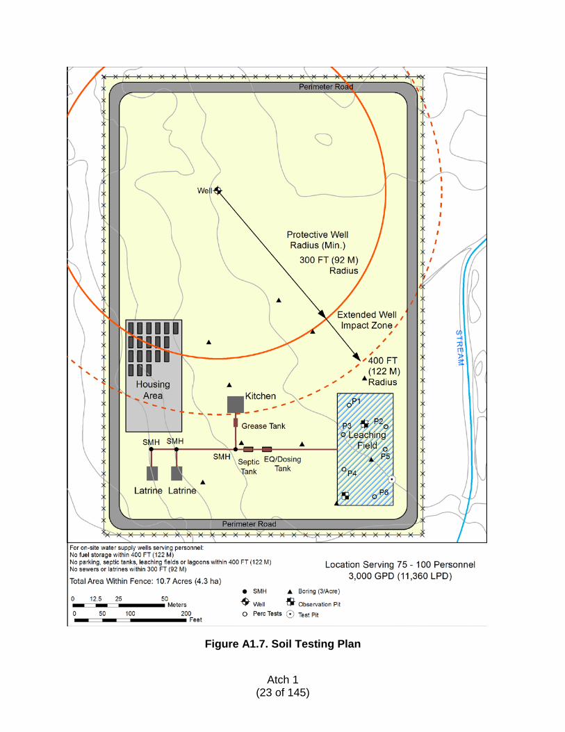
Figure A1.7. Soil Testing Plan
Atch 1
(23 of 145)
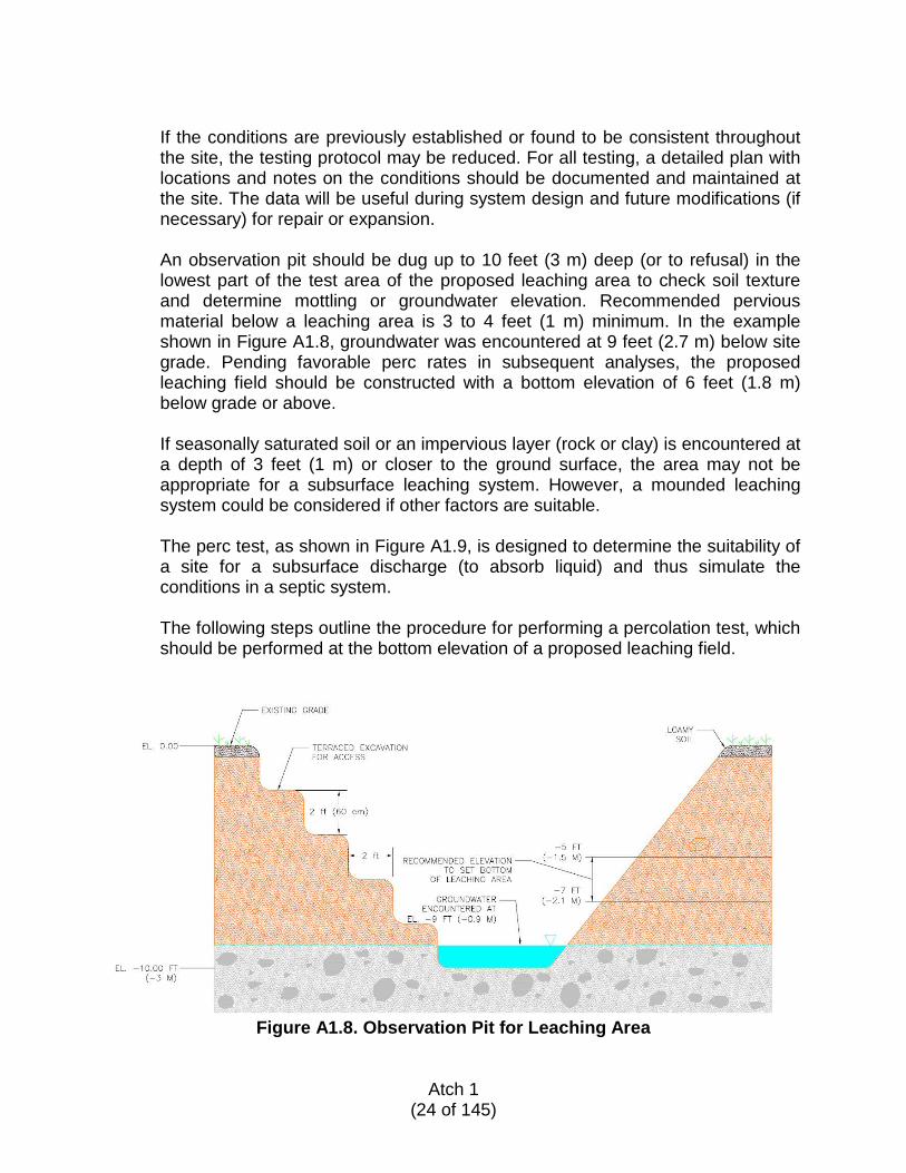
If the conditions are previously established or found to be consistent throughout the site, the testing protocol may be reduced. For all testing, a detailed plan with locations and notes on the conditions should be documented and maintained at the site. The data will be useful during system design and future modifications (if necessary) for repair or expansion. An observation pit should be dug up to 10 feet (3 m) deep (or to refusal) in the lowest part of the test area of the proposed leaching area to check soil texture and determine mottling or groundwater elevation. Recommended pervious material below a leaching area is 3 to 4 feet (1 m) minimum. In the example shown in Figure A1.8, groundwater was encountered at 9 feet (2.7 m) below site grade. Pending favorable perc rates in subsequent analyses, the proposed leaching field should be constructed with a bottom elevation of 6 feet (1.8 m) below grade or above.
If seasonally saturated soil or an impervious layer (rock or clay) is encountered at a depth of 3 feet (1 m) or closer to the ground surface, the area may not be appropriate for a subsurface leaching system. However, a mounded leaching system could be considered if other factors are suitable. The perc test, as shown in Figure A1.9, is designed to determine the suitability of a site for a subsurface discharge (to absorb liquid) and thus simulate the conditions in a septic system. The following steps outline the procedure for performing a percolation test, which should be performed at the bottom elevation of a proposed leaching field.
Figure A1.8. Observation Pit for Leaching Area
Atch 1
(24 of 145)
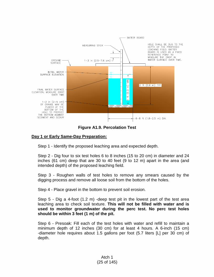
Figure A1.9. Percolation Test
Day 1 or Early Same-Day Preparation:
Step 1 - Identify the proposed leaching area and expected depth. Step 2 - Dig four to six test holes 6 to 8 inches (15 to 20 cm) in diameter and 24 inches (61 cm) deep that are 30 to 40 feet (9 to 12 m) apart in the area (and intended depth) of the proposed leaching field. Step 3 - Roughen walls of test holes to remove any smears caused by the digging process and remove all loose soil from the bottom of the holes. Step 4 - Place gravel in the bottom to prevent soil erosion. Step 5 - Dig a 4-foot (1.2 m) -deep test pit in the lowest part of the test area leaching area to check soil texture. This will not be filled with water and is used to monitor groundwater during the perc test. No perc test holes should be within 3 feet (1 m) of the pit. Step 6 - Presoak: Fill each of the test holes with water and refill to maintain a minimum depth of 12 inches (30 cm) for at least 4 hours. A 6-inch (15 cm) -diameter hole requires about 1.5 gallons per foot (5.7 liters [L] per 30 cm) of depth.
Atch 1
(25 of 145)
Step 7 - Prepare a measurement stake with nails or other markers located at specific intervals that can be easily observed. Refer to Figure A1.9.
Day 2 - Testing:
Step 1 - Prior to testing, clear bottoms of test holes of any loose soils or debris. Step 2 - If no water remains in the hole after the overnight soak period, add 6 inches (15 cm) of water above the gravel. Step 3 - Fill the test holes to a specific marker elevation (typically 12 to 18 inches (30 to 46 cm) above the bottom of the test hole and note the exact time. Step 4 - Measure the drop in water elevation after a set time period or the time required to drop to the next marker. Step 5 - After each measurement, re-fill the hole to a minimum depth of 6 inches (15 cm) above the bottom gravel. Step 6 - Calculate the percolation rate in minutes per inch (25 mm) of elevation drop. Step 7 - Continue taking measurements until three consecutive percolation rates vary by no more than 10 percent. Step 8 - Refer to Table A1.1 for the loading rates relative to percolation and soil textural class to determine the effluent loading rate on the leaching area.
Atch 1
(26 of 145)
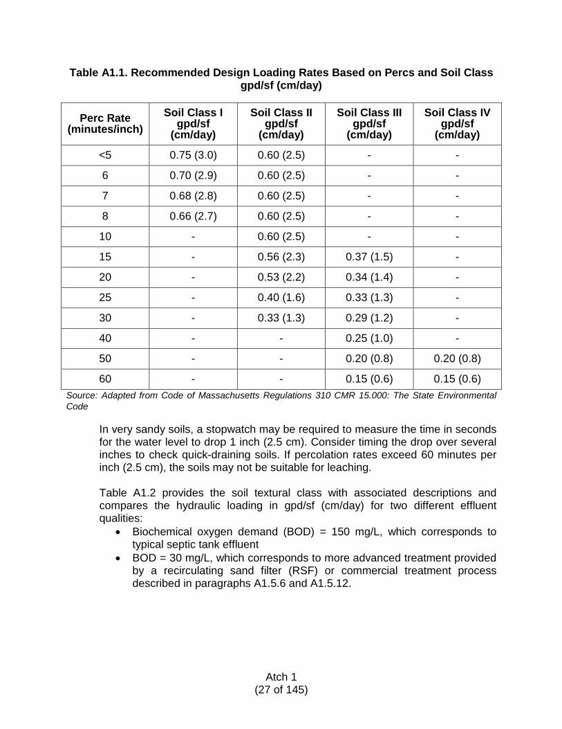
Table A1.1. Recommended Design Loading Rates Based on Percs and Soil Class gpd/sf (cm/day)
Perc Rate (minutes/inch)
Soil Class I gpd/sf
(cm/day)
Soil Class II gpd/sf
(cm/day)
Soil Class III gpd/sf
(cm/day)
Soil Class IV gpd/sf
(cm/day)
<5 0.75 (3.0) 0.60 (2.5) - -
6 0.70 (2.9) 0.60 (2.5) - -
7 0.68 (2.8) 0.60 (2.5) - -
8 0.66 (2.7) 0.60 (2.5) - -
10 - 0.60 (2.5) - -
15 - 0.56 (2.3) 0.37 (1.5) -
20 - 0.53 (2.2) 0.34 (1.4) -
25 - 0.40 (1.6) 0.33 (1.3) -
30 - 0.33 (1.3) 0.29 (1.2) -
40 - - 0.25 (1.0) -
50 - - 0.20 (0.8) 0.20 (0.8)
60 - - 0.15 (0.6) 0.15 (0.6) Source: Adapted from Code of Massachusetts Regulations 310 CMR 15.000: The State Environmental Code
In very sandy soils, a stopwatch may be required to measure the time in seconds for the water level to drop 1 inch (2.5 cm). Consider timing the drop over several inches to check quick-draining soils. If percolation rates exceed 60 minutes per inch (2.5 cm), the soils may not be suitable for leaching. Table A1.2 provides the soil textural class with associated descriptions and compares the hydraulic loading in gpd/sf (cm/day) for two different effluent qualities:
• Biochemical oxygen demand (BOD) = 150 mg/L, which corresponds to typical septic tank effluent
• BOD = 30 mg/L, which corresponds to more advanced treatment provided by a recirculating sand filter (RSF) or commercial treatment process described in paragraphs A1.5.6 and A1.5.12.
Atch 1
(27 of 145)
Table A1.2. Hydraulic/Organic Loading Rates for Infiltration Surfaces
Soil Textural
Class Texture
Description
Hydraulic loading, gpd/sf (cm/day)
Organic loading lb BOD/1000 ft2/day
(kg BOD/1000 m2/day)
BOD = 150 BOD = 30 BOD = 150 BOD = 30
I Coarse sand, sand, loamy coarse sand, loamy sand
0.8 (3.3)
1.6 (6.5)
1.00 (23.7)
0.40 (9.5)
I Fine sand, very fine sand, loamy fine sand, loamy very fine sand
0.4 (1.6)
1.0 (4.1)
0.50 (11.8)
0.25 (5.9)
II Coarse sandy loam, sandy loam
0.2–0.6 (0.8–2.4)
0.5–1.0 (2.0–4.1)
0.50 (11.8)
0.20 (4.7)
Il Fine sandy loam, very fine sandy loam
0.2–0.4 (0.8–1.6)
0.6–0.8 (2.4–3.3)
0.50 (11.8)
0.20 (4.7)
IIl Silty loam, silty clay loam
0.2–0.4 (0.8–1.6)
0.5–0.8 (2.0–3.3)
0.75 (17.8)
0.20 (4.7)
lV Sandy clay, clay
0.2 (0.8)
0.3 (1.2)
0.25 (5.9)
0.08 (1.9)
Source: Adapted from EPA Onsite Wastewater Treatment Systems Manual
As noted in Table A1.2, a higher loading rate is possible when the effluent being applied is of significantly improved quality. The higher loading rate allows a smaller leaching area for the same site conditions. This summary was adapted from the EPA-625/R-00/008, Onsite Wastewater Treatment Systems Manual, Table 4-3. The EPA Onsite Wastewater Treatment Systems Manual includes additional information on organic loading and should be consulted for detailed design information if the BOD value of the effluent is being considered.
For hydraulic loadings, control can be achieved by changing the geometry or size of the infiltrative surface or the dosing volume, frequency, and pattern. For organic or constituent loadings, control is achieved either by pretreating the wastewater before it is applied to the infiltrative surface or by increasing the size of the infiltration surface.
Atch 1
(28 of 145)
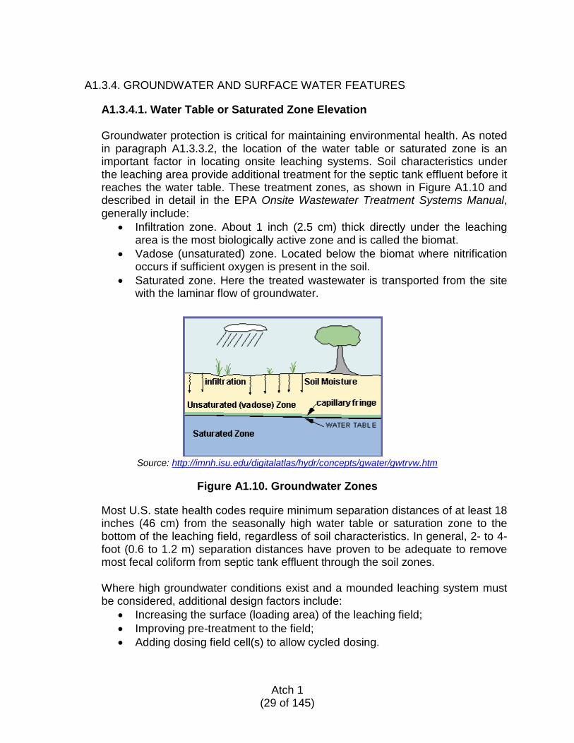
A1.3.4. GROUNDWATER AND SURFACE WATER FEATURES
A1.3.4.1. Water Table or Saturated Zone Elevation
Groundwater protection is critical for maintaining environmental health. As noted in paragraph A1.3.3.2, the location of the water table or saturated zone is an important factor in locating onsite leaching systems. Soil characteristics under the leaching area provide additional treatment for the septic tank effluent before it reaches the water table. These treatment zones, as shown in Figure A1.10 and described in detail in the EPA Onsite Wastewater Treatment Systems Manual, generally include:
• Infiltration zone. About 1 inch (2.5 cm) thick directly under the leaching area is the most biologically active zone and is called the biomat.
• Vadose (unsaturated) zone. Located below the biomat where nitrification occurs if sufficient oxygen is present in the soil.
• Saturated zone. Here the treated wastewater is transported from the site with the laminar flow of groundwater.
Source: http://imnh.isu.edu/digitalatlas/hydr/concepts/gwater/gwtrvw.htm
Figure A1.10. Groundwater Zones
Most U.S. state health codes require minimum separation distances of at least 18 inches (46 cm) from the seasonally high water table or saturation zone to the bottom of the leaching field, regardless of soil characteristics. In general, 2- to 4-foot (0.6 to 1.2 m) separation distances have proven to be adequate to remove most fecal coliform from septic tank effluent through the soil zones.
Where high groundwater conditions exist and a mounded leaching system must be considered, additional design factors include:
• Increasing the surface (loading area) of the leaching field; • Improving pre-treatment to the field; • Adding dosing field cell(s) to allow cycled dosing.
Atch 1
(29 of 145)
A1.3.4.2. Hydraulic Loading Limitations
The soil texture classification (sand, silt, and clay proportions) determined from the site excavation, and the percolation rate measured in the field, are used to define the conditions for long-term hydraulic loading. Where unsuitable silt and clay conditions exist, the limited hydraulic loading may eliminate onsite treatment from consideration. Where leaching systems cannot be constructed, a lagoon system should be considered as an alternative if adequate land is available onsite.
A1.3.4.3. Groundwater and Surface Water Protection
To minimize the potential impact from onsite treatment systems on nearby groundwater drinking water wells, wetlands, and surface water bodies such as ponds and streams, the following restrictions are recommended:
• 400-foot (122 m) minimum setback from drinking water supply source • 100-foot (30.5 m) minimum setback from leaching field or lagoon to
tributary stream • 50-foot (15 m) minimum setback from septic tank to surface water • 100-foot (30.5 m) minimum setback from leaching field to surface water
(not used for drinking water)
A1.3.5. FLOODPLAINS
Construction on floodplains is not recommended due to the potential for damage to the onsite systems and related risk of pollutant contamination. Where possible, a mounded leaching field and/or surface-located pre-treatment system could be considered beyond the floodplain area. All tanks and piping should be water-tight and tested to avoid contaminating the groundwater.
A1.4. DESIGN CONSIDERATIONS FOR TREATMENT SYSTEM SELECTION
A1.4.1. WASTEWATER CHARACTERISTICS; FLOW, COMPOSITION
Sanitary flows vary based on the source, water consumption, and site-specific conditions. As shown in Table A1.3, wastewater projections for deployed locations are significantly lower than typical U.S. locations where water supply is readily available, not typically restricted, and of consistently good quality. As identified in AFPAM 10-219V5, Bare Base Conceptual Planning Guide, an estimated 19.7 gallons per capita per day (gpcd) (74.6 liters per capita per day [Lpcd]) of wastewater is generated from an average water supply of 42.7 gpcd (162 Lpcd) of potable water using mobile water system assets. The water use difference may also affect the relative wastewater characteristics with respect to pollutant loading and design adjustments may be necessary. Where non-mobile water assets are available, typical water consumption is 60 gpcd (227 Lpcd), which generates an estimated 42.7 gpcd (162 Lpcd) of wastewater flow. In comparison, U.S. water
Atch 1
(30 of 145)
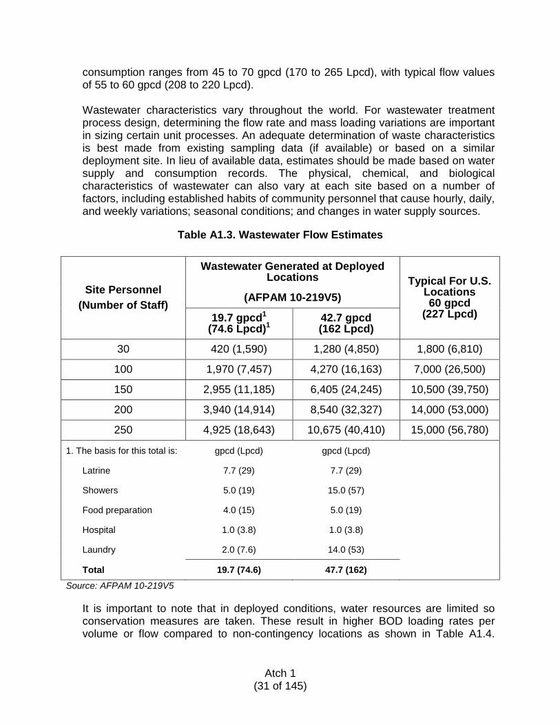
consumption ranges from 45 to 70 gpcd (170 to 265 Lpcd), with typical flow values of 55 to 60 gpcd (208 to 220 Lpcd). Wastewater characteristics vary throughout the world. For wastewater treatment process design, determining the flow rate and mass loading variations are important in sizing certain unit processes. An adequate determination of waste characteristics is best made from existing sampling data (if available) or based on a similar deployment site. In lieu of available data, estimates should be made based on water supply and consumption records. The physical, chemical, and biological characteristics of wastewater can also vary at each site based on a number of factors, including established habits of community personnel that cause hourly, daily, and weekly variations; seasonal conditions; and changes in water supply sources.
Table A1.3. Wastewater Flow Estimates
Site Personnel (Number of Staff)
Wastewater Generated at Deployed Locations Typical For U.S.
Locations 60 gpcd
(227 Lpcd) (AFPAM 10-219V5)
19.7 gpcd1 (74.6 Lpcd)1
42.7 gpcd (162 Lpcd)
30 420 (1,590) 1,280 (4,850) 1,800 (6,810)
100 1,970 (7,457) 4,270 (16,163) 7,000 (26,500)
150 2,955 (11,185) 6,405 (24,245) 10,500 (39,750)
200 3,940 (14,914) 8,540 (32,327) 14,000 (53,000)
250 4,925 (18,643) 10,675 (40,410) 15,000 (56,780)
1. The basis for this total is: gpcd (Lpcd) gpcd (Lpcd)
Latrine 7.7 (29) 7.7 (29)
Showers 5.0 (19) 15.0 (57)
Food preparation 4.0 (15) 5.0 (19)
Hospital 1.0 (3.8) 1.0 (3.8)
Laundry 2.0 (7.6) 14.0 (53)
Total 19.7 (74.6) 47.7 (162)
Source: AFPAM 10-219V5
It is important to note that in deployed conditions, water resources are limited so conservation measures are taken. These result in higher BOD loading rates per volume or flow compared to non-contingency locations as shown in Table A1.4.
Atch 1
(31 of 145)
Designing for the appropriate BOD loading rate and ambient temperature is key to achieving desired levels of treatment. Another important concern that needs to be addressed is chemical wastes in wastewater. In general, the treatment alternatives listed in this ETL are designed for biological wastes (e.g., human waste, handwash-water). Disposing of chemicals in the wastewater treatment process will inhibit treatment and damage the process. The most notable chemicals are those used in portable toilets or chemical toilets. If these types of toilets are widely used, it is recommended that commercial package plants designed to handle that type of waste should be used. Unfortunately, there are no typical values for wastewater because it varies so much and depends on many factors. Table A1.4 is a summary of cited values based on a review of published data. From this starting point, estimated values are presented to reflect expected concentrations for two deployment site conditions: one where the water supply is limited to mobile sources; the other where the water supply is permanent, such as an onsite well or a connection to a nearby water supply.
Atch 1
(32 of 145)
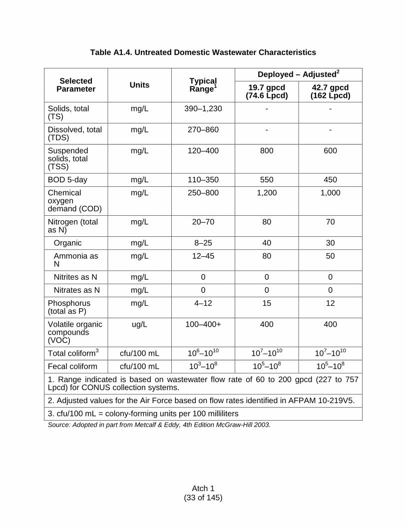
Table A1.4. Untreated Domestic Wastewater Characteristics
Selected Parameter Units Typical
Range1
Deployed – Adjusted2 19.7 gpcd
(74.6 Lpcd) 42.7 gpcd (162 Lpcd)
Solids, total (TS)
mg/L 390–1,230 - -
Dissolved, total (TDS)
mg/L 270–860 - -
Suspended solids, total (TSS)
mg/L 120–400 800 600
BOD 5-day mg/L 110–350 550 450 Chemical oxygen demand (COD)
mg/L 250–800 1,200 1,000
Nitrogen (total as N)
mg/L 20–70 80 70
Organic mg/L 8–25 40 30 Ammonia as N
mg/L 12–45 80 50
Nitrites as N mg/L 0 0 0 Nitrates as N mg/L 0 0 0
Phosphorus (total as P)
mg/L 4–12 15 12
Volatile organic compounds (VOC)
ug/L 100–400+ 400 400
Total coliform3 cfu/100 mL 106–1010 107–1010 107–1010 Fecal coliform cfu/100 mL 103–108 105–108 105–108 1. Range indicated is based on wastewater flow rate of 60 to 200 gpcd (227 to 757 Lpcd) for CONUS collection systems. 2. Adjusted values for the Air Force based on flow rates identified in AFPAM 10-219V5. 3. cfu/100 mL = colony-forming units per 100 milliliters Source: Adopted in part from Metcalf & Eddy, 4th Edition McGraw-Hill 2003.
Atch 1
(33 of 145)
A1.4.2. WATER QUALITY STANDARDS APPLICABLE TO STREAM OR SURFACE WATER DISCHARGE
Regulatory requirements mandated by international agreement, DOD policy, or combatant command/operational chain of command must be considered in selecting the wastewater treatment design that best meets the needs of the site. For example, the OEBGD regulates discharges to surface waters with limitations for BOD and TSS of 30 mg/L each for 30-day average flows and 45 mg/L for seven-day average flows. These limits are consistent with U.S. WWTFs currently in operation with surface water discharges. However, in many regions of the U.S., individual states have imposed more stringent limits for nitrogen and phosphorus in an effort to limit nutrient loading on local streams and harbors. The same concerns may exist at a deployment location and should be considered if a surface water discharge is pursued at a deployment site. Surface water and/or stream discharges are not typically pursued for onsite systems; instead, groundwater recharge is encouraged through leaching field effluent disposal. In situations where a leaching field is not possible or feasible, pretreatment before surface water discharge would require one of the advanced treatment systems described in paragraph A1.5, with an additional requirement for disinfection. Another alternative to consider would be a non-discharging lagoon system, depending on the size of the deployment site and staff generating the wastewater.
A1.4.3. WATER QUALITY STANDARDS APPLICABLE TO SUBSURFACE/GROUNDWATER DISCHARGE
The focus of this ETL is for WWTFs intended to serve contingency locations staffed with 30 to 250 personnel. For this size facility, the estimated flow ranges from less than 1,000 gpd (3,790 Lpd) up to 10,000 gpd (37,850 Lpd) for a site with non-mobile water supplies and much lower design flows for sites served with mobile water supplies. In this range, onsite systems with groundwater discharge are often the most simple, expedient, long-term management plan. Numerous studies have shown that conventional septic treatment and leaching systems achieve high removal rates for most pollutants of concern; biochemical oxygen demand, suspended solids, fecal coliform, and ammonia nitrogen are effectively removed by soil filtration through the biomat. Reductions in viruses and toxic organics are also effectively treated in the aerobic subsoil and high temperatures. However, nitrate generated from ammonia conversion is highly soluble and passes through to the groundwater. Chlorides also pass through to the groundwater as a result of their solubility. Table A1.5 presents the recommended effluent water quality under various site conditions, including protective zones for water supply wells or other nitrogen-sensitive areas. In general, the estimated water quality at the point where the leaching field effluent meets the groundwater typically includes 50 mg/L BOD, 50
Atch 1
(34 of 145)
mg/L TSS, and 45 mg/L total nitrogen. As shown in Table A1.5, the conventional septic system meets these limits for lower flows. Where additional nitrogen reduction requires denitrification to meet sensitive groundwater conditions, advanced treatment such as a recirculating sand filter (RSF) or a commercially available alternative treatment system described in paragraphs A1.5.7 and A1.5.12 should be considered. These systems can reliably produce an effluent quality of 30 mg/L BOD and TSS, 25 mg/L total nitrogen to the leaching field, and are typically required for facilities treating higher wastewater flows, as indicated.
A1.4.4. CHARACTERISTICS OF RECEIVING SITE
Receiving site characteristics can be initially assessed by a physical survey or report from local representatives. The climate, size of the site, physical features and restrictions, and security should all be considered when reviewing alternatives. In addition, the personnel population, both initially and long-term for the deployment, may be a factor. Site requirements with respect to expected term for the deployment location, funding limitations for construction, and/or long-term O&M costs will be important factors in selecting an alternative. All of these factors are critical to selecting a successful wastewater plan that addresses the needs of the deployment location in the most efficient and cost-effective manner. The WWTF Planning and Selection Matrix in Figure A1.1 identifies and qualifies key factors to consider that will facilitate a decision on the most appropriate system for a specific site. Treatment alternatives to consider are described in paragraph A1.5.
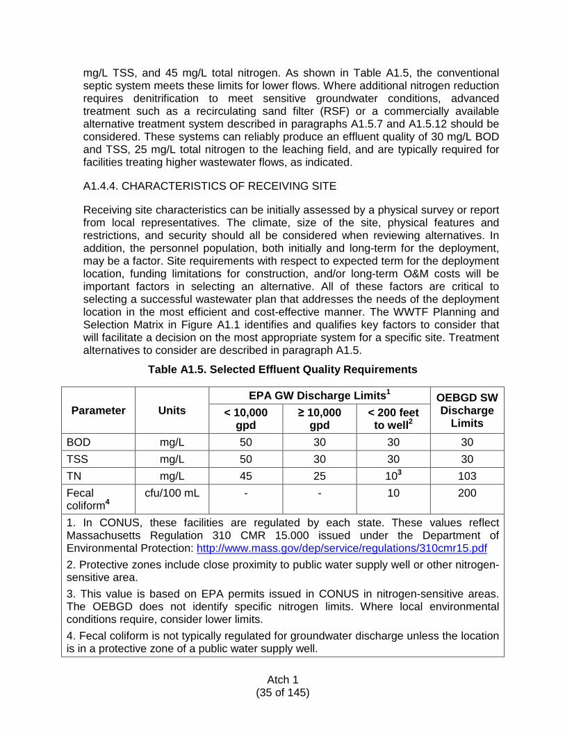
Table A1.5. Selected Effluent Quality Requirements
Parameter Units EPA GW Discharge Limits1 OEBGD SW
Discharge Limits
< 10,000 gpd
≥ 10,000 gpd
< 200 feet to well2
BOD mg/L 50 30 30 30 TSS mg/L 50 30 30 30 TN mg/L 45 25 103 103 Fecal coliform4
cfu/100 mL - - 10 200
1. In CONUS, these facilities are regulated by each state. These values reflect Massachusetts Regulation 310 CMR 15.000 issued under the Department of Environmental Protection: http://www.mass.gov/dep/service/regulations/310cmr15.pdf 2. Protective zones include close proximity to public water supply well or other nitrogen-sensitive area. 3. This value is based on EPA permits issued in CONUS in nitrogen-sensitive areas. The OEBGD does not identify specific nitrogen limits. Where local environmental conditions require, consider lower limits. 4. Fecal coliform is not typically regulated for groundwater discharge unless the location is in a protective zone of a public water supply well.
Atch 1
(35 of 145)
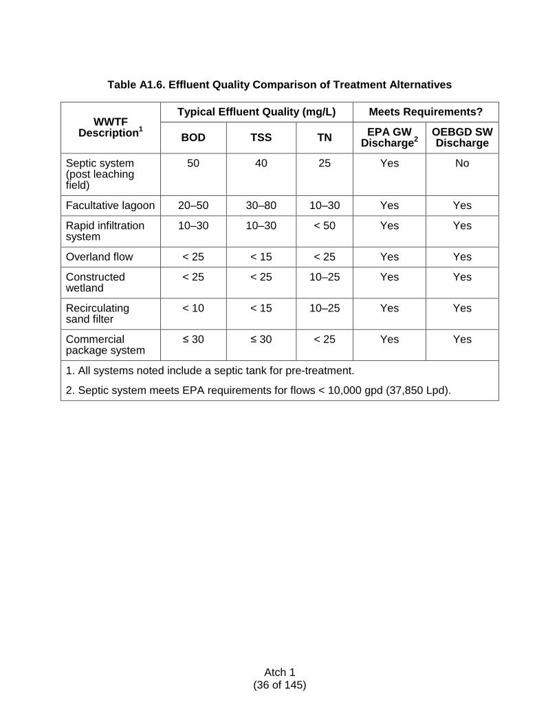
Table A1.6. Effluent Quality Comparison of Treatment Alternatives
WWTF Description1
Typical Effluent Quality (mg/L) Meets Requirements?
BOD TSS TN EPA GW Discharge2
OEBGD SW Discharge
Septic system (post leaching field)
50 40 25 Yes No
Facultative lagoon 20–50 30–80 10–30 Yes Yes
Rapid infiltration system
10–30 10–30 < 50 Yes Yes
Overland flow < 25 < 15 < 25 Yes Yes
Constructed wetland
< 25 < 25 10–25 Yes Yes
Recirculating sand filter
< 10 < 15 10–25 Yes Yes
Commercial package system
≤ 30 ≤ 30 < 25 Yes Yes
1. All systems noted include a septic tank for pre-treatment.
2. Septic system meets EPA requirements for flows < 10,000 gpd (37,850 Lpd).
Atch 1
(36 of 145)
A1.5. TREATMENT SYSTEM ALTERNATIVES The described alternatives may or may not be practical or otherwise allowed at a particular site because of legal, operational, or practical (e.g., natural terrain) factors.
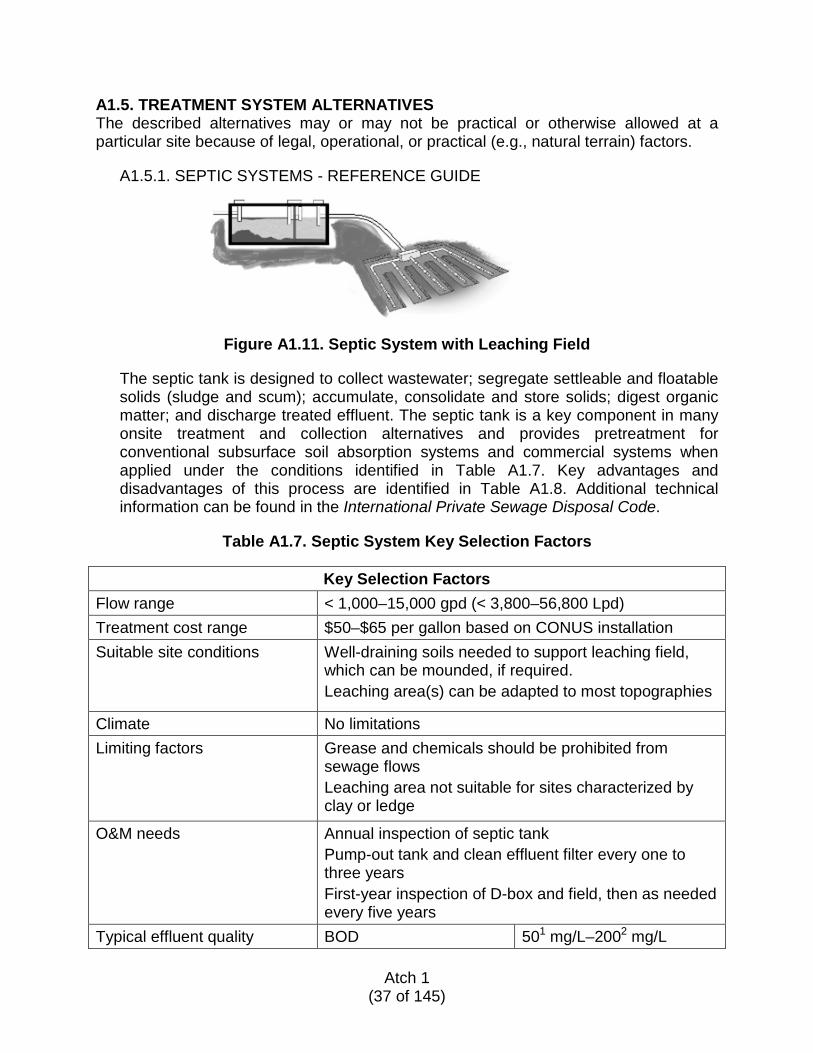
A1.5.1. SEPTIC SYSTEMS - REFERENCE GUIDE
Figure A1.11. Septic System with Leaching Field
The septic tank is designed to collect wastewater; segregate settleable and floatable solids (sludge and scum); accumulate, consolidate and store solids; digest organic matter; and discharge treated effluent. The septic tank is a key component in many onsite treatment and collection alternatives and provides pretreatment for conventional subsurface soil absorption systems and commercial systems when applied under the conditions identified in Table A1.7. Key advantages and disadvantages of this process are identified in Table A1.8. Additional technical information can be found in the International Private Sewage Disposal Code.
Table A1.7. Septic System Key Selection Factors
Key Selection Factors
Flow range < 1,000–15,000 gpd (< 3,800–56,800 Lpd) Treatment cost range $50–$65 per gallon based on CONUS installation Suitable site conditions Well-draining soils needed to support leaching field,
which can be mounded, if required. Leaching area(s) can be adapted to most topographies
Climate No limitations Limiting factors Grease and chemicals should be prohibited from
sewage flows Leaching area not suitable for sites characterized by clay or ledge
O&M needs Annual inspection of septic tank Pump-out tank and clean effluent filter every one to three years First-year inspection of D-box and field, then as needed every five years
Typical effluent quality BOD 501 mg/L–2002 mg/L
Atch 1 (37 of 145)
1. Leaching field effluent TSS 401 mg/L–1402 mg/L 2. Septic tank effluent TN 251 mg/L–502 mg/L Fecal coliform < 24,000/100 mL
Table A1.8. Septic System Advantages/Disadvantages
Advantages Disadvantages
Uses less energy than all other wastewater treatment methods.
Effluent quality is mediocre at best. Additional treatment provided through leaching field.
Simple construction and installation. Multiple tanks can be served by common leaching system.
Not well-suited for large populations
Simple to operate and maintain and generally requires minimal attention.
Poor septic tank and filter maintenance could cause leaching field failure
Suitable for most climates and seasonal variations
Mounded leaching required in areas of high groundwater
Functions as pretreatment for all other technologies Septic tank can serve as holding tank before subsequent drainfield or lagoon is installed
Effluent requires further processing before discharge to ground or surface waters
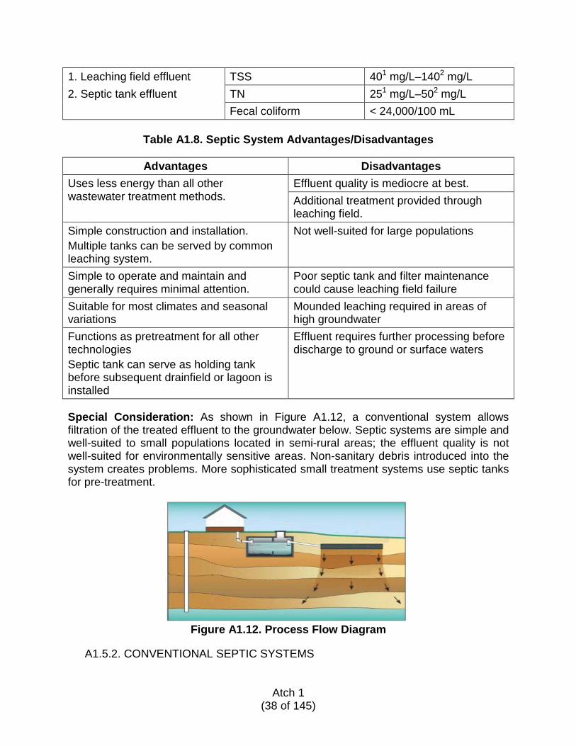
Special Consideration: As shown in Figure A1.12, a conventional system allows filtration of the treated effluent to the groundwater below. Septic systems are simple and well-suited to small populations located in semi-rural areas; the effluent quality is not well-suited for environmentally sensitive areas. Non-sanitary debris introduced into the system creates problems. More sophisticated small treatment systems use septic tanks for pre-treatment.
Figure A1.12. Process Flow Diagram
A1.5.2. CONVENTIONAL SEPTIC SYSTEMS
Atch 1
(38 of 145)
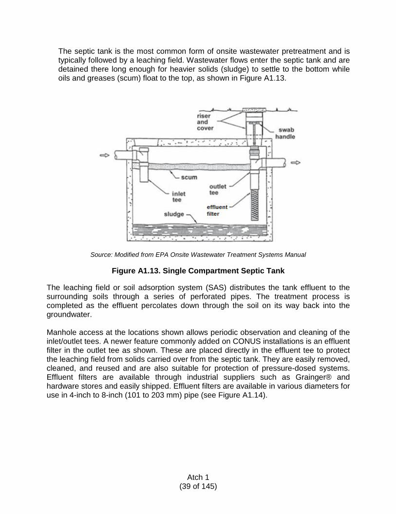
The septic tank is the most common form of onsite wastewater pretreatment and is typically followed by a leaching field. Wastewater flows enter the septic tank and are detained there long enough for heavier solids (sludge) to settle to the bottom while oils and greases (scum) float to the top, as shown in Figure A1.13.
Source: Modified from EPA Onsite Wastewater Treatment Systems Manual
Figure A1.13. Single Compartment Septic Tank The leaching field or soil adsorption system (SAS) distributes the tank effluent to the surrounding soils through a series of perforated pipes. The treatment process is completed as the effluent percolates down through the soil on its way back into the groundwater. Manhole access at the locations shown allows periodic observation and cleaning of the inlet/outlet tees. A newer feature commonly added on CONUS installations is an effluent filter in the outlet tee as shown. These are placed directly in the effluent tee to protect the leaching field from solids carried over from the septic tank. They are easily removed, cleaned, and reused and are also suitable for protection of pressure-dosed systems. Effluent filters are available through industrial suppliers such as Grainger® and hardware stores and easily shipped. Effluent filters are available in various diameters for use in 4-inch to 8-inch (101 to 203 mm) pipe (see Figure A1.14).
Atch 1
(39 of 145)
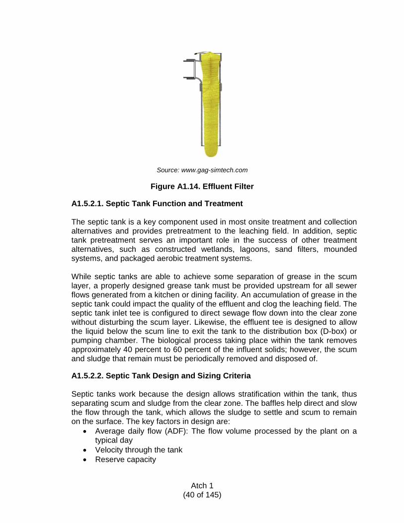
Source: www.gag-simtech.com
Figure A1.14. Effluent Filter
A1.5.2.1. Septic Tank Function and Treatment
The septic tank is a key component used in most onsite treatment and collection alternatives and provides pretreatment to the leaching field. In addition, septic tank pretreatment serves an important role in the success of other treatment alternatives, such as constructed wetlands, lagoons, sand filters, mounded systems, and packaged aerobic treatment systems. While septic tanks are able to achieve some separation of grease in the scum layer, a properly designed grease tank must be provided upstream for all sewer flows generated from a kitchen or dining facility. An accumulation of grease in the septic tank could impact the quality of the effluent and clog the leaching field. The septic tank inlet tee is configured to direct sewage flow down into the clear zone without disturbing the scum layer. Likewise, the effluent tee is designed to allow the liquid below the scum line to exit the tank to the distribution box (D-box) or pumping chamber. The biological process taking place within the tank removes approximately 40 percent to 60 percent of the influent solids; however, the scum and sludge that remain must be periodically removed and disposed of.
A1.5.2.2. Septic Tank Design and Sizing Criteria
Septic tanks work because the design allows stratification within the tank, thus separating scum and sludge from the clear zone. The baffles help direct and slow the flow through the tank, which allows the sludge to settle and scum to remain on the surface. The key factors in design are:
• Average daily flow (ADF): The flow volume processed by the plant on a typical day
• Velocity through the tank • Reserve capacity
Atch 1
(40 of 145)

• Solids storage capacity • Hydraulic retention time • Recommended length to width ratio is 3:1 • Clear zone volume is 1.5 to 2 times the daily design flow • Reserve sludge volume requires an additional 3-foot (0.9 m) reserve in
tank bottom • Minimum of 1-foot (0.3 m) surface is recommended for venting and scum
accumulation • Single-compartment septic tanks are adequate for single-unit applications
and lower design flows • For flows over 750 gpd (2,840 Lpd), a two-compartment tank is
recommended for improved reliability and performance
Septic Tank Design
The following is a step-by-step guide to designing a dual-chamber septic tank.
1. Determine the ADF for the facility. The ADF is based on the number of personnel and water use. Refer to Table A1.3 for expected flows. 2. Determine total storage volume required for each chamber. In a dual-chamber septic tank, the first chamber into which sewage flows should have a detention time of 48 hours. The second chamber should have a detention time of 24 hours. Detention time is the length of time required for one complete volume change.
V (gallons) = ADF gpd x detention time (days)
3. Convert storage volume from gallons to cubic feet.
V (ft3) = V (gallons) ÷ 7.48 gallons per cubic foot
4. Determine interior dimensions of both chambers. The total available volume of the tank (Vavail) should be equal to or greater than the volume calculated for the required detention times.
• The first chamber represents two-thirds of the volume • The second chamber represents one-third of the volume.
L1 = W L2 = 2 x L1 H = 6 feet to 16 feet (max) Vavail (ft3) = (L1 x W x H) + (L2 x W x H)
5. Establish maximum allowable sludge accumulation. The sludge should not accumulate to more than 3 feet (0.9 m) or 25 percent to 35 percent of the first chamber.
Atch 1
(41 of 145)
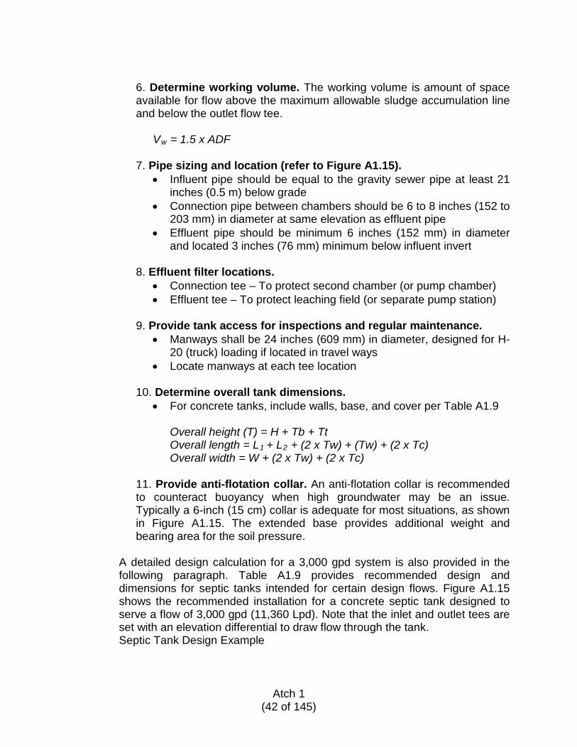
6. Determine working volume. The working volume is amount of space available for flow above the maximum allowable sludge accumulation line and below the outlet flow tee.
Vw = 1.5 x ADF
7. Pipe sizing and location (refer to Figure A1.15). • Influent pipe should be equal to the gravity sewer pipe at least 21
inches (0.5 m) below grade • Connection pipe between chambers should be 6 to 8 inches (152 to
203 mm) in diameter at same elevation as effluent pipe • Effluent pipe should be minimum 6 inches (152 mm) in diameter
and located 3 inches (76 mm) minimum below influent invert
8. Effluent filter locations. • Connection tee – To protect second chamber (or pump chamber) • Effluent tee – To protect leaching field (or separate pump station)
9. Provide tank access for inspections and regular maintenance.
• Manways shall be 24 inches (609 mm) in diameter, designed for H-20 (truck) loading if located in travel ways
• Locate manways at each tee location 10. Determine overall tank dimensions.
• For concrete tanks, include walls, base, and cover per Table A1.9
Overall height (T) = H + Tb + Tt Overall length = L1 + L2 + (2 x Tw) + (Tw) + (2 x Tc) Overall width = W + (2 x Tw) + (2 x Tc)
11. Provide anti-flotation collar. An anti-flotation collar is recommended to counteract buoyancy when high groundwater may be an issue. Typically a 6-inch (15 cm) collar is adequate for most situations, as shown in Figure A1.15. The extended base provides additional weight and bearing area for the soil pressure.
A detailed design calculation for a 3,000 gpd system is also provided in the following paragraph. Table A1.9 provides recommended design and dimensions for septic tanks intended for certain design flows. Figure A1.15 shows the recommended installation for a concrete septic tank designed to serve a flow of 3,000 gpd (11,360 Lpd). Note that the inlet and outlet tees are set with an elevation differential to draw flow through the tank. Septic Tank Design Example
Atch 1
(42 of 145)
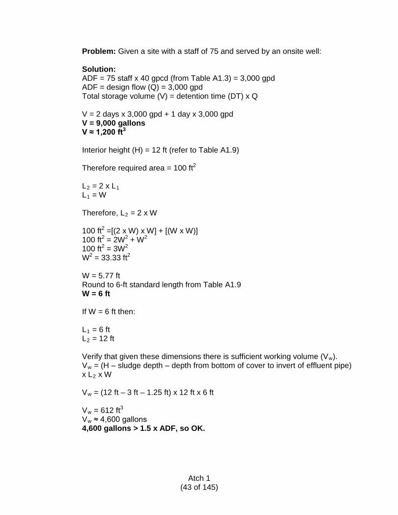
Problem: Given a site with a staff of 75 and served by an onsite well: Solution: ADF = 75 staff x 40 gpcd (from Table A1.3) = 3,000 gpd ADF = design flow (Q) = 3,000 gpd Total storage volume (V) = detention time (DT) x Q
V = 2 days x 3,000 gpd + 1 day x 3,000 gpd V = 9,000 gallons V ≈ 1,200 ft3
Interior height (H) = 12 ft (refer to Table A1.9) Therefore required area = 100 ft2 L2 = 2 x L1 L1 = W Therefore, L2 = 2 x W 100 ft2 =[(2 x W) x W] + [(W x W)] 100 ft2 = 2W2 + W2 100 ft2 = 3W2 W2 = 33.33 ft2
W = 5.77 ft Round to 6-ft standard length from Table A1.9 W = 6 ft If W = 6 ft then: L1 = 6 ft L2 = 12 ft Verify that given these dimensions there is sufficient working volume (Vw). Vw = (H – sludge depth – depth from bottom of cover to invert of effluent pipe) x L2 x W Vw = (12 ft – 3 ft – 1.25 ft) x 12 ft x 6 ft Vw = 612 ft3 Vw ≈ 4,600 gallons 4,600 gallons > 1.5 x ADF, so OK.
Atch 1
(43 of 145)

Summary of design: Tank dimensions: H = 12 ft L1 = 6 ft L2 = 12 ft W = 6 ft Septic tanks must be water-tight and are typically constructed of reinforced concrete as shown in Figure A1.15. Steel tanks require corrosive-resistant coatings and cathodic protection so they are not widely used. Fiberglass and polyethylene-molded tanks are also available but must be installed below ground with anti-buoyancy provisions. If concrete tanks cannot be manufactured locally and must be shipped, polyethylene tanks should be considered for ease and cost of delivery but availability may be limited in the larger tank sizes. If polyethylene tanks are desired, consider separating the wastewater flows into two separate treatment trains to reduce the tank sizing requirements.
Atch 1
(44 of 145)
Table A1.9. Septic Tank Sizing
Dual Chamber Septic Tank Design
Unit Symbol Flows
Wastewater flow (ADF)
gpd (Lpd)
Q 500 (1,900)
1,000 (3,785)
3,000 (11,360)
5,000 (18,930)
10,000 (37,860)
Tank
Total volume Gallons V 1,500 3,000 9,000 15,000 30,000
Working volume
Gallons Vw 750 1,500 4,500 7,500 15,000
Length chamber 1
Feet L1 3 4 6 7.5 10
Length chamber 2
Feet L2 6 8 12 15 20
Interior width Feet W 3 4 6 7.5 10
Interior height Feet H 8 9 12 12 14
Total height Feet Ht 9.33 10.33 13.67 13.67 15.67
Concrete thickness
Wall Inches Tw 6 6 8 8 8
Base Inches Tb 6 6 8 8 8
Anti-flotation collar
Inches Tc 6 6 6 6 6
Top Inches Tt 8 8 8 8 8
Depth of excavation
Feet Ex 11.00 12.00 15.00 15.00 17.00
Refer to Figure A1.15 for dimensions key for this table
Atch 1
(45 of 145)
Figure A1.15. Septic Tank Design
Atch 1
(46 of 145)
A1.5.2.3. Leaching Field Sizing and Design Arrangements
There are several options for effluent disposal following the septic tank, including leaching pits, trenches, beds, and chambers. There are also commercial systems that can be installed after the septic tank, such as a modified trickling filter with clarifier to reduce the size of the leaching field for locations with limited space. Leaching pits are less favored due to their vertical orientation and limited treatment capability. Leaching trenches and beds each utilize polyvinyl chloride (PVC) distribution piping in a planned design arrangement that is simple to install and allows a soil treatment layer between the bottom of the field and the groundwater. The difference between trenches and beds is related to the slope and method of installation. Leaching chambers can be fabricated from concrete or high-density polyethylene (HDPE) plastic and are commercially available. Chambers are considered in lieu of former alternatives where the leaching field may be located in a travelled way or the leaching field profile should be reduced. Leaching trenches and beds, also referred to as leaching fields (LF), are the most common. These are also known as drainfields, subsurface absorption systems (SAS), or subsurface wastewater infiltration systems (SWIS), and are designed as an integral part of the system and should achieve the following objectives of the soil treatment process:
• Stabilization of organic wastes in the effluent • Removal of pathogenic organisms, nutrients, and particulates • Recharge of the groundwater table with adequately treated effluent • Effluent disposal without discharge to ground surface or creation of any
nuisance
The design features that are most capable of achieving these objectives include: • Moderate organic loading from septic tank • Shallow placement of the leaching surface (< 2 feet [61 cm] below grade)
to assure soil aeration • Narrow trenches (< 3 feet [1 m] wide) • Trench orientation parallel to surface contours • Uniform distribution over the leaching field for maximum performance • Multiple cells (fields) for alternating; provides resting between dosing and
standby capacity for service periods
Atch 1
(47 of 145)
Distribution of the septic tank effluent to the leaching arrangement is typically achieved by gravity through a concrete distribution box for systems sized up to 2,000 gallons (7,570 L) per day. In Figure A1.16, the operator is inspecting the distribution box to check gravity flow distribution to multiple headers. Inlet weir inserts at each distribution pipe can be adjusted to maintain even distribution.
Image Source: Inspectapedia.com
Figure A1.16. Distribution Box Non-pressure dosing alternatives without electricity include a siphon bell utilizing an air vent for release, float-controlled using a mechanical float for release or alternating dosing flow to multiple compartments, and tipping buckets or pan system that functions on a balance principle. In general, these alternatives are intended for low-flow septic systems but are an alternative where power for a pressurized pump-dosed system is not possible or practical. In larger systems, pressure distribution of the leaching field is recommended to maintain consistent loading rates throughout the field. A pressure system requires a two-compartment septic tank (or a separate pumping chamber) and the tank effluent is pumped to the leaching field to maintain a minimum pressure at the furthest point of the field. The pump is activated based on set levels in the tank (or time intervals) and thus delivers periodic cycles of flow or doses. Dosing provides intervals between field loading to rest the field and is preferred in most applications because of its consistent distribution and long-term treatment reliability. Figure A1.17 shows a typical lateral installed in a trench prior to backfilling. Note the granular pipe bedding material under the lateral. The pressure dose is released from orifice openings in the lateral located at 5-foot (1.5 m) spacing. An orifice shield serves to protect the orifice, allows the discharge to spray and encourages even distribution throughout the leaching field. Orifice shields are used in a pressurized distribution system to prevent surrounding media from blocking orifices. Constructed of polyvinyl chloride (PVC), orifice shields snap-fit
Atch 1
(48 of 145)
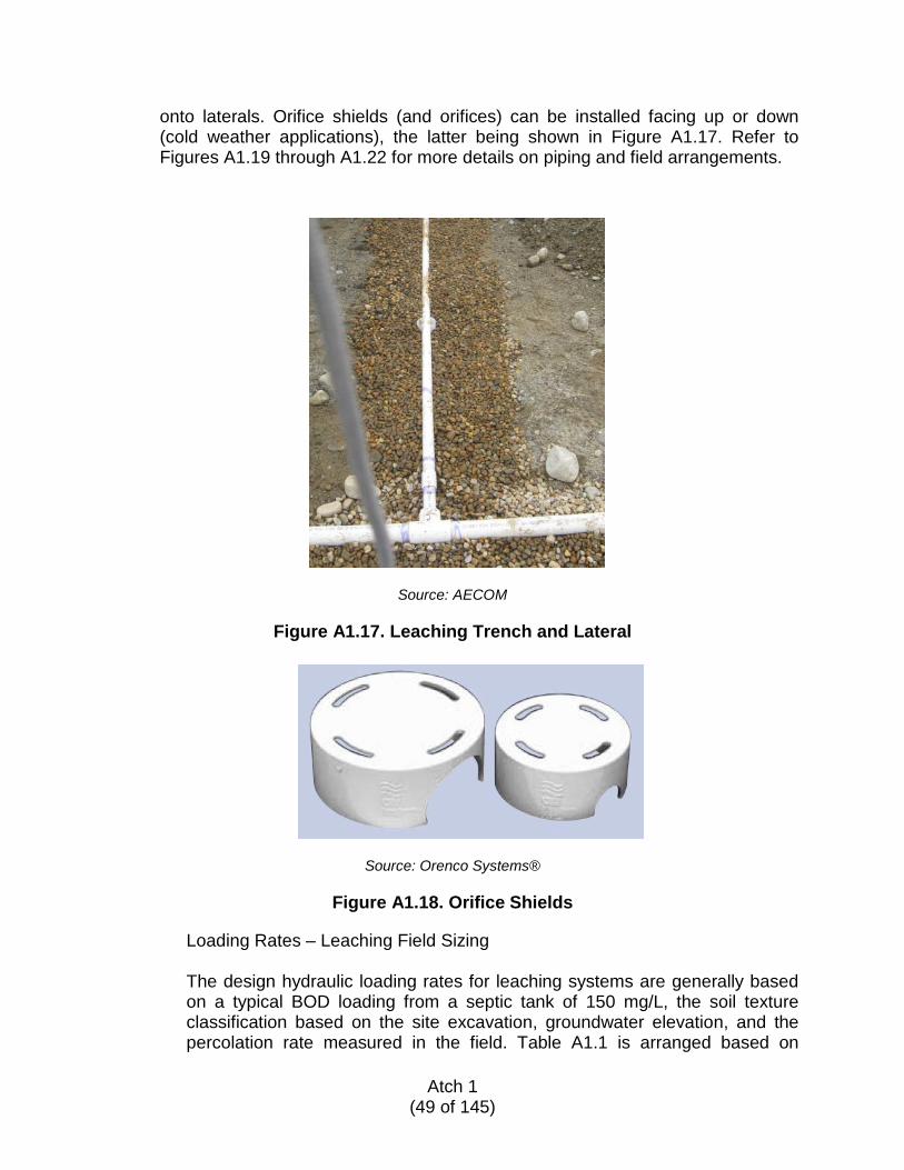
onto laterals. Orifice shields (and orifices) can be installed facing up or down (cold weather applications), the latter being shown in Figure A1.17. Refer to Figures A1.19 through A1.22 for more details on piping and field arrangements.
Source: AECOM
Figure A1.17. Leaching Trench and Lateral
Source: Orenco Systems®
Figure A1.18. Orifice Shields
Loading Rates – Leaching Field Sizing The design hydraulic loading rates for leaching systems are generally based on a typical BOD loading from a septic tank of 150 mg/L, the soil texture classification based on the site excavation, groundwater elevation, and the percolation rate measured in the field. Table A1.1 is arranged based on
Atch 1
(49 of 145)

percolation rate and soil textural class as identified in the site evaluation description in paragraph A1.3.3.1. In Table A1.1, the loading rate has been adjusted to account for the long-term acceptance rate (LTAR) of the leaching field, which is limited in part by the texture of the soil layers under the field and the formation of a biomat based on the strength of effluent applied to the soil. Where significant increased BOD strength is expected, the loading rate may need to be adjusted. For this comparison, Table A1.2 should be consulted. An example is presented in the following paragraph that outlines the design process.
Atch 1
(50 of 145)
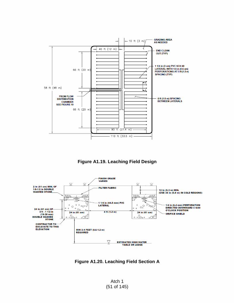
Figure A1.19. Leaching Field Design
Figure A1.20. Leaching Field Section A
Atch 1
(51 of 145)
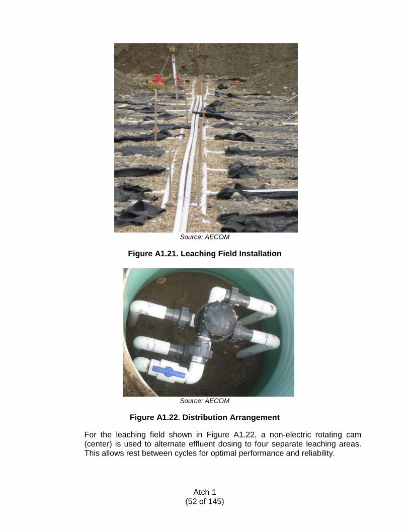
Source: AECOM
Figure A1.21. Leaching Field Installation
Source: AECOM
Figure A1.22. Distribution Arrangement
For the leaching field shown in Figure A1.22, a non-electric rotating cam (center) is used to alternate effluent dosing to four separate leaching areas. This allows rest between cycles for optimal performance and reliability.
Atch 1
(52 of 145)
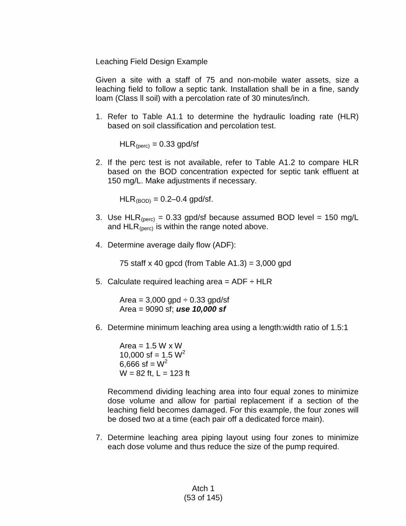
Leaching Field Design Example
Given a site with a staff of 75 and non-mobile water assets, size a leaching field to follow a septic tank. Installation shall be in a fine, sandy loam (Class ll soil) with a percolation rate of 30 minutes/inch.
1. Refer to Table A1.1 to determine the hydraulic loading rate (HLR)
based on soil classification and percolation test.
HLR(perc) = 0.33 gpd/sf
2. If the perc test is not available, refer to Table A1.2 to compare HLR based on the BOD concentration expected for septic tank effluent at 150 mg/L. Make adjustments if necessary.
HLR(BOD) = 0.2–0.4 gpd/sf.
3. Use HLR(perc) = 0.33 gpd/sf because assumed BOD level = 150 mg/L
and HLR(perc) is within the range noted above.
4. Determine average daily flow (ADF):
75 staff x 40 gpcd (from Table A1.3) = 3,000 gpd
5. Calculate required leaching area = ADF ÷ HLR
Area = 3,000 gpd ÷ 0.33 gpd/sf Area = 9090 sf; use 10,000 sf
6. Determine minimum leaching area using a length:width ratio of 1.5:1
Area = 1.5 W x W 10,000 sf = 1.5 W2 6,666 sf = W2 W = 82 ft, L = 123 ft
Recommend dividing leaching area into four equal zones to minimize dose volume and allow for partial replacement if a section of the leaching field becomes damaged. For this example, the four zones will be dosed two at a time (each pair off a dedicated force main).
7. Determine leaching area piping layout using four zones to minimize
each dose volume and thus reduce the size of the pump required.
Atch 1
(53 of 145)
Minimum area for each zone = ¼ (10,000); or each with dimensions 41 ft x 61.5 ft. To keep lateral length within 40 feet and simplify spacing:
Four zones, each: 40 ft W x 66 ft L
8. Calculate number and size of the laterals required for effluent
distribution in each zone:
Lateral spacing = 6 ft on center; 11 laterals required per zone Orifice openings are 0.25 inch and spaced at 5 ft (staggered), eight per lateral
9. Total area required for this system includes 10-foot grading buffer
around perimeter, 6-foot spacing between zones along the length, and 10 foot spacing for installing two parallel distribution header lines to the zones, as shown in Figure A1.19.
A1.5.2.4. Equipment List
The following is a list of equipment to construct a conventional septic tank and leaching field system as described above and designed for 3,000 gpd (11,360 Lpd).
Atch 1
(54 of 145)
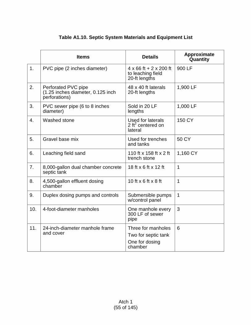
Table A1.10. Septic System Materials and Equipment List
Items Details Approximate Quantity
1. PVC pipe (2 inches diameter) 4 x 66 ft + 2 x 200 ft to leaching field 20-ft lengths
900 LF
2. Perforated PVC pipe (1.25 inches diameter, 0.125 inch perforations)
48 x 40 ft laterals 20-ft lengths
1,900 LF
3. PVC sewer pipe (6 to 8 inches diameter)
Sold in 20 LF lengths
1,000 LF
4. Washed stone Used for laterals 2 ft2 centered on lateral
150 CY
5. Gravel base mix Used for trenches and tanks
50 CY
6. Leaching field sand 110 ft x 158 ft x 2 ft trench stone
1,160 CY
7. 8,000-gallon dual chamber concrete septic tank
18 ft x 6 ft x 12 ft 1
8. 4,500-gallon effluent dosing chamber
10 ft x 6 ft x 8 ft 1
9. Duplex dosing pumps and controls Submersible pumps w/control panel
1
10. 4-foot-diameter manholes One manhole every 300 LF of sewer pipe
3
11. 24-inch-diameter manhole frame and cover
Three for manholes Two for septic tank One for dosing chamber
6
Atch 1
(55 of 145)
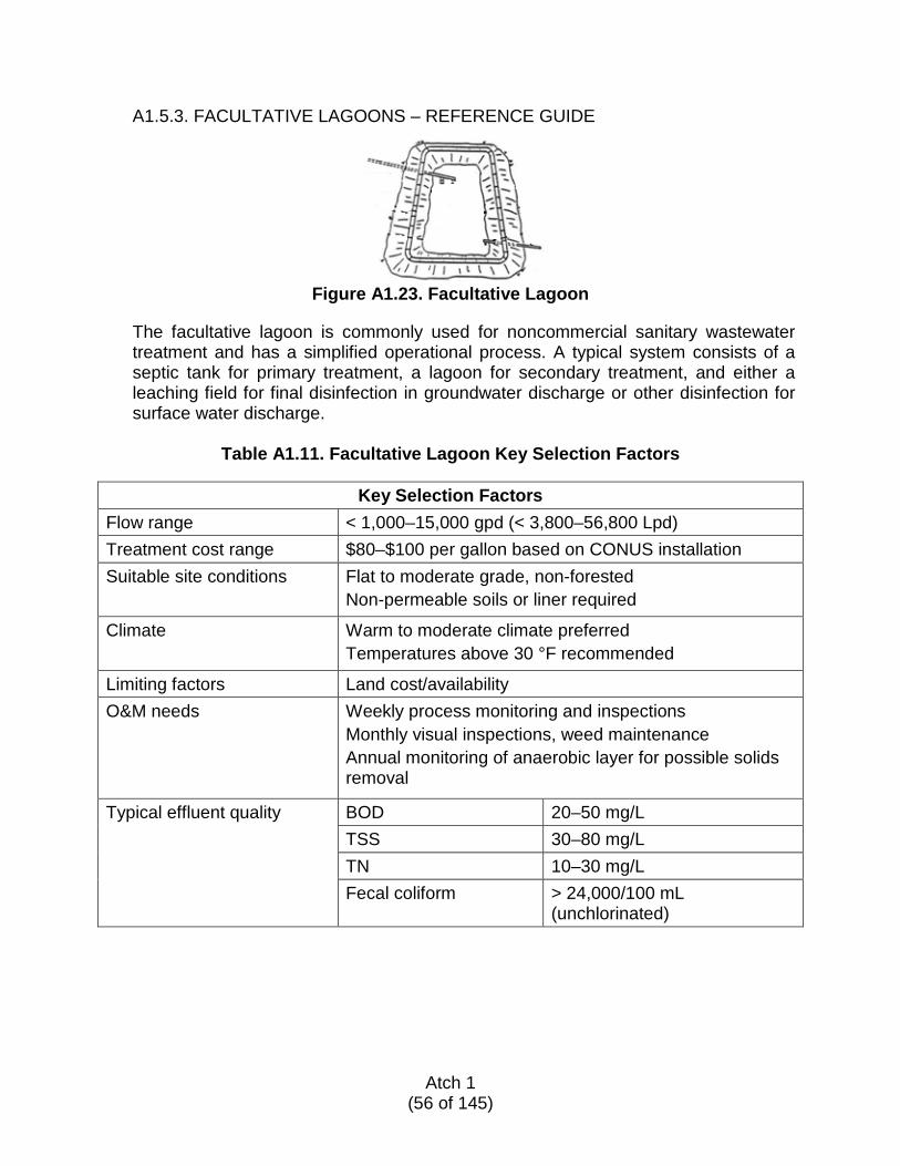
A1.5.3. FACULTATIVE LAGOONS – REFERENCE GUIDE
Figure A1.23. Facultative Lagoon
The facultative lagoon is commonly used for noncommercial sanitary wastewater treatment and has a simplified operational process. A typical system consists of a septic tank for primary treatment, a lagoon for secondary treatment, and either a leaching field for final disinfection in groundwater discharge or other disinfection for surface water discharge.
Table A1.11. Facultative Lagoon Key Selection Factors
Key Selection Factors
Flow range < 1,000–15,000 gpd (< 3,800–56,800 Lpd) Treatment cost range $80–$100 per gallon based on CONUS installation Suitable site conditions Flat to moderate grade, non-forested
Non-permeable soils or liner required
Climate Warm to moderate climate preferred Temperatures above 30 °F recommended
Limiting factors Land cost/availability O&M needs Weekly process monitoring and inspections
Monthly visual inspections, weed maintenance Annual monitoring of anaerobic layer for possible solids removal
Typical effluent quality BOD 20–50 mg/L TSS 30–80 mg/L TN 10–30 mg/L Fecal coliform > 24,000/100 mL
(unchlorinated)
Atch 1
(56 of 145)
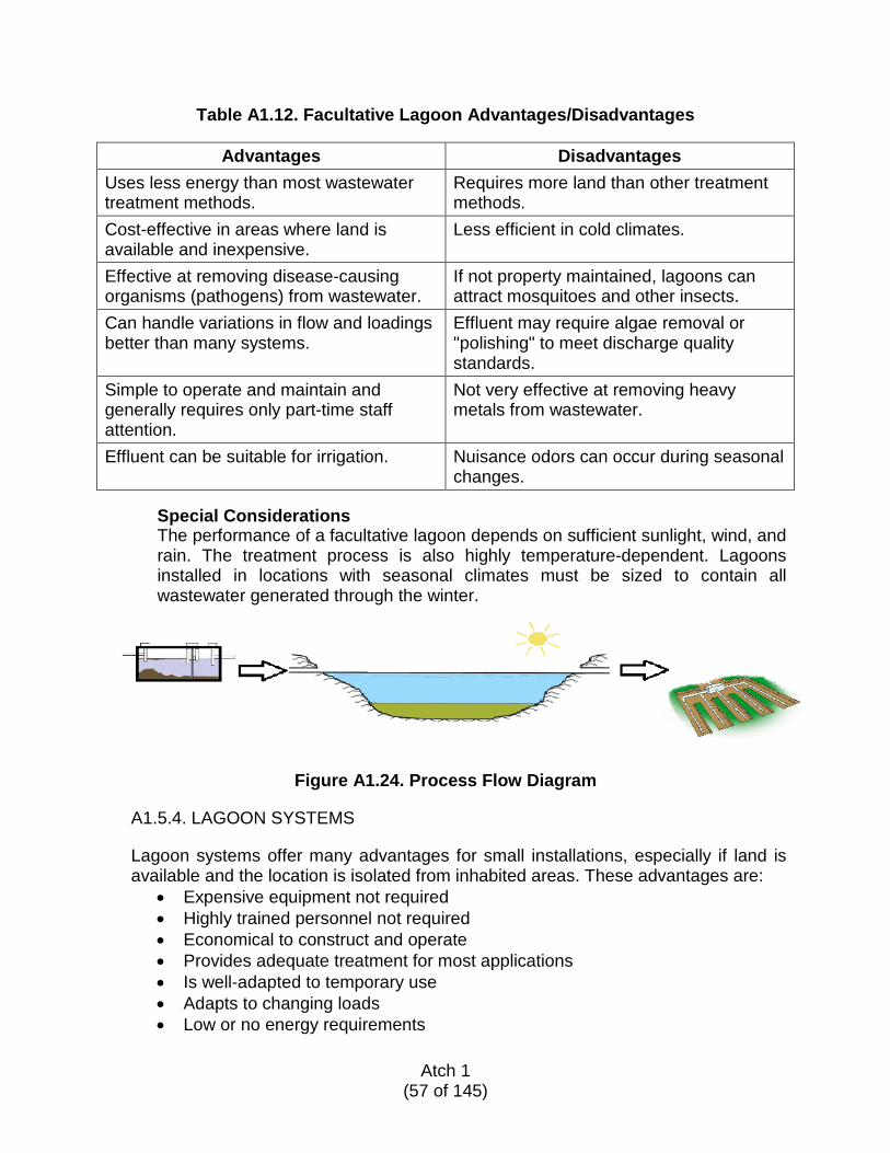
Table A1.12. Facultative Lagoon Advantages/Disadvantages
Advantages Disadvantages Uses less energy than most wastewater treatment methods.
Requires more land than other treatment methods.
Cost-effective in areas where land is available and inexpensive.
Less efficient in cold climates.
Effective at removing disease-causing organisms (pathogens) from wastewater.
If not property maintained, lagoons can attract mosquitoes and other insects.
Can handle variations in flow and loadings better than many systems.
Effluent may require algae removal or "polishing" to meet discharge quality standards.
Simple to operate and maintain and generally requires only part-time staff attention.
Not very effective at removing heavy metals from wastewater.
Effluent can be suitable for irrigation. Nuisance odors can occur during seasonal changes.
Special Considerations The performance of a facultative lagoon depends on sufficient sunlight, wind, and rain. The treatment process is also highly temperature-dependent. Lagoons installed in locations with seasonal climates must be sized to contain all wastewater generated through the winter.
Figure A1.24. Process Flow Diagram
A1.5.4. LAGOON SYSTEMS
Lagoon systems offer many advantages for small installations, especially if land is available and the location is isolated from inhabited areas. These advantages are:
• Expensive equipment not required • Highly trained personnel not required • Economical to construct and operate • Provides adequate treatment for most applications • Is well-adapted to temporary use • Adapts to changing loads • Low or no energy requirements
Atch 1
(57 of 145)
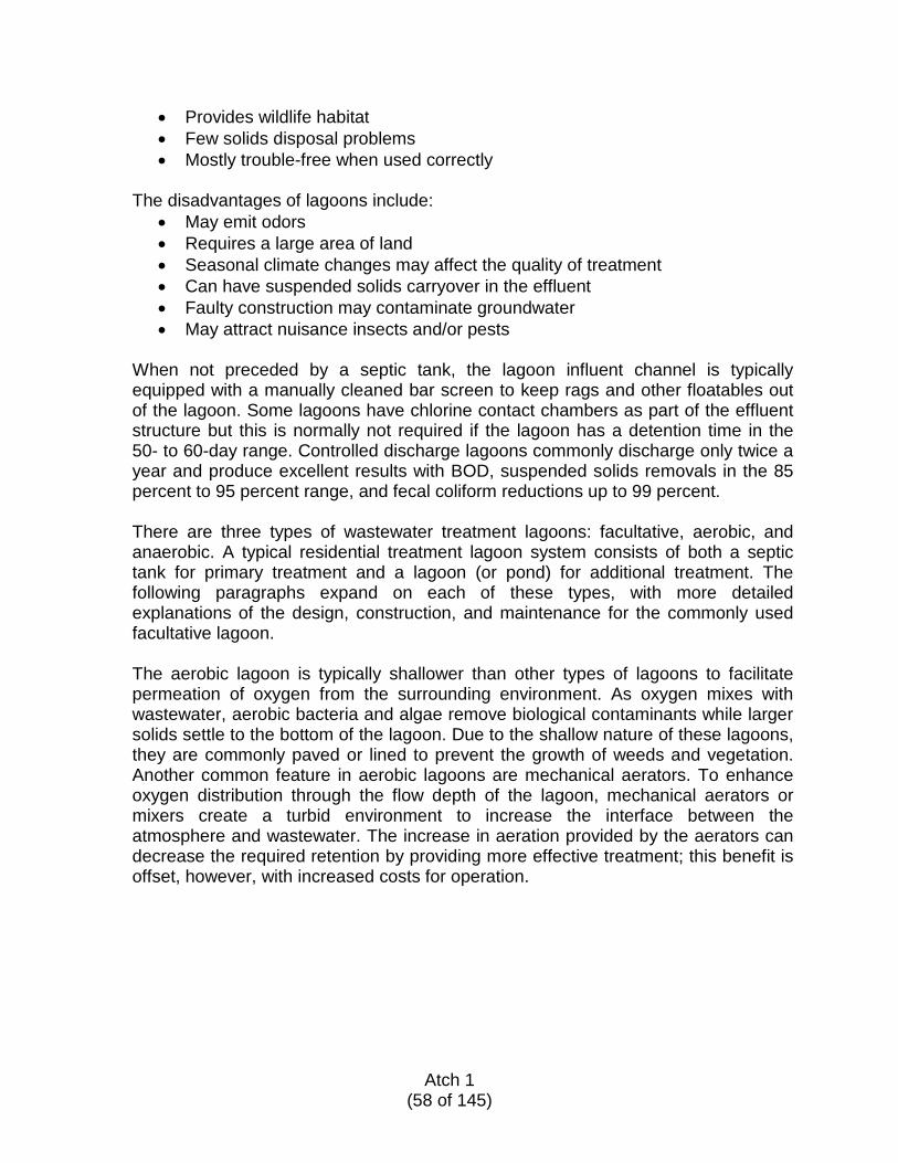
• Provides wildlife habitat • Few solids disposal problems • Mostly trouble-free when used correctly
The disadvantages of lagoons include:
• May emit odors • Requires a large area of land • Seasonal climate changes may affect the quality of treatment • Can have suspended solids carryover in the effluent • Faulty construction may contaminate groundwater • May attract nuisance insects and/or pests
When not preceded by a septic tank, the lagoon influent channel is typically equipped with a manually cleaned bar screen to keep rags and other floatables out of the lagoon. Some lagoons have chlorine contact chambers as part of the effluent structure but this is normally not required if the lagoon has a detention time in the 50- to 60-day range. Controlled discharge lagoons commonly discharge only twice a year and produce excellent results with BOD, suspended solids removals in the 85 percent to 95 percent range, and fecal coliform reductions up to 99 percent. There are three types of wastewater treatment lagoons: facultative, aerobic, and anaerobic. A typical residential treatment lagoon system consists of both a septic tank for primary treatment and a lagoon (or pond) for additional treatment. The following paragraphs expand on each of these types, with more detailed explanations of the design, construction, and maintenance for the commonly used facultative lagoon.
The aerobic lagoon is typically shallower than other types of lagoons to facilitate permeation of oxygen from the surrounding environment. As oxygen mixes with wastewater, aerobic bacteria and algae remove biological contaminants while larger solids settle to the bottom of the lagoon. Due to the shallow nature of these lagoons, they are commonly paved or lined to prevent the growth of weeds and vegetation. Another common feature in aerobic lagoons are mechanical aerators. To enhance oxygen distribution through the flow depth of the lagoon, mechanical aerators or mixers create a turbid environment to increase the interface between the atmosphere and wastewater. The increase in aeration provided by the aerators can decrease the required retention by providing more effective treatment; this benefit is offset, however, with increased costs for operation.
Atch 1
(58 of 145)
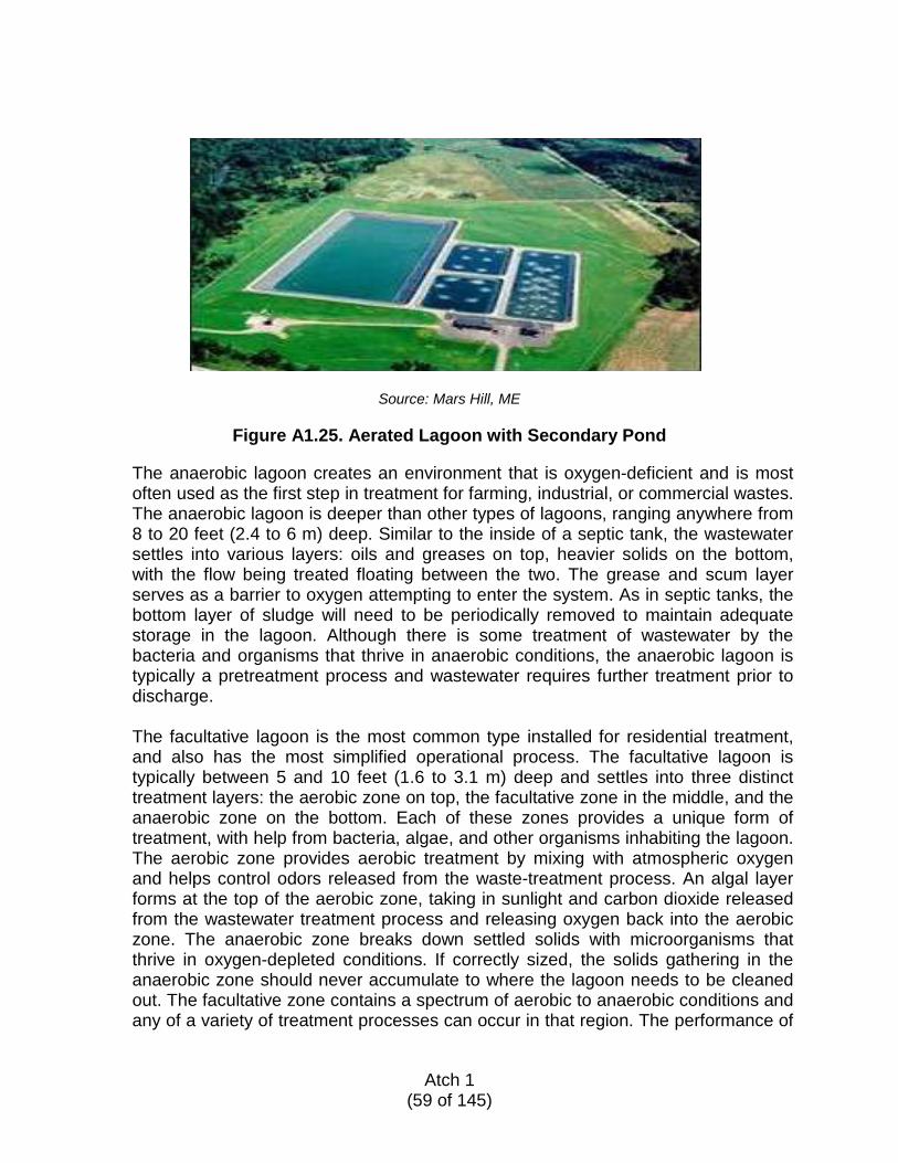
Source: Mars Hill, ME
Figure A1.25. Aerated Lagoon with Secondary Pond
The anaerobic lagoon creates an environment that is oxygen-deficient and is most often used as the first step in treatment for farming, industrial, or commercial wastes. The anaerobic lagoon is deeper than other types of lagoons, ranging anywhere from 8 to 20 feet (2.4 to 6 m) deep. Similar to the inside of a septic tank, the wastewater settles into various layers: oils and greases on top, heavier solids on the bottom, with the flow being treated floating between the two. The grease and scum layer serves as a barrier to oxygen attempting to enter the system. As in septic tanks, the bottom layer of sludge will need to be periodically removed to maintain adequate storage in the lagoon. Although there is some treatment of wastewater by the bacteria and organisms that thrive in anaerobic conditions, the anaerobic lagoon is typically a pretreatment process and wastewater requires further treatment prior to discharge. The facultative lagoon is the most common type installed for residential treatment, and also has the most simplified operational process. The facultative lagoon is typically between 5 and 10 feet (1.6 to 3.1 m) deep and settles into three distinct treatment layers: the aerobic zone on top, the facultative zone in the middle, and the anaerobic zone on the bottom. Each of these zones provides a unique form of treatment, with help from bacteria, algae, and other organisms inhabiting the lagoon. The aerobic zone provides aerobic treatment by mixing with atmospheric oxygen and helps control odors released from the waste-treatment process. An algal layer forms at the top of the aerobic zone, taking in sunlight and carbon dioxide released from the wastewater treatment process and releasing oxygen back into the aerobic zone. The anaerobic zone breaks down settled solids with microorganisms that thrive in oxygen-depleted conditions. If correctly sized, the solids gathering in the anaerobic zone should never accumulate to where the lagoon needs to be cleaned out. The facultative zone contains a spectrum of aerobic to anaerobic conditions and any of a variety of treatment processes can occur in that region. The performance of
Atch 1
(59 of 145)
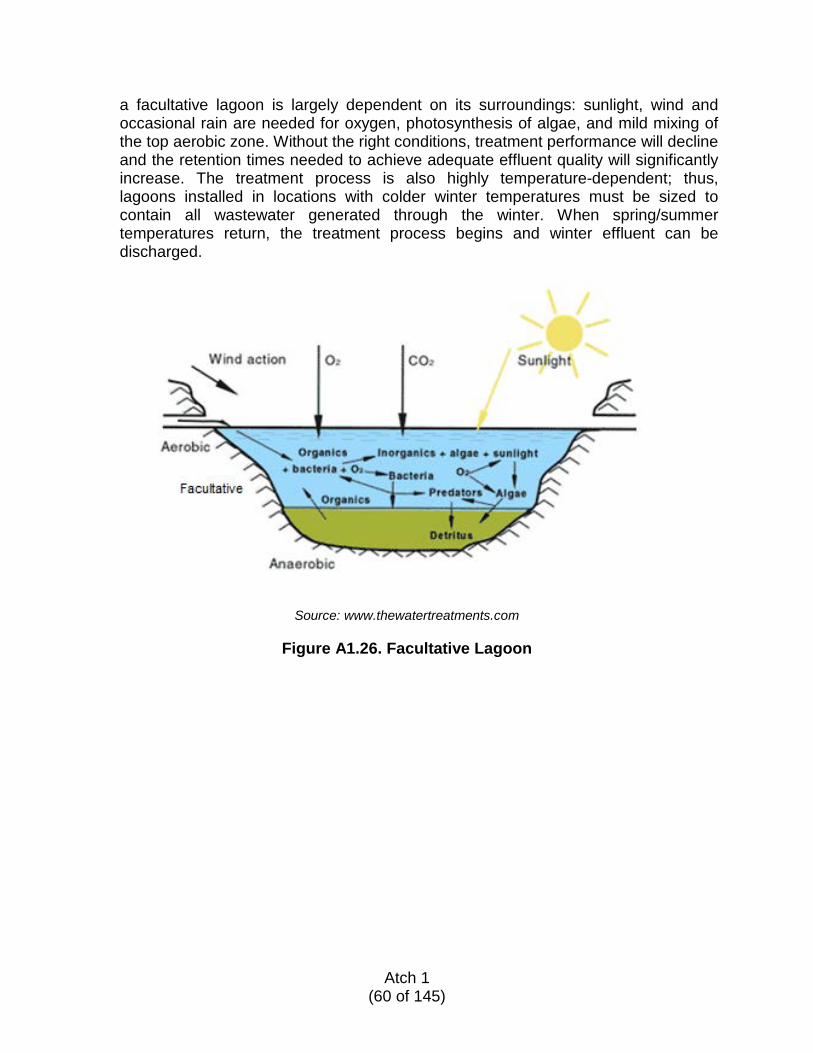
a facultative lagoon is largely dependent on its surroundings: sunlight, wind and occasional rain are needed for oxygen, photosynthesis of algae, and mild mixing of the top aerobic zone. Without the right conditions, treatment performance will decline and the retention times needed to achieve adequate effluent quality will significantly increase. The treatment process is also highly temperature-dependent; thus, lagoons installed in locations with colder winter temperatures must be sized to contain all wastewater generated through the winter. When spring/summer temperatures return, the treatment process begins and winter effluent can be discharged.
Source: www.thewatertreatments.com
Figure A1.26. Facultative Lagoon
Atch 1
(60 of 145)
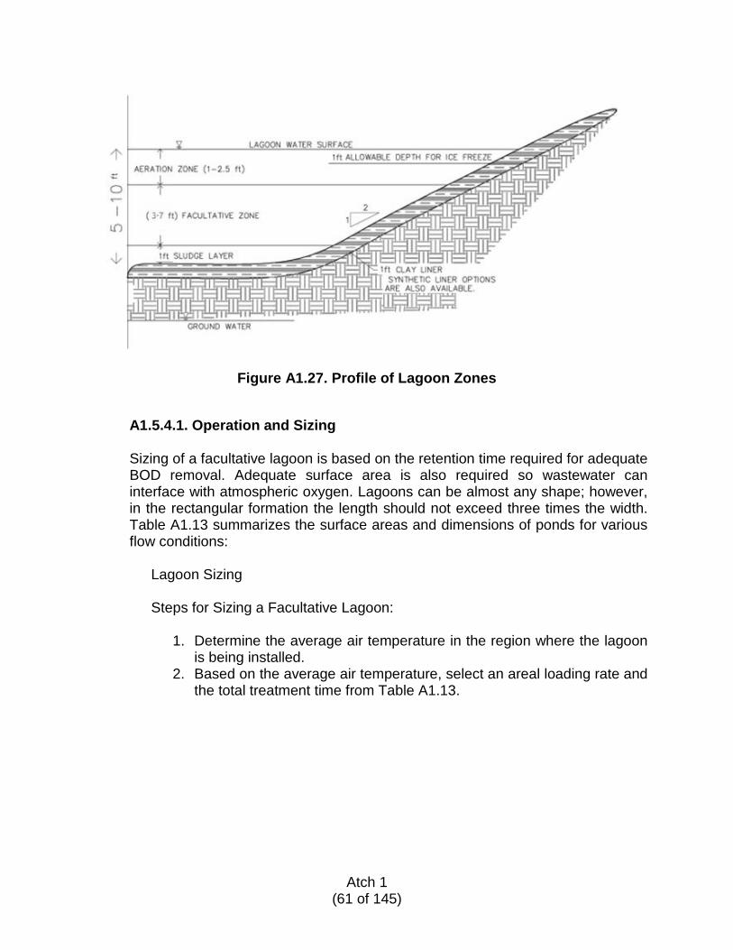
Figure A1.27. Profile of Lagoon Zones
A1.5.4.1. Operation and Sizing
Sizing of a facultative lagoon is based on the retention time required for adequate BOD removal. Adequate surface area is also required so wastewater can interface with atmospheric oxygen. Lagoons can be almost any shape; however, in the rectangular formation the length should not exceed three times the width. Table A1.13 summarizes the surface areas and dimensions of ponds for various flow conditions:
Lagoon Sizing
Steps for Sizing a Facultative Lagoon:
1. Determine the average air temperature in the region where the lagoon
is being installed. 2. Based on the average air temperature, select an areal loading rate and
the total treatment time from Table A1.13.
Atch 1
(61 of 145)
Table A1.13. Areal Loading Rates
Average Air Temperature Areal Loading Rate Total Treatment Time < 0 °C (< 32 °F) 11–22 kg/ha/d
(9.8-19.6 lb/ac/d) 150–180 days
0-15 °C (32–59 °F) 22–45 kg/ha/d (19.6–40 lb/ac/d)
40–150 days
> 15 °C (> 59 °F) 45–90 kg/ha/d (40–80 lb/ac/d)
10–40 days
3. Based on Table A1.3, determine the flow rate into the lagoon. 4. Calculate the BOD loading into the lagoon by multiplying the flow rate
by the BOD concentration. If the BOD concentration is unknown, use 200 mg/L as a standard value.
5. Based on the BOD loading and the areal loading rate, determine the required surface area of the lagoon using the following equation:
Surface area = BOD loading
areal loading rate
6. Determine the dimensions for the surface area of the lagoon. Lagoons
can range from square to rectangular; however, the length should not exceed three times the width for a rectangular lagoon.
7. Based on the flow rate and total treatment time, calculate the total volume required for the lagoon.
Total volume = flow rate × total treatment time
8. Based on the required total volume and the surface area, calculate the
depth of the lagoon.
Depth = total volume ÷ surface area
9. Calculate the total area required for the lagoon by adding additional area for berms, fences, etc.
Example:
Known: Average air temperature = 0–15 °C (59 °F) Flow rate = 3,000 gpd = 11,356.24 Lpd
Example Calculations: Areal loading rate = 22 kg/ha/d Total required retention time = 150 days
Atch 1
(62 of 145)
BOD loading = 11,356.24 Lpd x 200 mg/L x (1 kg ÷ 1,000,000 mg) = 2.27 kg/day Surface area = (2.27 kg/day ÷ 22 kg/[ha/day]) x (10,000 m2 ÷ 1 ha) = 1,032 m2 Length = 3 x width Surface area = length x width = 3 x width2 Width = (surface area)1/2 ÷ (3)1/2 = (1,032 m2)1/2 ÷ (3)1/2 = 18.6 m Length = 3 x 18.6 m = 55.8 m Total volume = (1 m3 ÷ 1,000 L) x 11,356.24 Lpd x 150 days = 1,703 m3 Depth = 1,703 m3 ÷ 1,032 m2 = 1.65 m
Final lagoon dimensions: Length = 55.8 m Width = 18.6 m Depth = 1.65 m
Figure A1.28. Lagoon Design
A1.5.4.2. Selecting Type and Discharge Arrangement
There are various discharge types for facultative lagoons. A continuously discharging lagoon maintains the level of wastewater in the lagoon by discharging at the same rate it is receiving influent flow. In this situation, the most direct flow path must be adequate in length for treatment to occur. A complete retention lagoon (or evaporation lagoon) never releases flow from the containment area, but instead relies on evaporation and percolation to discharge
Atch 1
(63 of 145)
at a rate higher than the influent rate to maintain a constant volume. A controlled discharge lagoon is sized to only discharge once or twice a year. In colder temperatures, a facultative lagoon’s treatment process slows or ceases completely. In a controlled discharging lagoon, the untreated winter flows remain in the lagoon until warmer temperatures return and treatment occurs.
A1.5.4.3. Lining and Maintenance Requirements
Lagoon liner alternatives include compacted clay in locations where low permeable soil conditions are compatible. Where soils are too permeable, synthetic liners such as laminated rubber, polyethylene, or PVC with a minimum thickness of 30 mils (0.03 inch) may be installed over a cushioning layer. Concrete liners are another alternative to consider where O&M issues are anticipated.
Sites suitable for unlined lagoons must have soils with percolation rates of 120 minutes/inch (47 min/cm) or less. Where soils are too permeable, a synthetic liner may be used. The liner should be at least 30-mil (0.03 inch) -thick and is typically made of laminated rubber compounds. Installation may require the services of a professional liner contractor, although homeowner-installable liners are available. To install such a liner, the soil-shaping portion of the lagoon is completed then a layer of sand or geotextile fabric is laid down to protect the liner from rock punctures as it is applied over the cushioning layer. Depending on the manufacturer, seams in the liner may be hot-fused or overlapped, and the ends of the liner material may be anchored in a trench dug in the top of the berms around the perimeter of the lagoon. Not all lagoons require seams; manufacturers sell sheets in sizes as large as 40,000 ft2 (3,700 m2). If PVC is used, the liner must be covered with 12 inches (30.5 cm) of soil to prevent photodegradation and the inside dikes should not exceed a 3:1 slope to prevent slumping of the soil.
A1.5.4.4. Construction Guidelines
When locating a site for the treatment lagoon, it is important to maintain certain setback distances from clean water sources, as summarized in Table A1.14. Lagoons should be sited 50 feet (15.2 m) away from overhanging trees to allow adequate sunlight and keep leaves from falling into the lagoon, adding to the sludge buildup.
Atch 1
(64 of 145)
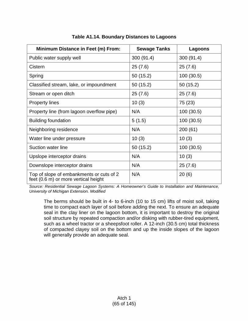
Table A1.14. Boundary Distances to Lagoons
Minimum Distance in Feet (m) From: Sewage Tanks Lagoons
Public water supply well 300 (91.4) 300 (91.4)
Cistern 25 (7.6) 25 (7.6)
Spring 50 (15.2) 100 (30.5)
Classified stream, lake, or impoundment 50 (15.2) 50 (15.2)
Stream or open ditch 25 (7.6) 25 (7.6)
Property lines 10 (3) 75 (23)
Property line (from lagoon overflow pipe) N/A 100 (30.5)
Building foundation 5 (1.5) 100 (30.5)
Neighboring residence N/A 200 (61)
Water line under pressure 10 (3) 10 (3)
Suction water line 50 (15.2) 100 (30.5)
Upslope interceptor drains N/A 10 (3)
Downslope interceptor drains N/A 25 (7.6)
Top of slope of embankments or cuts of 2 feet (0.6 m) or more vertical height
N/A 20 (6)
Source: Residential Sewage Lagoon Systems: A Homeowner’s Guide to Installation and Maintenance, University of Michigan Extension. Modified
The berms should be built in 4- to 6-inch (10 to 15 cm) lifts of moist soil, taking time to compact each layer of soil before adding the next. To ensure an adequate seal in the clay liner on the lagoon bottom, it is important to destroy the original soil structure by repeated compaction and/or disking with rubber-tired equipment, such as a wheel tractor or a sheepsfoot roller. A 12-inch (30.5 cm) total thickness of compacted clayey soil on the bottom and up the inside slopes of the lagoon will generally provide an adequate seal.
Atch 1
(65 of 145)
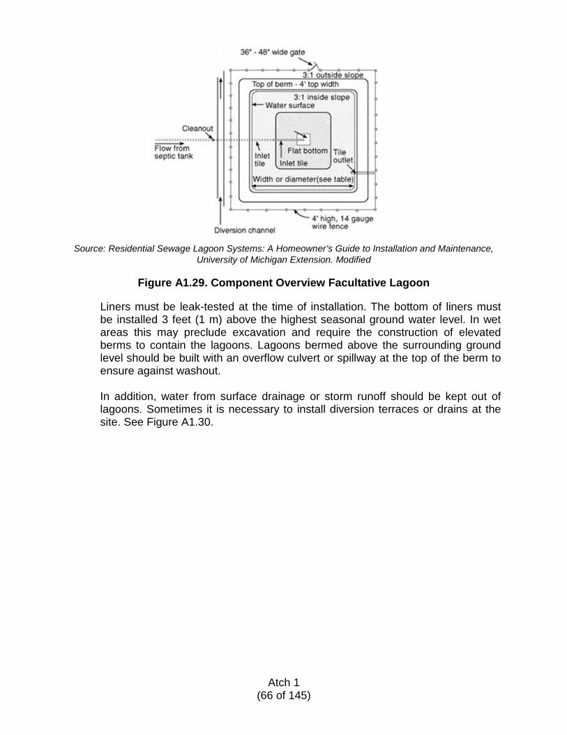
Source: Residential Sewage Lagoon Systems: A Homeowner’s Guide to Installation and Maintenance, University of Michigan Extension. Modified
Figure A1.29. Component Overview Facultative Lagoon
Liners must be leak-tested at the time of installation. The bottom of liners must be installed 3 feet (1 m) above the highest seasonal ground water level. In wet areas this may preclude excavation and require the construction of elevated berms to contain the lagoons. Lagoons bermed above the surrounding ground level should be built with an overflow culvert or spillway at the top of the berm to ensure against washout.
In addition, water from surface drainage or storm runoff should be kept out of lagoons. Sometimes it is necessary to install diversion terraces or drains at the site. See Figure A1.30.
Atch 1
(66 of 145)
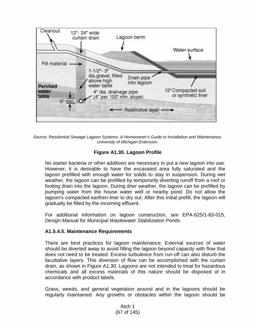
Source: Residential Sewage Lagoon Systems: A Homeowner’s Guide to Installation and Maintenance, University of Michigan Extension.
Figure A1.30. Lagoon Profile
No starter bacteria or other additives are necessary to put a new lagoon into use. However, it is desirable to have the excavated area fully saturated and the lagoon prefilled with enough water for solids to stay in suspension. During wet weather, the lagoon can be prefilled by temporarily diverting runoff from a roof or footing drain into the lagoon. During drier weather, the lagoon can be prefilled by pumping water from the house water well or nearby pond. Do not allow the lagoon's compacted earthen liner to dry out. After this initial prefill, the lagoon will gradually be filled by the incoming effluent. For additional information on lagoon construction, see EPA-625/1-83-015, Design Manual for Municipal Wastewater Stabilization Ponds.
A1.5.4.5. Maintenance Requirements
There are best practices for lagoon maintenance. External sources of water should be diverted away to avoid filling the lagoon beyond capacity with flow that does not need to be treated. Excess turbulence from run-off can also disturb the facultative layers. This diversion of flow can be accomplished with the curtain drain, as shown in Figure A1.30. Lagoons are not intended to treat for hazardous chemicals and all excess materials of this nature should be disposed of in accordance with product labels. Grass, weeds, and general vegetation around and in the lagoons should be regularly maintained. Any growths or obstacles within the lagoon should be
Atch 1
(67 of 145)
removed so as not to disturb the flow pattern and create short-circuiting or “dead-spots.” Blue-green algae must also be removed to maintain the health of the lagoon. Algal blooms can occur when the desirable green algae reproduces rapidly in response to changes in weather and then dies off, creating odors and clouding. Foul odors can be released during the changing seasons, as changing temperatures within the facultative layers cause the anaerobic layer to rise as the aerobic layer sinks. The anaerobic layer should also be monitored yearly for thickness and removed as necessary.
For additional information, refer to paragraph A1.8.2 of this ETL and UFC 3-240-02, Domestic Wastewater Treatment.
A1.5.4.6. Equipment List
Table A1.15 provides a list of equipment necessary to install a lagoon system sized for 3,000 gpd (11,360 Lpd), as designed in this example.
Atch 1
(68 of 145)
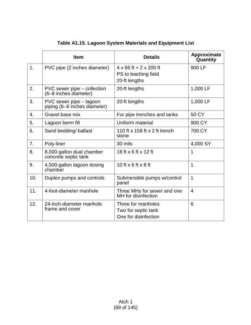
Table A1.15. Lagoon System Materials and Equipment List Item Details Approximate
Quantity 1. PVC pipe (2 inches diameter) 4 x 66 ft + 2 x 200 ft
PS to leaching field 20-ft lengths
900 LF
2. PVC sewer pipe – collection (6–8 inches diameter)
20-ft lengths 1,000 LF
3. PVC sewer pipe – lagoon piping (6–8 inches diameter)
20-ft lengths 1,000 LF
4. Gravel base mix For pipe trenches and tanks 50 CY 5. Lagoon berm fill Uniform material 900 CY 6. Sand bedding/ ballast 110 ft x 158 ft x 2 ft trench
stone 700 CY
7. Poly-liner 30 mils 4,000 SY 8. 8,000-gallon dual chamber
concrete septic tank 18 ft x 6 ft x 12 ft 1
9. 4,500-gallon lagoon dosing chamber
10 ft x 6 ft x 8 ft 1
10. Duplex pumps and controls Submersible pumps w/control panel
1
11. 4-foot-diameter manhole Three MHs for sewer and one MH for disinfection
4
12. 24-inch-diameter manhole frame and cover
Three for manholes Two for septic tank One for disinfection
6
Atch 1
(69 of 145)
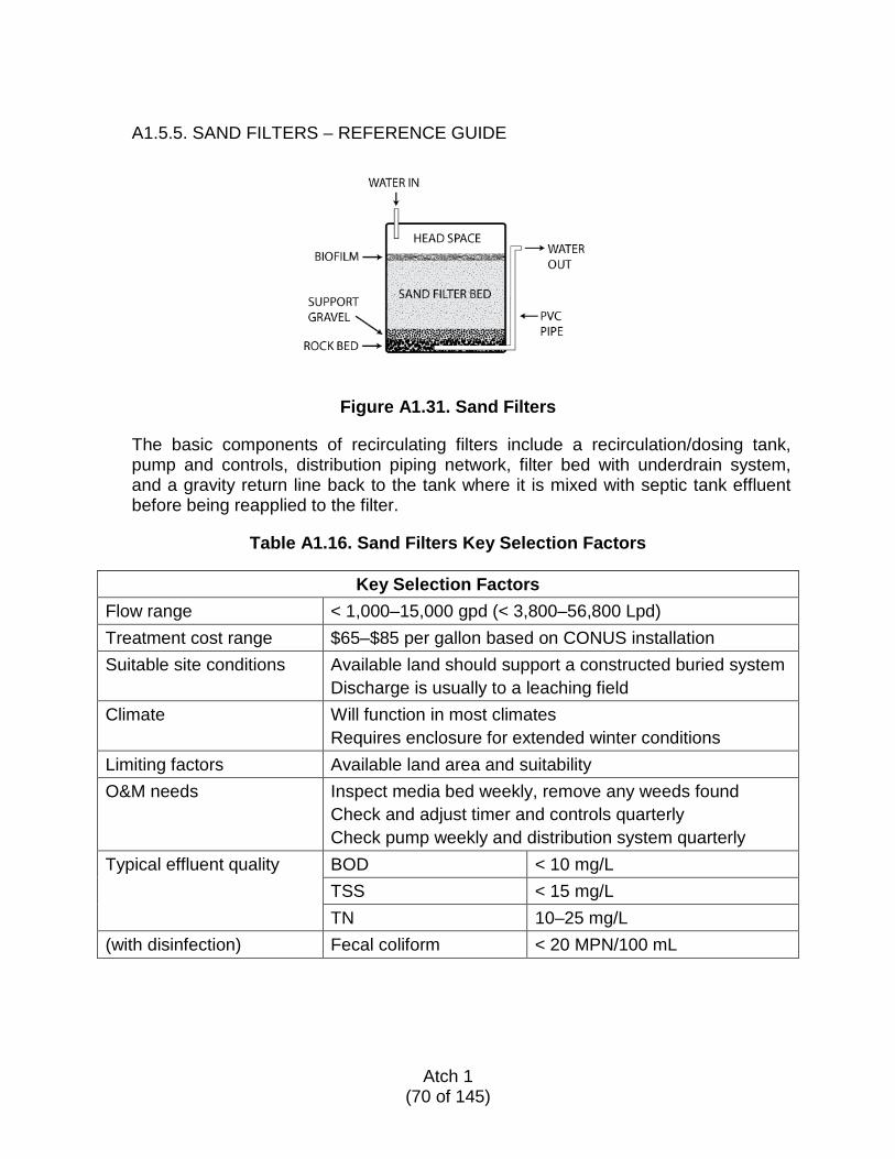
A1.5.5. SAND FILTERS – REFERENCE GUIDE
Figure A1.31. Sand Filters
The basic components of recirculating filters include a recirculation/dosing tank, pump and controls, distribution piping network, filter bed with underdrain system, and a gravity return line back to the tank where it is mixed with septic tank effluent before being reapplied to the filter.
Table A1.16. Sand Filters Key Selection Factors
Key Selection Factors
Flow range < 1,000–15,000 gpd (< 3,800–56,800 Lpd) Treatment cost range $65–$85 per gallon based on CONUS installation Suitable site conditions Available land should support a constructed buried system
Discharge is usually to a leaching field Climate Will function in most climates
Requires enclosure for extended winter conditions Limiting factors Available land area and suitability O&M needs Inspect media bed weekly, remove any weeds found
Check and adjust timer and controls quarterly Check pump weekly and distribution system quarterly
Typical effluent quality BOD < 10 mg/L TSS < 15 mg/L TN 10–25 mg/L (with disinfection) Fecal coliform < 20 MPN/100 mL
Atch 1
(70 of 145)
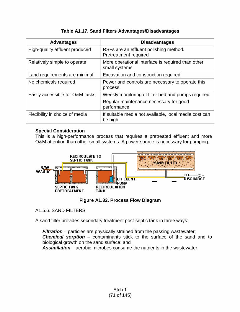
Table A1.17. Sand Filters Advantages/Disadvantages
Advantages Disadvantages High-quality effluent produced RSFs are an effluent polishing method.
Pretreatment required Relatively simple to operate More operational interface is required than other
small systems Land requirements are minimal Excavation and construction required No chemicals required Power and controls are necessary to operate this
process. Easily accessible for O&M tasks Weekly monitoring of filter bed and pumps required Regular maintenance necessary for good
performance Flexibility in choice of media If suitable media not available, local media cost can
be high
Special Consideration This is a high-performance process that requires a pretreated effluent and more O&M attention than other small systems. A power source is necessary for pumping.
Figure A1.32. Process Flow Diagram
A1.5.6. SAND FILTERS
A sand filter provides secondary treatment post-septic tank in three ways:
Filtration – particles are physically strained from the passing wastewater; Chemical sorption – contaminants stick to the surface of the sand and to biological growth on the sand surface; and Assimilation – aerobic microbes consume the nutrients in the wastewater.
Atch 1
(71 of 145)
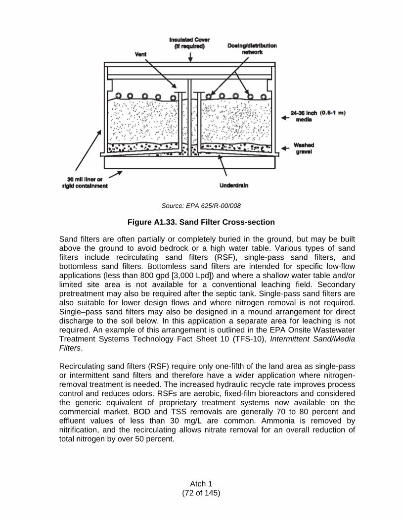
Source: EPA 625/R-00/008
Figure A1.33. Sand Filter Cross-section
Sand filters are often partially or completely buried in the ground, but may be built above the ground to avoid bedrock or a high water table. Various types of sand filters include recirculating sand filters (RSF), single-pass sand filters, and bottomless sand filters. Bottomless sand filters are intended for specific low-flow applications (less than 800 gpd [3,000 Lpd]) and where a shallow water table and/or limited site area is not available for a conventional leaching field. Secondary pretreatment may also be required after the septic tank. Single-pass sand filters are also suitable for lower design flows and where nitrogen removal is not required. Single–pass sand filters may also be designed in a mound arrangement for direct discharge to the soil below. In this application a separate area for leaching is not required. An example of this arrangement is outlined in the EPA Onsite Wastewater Treatment Systems Technology Fact Sheet 10 (TFS-10), Intermittent Sand/Media Filters. Recirculating sand filters (RSF) require only one-fifth of the land area as single-pass or intermittent sand filters and therefore have a wider application where nitrogen-removal treatment is needed. The increased hydraulic recycle rate improves process control and reduces odors. RSFs are aerobic, fixed-film bioreactors and considered the generic equivalent of proprietary treatment systems now available on the commercial market. BOD and TSS removals are generally 70 to 80 percent and effluent values of less than 30 mg/L are common. Ammonia is removed by nitrification, and the recirculating allows nitrate removal for an overall reduction of total nitrogen by over 50 percent.
Atch 1
(72 of 145)
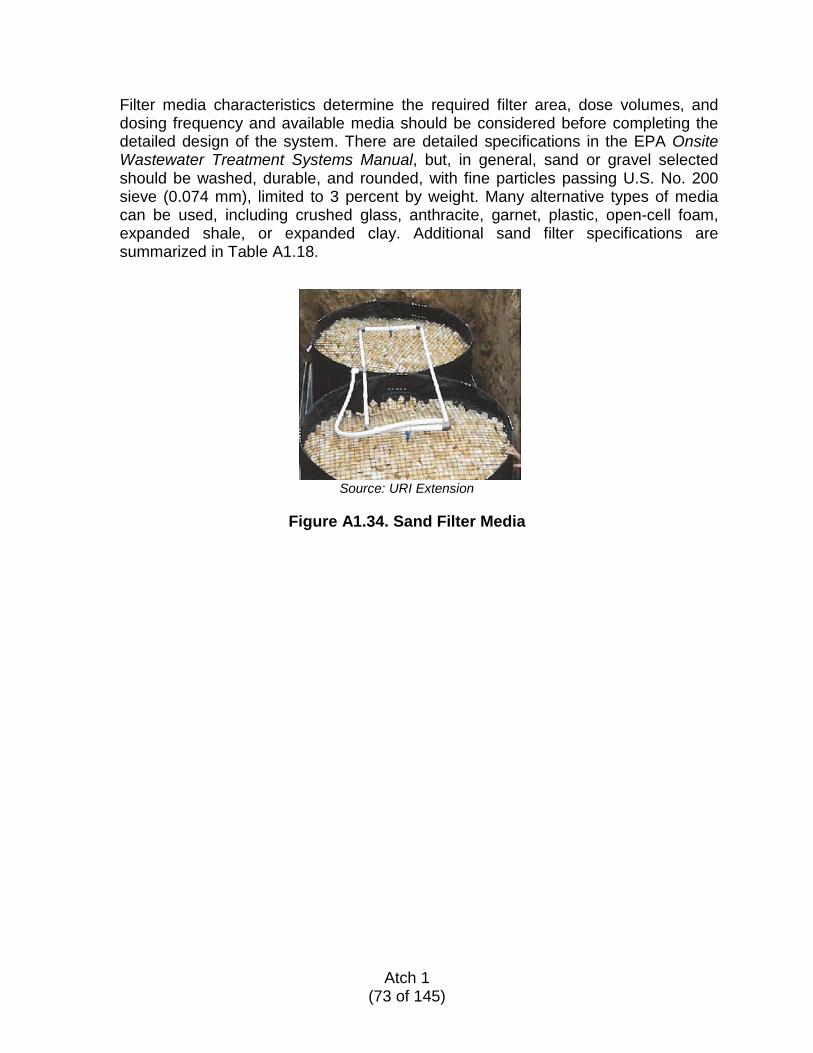
Filter media characteristics determine the required filter area, dose volumes, and dosing frequency and available media should be considered before completing the detailed design of the system. There are detailed specifications in the EPA Onsite Wastewater Treatment Systems Manual, but, in general, sand or gravel selected should be washed, durable, and rounded, with fine particles passing U.S. No. 200 sieve (0.074 mm), limited to 3 percent by weight. Many alternative types of media can be used, including crushed glass, anthracite, garnet, plastic, open-cell foam, expanded shale, or expanded clay. Additional sand filter specifications are summarized in Table A1.18.
Source: URI Extension
Figure A1.34. Sand Filter Media
Atch 1
(73 of 145)
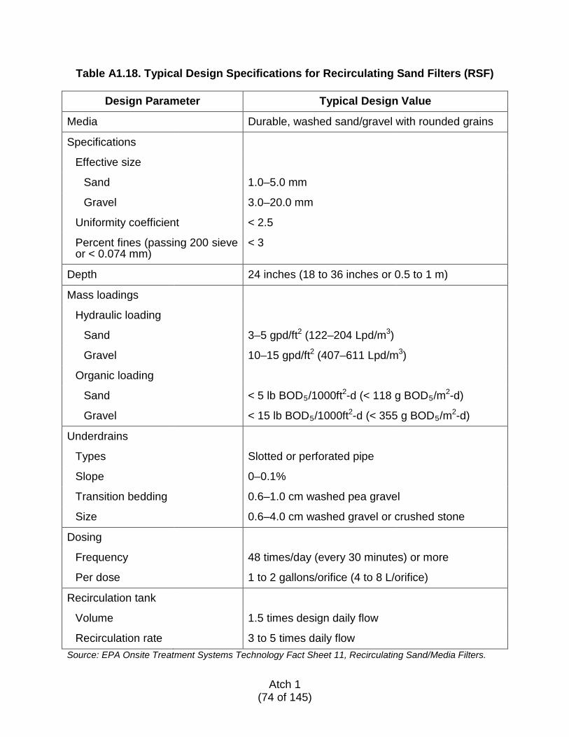
Table A1.18. Typical Design Specifications for Recirculating Sand Filters (RSF)
Design Parameter Typical Design Value
Media Durable, washed sand/gravel with rounded grains
Specifications
Effective size
Sand 1.0–5.0 mm
Gravel 3.0–20.0 mm
Uniformity coefficient < 2.5
Percent fines (passing 200 sieve or < 0.074 mm)
< 3
Depth 24 inches (18 to 36 inches or 0.5 to 1 m)
Mass loadings
Hydraulic loading
Sand 3–5 gpd/ft2 (122–204 Lpd/m3)
Gravel 10–15 gpd/ft2 (407–611 Lpd/m3)
Organic loading
Sand < 5 lb BOD5/1000ft2-d (< 118 g BOD5/m2-d)
Gravel < 15 lb BOD5/1000ft2-d (< 355 g BOD5/m2-d)
Underdrains
Types Slotted or perforated pipe
Slope 0–0.1%
Transition bedding 0.6–1.0 cm washed pea gravel
Size 0.6–4.0 cm washed gravel or crushed stone
Dosing
Frequency 48 times/day (every 30 minutes) or more
Per dose 1 to 2 gallons/orifice (4 to 8 L/orifice)
Recirculation tank
Volume 1.5 times design daily flow
Recirculation rate 3 to 5 times daily flow Source: EPA Onsite Treatment Systems Technology Fact Sheet 11, Recirculating Sand/Media Filters.
Atch 1
(74 of 145)
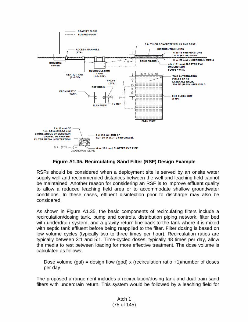
Figure A1.35. Recirculating Sand Filter (RSF) Design Example
RSFs should be considered when a deployment site is served by an onsite water supply well and recommended distances between the well and leaching field cannot be maintained. Another reason for considering an RSF is to improve effluent quality to allow a reduced leaching field area or to accommodate shallow groundwater conditions. In these cases, effluent disinfection prior to discharge may also be considered. As shown in Figure A1.35, the basic components of recirculating filters include a recirculation/dosing tank, pump and controls, distribution piping network, filter bed with underdrain system, and a gravity return line back to the tank where it is mixed with septic tank effluent before being reapplied to the filter. Filter dosing is based on low volume cycles (typically two to three times per hour). Recirculation ratios are typically between 3:1 and 5:1. Time-cycled doses, typically 48 times per day, allow the media to rest between loading for more effective treatment. The dose volume is calculated as follows:
Dose volume (gal) = design flow (gpd) x (recirculation ratio +1)/number of doses per day
The proposed arrangement includes a recirculation/dosing tank and dual train sand filters with underdrain return. This system would be followed by a leaching field for
Atch 1
(75 of 145)
final discharge as shown in Figures A1.19 and A1.20. A detailed design explanation and calculations for the RSF system are shown in paragraph A1.5.6.1.
A1.5.6.1. Recirculating Sand Filter (RSF) Design Procedure
1. Determine the average daily flow (ADF) and the design flow (Q) for the
facility. The ADF is the amount of wastewater to be treated on a daily basis, and may be determined using Table A1.3.
Q = ADF
2. Determine hydraulic loading rate (HLR). The HLR ranges from 3 to 5 gallons
per day per square foot (gpd/ft2), dependent on the media type. For coarse sand like that found in an RSF, use 3 gpd/ft2.
HLR = 3 gpd/ft2 for coarse sand
3. Determine the area required (A).
A (ft2) = ADF/HLR
4. Determine tank dimensions (L x W). Two parallel basins are recommended to
allow alternating dosing. Each basin provides one-half the required area. For each, the length (L) should be 1.5 times the width (W), but not greater than 50 feet.
L = 1.5 x W (ft) or 50 ft, whichever is less A (ft2) = L (ft) x W (ft) x number of basins
5. Determine the recirculation ratio (RR) required. RR is the total flow through
the RSF compared to the design flow. In general, the RR is between 3:1 and 5:1. The higher RR is recommended for a conservative design since higher loading concentrations are expected.
RR = 5:1
6. Determine the influent flow (Qi).
Qi = ADF x (RR +1)
7. Determine doses per day. For a typical design, the number of pump cycles
would be four to eight cycles per hour or every 7.5 to 15 minutes. Use 15-minute intervals to preserve the life of the pump.
Doses per day = 15 minutes x (1 hour ÷ 60 minutes) x (1 day ÷ 24 hours) Doses per day = 96
Atch 1
(76 of 145)
8. Determine dose volume.
Dose volume (gallons) = Qi ÷ (doses per day)
9. Determine the number of laterals required. A lateral is a perforated pipe used
for the even distribution of flow over an area. The number of laterals required is based on the dimensions of the RSF being installed. Laterals shall be spaced 2 feet on center (o.c.) along the width (W) of RSF.
Number of laterals per basin = (width – 2 feet) ÷ 2 feet
10. Lateral size. Laterals shall be made using a 0.75-inch-diameter pipe. Laterals
shall extend from the influent to 1 foot from the opposite wall.
Lateral diameter = 0.75 inch Lateral length = L - 1 foot
11. Orifice size. The laterals shall be perforated with 0.25-inch-diameter orifices.
Orifice diameter = 0.25 inch
12. Orifice spacing.
Orifice spacing = 2 feet o.c. Orifice spacing = 1 foot o.c. at lateral ends
13. Flow through orifice.
Orifice flow ≤ 2 gallons per dose (recommended maximum)
14. Determine number of orifices required.
Number of orifices = dose volume ÷ orifice flow
15. Determine number of orifices per lateral. The orifices are spaced 2 feet o.c.;
therefore, the number of orifices is equal to the length of the lateral minus 2 feet divided by 2 feet.
Orifice per lateral = (length of lateral – 2 feet) ÷ 2 feet.
16. Determine total number of orifices.
Orifice total = orifice per lateral x number of laterals per basin x the number of basins
Atch 1
(77 of 145)
17. Recirculation pump runtime (Tp). Each recirculation pump shall be designed to operate for five minutes per pump cycle. See paragraph A1.7.4.1 for information on sizing the recirculation pump.
Tp = 5 minutes x doses per day ÷ number of pumps
18. Determine flow rate per dose. To determine the flow per dose, divide the
influent flow (Qi) by the total pump runtime (Tp).
Flow per dose (gpm) = Qi ÷ Tp
19. Determine flow rate per orifice. The flow per 0.25-inch orifice should not exceed 0.43 gpm.
Flow per orifice = flow per dose ÷ orifice total
If the flow per orifice is less than or equal to 0.43 gpm then the design is complete. If the flow per orifice is greater than 0.43 gpm, additional orifices are required and the surface area of the RSF basin will need to be increased.
A1.5.6.2. Recirculating Sand Filter (RSF) Design Example
Problem:
Given a site with a staff of 75 and non-mobile water assets, design a two-basin RSF. Recirculation pumps will cycle on and off four times per hour and will run for five minutes upon startup. Given the site conditions and the guidelines provided here on locating septic systems, the maximum width for the RSF that the site can accommodate is 20 feet. Assume a recirculation ratio of 5:1 based on location.
Solution:
ADF = 75 staff x 40 gpcd (from Table A1.3) = 3,000 gallons per day (gpd) Design flow (Q) = ADF = 3,000 gpd
Q= 3,000 gpd
HLR (coarse sand) = 3 gpd/ft2
A = Q/HLR A= 3,000 gpd ÷ 3 gpd/ft2 = 1,000 ft2 A = 1,000 ft2
Two basins; therefore, the area of each basin is: ½ A = 500 ft2
A = L x W
Atch 1
(78 of 145)
500 = L x W Where: W = 20 feet
Solve for L
L = 25 feet
Dimensions of basin: 20 feet x 25 feet
Total amount of flow (Qi):
Qi(gpd) = Q(gpd) x (RR + 1) Qi = 3,000 gpd x 6 Qi = 18,000 gpd
Number of doses per day:
(24 hours/day) x (4 doses/hour) = 96 doses/day
Dose volume (VD):
VD = (18,000 gpd) ÷ (96 doses/day) VD = 188 gallons/dose
Number of laterals per basin = (W - 2) ÷ 2
(20 feet – 2 feet) ÷ 2
Required laterals per basin = 9
Number of orifices = VD ÷ 2 gallons per orifice
Number of orifices = 188 gallons ÷ (2 gallons/orifice) Number of orifices = 94
Number of orifices per lateral = (L - 1) ÷ 2
Orifices = (25 feet – 1 foot) ÷ 2 feet Orifices per lateral = 12
Total number of orifices per basin = 12 orifices/lateral x 9 laterals
Total number of orifices per basin = 108 Two basins ∴ = 216 orifices 216 orifices is > 94, so this is satisfactory
Atch 1
(79 of 145)
Total runtime per day per recirculation pump (TP) = 5 minutes x (96 doses/day ÷ 2 pumps)
TP = 240 minutes/day
Flow per dose provide by the pumps = Qi ÷ (2 x TP)
Flow per dose = (18,000 gpd) ÷ (480 minutes/day) Flow per dose = 75 gpm
Flow per orifice = flow per dose ÷ total number of orifices
75 gpm ÷ 216 orifices Flow per orifice = 0.35 gpm 0.35 gpm ≤ 0.43 gpm (acceptable)
Summary of design:
Provide two basins that are each 20 feet x 25 feet. Each basin shall be equipped with nine 0.75-inch laterals located 2 feet o.c. Each lateral shall have 106 0.25-inch orifice openings located 2 feet o.c.
A1.5.6.3. Equipment List
The following is a list of materials and equipment for installing an RSF for 3,000 gpd (11,360 Lpd), as designed above. Note that this list is only for the RSF and must be combined with the conventional septic system list in Table A1.10. For some installations, the addition of the RSF will allow a reduction of leaching field area by 50 percent.
Atch 1
(80 of 145)
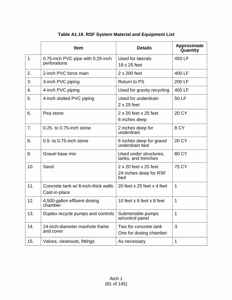
Table A1.19. RSF System Material and Equipment List
Item Details Approximate Quantity
1. 0.75-inch PVC pipe with 0.25-inch perforations
Used for laterals 18 x 25 feet
450 LF
2. 2-inch PVC force main 2 x 200 feet 400 LF
3. 3-inch PVC piping Return to PS 200 LF
4. 4-inch PVC piping Used for gravity recycling 400 LF
5. 4-inch slotted PVC piping Used for underdrain 2 x 25 feet
50 LF
6. Pea stone 2 x 20 feet x 25 feet 6 inches deep
20 CY
7. 0.25- to 0.75-inch stone 2 inches deep for underdrain
8 CY
8. 0.5- to 0.75-inch stone 6 inches deep for gravel underdrain bed
20 CY
9. Gravel base mix Used under structures, tanks, and trenches
80 CY
10. Sand 2 x 20 feet x 25 feet 24 inches deep for RSF bed
75 CY
11. Concrete tank w/ 8-inch-thick walls Cast-in-place
20 feet x 25 feet x 4 feet 1
12. 4,500-gallon effluent dosing chamber
10 feet x 6 feet x 8 feet 1
13. Duplex recycle pumps and controls Submersible pumps w/control panel
1
14. 24-inch-diameter manhole frame and cover
Two for concrete tank One for dosing chamber
3
15. Valves, cleanouts, fittings As necessary 1
Atch 1
(81 of 145)
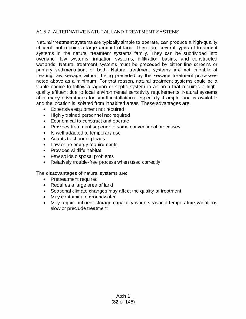
A1.5.7. ALTERNATIVE NATURAL LAND TREATMENT SYSTEMS
Natural treatment systems are typically simple to operate, can produce a high-quality effluent, but require a large amount of land. There are several types of treatment systems in the natural treatment systems family. They can be subdivided into overland flow systems, irrigation systems, infiltration basins, and constructed wetlands. Natural treatment systems must be preceded by either fine screens or primary sedimentation, or both. Natural treatment systems are not capable of treating raw sewage without being preceded by the sewage treatment processes noted above as a minimum. For that reason, natural treatment systems could be a viable choice to follow a lagoon or septic system in an area that requires a high-quality effluent due to local environmental sensitivity requirements. Natural systems offer many advantages for small installations, especially if ample land is available and the location is isolated from inhabited areas. These advantages are:
• Expensive equipment not required • Highly trained personnel not required • Economical to construct and operate • Provides treatment superior to some conventional processes • Is well-adapted to temporary use • Adapts to changing loads • Low or no energy requirements • Provides wildlife habitat • Few solids disposal problems • Relatively trouble-free process when used correctly
The disadvantages of natural systems are:
• Pretreatment required • Requires a large area of land • Seasonal climate changes may affect the quality of treatment • May contaminate groundwater • May require influent storage capability when seasonal temperature variations
slow or preclude treatment
Atch 1
(82 of 145)
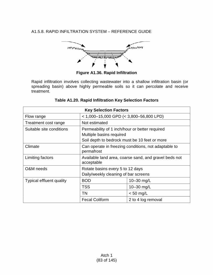
A1.5.8. RAPID INFILTRATION SYSTEM – REFERENCE GUIDE
Figure A1.36. Rapid Infiltration
Rapid infiltration involves collecting wastewater into a shallow infiltration basin (or spreading basin) above highly permeable soils so it can percolate and receive treatment.
Table A1.20. Rapid Infiltration Key Selection Factors
Key Selection Factors
Flow range < 1,000–15,000 GPD (< 3,800–56,800 LPD) Treatment cost range Not estimated Suitable site conditions Permeability of 1 inch/hour or better required
Multiple basins required Soil depth to bedrock must be 10 feet or more
Climate Can operate in freezing conditions, not adaptable to permafrost
Limiting factors Available land area, coarse sand, and gravel beds not acceptable
O&M needs Rotate basins every 5 to 12 days Daily/weekly cleaning of bar screens
Typical effluent quality BOD 10–30 mg/L TSS 10–30 mg/L TN < 50 mg/L Fecal Coliform 2 to 4 log removal
Atch 1
(83 of 145)
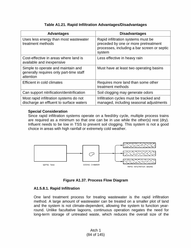
Table A1.21. Rapid Infiltration Advantages/Disadvantages
Advantages Disadvantages Uses less energy than most wastewater treatment methods
Rapid infiltration systems must be preceded by one or more pretreatment processes, including a bar screen or septic system
Cost-effective in areas where land is available and inexpensive
Less effective in heavy rain
Simple to operate and maintain and generally requires only part-time staff attention
Must have at least two operating basins
Efficient in cold climates Requires more land than some other treatment methods
Can support nitrification/denitrification Soil clogging may generate odors Most rapid infiltration systems do not discharge an effluent to surface waters
Infiltration cycles must be tracked and managed, including seasonal adjustments
Special Consideration Since rapid infiltration systems operate on a feed/dry cycle, multiple process trains are required as a minimum so that one can be in use while the other(s) rest (dry). Influent needs to be low in TSS to prevent soil clogging. This system is not a good choice in areas with high rainfall or extremely cold weather.
Figure A1.37. Process Flow Diagram
A1.5.8.1. Rapid Infiltration
One land treatment process for treating wastewater is the rapid infiltration method. A large amount of wastewater can be treated on a smaller plot of land and the system is not climate-dependent, allowing the system to function year-round. Unlike facultative lagoons, continuous operation negates the need for long-term storage of untreated waste, which reduces the overall size of the
Atch 1
(84 of 145)
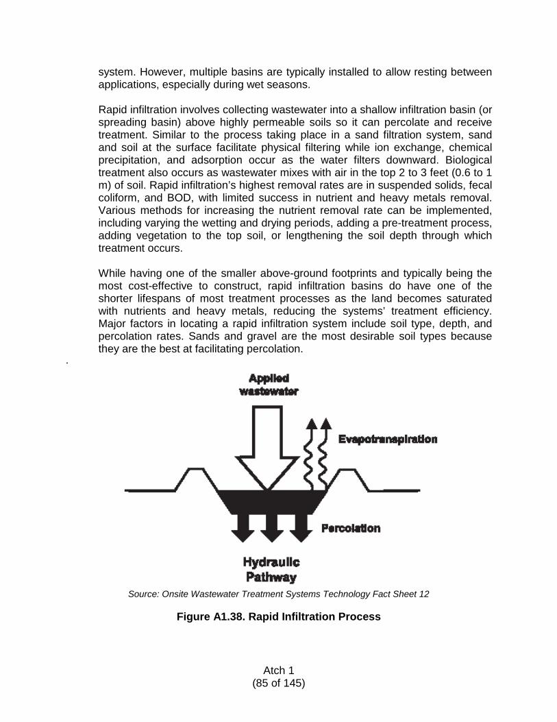
system. However, multiple basins are typically installed to allow resting between applications, especially during wet seasons. Rapid infiltration involves collecting wastewater into a shallow infiltration basin (or spreading basin) above highly permeable soils so it can percolate and receive treatment. Similar to the process taking place in a sand filtration system, sand and soil at the surface facilitate physical filtering while ion exchange, chemical precipitation, and adsorption occur as the water filters downward. Biological treatment also occurs as wastewater mixes with air in the top 2 to 3 feet (0.6 to 1 m) of soil. Rapid infiltration’s highest removal rates are in suspended solids, fecal coliform, and BOD, with limited success in nutrient and heavy metals removal. Various methods for increasing the nutrient removal rate can be implemented, including varying the wetting and drying periods, adding a pre-treatment process, adding vegetation to the top soil, or lengthening the soil depth through which treatment occurs. While having one of the smaller above-ground footprints and typically being the most cost-effective to construct, rapid infiltration basins do have one of the shorter lifespans of most treatment processes as the land becomes saturated with nutrients and heavy metals, reducing the systems’ treatment efficiency. Major factors in locating a rapid infiltration system include soil type, depth, and percolation rates. Sands and gravel are the most desirable soil types because they are the best at facilitating percolation.
.
Source: Onsite Wastewater Treatment Systems Technology Fact Sheet 12
Figure A1.38. Rapid Infiltration Process
Atch 1
(85 of 145)
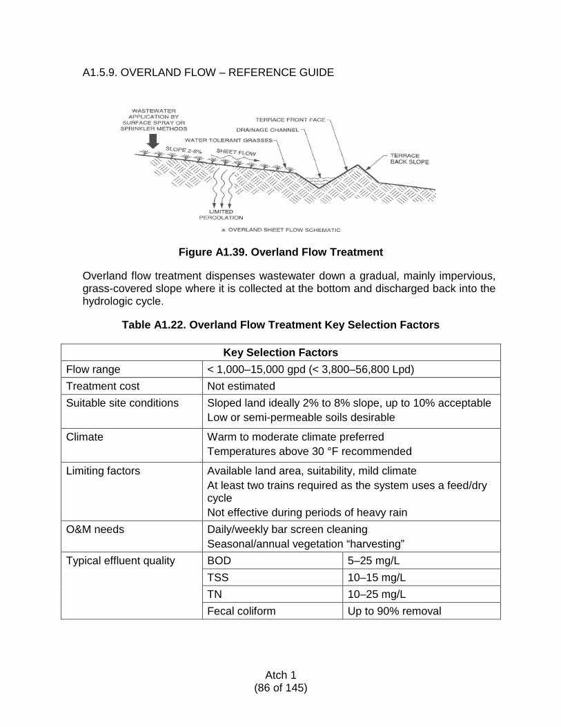
A1.5.9. OVERLAND FLOW – REFERENCE GUIDE
Figure A1.39. Overland Flow Treatment
Overland flow treatment dispenses wastewater down a gradual, mainly impervious, grass-covered slope where it is collected at the bottom and discharged back into the hydrologic cycle.
Table A1.22. Overland Flow Treatment Key Selection Factors
Key Selection Factors
Flow range < 1,000–15,000 gpd (< 3,800–56,800 Lpd) Treatment cost Not estimated Suitable site conditions Sloped land ideally 2% to 8% slope, up to 10% acceptable
Low or semi-permeable soils desirable
Climate Warm to moderate climate preferred Temperatures above 30 °F recommended
Limiting factors Available land area, suitability, mild climate At least two trains required as the system uses a feed/dry cycle Not effective during periods of heavy rain
O&M needs Daily/weekly bar screen cleaning Seasonal/annual vegetation “harvesting”
Typical effluent quality BOD 5–25 mg/L TSS 10–15 mg/L TN 10–25 mg/L Fecal coliform Up to 90% removal
Atch 1
(86 of 145)
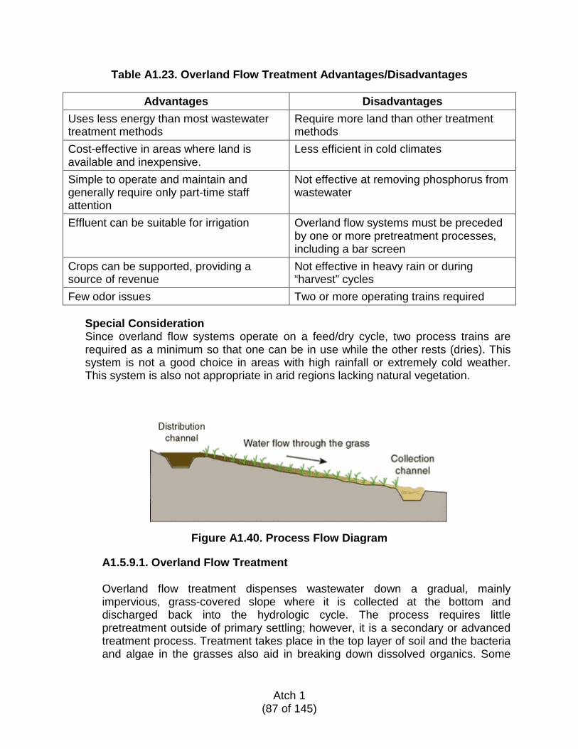
Table A1.23. Overland Flow Treatment Advantages/Disadvantages
Advantages Disadvantages Uses less energy than most wastewater treatment methods
Require more land than other treatment methods
Cost-effective in areas where land is available and inexpensive.
Less efficient in cold climates
Simple to operate and maintain and generally require only part-time staff attention
Not effective at removing phosphorus from wastewater
Effluent can be suitable for irrigation Overland flow systems must be preceded by one or more pretreatment processes, including a bar screen
Crops can be supported, providing a source of revenue
Not effective in heavy rain or during “harvest” cycles
Few odor issues Two or more operating trains required
Special Consideration Since overland flow systems operate on a feed/dry cycle, two process trains are required as a minimum so that one can be in use while the other rests (dries). This system is not a good choice in areas with high rainfall or extremely cold weather. This system is also not appropriate in arid regions lacking natural vegetation.
Figure A1.40. Process Flow Diagram
A1.5.9.1. Overland Flow Treatment
Overland flow treatment dispenses wastewater down a gradual, mainly impervious, grass-covered slope where it is collected at the bottom and discharged back into the hydrologic cycle. The process requires little pretreatment outside of primary settling; however, it is a secondary or advanced treatment process. Treatment takes place in the top layer of soil and the bacteria and algae in the grasses also aid in breaking down dissolved organics. Some
Atch 1
(87 of 145)
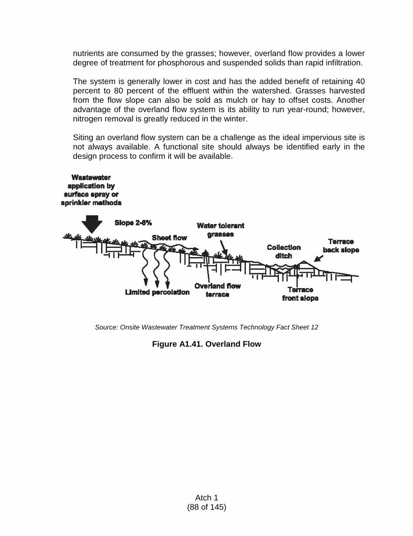
nutrients are consumed by the grasses; however, overland flow provides a lower degree of treatment for phosphorous and suspended solids than rapid infiltration. The system is generally lower in cost and has the added benefit of retaining 40 percent to 80 percent of the effluent within the watershed. Grasses harvested from the flow slope can also be sold as mulch or hay to offset costs. Another advantage of the overland flow system is its ability to run year-round; however, nitrogen removal is greatly reduced in the winter. Siting an overland flow system can be a challenge as the ideal impervious site is not always available. A functional site should always be identified early in the design process to confirm it will be available.
Source: Onsite Wastewater Treatment Systems Technology Fact Sheet 12
Figure A1.41. Overland Flow
Atch 1
(88 of 145)
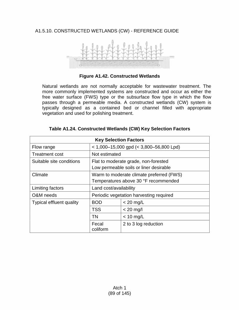
A1.5.10. CONSTRUCTED WETLANDS (CW) - REFERENCE GUIDE
Figure A1.42. Constructed Wetlands Natural wetlands are not normally acceptable for wastewater treatment. The more commonly implemented systems are constructed and occur as either the free water surface (FWS) type or the subsurface flow type in which the flow passes through a permeable media. A constructed wetlands (CW) system is typically designed as a contained bed or channel filled with appropriate vegetation and used for polishing treatment.
Table A1.24. Constructed Wetlands (CW) Key Selection Factors
Key Selection Factors Flow range < 1,000–15,000 gpd (< 3,800–56,800 Lpd) Treatment cost Not estimated Suitable site conditions Flat to moderate grade, non-forested
Low permeable soils or liner desirable Climate Warm to moderate climate preferred (FWS)
Temperatures above 30 °F recommended Limiting factors Land cost/availability O&M needs Periodic vegetation harvesting required Typical effluent quality BOD < 20 mg/L TSS < 20 mg/l TN < 10 mg/L Fecal
coliform 2 to 3 log reduction
Atch 1
(89 of 145)
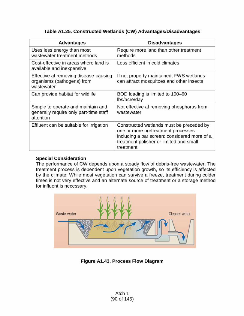
Table A1.25. Constructed Wetlands (CW) Advantages/Disadvantages
Advantages Disadvantages Uses less energy than most wastewater treatment methods
Require more land than other treatment methods
Cost-effective in areas where land is available and inexpensive
Less efficient in cold climates
Effective at removing disease-causing organisms (pathogens) from wastewater
If not property maintained, FWS wetlands can attract mosquitoes and other insects
Can provide habitat for wildlife BOD loading is limited to 100–60 lbs/acre/day
Simple to operate and maintain and generally require only part-time staff attention
Not effective at removing phosphorus from wastewater
Effluent can be suitable for irrigation Constructed wetlands must be preceded by one or more pretreatment processes including a bar screen; considered more of a treatment polisher or limited and small treatment
Special Consideration The performance of CW depends upon a steady flow of debris-free wastewater. The treatment process is dependent upon vegetation growth, so its efficiency is affected by the climate. While most vegetation can survive a freeze, treatment during colder times is not very effective and an alternate source of treatment or a storage method for influent is necessary.
Figure A1.43. Process Flow Diagram
Atch 1
(90 of 145)
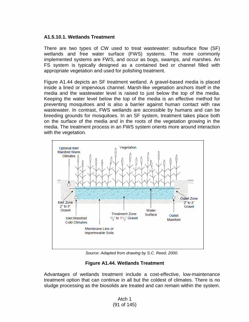
A1.5.10.1. Wetlands Treatment
There are two types of CW used to treat wastewater: subsurface flow (SF) wetlands and free water surface (FWS) systems. The more commonly implemented systems are FWS, and occur as bogs, swamps, and marshes. An FS system is typically designed as a contained bed or channel filled with appropriate vegetation and used for polishing treatment. Figure A1.44 depicts an SF treatment wetland. A gravel-based media is placed inside a lined or impervious channel. Marsh-like vegetation anchors itself in the media and the wastewater level is raised to just below the top of the media. Keeping the water level below the top of the media is an effective method for preventing mosquitoes and is also a barrier against human contact with raw wastewater. In contrast, FWS wetlands are accessible by humans and can be breeding grounds for mosquitoes. In an SF system, treatment takes place both on the surface of the media and in the roots of the vegetation growing in the media. The treatment process in an FWS system orients more around interaction with the vegetation.
Source: Adapted from drawing by S.C. Reed, 2000.
Figure A1.44. Wetlands Treatment
Advantages of wetlands treatment include a cost-effective, low-maintenance treatment option that can continue in all but the coldest of climates. There is no sludge processing as the biosolids are treated and can remain within the system.
Atch 1
(91 of 145)
Unfortunately, CW typically requires large portions of land and over time become saturated with nutrients and other treatment byproducts.
A1.5.11. COMMERCIAL SYSTEMS AND PACKAGE PLANT – REFERENCE GUIDE
There are several types of commercially available package plants. Figure A1.45 illustrates an extended aeration plant. The data in Table A1.26 and Table A1.27 are generic to all package plants. All package plant influents must be screened and a reliable source of power is required to run the rotating equipment (pumps, blowers).
Table A1.26. Commercial Systems and Package Plant Key Selection Factors
Key Selection Factors
Flow range 3,000–15,000 gpd (11,350–56,800 Lpd) Treatment cost range $150–$200 per gallon based on CONUS installation Suitable site conditions Available land should support a constructed system
Discharge can be to a leaching field or surface waters Climate Will function in any climate except extreme Arctic
conditions Limiting factors Cost, licensed operator availability, and suitability O&M Needs Inspect process tanks and equipment weekly
Check and adjust timer and controls quarterly Check pump weekly and distribution system quarterly Refer to manufacturer’s O&M manual regularly
Typical effluent quality BOD 30 mg/L or less TSS 30 mg/L or less TN < 25 mg/L (with disinfection) Fecal coliform < 2 to 12.5 MPN/100mL
Atch 1
(92 of 145)
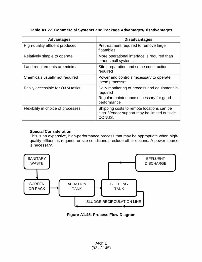
Table A1.27. Commercial Systems and Package Advantages/Disadvantages
Advantages Disadvantages
High-quality effluent produced Pretreatment required to remove large floatables
Relatively simple to operate More operational interface is required than other small systems
Land requirements are minimal Site preparation and some construction required
Chemicals usually not required Power and controls necessary to operate these processes
Easily accessible for O&M tasks Daily monitoring of process and equipment is required Regular maintenance necessary for good performance
Flexibility in choice of processes Shipping costs to remote locations can be high. Vendor support may be limited outside CONUS.
Special Consideration This is an expensive, high-performance process that may be appropriate when high-quality effluent is required or site conditions preclude other options. A power source is necessary.
Figure A1.45. Process Flow Diagram
SLUDGE RECIRCULATION LINE
SANITARY WASTE
SCREEN OR RACK
AERATION TANK
SETTLING TANK
EFFLUENT DISCHARGE
Atch 1
(93 of 145)
A1.5.12. COMMERCIAL PROCESS SYSTEMS AVAILABLE
For onsite wastewater management requiring advanced treatment beyond the conventional septic tank and leaching field, many systems have been developed as alternatives to the RSF design, considered the generic advanced treatment design. The popularity of these commercial systems is due to the fact that for the same design flow the process tanks typically require a smaller footprint than the RSF design and the tanks can be installed below grade, which can be advantageous when space is at a premium. Please note that legal, operational, or practical factors might limit selection of commercial system alternatives. These systems incorporate the advances made in municipal processes and apply them to a smaller-scale system. While most are simple adaptations, many include proprietary features and are trade name-protected. The following are some of the available commercial systems capable of meeting a discharge effluent limit of 30 mg/L TSS, 30 mg/L BOD, 25 mg/L total nitrogen. Some reliably provide nitrogen reduction to below 10 mg/L where necessary, but often require soda ash for alkalinity adjustment and a carbon source for the denitrification conversion necessary to reach that low value. Fecal coliform removals can also be achieved with disinfection.
• Packed Bed Filter System
Packed bed filter systems are similar to RSF. However, rather than sand, the system utilizes a lightweight textile media with a large surface area. The system can provide equivalent treatment to that of a sand filter loaded at rates of 25 to 50 gpd/ft2 (1,020 to 2,040 Lpd/m2). After flowing into the processing tank, sewage separates into scum, sludge, and liquid effluent. The effluent flows into the filter media pod where microorganisms growing on the synthetic textile sheets remove impurities. After passing through the tank and the packed bed filter, the effluent is discharged to the leaching field for further treatment prior to groundwater integration.
• Biological Nutrient Removal (BNR)
Some BNR systems utilize a submerged attached growth bioreactor that operates in batch mode. This type of unit has a deep bed sand filter designed for the removal of soluble organic matter, nitrogen, and suspended solids within a single reactor. In addition to the deep bed sand filters, the system also contains an anoxic/equalization tank that serves as a primary clarifier ahead of the bioreactor. This bioreactor is mixed but not aerated to encourage denitrification of the recycled flows from the reactor. Within the reactor the sand media functions as a filter and provides the surface area for maintaining the attached growth biomass. Recycle pumps and air compressors are used to maintain desired aerobic and anoxic process conditions at various batch stages.
Atch 1
(94 of 145)
• Aerobic Nitrogen Reduction
Aerobic nitrogen reduction systems use the natural settling process that takes place before the wastewater moves into the activated sludge treatment module. Oxygen is introduced to facilitate mixing through the media channel. After being cleansed by the microbes in the media channel, effluent is typically discharged to a leaching field for groundwater disposal.
• Biofilter Systems
The biofilter system includes a synthetic, absorbent filter medium configured as a free-draining, attached-growth, biological trickling filter. The engineered filter medium creates an environment that encourages microbial attachment that simultaneously provides aerobic, anaerobic, and anoxic environments for biological treatment, without air compressors and their high energy use. Biofilters have performed well in Canada and are appropriate for cold regions. This effluent is typically discharged to a leaching field for groundwater disposal.
• Membrane Biological Reactor (MBR) Systems
Recent technical innovation and significant membrane cost reductions have pushed MBRs to become an established process option to treat wastewater. The MBR process is also capable of enhanced wastewater treatment where effluent reuse may be a goal. The MBR process consists of a suspended growth biological reactor integrated with an ultrafiltration membrane system, using hollow fiber membranes. Essentially, the ultrafiltration system replaces the solids-separation function of secondary clarifiers and sand filters in a conventional activated sludge system, producing a high-quality effluent, simplifying operation, and greatly reducing space requirements.
• Extended Aeration
Extended aeration includes the following components: bar screen, aeration chamber, clarifier chamber, and recycling. The effluent can be disinfected and capable of meeting reuse quality. The extended aeration or aerobic bioreactor system is not a proprietary process; however, many manufacturers trademark their package system.
A1.5.12.1. System Selection and Purchase Guide
As noted, there are several alternatives available for consideration. Specifications should be prepared by AFCEC or its consultant for selecting materials and equipment for construction of each system as appropriate. Many systems can be delivered as a single package for installation with limited pre-
Atch 1
(95 of 145)
construction; however, site preparation, including a leveling pad or foundation, is a minimum requirement. Guidelines for system installation and testing are also provided by the manufacturer or supplier. Specialty treatment equipment should be ordered with all O&M manuals, including troubleshooting guides. Commercial treatment systems are typically proprietary systems purchased from a single supplier and delivered as a unit, which may require some assembly and site preparation prior to delivery. These systems are often called “package plants.” There is no common requirement for operating a proprietary system as each supplier has their own unique requirements. Commercial treatment systems come in several process types; some are designed to achieve advanced treatment for surface water discharge, whereas other systems are intended as an add-on to a conventional septic system intended for subsurface discharge of the final effluent. When working with consultants or designers, consider that these professionals are most comfortable with technologies they are already familiar with. For this reason, it is useful to get more than one estimate or opinion with written justification why their recommendations are the most appropriate for the site and your needs. Each system type has its own merits. Evaluating different methods and manufacturers can be a daunting task even for experienced system designers. Selecting a package plant for use at a semi-permanent deployment location would likely be considered when the site is not well-suited for more conventional treatment methods like septic systems or lagoons or if advanced treatment is required due to local conditions or regulations. The person charged with the task of selecting a technology and its fabricator needs to consider several factors, including, but not limited to:
• Discharge quality requirements • Site-related issues • Constructability • Purchase cost, including shipping • Installation costs • O&M costs • O&M frequency and staffing requirements • Power requirements and availability • Availability of operating supplies (e.g., lubricants, chemicals)
The following checklists provide an outline of the parameters that should be taken into consideration prior to selecting a package plant and vendor.
A1.5.12.2. Process Factors to Consider
WWTF process is appropriate for wastewater flows and generated loads WWTF effluent quality will meet established standards Ease of installation and future repairs Ease of operation
Atch 1
(96 of 145)
Maintenance requirements and frequency Component lifecycle Are special lubricants or chemicals required? Are they locally available? Constructability: Are suitable contractors locally available? Will the WWTF be affected by climate conditions?
A1.5.12.3. Site Considerations
Consider the available area and location within the deployment site Proximity to drinking water wells Proximity to surface water and wetlands Investigate permitting requirements Adequate space to facilitate installation and repairs? Ease of access for service, delivery, and maintenance vehicles? Existing obstacles: Boulders, structures, wildlife migration route? Drainage pattern Ease of any required excavation Potential for flooding Snow-removal issues, if applicable Potential facility appearance issues if there are concerned site abutters
A1.5.12.4. Cost Considerations
Design fees by engineering consultant, including detailed site plan and
performance specifications for a complete system Purchase cost of the complete WWTF that meets the required permits and
warranties specified Shipping and delivery cost of the WWTF and all required materials and
equipment. Installation costs, including equipment and personnel. Equipment supplier
may provide separate contract for installation, start-up, and training of local operator.
O&M costs, including chemical and materials, labor, special personnel, and sludge disposal
Monitoring costs; lab facilities required for testing
It is important to consider that while some technologies may have a lower initial capital cost they may also have a high O&M cost. Cost estimates should also include electricity and the cost of spare parts over the lifecycle of the facility. See Table A1.28 for a sample lifecycle comparison evaluation.
Atch 1
(97 of 145)
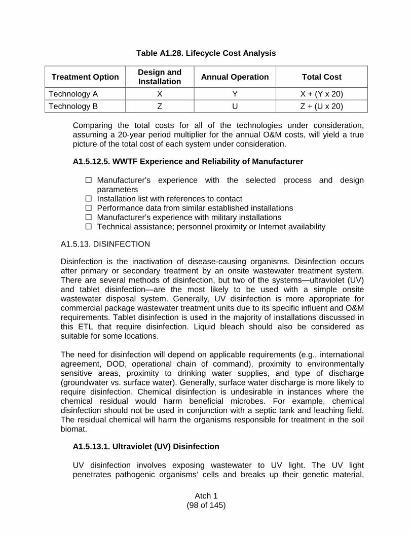
Table A1.28. Lifecycle Cost Analysis
Treatment Option Design and Installation Annual Operation Total Cost
Technology A X Y X + (Y x 20) Technology B Z U Z + (U x 20)
Comparing the total costs for all of the technologies under consideration, assuming a 20-year period multiplier for the annual O&M costs, will yield a true picture of the total cost of each system under consideration.
A1.5.12.5. WWTF Experience and Reliability of Manufacturer
Manufacturer’s experience with the selected process and design
parameters Installation list with references to contact Performance data from similar established installations Manufacturer’s experience with military installations Technical assistance; personnel proximity or Internet availability
A1.5.13. DISINFECTION
Disinfection is the inactivation of disease-causing organisms. Disinfection occurs after primary or secondary treatment by an onsite wastewater treatment system. There are several methods of disinfection, but two of the systems—ultraviolet (UV) and tablet disinfection—are the most likely to be used with a simple onsite wastewater disposal system. Generally, UV disinfection is more appropriate for commercial package wastewater treatment units due to its specific influent and O&M requirements. Tablet disinfection is used in the majority of installations discussed in this ETL that require disinfection. Liquid bleach should also be considered as suitable for some locations. The need for disinfection will depend on applicable requirements (e.g., international agreement, DOD, operational chain of command), proximity to environmentally sensitive areas, proximity to drinking water supplies, and type of discharge (groundwater vs. surface water). Generally, surface water discharge is more likely to require disinfection. Chemical disinfection is undesirable in instances where the chemical residual would harm beneficial microbes. For example, chemical disinfection should not be used in conjunction with a septic tank and leaching field. The residual chemical will harm the organisms responsible for treatment in the soil biomat.
A1.5.13.1. Ultraviolet (UV) Disinfection
UV disinfection involves exposing wastewater to UV light. The UV light penetrates pathogenic organisms’ cells and breaks up their genetic material,
Atch 1
(98 of 145)
making it impossible for them to reproduce or sustain life. Generally, this form of disinfection will only be used with commercial package systems specifically designed for UV disinfection.
UV disinfection has several advantages, including the following:
• No danger of overdosing • No smell • Short contact time • Does not require storage of hazardous material • Minimal space requirements • Relatively insensitive to temperature and pH fluctuations • Will not cause any byproducts or residuals to be discharged to the
environment.
However, UV disinfection has some disadvantages, including: • Higher energy requirements compared to chemical disinfection • Cannot be used when wastewater has high levels of suspended solids,
turbidity, color, or soluble organics • Replacement parts may not be available in remote locations • Requires a higher level of design precision • Requires a relatively high level of operator skill
The following design considerations for UV systems should be noted:
• A stable source of high-voltage electricity will be required. • The lamps may not run without wastewater flow; this will cause
overheating • A set of spare parts recommended by the manufacturer should be stored
on site so the system will not be inoperable due to shipping delays. • The UV lamps should be equipped with an automatic cleaning system,
such as wipers, to remove buildup on the lamp; generally, the UV disinfection system manufacturer will provide such an automatic cleaning system.
• A monitoring and alarm (instrumentation and control) system should be provided by the manufacturer.
• Unless instantaneous backup power is available, the effluent should be stored during power outages.
• Providing two units assures continuous disinfection even when one unit is inoperable.
• In all cases consult the manufacturer for project-specific site requirements and equipment selection.
O&M requirements include:
• Regular inspection and maintenance as recommended by the manufacturer
Atch 1
(99 of 145)
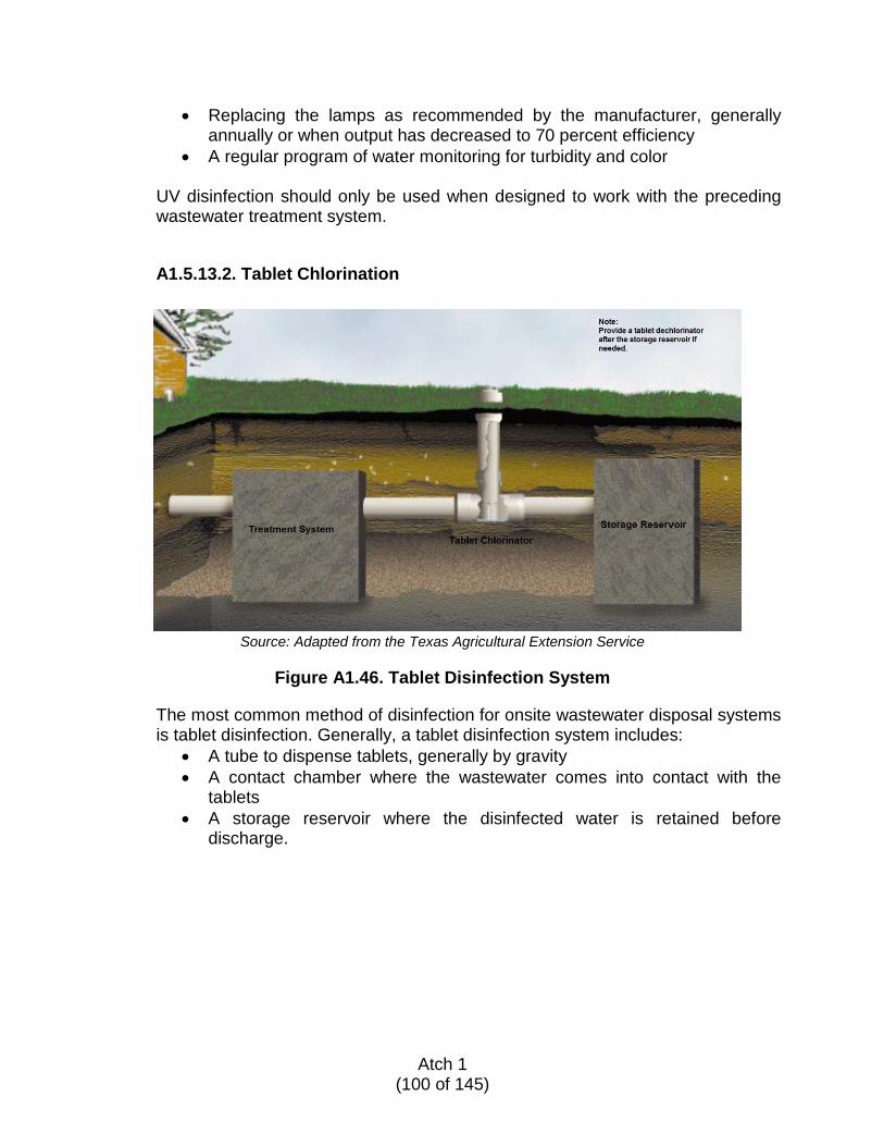
• Replacing the lamps as recommended by the manufacturer, generally annually or when output has decreased to 70 percent efficiency
• A regular program of water monitoring for turbidity and color
UV disinfection should only be used when designed to work with the preceding wastewater treatment system.
A1.5.13.2. Tablet Chlorination
Source: Adapted from the Texas Agricultural Extension Service
Figure A1.46. Tablet Disinfection System
The most common method of disinfection for onsite wastewater disposal systems is tablet disinfection. Generally, a tablet disinfection system includes:
• A tube to dispense tablets, generally by gravity • A contact chamber where the wastewater comes into contact with the
tablets • A storage reservoir where the disinfected water is retained before
discharge.
Atch 1
(100 of 145)
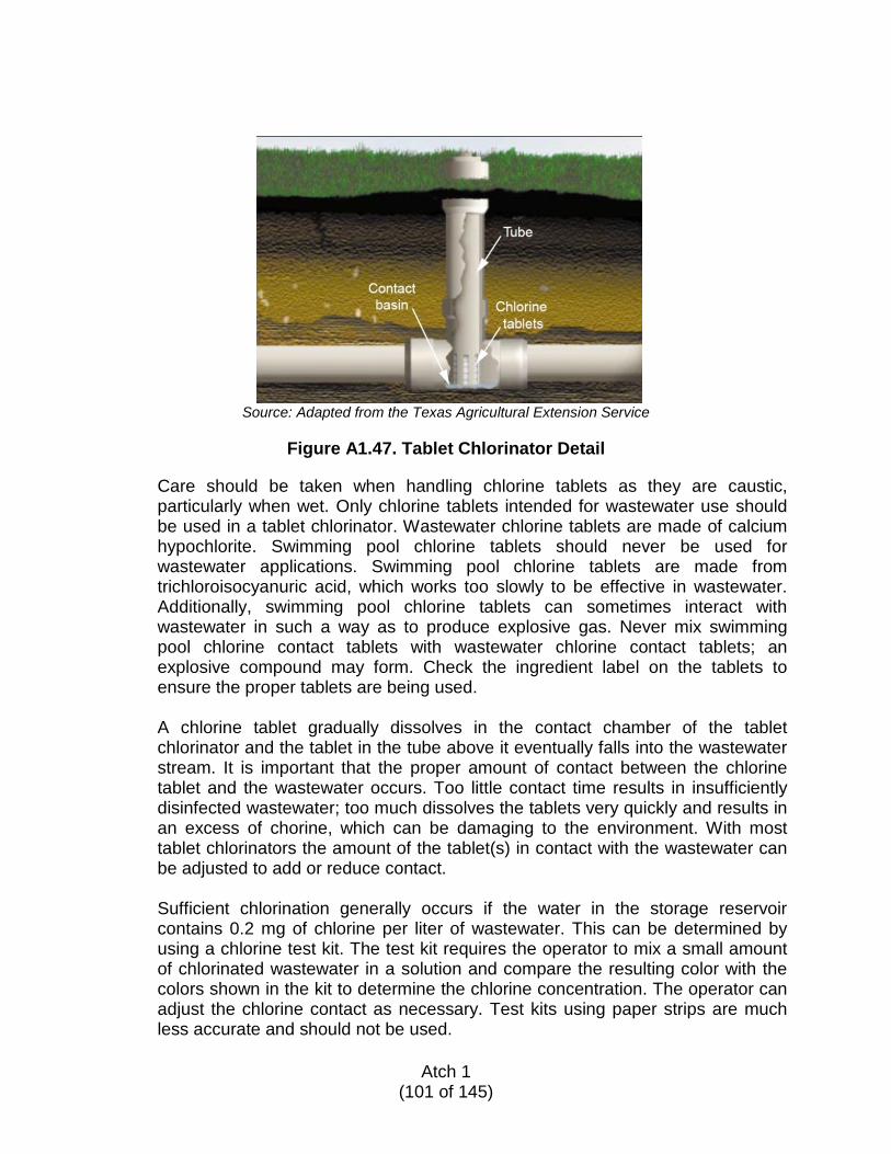
Source: Adapted from the Texas Agricultural Extension Service
Figure A1.47. Tablet Chlorinator Detail
Care should be taken when handling chlorine tablets as they are caustic, particularly when wet. Only chlorine tablets intended for wastewater use should be used in a tablet chlorinator. Wastewater chlorine tablets are made of calcium hypochlorite. Swimming pool chlorine tablets should never be used for wastewater applications. Swimming pool chlorine tablets are made from trichloroisocyanuric acid, which works too slowly to be effective in wastewater. Additionally, swimming pool chlorine tablets can sometimes interact with wastewater in such a way as to produce explosive gas. Never mix swimming pool chlorine contact tablets with wastewater chlorine contact tablets; an explosive compound may form. Check the ingredient label on the tablets to ensure the proper tablets are being used.
A chlorine tablet gradually dissolves in the contact chamber of the tablet chlorinator and the tablet in the tube above it eventually falls into the wastewater stream. It is important that the proper amount of contact between the chlorine tablet and the wastewater occurs. Too little contact time results in insufficiently disinfected wastewater; too much dissolves the tablets very quickly and results in an excess of chorine, which can be damaging to the environment. With most tablet chlorinators the amount of the tablet(s) in contact with the wastewater can be adjusted to add or reduce contact. Sufficient chlorination generally occurs if the water in the storage reservoir contains 0.2 mg of chlorine per liter of wastewater. This can be determined by using a chlorine test kit. The test kit requires the operator to mix a small amount of chlorinated wastewater in a solution and compare the resulting color with the colors shown in the kit to determine the chlorine concentration. The operator can adjust the chlorine contact as necessary. Test kits using paper strips are much less accurate and should not be used.
Atch 1
(101 of 145)
Approximately 15 minutes of contact time with the 0.2 mg/L chlorine solution is required in the storage reservoir prior to discharge for proper disinfection. An example calculation to size the storage reservoir follows.
Known: Average daily flow: 3,000 gpd Peak flow (peaking factor): 2.5 x average flow rate Detention time: 15 minutes
Determine: Volume of storage reservoir
Calculation: Average flow rate: 3,000 gpd ÷ 1,440 minutes per day = 2.1 gpm Peak flow: 2.5 x 2 gpm = 5.2 gpm Volume = flow x detention time = 5.2 gpm x 15 minutes = 78 gallons
The following O&M is required for a tablet chlorinator:
• Use only wastewater-approved chlorine contact tablets • Inspect at least two times per week to ensure the chlorinator contains
tablets at all times • Tablets can become blocked in the tube; check for and remove blockages
during inspection • Do not add more than two to five tablets at a time to reduce the risk of
blockages • Use a chlorine test kit to determine the chlorine concentration in the
storage reservoir; insufficient chlorine or septic odors indicate a blockage or insufficient chlorine contact
Because chlorine is toxic to aquatic life, dechlorination after the storage reservoir may be required, particularly if the discharge is to a surface water body. Most chlorine tablet manufacturers also sell sodium sulfite (Na2SO3) tablets to dechlorinate. The sodium sulfite tablets are placed in a contact chamber similar to the chlorine contact chamber but downstream of the storage reservoir. The reaction between the chlorine and the sodium sulfite is instantaneous so another storage reservoir is not required. About 2 mg/L of sodium sulfite is required per 1 mg/L of chlorine.
A1.5.13.3. Disinfection with Liquid Bleach
Disinfection with liquid bleach can range from sophisticated installations using metering pumps to simple, manual addition of the chemical. Where metering pumps are used, the pump should be designed to withstand the corrosive effect of liquid bleach. Additionally, the pump should be adjusted to meter the appropriate amount of the chemical based on flow; this may require flow meters
Atch 1
(102 of 145)

with instrumentation and a control system. The system should be designed by a registered professional engineer. Manual bleach addition should occur only when no other resource is available. The operator may pour bleach into a wetwell of wastewater and allow mixing and contact time. Generally, 15 minutes of contact with 0.2 mg/L of bleach is adequate for disinfection. The operator should determine the concentration of liquid bleach for the volume of liquid; the appropriate amount can then be metered out to achieve disinfection. Care should be taken when handling liquid bleach—it is corrosive and damaging to the skin and eyes. Additionally, its vapors are corrosive to metals; metal objects generally should not be stored in the same room as liquid bleach. A liquid bleach storage area should be well-ventilated. Since liquid bleach is more complex and volatile, it is recommended that tablet chlorination/dechlorination should always be used, with very few exceptions.
A1.6. COST COMPARISON OF ALTERNATIVES Intended for planning and comparison only, cost estimates are provided in Table A1.29 for selected onsite treatment systems. Each WWTF estimate is based on a system sized for 3,000 gpd (11.360 Lpd) of wastewater flow serving a site population of 75. This assumes typical wastewater characteristics for flows generated at approximately 40 gpcd (151 Lpcd). These cost estimates are based on systems installed in CONUS. The May 2012 Engineering News-Record (ENR) Construction Cost Index of 9289.65 is based on a 20-city average for CONUS and is used only for estimating relative adjustments for planning level construction cost estimates in future years. Refer to http://enr.construction.com/economics/ for additional information on using this index. The costs presented in Table A1.29 are based on a CONUS installation utilizing local materials and equipment for a 3,000-gpd (11,360 Lpd) -system to be consistent with the representative design and installation guides provided herein. Refer to the specific ETL paragraph as noted for details on the sizing and installation requirements.
Atch 1
(103 of 145)
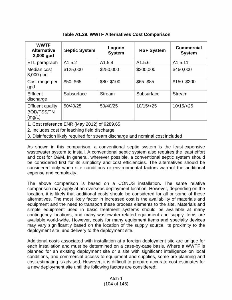
Table A1.29. WWTF Alternatives Cost Comparison
WWTF
Alternative 3,000 gpd
Septic System Lagoon System RSF System Commercial
System
ETL paragraph A1.5.2 A1.5.4 A1.5.6 A1.5.11 Median cost 3,000 gpd
$125,000 $250,000 $200,000 $450,000
Cost range per gpd
$50–$65 $80–$100 $65–$85 $150–$200
Effluent discharge
Subsurface Stream Subsurface Stream
Effluent quality BOD/TSS/TN (mg/L)
50/40/25 50/40/25 10/15/<25 10/15/<25
1. Cost reference ENR (May 2012) of 9289.65 2. Includes cost for leaching field discharge 3. Disinfection likely required for stream discharge and nominal cost included As shown in this comparison, a conventional septic system is the least-expensive wastewater system to install. A conventional septic system also requires the least effort and cost for O&M. In general, wherever possible, a conventional septic system should be considered first for its simplicity and cost efficiencies. The alternatives should be considered only when site conditions or environmental factors warrant the additional expense and complexity. The above comparison is based on a CONUS installation. The same relative comparison may apply at an overseas deployment location. However, depending on the location, it is likely that additional costs should be considered for all or some of these alternatives. The most likely factor in increased cost is the availability of materials and equipment and the need to transport these process elements to the site. Materials and simple equipment used in basic treatment systems should be available at many contingency locations, and many wastewater-related equipment and supply items are available world-wide. However, costs for many equipment items and specialty devices may vary significantly based on the location of the supply source, its proximity to the deployment site, and delivery to the deployment site. Additional costs associated with installation at a foreign deployment site are unique for each installation and must be determined on a case-by-case basis. Where a WWTF is planned for an existing deployment site or a site with significant intelligence on local conditions, and commercial access to equipment and supplies, some pre-planning and cost-estimating is advised. However, it is difficult to prepare accurate cost estimates for a new deployment site until the following factors are considered:
Atch 1
(104 of 145)
Availability and purchase cost of materials and process equipment
• Does the location have access to piping and concrete suppliers? • Can the site provide adequate materials for back-fill and grading?
Delivered cost of materials and equipment to the deployment site
• Is delivery limited to air shipment? • Is weight and size of process equipment a limiting factor?
Site preparation and utility requirements
• Is power required for pumping or process equipment? • Is water required for O&M of process equipment?
Installation costs, including labor and equipment
• Is construction equipment available at the site? • Can a local contractor be hired for installation?
Expertise required for installation and start-up
• Lower-complexity WWTF requires minimal expertise—likely satisfied by Air Force personnel
• Commercial systems will require professional assistance—additional cost for services
Available personnel/operator qualified for WWTF O&M (for remote locations with
commercial systems an onsite operator is recommended) • Commercial systems will require onsite qualified licensed operator • On-line or web-based assistance may be available to the operator for
additional troubleshooting • On-line monitoring connection by a supplier is not likely available to military
deployment sites A1.7. WASTEWATER COLLECTION SYSTEMS AND PUMPING The type of collection system will depend mainly on site topography, process selection, and siting of the treatment system and outlet/discharge relative to the source location. Where possible, gravity piping is encouraged since pumping requires electrical power for operation and controls. Legal (e.g., international agreements) and operational (e.g., COCOM or operational chain of command) requirements may also affect the type of collection system that can be used at a specific location.
A1.7.1. GRAVITY SEWERS
PVC sewer pipe, couplings, and fittings should conform to ASTM D3034, Standard Specification for Type PSM Poly(Vinyl Chloride) (PVC) Sewer Pipe and Fittings, with standard dimension ratio (SDR) 35. Joints are typically push-on, using permanently bonded elastomeric ring gaskets per the pipe manufacturer’s written instructions.
Atch 1
(105 of 145)
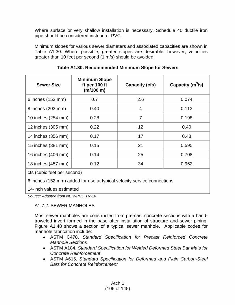
Where surface or very shallow installation is necessary, Schedule 40 ductile iron pipe should be considered instead of PVC. Minimum slopes for various sewer diameters and associated capacities are shown in Table A1.30. Where possible, greater slopes are desirable; however, velocities greater than 10 feet per second (1 m/s) should be avoided.
Table A1.30. Recommended Minimum Slope for Sewers
Sewer Size Minimum Slope
ft per 100 ft (m/100 m)
Capacity (cfs) Capacity (m3/s)
6 inches (152 mm) 0.7 2.6 0.074
8 inches (203 mm) 0.40 4 0.113
10 inches (254 mm) 0.28 7 0.198
12 inches (305 mm) 0.22 12 0.40
14 inches (356 mm) 0.17 17 0.48
15 inches (381 mm) 0.15 21 0.595
16 inches (406 mm) 0.14 25 0.708
18 inches (457 mm) 0.12 34 0.962
cfs (cubic feet per second)
6 inches (152 mm) added for use at typical velocity service connections
14-inch values estimated Source: Adapted from NEIWPCC TR-16
A1.7.2. SEWER MANHOLES
Most sewer manholes are constructed from pre-cast concrete sections with a hand-troweled invert formed in the base after installation of structure and sewer piping. Figure A1.48 shows a section of a typical sewer manhole. Applicable codes for manhole fabrication include:
• ASTM C478, Standard Specification for Precast Reinforced Concrete Manhole Sections
• ASTM A184, Standard Specification for Welded Deformed Steel Bar Mats for Concrete Reinforcement
• ASTM A615, Standard Specification for Deformed and Plain Carbon-Steel Bars for Concrete Reinforcement
Atch 1
(106 of 145)
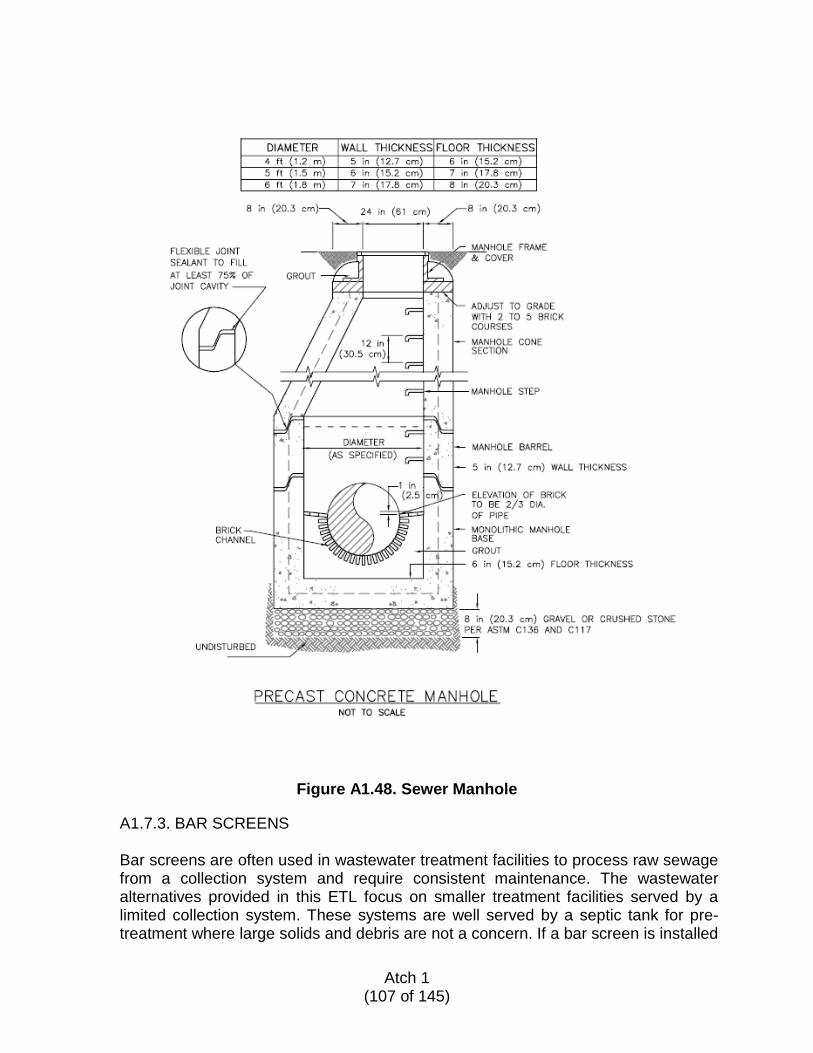
Figure A1.48. Sewer Manhole
A1.7.3. BAR SCREENS
Bar screens are often used in wastewater treatment facilities to process raw sewage from a collection system and require consistent maintenance. The wastewater alternatives provided in this ETL focus on smaller treatment facilities served by a limited collection system. These systems are well served by a septic tank for pre-treatment where large solids and debris are not a concern. If a bar screen is installed
Atch 1
(107 of 145)
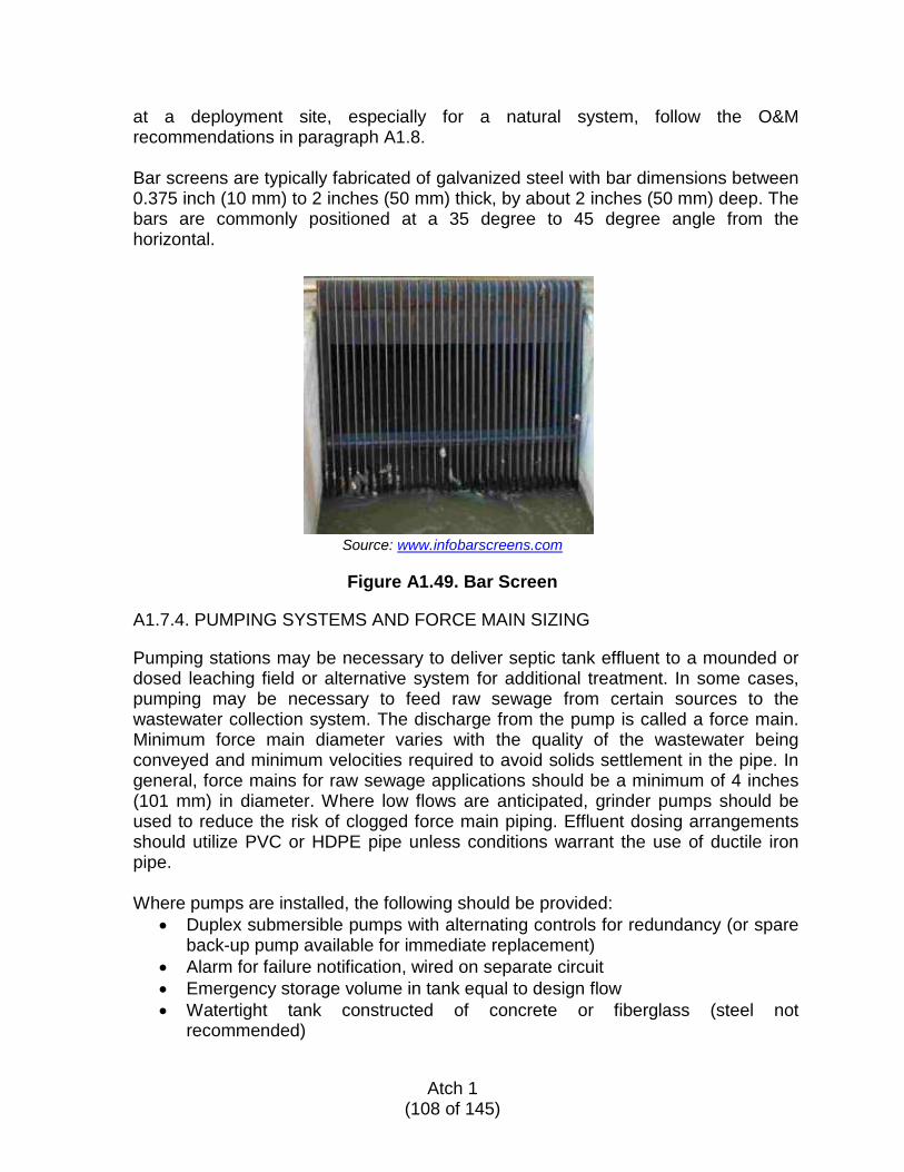
at a deployment site, especially for a natural system, follow the O&M recommendations in paragraph A1.8. Bar screens are typically fabricated of galvanized steel with bar dimensions between 0.375 inch (10 mm) to 2 inches (50 mm) thick, by about 2 inches (50 mm) deep. The bars are commonly positioned at a 35 degree to 45 degree angle from the horizontal.
Source: www.infobarscreens.com
Figure A1.49. Bar Screen
A1.7.4. PUMPING SYSTEMS AND FORCE MAIN SIZING
Pumping stations may be necessary to deliver septic tank effluent to a mounded or dosed leaching field or alternative system for additional treatment. In some cases, pumping may be necessary to feed raw sewage from certain sources to the wastewater collection system. The discharge from the pump is called a force main. Minimum force main diameter varies with the quality of the wastewater being conveyed and minimum velocities required to avoid solids settlement in the pipe. In general, force mains for raw sewage applications should be a minimum of 4 inches (101 mm) in diameter. Where low flows are anticipated, grinder pumps should be used to reduce the risk of clogged force main piping. Effluent dosing arrangements should utilize PVC or HDPE pipe unless conditions warrant the use of ductile iron pipe.
Where pumps are installed, the following should be provided:
• Duplex submersible pumps with alternating controls for redundancy (or spare back-up pump available for immediate replacement)
• Alarm for failure notification, wired on separate circuit • Emergency storage volume in tank equal to design flow • Watertight tank constructed of concrete or fiberglass (steel not
recommended)
Atch 1
(108 of 145)
• Raw sewage flows should be pumped using non-clog or grinder pumps capable of handling 3-inch (76 mm) solids
• Install pumps with a quick-disconnect coupling to facilitate O&M
A1.7.4.1. Pump Selection Procedure and Example
There are several types of pumps available for conveying wastewater. However, the type of pump used in septic tanks and as recirculation pumps for the RSFs are submersible. A submersible pump has a pump and motor designed to be installed in the wet well and may be fully submerged. These pumps do not require an influent pipe but must be submerged for adequate cooling and safe operation. To determine the size of the pump for each application, the required flow, force main size, and total dynamic head (TDH) need to be determined. Once this information has been established, it can be provided to pump manufacturers for pump selection.
Step 1: Determine the Peak Flow
Pumps are sized based on the peak hour flow (peak flow), not the ADF used to size the septic tank, leaching basin, and RSF. Peak flow is determined by multiplying the ADF by a peaking factor (PF). The maximum anticipated flow rate for an installation based on this ETL is 15,000 gpd, which is considered a very low flow. A PF of 5 is recommended for most applications in this flow range.
Peak flow = ADF x PF ADF = 3,000 gpd; PF = 5 Peak flow = 3,000 gpd x 5 Peak flow = 15,000 gpd or 10.5 gpm
Step 2: Determine Required Wet Well Size
Based on the peak flow and the dimensions of the wet well, determine the pump run time per cycle. The following criteria should be used when determining if a wet well is adequately sized:
• Pumps should cycle on/off no more than four times per hour • Pumps should run for several minutes at a time without dewatering
the wet well
Determine volume of wet well per inch
From paragraph A1.5.2, “Conventional Septic Systems”:
L1 = 6 feet
Atch 1 (109 of 145)
W = 6 feet H = 12 feet Volume = 3,000 gallons
Gallons per inch (gpi) = 3,000 gallons ÷ 144 inches gpi = 20.8
Set level control for pumps to turn on 6 inches above low-level set point. Volume to be pumped = 6 inches x 20.8 gpi Volume to be pumped = 125 gallons
Determine pump run time (TP)
TP = 125 gallons ÷ 10.5 gpm TP = 12 minutes
Pump will run one to two times per hour (acceptable)
Step 3: Determine Force Main Size
Once the peak flow has been determined, it is time to size the force main. The diameter of the force main will impact pump selection as the friction losses through the pipe are directly related to the flow rate through the pipe. As a rule of thumb, the velocity of the flow in the force main should be maintained between 3 feet per second (fps) and 5 fps to keep solids suspended and avoid deposition in the line.
Q (cfs) = A (ft2) x V (ft/s)
Rearrange the equation to solve for area (A).
A = Q ÷ V
Convert Q from gpd to cfs:
Q = 15,000 gpd ÷ 7.48 gallons/ft3 ÷ 86,400 seconds/day Q = 0.0232 cfs
Assume velocity = 4 fps
Atch 1
(110 of 145)
Solve for A: A = 0.0232 cfs ÷ 4 fps
A = 0.0058 ft
A = π x r2
Solve for r: r = (A ÷ π)1/2
r = 0.043 feet
r = 0.515 inch
d = 1.03 inches
Use a force main diameter of 1 inch.
Step 4: Determine the TDH
The TDH is the total equivalent height that a fluid is to be pumped, taking into account friction losses in the pipe. TDH is found by adding the difference in water surface elevation (static head) to the losses in the pipe due to friction (fL).
The following is an example for determining the TDH of a septic system pump that pumps to a gravity leaching field.
Step 4a: Calculate Static Head
Pump on elevation: Elevation of influent pipe at leaching field:
Static head (ft) = elevation at leaching field (ft) – pump on elevation (ft)
Static head = 17.43 ft – 7.41 ft Static head = 10.02 ft
Step 4b: Calculate Friction Losses
In addition to the elevation difference between the starting and ending points, the pump also has to overcome the friction of the fluid moving through the pipe. The longer the pipe length between the pump and the final discharge point, the greater the friction loss.
Atch 1
(111 of 145)
Calculate the losses in the straight pipe using the Hazen-Williams Equation
fL = ([4.52 x L X Q1.85) ÷ (C1.85 x d4.87]) x 2.31
Where:
fL = friction loss in feet L = length of pipe (ft) Q = flow C = Hazen-Williams roughness coefficient d = hydraulic diameter (interior diameter of pipe in inches)
If the septic tank effluent to the leaching field includes 400 feet of 1-inch PVC pipe, then the friction loss in the straight pipe can be determined.
Total pipe length = distance from septic tank to leaching field + vertical distance from pump discharge
Total pipe length (ft) = 400 ft + 7.86 ft Total pipe length (ft) = 407.86 ft
Calculate the friction loss in the straight pipe:
fL (ft) = (4.73 x L x Q1.85) ÷ (C1.85 x d4.87)
fL = ([4.73 x 407.86 x (15,000 gpd ÷ 1440 mins/day)1.85] ÷ [1201.85 x 14.87]) x 2.31 fL = 48.48 ft
Additional losses, such as those through fittings, may be considered insignificant and ignored if there are a small number of fittings (less than five). If you have a large number of fittings then the losses should be accounted for by adding another 2 to 3 feet of head loss to the final calculation. If the designer prefers to calculate the actual head loss through these fittings then the designer should consult one of the numerous hydraulic handbooks on the market. These handbooks provide tables, charts, and equations for determining the head loss through fittings.
Step 4c: Determine TDH
TDH = static head + friction losses
Atch 1
(112 of 145)
TDH = 10.02 ft + 48.48 ft = 58.50 ft
Step 4d: Pump Selection
Once the flow rate, force main diameter, and TDH have been determined, contact the pump manufacturer to determine the appropriate pump. Information to provide to pump manufacturer:
• Location of job • Job name • Purchase order number (if applicable) • Pump type (submersible) • Peak flow rate (10.5 gpm) • TDH (59 ft) • Force main diameter (1 inch)
A1.8. OPERATION AND MAINTENANCE OF WASTEWATER TREATMENT SYSTEMS The design capabilities of WWTFs can be effectively utilized only if personnel provide the required attention and maintenance. Good operating techniques provide, as a minimum, the following returns to the installation:
• The treatment system functions as designed and constructed • Operating costs are held to a minimum • Repairs and damage to equipment are minimized • Good public relations results from preventing water pollution
The treatment system’s assigned operator is responsible for the system’s O&M. However, if more than one person is assigned to operate the facility, each and every operator working together as a team will ensure that the equipment and processes operate properly. This portion of the ETL is intended to serve as a guide for operating a wastewater treatment system. This information will help you handle routine O&M and recognize problems that require help from suppliers, manufacturers, contractors, and engineers. Although most of these systems include operations which require little attention by an operator, nothing can replace the experience, judgment, and observations of trained personnel. As with any manufacturing process, efficient and economical operation of a wastewater treatment system depends on the personnel observing and operating the equipment. Staffing these systems with conscientious and interested personnel will help provide the best possible operation.
Atch 1
(113 of 145)
A1.8.1. SEPTIC SYSTEMS
A properly designed and maintained septic system requires very little O&M intervention except for the periodic removal of accumulated settled solids and scum. Preventive care and smart use measures have more impact on the successful operation of a septic system than anything that may be done after the fact. The following Do’s and Don’ts will support long-term use:
• Don’t plant trees or shrubs within 50 feet (15 m) of a septic tank or leach field. If any trees or shrubs exist within that perimeter, remove them.
• Don’t operate wheeled or tracked vehicles over the tank or leach field. The weight may damage the pipes and structures and could compact the soil, making the leach field less efficient.
• Don’t build or dig within the leach field area—it could damage the distribution piping.
• Don’t place pavement or landscaping plastic over the leach field. If pavement is absolutely necessary, the field piping must be vented to the atmosphere.
• Don’t allow surface waters to flow or pool in the leach field area. Channel the water elsewhere.
• Do allow grass or shallow-rooted plants to grow over the leach field to cut down on erosion and help absorb treated water discharged into the field.
• Don’t dispose of grease or oils into the septic tank influent. Greasy cooking utensils should be wiped clean before washing.
• Don’t dispose of bleach and harsh cleaners down drains. These chemicals can disrupt the bacteria in the septic tank, negatively affecting the treatment process.
• Do install grease separator tanks on the discharge piping from all kitchen facilities. These should be regularly maintained to prevent grease carry-over to the sanitary sewer.
• Don’t use in-sink garbage disposals. If a garbage disposal is installed, the accumulated solids in the tank will need to be removed more often.
• Avoid introducing a large amount of water over a short period of time. Wash dishes and clothes in small increments rather than saving them for big loads.
• Don’t introduce anything into the sewage system except bodily wastes, wash water, and toilet paper. Avoid flushing cigarette butts, paper towels, female sanitary products, plastics, and rubber products down the toilet.
Septic systems are typically designed to operate on gravity but some systems are equipped with influent or effluent pumps, or both. Maintenance intervals on pumps in this type of service are likely to be more frequent than on other pump installations due to the nature of the product being pumped.
A1.8.1.1. Septic Tank Inspection and Pumpout Intervals
The primary O&M task when operating a septic system is periodic inspection of the septic tank and removal of the accumulated settled solids and the scum layer by pumping out the entire contents of the tank. A minimal effort to perform
Atch 1
(114 of 145)
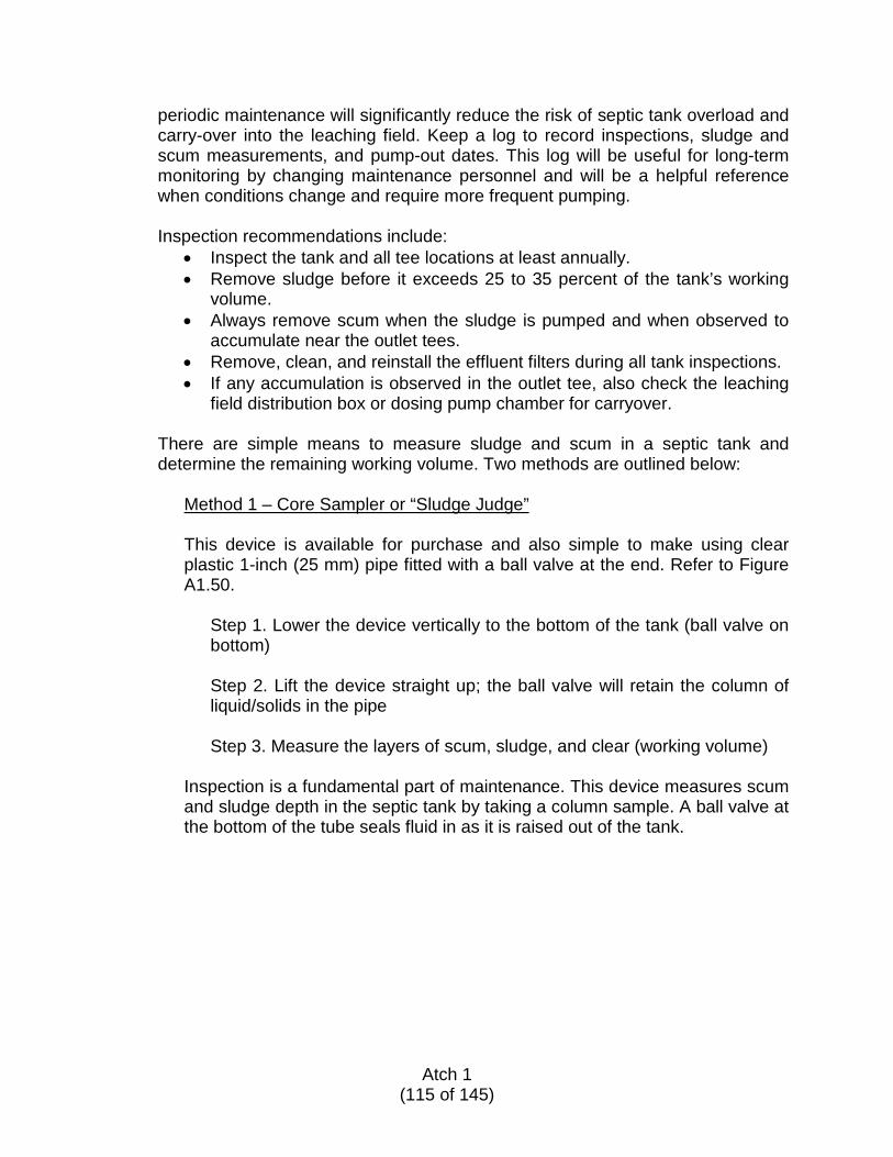
periodic maintenance will significantly reduce the risk of septic tank overload and carry-over into the leaching field. Keep a log to record inspections, sludge and scum measurements, and pump-out dates. This log will be useful for long-term monitoring by changing maintenance personnel and will be a helpful reference when conditions change and require more frequent pumping.
Inspection recommendations include:
• Inspect the tank and all tee locations at least annually. • Remove sludge before it exceeds 25 to 35 percent of the tank’s working
volume. • Always remove scum when the sludge is pumped and when observed to
accumulate near the outlet tees. • Remove, clean, and reinstall the effluent filters during all tank inspections. • If any accumulation is observed in the outlet tee, also check the leaching
field distribution box or dosing pump chamber for carryover.
There are simple means to measure sludge and scum in a septic tank and determine the remaining working volume. Two methods are outlined below:
Method 1 – Core Sampler or “Sludge Judge”
This device is available for purchase and also simple to make using clear plastic 1-inch (25 mm) pipe fitted with a ball valve at the end. Refer to Figure A1.50.
Step 1. Lower the device vertically to the bottom of the tank (ball valve on bottom) Step 2. Lift the device straight up; the ball valve will retain the column of liquid/solids in the pipe Step 3. Measure the layers of scum, sludge, and clear (working volume)
Inspection is a fundamental part of maintenance. This device measures scum and sludge depth in the septic tank by taking a column sample. A ball valve at the bottom of the tube seals fluid in as it is raised out of the tank.
Atch 1
(115 of 145)

Source: URI Extension
Figure A1.50. Use of Sludge Judge
Method 2 – Stick and Foot/Sock Device
This device includes a long stick with a 3-inch (7.6 cm) piece of wood attached across one end, forming a “foot.” The device is simple to assemble.
Step 1. Use the foot to push through the scum layer until resistance is felt from the liquid layer. Step 2. Pull out the device and measure the scum layer on the stick. Step 3. Remove the foot from the stick. Step 4. Wrap a cloth around the stick and secure with rubber bands or other method. Step 5. Lower stick through the hole made previously in the scum layer. Step 6. Push the stick down through the liquid in the tank until it hits the bottom of the tank. Step 7. Lift the stick out of the tank and measure the depth that the solids are sticking to the cloth.
Atch 1
(116 of 145)
Septic tank pump-out is required:
• If the solids layer is at or above one-third of the tank volume (depth) • If the bottom of the scum layer is within 3 inches (7.6 cm) of the bottom
of the inlet baffle • If the bottom of the scum layer is within 8 inches (20.3 cm) of the
bottom of the outlet device • If less than two-thirds of working depth remains then the tank should
be pumped out in its entirety
Procedure for tank pump-outs: • Remove the entire contents of the tank through an access port located on
top of the tank. • Do not pump out the tank through the distribution box. • Dispose of the contents of the tank in an environmentally neutral way. If
hauling offsite to a nearby WWTF is not possible, consider passive land disposal based on terrain and climate conditions.
Septic tanks are typically pumped out with a vacuum tank truck. The pumper will use a 4- to 6-inch (101 to 152 mm) -diameter hose and vacuum everything out of the tank (both solids and liquids). The septage removed should be taken to a host nation government-licensed or authorized disposal site because of potential health problems from contamination. Such sites may include evaporation ponds, sewage plants, or wastewater treatment plants that accept septage for further treatment and processing. A1.8.1.2. Leach Field O&M
After several years of use, a build-up of bottom sludge and floating scum will reduce the effective capacity of the tank. This means waste passes through the tank too quickly and solids eventually plug the pipes in the leaching field. The microorganisms in the leaching field no longer have an aerobic (with oxygen) environment in which to perform their cleansing action; they are now struggling to survive in an anaerobic (without oxygen) environment. Either untreated effluent begins surfacing on the ground or sewage backs up into the connected building drains. At this point the system has failed and a new leaching field is required. The only remedy for a non-functional leaching field is replacement. There is no evidence that commercially available enzymes or chemical treatments can revitalize a leaching field. There may be some short-term relief but the problem will return quickly upon reuse of the system. To construct a new leaching field on top of an existing field, dig trenches parallel to the existing pipes or widen the existing trenches. A1.8.1.3. Troubleshooting System Problems
Atch 1 (117 of 145)
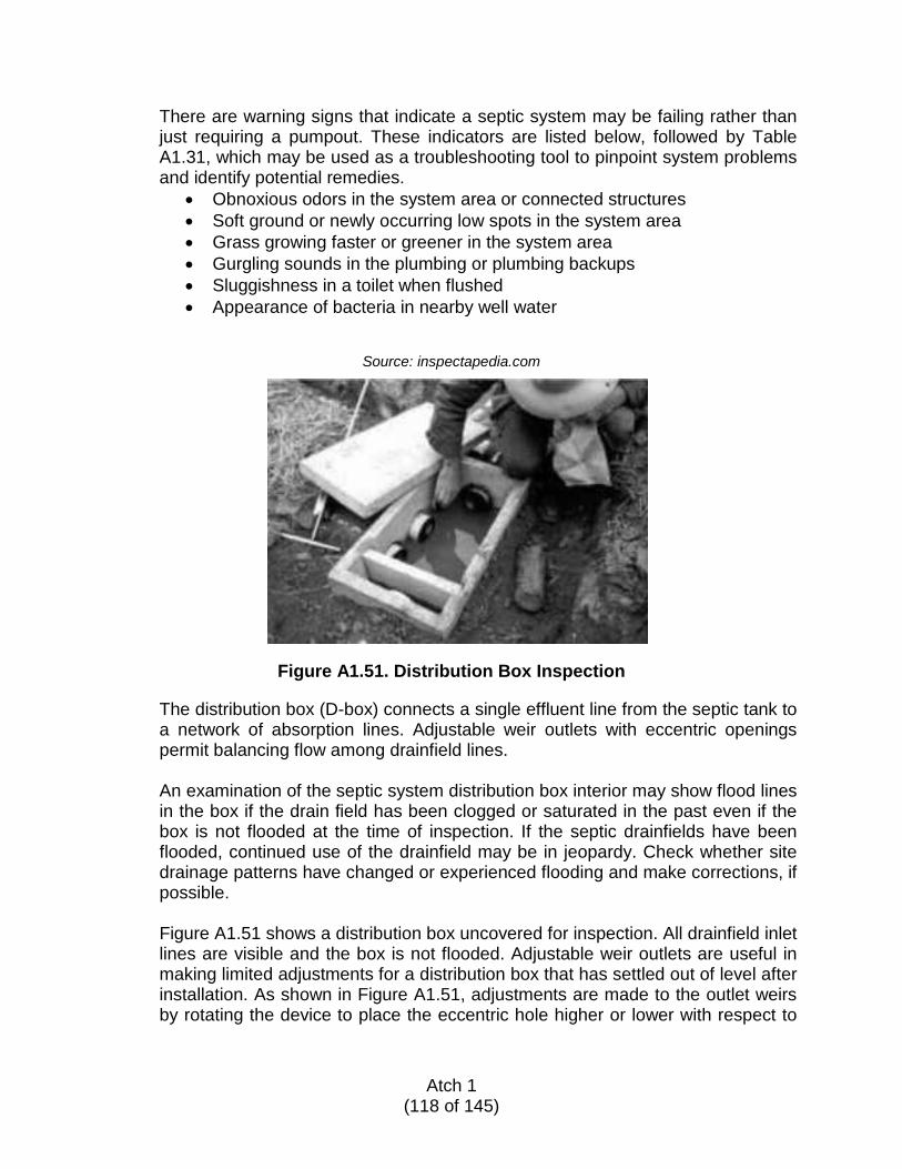
There are warning signs that indicate a septic system may be failing rather than just requiring a pumpout. These indicators are listed below, followed by Table A1.31, which may be used as a troubleshooting tool to pinpoint system problems and identify potential remedies.
• Obnoxious odors in the system area or connected structures • Soft ground or newly occurring low spots in the system area • Grass growing faster or greener in the system area • Gurgling sounds in the plumbing or plumbing backups • Sluggishness in a toilet when flushed • Appearance of bacteria in nearby well water
Source: inspectapedia.com
Figure A1.51. Distribution Box Inspection
The distribution box (D-box) connects a single effluent line from the septic tank to a network of absorption lines. Adjustable weir outlets with eccentric openings permit balancing flow among drainfield lines.
An examination of the septic system distribution box interior may show flood lines in the box if the drain field has been clogged or saturated in the past even if the box is not flooded at the time of inspection. If the septic drainfields have been flooded, continued use of the drainfield may be in jeopardy. Check whether site drainage patterns have changed or experienced flooding and make corrections, if possible. Figure A1.51 shows a distribution box uncovered for inspection. All drainfield inlet lines are visible and the box is not flooded. Adjustable weir outlets are useful in making limited adjustments for a distribution box that has settled out of level after installation. As shown in Figure A1.51, adjustments are made to the outlet weirs by rotating the device to place the eccentric hole higher or lower with respect to
Atch 1
(118 of 145)
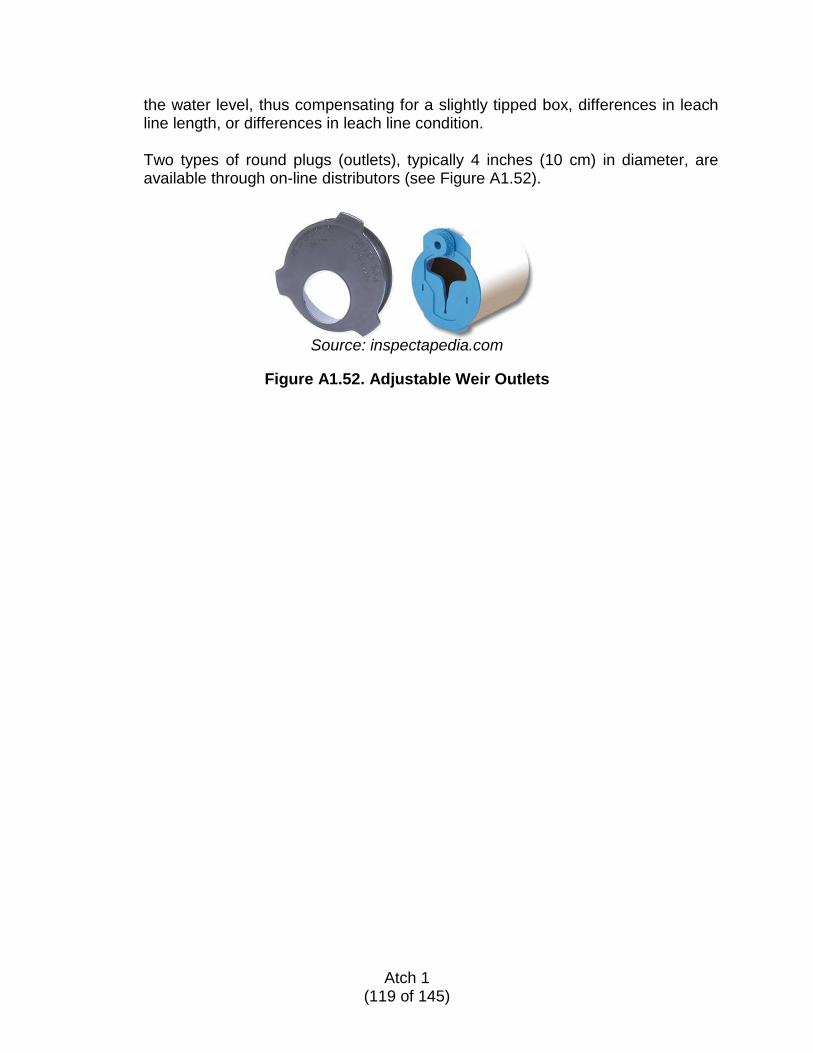
the water level, thus compensating for a slightly tipped box, differences in leach line length, or differences in leach line condition. Two types of round plugs (outlets), typically 4 inches (10 cm) in diameter, are available through on-line distributors (see Figure A1.52).
Source: inspectapedia.com
Figure A1.52. Adjustable Weir Outlets
Atch 1
(119 of 145)
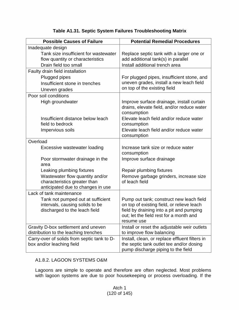
Table A1.31. Septic System Failures Troubleshooting Matrix
Possible Causes of Failure Potential Remedial Procedures Inadequate design Tank size insufficient for wastewater
flow quantity or characteristics Replace septic tank with a larger one or add additional tank(s) in parallel
Drain field too small Install additional trench area Faulty drain field installation Plugged pipes For plugged pipes, insufficient stone, and
uneven grades, install a new leach field on top of the existing field
Insufficient stone in trenches Uneven grades Poor soil conditions High groundwater Improve surface drainage, install curtain
drains, elevate field, and/or reduce water consumption
Insufficient distance below leach field to bedrock
Elevate leach field and/or reduce water consumption
Impervious soils Elevate leach field and/or reduce water consumption
Overload Excessive wastewater loading Increase tank size or reduce water
consumption Poor stormwater drainage in the
area Improve surface drainage
Leaking plumbing fixtures Repair plumbing fixtures Wastewater flow quantity and/or
characteristics greater than anticipated due to changes in use
Remove garbage grinders, increase size of leach field
Lack of tank maintenance Tank not pumped out at sufficient
intervals, causing solids to be discharged to the leach field
Pump out tank; construct new leach field on top of existing field, or relieve leach field by draining into a pit and pumping out; let the field rest for a month and resume use
Gravity D-box settlement and uneven distribution to the leaching trenches
Install or reset the adjustable weir outlets to improve flow balancing
Carry-over of solids from septic tank to D-box and/or leaching field
Install, clean, or replace effluent filters in the septic tank outlet tee and/or dosing pump discharge piping to the field
A1.8.2. LAGOON SYSTEMS O&M
Lagoons are simple to operate and therefore are often neglected. Most problems with lagoon systems are due to poor housekeeping or process overloading. If the
Atch 1
(120 of 145)
lagoon is properly designed and sized and the population it serves does not increase significantly, loading problems should not be an issue. The following paragraphs concern housekeeping issues that affect lagoon operation.
A1.8.2.1. Bar Screens
Lagoons should be provided with bar screens in their inlet structure. These screens should be inspected at least twice a day, more often during storms, and cleaned as necessary. Screenings should be disposed of immediately in a sanitary manner. One method is burial in a nearby trench, another is to place the screenings into containers with lids (e.g., garbage cans) and arrange for the containers to be emptied on a regular basis. Collected screenings should either be buried in a landfill or incinerated.
A1.8.2.2. Mixing and Aeration
Lagoons can be operated efficiently without mechanical mixing or aeration as long as they are not overloaded and the naturally occurring circulation and the oxygen supplied by suspended plant growth is sufficient to support stabilization of the organic wastes in the influent. For more heavily loaded lagoons, or for lagoons located in difficult climates, mechanical mixing and/or aeration may be required. Most systems or devices that mix or move water around require a source of electrical power. If this is not available or would be difficult to obtain, solar-powered mixer/aerators are available. These devices are floating mixers that would be anchored in the lagoon and powered by solar panels. (One source for this type of mixer is Solar Bee®). Floating mixers/aerators, however they are powered, is the best choice for lagoons, but other methods include:
• Pumped recirculation of the lagoon contents (for mixing only) • Diffused low-pressure air (aeration only; energy-intensive; not very
efficient in lagoon environments) • Use of an air-cooled outboard motor mounted on a small boat
Regardless of the system in use, the operator should match the mixer/aerator operating time with the dissolved oxygen (DO) requirements of the lagoon. Too much DO is not better than just enough and, as it also wastes energy and incurs needless wear on the equipment, it is not a good practice to over-mix or over-aerate the lagoon contents.
A1.8.2.3. Scum Control
Scum accumulation is common in lagoons—more so in the spring in temperate climates when biological activity resumes as water temperature rises. Wind often dissipates scum accumulations, but, in the absence of wind, or in sheltered areas, mechanical means must be used to break up the scum. Scum accumulations should be addressed in a timely manner because if they are
Atch 1
(121 of 145)
allowed to remain, over time the scum can cause objectionable odors and may dry out and become crusted, making it more difficult to break up.
Scum may be broken up with rakes or jets of water from the shore or with rakes from boats. Outboard motors can also be used as a means of breaking up scum layers but they should be air-cooled as water-cooled motors can easily be plugged with algae and scum.
A1.8.2.4. Odor Control
Most incidents of odor generation in a lagoon result from either overloading or poor maintenance. Process upsets caused by unexpected shutdowns can also trigger an odor event. If overloading is suspected, diversion of the influent to another treatment source (e.g., a second lagoon) will allow time for the odor to resolve itself. Loading can be gradually resumed after the odor subsides. Other effective measures to reduce odor include the following:
• Adding chlorine • Providing mechanical aeration • Odor-masking agents are another possibility, but, in the long run they are
less effective than the remedies noted above • Sodium nitrate can also be used to reduce odors, but it must be dispersed
throughout the pond to be effective
There are a few items to note regarding the effectiveness of the above-listed remedies. Unless chlorination equipment or floating aerators are already on hand, it could be difficult to acquire and install the necessary equipment to aerate and/or chlorinate in a timely manner. Also, sodium nitrate provides a source of oxygen for the facultative organisms in the lagoon and does not interfere with biological activity like chlorine or sodium hypochlorite. Regardless of the method chosen to address odor issues, it is not wise to wait until an odor situation arises before deciding what to do about it. Prior planning related to addressing an odor incident allows the operator to react quickly without having to decide what to do and then try to quickly locate the necessary equipment and/or chemicals.
A1.8.2.5. Weed and Insect Control
Weed control is an essential part of lagoon maintenance. There are three areas of concern:
1. The lagoon levee 2. The shallow areas on the edge of the lagoon 3. Suspended vegetation growing on the water’s surface
Basic control of weeds on the levee consists of a program of regular mowing combined with planting grasses that choke out weeds. The use of herbicides
Atch 1
(122 of 145)
should be considered only as a last resort. Placement of riprap or the installation of a lagoon liner can be considered to reduce or eliminate unwanted growth on the sloped portion of the levee. Shallow water vegetation (e.g., tules) can be reduced or eliminated by maintaining the lagoon depth at 3 feet (1 m) or greater. For vegetation control in edge areas where this may not be possible:
• Prompt removal of emergent vegetation, including the roots, is the best means of control; or
• Manipulate the level in the lagoon to either expose vegetation for removal or drown it; or
• Burning them out with a gas burner is also an option.
Without lagoon edge vegetation the likelihood of insect propagation will be greatly reduced. When removing emergent growth be sure to wear the appropriate gear, including approved flotation devices and work safely. CAUTION: Do not work alone on the edge of a lagoon or in a boat. Drowning after a slip or fall is always a possibility. Suspended vegetation (e.g., duckweed) will not flourish in a lagoon exposed to wind. Any established suspended vegetation should be removed, typically by collecting it with rakes or other implements while in a boat if it is not reachable from the shore. Mosquitoes commonly breed in sheltered water areas with vegetation or scum where the female mosquito can attach her egg rafts. If the scum is broken up or removed and the vegetation is removed, the fragile mosquito egg rafts will not survive. Small mosquito fish can also be introduced for mosquito control. Midges, when present, are best controlled by insecticides. If it becomes necessary to use an insecticide, check with local authorities to find out which insecticides are acceptable. Always follow safe application procedures, including ambient conditions necessary for safely and effectively applying the insecticide.
A1.8.2.6. Levee Maintenance
Levees may be eroded by:
• Wave action or surface runoff during rain storms • Animal burrows, which can compromise the integrity of a levee bank
The levee should be inspected at regular intervals, looking for signs of erosion or animal burrows. If erosion is a continuous problem, consider installing bank protection:
• Riprap or stone/broken concrete rubble • Semi-porous plastic sheeting can be useful if properly installed in
conjunction with riprap • Evict any burrowing animals found and fill in their burrows
Atch 1
(123 of 145)
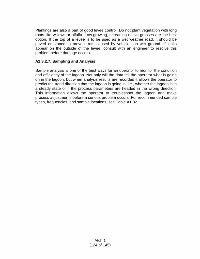
Plantings are also a part of good levee control. Do not plant vegetation with long roots like willows or alfalfa. Low-growing, spreading native grasses are the best option. If the top of a levee is to be used as a wet weather road, it should be paved or stoned to prevent ruts caused by vehicles on wet ground. If leaks appear on the outside of the levee, consult with an engineer to resolve this problem before damage occurs.
A1.8.2.7. Sampling and Analysis
Sample analysis is one of the best ways for an operator to monitor the condition and efficiency of the lagoon. Not only will the data tell the operator what is going on in the lagoon, but when analysis results are recorded it allows the operator to predict the trend direction that the lagoon is going in, i.e., whether the lagoon is in a steady state or if the process parameters are headed in the wrong direction. This information allows the operator to troubleshoot the lagoon and make process adjustments before a serious problem occurs. For recommended sample types, frequencies, and sample locations, see Table A1.32.
Atch 1
(124 of 145)
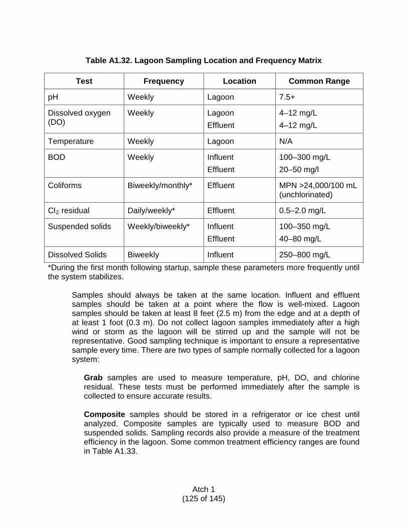
Table A1.32. Lagoon Sampling Location and Frequency Matrix
Test Frequency Location Common Range
pH Weekly Lagoon 7.5+
Dissolved oxygen (DO)
Weekly Lagoon Effluent
4–12 mg/L 4–12 mg/L
Temperature Weekly Lagoon N/A
BOD Weekly Influent Effluent
100–300 mg/L 20–50 mg/l
Coliforms Biweekly/monthly* Effluent MPN >24,000/100 mL (unchlorinated)
Cl2 residual Daily/weekly* Effluent 0.5–2.0 mg/L
Suspended solids Weekly/biweekly* Influent Effluent
100–350 mg/L 40–80 mg/L
Dissolved Solids Biweekly Influent 250–800 mg/L *During the first month following startup, sample these parameters more frequently until the system stabilizes.
Samples should always be taken at the same location. Influent and effluent samples should be taken at a point where the flow is well-mixed. Lagoon samples should be taken at least 8 feet (2.5 m) from the edge and at a depth of at least 1 foot (0.3 m). Do not collect lagoon samples immediately after a high wind or storm as the lagoon will be stirred up and the sample will not be representative. Good sampling technique is important to ensure a representative sample every time. There are two types of sample normally collected for a lagoon system:
Grab samples are used to measure temperature, pH, DO, and chlorine residual. These tests must be performed immediately after the sample is collected to ensure accurate results. Composite samples should be stored in a refrigerator or ice chest until analyzed. Composite samples are typically used to measure BOD and suspended solids. Sampling records also provide a measure of the treatment efficiency in the lagoon. Some common treatment efficiency ranges are found in Table A1.33.
Atch 1
(125 of 145)
Table A1.33. Lagoon Expected Ranges of Removal
Parameter Detention Time Expected Removal
BOD (total range)
50 to 100 days 50% to 90%
BOD (facultative lagoon)
50 to 60 days 70% to 80%
Coliform bacteria (facultative lagoon)
50 to 60 days 90% to 95%
Suspended solids Dissolved organic solids
After 3 days After 10 days
90% 80%
DO, pH, and temperature are important indicators to determine lagoon conditions. BOD, coliform, and solids testing measure the lagoon treatment efficiency.
A1.8.2.8. Troubleshooting System Problems
There are warning signs that indicate a lagoon system may be overloaded. These indicators are listed below, followed by Table A1.34, which may be used as a troubleshooting tool to pinpoint system problems and identify potential remedies.
• Obnoxious odors in the area of the lagoon • Sudden changes in pH or DO • Rapid change in pond surface appearance (color) • Large amount of black or brown scum
Atch 1
(126 of 145)
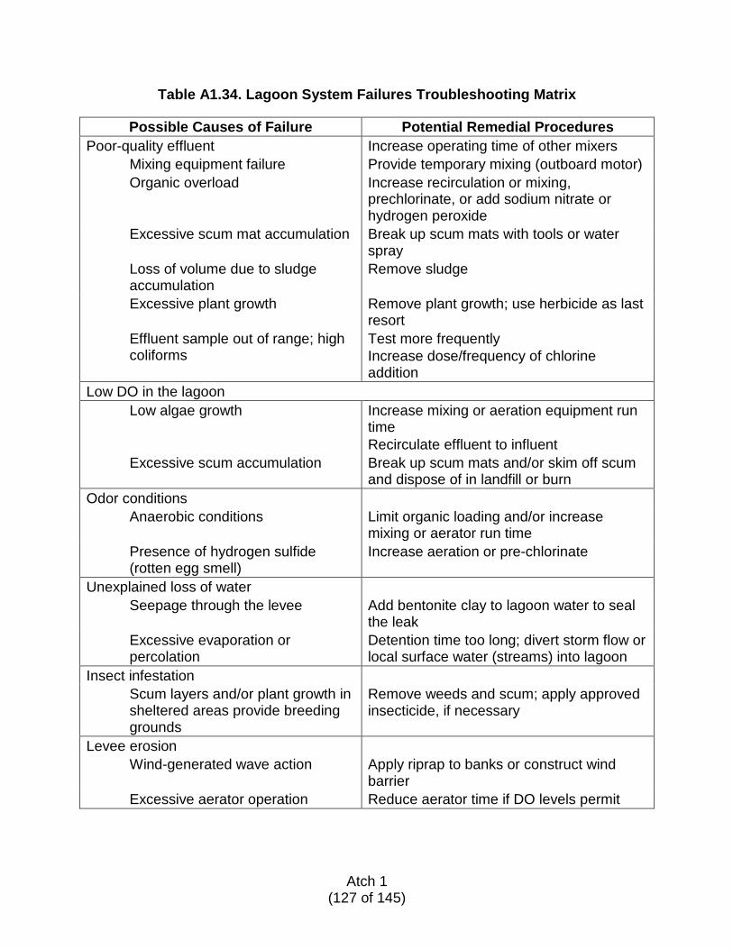
Table A1.34. Lagoon System Failures Troubleshooting Matrix
Possible Causes of Failure Potential Remedial Procedures Poor-quality effluent Increase operating time of other mixers Mixing equipment failure Provide temporary mixing (outboard motor) Organic overload Increase recirculation or mixing,
prechlorinate, or add sodium nitrate or hydrogen peroxide
Excessive scum mat accumulation Break up scum mats with tools or water spray
Loss of volume due to sludge accumulation
Remove sludge
Excessive plant growth Remove plant growth; use herbicide as last resort
Effluent sample out of range; high coliforms
Test more frequently Increase dose/frequency of chlorine addition
Low DO in the lagoon Low algae growth Increase mixing or aeration equipment run
time Recirculate effluent to influent
Excessive scum accumulation Break up scum mats and/or skim off scum and dispose of in landfill or burn
Odor conditions Anaerobic conditions Limit organic loading and/or increase
mixing or aerator run time Presence of hydrogen sulfide (rotten egg smell)
Increase aeration or pre-chlorinate
Unexplained loss of water Seepage through the levee Add bentonite clay to lagoon water to seal
the leak Excessive evaporation or percolation
Detention time too long; divert storm flow or local surface water (streams) into lagoon
Insect infestation Scum layers and/or plant growth in sheltered areas provide breeding grounds
Remove weeds and scum; apply approved insecticide, if necessary
Levee erosion Wind-generated wave action Apply riprap to banks or construct wind
barrier Excessive aerator operation Reduce aerator time if DO levels permit
Atch 1
(127 of 145)
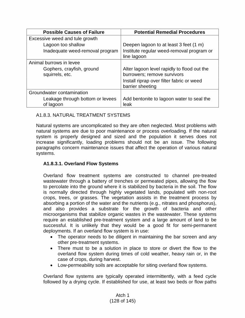
Possible Causes of Failure Potential Remedial Procedures Excessive weed and tule growth Lagoon too shallow Deepen lagoon to at least 3 feet (1 m) Inadequate weed-removal program Institute regular weed-removal program or
line lagoon Animal burrows in levee Gophers, crayfish, ground squirrels, etc.
Alter lagoon level rapidly to flood out the burrowers; remove survivors Install riprap over filter fabric or weed barrier sheeting
Groundwater contamination Leakage through bottom or levees of lagoon
Add bentonite to lagoon water to seal the leak
A1.8.3. NATURAL TREATMENT SYSTEMS
Natural systems are uncomplicated so they are often neglected. Most problems with natural systems are due to poor maintenance or process overloading. If the natural system is properly designed and sized and the population it serves does not increase significantly, loading problems should not be an issue. The following paragraphs concern maintenance issues that affect the operation of various natural systems.
A1.8.3.1. Overland Flow Systems
Overland flow treatment systems are constructed to channel pre-treated wastewater through a battery of trenches or permeated pipes, allowing the flow to percolate into the ground where it is stabilized by bacteria in the soil. The flow is normally directed through highly vegetated lands, populated with non-root crops, trees, or grasses. The vegetation assists in the treatment process by absorbing a portion of the water and the nutrients (e.g., nitrates and phosphorus), and also provides a substrate for the growth of bacteria and other microorganisms that stabilize organic wastes in the wastewater. These systems require an established pre-treatment system and a large amount of land to be successful. It is unlikely that they would be a good fit for semi-permanent deployments. If an overland flow system is in use:
• The operator needs to be diligent in maintaining the bar screen and any other pre-treatment systems.
• There must to be a solution in place to store or divert the flow to the overland flow system during times of cold weather, heavy rain or, in the case of crops, during harvest.
• Low-permeability soils are acceptable for siting overland flow systems.
Overland flow systems are typically operated intermittently, with a feed cycle followed by a drying cycle. If established for use, at least two beds or flow paths
Atch 1
(128 of 145)
are required so that one is always available. BOD loading is limited to 85 pounds/acre/day (95.4 kg/hectare/day).
A1.8.3.2. Constructed Wetlands (CW)
Wetlands are nature’s sewage treatment plants. It is not recommended nor usually permitted to discharge wastewater into a naturally occurring wetland due to the potential for environmental damage to the natural ecosystem; however, it is permissible and even desirable to discharge pre-treated wastewater into CW designed and built specifically to treat wastewater. CW may either be of the surface flow type or subsurface flow type. The surface flow type has exposed water that can support mosquito breeding while the subsurface flow type does not. Different types of vegetation are required by the two types or wetlands, with reeds and bulrushes typically planted in the subsurface flow type due to their deep penetrating rhizomes. Cattails, sedges, rushes, reeds, and bulrushes all grow well in exposed water wetlands. All of these plants tolerate freezing conditions and do not normally require harvesting; however, dried grasses in surface water systems may occasionally be burned off.
Vegetation assists in the treatment process by:
• Providing oxygen though the root systems • Providing a substrate for the growth of bacteria and other microorganisms
that stabilize organic wastes in the wastewater
These systems require an established pre-treatment system and a large amount of land to be successful. If a CW system is in use, the operator needs to be diligent in maintaining the bar screen and any other pre-treatment systems. There needs to be a solution in place to store or divert the flow to the CW system during cold weather. Low-permeability soils are acceptable for siting CW. BOD loading is limited to 100 pounds/acre/day (112 kg/hectare/day) for subsurface flow systems and 60 pounds/acre/day (67 kg/hectare/day) for surface flow types. Phosphorus removal in constructed wetlands is not significant.
A1.8.3.3. Irrigation-Based Systems
Irrigation-based systems are similar to overland flow systems (see paragraph A1.8.3.1) in that they must be preceded by pre-treatment processes and are dependent upon vegetation for a significant portion of treatment and nutrient uptake. Influent distribution is accomplished by sprinklers, surface application, or a drip system. These systems require an established pre-treatment system and a large amount of land to be successful. It is unlikely that they would be a good fit for semi-permanent deployments. If an irrigation-based system is in use, the operator needs to be diligent in maintaining the bar screen and any other pre-treatment systems as a high-quality influent is required to avoid plugging sprinklers or drip systems. A solution needs to be in place to store or divert the flow to the irrigation system during cold weather, heavy rain or, in the case of
Atch 1
(129 of 145)
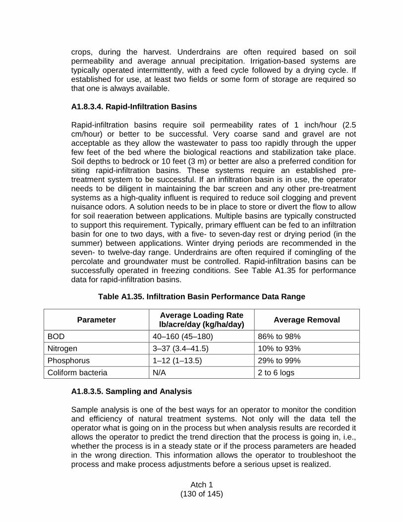
crops, during the harvest. Underdrains are often required based on soil permeability and average annual precipitation. Irrigation-based systems are typically operated intermittently, with a feed cycle followed by a drying cycle. If established for use, at least two fields or some form of storage are required so that one is always available. A1.8.3.4. Rapid-Infiltration Basins
Rapid-infiltration basins require soil permeability rates of 1 inch/hour (2.5 cm/hour) or better to be successful. Very coarse sand and gravel are not acceptable as they allow the wastewater to pass too rapidly through the upper few feet of the bed where the biological reactions and stabilization take place. Soil depths to bedrock or 10 feet (3 m) or better are also a preferred condition for siting rapid-infiltration basins. These systems require an established pre-treatment system to be successful. If an infiltration basin is in use, the operator needs to be diligent in maintaining the bar screen and any other pre-treatment systems as a high-quality influent is required to reduce soil clogging and prevent nuisance odors. A solution needs to be in place to store or divert the flow to allow for soil reaeration between applications. Multiple basins are typically constructed to support this requirement. Typically, primary effluent can be fed to an infiltration basin for one to two days, with a five- to seven-day rest or drying period (in the summer) between applications. Winter drying periods are recommended in the seven- to twelve-day range. Underdrains are often required if comingling of the percolate and groundwater must be controlled. Rapid-infiltration basins can be successfully operated in freezing conditions. See Table A1.35 for performance data for rapid-infiltration basins.
Table A1.35. Infiltration Basin Performance Data Range
Parameter Average Loading Rate lb/acre/day (kg/ha/day) Average Removal
BOD 40–160 (45–180) 86% to 98% Nitrogen 3–37 (3.4–41.5) 10% to 93% Phosphorus 1–12 (1–13.5) 29% to 99% Coliform bacteria N/A 2 to 6 logs
A1.8.3.5. Sampling and Analysis
Sample analysis is one of the best ways for an operator to monitor the condition and efficiency of natural treatment systems. Not only will the data tell the operator what is going on in the process but when analysis results are recorded it allows the operator to predict the trend direction that the process is going in, i.e., whether the process is in a steady state or if the process parameters are headed in the wrong direction. This information allows the operator to troubleshoot the process and make process adjustments before a serious upset is realized.
Atch 1
(130 of 145)
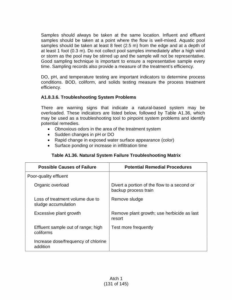
Samples should always be taken at the same location. Influent and effluent samples should be taken at a point where the flow is well-mixed. Aquatic pool samples should be taken at least 8 feet (2.5 m) from the edge and at a depth of at least 1 foot (0.3 m). Do not collect pool samples immediately after a high wind or storm as the pool may be stirred up and the sample will not be representative. Good sampling technique is important to ensure a representative sample every time. Sampling records also provide a measure of the treatment’s efficiency.
DO, pH, and temperature testing are important indicators to determine process conditions. BOD, coliform, and solids testing measure the process treatment efficiency.
A1.8.3.6. Troubleshooting System Problems
There are warning signs that indicate a natural-based system may be overloaded. These indicators are listed below, followed by Table A1.36, which may be used as a troubleshooting tool to pinpoint system problems and identify potential remedies.
• Obnoxious odors in the area of the treatment system • Sudden changes in pH or DO • Rapid change in exposed water surface appearance (color) • Surface ponding or increase in infiltration time
Table A1.36. Natural System Failure Troubleshooting Matrix
Possible Causes of Failure Potential Remedial Procedures
Poor-quality effluent
Organic overload Divert a portion of the flow to a second or backup process train
Loss of treatment volume due to sludge accumulation
Remove sludge
Excessive plant growth Remove plant growth; use herbicide as last resort
Effluent sample out of range; high coliforms
Test more frequently
Increase dose/frequency of chlorine addition
Atch 1
(131 of 145)
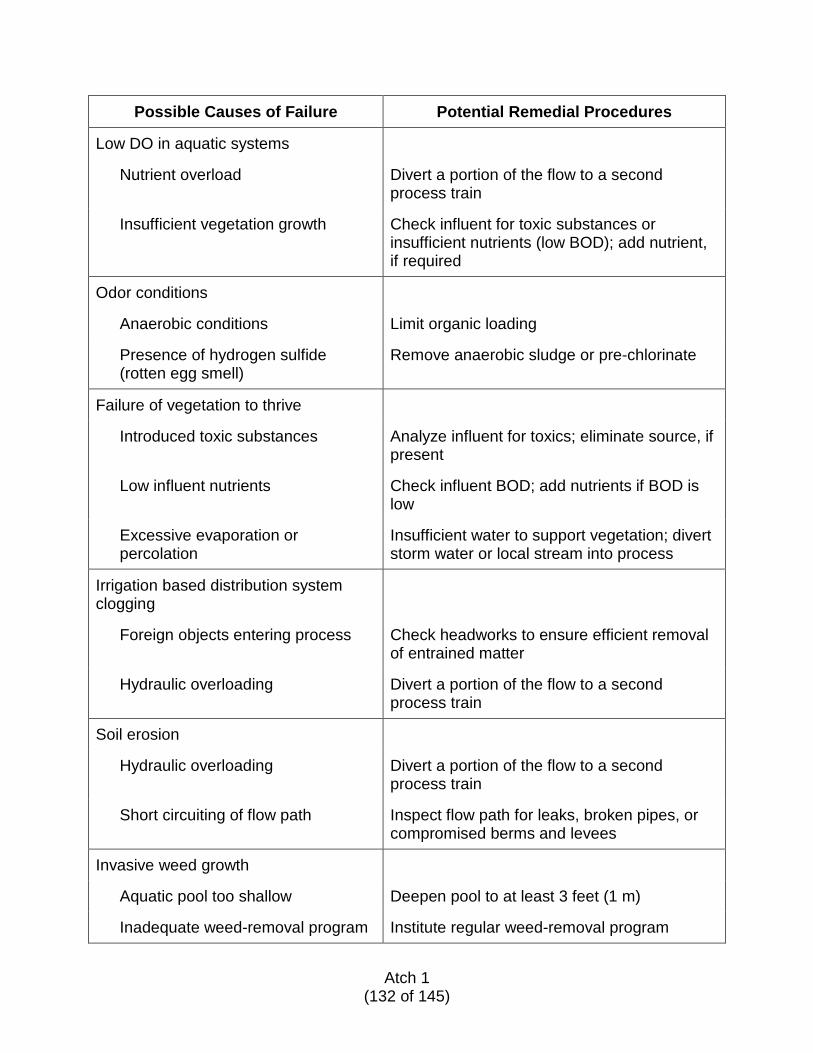
Possible Causes of Failure Potential Remedial Procedures
Low DO in aquatic systems
Nutrient overload Divert a portion of the flow to a second process train
Insufficient vegetation growth Check influent for toxic substances or insufficient nutrients (low BOD); add nutrient, if required
Odor conditions
Anaerobic conditions Limit organic loading
Presence of hydrogen sulfide (rotten egg smell)
Remove anaerobic sludge or pre-chlorinate
Failure of vegetation to thrive
Introduced toxic substances Analyze influent for toxics; eliminate source, if present
Low influent nutrients Check influent BOD; add nutrients if BOD is low
Excessive evaporation or percolation
Insufficient water to support vegetation; divert storm water or local stream into process
Irrigation based distribution system clogging
Foreign objects entering process Check headworks to ensure efficient removal of entrained matter
Hydraulic overloading Divert a portion of the flow to a second process train
Soil erosion
Hydraulic overloading Divert a portion of the flow to a second process train
Short circuiting of flow path Inspect flow path for leaks, broken pipes, or compromised berms and levees
Invasive weed growth
Aquatic pool too shallow Deepen pool to at least 3 feet (1 m)
Inadequate weed-removal program Institute regular weed-removal program
Atch 1
(132 of 145)
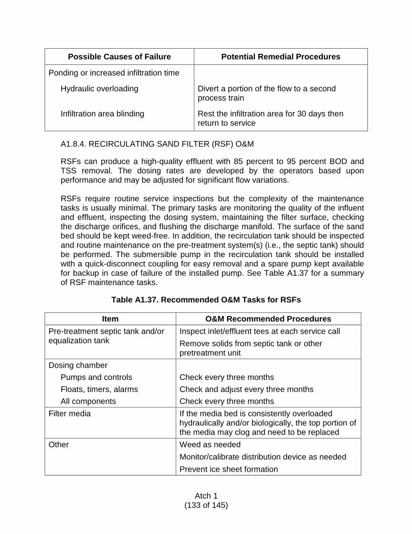
Possible Causes of Failure Potential Remedial Procedures
Ponding or increased infiltration time
Hydraulic overloading Divert a portion of the flow to a second process train
Infiltration area blinding Rest the infiltration area for 30 days then return to service
A1.8.4. RECIRCULATING SAND FILTER (RSF) O&M
RSFs can produce a high-quality effluent with 85 percent to 95 percent BOD and TSS removal. The dosing rates are developed by the operators based upon performance and may be adjusted for significant flow variations. RSFs require routine service inspections but the complexity of the maintenance tasks is usually minimal. The primary tasks are monitoring the quality of the influent and effluent, inspecting the dosing system, maintaining the filter surface, checking the discharge orifices, and flushing the discharge manifold. The surface of the sand bed should be kept weed-free. In addition, the recirculation tank should be inspected and routine maintenance on the pre-treatment system(s) (i.e., the septic tank) should be performed. The submersible pump in the recirculation tank should be installed with a quick-disconnect coupling for easy removal and a spare pump kept available for backup in case of failure of the installed pump. See Table A1.37 for a summary of RSF maintenance tasks.
Table A1.37. Recommended O&M Tasks for RSFs
Item O&M Recommended Procedures
Pre-treatment septic tank and/or equalization tank
Inspect inlet/effluent tees at each service call Remove solids from septic tank or other pretreatment unit
Dosing chamber Pumps and controls Check every three months Floats, timers, alarms Check and adjust every three months All components Check every three months
Filter media If the media bed is consistently overloaded hydraulically and/or biologically, the top portion of the media may clog and need to be replaced
Other Weed as needed Monitor/calibrate distribution device as needed Prevent ice sheet formation
Atch 1
(133 of 145)
A1.8.5. COMMERCIAL TREATMENT SYSTEMS
Commercial treatment systems are often called “package plants.” While the activated sludge process is not a proprietary product, many manufacturers of package plants develop unique process features and/or equipment that may be trademark-protected. For this reason, each supplier has their own unique operating requirements. The owner/operator of a proprietary system will be supplied with printed copies of the O&M instructions for that unit. Operator training is often provided as part of the purchased package. These instructions need to be kept where they can be consulted as needed and filed for future use. Consult the proprietary system instructions for O&M information relating to the installed system.
A1.8.5.1. Biological Process Startup
There are many variations of biological treatment processes. All biological processes have one common element: they utilize microorganisms to remove organic constituents (contaminants) from wastewater. These microorganisms occur naturally in wastewater but in insufficient numbers to provide treatment. Certain conditions are needed to encourage growth of these microorganisms and thus support treatment in a process tank. This can be done in one of two ways: by seeding or by developing a population of microorganisms from scratch. In either case, the following conditions are necessary for the success of biological treatment:
• Adequate supply of oxygen for the microorganisms • Adequate nutrients (food) to support growth of the microorganism
population • Mixing in the reactor to bring the oxygen and food in contact with the
microorganisms
A1.8.5.2. Seeded Startup
Seeding is the fastest and easiest method for bringing a new biological process online or for rejuvenating an existing process that has undergone a process upset that killed all or most of the microorganisms. A nearby source of mixed liquor or activated sludge is an essential part of a seeded startup. A seeded startup is impossible without the ability to import existing mixed liquor into the facility. Assuming the seed is available, a basic procedure for a seeded start is as follows:
1. Fill (or nearly fill) the reactor with water (if not already filled). 2. Aerate the contents of the reactor until the DO is at least 2.0 mg/L.
Aerating over 4.0 mg/L is a waste of energy and will not help the process (more is not better).
Atch 1
(134 of 145)
3. If there is a separate method of mixing the reactor, other than the introduction of air, start it now.
4. Introduce raw wastewater or pretreatment (septic tank) effluent concurrently with the seed sludge. How much seed to use? Anything is better than none but, as most seed will be around 10,000 mg/L in concentration, the volume of seed added should never be more than an amount that would exceed 2,000 mg/L suspended solids concentration in the reactor(s). An easy calculation is to multiply the ADF by 8.34 x 0.02 ÷ 8.34. For a 3,000-gpd plant, this would equal 60 gallons of seed. Note: Unless your facility is extremely small, it is unlikely you would have the ability to economically transfer that much seed.
5. Note that the existing DO will be consumed when organic wastes and microorganisms are added to the reactor. Monitor the DO closely at this time and adjust the aeration rate as required to maintain 2.0 mg/L DO concentration. Note: It is not unusual to see white, fluffy foam during a process startup. This is normal and will disappear as the mixed liquor suspended solids (MLSS) concentration increases.
6. It is not necessary to fill the clarifier (if present) completely prior to startup; one-quarter to one-third of the volume is fine. Once the reactor effluent begins to enter the clarifier, start the collector mechanism.
7. Whatever means of recirculating the reactor effluent mixed liquor, begin doing so at a rate of 1.5 times the influent flow as soon as it is possible to do so.
8. Measure DO and MLSS at least twice a day—twice per shift, if possible. Maintain the DO at 2.0 mg/L and monitor the MLSS.
9. When the MLSS nears 2,000 mg/L, reduce the recirculation rate back to whatever the design rate is for your process.
10. Increasing the mixed liquor concentration to 2,000 mg/L MLSS (typically the minimum required for an extended-aeration WWTF) will take anywhere from two to five days, depending on the following factors:
• Amount and concentration of seed used • Strength of the reactor influent • Temperature of the reactor contents • Maintaining DO and adequate mixing in the reactor
A1.8.5.3. Unseeded Startup
The steps for an unseeded startup, or restart, are exactly the same except there is no seed. Because there is no seed, it will take from one to three weeks to develop a population of microorganisms at the design concentration, dependent upon the strength of the reactor influent and the temperature of the process. The task of the operator is to oversee the process to ensure the variables they can control are kept within normal limits and to monitor the progress of biological growth within the reactor.
Atch 1
(135 of 145)
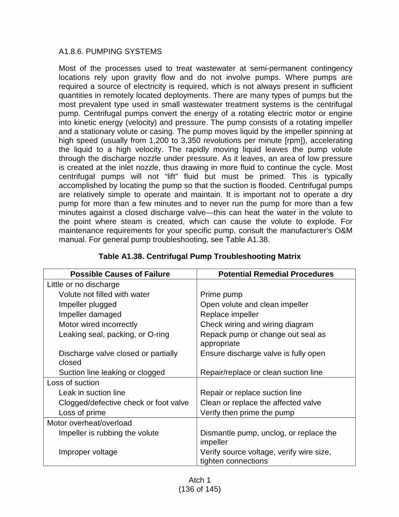
A1.8.6. PUMPING SYSTEMS
Most of the processes used to treat wastewater at semi-permanent contingency locations rely upon gravity flow and do not involve pumps. Where pumps are required a source of electricity is required, which is not always present in sufficient quantities in remotely located deployments. There are many types of pumps but the most prevalent type used in small wastewater treatment systems is the centrifugal pump. Centrifugal pumps convert the energy of a rotating electric motor or engine into kinetic energy (velocity) and pressure. The pump consists of a rotating impeller and a stationary volute or casing. The pump moves liquid by the impeller spinning at high speed (usually from 1,200 to 3,350 revolutions per minute [rpm]), accelerating the liquid to a high velocity. The rapidly moving liquid leaves the pump volute through the discharge nozzle under pressure. As it leaves, an area of low pressure is created at the inlet nozzle, thus drawing in more fluid to continue the cycle. Most centrifugal pumps will not “lift” fluid but must be primed. This is typically accomplished by locating the pump so that the suction is flooded. Centrifugal pumps are relatively simple to operate and maintain. It is important not to operate a dry pump for more than a few minutes and to never run the pump for more than a few minutes against a closed discharge valve—this can heat the water in the volute to the point where steam is created, which can cause the volute to explode. For maintenance requirements for your specific pump, consult the manufacturer’s O&M manual. For general pump troubleshooting, see Table A1.38.
Table A1.38. Centrifugal Pump Troubleshooting Matrix
Possible Causes of Failure Potential Remedial Procedures
Little or no discharge Volute not filled with water Prime pump Impeller plugged Open volute and clean impeller Impeller damaged Replace impeller Motor wired incorrectly Check wiring and wiring diagram Leaking seal, packing, or O-ring Repack pump or change out seal as
appropriate Discharge valve closed or partially closed
Ensure discharge valve is fully open
Suction line leaking or clogged Repair/replace or clean suction line Loss of suction
Leak in suction line Repair or replace suction line Clogged/defective check or foot valve Clean or replace the affected valve Loss of prime Verify then prime the pump
Motor overheat/overload Impeller is rubbing the volute Dismantle pump, unclog, or replace the
impeller Improper voltage Verify source voltage, verify wire size,
tighten connections
Atch 1 (136 of 145)
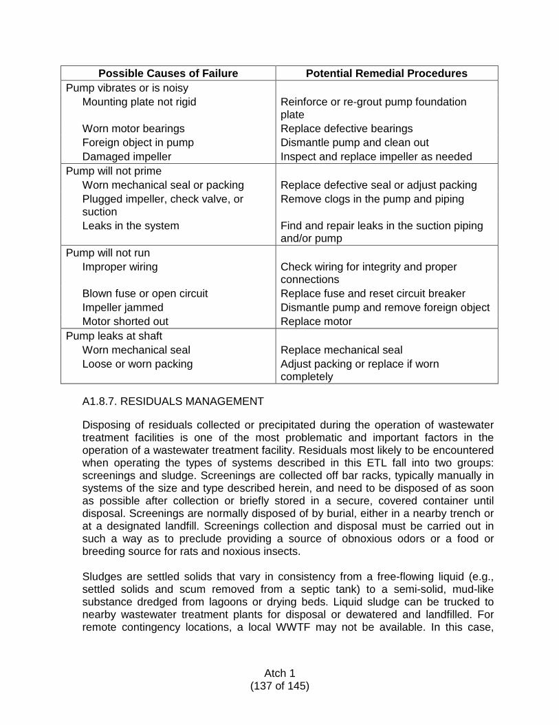
Possible Causes of Failure Potential Remedial Procedures Pump vibrates or is noisy
Mounting plate not rigid Reinforce or re-grout pump foundation plate
Worn motor bearings Replace defective bearings Foreign object in pump Dismantle pump and clean out Damaged impeller Inspect and replace impeller as needed
Pump will not prime Worn mechanical seal or packing Replace defective seal or adjust packing Plugged impeller, check valve, or suction
Remove clogs in the pump and piping
Leaks in the system Find and repair leaks in the suction piping and/or pump
Pump will not run Improper wiring Check wiring for integrity and proper
connections Blown fuse or open circuit Replace fuse and reset circuit breaker Impeller jammed Dismantle pump and remove foreign object Motor shorted out Replace motor
Pump leaks at shaft Worn mechanical seal Replace mechanical seal Loose or worn packing Adjust packing or replace if worn
completely
A1.8.7. RESIDUALS MANAGEMENT
Disposing of residuals collected or precipitated during the operation of wastewater treatment facilities is one of the most problematic and important factors in the operation of a wastewater treatment facility. Residuals most likely to be encountered when operating the types of systems described in this ETL fall into two groups: screenings and sludge. Screenings are collected off bar racks, typically manually in systems of the size and type described herein, and need to be disposed of as soon as possible after collection or briefly stored in a secure, covered container until disposal. Screenings are normally disposed of by burial, either in a nearby trench or at a designated landfill. Screenings collection and disposal must be carried out in such a way as to preclude providing a source of obnoxious odors or a food or breeding source for rats and noxious insects. Sludges are settled solids that vary in consistency from a free-flowing liquid (e.g., settled solids and scum removed from a septic tank) to a semi-solid, mud-like substance dredged from lagoons or drying beds. Liquid sludge can be trucked to nearby wastewater treatment plants for disposal or dewatered and landfilled. For remote contingency locations, a local WWTF may not be available. In this case,
Atch 1
(137 of 145)
dewatering the septage in an onsite sludge-drying bed may be necessary prior to disposal. Dewatered or semi-solid sludge can be landfilled or used as a fertilizer or soil supplement, depending upon its content and local conditions. Sludge applied to agricultural land should be plowed in as soon as possible following application.
A1.8.7.1. Sludge Drying Beds
Dewatering in a sludge drying bed occurs by evaporation from the surface of the sludge and draining from the lower layers of the sludge (the liquid that drains from the sludge is called leachate). Typical advantages of these beds are:
• Low cost • Low maintenance requirements • A high dried solids-content product • The dried product may be landfilled or buried
Disadvantages of sludge drying beds include:
• Relatively high space requirements • Potential odors • Attraction of pests • Manual removal of dried sludge
A moisture content of 60 percent can be achieved in 10 to 15 days under favorable conditions. Since most of the water is removed from the sludge by evaporation, sludge drying beds are best applied in warm, arid, and semi-arid climates. Sludge in drying beds which is exposed to precipitation will take longer to reach the desired solids content. Covering the drying bed with a roof, plastic, or glass will improve performance. Any cover should still allow air to circulate. Transparent covers, such as plastic or glass, that allow sunlight may also shorten drying time.
Atch 1
(138 of 145)
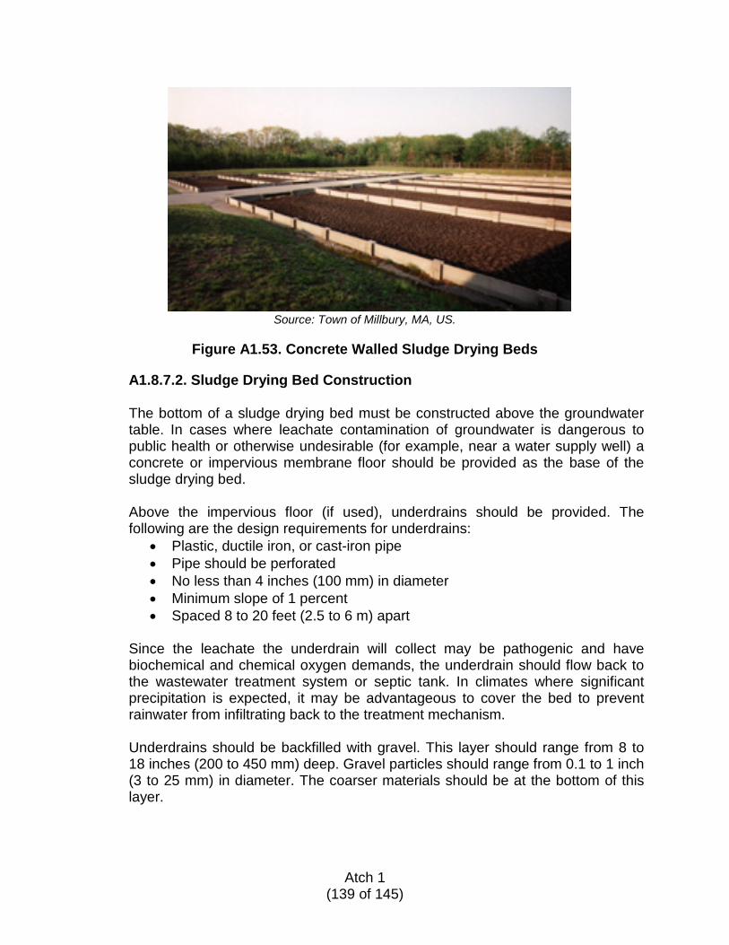
Source: Town of Millbury, MA, US.
Figure A1.53. Concrete Walled Sludge Drying Beds
A1.8.7.2. Sludge Drying Bed Construction
The bottom of a sludge drying bed must be constructed above the groundwater table. In cases where leachate contamination of groundwater is dangerous to public health or otherwise undesirable (for example, near a water supply well) a concrete or impervious membrane floor should be provided as the base of the sludge drying bed. Above the impervious floor (if used), underdrains should be provided. The following are the design requirements for underdrains:
• Plastic, ductile iron, or cast-iron pipe • Pipe should be perforated • No less than 4 inches (100 mm) in diameter • Minimum slope of 1 percent • Spaced 8 to 20 feet (2.5 to 6 m) apart
Since the leachate the underdrain will collect may be pathogenic and have biochemical and chemical oxygen demands, the underdrain should flow back to the wastewater treatment system or septic tank. In climates where significant precipitation is expected, it may be advantageous to cover the bed to prevent rainwater from infiltrating back to the treatment mechanism. Underdrains should be backfilled with gravel. This layer should range from 8 to 18 inches (200 to 450 mm) deep. Gravel particles should range from 0.1 to 1 inch (3 to 25 mm) in diameter. The coarser materials should be at the bottom of this layer.
Atch 1
(139 of 145)
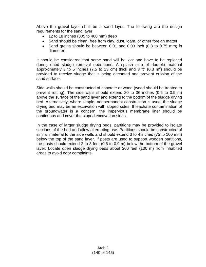
Above the gravel layer shall be a sand layer. The following are the design requirements for the sand layer:
• 12 to 18 inches (305 to 460 mm) deep • Sand should be clean, free from clay, dust, loam, or other foreign matter • Sand grains should be between 0.01 and 0.03 inch (0.3 to 0.75 mm) in
diameter.
It should be considered that some sand will be lost and have to be replaced during dried sludge removal operations. A splash slab of durable material approximately 3 to 5 inches (7.5 to 13 cm) thick and 3 ft2 (0.3 m2) should be provided to receive sludge that is being decanted and prevent erosion of the sand surface. Side walls should be constructed of concrete or wood (wood should be treated to prevent rotting). The side walls should extend 20 to 36 inches (0.5 to 0.9 m) above the surface of the sand layer and extend to the bottom of the sludge drying bed. Alternatively, where simple, nonpermanent construction is used, the sludge drying bed may be an excavation with sloped sides. If leachate contamination of the groundwater is a concern, the impervious membrane liner should be continuous and cover the sloped excavation sides. In the case of larger sludge drying beds, partitions may be provided to isolate sections of the bed and allow alternating use. Partitions should be constructed of similar material to the side walls and should extend 3 to 4 inches (75 to 100 mm) below the top of the sand layer. If posts are used to support wooden partitions, the posts should extend 2 to 3 feet (0.6 to 0.9 m) below the bottom of the gravel layer. Locate open sludge drying beds about 300 feet (100 m) from inhabited areas to avoid odor complaints.
Atch 1
(140 of 145)
Figure A1.54. Excavated Sludge Drying Bed
A1.8.7.3. Sludge Drying Bed Operation and Maintenance
Fresh sludge is typically pathogenic and should be handled with care. Sludge should be pumped to the drying bed directly or via a pump truck. Sludge is generally applied in 3- to 12-inch (7 to 30 cm) layers. If the sludge tends to separate from the liquid, the clear liquid at the top may be drawn off. The sludge should be allowed to dry until the desired solids concentration is achieved. This will vary by climate and location; a moisture content of 60 percent can be achieved in 10 to 15 days under favorable conditions. The drying process can be accelerated by breaking up the dry, crusty layer at the top with a shovel or auger. Sludge will continue to dry during periods of freeze-thaw cycling. Sludge should be dry to moist and crumbly (not wet) when removed. Dried sludge can be removed with mechanical equipment or shovels and wheelbarrows. If trucks are used for removal, provisions should be made to allow them to drive alongside the beds. Trucks should not be driven on the beds. Any sand removed during dried sludge removal should be replaced and sludge may be reapplied.
A1.8.7.4. Sludge Drying Bed Design Calculation
Sludge drying beds are sized based on the number of individuals they will serve. Generally, it is assumed that 1 to 1.5 ft2 of drying area is required per person (see Metcalf & Eddy, Wastewater Engineering, Treatment and Reuse).
Atch 1
(141 of 145)
Example: Size a sludge drying bed for a facility with a wastewater treatment system sized for 3000 gal/day.
Solution: Using 40 gpd/person from Table A1.3, 3,000 gal/day ÷ 40 gal/person/day = 75 people
75 people x 1.5 ft2/person = 113 ft2 The sludge drying bed should be sized as follows: Use 120 ft2 or 10 feet x 12 feet for ease of construction or two 6-foot x 10-foot beds for ease of access.
A1.9. DECOMMISSIONING TEMPORARY SANITARY FACILITIES UFC 1-201-01, Facilities In Support of Military Operations, has guidelines to transition to a permanent treatment facility. At the time the decision has been made to transition to permanent facilities or closing operations, the removal of discontinued temporary facilities is required. Eliminating and properly decommissioning such facilities will reduce the risk of exposure to the environment and personnel. Buried infrastructure to be abandoned in-place should be identified and mapped to avoid exposure and conflict with future construction. Lagoons are not easily closed and it is recommended to use commercial lagoon systems or other wastewater treatment alternative to allow sites to return to the pre-deployment state. A1.10. DESIGN REVIEW, CONSTRUCTION INSPECTION, AND MONITORING A successful project depends on proper design, construction, and operation to ensure long-term service and reliability of the wastewater treatment system installed at a deployed location. Review and documentation of these project elements is important for ongoing maintenance as well as for future reference if a problem or changed condition need to be addressed. The checklist outlines provided herein are intended as a guide and should be modified as needed for a specific project.
Atch 1
(142 of 145)

A1.10.1. DESIGN REVIEW GUIDE
At a minimum, the following steps should be taken when conducting a design review. Completion of the review items below are critical to ensuring the design will be capable of handling the flow. Completing a proper design review will help to minimize confusion during the construction phase.
Review Soil Testing Records
1. Soil classification 2. Ground water depth 3. High ground water level
Review Percolation Test Results 1. Percolation rate 2. Hydraulic loading recommendation
Review Wastewater Characteristics
1. BOD 2. TSS 3. Temperature
Check Calculations
1. Verify ADF calculation 2. Verify sizing of unit processes 3. Verify loading rates 4. Verify assumptions made
Check Site Plan Layout
1. Check required offsets 2. Check for conflicts with existing structures 3. Check for conflicts with pending construction projects 4. Check that dimensions shown match calculations 5. Check correct scale is indicated
Verify Record Keeping Of Project
1. Project file has been established 2. Design calculations 3. Assumptions for design 4. Copy of design
Atch 1
(143 of 145)
A1.10.2. CONSTRUCTION INSPECTION GUIDE
After the design has been completed it is ready for construction. The primary purpose of the construction inspection is to ensure the final product was built in accordance with the design. Construction inspectors should maintain a field book and daily log of construction activities. The following items are the minimum that should be checked and/or verified by the construction inspector to ensure they are in compliance with the design.
Materials
1. Check dimensions 2. Verify materials of construction 3. Verify quantity 4. Verify items are free from defects
Design Integrity
1. Verify dimensions shown on drawing match field dimensions 2. Check that location shown on drawing matches field locations 3. Take swing ties for record purposes 4. Check that piping slope on drawing matches slope in field 5. Verify elevations shown on drawings match field elevations
Testing
1. Establish field testing schedule 2. Maintain record of field tests 3. Observe field tests of all equipment and processes 4. Compare field test results to design criteria 5. Ensure contractor addresses any piece of equipment or process that does not
pass the field test
Design Records 1. Maintain field book 2. Maintain daily log book 3. Maintain redline set of drawings 4. Take photographs of construction progress
Atch 1
(144 of 145)
A1.10.3. GUIDE TO OPERATIONS MONITORING
Once the construction has been completed, the facility will go into operation. Daily monitoring of the various processes is essential to ensuring their proper long-term function. Monitoring alerts the operators to potential or existing problems if proper records are maintained. The following is a guide to developing a comprehensive monitoring program.
Conduct Daily Inspections
1. Take a site walk 2. Take site photographs periodically 3. Note any changes in conditions 4. Odors 5. Color 6. Changes in soil characteristics 7. Puddling or ponding 8. Photograph changes 9. Review maintenance log 10. Report any changes to your supervisor
Record Keeping
1. Establish a maintenance log 2. Repairs 3. Cleanings 4. Other problems 5. Establish a sampling log 6. Record known flow rates 7. Record pump run time 8. Record known exterior changes (such as significant increase in site
population or unusual amounts of precipitation) as they may have an impact on proper functionality
Sampling 1. Set up a sampling schedule per guidelines 2. Record sample results in log book 3. Take samples per established sampling schedule 4. Measure flow 5. Note any deviations from previous samples 6. Report deviations to supervisor
Maintenance
1. Establish a routine maintenance schedule 2. Cleaning 3. Lubrication 4. Replaceable parts 5. Record routine maintenance in maintenance log
Atch 1
(145 of 145)

ACRONYMS AND GLOSSARY ADF—average daily flow AFCEC/CO—Air Force Civil Engineer Center, Operations Directorate AFCEC/COSC—Air Force Civil Engineer Center, Operations Directorate, Engineer Support Division, Civil Branch AFCEC/CX—Air Force Civil Engineer Center, Readiness Directorate AFI—Air Force instruction AFPAM—Air Force pamphlet AFPD—Air Force policy directive ASTM—American Society for Testing and Materials BNR—Biological Nutrient Removal BOD—biochemical oxygen demand C—Celsius cfs—cubic feet per second cfu—colony-forming unit Cl2—chlorine cm/day—centimeters per day cm—centimeter COD—chemical oxygen demand CONUS—continental United States CW—constructed wetlands CY—cubic yard D-box—distribution box DOD—Department of Defense DO—dissolved oxygen E.O.—Executive Order ENR—Engineering News-Record EPA—Environmental Protection Agency ETL—Engineering Technical Letter F—Fahrenheit fps—feet per second ft2—square foot ft3—cubic foot ft—foot FWS—free water surface gal—gallons gpcd—gallons per capita per day gpd/sf—gallons per day per square foot gpd—gallons per day gpi—gallons per inch gpm—gallons per minute GW—groundwater ha/day—hectare per day ha—hectare HDPE—high-density polyethylene
Atch 2
(1 of 12)
HLR—hydraulic loading rate IA—international agreement ID—inside diameter in—inch ISRIC—International Soil Reference and Information Center kg/cm—kilogram per centimeter kg/ha/d—kilograms per hectare per day kg—kilogram lb/ac/d—pounds per acre per day lb—pound LF—lineal feet L—liter log—logarithmic Lpcd—liters per capita per day Lpd—liters per day m/s—meters per second m2—square meter m3/s—cubic meters per second MBR—membrane biological reactor mg/L—milligrams per liter MH—manhole mL—milliliter MLSS—mixed liquor suspended solids m—meter mm—millimeter MPN—most probable number N/A—not applicable N—nitrogen NRCS— Natural Resources Conservation Service, US Department of Agriculture O&M—operation and maintenance o.c.—on center OEBGD—Overseas Environmental Baseline Guidance Document OPORD—operation order perc—percolation PF—peaking factor pH—measure of the activity of the (solvated) hydrogen ion PO—purchase order P—phosphorus PVC—polyvinyl chloride rpm—revolutions per minute RR—recirculation ratio RSF—recirculating sand filter s/d—seconds per day SAS—subsurface adsorption system SDR—standard dimension ratio SF—subsurface flow
Atch 2
(2 of 12)
SOFA—status of forces agreement SW—surface water SWIS—subsurface wastewater infiltration system SY—square yard TDH—total dynamic head TDS—total dissolved solids TN—total nitrogen TSS—total suspended solids TS—total solids U.S.—United States UFC—Unified Facilities Criteria USDA—United States Department of Agriculture UV—ultraviolet light WHO—World Health Organization WWTF—wastewater treatment facility WW—wastewater Absorption: The process by which one substance is taken into and included within another substance, such as the absorption of water by soil or nutrients by plants. Activated Sludge Process: A biological wastewater treatment process in which active sludge is agitated and aerated with incoming wastewater to promote treatment. The activated sludge is subsequently separated from the treated wastewater (mixed liquor) by settling, and most is recycled to the process. Adsorption: The increased concentration of molecules or ions at a surface, including exchangeable cations and anions on soil particles. The adherence of a dissolved solid to the surface of a solid. Advanced Wastewater Treatment: Treatment beyond the secondary or biological stage of treatment. It includes removing nutrients such as phosphorus and nitrogen and a high percentage of suspended solids. It is also often called tertiary treatment. Aeration: The process of exposing wastewater to circulating air to assist biological treatment. Aerobic: Refers to life or processes that require the presence of free elemental oxygen. Typically the dissolved oxygen is greater than 1.0 mg/L. Aerobic Treatment Unit (ATU): A mechanical treatment unit that provides secondary wastewater treatment by mixing air (oxygen) and aerobic and facultative bacteria with the wastewater. ATUs typically use a suspended growth treatment process (similar to activated sludge extended aeration) or a fixed film treatment process (similar to trickling filter).
Atch 2
(3 of 12)
Ammonia Nitrogen: Ammonia or ammonium form of nitrogen in raw sewage that is converted in the nitrification process. The majority of the organic nitrogen contained in raw sewage is converted to ammonia and/or ammonium while travelling through the sewer pipe. Anaerobic: Refers to life or processes that require the absence of free elemental oxygen. Anoxic: Refers to processes that require low oxygen concentrations (less than 0.5 mg/L) such as the denitrification process where the bacteria utilize the oxygen in the nitrate molecule (NO3) to complete the reaction and thus release nitrogen gas. Assimilation: Aerobic microbes consume the nutrients in the wastewater. Bacteria: Bacteria are single-cell microscopic organisms that grow in nearly every environment. In wastewater treatment, they can perform a variety of biological treatment processes. Biochemical Oxygen Demand (BOD): BOD is the measure of the amount of oxygen consumed in biological processes that break down organic matter in water. Higher BOD values indicate a greater degree of pollution. Biomat: The layer of biological growth and inorganic residue under a leaching field that develops at the wastewater-soil interface and extends up to about 1 inch into the soil matrix. The biomat controls the rate at which wastewater moves through the infiltrative zones in soils or leaching field. Biosolids: Biosolids are the primarily organic solid product of wastewater treatment processes and can be beneficially recycled or appropriately disposed of at a landfill or incinerator. Chemical Oxygen Demand (COD): A measure of oxygen use equivalent to the portion of organic matter susceptible to oxidation by a strong chemical oxidizing agent. Chemical Sorption: Contaminants stick to the surface of the sand and to the biological growth on the sand surface. Chlorine Residual: The total amount of chlorine (combined and free available chlorine) remaining in water, sewage, or industrial wastes at the end of a specified contact period following disinfection. Clay: A textural class of soils consisting of particles less than 0.002 mm in diameter. Coliform Bacteria: A group of bacteria predominantly inhabiting the intestines of humans or other warm-blooded animals, but also occasionally found elsewhere. Used as an indicator of human fecal contamination.
Atch 2
(4 of 12)
Composite Sample: Consists of a collection of numerous individual discrete samples taken at regular intervals over a period of time, typically 24 hours. The combined sample represents an average of the measured characteristics over that period. Composite samples are used to measure influent and effluent characteristics for a wastewater treatment facility and compared to determine effectiveness. Constructed Wetland: An aquatic treatment system consisting of one or more lined or unlined basins, some or all of which may be filled with a treatment medium and wastewater undergoing some combination of physical, chemical, and/or biological treatment and evaporation and evapotranspiration by means of macrophytes planted in the treatment medium. Contingency Location: A non-enduring location outside the United States that supports and sustains operations during named and unnamed contingencies or other operations as directed by appropriate authority and is categorized by mission life-cycle requirements as initial, temporary, or semi-permanent (see DODD 3000.10). Denitrification: The conversion of nitrate nitrogen molecules to nitrogen gas in an anoxic reactor. Deployment/Deployed Location: A non-enduring location that supports and sustains operations during named and unnamed contingencies or other operations as directed by appropriate authority. Digestion: The biological decomposition of organic matter in sludge, resulting in partial gasification, liquefaction, and mineralization. Disinfection: The process of destroying pathogenic and other microorganisms in wastewater, typically through application of chlorine compounds, UV light, iodine, ozone, and the like. Dissolved Oxygen (DO): The oxygen dissolved in water, wastewater, or other liquid, usually expressed in milligrams per liter (mg/L), parts per million (ppm), or percent of saturation. Dissolved Solids: The fraction of solids dissolved in water. Distribution Box (D-box): A watertight box where flow is equalized and distributed into multiple pipes. Often, septic tank effluent is piped to a distribution box for flow splitting into multiple areas of the leaching field. Dose: Application of wastewater volume over a period of time. Drain Field (also leaching field, absorption field): Shallow, covered excavation made in unsaturated soil into which pretreated wastewater is discharged through distribution
Atch 2
(5 of 12)
piping for application onto soil infiltration surfaces. The soil accepts, treats, and disperses wastewater as it percolates through the soil, ultimately discharging to groundwater. Effluent: Sewage, water, or other liquid, partially or completely treated or in its natural state, flowing out of a septic tank, subsurface wastewater infiltration system, aerobic treatment unit, or other treatment system or system component. Effluent Filter: A removable, cleanable device inserted into the outlet tee of the septic tank or dosing pump designed to trap solids that may clog the leaching system or other downstream treatment components. Effluent Screen: See Effluent Filter. Environmental sensitivity: The relative susceptibility to adverse impacts of a water resource or other environments that may receive wastewater discharges. Eutrophic: A term applied to water that has a concentration of nutrients that encourage plant or animal growth. In general, nitrogen and phosphorus compounds contribute to eutrophic conditions in coastal and inland fresh waters, respectively. Evapotranspiration: The combined loss of water from a given area and during a specified period of time by evaporation from the soil or water surface and by transpiration from plants. Facultative Bacteria: A type of bacteria that consumes oxygen dissolved in water (like aerobic bacteria) or by taking if off molecules in the water that are combined with oxygen such as a nitrate molecule (NO3). Filter Media: Material such as sand, stone, pellets, or other product used in a bed or tank that serves as a host for biological treatment as wastewater passes through. Filtration: Particles are physically strained from the wastewater passing through a medium such as a sand bed, soil, or other fixed material. Fixed-Film Wastewater Treatment System: A biological wastewater treatment process that employs a medium such as rock, plastic, wood, or other natural or synthetic solid material that supports biomass on its surface. Grab Sample: A sample volume of water taken to measure characteristics such as pH, BOD, and/or TSS at a specific point in time at the source taken. A grab sample is typically used as a check and is not as representative as a composite sample to determine process performance. Graywater: Wastewater drained from sinks, tubs, showers, dishwashers, clothes washers, and other non-toilet sources.
Atch 2
(6 of 12)
Hydraulic Conductivity: As applied to soils, the ability of the soil to transmit water in liquid form through pores. Hydraulic Loading Rate: Flow volume unit for application to a surface area, such as gallons per day per square foot. Influent: Water, wastewater, or other liquid flowing into a reservoir, basin, treatment plant, or treatment process. Infrastructure: The network of pipes, tanks and equipment above and below ground that transmit, process, treat, and discharge treated wastewater. Laminar: Used to describe flat, sheet-like ground water flows that migrate laterally along the upper surface of a confining layer of soil or rock. Land Application: The treatment or disposal of wastewater or wastewater solids by spreading it on land under controlled conditions. Loading Factors: Concentration of specific wastewater pollutant characteristics such as BOD, TSS, and ammonia. Mass Loading Variation: Variations in the concentration of loading factors in the influent wastewater. Membranes: Soft, pliable sheets or layers used in filtration processes. Membrane Bioreactors: Combined activated sludge treatment processes and membrane filtration equipment to separate liquids and solids. Microorganisms: Microscopic organisms, either plant or animal, invisible or barely visible to the naked eye; for example, bacteria, fungi, protozoa, and viruses. Mineralization: The conversion of an element from an organic form to an inorganic state as a result of microbial decomposition. Most Probable Number (MPN): Typically used in reference to a fecal colony count for 100 mL effluent sample. Mottling: Spots or blotches of different colors or shades of color interspersed with the dominant soil color caused in part by exposure to alternating unsaturated and saturated conditions. Nitrification: The biochemical oxidation of ammonia/ammonium to nitrate, typically achieved in an aerobic reactor. It is a two-step process whereby one type of bacteria
Atch 2
(7 of 12)
converts ammonia and ammonium to nitrite then another bacteria converts nitrite to nitrate. Nutrients: Elements or compounds, such as nitrogen, phosphorus, and potassium, that are necessary for plant growth. Onsite WWTF: Refers to wastewater managed and treated at the site generated vs. being discharged to a collection system and conveyed to a remote WWTF. Operation and Maintenance (O&M): The organized procedure for keeping the equipment or plant in such a condition that it is able to continually and reliably perform its intended function. Operating Permit: A renewable and revocable permit to operate and maintain a treatment system in compliance with specific operational or performance requirements. Organic Nitrogen: Nitrogen combined in organic molecules such as proteins and amino acids. Organic Soil: A soil that contains a high percentage (more than 15 to 20 percent) of organic matter throughout the soil column. Particle Size: The effective diameter of a particle, usually measured by sedimentation or sieving. Particle Size Distribution: The amounts of the various soil size fractions in a soil sample, typically expressed as weight percentage. Pathogenic: Causing disease; commonly applied to microorganisms that cause infectious diseases. Peaking Factor: Adjustments to flow or loading that consider periods of higher concentration. Percolation: The flow or trickling of a liquid downward through a contact or filtering medium. Perc Test: The procedure for measuring the soil percolation rate at a site. Performance Requirement: Any requirement established by the regulatory authority to ensure future compliance with public health and environmental goals. Permeability: The ability of a porous medium such as soil to transmit fluids or gases.
Atch 2
(8 of 12)
pH: A term used to describe the concentration of hydrogen ion in an aqueous solution on a logarithmic scale with numbers less than 7 being acidic, numbers greater than 7 being basic, and 7 being neutral; relative to acidity. Physical Boundaries: Points in the flow of wastewater through the treatment system where treatment processes change. A physical boundary can be at the intersection of unit processes or between saturated and unsaturated soil zones. A physical boundary may also be a performance boundary if so designated by the regulatory authority. Pretreatment System: Any technology or combination of technologies that precedes discharge to a subsurface wastewater infiltration system or other final treatment unit or process before final dissemination into the receiving environment. Receiving Site: A river, lake, ocean, or groundwater aquifer into which wastewater or treated effluent is discharged. Regulatory Authority (RA): The level of government that establishes and enforces codes related to the permitting, design, placement, installation, operation, maintenance, monitoring, and performance of wastewater treatment systems. Residuals (Sludge): The solids generated and retained during the treatment of wastewater, including sludge, scum, and residuals from grease traps, septic tanks, aerobic treatment units, and other components of a treatment system. Sand Filter: A packed-bed filter of sand or other granular materials used to provide advanced secondary treatment of settled wastewater or septic tank effluent. Sand/media filters consist of a lined (e.g., impervious PVC liner on sand bedding) excavation or structure filled with uniform washed sand that is placed over an underdrain system. The wastewater is dosed onto the surface of the sand through a distribution network and allowed to percolate through the sand to the underdrain system, which collects the filter effluent for further processing or discharge. Scum: Grease, fats, and material that floats to the top of the septic tank. Septage: The mixture of solid wastes, scum, sludge, and liquids pumped from within septic tanks, grease traps, pump chambers, holding tanks, and other process components. Septic Tank: A tank that receives and partially treats raw wastewater. Settleable solids settle to the bottom to form a sludge layer. Grease and other light materials float to the top to form a scum layer. The removed solids are stored in the tank, where they undergo liquefaction in which organic solids are partially broken down into dissolved fatty acids and gases. Gases generated during liquefaction of the solids are normally vented through the building’s plumbing stack vent.
Atch 2
(9 of 12)

Sequencing Batch Reactor: A sequential suspended-growth (activated sludge) process in which all major steps occur in the same tank in sequential order. Sequencing batch reactors include intermittent-flow batch systems and continuous-flow systems. Settleable Solids: Matter in wastewater that will settle out of suspension by gravity. Sewage: Any urine, feces, and the water carrying human wastes, including kitchen, bath, and laundry wastes from residences, buildings, industrial establishments, or other places. Sewage is generally synonymous with wastewater. Sewer: Pipe system that carries sewage or wastewater. Silt: A textural class of soils consisting of particles between 0.05 and 0.002 millimeter in diameter. Sludge: Heavy solids, grit, and sand that fall to the bottom of a septic tank or wastewater process tank. Soil Horizon: A layer of soil or soil material approximately parallel to the land surface and different from adjacent layers in physical, chemical, and biological properties or characteristics such as color, structure, texture, consistence, and pH. Soil Map: A map showing the distribution of soil types or other soil mapping units in relation to prominent physical features. Soil Morphology: The physical properties of a soil as exhibited by the arrangement of the horizons in the profile and by the texture, structure, consistence, and porosity of each horizon. Soil Structure: The arrangement of individual soil particles that are characterized and classified on the basis of size, shape, and degree of distinctness. Soil Survey: The systematic examination, description, classification, and mapping of soils in an area. Soil Texture: The relative proportions of the various soil separates (e.g., silt, clay, sand) in a soil. Soil Water: A general term emphasizing the physical rather than the chemical properties and behavior of the soil solution. Stratification: The separation of liquid into layers; heavier solids settle to the bottom and lighter material (scum) float at the surface, such as in a septic tank, resulting in a clear mid-layer. Subsoil: In general, that part of the soil below the depth of plowing.
Atch 2
(10 of 12)
Subsurface Absorption System (SAS): Also known as leaching field: An underground system for dispersing and further treating pretreated wastewater. The SAS includes the distribution piping/units, any media installed around or below the distribution components, the biomat at the wastewater-soil interface, and the unsaturated soil below. Suspended Solids: Solid pollutants that either float on the surface of or are suspended in wastewater primarily due to their small size. They can also be called total suspended solids (TSS). Topsoil: The layer of soil containing organic material. Total Kjeldahl Nitrogen (TKN): The combination of organic nitrogen and ammonia in wastewater. The Kjeldahl lab test includes digestion to determine the organically bound nitrogen and ammonia/ammonium that is much higher in untreated wastewater. Organic nitrogen must be converted to ammonia/ammonium for nitrification to occur. Treatment System: Any technology or combination of technologies (treatment trains or unit processes) that process and discharge treated wastewater to surface waters, ground water, or the atmosphere. Unsaturated Flow: Movement of water in a soil that is not filled to capacity with water. United States: The several states, the District of Columbia, the Commonwealths of Puerto Rico and the Northern Mariana Islands, American Samoa, Guam, Midway and Wake Islands, the United States Virgin Islands, any other territory or possession of the United States, and associated navigable waters, contiguous zones, and ocean waters of which the natural resources are under the exclusive management authority of the United States (see DODD 3000.10). UV Disinfection: Disinfection achieved by passing water through a UV reactor that emits radiation with a specific wavelength to destroy bacteria in the water. Vegetated Submerged Bed: A constructed wetland wastewater treatment unit characterized by anaerobic horizontal subsurface flow through a fixed-film medium that has a growth of aquatic plants on the surface. Wastewater: Used water from a community or facility that contains dissolved or suspended matter; also known as sewage. Wastewater Treatment Facilities: Refers to collection, transmission and treatment facilities that handle wastewater.
Atch 2
(11 of 12)
Water Quality-Based Performance Requirement: A specific, measurable, and enforceable standard that establishes limits for pollutant concentrations or mass loads in treated wastewater discharged to ground water or surface waters. Water Quality Criteria: A set of enforceable requirements under the Clean Water Act that establish measurable limits for specific pollutants based on the designated use(s) of the receiving water body. Water quality criteria can be expressed as numeric limits (e.g., pollutant concentrations or mass loads) or narrative descriptions of desired conditions (e.g., no visible scum, sludge, sheens, or odors). Water Quality Standards: A set of enforceable requirements under the Clean Water Act that include classification of receiving waters in accordance with their federal or state designated use(s), use-based water quality criteria that establish measurable limits for specific pollutants, and anti-degradation provisions to ensure that water quality is maintained or improved. Water Table: The level in saturated soil at which the hydraulic pressure is zero, i.e., top of saturated soil.
Atch 2
(12 of 12)

REFERENCES A3.1. U.S./Federal.
• Clean Water Act (Water Pollution Control Act) Public Law (P.L.) 845 • EPA 625/1-80-012, Design Manual: On-Site Wastewater Treatment Systems,
October 1980 • EPA 832-B-03-001, Guidelines for Management of Onsite/Decentralized
Wastewater Systems, 2003 • EPA 832-F-00-073, Collection Systems Technology Fact Sheet, Sewers, Lift
Station, September 2000 • EPA Constructed Wetlands for Wastewater Treatment and Wildlife Habitat,
available at http://water.epa.gov/type/wetlands/constructed/index.cfm • EPA Onsite Treatment Systems Technology Fact Sheet 11 (TFS-11),
Recirculating Sand/Media Filters • EPA Onsite Wastewater Treatment Systems Technology Fact Sheet 10 (TFS-
10), Intermittent Sand/Media Filters • EPA-625/1-81-013, Land Treatment of Municipal Wastewaters Process Design
Manual, 1981 • EPA-625/1-83-015, Design Manual for Municipal Wastewater Stabilization
Ponds, October 1983 • EPA-625/R-00/008, Onsite Wastewater Treatment Systems Manual, February
2002 • International Soil Reference and Information Center (ISRIC), World Soil
Information, http://www.isric.org/ • Massachusetts Department of Environmental Protection, 310 CMR 15.000,
Standard Requirements for the Siting, Construction, Inspection, Upgrade and Expansion of On-Site Sewage Treatment And Disposal Systems and for the Transport and Disposal of Septage, http://www.mass.gov/dep/service/regulations/310cmr15.pdf
• Safe Drinking Water Act, Public Law (P.L.) 93-523 A3.2. Air Force.
• AFI 10-210, Prime Base Engineer Emergency Force (BEEF) Program, 6 September 2012, http://www.e-publishing.af.mil/
• AFI 10-211, Civil Engineer Contingency Response Planning, 16 November 2011, http://www.e-publishing.af.mil/
• AFI 32-1023, Designing and Constructing Military Construction Projects, 21 April 2010, http://www.e-publishing.af.mil/
• AFI 32-1067, Water Systems, 25 March 1994, http://www.e-publishing.af.mil/ • AFI 91-203, Air Force Consolidated Occupational Safety Instruction, 15 June
2012, http://www.e-publishing.af.mil/ • AFH 10-222, Volume 4, Environmental Considerations for Overseas Contingency
Operations, 1 September 2012, http://www.e-publishing.af.mil/ • AFPAM 10-219V5, Bare Base Conceptual Planning Guide, 1 June
1996, http://www.e-publishing.af.mil/
Atch 3 (1 of 3)
• AFPAM 10-219V7, Expedient Methods, 9 June 2008, http://www.e-publishing.af.mil/
• AFPD 10-2, Readiness, 6 November 2012, http://www.e-publishing.af.mil/ • AFPD 32-10, Installations and Facilities, 4 March 2010, http://www.e-
publishing.af.mil/ • Air Force Sustainable Design and Development (SSD) policy memorandum, 31
July 2007, http://www.afcee.af.mil/shared/media/document/AFD-080609-022.pdf • ETL 08-10, Alternative Water Sources – Use of Non-Potable Water, 10 July
2008, http://www.wbdg.org/ccb/browse_cat.php?o=33&c=125 A3.3. Department of Defense. • DOD 4715.05-G, Overseas Environmental Baseline Guidance Document, 1 May
2007, http://www.dtic.mil/whs/directives/corres/pdf/471505g.pdf • DODD 3000.10, Contingency Basing Outside the United States, 10 January
2013, http://www.dtic.mil/whs/directives/corres/pdf/300010p.pdf • DODI 4715.5, Management of Environmental Compliance at Overseas
Installations, 22 April 1996, http://www.dtic.mil/whs/directives/corres/pdf/471505p.pdf
• UFC 1-201-01, Facilities In Support of Military Operations, http://www.wbdg.org/ccb/browse_cat.php?o=29&c=4
• UFC 3-240-03N, Wastewater Treatment Systems Augmenting Handbook Operation and Maintenance, 16 January 2004, http://www.wbdg.org/ccb/browse_cat.php?o=29&c=4
• UFC 3-230-02, O&M: Water Supply Systems, 10 July 2001, http://www.wbdg.org/ccb/browse_cat.php?o=29&c=4
• UFC 3-420-01, Plumbing Systems, 25 October 2004, http://www.wbdg.org/ccb/browse_cat.php?o=29&c=4
• UFC 3-220-01, Geotechnical Engineering, 1 November 2012, http://www.wbdg.org/ccb/browse_cat.php?o=29&c=4
• UFC 3-240-02, Domestic Wastewater Treatment, 1 November 2012, http://www.wbdg.org/ccb/browse_cat.php?o=29&c=4
• U.S. Army Public Health Command Technical Information Paper #32-001-0904, Field Wastewater Management in Desert Environments, http://phc.amedd.army.mil/PHC%20Resource%20Library/TIP32_001_0904.pdf
A3.4. Trade Organizations. • ASTM A184, Standard Specification for Welded Deformed Steel Bar Mats for
Concrete Reinforcement, http://www.astm.org/ • ASTM A615, Standard Specification for Deformed and Plain Carbon-Steel Bars
for Concrete Reinforcement, http://www.astm.org/ • ASTM C478, Standard Specification for Precast Reinforced Concrete Manhole
Sections, http://www.astm.org/ • ASTM D3034, Standard Specification for Type PSM Poly(Vinyl Chloride) (PVC)
Sewer Pipe and Fittings, http://www.astm.org/
Atch 3 (2 of 3)
• ASTM D5879, Standard Practice for Surface Site Characterization for Onsite Septic Systems, http://www.astm.org/
• ASTM D5921, Standard Practice for Subsurface Site Characterization of Test Pits for Onsite Septic Systems, http://www.astm.org/
• Black, C.A., ed. 1965. Methods of Soil Analysis, Part 1: Physical and Microbiological Properties, Including Statistical Measurement and Sampling, American Society of Agronomy
• Engineering News-Record (ENR) Construction Cost Index (May 2012), http://enr.construction.com/economics/
• International Code Council, International Private Sewage Disposal Code, http://publicecodes.cyberregs.com/icod/isc/2012/index.htm
• International Plumbing Code (IPC), published by International Code Council, 5203 Leesburg Pike Suite 708, Falls Church, VA, 22041-3401
• National Decentralized Wastewater Treatment Systems, http://www.ndwrcdp.org • National Small Flows Clearinghouse, http://www.nesc.wvu.edu/wastewater.cfm • New England Interstate Water Pollution Control Commission (NEIWPCC), TR-
16, Guides for the Design of Wastewater Treatment Works, http://www.neiwpcc.org/tr16guides.asp
• The Great Lakes - Upper Mississippi River Board of State and Provincial Public Health and Environmental Managers, Recommended Standards for Wastewater Facilities, http://10statesstandards.com/wastewaterstandards.html
• Uniform Plumbing Code (UPC), International Association of Plumbing and Mechanical Officials, 2001 Walnut Drive South, Walnut, CA 91789-2825
• Water Environment Federation (WEF) / American Society of Civil Engineers (ASCE) Joint Task Force 1992, Manuals of Practice (MOP) 76; WEF Manual of Practice No. 8, Design of Municipal Wastewater Treatment Plants, http://www.asce.org/Product.aspx?id=2147485721
A3.5. Industry/Institutions. • Clark, Viessman & Hammer, Water Supply and Pollution Control, 3rd Edition,
Harper & Row Publishers, NY • Kerri, K.D., and J. Brady, Small Wastewater System Operation and Maintenance,
Volume 1, 1997, California State University, Sacramento, CA • Metcalf & Eddy, Tchobanoglous, G., F. Burten, H. Stensel, Wastewater
Engineering, Treatment and Reuse, 3rd Edition, McGraw Hill, NY, 2003 • University of Rhode Island (URI) Cooperative Extension, Water Quality
Program, http://www.uri.edu/ce/wq
Atch 3 (3 of 3)
DISTRIBUTION LIST
DEPARTMENT OF DEFENSE Defense Commissary Agency (1) AAFES (1) Design and Construction Division ATTN: RE-C 2250 Foulois St., Suite 2 PO Box 660202 Lackland AFB, TX 78236 Dallas, TX 75266-0202 SPECIAL INTEREST ORGANIZATIONS Information Handling Services (1) Construction Criteria Base (1) 15 Inverness Way East National Institute of Bldg Sciences Englewood, CO 80150 Washington, DC 2000
Atch 4 (1 of 1)