Embed Size (px)
Citation preview

CUT-AWAY OPERATOR MANUAL
CHALLENGER/CRUSADER SERIES
DEFENDER SERIES
CHAMPION BUS, INC.
Thor Industries Commercial Bus Division 8/18/10
JP AG

FORD E350/E450 MODELS:
CR210, CH210, CH230 CH250, AM230, AM250
FORD F550 MODELS:
DF250, DF270, DF290, DF310, DF330
CHEVY 610 MODELS:
CR210, CH230, AC210, AC230, AC250
CHEVY 560 MODELS:
CH250, CH270, DF280, DF310, DF330, DF350, DF380, CC280, CC310, CC330, CC350, CC380, AM250, AM270, AM280, AM310,
AM330, AM350, AM380
INTERNATIONAL 3200 MODELS:
DF270, DF290, DF310, DF330, DF350, DF380, AM310, AM330, AM350, AM380, HC270, HC290, HC310, HC330, HC350, HC380
FREIGHTLINER M2 MODELS:
DF270, DF290, DF310, DF330, DF350, DF380, AM310, AM330, AM350, AM380
CHAMPION GENERA L COACH BUS, INC. AMERICA, INC.
Thor Industries Commercial Bus Division Thor Industries Commercial Bus Division

OPERATOR INFORMATION 2 DRUNK DRIVING 2 SAFETY EQUIPMENT 4 REPORTING SAFETY DEFECTS 8 VEHICLE SYSTEMS SAFETY CHECKS 9 PASSENGER SEATING 13 WEIGHTS AND LOADING 14 CHAMPION BUS, INC SERIAL NUMBER 15 BODY CONTROL SWITCHES 16 CHAMPION BUS ELECTRICAL PANEL 17 PARA TRANSIT LIFT OPERATION 18 18 PASSENGER HEATING SYSTEM 19 REAR CARGO STORAGE 20 OPEN-SHELF STORAGE 20 OVERHEAD STORAGE 20 AIR CONDITIONING 21 GENERAL WINDOW INFORMATION 22 DRIVER’S SEATING 23 PASSENGER SEATING ADJUSTMENTS 23 IN CASE OF EMERGENCY 24 PRETRIP INSPECTION 33 OPERATING INSTRUCTIONS 52 DAILY CHECKLISTS 57

Congratulations on your new Champion Bus Inc. Bus. If this is your
first, let me extend a warm welcome to the Champion Bus family. If you are
one of the many Americans and/or Canadians for whom Champion Bus
ownership has become a tradition, we believe that your new Champion Bus
will surpass your high expectations for a motor coach. It’s no exaggeration to
say that your new Champion Bus represents major improvements in design
and construction since the company first began making buses.
Please take a few minutes to acquaint yourself with your new coach.
In these manuals, not only Champion Bus’s, but Chevy’s, FORD’s, Ricon’s
or Braun’s, and others you will learn a great deal about your new vehicle’s
standard and optional equipment.
If you have additional questions, please don’t hesitate to call your
Champion Bus, Inc. Dealer or our Customer Service Department here at
Champion Bus in Michigan at 800-331-5761 X562.
Please count on us to deliver the unparalleled support you should
expect as Champion Bus, Inc. owner.
Sincerely yours,
John Resnik
President
Page 1

OPERATOR INFORMATION
THIS MANUAL SHOULD BE TREATED AS A PERMANENT PART OF THIS BUS. IT SHOULD STAY WITH THE VEHICLE UPON SALE OR TRANSFER TO A NEW OWN- ER, IN ORDER TO PROVIDE SUBSEQUENT OWNERS WITH IMPORTANT SAFETY, MAINTENANCE, AND OPERATION INFORMATION.
This manual was prepared to acquaint the driver / owner with its operation and function. This manual does not attempt to teach driving skills, rules of the road, or familiarity with local, state, or regional laws and regulations applicable to the operation of this vehicle on public highways. Also provided with this vehicle will be the OEM Operator’s Manual and additional infor- mational manuals from other special equipment companies. Refer to these manuals for chassis and or optional equipment related components.
IMPORTANT This operator Manual describes the use of standard and optional equipment provided on this vehicle at the time of original sale. Subsequent addition of new operating equipment or options by future owners of this vehicle or modifications to existing equipment, may affect the operating instructions as described herein. It is the responsibility of the operating entity to provide their operators with all pertinent and necessary instruction and information under these circumstances.
When it comes to service, keep in mind that your dealer knows your vehicle the best and is interested in your complete satisfaction.
Knowledge of the features of this vehicle and routine practice of recom- mended service and maintenance procedures is preemptive to passenger safety and comfort. Your ability as an operator depends on your awareness of the capabilities and limitations of this vehicle. You should become fully acquainted with all of the information provided within this manual in order to provide yourself and your passengers the safest and most efficient means of bus transport. Many people read their operator’s manual from beginning to end when they first receive their new vehicle. This will help you learn about the features and controls for the vehicle. In this manual, you will find that pictures and words work together to quickly explain things you will need to know.
DRUNK DRIVING Drinking and then driving is very dangerous. Your reflexes, perceptions, attentiveness, and judgement can be affected by even a small amount of alcohol. You can have serious - or even fatal- collision if you drive after drinking. Do not drink and drive.
Page 2

SYMBOLS
DANGER indicates a hazardous situation which, if not avoided, will result in death or serious injury.
WARNING indicates a hazardous situation which, if not avoided, could result in death or serious injury.
CAUTION, used with the safety alert symbol indicates a hazardous situation, which if not avoided, could result in minor or moderate injury.
NOTICE is used to address practices not related to personal injury. This applies to hazardous situations involving property damage only.
NOTE Important information regarding the maintenance of your vehicle.
SEAT BELTS AND PASSENGER RESTRAINTS Seat Belts should be worn by the driver, and any passenger seated in a seat that is equipped with restraints. Wheel-chaired passengers should be restrained with the supplied restraints provided.
NOT USING THE SAFETY RESTRAINTS PROVIDED COULD RESULT IN INJURY OR DEATH.
Page 3

EMERGENCY ESCAPE EXITS Roof Escape Hatch To open the roof top emergency escape hatch from the inside of the vehicle, follow the steps listed below:
1. Turn the handle clockwise to the ‘‘OPEN’’ position.
2. Push up on the hatch to open.
To close the hatch, pull down on the hatch on turn the handle to the ‘‘Latch’’ position to secure.
The roof escape hatch can also be used for ventilation, simply push up at the sides of the escape hatch and it will pop up for ventilation. Pull down and it will snap shut to close.
Page 4

EMERGENCY EXIT WINDOWS This vehicle is equipped with side windows that can be used as emer- gency escape exits. All emergency exit windows are marked with instructions for opening the windows in the event of an emergency. To use the windows) as an emergency escape exit, follow the procedure listed below.
1. Pull “DOWN” on both red handles on the latch and push “OUT” on the bottom of the window (reference the arrow in the picture). 2. To close the window, grasp window at handle and bottom center and pull inwards until the window is up against the frame. Latch the window into place by pulling “UP” on the red latch handle.
WHEN EXITING VIA AN EMERGENCYWINDOW, READ ALLTHE LABELS ANDWARNINGS APPLIED TO THE WINDOW, FAILURE TO PUSH OUT ON THE WINDOW CORRECTLY CAN CAUSE SERIOUS INJURY DUE TO BEING STRUCK BY THE DETACHED WINDOW AND ITS FRAME. IF THE WINDOW SHOULD UNHINGE DURING AN EMERGENCY EGRESS, MAKE SURE TO PUSH THE WINDOW OUTWARD AND AWAY FROM THE WINDOW OPENING AND CLEAR OF PERSONNEL NEAR THE WINDOW OPENING.
WHEN CLOSING THE PASSENGER WINDOW, DO NOT ALLOW THE ASSEMBLY TO SLAM SHUT. THIS WILL DAMAGE THE WINDOW AND POSSIBLY INJURE THE PERSON OR PERSONS INVOLVED.
Page 5

FIRE EXTINGUISHER
AVOID INHALING THE DR Y CHEMIC AL A GENT. THE A GENT C ONTAINED IN THIS EXTINGUISHER IS NOT TOXIC. BUT MAY CAUSE SKIN IRRITATION. IN CASE OF C O N T A C T , F L U S H A F F E C T E D A R E A W I T H C L E A N , C O O L W A - T E R . I F I R R I T A T I O N P E R S I S T S , C O N T A C T A P H Y S I C I A N IMMEDIATELY. CHEMICAL NAME OF AGENT IS PRINTED ON EXTINGUISHER LABEL.
Page 6

REFLECTIVE TRIANGLE WARNING KIT
BEFORE LEAVING DISABLED VEHICLE ALWAYS ACTIVATE THE VEHICLE’S EMERGENCY FLASHERS
Emergency Reflective Triangle Warning Kit On a straight highway Two (2) Lane:
1. On side of road, place one (1) Reflective Triangle 100 ft. In front of disabled vehicle (approx. 40 paces). 2. Then place another Reflective Triangle 100 ft. from rear of dis- abled vehicle (approx. 40 paces).
On a divided highway: 1. Place two (2) Reflective Triangles on side of road one at 100 ft. and the other
at 200 ft. from rear of disabled vehicle. (approx. 40 paces & 80 paces)
To assemble Triangle: 1.Raise two (2) arms of triangle and snap pin into slot. 2.Turn base 90° to it’s “Stop” position.
Page 7

REPORTING SAFETY DEFECTS
If you believe that your vehicle has a defect which could cause a crash or could cause injury or death, you should immediately inform the National Highway Traffic Safety Administration (NHTSA) in addition to notifying Champion Bus, Inc. If NHTSA receives similar complaints, it may open an investigation, and if it finds that a safety defect exists in a group of vehicles, it may order a recall and remedy campaign. However, NHTSA cannot be- come involved in individual problems between you, your dealer, or Cham- pion Bus, Inc. To contact NHTSA, you may either call the Vehicle Safety Hotline toll-free at 1-888-327-4236 (TTY: 1-800-424-9153); go to http:// www.safecar.gov; or write to: Administrator, NHTSA, 1200 New Jersey Avenue, S.E., Washington, DC 20590. You can also obtain other informa- tion about motor vehicle safety from http:www.safecar.gov.
Page 8

VEHICLE SYSTEMS SAFETY CHECKS This bus conforms to all Federal Motor Vehicle Safety Standards applicable at this time of manufacture, and in addition, incorporates other important features. However, even these safety features, con- tinued safe and dependable operation depends greatly on regular bus maintenance.
To retain the safety, dependability and emission control performance originally built into the vehicle, it is essential that it receive regular periodic inspection, maintenance and service parts replacement.
AS WITH ANY MACHINE, CARE SHOULD BE TAKEN WHEN PERFORMING ANY INSPECTION, MAINTENANCE, OR REPAIR SO AS TO MINIMIZE THE RISK OF INJURY. IMPROPER OR INCOMPLETE SERVICING CAN RESULT IN PERSONAL INJURY OR VEHICLE DAMAGE. SHOULD THERE BE ANY QUESTION ABOUT SERVICING THE VEHICLE, REFER REPAIRS TO QUALIFIED PERSONNEL.
NOTE: It is particularly important that any safety system which may have been compromised by collision damage be checked and repaired or replaced as necessary prior to putting the vehicle back into service.
Listed below are items that should be checked prior to taking the
FOR FURTHER DETAILS ON ENGINE AND TRANSMISSION SERVICE INTERVALS, REFER TO THE CHASSIS MANUAL.
Page 9

vehicle onto the road along with the pretrip inspection. Any deficien- cies or irregularities should immediately be brought to the attention of service personnel. Broken, incomplete, damaged or worn articles should be replaced / repaired after evaluation by qualified personnel.
Lap Belt – Check webbing, buckle, latch plate, retractor and attach- ing point for proper operation and for damage.
Windshield Wiper/Washer – Check operation of wipers as well as condition and function of wiper blades. Check amount and direction of fluid sprayed by washer during use.
Mirrors & Sun Visor – Check for proper operation and adjust as required.
Windshield Defroster – Check performance by moving the fan speed switch through the various blower settings. Note the amount of air directed against the windshield and the direction of air flow across the windshield.
Lights & Buzzers – Check all instrument panel warning lamps, and all interior and exterior lights for proper illumination. Any compo- nents found to be defective or inoperative should be repaired / re- placed.
Doors, Windows & Emergency Escapes – Check for positive open- ing, closing and latching operations. Check that window emergency release levers work properly and that windows open, close and latch properly. Check that all compartment and passenger doors are secure- ly closed by re-opening after each use. Also check for broken, miss- ing or loose parts that can prevent positive latching.
Wheel Alignment & Tire Balance – In addition to uneven or abnor- mal tire wear, the need for wheel alignment service may be indicated by a pull to the left or right while driving on a straight and level road. The need for wheel balancing is usually indicated by vibration of the steering wheel or seat while driving at normal highway speeds. Con- tact service personnel for repair if either condition is evident.
Page 10

Fluid Leaks – Check for fuel, water, oil or other fluid leaks by observing the surface beneath the bus after it has been parked for a period of time (water dripping from the air conditioning system is normal). If diesel fuel fumes are noticed at any time, the cause must be determined and immediately corrected because of the danger of fire.
Exhaust System – Be alert to any changes in the sound of the ex- haust system of the smell of exhaust fumes. This could indicate an exhaust leak requiring repair at the first available opportunity.
Seat Adjusters – Check that the seat adjuster engages securely by pushing forward and backward on the seat whenever adjustments have been made.
Steering – Be alert to any changes in steering action. The need for inspection or service is indicated if there is increased steering effort, excessive free play in the steering wheel or any unusual sounds when turning or parking.
Parking Brake – Check the parking brake by parking the bus on a slope and setting the brake. The vehicle should remain stopped while the brake is applied.
Brakes – Changes in braking action such as pulling to one side, increased pedal travel or unusual sounds when braking or between brake actuations should be reported and corrected immediately.
Page 11

NOTES:
Page 12

PASSENGER SEATING
Notes: See Seating Manual for cleaning material and service parts.
Page 13

WEIGHTS AND LOADING This vehicle is designed to provide satisfactory service throughout its lifetime if it is not loaded in excess of either the Gross Vehicle Weight Rating (GVWR) or the Gross Axle Weight Rating (GAWR). This cer- tification label shows the maximum allowable weight for the suspen- sion, shown as the Gross Axle Weight Rating (GAWR).
The Gross Vehicle Weight Rating (GVWR) is the maximum permis- sible weight of the vehicle, and takes into account the capabilities of the engine, transmission, suspension, axles, brakes and tires.
OVERLOADING THE BUS IN EXCESS OF THE POSTED WEIGHT LIMITS AND SPECIFICATIONS CAN RESULT IN COMPONENT FAILURE LEADING TO LOSS OF VEHICLE CONTROL, PERSONAL INJURY OR DEATH.
FAILURE OF A COMPONENT DUE TO OVERLOADING CONSTITUTES MISUSE. THE NEW VEHICLE WARRANTY DOES NOT APPLY TO ANY PART OF THE BUS THAT HAS BEEN SUBJECT TO MISUSE.
Page 14

CHAMPION BUS, INC. SERIAL NUMBER The CBI Serial Number is different from the Vehicle Identification Number (VIN). The CBI Serial Number is located on a plate on the driver’s door opening pillar. It is used by the manufacturer to identify the bus and it’s options. When contacting the dealer for service or for a warranty claim, be sure to provide the serial number for identification.
GAUGES, STEERING COLUMN, TACH, TRANSMISSION, PARKING BRAKE AND INSTRUMENTATION
Please refer to your OEM Operator’s Manual for any information on your vehicles gauges, steering column, tach, transmission, parking brake and instrumentation guide.
Your OEM Operator’s Manual is included in your vehicle package.
Page 15

BODY CONTROL SWITCHES DRIVER’S DOME LIGHT SWITCH T h e D R I V E R ’ S DOME LIGHT switch controls the dome light located above the driver.This switch is optional, standard
light switch.
INTERIOR LIGHT SWITCH The INTERIOR LIGHT switch controls the interior Light bar l i g h t s l o c a t e d i n the transition area between the roof and sidewalls on either side of the bus.
CENTER CEILING LIGHTS The CENTER CEILING L I G H T S s w i t c h controls the ceiling lights located in the center of the ceiling panel.
REAR HEATER SWITCH
T h e R E A R H E A T E R s w i t c h controls the rear h e a t e r l o c a t e d in the passanger compartment.
DRIVER’S DEFROST FAN SWITCH T h e D R I V E R ’ S DEFROST FAN switch controls the defrost fan located above the driver.
LIFT MASTER SWITCH The LIFT MASTER switch controls the the activation of the lift once all interlock conditions are met.
FRONT ENTRANCE DOOR SWITCH The FRONT ENTRANCE DOOR switch controls the status of the Front Entrance Door. Pushing t h e s w i t c h u p w a rd opens the door, and pushing the switch downward will close
STOP REQUEST SWITCH The STOP REQUEST s w i t c h c o n t r o l s the stop request system.
Page 16

CHAMPION BUS ELECTRICAL PANEL The CHAMPION ELECTRICAL PANEL is located above the driver’s head. This panel contains the relays and fuses that control power to the various devices installed on the bus. Any alterations of modifications to this panel should only be done by a trained service technician.
ELECTRICAL POWER IS ALWAYS ‘‘LIVE’’ IN THE POWER DISTRIBUTION CENTER. USE CAUTION WHEN TROUBLE-SHOOTING OR WHEN THE ACCESS DOOR IS‘‘OPEN’’. NEVER OPERATE THE BUS WITH THE ACCESS DOOR‘‘OPEN’’, A SHORT CIRCUIT TO THE ELECTRICAL SYSTEM COULD OCCUR. IF SERVICE OR REPLACEMENT OF COMPONENTS IN THE ELECTRICAL PANEL IS REQUIRED, THE BATTERY CABLES MUST BE DISCONNECTED, AND WORK PERFORMED BY QUALIFIED SERVICE TECHNICIANS.
WIRING HARNESSES ARE LOCATED BEHIND THE CAB’S INTERIOR TRIM PANELS. NEVER PUNCTURE OR ATTACH TO TRIM PANELS WITHOUT FIRST CONSULTING YOUR DEALER. SEVERE DAMAGE TO THE BUS’S ELECTRICAL SYSTEM MAY RESULT.
Page 17

PARATRANSIT LIFT OPERATION: Due to proprietary consideration, information presented in this section of the manual is limited, and generalized. Refer to the Operator’s Manual for the particular lift installed in your bus. Loading Passengers with the Wheelchair Lift
Certain precautionary steps specified below must be followed when using the wheelchair lift:
1. Stop the bus.
2. Place the transmission into NEUTRAL (N) and set the parking brake.
3. Turn the wheelchair lift power switch on the driver’s control panel to ‘‘ON’’. This provides power to the wheelchair lift’s controller if all the interlock con- ditions are met.
4. Open the wheelchair lift’s doors. A light and/or buzzer will light up on the driver’s control console.
5. Intructions for the remaining operations can be found on the lift’s manufac- turer’s web-sight www.riconcorp.com/support_techdocs_owners.asp.
To Unload Passengers Using the Wheelchair Lift 1. Stop the bus and apply the parking brake.
2. Place the transmission into NEUTRAL (N).
3. Press the lift power switch located on the driver’s control console to the ‘‘ON’’ position. This provides power to the wheelchair lift handheld control if all the interlocks conditions are met. In addition the interior ADA light turns ‘‘ON’’.
4. Open the lift doors.
Note: In case of a power failure, the lift can be manually operated to discharge wheelchair passengers. However, do not operate the lift manually to load passengers onto the bus. If a malfunction should occur, report the condition to maintenance personnel.
5. Check to be sure the lift area is kept clear.
6. Instructions for the remaining operations can be found in the lift’s manufac- turer’s manual.
Emergency Operation of Lift Manual Instructions Decal #27146 (posted on pump cover) provides manual operating instructions also. Follow all Lift Operation Safety Precautions.
(Must be connected to the Internet)
Page 18

PASSENGER HEATING (IF EQUIPPED) Concern for passenger comfort should apply in cold weather as well as hot. Your bus may be outfitted with one or more low-profile, floor mounted heaters located underneath passenger seating toward the rear of the bus. The heat source for these optional heaters is the same hot engine‘‘coolant’’that circulates through the chassis heater core in the driver’s area.
A switch located on the Driver’s Control Console operates a variable-speed fan that draws inside air across the heating coils of the floor mounted heater. The driver’s in-dash temperature control must be switched to the warm or hot air range to assure proper coolant flow to the passenger area heater.
Drivers should be mindful that the ambient temperature in the cab may differ considerably from that in the passenger area. They should experiment with adjustments of the in-dash and floor heater settings until both give suitable comfort levels.
Note that the coolant capacity listed in your Ford or Chevy chassis manual will NOT be correct for your bus if it is equipped with an optional passenger heater. The extra heater and lengths of hose require additional coolant.
Be sure to check heater fan, hoses, heater hose cover, and connections whenever your chassis maintenance schedule recommends inspecting or servicing the engine coolant system. Hoses are normally routed at the underbody. Make sure that the hoses are correctly routed and do not rub against metal edges ------ and that all hose clamps are tight.
FAILURE TO ENSURE THAT THE HEATER HOSE COVER IS SECURELY FASTENED COULD RESULT IN PERSONAL INJURY, AND DAMAGE TO THE VEHICLE.
Page 19

REAR CARGO STORAGE (IF EQUIPPED) Rear cargo compartments offer spacious storage for all shapes and sizes of luggage and leisure-type gear. Optional racks and shelving can be tailored to your requirements. Compartments feature door-activated interior lighting and lockable cargo doors for easy access and security. Optional warning lights and buzzers are available to warn the driver when the doors are unlatched.
Drivers and baggage handlers should take care to arrange their cargo so as to minimize movement in transit. Suitcases free to fall or shift during sharp turns or quick stops can cause damage to contents and create a negative impression of your bus service. Cargo storage door jamb seals should be checked regularly for a tight fit to keep dust and moisture out of the luggage area.
OPEN-SHELF STORAGE (IF EQUIPPED)
Drivers should make sure that the items stowed will not fall into the aisle during transit or otherwise obstruct egress and entry.
Shelving and racks located behind the driver’s area let passengers stow their own suitcases and other large items as they enter the bus ------ without assistance from the driver. This type of storage is similar to compartments found on commercial aircraft and offers the same timesaving, self-service convenience. It’s a good practice to check fasteners, screws, etc. on the interior luggage fixtures on a regular basis to make sure they are tight, and the fixture is in sound operating condition.
OVERHEAD STORAGE (IF EQUIPPED) Overhead compartment storage provides convenient storage for smaller personal items. They are often used on transit, tour, and airport buses, where passengers are likely to be carrying packages and extra personal apparel.
Passengers can easily be injured by objects falling from overhead storage. Drivers should make every effort to minimize this risk. One precaution is to warn passengers that heavy items should not be placed in the overhead.
Page 20

AIR CONDITIONING — “IN-DASH” FACTORY AIR In-Dash air conditioning is a conventional A/C system, factory installed by the chassis manufacturer. If your bus is so equipped, you should consult your Chassis Owner’s manual for information on it’s operation and maintenance.
If your bus also has an overhead evaporator for cooling the passenger area, refer to the A/C manufacturer’s literature supplied with your unit.
The rear evaporator on some buses is ducted to divert some of the A/C output to adjustable aircraft-style vents located above the windows at each side of the bus. This offers passengers a degree of individual control, but, overall the main A/C output is directed down the center aisle through louvers in the evaporator. So keep passenger comfort high on your list of priorities and check the ‘‘climate’’ frequently ------ especially in extremely hot weather.
The passenger system, like standard in-dash systems, is divided into three basic subassemblies: the compressor, condenser, and evaporator. All buses equipped with an optional air conditioning have a single or dual belt-driven compressor. Condensers are located in the engine compartment and/or skirt mounted. Passenger -system evaporators are located overhead at the rear of the passenger seating compartment.
AIR CONDITIONING UNIT - PASSENGER AREA Buses equipped with passenger air conditioning have an evaporator assembly mounted on the ceiling at the rear of the bus, with separate thermostat and fan-speed controls on the Driver’s Control Console.
For maximum cooling when the bus is first placed into service on the hot day, turn the thermostat and fan-speed controls to their highest settings. The driver should be sure to monitor passenger comfort and adjust the controls accordingly. This is especially important in buses that have both passenger and in-dash air conditioning. These ‘‘dual’’ systems allow the driver to set the temperature and fan controls mounted on the dashboard to cool the cab area. Always keep in mind that the temperature in the passenger compartment is regulated by the two Control Console controls and influenced by passenger proximity to entry doors, large windows and the rear evaporator. Become familiar with the settings that maintain a comfortable and well-balanced climate for all on-board the bus.
NOTE: The OEM Control Console’s thermostat control may activate the compressor and must be turned on if this is the case.
Page 21

GENERAL WINDOW INFORMATION & MAINTENANCE: Safety glass is used for all windows in this bus. Windows in the passenger area also have standard 13% tint to reduce sun glare and heat. The window frames are sealed to the bus body forming a water and air tight seal between the inside of the bus to the outside of the bus. Windows should be cleaned and maintained on a regular basis to assure visibility and passenger safety. Interior and exterior glass surfaces should be cleaned daily using a glass cleaner and a soft, nonabrasive cloth, sponge or chamois to remove any dirt or film. Latches and seals around sliding or hinged panels should be checked and windows should be opened and closed daily as the windows are cleaned. Special attention should be given to egress (emergency exit) windows to assure that release handles are in the fully locked position. Apply silicone lubricant to release handles on egress windows as needed. If release handles become difficult to operate, consult your Dealer to recommended service. If leaks occur, apply Sikaflex®, window weld, or a silicone-based sealant around window frames and/or glass. For best results, clean surfaces thoroughly before application.
SLIDING WINDOWS
Most passenger windows can be ‘‘OPENED’’ for ventilation. This sliding window will be located either at the top or bottom of the window frame.
To‘‘OPEN’’, push‘‘DOWN’’on the lock release latch (located at the center of the sliding window frame) and pull the sliding window pane to the side. ‘‘CLOSE’’ the window gently - by pushing the sliding window pane to the side until closed and lock into position by push ‘‘UP’’ on the lock release.
oClean and apply silicone lubricant to the window groove every two (2) months, or as needed, to help keep sliding window’s action smooth.
TRANSISTION WINDOW
The Plug Window is located in front of the Entry Door on the curbside of the bus, Plug Windows allow the driver, while seated in the driver’s seat, to observe the curb and passengers who may be standing in front of the entry door.
Open Sliding Window
Close Sliding Window
Transition Window (Ford)
Page 22

Plug Windows are installed using an adhesive sealant that holds the window in
Page 23

DRIVER’S SEATING Many driver’s seating options are available with Champion Bus, Inc. buses. Driver’s seats may have a manual slide base or a two-way or six-way electric adjustable base and a fixed or swivel base. A reclining bucket seat can also be chosen as another option. Details regarding your particular driver’s seat, is provided by the seat manufacturer, following this section. Please refer to this information for operational and maintenance instructions.
PASSENGER SEATING Passenger seating is available in bench, bucket, reclining bucket, folding, and perimeter styles. While most passenger seating is modular in design and can be removed for repair, replacement, or reconfiguration of the passenger seating area, seats are fastened securely in place for the safety and comfort of all passengers. MAINTENANCE
Inspect the seating area daily for tears, rips, or stains including seat attachments. Tighten any loose bolts to assure safety and prevent rattling. PASSENGER SEATS ADJUSTMENTS Passenger seats, with the exception of flip seats, are secured to tracks in the bus floor and sidewalls. Passenger seats are adjustable with those tracks to modify hip- to-knee spacing between seats. To Adjust Passenger Seats: Seat Frame Floor Bolts
1. Loosen the two (2) bolts in the seat frame that secure the seat frame to the floor track. 2. Loosen the two (2) bolts in the seat frame that secure the seat frame to the sidewall track. 3. Adjust the seat frame to the desired position.
4. Retighten (to 50 ft. lbs. per bolt) the two (2) seat Seat Frame Sidewall Bolts
frame to floor track bolts and the two (2) seat frame to sidewall track bolts to secure the seat.
MAKE SURE ALL FOUR (4) BOLTS ARE ENGAGED AND TORQUED TO THEIR SPECIFICATIONS BEFORE ALLOWING PASSENGERS TO OCCUPY THE SEATS
Page 24

IN CASE OF AN EMERGENCY HAZARD WARNING LIGHTS
Activate the Hazard Warning Lights. Refer to the Owners Manual for instructions.
IMPORTANT
TOWING When it is necessary to tow the vehicle, make sure the OEM chassis instructions are used to prevent damage to the vehicle. All procedures should only be performed by a qualified transport and recovery company.
DO NOT ATTACH TOWING EQUIPMENT TO THE BUMPERS OR BUMPER BRACKETS. TOWING EQUIPMENT MUST BE PROPERLY SECURED TO THE MAIN STRUCTURAL CHASSIS MEMBERS OF THE VEHICLE. USE EQUIPMENT DESIGNED FOR THIS PURPOSE, AND FOLLOW THE INSTRUCTIONS OF THE EQUIPMENT MANUFACTURER. FAILURE TO USE A QUALIFIED TRANSPORT AND RECOVERY COMPANY, OR PROPER EQUIPMENT COULD RESULT IN PERSONAL INJURY OR DEATH.
ENTRANCE DOOR If electrical power to vehicle becomes disabled, or immediate evacuation of the vehicle occurs the entrance door can be opened by releasing the red ‘‘EMERGENCY RELEASE’’ handle located above the door, or turning, or pushing the ‘‘EMERGENCY AIR RELEASE’’ knob for air controlled doors located near the door area.
Entrance Door Emergency Release Devices
Page 25

NOTES:
Page 26

IN CASE OF AN EMERGENCY
Sulfuric acid in the batteries can cause severe injury or death. Sulfuric acid can cause permanent damage to eyes, burn skin, and eat holes in clothing. Always wear splash-proof safety goggles and gloves when working around the batteries. Vehicle batteries produce hydrogen gas and can create sparks, possibly leading to an explosion. DO NOT allow the vehicles to touch each other and keep sparks, flames, cigarettes, etc. away from the batteries. DO NOT lean over the batteries when making connections and keep all other persons away from the batteries, otherwise severe personal injury could result from explosion and or acid burns.
HAZARD WARNING LIGHTS
Activate the Hazard Warning Lights. Refer to the Owners Manual for instructions.
IMPORTANT
TOWING
Make sure both starting systems have the same voltage outputs and avoid making sparks. Also DO NOT attempt to charge isolated, deep-cycled batteries with jumper cables; follow the manufacturer’s instructions when charging deep-cycle batteries.
PERFORM THE NEXT EXACTLY AS INSTRUCTED AND DO NOT ALLOW THE CLAMP OF ONE CABLE TO TOUCH THE CLAMP OF THE OTHER CABLE. A SPARK COULD OCCUR NEAR A BATTERY RESULTING IN SEVERE PERSONAL INJURY FROM EXPLOSION AND ACID BURNS.
Page 27

4. Start the engine from the booster batteries and let the engine run a few minutes to charge the discharged batteries.
5. Shut ‘‘OFF’’ the engine, then attempt to start engine .
6. When the engine starts. Let it idle a few minutes.
7. Disconnect the ground (-) negative jumper cable from the frame, then disconnect the other end of the (-) negative cable from the booster battery.
8. Disconnect the (+) positive jumper cable from the vehicle’s newly charged battery first; then disconnect the other cable end from the booster battery.
CHARGING/ MAINTAINING BATTERIES
BATTERY MAINTENANCE IS IMPORTANT. CHECKING THE CONDITION OF A BATTERY AT REGULAR INTERVALS WILL HELP ENSURE ITS PROPER OPERATION.
Sulfuric acid is highly caustic. Caution should be used when dealing with elec- trolyte or automotive batteries. Sulfuric acid can burn clothing and the skin and even cause blindness. There is even a slight danger of explosion. Most battery professionals wear gloves and goggles or a face shield when working.
If for some reason electrolyte gets on your clothes or body, it should immedi- ately be neutralized with a solution of baking soda and water. When working on a battery or handling sulfuric acid, here are some safety tips:
• Always wear splash proof safety goggles or a face shield. • Use a lead-lined or nonmetallic container to hold electrolyte. • Always pour acid slowly into water, not water into acid. • Stir as you add small amounts of acid. • Never lean over a battery when charging, testing, or jump-starting an engine. • Always disconnect the negative cable first and reconnect it last. • Charge batteries only in well-ventilated areas. • Never charge or jump-start a frozen battery; let it warm to at least 40 degrees Fahrenheit.
Page 28

Recommendations for checking and servicing batteries:
SULFURIC ACID IN THE BATTERIES CAN CAUSE SEVERE INJURY OR DEATH. SULFURIC ACID CAN CAUSE PERMANENT DAMAGE TO EYES, BURN SKIN, AND EAT HOLES IN CLOTHING. ALWAYS WEAR SPLASH-PROOF SAFETY GOGGLES AND GLOVES WHEN WORKING AROUND THE BATTERIES. IF BATTERY ELECTROLYTE SOLUTION IS SPLASHED IN THE YES, OR ON THE SKIN, IMMEDIATELY FLUSH WITH CLEAN WATER FOR 15 MINUTES. IN CASE OF EYE CONTACT, SEEK IMMEDIATE MEDICAL TREATMENT. NEVER ADD ACID TO A BATTERY ONCE THE BATTERY HAS BEEN PLACED IN SERVICE. DOING SO MAY RESULT IN HAZARDOUS SPLATTERING OF ELECTROLYTE SOLUTION.
1. Keep the battery mounted securely. Vibration causes early failure of many batteries.
Note: Step 2 only applies to batteries other than maintenance-free batteries. Do not open or break seals on maintenance-free batteries.
2. Check the electrolyte level of the auxiliary batteries at regular intervals. Keep each cell filled to just above the plates with distilled water. Once the plates have dried out, they cannot be reactivated, and the capacity of the battery is reduced in direct proportion to the area of plate surface that has become dry. This kind of damage can occur quickly; usually it can happen overnight. If the fluid level is low, simply add distilled water. • While holding a clean hydrometer vertically and wearing splash-proof safety glasses, squeeze the rubber bulb, insert the nozzle into the electro- lyte in the cell, and release the bulb. The electrolyte will be sucked up into the barrel or container allowing the float to ride freely. Start with the cell that is closest to the POSITIVE (+) terminal.
• Squeeze the rubber bulb to release the electrolyte back into the battery’s cell. • To increase the accuracy of the measurement, in the same cell, repeat this process several times so the float will reach the same temperature as the electrolyte. If you are measuring a large battery, stratification can occur when the more concentrated electrolyte settles to the bottom. If you notice a difference in the readings between the top and bottom of the cell, average the two readings. • At eye level and with the float steady, read the specific gravity at the point the surface of the electrolyte crosses the float markings. The specific gravity reading should be between 1.100 and 1.300. • Release the electrolyte back into the cell from which it was taken and record the reading. Be sure to avoid spillage. • The hydrometer is calibrated at 80 degrees F. Temperature affects the hydrometer reading. The higher the electrolyte temperature, the higher the specific gravity reading. The lower the temperature, the lower the specific gravity reading. Add or subtract four (4) points for each 10 degree variance
Page 29

• At eye level and with the float steady, read the specific gravity at the point the surface of the electrolyte crosses the float markings. The specific gravity reading should be between 1.100 and 1.300. • Release the electrolyte back into the cell from which it was taken and record the reading. Be sure to avoid spillage. • The hydrometer is calibrated at 80 degrees F. Temperature affects the hydrometer reading. The higher the electrolyte temperature, the higher the specific gravity reading. The lower the temperature, the lower the specific gravity reading. Add or subtract four (4) points for each 10 degree variance from the 80 degree F chart. Readings between cells should not vary more than 50 “points” (0.50). • Repeat the process for each individual cell. The specific gravity reading should not have a difference of more than 30 “points” (.030) between the lowest and the highest reading or 10 “points” (.010) below the battery man- ufacturer’s recommended temperature value with the battery fully charged. If so, try and equalize the battery by following the battery manufacturer’s procedures. If equalizing does not help, replace the battery. You can deter- mine the battery’s state-of-charge by taking the average of the temperature compensated cell readings. • Thoroughly rinse the hydrometer with water after using it.
3. Keep the battery clean. Corroded terminals make poor contact and do not allow the chassis alternator or the converter to bring the battery up to full charge. Battery sulfation occurs when the battery has been standing in a dis- charged condition over a long period of time, or when the battery has been operated continually in a state of partial discharge. Use a baking soda solu- tion to neutralize the acid accumulations on the battery top. Do not allow the soda solution to enter the battery. Make sure the vent caps are secure. Flush with water. Thoroughly dry all cables and terminals, reinstall, and use a plastic ignition spray to protect the terminals.
4. Check the outside condition of the battery. Look for cracks in the case or vent plugs. If the case is cracked, the battery must be replaced. If the vent plugs are cracked, they must be replaced.
5. Watch for overcharging. Three ways to spot overcharging are:
• Active material on the vent cap. This is a heavy deposit of black lead-like material on the underside of the vent cap. • Excessive use of water. • By testing voltage regulator output.
6. Make sure the battery hold downs and carrier are kept clean and free of corrosion. NOTE: When removing a battery, disconnect the ground battery clamp first. When installing a battery, always connect the grounded battery clamp last.
Page 30

NOTES:
Page 31

When it is necessary to tow the vehicle, make sure the OEM chassis instructions are used to prevent damage to the vehicle. All procedures should only be performed by a qualified transport and recovery company.
If a flat tire occurs while driving, gradually decrease vehicle speed. Holding the steering wheel firmly, move to a safe place on the side of the road.
EMERGENCY STARTING/CHARGING BATTERIES When using jumper cables, use the following instructions:
1. Apply vehicle’s parking brake and turn ‘‘OFF’’ any electrical loads.
2. Connect the (+) positive cable end of the booster battery to the (+) positive terminal of the discharged battery.
3. Connect the (-) negative cable end of the booster battery to the (-) negative terminal end (ground) at least 12 inches (300mm) away from the discharged batteries. The vehicle frame usually provides a good ground. DO NOT con- nect the cable to or near the discharged batteries.
CHANGING A FLAT TIRE (Refer to your OEM Chassis Manual) 1. If possible, stop the vehicle on a level surface, away from traffic.
2. Apply the parking brake and turn ‘‘OFF’’ the ignition.
3. Turn ‘‘ON’’ the emergency flashers.
4. Remove spare tire, jack, handle, and lug wrench from storage, if equipped.
5. Block the wheel diagonally opposite the wheel being changed.
6. Place the jack on a solid surface. Insert the jack handle and pump the
handle to slightly raise the vehicle. DO NOT RAISE THE WHEEL OFF THE GROUND. Loosen the wheel lug nuts, but do not remove them.
REFER TO PAGE 7 FOR INSTRUCTIONS ON USING REFLECTIVE TRIANGLES AND OR ROAD FLARES.
Page 32

7. Raise the vehicle until the wheel is off the ground. Remove the lug nuts and the wheel.
8. Install the spare wheel and lug nuts. Make sure the beveled sides of the
nuts face inward.
9. In a ‘‘star’’ pattern, tighten the nuts evenly until snug.
10. Lower the vehicle until the wheel touches the ground. Tighten the lug nuts in the same pattern to the torque as recommended in the OEM chassis manual.
11. Finish lowering the vehicle to the ground, then remove the jack.
12. Remove the block from the opposite tire of the repaired tire, then stow the jack, handle and lug wrench.
13. After operating the vehicle for 50 to 100 miles (80 to 160 km), retighten the nuts to torque as recommended in the OEM chassis manual.
Diesel fuel is highly flammable. Whenever you approach a vehicle and a smell of fuel is present, immediately shut off all engines and ignition sources. Avoid causing sparks and stay away from arcing switches and equipment. Extinguish any cigarettes, pilot lights, flames, or other sources of ignition in the area. Immediately provide extra ventilation to the area. DO NOT start the equipment or any other type of equipment until the fuel leak is corrected and the area cleared of leaked fuel. Failure to perform these actions could lead to ignition of the fuel and an explosion, which could result in death or serious injury.
Page 33

PRETRIP INSPECTION The following pretrip inspection checklist helps to ensure that the vehicle components are in good working condition before each trip. Pretrip inspections cannot be performed in a short period of time. In checklist form, the sequence below may seem to be overly time- consuming; however, careful pretrip inspections save time in the long run. Each checklist item is followed with detailed instructions corre- sponding to their checklist item number. If any system or component does not pass this inspection, it must be corrected before operating the vehicle.
Note: Apply the parking brake and chock the tires!
1. Drain the air system reservoirs. 2. Inspect the batteries and battery cables. 3. Examine the steering components. 4. Check the fluid level in coolant reservoir. Check radiator and air cooler for air flow obstruction or damage. 5. Check conditions of coolant and heater hoses. 6. Check condition of all drive belts. 7. Inspect the engine for fuel, oil and coolant leaks. 8. Check the fluid level in the brake system hydraulic fluid reservoir (if equipped). 9. Check fluid level in steering gear reservoir. 10. Check engine oil level. 11. Check transmission oil level. 12. Check intake-air restriction level. 13. For diesel-fuel powered vehicles, inspect the fuel tanks, other fuel system components and the fuel line connections. 14. Check fuel level in fuel tank(s) and be sure the fuel tank cap vent area is clean. 15. Drain water from fuel/water separator. 16. Inspect front and rear suspension, including springs, shocks and suspension brackets. 17. Check steering wheel for excessive play.
Page 34

18. Turn the ignition switch “ON” and start the engine. Be sure the engine and transmission warning system is operating. Leave the engine running. 19. Make sure the electric horn is operating properly. Check windshield wiper operation, including the fluid level. 20. Check the operation of the backup alarm. 21. Make sure all exterior lights are clean and working properly, including brake lights, high and low beam headlights, fog lamps, turn signals, emergency flashers, side marker and clearance lights. Turn lights “OFF” after inspection. 22. Make sure all interior lights are working properly, including dome, reading, step well and luggage compartment. 23. Check tire inflation pressure and inspect each tire for bulges, cracks, cuts, punctures and wear. 24. Check the wheel lug nut tightness and inspect each rim and wheel component for damage. 25. Test the service brakes before leaving the terminal. 26. Test the parking brake on a 20% grade. 27. Cycle the wheelchair lift (if equipped) and inspect stowed, deployed and platform to vehicle floor level position. 28. Inspect the front air brake lines for leaks. 29. Inspect the heater hose cover on the auxiliary floor heaters. 30. Inspect AC hoses and clamps for tightness. 31. Check the Rear and Para transit doors for proper operation.
Page 35

PRETRIP INSPECTION 1. Drain the air system reservoirs if equipped:
If the air reservoirs are not equipped with automatic drain valves, they must be drained daily. If, how- ever, they are equipped with automatic drain valves, they must be drained in this same manner at least once a week.
FAILURE TO DRAIN THE AIR RESERVOIRS AS INSTRUCTED COULD CAUSE SLUDGE FORMATION IN THE AIR BRAKE SYSTEM. SLUDGE COULD ADVERSELY AFFECT BRAKING, CAUSING LOSS OF CONTROL, WHICH COULD CAUSE INJURY, DEATH OR PROPERTY DAMAGE.
a. Open the wet tank valve (the drain cock of pull-chain drain located on the forward end of the supply air reservoir, which is connected directly to the air compressor). Block the valve open.
b. Exhaust the remaining air and moisture from the system by open- ing the drain cocks on the bottom of the remaining air reservoirs. Block the valves open. c. Water and oil emulsion often form pockets which will not drain while compressed air is in the reservoirs. Because of these pock- ets, leave the valves blocked open during the first part of the pretrip inspection.
WHEN DRAINING THE AIR RESERVOIR, DO NOT LOOK INTO THE AIR JETS OR DIRECT THEM TOWARDS ANYONE. DIRT OR SLUDGE PARTICLES MAY BE IN THE AIRSTREAM AND COULD CAUSE INJURY.
Page 36

2. Inspect the Batteries & Battery Cables:
BATTERY POSTS, TERMINALS AND RELATED ACCESSORIES CONTAIN LEAD COMPONENTS, CHEMICALS KNOWN TO THE STATE OF CALIFORNIA TO CAUSE CANCER AND REPRODUCTIVE HARM. TO PREVENT POSSIBLE PERSONAL INJURY, ALWAYS WASH YOUR HANDS AFTER HANDLING BATTERY PARTS AND RELATED ACCESSORIES.
a. Be sure the battery hold-down is secure. If it is loose, tighten the hold-down fasteners. If they are broken, replace them.
b. Remove any corrosion from the hold-down and the top of the bat- tery. Use diluted ammonia or a soda solution to neutralize the acid present, then rinse off the ammonia or soda solution with clean water. If the battery posts or cable terminals are corroded, disconnect the terminals from the posts. Clean them with a soda solution and a wire brush. After cleaning, reconnect the terminals to the battery posts, and then apply a thin coat of petroleum jelly to the posts and termi- nals to retard corrosion.
TAKE CARE TO KEEP THE VENT PLUGS TIGHT (IF EQUIPPED) SO THAT THE NEUTRALIZING SOLUTION DOES NOT ENTER ANY OF THE BATTERY CELLS.
REFER TO PAGE 27 FOR INSTRUC TIONS ON CHARGING/ MAINTAINING BATTERIES.
Page 37

3. Examine the Steering Components Examine the steering gear mounting bolts (refer to the OEM Chassis Operator’s Manual), pitman arm nut, and the drag link nuts for tight- ness. Check for leakage at the gear box. Be sure the steering driv- eline and the U-joints are in roadworthy condition, without cracks, breaks, looseness or other damage. Tighten loose nuts and replace damaged parts as needed.
4. Check the fluid level in the coolant reservoir. Check the condi- tion of the radiator fins, and the charge air cooler.
COOLANT MUST BE FILLED TO THE FULL LINE OF THE SURGE TANK. LOW COOLANT COULD RESULT IN ENGINE OVERHEATING, WHICH COULD CAUSE ENGINE DAMAGE.
a. If the coolant is low, check the amount of antifreeze protection. If the protection is adequate, add a 50/50 mixture of water and anti- freeze. b. If additional protection is needed, add antifreeze only. c. Good airflow through the radiator core and charge air cooler is essential for proper engine cooling. The core’s fins allow air to flow through them, but are also a particle barrier which tends to collect insects and airborne debris. d. Inspect for clogged fins. Use compressed air or water directed from the engine side of the core to backwash any material restricting airflow. e. Bent or damaged fins should be straightened to permit airflow across all areas of the cores. f. Repair or replace the radiator if it is leaking.
NOTE: When travelling through areas of high insect concentrations, it may be necessary to clean the exterior of the radiator core or charged air cooler as often as every 200 miles (320 km).
Page 38
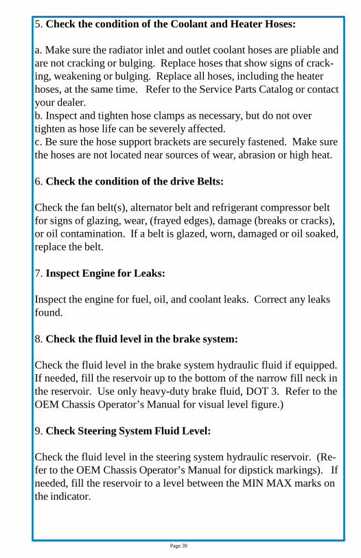
5. Check the condition of the Coolant and Heater Hoses: a. Make sure the radiator inlet and outlet coolant hoses are pliable and are not cracking or bulging. Replace hoses that show signs of crack- ing, weakening or bulging. Replace all hoses, including the heater hoses, at the same time. Refer to the Service Parts Catalog or contact your dealer. b. Inspect and tighten hose clamps as necessary, but do not over tighten as hose life can be severely affected. c. Be sure the hose support brackets are securely fastened. Make sure the hoses are not located near sources of wear, abrasion or high heat.
6. Check the condition of the drive Belts:
Check the fan belt(s), alternator belt and refrigerant compressor belt for signs of glazing, wear, (frayed edges), damage (breaks or cracks), or oil contamination. If a belt is glazed, worn, damaged or oil soaked, replace the belt.
7. Inspect Engine for Leaks:
Inspect the engine for fuel, oil, and coolant leaks. Correct any leaks found.
8. Check the fluid level in the brake system:
Check the fluid level in the brake system hydraulic fluid if equipped. If needed, fill the reservoir up to the bottom of the narrow fill neck in the reservoir. Use only heavy-duty brake fluid, DOT 3. Refer to the OEM Chassis Operator’s Manual for visual level figure.)
9. Check Steering System Fluid Level:
Check the fluid level in the steering system hydraulic reservoir. (Re- fer to the OEM Chassis Operator’s Manual for dipstick markings). If needed, fill the reservoir to a level between the MIN MAX marks on the indicator.
Page 39
10. Check Engine Oil Level: The engine oil level should show between the upper and lower marks on the dipstick. Add enough oil to bring the level up to the operating range. Refer to the Engine Manufacturer’s Operation and Mainte- nance Manual for recommended lubricants and capacities.
MAINTAIN THE CORRECT ENGINE OIL LEVEL. OPERATING THE ENGINE WITH THE OIL LEVEL BELOW THE LOW MARK, OR ABOVE THE HIGH MARK, COULD RESULT IN ENGINE DAMAGE. REFER TO THE OPERATOR’S MANUAL FOR DIPSTICK FLUID LEVEL MARKINGS AND DIPSTICK FLUID LEVEL MARKINGS FIGURE.
Page 40
11. Check Trans Fluid Level: With the vehicle on a level surface, check the fluid level in the trans- mission using one of the following procedures.
THE FLUID MUST BE WARM TO ENSURE AN ACCURATE READING. THE FLUID LEVEL RISES AS TEMPERATURE INCREASES.
a. Hot Check:
1. Operate the transmission in a drive range until normal operating temperature – 160° to 200° F (71° to 93° C) is reached. 2. Put the vehicle into Park. Let the engine run at idle. 3. Pull out the transmission dipstick and wipe it clean, then reinsert it into the filler tube all the way until it stops. Pull out the dipstick and check where the fluid level is on the dipstick. A safe operating level is any level within the “HOT RUN” band (upper) on the dipstick. Refer to the OEM Chassis Operator’s manual for dipstick markings. 4. If the fluid is not within this range, add or drain fluid as needed to bring the level to the top of the “HOT RUN” band. Refer to the OEM Chassis Operator’s Manual for approved transmission lubricants and transmission lubricants and transmission lubricant capacities.
HOT FLUID CAN CAUSE SERIOUS BURNS, AND DAMAGE TO EYES. CARE SHOULD BE TAKEN TO ENSURE ACCIDENTAL CONTACT WITH THE FLUID IS AVOIDED.
b. Cold Check: 1. A cold check may be made when the sump temperature is 60° to 104° F (71° to 93° C), is reached. 2. Run the engine for at least one (1) minute to clear the fluid system of air.
3.With the engine running, pull out the dipstick and wipe it clean, then insert the dipstick back into the filler tube until it bottoms out.
Page 41

12. Check Intake Air Restriction Indicator:
a. Check the Intake Air Restriction Indicator, (if equipped), to determine if the air cleaner filter element needs to be changed. b. Replace the air cleaner element after the first six months and thereafter replace it when the yellow line reaches 25in H2O vacuum or every two years regardless of mileage. After the air cleaner element is replaced, press the rubber button on the bottom of the Air Restriction indicator to reset.
FAILURE TO MAINTAIN A SEALED AIR INTAKE SYSTEM COULD ALLOW ENTRY OF DIRT AND CONTAMINATION INTOTHE ENGINE.THIS COULD ADVERSELY AFFECTTHE ENGINE PERFORMANCE AND COULD RESULT IN ENGINE DAMAGE.
13. Inspect Fuel Tanks and Components:
a. Inspect the fuel tank(s) and fuel line connection. If equipped, be sure the fuel tank shut off valves are open. b. Replace leaking fuel tank(s); repair or replace any lines or connections that are leaking. If equipped with fuel tank shut off valves, be sure the valves are fully open.
NEVER OPERATE THE ENGINE WITH THE FUEL TANK SHUT-OFF VALVES PARTLY CLOSED. THIS COULD DAMAGE THE FUEL PUMP, CAUSING SUDDEN LOSS OF ENGINE POWER, POSSIBLY RESULTING IN SERIOUS PERSONAL INJURY DUE TO REDUCED ENGINE CONTROL.
Page 42
14. For Diesel fuel-powered vehicles, check the fuel level in the tank(s) and be sure the fuel cap vent area is clean. If needed, prime.
Use only ultra or low-sulfur diesel fuels. Low-sulfur diesel fuel has a maximum 0.05% sulfur content compared to .26 to .30 sul- fur. Failure to use low-sulfur diesel fuels may void the warranty on emission components.
DO NOT MIX GASOLINE OR ALCOHOL WITH DIESEL FUEL. THIS MIXTURE COULD CAUSE AN EXPLOSION. WHEN FILLING FUEL TANK(S), DO NOT SMOKE OR USE AN OPEN FLAME NEAR THE FUEL TANKS; COMBUSTION OF DIESEL FUEL OR FUEL VAPORS COULD RESULT. NEVER FILL THE FUEL RANKS TO MORE THAN 95% OF THEIR LIQUID CAPACITY. THIS COULD MAKE THEM MORE LIKELY TO RUPTURE FROM IMPACT, POSSIBLY CAUSING FIRE AND RESULTING IN SERIOUS PERSONAL INJURY OR DEATH BY BURNING.
a. To keep condensation to a minimum, fill the fuel tanks at
the end of each day, but not to more than 95% of liquid capacity. Select the proper grade of fuel as specified by the engine manufacturer. b. Always strain or filter fuel before putting it into the tank(s). This will lengthen the life of the engine fuel filter and reduce the chances of dirt entering the engine. c. Before installing the fuel cap check the vent line for debris. Clean the area around the fuel tank cap with a clean rag, or if necessary, clean with solvent.
Page 43

DO NOT CRANK THE ENGINE FOR MORE THAN 30 SECONDS AT A TIME DURING ANY OF THE FOLLOWING PROCEDURES. WAIT TWO (2) MINUTES AFTER EACH TRY TO ALLOW THE STARTER TO COOL. FAILURE TO DO SO COULD CAUSE STARTER DAMAGE.
Before doing any of the following procedures, make sure there is an adequate amount of fuel in the fuel tank(s). Do not fill the tank(s) to more than 95% of liquid capacity.
d. On vehicles equipped with a single fuel tank, prime the fuel system, if needed. e. Unlock and operate the engine priming pump plunger until resistance is felt. f. Push the plunger in and tighten it by hand. g. Start the engine. If it does not start, more priming is need ed. Once the engine has started, it may run rough. If this occurs, run the engine at low idle until it smoothes out.
On vehicles not equipped with a Priming Pump:
a. Remove the fuel tank cap. b. Loosen the fuel supply line at the fuel transfer pump. c. Partially cover the fuel tank opening with your hand. Using an air hose, apply no more than 5 psi (35 kPs) air pressure to the fuel tank and look for a constant fuel flow at the loosened fuel supply line. d. Remove the air hose and tighten the fuel supply line. e. Start the engine. Once the engine has started it may run rough. If this occurs, run the engine at low idle until it smoothes out.
To prevent fuel loss or entry of air into the fuel line, make sure that all fuel line connections are tight.
f. On vehicles equipped with dual tanks and single suction and return lines (with crossover line), prime the fuel system if needed.
Page 44

Use the same previous steps for vehicles equipped with dual tanks. Perform the procedure on the tank equipped with the supply line.
15. Drain Water from Fuel/Water Separator Daily.
Shut OFF engine. Turn the valve clockwise approximately ½ to 1 turn until draining occurs. Drain the filter sump of water until clear fuel is visible. Turn the valve counterclockwise to close the drain.
DO NOT OVER TIGHTEN VALVE. OVER TIGHTENING CAN DAMAGE THE THREADS AND SEAL.
When draining fluid from a fuel/water separator, drain the fluid into an appropriate container and dispose of it properly. Many states now issue fines for draining fuel/water separators onto the ground. On all types of separators, stop draining fluid when you see fuel come out of the separator drain valve.
Page 45

16. Inspect Front and Rear Suspension:
a. Check for broken spring leaves, loose U-bolts, cracks in the suspension brackets, and loose fasteners in the spring hangers and shackles. Inspect the shock absorbers for loose fasteners and leaks. b. Tighten all loose fasteners. Replace any component that is worn, cracked or otherwise damaged.
DO NOT REPLACE INDIVIDUAL LEAVES OF A DAMAGED FRONT OR REAR SUSPENSION LEAF SPRING ASSEMBLY, REPLACE THE COMPLETE SPRING ASSEMBLY.
VISIBLE DAMAGE (CRACKS OR BREAKS) TO ONE LEAF CAUSES HIDDEN DAMAGE TO OTHER LEAVES. REPLACEMENT OF ONLY THE VISIBLY DAMAGED PART(S) IS NO ASSURANCE THE SPRING IS SAFE. A LOSS OF VEHICLE CONTROL COULD OCCUR. FAILURE TO REPLACE A DAMAGED ASSEMBLY COULD CAUSE AN ACCIDENT RESULTING IN SERIOUS INJURY OR PROPERTY DAMAGE.
17. Check Steering Wheel for Excessive Play:
a. With the front tires straight ahead, turn the steering wheel until motion is observed at the front wheels. b. Align a reference mark on the ruler, and then slowly turn the steering wheel in the opposite direction until motion is again detected at the wheels. c. Measure the lash (free-play) at the rim of the steering wheel. (Refer to the OEM Chassis Operator’s Manual. d. Excessive lash exists if steering wheel movement exceeds 4¾ inch (121mm) with an 18 inch (470 mm) steering wheel. If there is excessive lash, check the steering system for wear or incorrect adjustment of the linkage and steering gear before operating the vehicle.
Page 46

18. Check Engine Oil Pressure Warning System:
a. When the engine is started, the oil pressure warning will come “On” until the oil pressure rises above a preset minimum. b. If the warning system does not come on when the ignition is turned “On”, repair the system.
19. Make sure the electric horn is operating properly:
20. Check windshield Wiper operation, including fluid level:
21. Check the operation of the backup alarm:
Make sure the backup alarm (if equipped) is operating properly.
22. Inspect Exterior Lights:
Turn “On” the headlights; inspect both high and low beams. Inspect turn, stop, backup, and side marker and clearance lights; replace any that are not working.
Page 47

23. Inspect Interior Lighting: If any of the instrument panel gauge bulbs, the dome lights, step well light, reading lights, rear luggage compartment light (if equipped) or the right/left hand turn indicator light bulbs are not working, replace them.
24. Inspect the Tires:
Check tire pressure and inspect each tire for bulges, cracks, cuts & punctures.
The load and cold inflation pressure must not exceed the rim or wheel manufacturer’s recommendations, even though the tire may be approved for a higher load or inflation. Some rims and wheels are stamped with a maximum load and maximum cold inflation rating. If they are not stamped, consult the rim or wheel manufacturer for the correct tire inflation pressure for the vehicle load. If the load exceeds the maximum rim or wheel capacity, the load must be adjusted or reduced.
a. Check the inflation pressure of the tires before each trip, using an accurate tire pressure gauge. Tires should be checked when cool. The correct pressure for each tire is provided on the outer wall of the tire. On standard tires, the pressure should be 120 psi (827 kPa). In- flate the tires to the applicable pressure, if needed. Be sure the valve stem caps are on every tire and that they are screwed on finger tight.
NOTE: Refer to the OEM Chassis Operator’s Manual to check tire infla- tion pressure.
Over-inflation gives the treaded surface of the tire a convex shape (Refer to the OEM Chassis Operator’s Manual for tire figures). This causes extreme tire wear in the middle part of the tire.
Page 48

Refer to the OEM Chassis Operator’s Manual for checking tire inflation pressure, front axle to rear axle rotation, dual assembly rotation and wheel nut tightening sequence drawings.
DO NOT OPERATE THE VEHICLE WITH UNDER-INFLATED OR OVER-INFLATED TIRES. INCORRECT INFLATION CAN STRESS THE TIRES AND MAKE THE TIRE AND RIMS MORE SUSCEPTIBLE TO DAMAGE, POSSIBLE LEADING TO RIM OR TIRE FAILURE AND LOSS OF VEHICLE CONTROL, RESULTING IN SERIOUS PERSONAL INJURY OR DEATH.
If a tire has been run flat or underinflated, check the wheel for proper lockring seating and possible wheel, rim or tire damage before adding air.
b. Moisture inside a tire can result in body ply separation or a sidewall rupture. During tire inflation, compressed air reservoirs and lines must be kept dry. Use well maintained in-line moisture traps and service them regularly. c. Inspect the tires for bulges, cracks, cuts or penetrations. A tire pressure check will assist in uncovering hidden damage. A weekly pressure loss of 4 psi (28 kPa) or more in a tire may indicate damage and the tire should be inspected and repaired or replaced.
Page 49
d. If the tires are wearing irregularly, rotate them. If the front steering axle tires become irregularly worn, move them to the drive axle (Refer to the OEM Chassis Operator’s Manual). Have the front axle alignment checked to determine the cause of irregular tire wear. In a dual assembly, if one tire wears faster than its mate, reverse the position of the two tires (Refer to the OEM Chassis Operator’s Manual). Government regula tions require removal of front axle tires at 4/32-inch (3mm) remaining tread depth and rear axle tires axle tires may be rotated to the drive axle to use the remaining 3/32-inch (1.5mm) tread wear. e. Tires should be inspected for oil contamination. Fuel oil, gasoline, and other petroleum derivatives, if allowed to contact the tires, will soften the rubber and destroy the tire.
Refer to the OEM Chassis Operator’s Manual for checking tire inflation pressure, front axle rota- tion, dual axle rotation and wheel nut tightening sequence drawings.
Page 50

25. Check for Loose Wheel Lug Nuts and Wheel Components:
a. Check the wheel nuts or rim nuts for indications of looseness. Remove all dirt and foreign material from the wheel assembly. b. Dirt or rust streaks from the stud holes, metal buildup around the stud holes or out-of-round or worn stud holes may be caused by loose wheel lug nuts. c. Replace broken, cracked, badly worn, bent, rusty or sprung rings and rims. Be sure that the rim base, lock-ring and side ring are matched according to the size and type.
Note: For removing dual wheel assembly nuts refer to the OEM Chas- sis Operator’s Manual for sequence. For lug tightening sequence refer to the OEM Chassis Operator’s Manual also.
HAVE ANY WORN OR DAMAGED WHEEL COMPONENTS REPLACED BY QUALIFIED PERSONNEL USING THE WHEEL MANUFACTURER’S INSTRUCTIONS AND THE WHEEL INDUSTRY’S STANDARD SAFETY PRECAUTIONS AND EQUIPMENT. OTHERWISE A VEHICLE OR WORKSHOP ACCIDENT COULD OCCUR, POSSIBLY RESULTING IN SERIOUS INJURY OR DEATH.
Note: Refer to the OEM Chassis Operator’s Manual for checking tire pressure, front axle to rear axle rotation, dual assembly rotation and wheel lug tightening sequence drawings.
Page 51

INSUFFICIENT WHEEL NUT (RIM NUT) TORQUE CAN CAUSE WHEEL SHIMMY, RESULTING IN WHEEL DAMAGE, STUD BREAKAGE, AND EXTREME TIRE TREAD WEAR. EXCESSIVE WHEEL NUT TORQUE CAN BREAK STUDS, DAMAGE TREADS AND CRACK DISCS IN THE STUD HOLE AREA. USE THE RECOMMENDED TORQUE VALUES AND FOLLOW THE PROPER TIGHTENING SEQUENCE.
On each wheel stud, the end that faces away from the vehicle may be stamped with an “L” or “R” depend- ing on which side of the vehicle the stud is installed. Studs stamped with a “L” are left-handed threaded and are installed on the “Roadside” of the vehicle. Studs stamped with an “R” are right-hand threads and are installed on the “Curbside” of the vehicle.
26. Test the Service Brakes:
Test the service brakes before leaving the lot. Depress the brake ped- al, release the parking brake, and check that the brake system warning light goes “OUT”. If the warning light remains “ON” after releasing the parking brake, correct the problem before driving off.
27. Test the Parking Brake:
Test the parking brake on a 20% grade. Apply the parking brake with the vehicle on a 20% grade (or as steep of a grade that the vehicle may normally be parked on). The ramp surface should be made of Portland cement or equivalent. If the parking brake does not hold the vehicle, repair the parking brake system.
Page 52

EXTERIOR CHECK LIST To keep the bus in the best condition in terms of safety, convenience, service and operating expense, refer to this checklist daily. Any re- pairs known to be required should be made before the bus is driven. Report any repairs needed to service and maintenance personnel. This check will help to minimize delays due to mechanical and func- tional properties.
EXTERIOR CHECKLIST
1. Make sure that all mirrors, windows and lights are clean and functioning properly. 2. Make sure that the bus exterior is clean and clear of obstructions and debris. 3. Inspect all seams and sealant on the vehicle, including windows, clearance lights, front and rear cap seams, flooring and step tread. The top roof seams, escape hatch, upper clearance lights should be inspected on a six month interval. 4. Check the tire pressures. Inspect tread and sidewalls for damage or unusual wear. 5. Inspect the engine compartment and the ground underneath the bus for fluid leaks.
FINAL WALKAROUND
1. With the parking brake applied, check service and emergency exits. They should all open close, seal and secure properly. 2. Inspect seats and floor for debris or damage. 3. Verify that all interior and exterior lights are functional. 4. Inspect the engine compartment for fluid leaks while the engine is running. 5. Verify that all windows, access panels and emergency equipment are in place and in proper working order. 6. Inspect the underside of the bus and make sure it is clear of obstructions. Always check the rear of the vehicle if backing up is required. 7. Check the wheelchair lift for function. Report any problems to service personnel.
Page 53

DRIVING ON SNOW OR ICE When operating the vehicle on snow or ice, reduce speed gradually. Select a gear range that will not exceed the speed you expect to main- tain. Accelerate or decelerate very gradually to avoid losing traction. It is very important to reach the gear in the lower range selected by letting the transmission shift down automatically while gradually slowing. It is important to slow gradually when a lower range is selected. It is also important that you reach the lower range selected before attempting to accelerate. This avoids unexpected downshifting during acceleration.
DO NOT use the retarder during inclement weather or when the road surfaces are slippery due to ice or rain.
DRIVING THROUGH DEEP WATER, OR SNOW WILL ADVERSELY AFFECT BRAKING PERFORMANCE.
ROCKING THE VEHICLE
This section does not apply to vehicles equipped with ATC (Auto- matic Traction Control).
If the bus is stuck in mud, sand or snow, it may be possible to “rock” out. Shift to “Drive” and apply steady, light throttle – NEVER full throttle. When the bus has rocked forward as far as it will go, apply and hold the service brakes. Allow the engine to return to idle, and then select “Reverse”. Release the brakes and apply a steady, light throttle and allow the bus to rock in “Reverse” as far as it will go. Again, apply and hold the service brakes and allow the engine to idle. Never make Neutral-to Drive or directional shift changes when the engine RPM is above idle.
Page 54

To avoid injury or property damage caused by sudden bus movement, do not shift from “Neutral” to “Drive” or “Reverse” when the throttle is open. Shifting with the throttle above idle causes the transmission to delay engaging unless the throttle is closed within the next three (3) seconds. Leaving the throttle open longer than three seconds causes the transmission to remain in “Neutral”. When the throttle is subsequently closed or brought back down, the transmission can engage without warning, causing sudden movement of the vehicle. Avoid this condition by making shifts from “Neutral” to “Drive” or “Reverse” only at idle.
Do not make “Neutral-to-Drive” or directional shift changes with en- gine RPM above idle. If the wheels are stuck and not turning, do not apply full power for more than 30 seconds. Full power more than 30 seconds under these conditions will cause the transmission to over- heat. If the transmission overheats, shift to “Neutral” and operate the engine at 1200-1500 RPM until it has cooled down (approximately 2-3 minutes). Turn the retarder (if equipped) “OFF” when operating the bus in inclement weather, or when road surfaces are slippery.
JACKING PADS
The following describes the operation using the CBI/GCA supplied jacking pads to jack the BODY ONLY.
Note: The CBI/GCA supplied Jack Pads are to be used to jack ONLY THE BODY enough to reach the OEM jacking points to change a tire. DO NOT USE CBI/GCA supplied jacking pads to lift the tire off of the ground.
Note: Use a 5 ton or 10 ton jack. Block the tires before jacking the unit.
Note: See the OEM Driver’s Manual for specific details.
Page 55

TIRES The tires used on this bus must be of the correct size and must be properly inflated for the load being carried. The Certification Label in the beginning of this manual shows the originally equipped tire size and recommended inflation pressures. To avoid injury, ensure the tires are the proper size, load rating and inflation pressure for the total load carried. Inflation above or below the recommended pressure will restrict the speed at which the vehicle can be safely operated.
Tire Blowout
Stop immediately in a safe place away from traffic flow. Be espe- cially alert for flats of the inside dual tires – these tires can catch fire if driven while flat. Contact service personnel immediately.
Replacement Tires/Pressure Ratings
It is the responsibility of the operating company to make certain that all tire ratings are maintained within allowable limits to prevent the possibility of exceeding the maximum air pressure given on the tire. Since the GVWR and the GAWR’s take into account the load capac- ity of the tires originally installed on the vehicle, any replacement tires must be of the same or greater load rating.
Page 56

Tire Traction Driving, cornering, and braking traction are reduced when water, ice, gravel or snow is on the road surface. When driving on wet or slushy roads, a wedge of water can build up between the tires and the road. This is known as hydroplaning and may cause partial or complete loss of traction, braking ability and steering control. Observe the fol- lowing guidelines when operating in abnormal road conditions:
1. Slow down during rainstorms or if the roads are slushy. 2. Slow down if there is standing water or puddles on the road. 3. Keep tires properly inflated.
Page 57

DAILY CHECKLISTS
ITEM SUGGESTED INSPECTION INITIALS
Fuel
Fill fuel tank with engine "OFF". Fill daily or as needed
Driver's Compartment
Clean & Inspect
Driver's Seat
Check Operation of Ajusting Mechanism
Driver's Cab Window
Check Operation
Windshield
Clean & inspect for Damage
Fire Extinguisher
Check Mounting & Charge Pressure
Firt Aid Kit
Check contents, and replenish as needed
Flare & Reflective Hazard Triangle Kit
Check Contents
Floor Covering
Inspect for damage, wear & tear, and clean
Mirrors (Interior)
Inspect for damage. Adjust for optimal view.
Mirrors (Exterior)
Inspect for loose or damaged support arms & brackets. Adjust for optimal view.
Destination Signs
Inspect for damage & leaks. Check light
Sun Visor
Check to see if visor stays in place. Tighten if necessary
Windshield Wipers & Washer
Check blades for streaking. Fill washer fluid reservoir as needed.
Defroster & Front HVAC Blower
Check operation, by turning "ON" the fan with the motor running.
Dashboard Warning Lights
warm up engine. No red lights should show and no buzzer should sound.
Front Heater
Check for heat with engine running.
Page 58
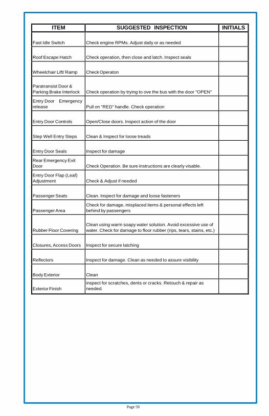
ITEM SUGGESTED INSPECTION INITIALS
Fast Idle Switch
Check engine RPMs. Adjust daily or as needed
Roof Escape Hatch
Check operation, then close and latch. Inspect seals
Wheelchair Lift/ Ramp
Check Operaton
Paratransist Door & Parking Brake Interlock
Check operation by trying to ove the bus with the door "OPEN"
Entry Door Emergency release
Pull on "RED" handle. Check operation
Entry Door Controls
Open/Close doors. Inspect action of the door
Step Well Entry Steps
Clean & Inspect for loose treads
Entry Door Seals
Inspect for damage
Rear Emergency Exit Door
Check Operation. Be sure instructions are clearly visable.
Entry Door Flap (Leaf) Adjustment
Check & Adjust if needed
Passenger Seats
Clean. Inspect for damage and loose fasteners
Passenger Area
Check for damage, misplaced items & personal effects left behind by passengers
Rubber Floor Covering
Clean using warm soapy water solution. Avoid excessive use of water. Check for damage to floor rubber (rips, tears, stains, etc.)
Closures, Access Doors
Inspect for secure latching
Reflectors
Inspect for damage. Clean as needed to assure visibility
Body Exterior
Clean
Exterior Finish
inspect for scratches, dents or cracks. Retouch & repair as needed.
Page 59

ITEM SUGGESTED INSPECTION INITIALS
Rub Rails
Inspect for damage
Skirt Panels
Inspect for damage
Backup Alarm
Inspect for sound when backing up.
Clearance, Sidemarker, & Identification Lights
Check Operation and Clean Lenses if necessary
Curb Lights
Check Operation and Clean Lenses if necessary
Directional Lights
Check Operation and Clean Lenses if necessary
Hazard Warning Lights
Place Hazard Switch to "ON" & Check Operation of front,Side, and Rear Lights
Headlights
Check "HIGH" & "LOW" Beam Operation. Check Headlight Aim & Adjust if necessary.
Horn
Check Operation
Interior Lights
Check Operation
Step Well
Check Operation, Clean lenses
Emergency Exit Lights
Open Emergency Exit Door or Window with Ignition "ON". Warning Light and/ or Buzzer should light up and sound.
Reading Lights
Check Operation and repair as needed.
Exterior Lights
Check Operation. Inspect mounting and clean lenses as needed.
Tires
Check "COLD" for proper air pressure. Look for buldges, knots, cuts, punctures, abrasions, or separations.
Tires
Inspect for damaged valve stems. Replace missing valve stem caps.
Wheels
Inspect Rims & Wheels for damage.
Page 60

NOTES:
Page 61