Embed Size (px)
Citation preview

CIRRUS SR20 AIRCRAFT SYSTEMS
1. GENERAL a. Engines
i. Number of Engines: 1 ii. Number of Cylinders: 6 iii. Engine Manufacturer: Teledyne Continental iv. Engine Model Number: IO-360-ES v. Fuel Metering: Fuel Injected vi. Engine Cooling: Air Cooled vii. Engine Type: Horizontally Opposed, Direct Drive viii. Horsepower Rating: 200 HP @ 2700 RPM
b. Propellers i. Number of Propellers: 1 ii. Propeller Manufacturer: Hartzell iii. Propeller Type: Constant Speed iv. Number of Blades: 2 or 3 v. Propeller Diameter (2 blade): 76.0” (74.5” Minimum) vi. Propeller Diameter (3 blade): 74.0” (72.5” Minimum)
c. Fuel i. Fuel Capacity (U.S. gal.): 58.5 ii. Usable Fuel (U.S. gal.): 56.0 iii. Fuel Grade, Aviation
1. Minimum Octane: 100/130 – Green; 100LL Blue d. Oil
i. Oil Capacity (U.S. qts.) 8 e. Maximum Weights
i. Max. Takeoff Weight (lb.): 3050 ii. Max. Landing Weight (lb.): 3050 iii. Max. Weights in Baggage Compartment: 130 iv. Full Fuel Payload (lb.): 622
f. Standard Airplane Weights i. Standard Empty Weight (lb.): 2050
1. Weight of a standard airplane including unusable fuel, full operating fluids, and full oil
ii. Maximum Useful Load (lb.): 950 1. The difference between the Maximum Takeoff Weight and the Standard Empty
Weight

2. LIMITATIONS a. Airspeed Limitations (KIAS)
i. VR : 66 ii. VAPP : 77 iii. VCLB : 96 iv. V50’ : 77 v. VGLD : 99 vi. VX : 83 vii. VY : 96 viii. VSO : 61 ix. VS1 : 69 x. VFE : 104 (100%), 119 (50%) xi. VNO : 163 xii. VA : 110-130 xiii. VNE : 200
b. Power Plant Limitations i. Engine Manufacturer: Teledyne Continental ii. Engine Model Number: IO-360-ES iii. Power Rating: 200 HP @ 2700 RPM iv. Maximum RPM: 2700 v. Oil Temperature: 240°F (115°C) maximum vi. Oil Pressure:
1. Minimum: 10 PSI 2. Maximum: 100 PSI
c. Flight Load Factor Limits (Max Gross Weight) i. Flaps 0%: +3.8G, -1.9G ii. Flaps 50%: +1.9G, -0G iii. Flaps 100%: +1.9G, -0G
d. Types of Operations i. VFR: Day, Night ii. IFR: Day, Night
e. Fuel Limitations i. Total Capacity: 58.5 U.S. GAL. ii. Total Capacity Each Tank: 29.3 U.S. GAL. iii. Total Usable Fuel: 56.0 U.S. GAL.
1. The usable fuel in this airplane has been determined as 28 gallons in each wing tank
iv. Unusable Fuel 2.5 U.S. GAL. 1. The unusable fuel for this airplane has been determined as 1.25 gallons in each
wing tank in critical flight attitudes 3. AIRFRAME – see Cirrus Manual (7-6)
a. A composite roll cage within the fuselage structure provides roll protection for the cabin occupants
b. The avionics bay is located aft of bulkhead 222 (behind rear baggage compartment) c. Wings each contain a 29.3 gallon fuel tank d. Wings are attached to the fuselage through a spar carry-through located under the two front
seats
4. FLIGHT CONTROLS – see Cirrus Manual (7-8) a. The flight controls use a normal cable, pulley and bell-crank system to connect the control stick to
the elevator and aileron. b. Pitch Trim

i. Pitch Trim system does not move a trim tab. An electric motor moves the flight control to a desired position and keeps it there by changing the tension on a spring cartridge. Simply put, the electric motor adjusts the tension on a spring that holds the flight control in a desired setting (i.e. for takeoff, spring loaded to Takeoff position). The moving of the flight control in turn moves the control stick.
ii. In the event of a elevator control failure, you can use the elevator trim to control the pitch of the aircraft (so long as the elevator is not jammed)
iii. Elevator (pitch) trim is powered by 28 VDC supplied through the 2-amp PITCH TRIM circuit breaker on ESS BUS 2
c. Roll Trim i. Roll Trim operates the same way as the Pitch Trim system ii. Aileron trim is powered by 28 VDC supplied through the 2-amp ROLL TRIM
circuit breaker on ESS BUS 2 d. This aircraft is not equipped with control locks or gust locks, the trim spring cartridges have
sufficient power to overcome any wind gust 5. INSTRUMENT PANEL – see Cirrus Manual (7-14)
a. The left display is called the Primary Flight Display (PFD) and displays the most critical flight data b. The right display is called the Multi Functional Display (MFD) and displays additional engine data,
navigation, checklists, etc. c. Attitude Indicator
i. The Primary Attitude Indicator information is presented on the PFD. Information is provided by the Attitude and Heading Reference System (AHRS)
ii. The Standby Attitude Indicator is electrically powered. A red GYRO flag indicates loss of electrical power
iii. The Standby Attitude Indicator is powered by 28 VDC and is supplied through the 5-amp STDBY ATTD 1 circuit breaker on the ESS BUS 1 and the 5-amp STDBY ATTD 2 circuit breaker on the MAIN BUS 1
d. Airspeed Indicator i. Primary airspeed data is provided by the Air Data Computer and is displayed on the PFD.
Speed starts being displayed at 20 knots e. Altimeter
i. Primary altitude data is provided by the Air Data Computer and is displayed on the PFD. The Altitude Reference Bug can be set using the “ALT SEL” knob on the FMS panel.
f. Horizontal Situation Indicator i. Displayed on PFD; heading data is provided by the Attitude and Heading Reference
System (AHRS) and the onboard magnetometers ii. The HSI heading reference bug is set using the heading selection knob on the FMS
keyboard g. Vertical Speed Indicator
i. Displayed on PFD; data is provided by the Air Data Computer. Rate must exceed 100 feet per minute to be displayed
h. Flight Instruments Review: i. Air Data Computer: Airspeed Indicator, Altimeter, Vertical Speed Indicator ii. Attitude and Heading Reference System (AHRS): Primary Attitude Indicator, Horizontal
Situation Indicator, Turn Coordinator, Slip/Skid indicator iii. ESS BUS 1 – Standby Attitude Indicator iv. MAIN BUS 1 – Standby Attitude Indicator
6. WING FLAPS – see Cirrus Manual (7-22) a. Electrically controlled, single-slotted flaps b. Flap positions:
i. 0% - 0° ii. 50% - 16° iii. 100% - 32°
c. Flaps controlled through a motorized linear actuator mechanically connected to both flaps by a torque tube
d. Flaps are powered by 28 VDC through the 10-amp FLAPS circuit breaker on the NON ESS BUS
e. Flaps up lights are green, Flaps down lights are yellow f. Flap speeds:
i. 50% - 119 knots ii. 100% - 104 knots
7. LANDING GEAR – see Cirrus Manual (7-24) a. Brakes are hydraulically operated, single-disc type brakes b. A temperature sensitive resistor is mounted to each brake assembly which transmit signals via
the Engine Airframe Unit to the Engine Indicating System for brake temperature caution/warning annunciation
8. SEATS – see Cirrus Manual (7-27) a. Do not kneel or stand on the seats. The seat bottoms have an integral aluminum honeycomb core
designed to crush under impact to absorb downward loads (in the event of a crash) b. A crash sensor under the seat contains an accelerometer. This data is linked to the airbags in the
shoulder harness. In the event of rapid deceleration (in the event of a crash) the airbags are deployed
9. ENGINE – see Cirrus Manual (7-30) a. Teledyne Continental IO-360-ES, six cylinder, normally aspirated, fuel-injected engine de-rated at
200 HP at 2,700 RPM b. Power (Throttle) Lever: mechanically linked by cables to the air throttle body/fuel-metering valve
and to the propeller governor i. Moving the throttle adjust the percent power of the engine
c. Mixture Control Lever is mechanically linked to the mixture control valve in the engine-driven fuel pump. The Mixture Control Lever is labeled RICH-MIXTURE-CUTOFF
d. Alternate Air Control is located on the left console near the pilot’s right knee. Pulling the knob opens the alternate air induction door on the engine induction air manifold, bypassing the air filter and allows warm unfiltered air to enter the engine
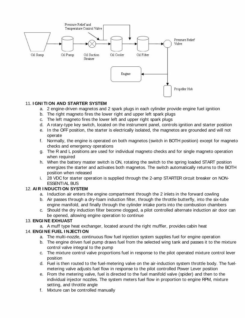
10. ENGINE LUBRICATION SYSTEM a. Wet-sump, high-pressure oil system for engine lubrication and cooling b. Oil is drawn from an 8 quart capacity sump through an oil suction strainer screen and directed to
the engine-mounted oil cooler c. Oil cooler is equipped with a pressure relief and temperature control valve set to bypass oil if the
temperature is below 170ºF or the pressure drop is greater than 18 PSI d. Bypass or cooled oil is then directed through the 1 quart, full-flow oil filter, a pressure relief valve,
and then through oil galleries to the engine rotating parts and piston inner domes e. Complete oil system is located in the engine, the oil filler cap can be accessed through a door on
the top left side of the engine cowling
11. IGNITION AND STARTER SYSTEM
a. 2 engine-driven magnetos and 2 spark plugs in each cylinder provide engine fuel ignition b. The right magneto fires the lower right and upper left spark plugs c. The left magneto fires the lower left and upper right spark plugs d. A rotary-type key switch, located on the instrument panel, controls ignition and starter position e. In the OFF position, the starter is electrically isolated, the magnetos are grounded and will not
operate f. Normally, the engine is operated on both magnetos (switch in BOTH position) except for magneto
checks and emergency operations g. The R and L positions are used for individual magneto checks and for single magneto operation
when required h. When the battery master switch is ON, rotating the switch to the spring loaded START position
energizes the starter and activates both magnetos. The switch automatically returns to the BOTH position when released
i. 28 VDC for starter operation is supplied through the 2-amp STARTER circuit breaker on NON-ESSENTIAL BUS
12. AIR INDUCTION SYSTEM a. Induction air enters the engine compartment through the 2 inlets in the forward cowling b. Air passes through a dry-foam induction filter, through the throttle butterfly, into the six-tube
engine manifold, and finally through the cylinder intake ports into the combustion chambers c. Should the dry induction filter become clogged, a pilot controlled alternate induction air door can
be opened, allowing engine operation to continue 13. ENGINE EXHUAST
a. A muff type heat exchanger, located around the right muffler, provides cabin heat 14. ENGINE FUEL INJECTION
a. The multi-nozzle, continuous flow fuel injection system supplies fuel for engine operation b. The engine driven fuel pump draws fuel from the selected wing tank and passes it to the mixture
control valve integral to the pump c. The mixture control valve proportions fuel in response to the pilot operated mixture control lever
position d. Fuel is then routed to the fuel-metering valve on the air-induction system throttle body. The fuel-
metering valve adjusts fuel flow in response to the pilot controlled Power Lever position e. From the metering valve, fuel is directed to the fuel manifold valve (spider) and then to the
individual injector nozzles. The system meters fuel flow in proportion to engine RPM, mixture setting, and throttle angle
f. Mixture can be controlled manually

g. An electric fuel pump provides fuel boost for vapor suppression and for priming 15. ENGINE COOLING
a. Engine components discharge heat to the oil and then to the air passing through the oil cooler, and by discharging heat to air flowing past the engine
b. Cooling air enters the engine through 2 inlets in the cowling and aluminum baffles direct the air over the engine cylinders and cooling fins where the heat transfer takes place
c. Air exits the cowling through 2 vents in the aft portion of the cowling. No cowl flaps are used 16. PROPELLER
a. Aircraft is equipped with a constant speed propeller with governor and can be configured with either a 2 blade propeller (76”) or a 3 blade propeller (74”)
b. The propeller governor changes propeller pitch to regulate engine and propeller RPM. The governor sense engine speed by means of flyweights and sense throttle setting by a cable connected to the power control lever (PCL)
c. The PCL position sets an engine percent power. Percent power is a function of engine manifold absolute pressure and propeller RPM
i. % Power = MAP + RPM d. When the PCL is set it moves a throttle control cable and a governor control cable. The governor
control cable moves a screw (up/down) in the propeller governor that moves a set of flyweights inside the governor.
e. The flyweights move in when the engine is set to a higher RPM and out when the engine is set to a lower RPM. The flyweight position (in/out) moves a valve that controls oil flow to the propeller hub piston. The only way to close the valve is when the flyweights return to the neutral position. This “neutral position” is set at 2500 RPM during normal cruise flight and 2700 RPM at max power.
f. When the aircraft is flying, the position of the flyweights ensures constant RPM. For example, if the propeller starts moving faster (i.e. in a descent) than the set RPM level (2500, 2700, etc.) the fly weights will move out, therefore bringing oil into the propeller hub and allowing the pitch of the blades to increase (which slows the propeller back down to the desired RPM). The position of the flyweights ensures that oil is constantly being taken in/out of the propeller hub piston therefore allowing a constant RPM is held.
g. Manifold Absolute Pressure is the air pressure going into the intake of the engine. The PCL directly controls the MAP through a throttle cable
h. According to the percent power equation: % Power = MAP + RPM, once a given RPM is set the only variable that needs to be set is MAP in order to give a % Power. When the PCL is set, the physical position of the throttle sets percent power and the throttle control cable automatically determines MAP in order to produce a constant % Power.
17. FUEL SYSTEM a. 56 gallon usable wet-wing fuel storage system b. System:
i. 29.3 gallon capacity (28 gallon usable) vented integral fuel tank ii. Fuel collector sump in each wing iii. 3 position selector valve (LEFT, RIGHT, OFF) iv. Electric fuel pump v. Engine driven fuel pump
c. Fuel is gravity fed to the associated collector sumps where the engine driven fuel pump draws fuel through a filter and selector valve to pressure feed the engine fuel injection system. The electric fuel pump is provided for priming and vapor suppression
d. The Electric fuel pump is controlled by the fuel pump switch in the cockpit. It is linked with the oil system and allows HIGH BOOST PRIME when oil pressure is less than 10 PSI. The LOW BOOST works regardless of oil pressure and sends a consistent 4-6 PSI boost to the fuel flow for vapor suppression in a hot fuel condition.
e. The fuel pump operates on 28 VDC through the 5-amp FUEL PUMP circuit breaker on MAIN BUS 2

ELECTRICAL SYSTEM
f. Aircraft is equipped with a 2 alternator, 2 battery 28 volt direct current (VDC) electrical system designed to reduce the risk of electrical system faults

g. Primary power is supplied through a 28 VDC negative ground electrical system. Electrical power consists of 2 alternators controlled by a Master Control Unit (MCU) mounted on the left firewall and 2 batteries for starting and electrical power storage
h. Alternator 1 (ALT 1) is a belt driven, 85 amp alternator mounted on the right front of the engine i. Alternator 2 (ALT 2) is a gear driven, 75 amp alternator mounted on the accessory drive at the
rear of the engine j. ALT 1 is regulated to 28 V and ALT 2 is regulated to 28.75 V k. Battery 1 (BAT 1) is a 24 volt, 11-amp hour battery mounted on the right firewall. BAT 1 is
charged from the Main Distribution Bus 1 in the MCU. l. Battery 2 (BAT 2) is composed of two 12 volt, 7-amp hour batteries connected in series to
provide 24 volts and 7-amp hours. BAT 2 is located behind the aft cabin bulkhead below the parachute canister. BAT 2 is charged from the circuit breaker panel ESS BUS 1.
See Cirrus POH page 7-47 for complete electrical diagram.

CIRRUS SR20 SIMPLIFIED ELECTRICAL DIAGRAM

18. STALL WARNING a. As the airplane approaches a stall, the low pressure on the upper surface of the wings moves
forward around the leading edge of the wings. As the low pressure area passes over the stall warning inlet, a slight negative pressure is sensed by the pressure switch. The pressure switch then provides a signal to cause the warning horn to sound, the red STALL warning CAS annunciation to illuminate
b. The system operates through 28 VDC supplied through the 2-amp STALL WARNING circuit breaker on the ESS BUS 2
19. PITOT STATIC SYSTEM a. The Pitot-Static system provides ram air and static air pressure to operate the:
i. Airspeed Indicator (ASI) ii. Altimeter (ALT) iii. Vertical Speed Indicator (VSI) iv. Air Data Computer (ADC)
b. The only “true” Pitot/Static instrument is the Airspeed Indicator. It requires both ram air from the pitot tube and static air from the 2 static ports on the fuselage
c. The pitot tube and static ports send direct pressure to the Standby Instruments and are displayed directly on the gauges
d. The pitot tube and static ports send direct pressure to an Air Data Computer that precisely interprets the data and displays it on the PFD
e. In the case of static port blockage, an internal Alternate Static source is located to provide static pressure from inside the cockpit. The Alternate Static switch is located to the right of the pilot’s leg
f. In case of pitot tube blockage (e.g. from ice), pitot heat is electrically supplied by 28 VDC from the NON ESS BUS.

20. AVIONICS
a. Integrated Avionics Unit – The MFD and PFD receive information from 2 IAUs. They function
as main communication hubs linking all other instruments with the PFD and MFD. Each contains a GPS/WAAS receiver, VHF communication, Navigation/Glideslope receivers, and a flight director

b. Air Data Computer – processes data from the pitot static system and outside air temperature sensors. These units provide pressure altitude, airspeed, vertical speed and OAT information to the system
c. Engine and Airframe Sensors – receives and processes signals from engine and airframe sensors and communicates that information to the IAU
d. AHRS – provides aircraft attitude and heading information to both the PFD and the primary IAU. The AHRS contains advanced sensors including accelerometers and rate sensors and interfaces the magnetometer to obtain magnetic field information. It also communicates with the Air Data Computer to obtain air data and with both IAUs to obtain GPS information
e. Magnetometer – measures local magnetic field and sends the data to the AHRS system for processing to determine aircraft magnetic heading
f. Transponder – communicates with the IAU and is controlled via the PFD soft-keys or the GCU controller keypad
21. EMERGENCY LOCATOR TRANSMITTER a. Located behind the aft cabin bulkhead to the right of aircraft centerline b. ELT remote switch is labeled ON-OFF-ARMED, it is selected at ARMED for normal operation c. ELT transmits VHF band audio sweeps on 121.5 Mhz and 243.0 Mhz approximately 0.5 seconds
apart 22. FIRE EXTINGUISHER
a. Halon 1211/1301