Embed Size (px)
Citation preview

Building a 30” Turntable
Introduction
I wanted a turntable at the North end of my Mystic Mountain railroad to turn trains for point-to-
point running – and for visual interest. After measuring all my engines I decided I needed a 30”
turntable. This is (just) sufficient for a Bachmann Ten-Wheeler and a Porter 0-4-0 with its
battery car. My requirements were: inexpensive and low maintenance. The second meant not
using wood or steel. I could use acrylic, but resin casting is our business so I have equipment for
making molds and casting parts and decided to go this route for the turntable bridge. I also have
experience casting in white concrete which would be useful to make the pit walls.
The design
The bridge would be made with two (identical) side panels joined with spacers. The pit walls
would be cast on a circle of wood and then slid into place on a concrete base. The center pivot
locates the bridge in the pit but supports no weight. The weight is supported by the two wheels at
the ends of the bridge which ride on the rail in the bottom of the pit. With this in mind perhaps
you can see that the pivot must be in the exact center of the pit and bridge so that the bridge ends
do not contact the pit side at any point. And the height of the pit side above the pit rail must be
consistent around the pit so that the vertical alignment of the bridge track with the other turntable
tracks will be correct all around the circle.
The bridge is formed from two detailed sides glued together with spacers. You can choose the
width you want easily this way. The center spacers include the center hole for the pivot point.
The end spacers also mount the support wheels that ride on the pit rail.
Building the bridge
The basic steps to build the bridge are:
1) Create a single detailed side panel,
2) Create spacers for a single side of the bridge,
3) Make silicone molds for above,
4) Cast two bridge sides and two sets of spacers from resin,
5) Glue bridge sides with spacers and paint,
6) Glue bearing into center holes in spacers,
Make a bridge side out of acrylic or wood, whatever you’re most comfortable working with.
Make the length 1/2” shorter than the final length to allow 1/4” clearance at each end between
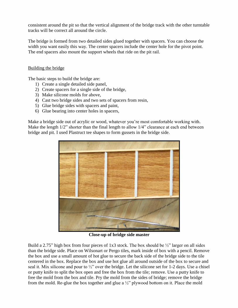
bridge and pit. I used Plastruct tee shapes to form gussets in the bridge side.
Close-up of bridge side master
Build a 2.75” high box from four pieces of 1x3 stock. The box should be ½” larger on all sides
than the bridge side. Place on Wilsonart or Pergo tiles, mark inside of box with a pencil. Remove
the box and use a small amount of hot glue to secure the back side of the bridge side to the tile
centered in the box. Replace the box and use hot glue all around outside of the box to secure and
seal it. Mix silicone and pour to ½” over the bridge. Let the silicone set for 1-2 days. Use a chisel
or putty knife to split the box open and free the box from the tile; remove. Use a putty knife to
free the mold from the box and tile. Pry the mold from the sides of bridge; remove the bridge
from the mold. Re-glue the box together and glue a ½” plywood bottom on it. Place the mold

inside the box. You now have a secure way to move the mold which also constrains the mold to
retain its correct shape. You will pour two resin bridge sides in this mold. When you pour them,
use a vibrating sander against the box to reduce air bubbles in the cast part. After removing the
castings, you’ll probably still find some air bubbles in the part. You can fill these if you wish
using putty.
Mold of bridge side
Cutting excess mold material away
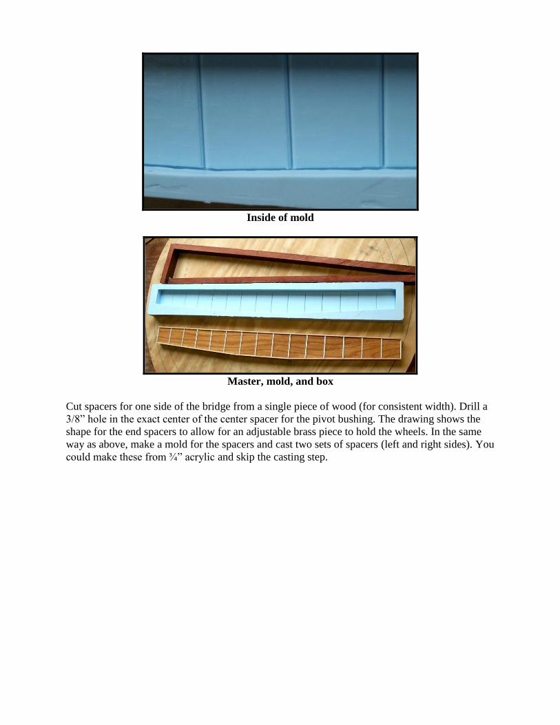
Inside of mold
Master, mold, and box
Cut spacers for one side of the bridge from a single piece of wood (for consistent width). Drill a
3/8” hole in the exact center of the center spacer for the pivot bushing. The drawing shows the
shape for the end spacers to allow for an adjustable brass piece to hold the wheels. In the same
way as above, make a mold for the spacers and cast two sets of spacers (left and right sides). You
could make these from ¾” acrylic and skip the casting step.
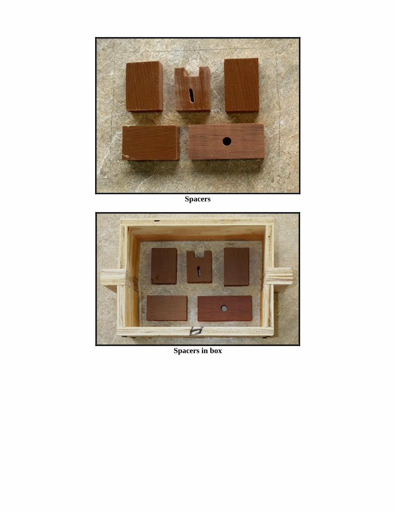
Spacers
Spacers in box

Silicone poured over spacers
I used Urethane glue (e.g. Gorilla glue) to assemble the sides and spacers. Start by carefully
marking the exact center of the bridge sides. Assemble the bridge upside down on a FLAT
surface. Use a square to align the two sides.
Use a ¼”-1/2” scrap to space one center spacer from the top of the bridge (now on the bottom).
Align the other center spacer with the bottom of the bridge (now on the top). Use a 3/8” drill bit
to ensure the holes are aligned. Glue and clamp.
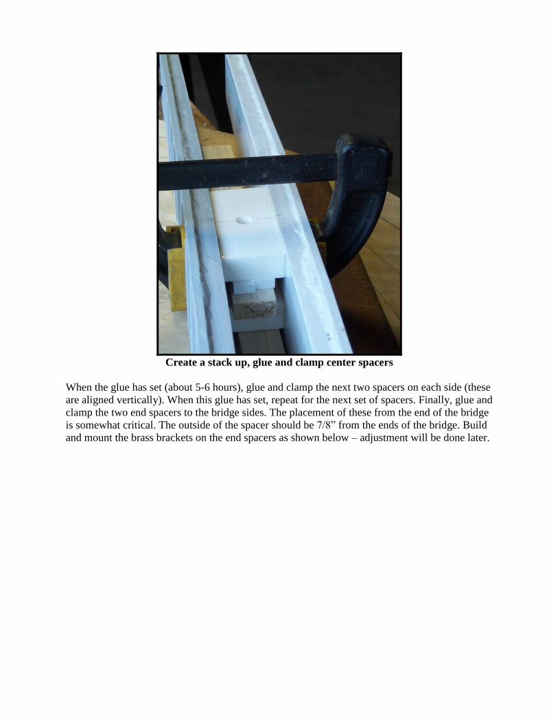
Create a stack up, glue and clamp center spacers
When the glue has set (about 5-6 hours), glue and clamp the next two spacers on each side (these
are aligned vertically). When this glue has set, repeat for the next set of spacers. Finally, glue and
clamp the two end spacers to the bridge sides. The placement of these from the end of the bridge
is somewhat critical. The outside of the spacer should be 7/8” from the ends of the bridge. Build
and mount the brass brackets on the end spacers as shown below – adjustment will be done later.

If you want a walkway on the bridge, construct it from plastic and brass but don’t mount it yet.
Prime and then spray the bridge flat black with exterior paint. Wait to cut and mount the track
until the pit is constructed and the bridge mounted and you can see how close you came to
centering everything.
Building the pit wall
The pit wall is cast in white concrete on a 36” circular piece of ¾” plywood. Mark a centerpoint
on the plywood. Use a trammel to draw circles of 15” and 16.5” radii. Cut about 60 pieces of 1x2
lumber 3” long. About every 3” around these two drawn circles, glue with white wood glue one
of these pieces standing upright – on the inside of the inner circle and on the outside of the outer
circle. Cut a piece of 4” wide Aluminum flashing 8.5 ft. long. This will form the inner side of the
pit wall. Place an end about 3” from an upright and hot glue the flashing to the upright. Proceed
around the circle gluing the flashing to all the uprights. This will give you a smooth, consistent
wall. Do likewise with a 9.5 ft. long piece of flashing to make the outer wall of the pit. Use
caulking to seal the bottom and ends of the flashing. Now coat the plywood on the bottom of the
mold with Vaseline being sure to work it into the joint between the flashing and the plywood to
seal it. At several places around the inside of the mold, mark the point 3 1/8” above the plywood
base. You will fill to this point.
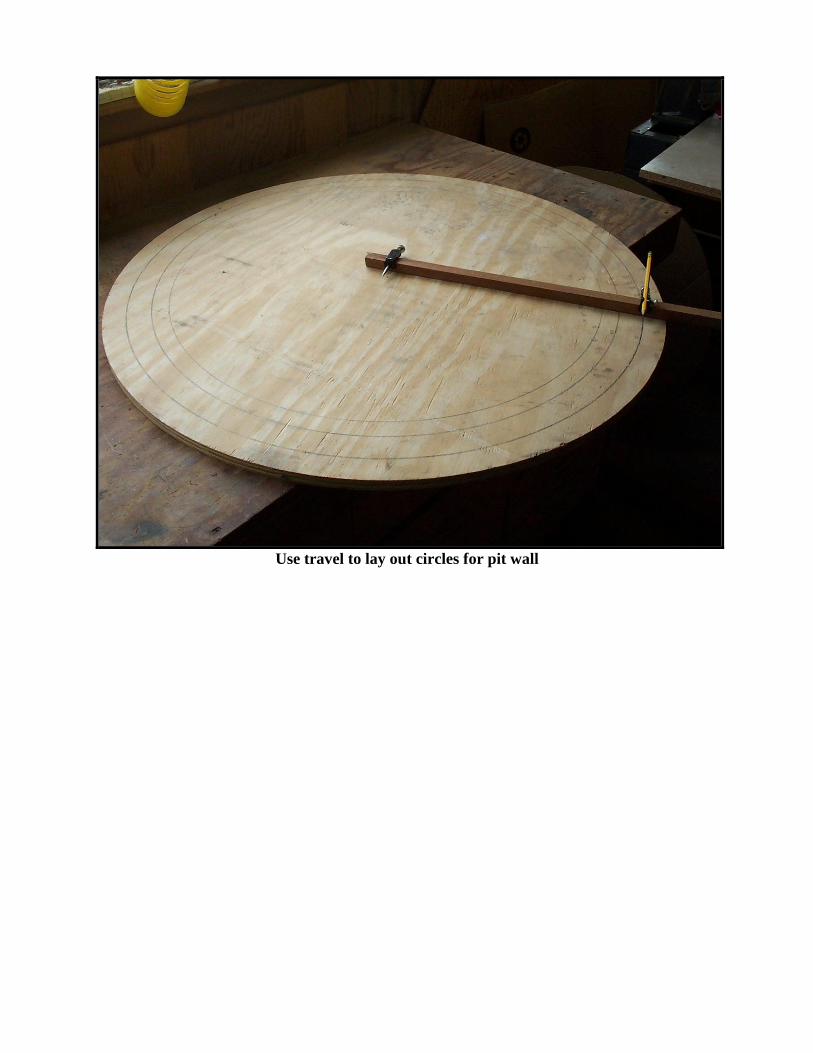
Use travel to lay out circles for pit wall
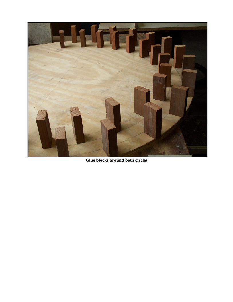
Glue blocks around both circles

Outside wall in place – sealed with caulking
Mold ready for pouring
Place the mold on a LEVEL surface – shim as needed to achieve this. Dry mix 2 parts sand with
one part white or gray Portland cement (depending on the color pit walls you want). Add water

to create a slightly soupy mix. Pour into the mold. Use a vibrating sander against the edge of the
plywood or in the middle of the circle to get the mix to flow around the circle and remove air
bubbles. Keep adding mix and vibrating until you reach the 3 1/8” point all around. It’s
important that the wall height be uniform all around. Allow this to set for 3-7 days depending on
temperature.
Use a hammer to break the uprights off and pull off the flashing. If you’re ambitious, you can use
a hobby grinder to carve the inside of the wall to look like blocks or stones.
Building the pit
The pit is built on top of a FLAT, LEVEL concrete pad. Excavate a 42” square for the turntable
8-9” deep below track level. The dirt underneath should be packed solid – you don’t want it
settling later. Construct a 3’ square (inside) box from lumber with flat, true sides – plane the
lumber, if necessary (it doesn’t have to be square – built a round box if you like). Stake this
securely so that the top of the box is level and 3 1/8” below track level (the BOTTOM of the ties
-- the height of the pit wall). Put about 2” of sand in the bottom for drainage. Cut a piece of ½”
hardware cloth about 33” square. Put a 1” layer of concrete over the sand. Put in the hardware
cloth and fill the box with concrete. Work it good around the sides to get rid of air pockets.
Screed it and work the surface to smooth it. For drainage you want 4-6 holes around the pit. You
can use ¼” dia. nails or wood dowels and drill these larger later. You can also use ¾” PVC –
these won’t go through the screening but you can drill through later. Let the concrete cure for 2-5
days depending on the temperature. Remove the form and drill out the holes all the way through
the concrete into the sand. Fill the holes with ¼” granite or something similar to allow drainage –
fines or sand is too small and will plug up. This will give you a flat, level 3+” slab of concrete to
build on.

Pouring the turntable pad
Locate the center of the slab (or where you want the center of the turntable to be as long as it’s
not too far from the center of the slab). Drill a 3/8” hole in the center for the pivot bushing. Drill
this as close to vertical as you can about 2” deep; you don’t want to go all the way through.
Again with a trammel, draw circles of radii 14 7/8” and 13 ½”. The first will be used to align the
pit wall and the second to align the ties for the pit rail.
Mounting the bridge
The purpose of the center shaft and bearing is to locate the turntable, not support any weight. The
critical thing here is to make the bearings in the concrete platform and in the bridge as close to
vertical as possible. For bearings I found both bronze bearings (expensive) and thick walled
brass tubing. A ¼” brass rod will serve as center post. Press a bearing into the top and bottom
center spacers in the bridge. If the holes were well aligned when the spacers were glued, you
should be able to pass a ¼” rod through both easily.
Seal one end of a 1-2” long bearing with a small piece of brass strip. Solder a wire or piece of
brass on the other end – to be used to pull it back out of the hole.
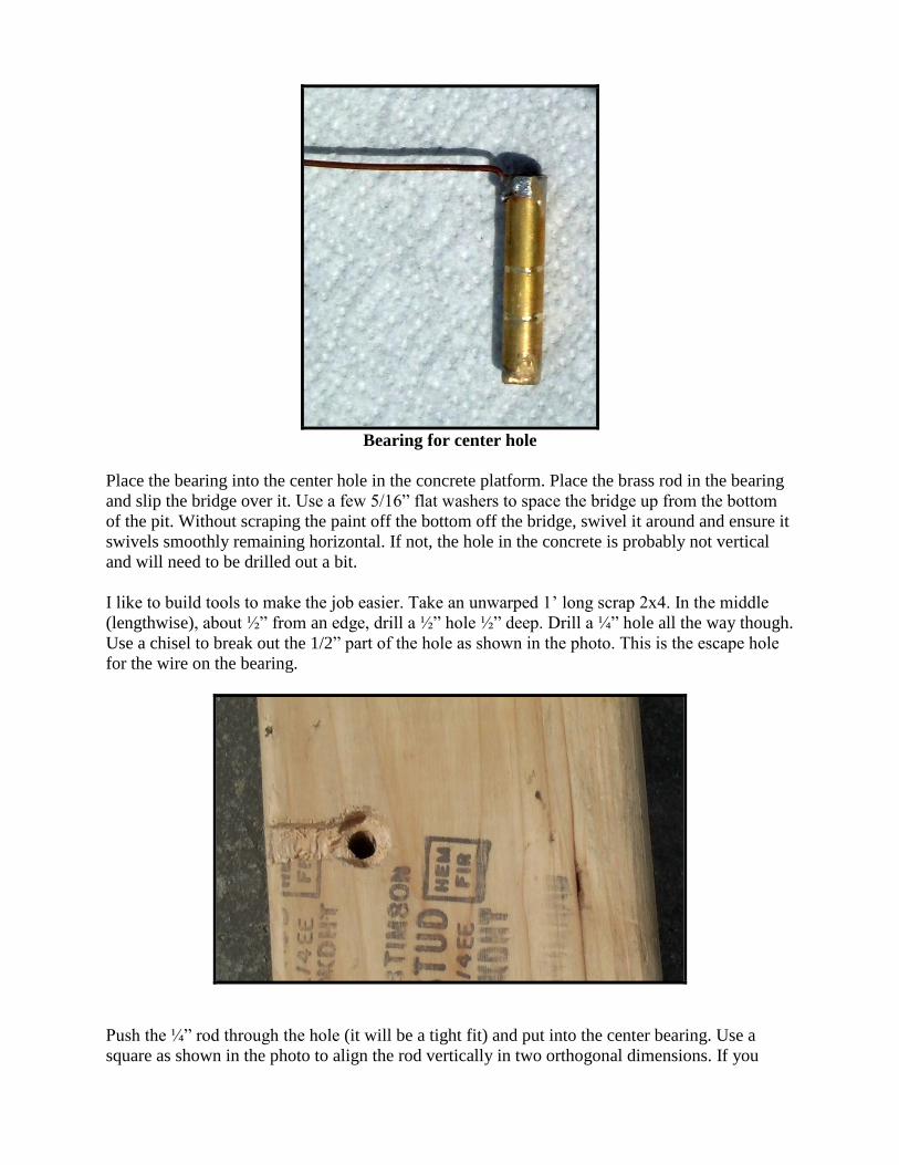
Bearing for center hole
Place the bearing into the center hole in the concrete platform. Place the brass rod in the bearing
and slip the bridge over it. Use a few 5/16” flat washers to space the bridge up from the bottom
of the pit. Without scraping the paint off the bottom off the bridge, swivel it around and ensure it
swivels smoothly remaining horizontal. If not, the hole in the concrete is probably not vertical
and will need to be drilled out a bit.
I like to build tools to make the job easier. Take an unwarped 1’ long scrap 2x4. In the middle
(lengthwise), about ½” from an edge, drill a ½” hole ½” deep. Drill a ¼” hole all the way though.
Use a chisel to break out the 1/2” part of the hole as shown in the photo. This is the escape hole
for the wire on the bearing.
Push the ¼” rod through the hole (it will be a tight fit) and put into the center bearing. Use a
square as shown in the photo to align the rod vertically in two orthogonal dimensions. If you

can’t get it vertical, you may have to drill out the hole in the concrete a bit. Slowly add sand to
the center hole so that the bearing extends from the top of the hole about 1/16”.
Bearing protrudes 1/16” from concrete
Use epoxy to glue the bearing into the hole using the tool to hold it in vertical alignment while
the glue sets. When set, add epoxy around the top of the bearing to seal (waterproof) the outside
of the bearing in the hole.
Vertical alignment of bearing is critical
Once the glue sets, slip the rod into the bearing. Put a few 5/16” washers between the bearing
and the bridge to keep the bridge from scraping on the concrete. Recheck for smooth rotation.
Remove the bridge.
Mounting the pit walls and pit rail
Measure the diameter of the pit walls at several points. It should be ½” larger than the bridge
length. If it’s less than ¼” at any point, you’ll need to trim the bridge length to get the required
clearance. If necessary, trim the same amount from both ends to keep the center in the center.

Carefully slide the pit wall off the plywood into position and use the 14 7/8” circle to align it.
Double check by measuring the radius to many points on the pit wall. With epoxy glue four of
those 1x2 uprights used to cast the wall to the concrete platform to hold the pit wall in place.
You may wish to build a box larger than the pit wall and pour concrete around the pit to the level
of the top of the pit. Or perhaps just fill the area with ballast.
Saw four feet of tie strips to leave about ¼” of tie on the inside of the tie plates. Bend a total of
88” of code 250 rail to 27 1/2” dia. and insert into tie strips with the finished tie end towards the
inside (trim the length as it’s installed). Place the pit rail around the edge of the pit wall. It’s
critical that the rail be circular so align the tie ends to the 13 ½” radius circle you drew. Anchor
the tie strip with urethane glue. You may need to use screws in a few places or put a shim
between a tie end and the pit wall. Try to get it as true to circular as you can. I found it easier to
start gluing on the side away from the joints in the rail and work towards the joints. The joint
areas needed the screws and shims to force them into position.
Slip the bridge over the center post and adjust the wheels on the end of the bridge to ride on the
pit rail and give the bridge the same height as the pit wall. First, the pulleys must be mounted to
have sufficient play on the #10 bolt to accommodate any out-of-roundness of the pit rail. Slowly
rotate the bridge through 360 degrees looking at the pulleys at each end to see if any run out of
play at any point. Adjust the bolt out to increase outward play. Add/subtract inside washers to
adjust inward play. Too much play will allow the pulleys to ride up and off the rail.

Bracket and wheels to ride on the pit rail
If necessary, shorten the ¼” vertical shaft so it doesn’t protrude above the bushing in the bridge.
Glue a scrap of brass to cover the center hole (don’t get glue in the hole) and paint it black. Then
cut a piece of track equal to the pit diameter plus ½” and anchor it to the top of the bridge using
#4 stainless self-tapping screws; this must centered both along length and width. Now you can
run your access tracks to your new turntable. I anchored each access track with a screw through
the end tie into the pit wall.

Electrical connections
If you need to power the track on the bridge, I suggest wiring it to the center post bearing and the
wheels on the ends.
Finishing touches
Mount the walkway on the bridge if you built one.
Carve and/or paint the pit walls.
Glue gravel (fines) on the pit floor.
Paint any visible screw heads black.
Grease the center pivot rod. Note that every time you replace the bridge you need to
check that the pulley wheels are seated on the pit rail properly.
If you have tracks to the turntable exactly 180 apart, small errors in construction may
cause the tracks at both ends to not be aligned exactly at both rotations of the turntable.
You can chamfer the rails (increase gauge slightly at the ends) on the bridge and the entry
tracks to help avoid derailments.
Build a roundhouse – that’s a project for another day.
Parts list
4x ¼” radius x ¼” wide pulley wheel
4x 10-32 brass screws 1.25” long
8x 10-32 brass nuts
8-12x #10 brass flat washers
2x 6-32 brass screws 1.25” long
2x 6-32 brass nuts
2x #6 shake washers
2x #6 lock washers
4x #6 brass flat washers
2x fabricated brass brackets 2”l x 1.375”w x .060” t
2x brass bushings 3/8” OD x .25” ID x .75” long
1x brass bushing 3/8” OD x .25” ID x 1.5-2” long
1x ¼” x 6” long brass rod
8’ code 250 rail (Al or NS recommended)
4’ code 250 tie strips
2x code 250 rail clamps
4-6x #4 stainless self-tapping screws ½” – ¾” long
Misc. stainless or brass screws to anchor pit rail and access tracks
36” dia. ¾” plywood round
17’ 4” aluminum flashing
Misc. 1x2 lumber
Urethane and epoxy glues
If you’re going to make your own molds for the bridge, you’ll also need:

~6’ 1x3 lumber
½” plywood 3’ x 10”
Material to make bridge side master and spacer master
Silicone mix
Resin mix
3x Wilsonart or Pergo tiles
Tools needed
Table or radial arm saw
Drill press
Drill bits – 5/32”, 13/64”
Drill bits – wood: ¼”, 1/2”
Drill bits - masonry: 3/8”, ½”
Hot glue gun
Finish and belt sander
Screw drivers, pliers, and wrenches
Clamps