Embed Size (px)
Citation preview

Bolt Preload Theory and ApplicationBolt Preload Theory and Application
with Femap and NX Nastran
1 / 15©2011 – All Rights Reserved
Bolt Preload Theory and Application
Table of Contents
1. Introduction …………………………………………………………………………………………………… 3
2. Setting up the Model ……………………………………………………………………………………… 4
3. Bolt Regions …………………………………………………………………………………………………… 5
4. Defining a Bolt Preload …………………………………………………………………………………… 6
5. Contact Regions ……………………………………………………………………………………………… 7
6 Classic Example of Bolt Preload 86. Classic Example of Bolt Preload ………………………………………………….…………………… 8
7. Idealization of Bolt Preloads ………………………………………………………………….……….. 10
8. Bolt Preloads with Plate Models ………………………………………………………………….…. 12
9. Bolt Preloads in Solid Models ………………………………………………………………….……… 13
10. Summary ………………………………………………………………….……………………………………. 14
©2011 – All Rights Reserved 2©2011 – All Rights Reserved
Bolt Preload Theory and Application
Introduction
What is bolt preload?Bolt preload is used to clamp together two plates or two structures and create a frictional lock between the members and reduce p p g pthe effects of cycling loading on the bolt. With respect to the latter (i.e., bolt fatigue), bolt preload can make all the difference between a safe, long‐lasting structure or catastrophic failure.
Where to use bolt preload?Bolt preload is not a free lunch. To effectively use bolt preload on FEA connections requires many additional steps and it converts l l h l l l h ( ) h b l l d l d d h ( )a linear run into a nonlinear run that requires two sequential nonlinear analysis where (i) the bolt preload is applied and then (ii)
the external structure load is applied.
What is covered in this white paper?This white paper will cover a the basics of setting up you model for bolt preload, theoretical foundation, examples of its use and a bolt fatigue primerbolt fatigue primer.
Engineering Comment:Bolt preload adds quite a bit of complexity to any model since the analysis procedure is nonlinear (geometrically nonlinear) andthat two sequential nonlinear runs are required to arrive at the final “bolt preload solution”. The utility of this approach lies in its ability to quantitatively calculate the bolt axial and shear forces for any type of bolted connection. Additionally, if bolt fatigue is important, then a bolt preload approach is invaluable.
©2011 – All Rights Reserved 3©2011 – All Rights Reserved
Bolt Preload Theory and Application
Setting up the Model for Bolt Preloading
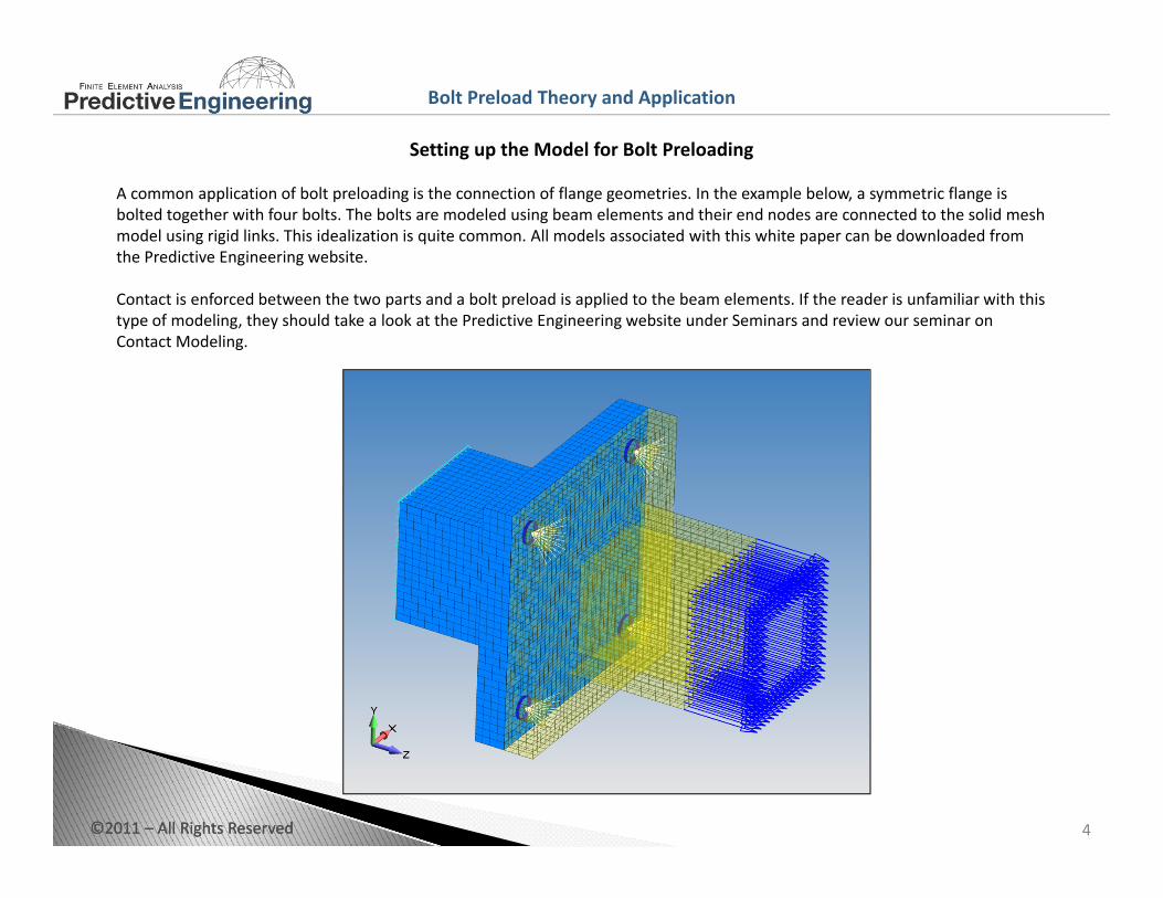
A common application of bolt preloading is the connection of flange geometries. In the example below, a symmetric flange is bolted together with four bolts. The bolts are modeled using beam elements and their end nodes are connected to the solid mesh model using rigid links. This idealization is quite common. All models associated with this white paper can be downloaded from the Predictive Engineering website.
Contact is enforced between the two parts and a bolt preload is applied to the beam elements. If the reader is unfamiliar with this type of modeling, they should take a look at the Predictive Engineering website under Seminars and review our seminar on Contact Modeling.
©2011 – All Rights Reserved 4©2011 – All Rights Reserved
Bolt Preload Theory and Application
Bolt Regions
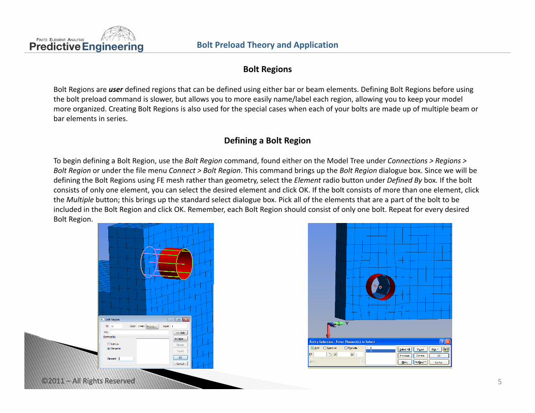
Bolt Regions are user defined regions that can be defined using either bar or beam elements. Defining Bolt Regions before using the bolt preload command is slower, but allows you to more easily name/label each region, allowing you to keep your model more organized. Creating Bolt Regions is also used for the special cases when each of your bolts are made up of multiple beam orbar elements in series.
Defining a Bolt Region
To begin defining a Bolt Region, use the Bolt Region command, found either on the Model Tree under Connections > Regions > Bolt Region or under the file menu Connect > Bolt Region. This command brings up the Bolt Region dialogue box. Since we will be defining the Bolt Regions using FE mesh rather than geometry select the Element radio button under Defined By box If the boltdefining the Bolt Regions using FE mesh rather than geometry, select the Element radio button under Defined By box. If the bolt consists of only one element, you can select the desired element and click OK. If the bolt consists of more than one element, click the Multiple button; this brings up the standard select dialogue box. Pick all of the elements that are a part of the bolt to be included in the Bolt Region and click OK. Remember, each Bolt Region should consist of only one bolt. Repeat for every desired Bolt Region.
©2011 – All Rights Reserved 5©2011 – All Rights Reserved
Bolt Preload Theory and Application
Defining a Bolt Preload
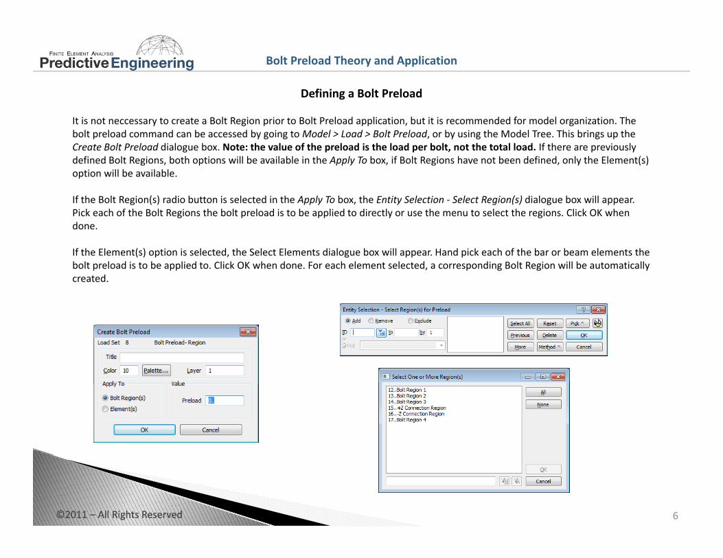
It is not neccessary to create a Bolt Region prior to Bolt Preload application, but it is recommended for model organization. The bolt preload command can be accessed by going to Model > Load > Bolt Preload, or by using the Model Tree. This brings up the Create Bolt Preload dialogue box. Note: the value of the preload is the load per bolt, not the total load. If there are previously defined Bolt Regions, both options will be available in the Apply To box, if Bolt Regions have not been defined, only the Element(s) option will be availableoption will be available.
If the Bolt Region(s) radio button is selected in the Apply To box, the Entity Selection ‐ Select Region(s) dialogue box will appear. Pick each of the Bolt Regions the bolt preload is to be applied to directly or use the menu to select the regions. Click OK whendone.
If the Element(s) option is selected, the Select Elements dialogue box will appear. Hand pick each of the bar or beam elements the bolt preload is to be applied to. Click OK when done. For each element selected, a corresponding Bolt Region will be automatically created.
©2011 – All Rights Reserved 6©2011 – All Rights Reserved
Bolt Preload Theory and Application
Contact Regions
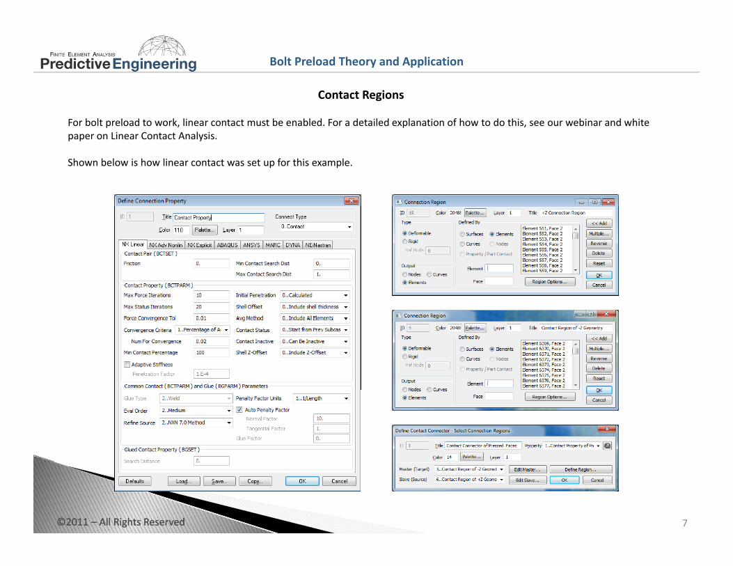
For bolt preload to work, linear contact must be enabled. For a detailed explanation of how to do this, see our webinar and white paper on Linear Contact Analysis.
Shown below is how linear contact was set up for this example.
©2011 – All Rights Reserved 7©2011 – All Rights Reserved
Bolt Preload Theory and Application
Classic Bolt Preload Example: Tension
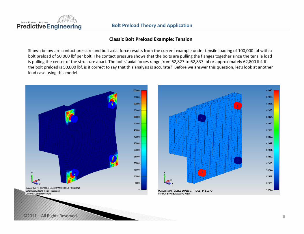
Shown below are contact pressure and bolt axial force results from the current example under tensile loading of 100,000 lbf with a bolt preload of 50,000 lbf per bolt. The contact pressure shows that the bolts are pulling the flanges together since the tensile load is pulling the center of the structure apart. The bolts’ axial forces range from 62,827 to 62,837 lbf or approximately 62,800 lbf. If the bolt preload is 50,000 lbf, is it correct to say that this analysis is accurate? Before we answer this question, let’s look at another load case using this modelload case using this model.
©2011 – All Rights Reserved 8©2011 – All Rights Reserved
Bolt Preload Theory and Application
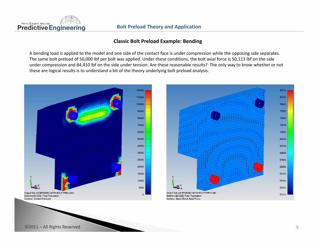
Classic Bolt Preload Example: Bending
A bending load is applied to the model and one side of the contact face is under compression while the opposing side separates. The same bolt preload of 50,000 lbf per bolt was applied. Under these conditions, the bolt axial force is 50,113 lbf on the sideunder compression and 84,410 lbf on the side under tension. Are these reasonable results? The only way to know whether or not these are logical results is to understand a bit of the theory underlying bolt preload analysis.
©2011 – All Rights Reserved 9©2011 – All Rights Reserved
Bolt Preload Theory and Application
Idealization of Bolt Preloads
Bolt preload can be idealized as: (Mechanical Engineering Design, Shigley, 3rd Ed, 1977)
l db lFb lfi llF
FkkPkF isb
bb +
+=
*
stiffnessstructurekstiffnessboltkloadappliedexternallyPpreloadboltFboltonforceaxialtotalF
sb
ib
=====
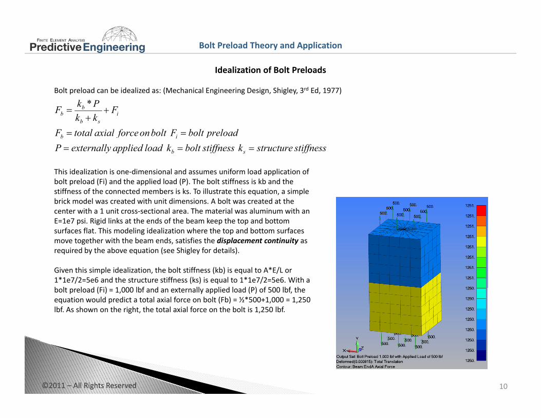
This idealization is one‐dimensional and assumes uniform load application of bolt preload (Fi) and the applied load (P) The bolt stiffness is kb and thebolt preload (Fi) and the applied load (P). The bolt stiffness is kb and the stiffness of the connected members is ks. To illustrate this equation, a simple brick model was created with unit dimensions. A bolt was created at the center with a 1 unit cross‐sectional area. The material was aluminum with an E=1e7 psi. Rigid links at the ends of the beam keep the top and bottom surfaces flat. This modeling idealization where the top and bottom surfaces move together with the beam ends, satisfies the displacement continuity as required by the above equation (see Shigley for details).
Given this simple idealization, the bolt stiffness (kb) is equal to A*E/L or 1*1e7/2=5e6 and the structure stiffness (ks) is equal to 1*1e7/2=5e6. With a b lt l d (Fi) 1 000 lbf d t ll li d l d (P) f 500 lbf thbolt preload (Fi) = 1,000 lbf and an externally applied load (P) of 500 lbf, the equation would predict a total axial force on bolt (Fb) = ½*500+1,000 = 1,250 lbf. As shown on the right, the total axial force on the bolt is 1,250 lbf.
©2011 – All Rights Reserved 10©2011 – All Rights Reserved

Bolt Preload Theory and Application
Idealization of Bolt Preloads
The prior equation is valid as long as compression exists between the preloaded parts. If the external load causes the preloadedparts to separate, then the total external load is carried only by the bolt. This tipping point can be calculated using the following equation from Shigley:
partspreloadedbetweenforceFFkkPkF si
ss =−
+=
*
If the bolt preload (Fi) is 1,000 lbf, then the clamped parts would separate when Fs=0.0. The above equation can then be rearranged and the external load to negate the preload would be:
kk sb +
000,22000,1 =•=+
•= PkkFP sbi
In general terms, if your bolt preload is equal or greater than the externally applied load, then the preloaded parts will stay clamped and facilitate the joint staying “locked”.
000,22000,1Pk
FPs
i
j y g
From a fatigue viewpoint, the importance of a preloaded joint cannot be overstated due to lower alternating stresses in the bolt and that the joint stays locked. A fatigue discussion is given at the end of this white paper.
©2011 – All Rights Reserved 11©2011 – All Rights Reserved
Bolt Preload Theory and Application
Bolt Preloads with Plate models
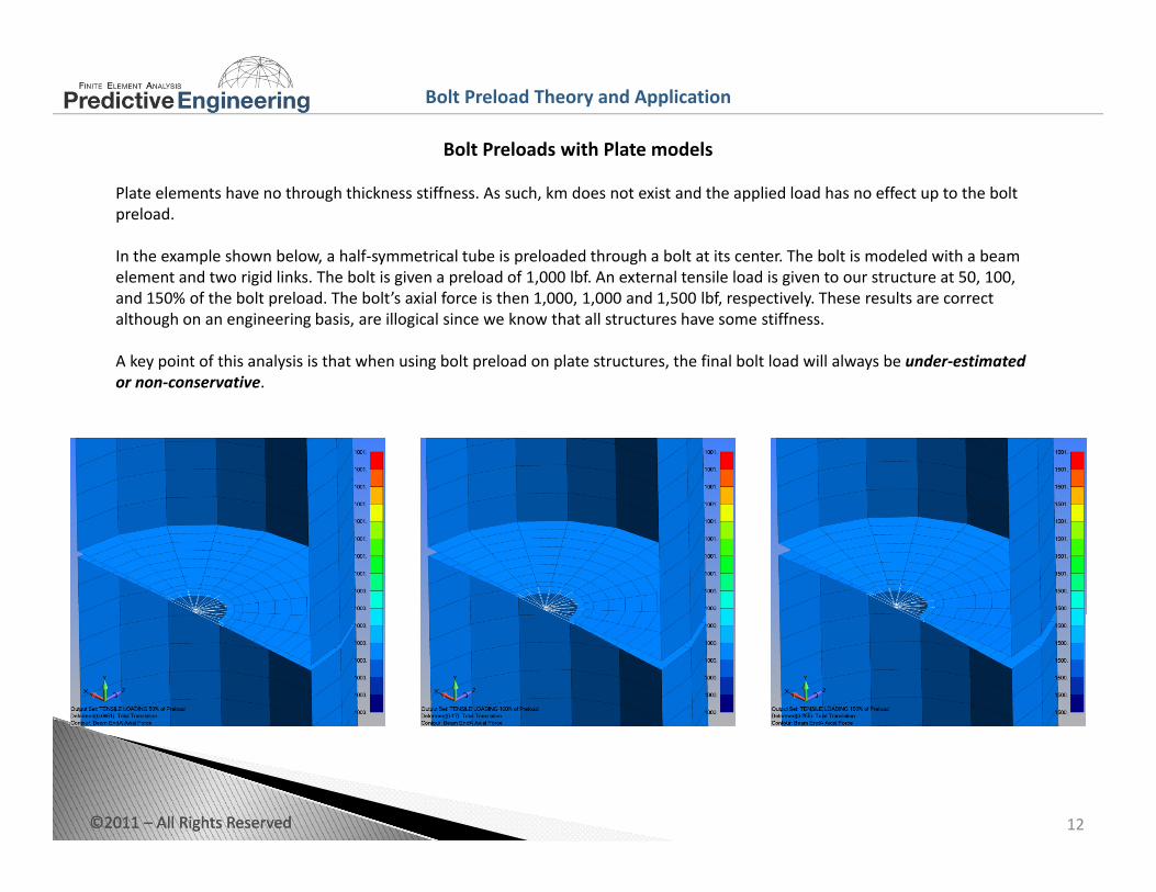
Plate elements have no through thickness stiffness. As such, km does not exist and the applied load has no effect up to the boltpreload.
In the example shown below, a half‐symmetrical tube is preloaded through a bolt at its center. The bolt is modeled with a beam element and two rigid links The bolt is given a preload of 1 000 lbf An external tensile load is given to our structure at 50 100element and two rigid links. The bolt is given a preload of 1,000 lbf. An external tensile load is given to our structure at 50, 100, and 150% of the bolt preload. The bolt’s axial force is then 1,000, 1,000 and 1,500 lbf, respectively. These results are correct although on an engineering basis, are illogical since we know that all structures have some stiffness.
A key point of this analysis is that when using bolt preload on plate structures, the final bolt load will always be under‐estimated or non‐conservative.
©2011 – All Rights Reserved 12©2011 – All Rights Reserved
Bolt Preload Theory and Application
Bolt Preloads in Solid Models
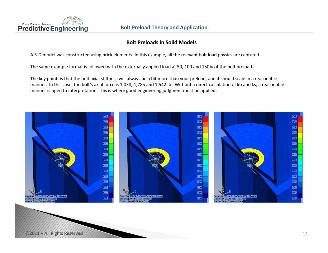
A 3‐D model was constructed using brick elements. In this example, all the relevant bolt load physics are captured.
The same example format is followed with the externally applied load at 50, 100 and 150% of the bolt preload.
The key point is that the bolt axial stiffness will always be a bit more than your preload and it should scale in a reasonableThe key point, is that the bolt axial stiffness will always be a bit more than your preload, and it should scale in a reasonablemanner. In this case, the bolt’s axial force is 1,038, 1,285 and 1,542 lbf. Without a direct calculation of kb and ks, a reasonable manner is open to interpretation. This is where good engineering judgment must be applied.
©2011 – All Rights Reserved 13©2011 – All Rights Reserved
Bolt Preload Theory and Application
Summary of Bolt Preload Theory, Application and Fatigue
Bolt preload theory states:
isb
bb F
kkPkF +
+=
*
And assumes that the bolt preload and the external load act on the same section of solid material. The final axial force on apreloaded bolt (Fb) will be the bolt preload and then some fraction of the externally applied load.
In plate models ks is infinite (it really doesn’t exist since it is a plate). Hence, the applied load does not increase the bolt load
sb
In plate models ks is infinite (it really doesn t exist since it is a plate). Hence, the applied load does not increase the bolt load (Fb) until P exceeds Fi. This under predicts the actual bolt load since all bolted structures have some bolted joint stiffness (km).
In a solid model, bolt preload functions as one would expect and the total bolt axial force follows bolt theory in general terms. However, care should be taken in how the bolt head and nut are modeled with rigid links since the bolt preload mechanism requires that the structural members be compressed underneath the bolt head or nut for bolt preload to function as desired.
©2011 – All Rights Reserved 14©2011 – All Rights Reserved

Bolt Preload Theory and Application
Summary of Bolt Preload Theory, Application and Fatigue
One of the main reasons for applying bolt preload is to avoid fatigue of the bolt. This may not seem immediately obvious after the prior discussion since it was shown that the final bolt load is always higher than the initial bolt preload. That is, the bolt stress is a linear combination of the bolt preload and some fraction of the externally applied load. But, the bolt’s alternatingstress is greatly reduced. This is the dominant advantage of bolt preload.
Let’s consider two fatigue cases and evaluate bolt life using the Soderberg equation for simplicity where:
StressMeanStresseAlternativSyS
ma
m
e
a
==
=+
σσ
σσ 1
In this example, we’ll assume that any external load increases the bolt preload by 20% (see theory section). Here are the parameters:Bolt Area = 1 sq inBolt Preload = 80,000 lbfAlternating Stress (Externally Applied Load = 100,000 lbf that cycles from 0.0).Bolt Stress Endurance (Se) = 70,000 psiBolt Yield Stress (Sy) = 140,000 psi
The question that is posed is does bolt preload help or hurt?No Bolt Preload:
F il01071000,50000,50>+
With Bolt Preload:
Fails0.107.1000,140,
000,70,
>=+
Passes
FF bb
01790000,90000,10000,100000,80000,100*2.0
<=+
=+=
©2011 – All Rights Reserved
Passes0.179.0000,140000,70
<=+
15©2011 – All Rights Reserved