Embed Size (px)
Citation preview
16 APRIL 2010
AIR NATIONAL GUARD
DESIGN OBJECTIVES AND PROCEDURES
(TAB C)
AIR NATIONAL GUARD
DESIGN OBJECTIVES AND PROCEDURES
INDEX
SECTION SUBJECT PAGE
PURPOSE 3-4
1 DESIGN OBJECTIVES 5-7
2 AUTHORITIES AND RESPONSIBILITIES 8-9
3 ARCHITECTURAL ENGINEERING SCOPE OF SERVICES 10-25
4 DESIGN REVIEW PROCESS 26-28
5 DESIGN REVIEW DOCUMENTS DISTRIBUTION 29-32
ATTACHMENT 1 A-E PREPARED BASIS OF DESIGN 33-38
ATTACHMENT 2 DESIGN SCHEDULE 39
ATTACHMENT 3 ADDENDUM 40
ATTACHMENT 4 TYPE A-1 CERTIFICATION 41
ATTACHMENT 5 TYPE A-2 CERTIFICATION 42
ATTACHMENT 6 TYPE B-1 CERTIFICATION 43
ATTACHMENT 7 TYPE B-2 CERTIFICATION 44
ATTACHMENT 8 TYPE A-1 CONCEPT PROPOSAL MEETING CHECKLIST 45
ATTACHMENT 9 TYPE A-2 CONCEPT DEVELOPMENT DESIGN 46
SUBMITTAL CHECKLIST
ATTACHMENT 10 TYPE B-1 CONTRACT DOCUMENTS DEVELOPMENT 47
MEETING CHECKLIST
ATTACHMENT 11 TYPE B-2 PREFINAL DESIGN SUBMITTAL CHECKLIST 48
ANG Design Objectives and Procedures (Tab C) 16 APR 10 2
SECTION SUBJECT PAGE
ATTACHMENT 12 TYPE B-3 FINAL DESIGN SUBMITTAL CHECKLIST 49
ATTACHMENT 13 COST ESTIMATE EXECUTIVE SUMMARY FORMAT 50
ATTACHMENT 14 DD FORM 1354 SAMPLE WORKSHEET 51-55
ATTACHMENT 15 SAMPLE ROOM DATA SHEET 56
3 ANG Design Objectives and Procedures (Tab C) 16 APR 10
PURPOSE
The Air National Guard (ANG) Design Objectives and Procedures (Tab C), developed by
NGB/A7O, is established to define the overall objectives in accomplishing the ANG facilities
program and the procedures to be followed in achieving that end. It is intended that this
document be referenced and made a part of any A-E contract for the development of design
documents for ANG projects as well as for A-E services to provide post construction award
oversight and assistance service. This document may be modified to suit particular project needs
in coordination with the NGB/A7O Project Manager (PM.)
PROCESS OUTLINE
Below is an outline of the process generally followed on Military Construction Program (MCP)
projects as well as larger Sustainment, Restoration and Modernization (SRM) projects.
However, each individual project may have less complex requirements requiring a somewhat
abbreviated process. This is particularly true for smaller SRM projects. The PM, working with
the Base Civil Engineer will determine the appropriate process to follow for each individual
project and the applicable provisions of Tab C will be amended accordingly, initially in the
Project Design Instruction issued to the base by the PM and further in an Addendum (see
Attachment 3) prepared at a project Criteria Review Conference (CRC), attended by the A-E and
ANG personnel.
• Programming Phase
– Develop need for project
– Resolve Real Estate and Environmental Issues
– Develop DD Form 1391
– Program Project into Budget
• Design Phase
– Contract for A-E Services
– Type A Services
• Develop Basis of Design, Part I, Design Intent
• Develop Project Concept
• Perform Site Investigations
• Perform Formal Value Engineer Study, if required
– Type B Services
• Develop Basis of Design, Part II, Design Narrative
• Develop Construction Documents
• Perform Design Commissioning Services
• Procurement Phase
– Select Contractor
– Award Construction Contract
• Construction Phase
– Construct Project
– Type C Services
• Submittal review

ANG Design Objectives and Procedures (Tab C) 16 APR 10 4
• Quality Assurance Inspection
• Perform Construction Commissioning Services
– Accept Facility
– Project Closeout
– Resolve Warrantee Issues
5 ANG Design Objectives and Procedures (Tab C) 16 APR 10
SECTION 1 – DESIGN OBJECTIVES
1.1 Facility Goals
1.1.1. The main goal of the ANG design and construction process is to provide a complete
and usable facility that satisfies the Mission requirements with architecturally pleasing, yet
fiscally responsible construction.
1.1.2. Facility designs shall avoid the appearance of waste or excessive cost. Architectural
style and detail shall be based on sound facility design principles, while maximizing
flexibility to meet future mission needs.
1.1.3. Facility designs shall comply with the current ANG Sustainable Design and Energy
Conservation Strategies Engineering Technical Letter (ETL), and shall provide a low life
cycle cost, energy efficient facility, that requires minimal amount of maintenance. For
projects required to be certified with the USGBC, the A-E shall provide a qualified
Commissioning Agent (CA), independent from the project design firm and approved by the
Contracting Officer, during design and construction.
1.2. Project Scope - The project scope is defined as the maximum gross square footage, or
specified quantity if the scope is defined in terms other than square footage, of the facility and
shall be calculated in accordance with the Air National Guard Design Policy ANGETL (TAB D.)
The project scope is indicated on the DD Form 1391 which is part of the Project Approval
Package. This package will be provided to the A-E at the CRC. The project primary facility
scope, as indicated for each line item in Block 9 of the DD Form 1391, shall not be exceeded
without NGB/A7O approval. Furthermore, for MILCON projects, Title 10 US Code § 2853,
prohibits the facility design and construction from exceeding the established project scope as
shown on the approved DD Form 1391.
1.3. Cost of Construction
1.3.1. Maximum Construction Cost Limitation (MCC.) The MCC is defined as the set dollar
limitation that the project bid/offer price shall not exceed. The MCC will be provided to the
A-E at the CRC. The MCC is established by NGB/A7O and provided to the BCE in the
project Design Instruction (DI) letter. The A-E is required under the FAR Clause 52.236-22
– “Design Within Funding Limitations” to design the project, including all additive bid items
and options, whether awarded or not, so that the project may be constructed within the
established MCC dollar limitation. This amount does not include any allowance for change
orders or contract modifications, or for other items to be purchased with construction funds
separate from the instant contract. The A-E is responsible to deliver a design that does not
exceed the MCC in accordance with the requirements set below:
1.3.1.1. Additive Bid Items (ABIs) or Options are items of work that are not absolutely
necessary to provide a complete and usable facility, yet are authorized for the facility. .
Each ABI or Option may consist of several components. For example, one ABI may
ANG Design Objectives and Procedures (Tab C) 16 APR 10 6
consist of vinyl wall covering, ceramic tile, and window blinds, another may consist of
landscaping, irrigation systems and parking lot pavement, and a third may consist of all
casework, including cabinetry, marker boards and projection screens. ABIs or Options
shall amount to approximately ten percent (10%) of the MCC (base bid construction cost
+ ABIs or Options = MCC.) During the Concept Proposal Meeting, the Design Working
Group shall assist the A-E in the development of a reasonable number of ABI's or Option
items. ABI’s or Options shall be approved by NGB/A7O and the Contracting Officer for
each specific project. All MCP projects will use ABIs or Options to ensure that the basic
project can be awarded if construction prices are higher than anticipated, yet allows the
Government to award those items that are needed for the project, yet are not absolutely
essential, if the prices are as anticipated. SRM projects will generally not have ABIs or
Options since the intent of an SRM project is to fully address the minimum requirements
programmed and since reprogramming, if necessary, can usually be more readily
accomplished for an SRM project than for an MCP project.
1.3.1.2. Use of ABIs: ABIs must be awarded at the time of contract award. They must be
listed in the order in which they are intended to be awarded based on the funds available
at the time of the bid opening or negotiation.
1.3.1.3. Use of Options: Options are for items that the Government may not choose to
execute or have funds to cover at initial contract award, but which may be awarded if
during the prescribed execution period funds become available or the Government
chooses to execute the option. In a solicitation containing options, the latest date that the
Government may unilaterally exercise the option must be established. Options carry risk
to the contract. In evaluating the low bidder or an offeror’s price, the Contracting Officer
must evaluate inclusive of all options, whether the options are executed or not.
1.3.2. Construction cost estimates shall be provided in accordance with UFC 3-701-xx, the
Historical Air Force Construction Cost Handbook (latest version.) Parametric Cost
Engineering System (PACES) may be used for estimates at the Type A1 and A2 level, but
will have to be transferred into Micro-Computer Aided Cost Estimating System (MCACES)
for printing. Estimates at the Type B level shall be performed in MCACES format. An
executive cost summary sheet shall be prepared by the A-E as shown in Attachment 13.
Regardless of the estimating system used or the source of the pricing data the A-E is
ultimately responsible for the accuracy of the cost estimates used on the project. No
information pertaining to all such estimates shall be disclosed by the A-E, their associates,
subcontractors, or any of their employees except to the extent permitted by the Contracting
Officer.
1.3.3. Construction cost estimates shall be adjusted based on the expected date the project
will be solicited. This estimated date shall be established at the Criteria Review Conference
based on the A-E’s estimate of construction duration.
1.3.4. The A-E shall be required to show at each design submittal stage, that the facility as
designed can be constructed within the MCC limit for the project. In the event that the A-E

7 ANG Design Objectives and Procedures (Tab C) 16 APR 10
finds the MCC to be insufficient the A-E shall immediately notify the Contracting Officer in
accordance with FAR Clause 52.236-22, “Design Within Funding Limitations” and the
Contracting Officer's Technical Representative (COTR), and present those areas where cost
reduction can be made without adversely affecting the facility requirements. In no instance
shall the A-E develop a design that is less than the project's authorized scope due to cost
considerations without written authorization from NGB/A7O and direction from the
Contracting Officer.
ANG Design Objectives and Procedures (Tab C) 16 APR 10 8
2. SECTION 2 – AUTHORITIES AND RESPONSIBILITIES
2.1. Contracting. The Contracting Officer is the only individual who has the authority to
negotiate, enter into or modify contracts, or to obligate Federal funds on a contract. While the
Contracting Officer may designate a Contracting Officer’s Technical Representative (COTR),
usually the Base Civil Engineer (BCE), who is given limited authority, as defined in his
appointment letter, to communicate with the A-E and construction contractor. The Contracting
Officer is the only individual who may modify any provision of the contract. If the A-E
proceeds with the design or any changes to the design without the express authority of the
Contracting Officer, they shall do so at their own risk.
2.2. Design Management
2.2.1. The Operations Division (NGB/A7O) of the Installations and Mission Support
Directorate, Air National Guard Readiness Center, located at Andrews Air Force Base, MD,
provides management oversight and approval of construction projects, including criteria,
designs and project funding. NGB/A7O is the only office with authority to change or clarify
design criteria. NGB/A7O is the approval authority for all submittals that are required to be
submitted to NGB/A7O and they will compile and edit all other comments submitted by the
base and NGB/A7OC. NGB/A7O does NOT have the authority to direct changes to the
contract. If the A-E feels that any direction given by NGB/A7O is a change in contract
requirements, the A-E shall immediately notify the Contracting Officer and NGB/A7O prior
to taking any action.
2.2.2. The Civil Engineering Technical Services Center (CETSC), NGB/A7OC, is located in
Minot, ND, which will provide project review support to the BCE as needed. NGB/A7OC
has engineers in all major disciplines and technicians involved in specialty areas, including
aircraft arresting systems, petroleum, oils & lubricants (POL) facilities, airfield pavements
and High Expansion Foam fire suppression systems. Some projects require these specialized
reviews as directed by NGB/A7O and specified in the contract. These minimum
requirements are noted in Section 5.5. Additionally, other projects may require these reviews
and will be established at the Criteria Review Conference by the Contracting Officer and
specified in the contract. All NGB/A7OC review comments will be forwarded to the A-E via
the BCE and Contracting Officer. NGB/A7OC does not have the authority to direct changes
to the contract. If the A-E feels that any direction given by NGB/A7OC is a change in
contract requirements, the A-E shall immediately notify the Contracting Officer and
NGB/A7O prior to taking any action.
2.2.3. The BCE is the Government’s local engineering management coordinator and usually
serves as the COTR on the A-E contract. The BCE is responsible for furnishing existing
information of on-site conditions, including Environmental Restoration Program (ERP) sites,
utility locations, etc. and is the point of contact for the A-E to meet with other base offices.
The BCE shall function as the single point of contact for all design review comments for the
A-E on submittals not required to be submitted to NGB/A7O. The BCE will compile, edit
and submit, including NGB/A7OC comments and include these with all submittals required
9 ANG Design Objectives and Procedures (Tab C) 16 APR 10
to be reviewed by NGB/A7O. The BCE does not have the authority to change design criteria
or to direct changes to the contract. If the A-E thinks that any direction given by the BCE is
a change in contract requirements, the A-E shall immediately notify the Contracting Officer
prior to taking any action.
2.2.4. The base using activity (user) will be the occupant of the facility being designed. The
user, in coordination with the BCE, is responsible for providing the A-E with information on
its operations and on special or unique equipment that will be in the facility. The user does
not have the authority to change design criteria or to direct changes to the contract. If
information supplied by the user appears to conflict with criteria provided in the contract, the
A-E shall immediately notify the Contracting Officer and BCE prior to taking any action.
2.2.5. The Design Working Group (DWG) is the bases team responsible for developing
requirements and desires for the intended project. The BCE serves as the DWG's
chairperson. Representatives of the user(s) shall be assigned to the DWG for the duration of
the project and should be available for all meetings, reviews and other design activities.
Representatives of the user must have delegated authority to speak for the using activity with
respect to all requirements. Other necessary base personnel representing functional areas of
expertise, including fire, safety, force protection, environmental and communications all
must be part of the delegated DWG team. The DWG is initially formed to develop the
Government’s project requirements. The same DWG should be retained and delegated to
work with the A-E's design team and provide information and guidance throughout the
development of the Basis of Design and project design process. The DWG will meet with
the A-E's design team as needed. The DWG does not have the authority to change design
criteria or to direct changes to the contract. If the A-E thinks that any direction given by the
DWG is a change in contract requirements, the A-E shall immediately notify the Contracting
Officer prior to taking any action.
ANG Design Objectives and Procedures (Tab C) 16 APR 10 10
3. SECTION 3 – ARCHITECTURAL-ENGINEERING (A-E) SERVICES
3.1. Overview of the Design Process. NGB/A7O initiates the design project by authorizing the
BCE to procure A-E services through the Contracting Officer for the project. The NGB/A7O
PM will issue a Design Instruction establishing the project cost and scope and outlining the
required A-E services for the project. Once an A-E has been selected the BCE and Contracting
Officer will conduct a CRC with the selected A-E. The NGB/A7O PM may attend the CRC.
Attachment 3 provides a CRC Addendum sheet to be used to track changes to Tab C defined at
the CRC. This should be used along with the Checklist of A-E Services Requirements provided
to the base with the Design Instruction to establish the scope of A-E services to be provided. At
the CRC the Government will review the project scope and budget. The Government will define
the level of services required from the A-E. The A-E will also be presented any available
Government project information. Further, the Government will review in detail procedures to
follow in the contract as well as all submittal requirements from the A-E. At the close of the
CRC the A-E will be presented a Request for Proposal for the A-E services. Following A-E fee
negotiations, legal review of the contract documents and award of the signed Contract, the design
shall proceed along the following steps:
3.1.1. A-E issued Notice to Proceed (NTP) to Type A.
3.1.2. A-E prepares Part I of the Basis of Design, if required (see Attachment 1) and submits
to BCE for approval prior to proceeding further with design.
3.1.3. Type A-1 Concept preparation and Type A-1 Concept Proposal Meeting; review and
approval by the DWG.
3.1.4. Prepare with BCE approval a Type A-1 Certification form (see Attachment 4) to be
submitted to NGB/A7O, along with a copy of the Approved Part I of the Basis of Design (see
Attachment 1). This is generally for NGB/A7O awareness only and does involve a stop in
the design process unless funding is only available for Type A-1 Concept Proposal services.
In such case, the A-E will be notified of this at the CRC and there will be a DESIGN STOP
pending NGB/A7O notification of the availability of additional funding and direction to
proceed from the Contracting Officer (If project design will not proceed at this point the
Contracting Officer will notify A-E within 28 days of submittal.)
3.1.5. Type A-2 Concept preparation and Type A-2 Concept Development Meeting with the
DWG.
3.1.6. Prepare with BCE approval a Type A-2 Certification form (see Attachment 5) to be
submitted with the Type A-2 Concept Development Submittal.
3.1.7. Type A-2 Concept Development Submittal with incorporated base comments;
DESIGN STOP, await approval by NGB/A7O and direction to proceed from the Contracting
Officer (If project design will not proceed at this point the Contracting Officer will notify A-
E within 28 days of submittal.)
3.1.8. Perform Optional Value Engineering Service, if required in the contract and Notice to
proceed is issued by the Contracting Officer.
3.1.9. A-E issued NTP to Design (Type B) Services.
3.1.10. Develop Contract Documents to the B-1 level and hold Contract Document
Development Meeting with the DWG (Type B-1).
11 ANG Design Objectives and Procedures (Tab C) 16 APR 10
3.1.11. Prepare with BCE approval a Type B-1 Certification form (see Attachment 6) to be
submitted to NGB/A7O. This is for NGB/A7O awareness and does involve a stop in the
design process.
3.1.12. Forward B-I submittal to NGB/A7OC if required by the contract. (See 3.3.2.)
3.1.13. NGB/A7OC review comments are sent to the BCE. BCE reviews comments for
consistency with other direction given A-E and forwards comments to Contracting Officer
who in turn forwards them to A-E.
3.1.14. Develop Contract documents to the Type B-2 level and prepare with BCE approval a
Type B-2 Certification form (see Attachment 7) to be submitted to NGB/A7O with the Type
B-2 Prefinal Submittal.
3.1.15. Type B-2 Prefinal Submittal with incorporated base comments; DESIGN STOP,
await approval of NGB/A7O and direction from the Contracting Officer.
3.1.16. A-E issued approval to proceed to Final Design (Type B-3) Services.
3.1.17. Make any final adjustments to the design as required by the Contracting Officer and
make Final Submittal (Type B-3), design complete.
3.1.18. Code and Criteria Review if required.
3.1.19. Perform Optional Contract Procurement services if required by the contract and NTP
is given by the Contracting Officer.
3.1.20. Reproduction of Bid Documents, if required.
3.1.21. Construction Inspection and Testing (Type C) Services, if included in contract.
3.2. Investigative Services (Type A)
3.2.1. Type A-1 Concept Proposal: A-E shall furnish the following:
3.2.1.1. Basis of Design: If included in the A-E contract the A-E, working with the
DWG, shall prepare the Basis of Design, Part I-Design Intent, as described in Attachment
1. The level of detail of the information provided to the A-E to begin the preparation of
the Basis of Design phase may vary widely depending on available program information
and local Civil Engineer resources. This document shall be completed and approved by
the BCE prior to the A-E proceeding to development of the Concept Proposal.
3.2.1.2. Type A-1 Concept Proposal Development and Type A-1 Concept Proposal
Meeting: Based on the approved Basis of Design, Part I-Design Intent, and other project
information, the A-E shall develop several project concept proposals as required below.
The A-E shall then meet with the DWG for the purpose of selecting from several
conceptual schemes, a single scheme to investigate further, and perform the following:
3.2.1.2.1. Provide a minimum of three single line site sketches (as site allows – 1
primary and 2 alternates, may be free hand) to scale. Site sketches will be based on
the A-E's site analysis, and shall indicate, as a minimum, contours, prevailing winds,
pedestrian and vehicular circulation, facility layout and orientation, relationship to
adjacent facilities, Environmental Restoration Program (ERP) sites, airfield clearances
as appropriate, Explosive Quantity Distances as appropriate, and all other setback or
clearance requirements affecting the facility. One site sketch shall accompany each of
ANG Design Objectives and Procedures (Tab C) 16 APR 10 12
the floor plan sketches referenced in Para. 3.2.1.2.2. The site sketch shall be shown
over existing topographic map if locally available. A separate sketch for each site will
provide the details showing the application of the Antiterrorism and Force Protection
(ATFP) requirements.
3.2.1.2.2. Provide a minimum of three single line floor plan sketches (as program
allows – 1 primary and 2 alternates, may be free hand) drawn to scale reflecting the
spatial relationships as required. Indicate on each sketch each floor space name, net
area provided in each floor space, approximate dimensions of each floor space, and
indicate the gross building area (not to exceed the project scope).
NGB/A7O PM through the Contracting Officer may waive the requirement for three
site sketches or the requirement for three floor plans in some projects.
(NOTE: For projects with floor plan areas containing at least 1,000 square feet of
contiguous administrative area, the A-E shall provide for generic layout of pre-wired
workstations per ANG Design Policy ETL, Section "Architectural." The layout shall
show the number of workstations each area can support.)
3.2.1.2.3. Provide a building section based on the proposed primary site plan and floor
plan.
3.2.1.2.4. Provide a narrative description of each of the proposed building systems to
include the following:
A - Substructure;
B - Shell;
C - Interior;
D - Services;
E - Equipment and Furnishings;
F - Special Construction and Demolition
G - Building Sitework
Z - General
3.2.1.2.5. Provide a construction cost estimate in accordance with 1.3.2., showing
details and subtotals for each major element shown above and a grand total for the
project. Provide a listing of ABIs or Options. Cost estimate will detail base plus
ABI’s or Options. ABI’s or Options will total a minimum of 10% of the total MCC.
Base cost will total a maximum of 90% of the MCC. No information pertaining to
all such estimates shall be disclosed by the A-E, their associates, subcontractors, or
any of their employees except to the extent permitted by the Contracting Officer.
3.2.1.2.6. A-E prepares ANG Sustainable Design and Energy Conservation Score
Sheet, identifying anticipated points, for all three concepts presented at the Type A-1
Concept Proposal meeting.
13 ANG Design Objectives and Procedures (Tab C) 16 APR 10
3.2.1.2.7. During Type A-1 services, the A-E shall initiate the following services as
may be required to further develop the conceptual design and in support of Type A-2
and Type B services:
Topographic surveys
Aerial surveys
Utility services, including hydrant flow tests
Cathodic protection services
Soil borings, test reports and analysis
Environmental analysis
Other fact-finding investigations, such as, determination of permitting
requirements, clarifying user requirements, economic feasibility studies, value
engineering proposals, etc.
3.2.1.3. A-E prepares with BCE a Type A-1 Certification form to be submitted to
NGB/A7O (see Attachment 4). Type A-1 Certification form provides NGB/A7O with
confirmation that the Type A-1 submittal meets all budget and scope requirements
without further reprogramming or cost cutting. The BCE then submits the Type A-1
Certification to NGB/A7O.
3.2.1.3.1 See Attachment 8 for Type A-1 Concept Development Meeting Checklist.
This checklist is completed by the A-E and included with the submittal. The BCE
then reviews the submittal against the completed checklist to insure completeness of
the submittal.
3.2.2. Type A-2 Concept Development
3.2.2.1. Type A-2 Concept Development Meeting The A-E shall meet with the DWG
for the purpose of presenting further investigative development of the selected concept,
and perform the following:
3.2.2.1.1. Provide a refined conceptual site plan sketch and floor plan sketch. Include
a scope calculation (not to exceed the project scope). Site plan sketch shall indicate,
as a minimum, the building orientation, pavements, landscaping, utility runs, contours,
etc. Floor plan sketch shall indicate, as a minimum, layout of rooms, space
dimensions, door and window locations, user equipment, and fixed equipment (i.e.,
toilets, lavatories, theater seating, etc.)
3.2.2.1.2. Perform a value engineering analysis of the project building systems
proposed in the Concept Proposal considering alternative project building systems.
(This is separate from the Formal Value Engineering study, if authorized and
described later). Provide an analysis of alternative project building systems in
accordance with the requirements given in ANG Design Policy ETL, Section
"Economic Analysis." Discuss the alternative buildings systems considered and the
ANG Design Objectives and Procedures (Tab C) 16 APR 10 14
basis for the A-E’s recommended system. Summarize the economic advantages of
each system that is recommended in lieu of the system identified in the Type A-1
Concept Proposal. Include the following:
Wall and roof systems analyzed and the recommended systems;
Building elevation sketches using recommended architectural system;
Structural systems analyzed and the recommended system;
Mechanical systems analyzed and the recommended system;
Electrical systems analyzed and the recommended system;
3.2.2.1.3. Provide a complete design analysis of all required fire systems (detection
and suppression) including all requirements identified in ANG Design Policy ETL
(Tab D) and UFC 3-600-01. Verify fire flow capacities of water supply in the vicinity
of the project site per the UFC requirements.
3.2.2.1.4. Provide a complete analysis of all applicable ATFP provisions for this
project according to the building occupancy classification in compliance with UFC 4-
010-01.
3.2.2.1.5. Investigate and report on any permit applications that should be filed for the
project to be in compliance with any federal, state, and local requirement on the
management of air, water and waste.
3.2.2.1.6. Develop and provide a construction cost estimate (using budgetary
parametric estimating tools), in accordance with 1.3.2., showing subtotals for each
division and a grand total for the project. Provide a listing of ABIs or Options. Cost
estimate will detail base plus ABI’s or Options. ABI’s/Options will total a minimum
of 10% of the total MCC. Base cost will total a maximum of 90% of the MCC. No
information pertaining to all such estimates shall be disclosed by the A-E, their
associates, subcontractors, or any of their employees except to the extent permitted
by the Contracting Officer.
3.2.2.1.7. Provide a black and white perspective sketch or drawing to show proposed
major design features of the facility. NGB/A7O PM, through the Contracting Officer,
may waive this requirement.
3.2.2.1.8. Complete and provide ANG Sustainable Design and Energy Conservation
Score Sheet and Narrative. Also, complete and provide preliminary energy modeling
summary results in the Energy Conservation section of the score sheet.
3.2.2.2. Type A-2 Concept Submittal. Within 7 calendar days following the A-E's
Concept Development Meeting with the DWG, the A-E shall incorporate
recommendations of the DWG and submit all the required items listed below to each
office listed in Section 5, Design Review Documents Distribution.
15 ANG Design Objectives and Procedures (Tab C) 16 APR 10
3.2.2.2.1. Provide a separately bound Basis of Design. Included shall be Part I,
Design Intent, as approved earlier and Part II, Design Narrative, a documentation of
the primary thought processes and assumptions behind design decisions that were
made to meet the design intent. See Attachment 1 for a description of Basis of Design.
The Basis of Design, Part II, Design Narrative, describes the systems, components,
conditions and methods chosen to meet the intent. Some reiterating of the design
intent may be included. Include expansions on the statements given in Part I, Design
Intent, and additional information collected from the A-E's fact finding investigations
with the Users. Include as part of Part II, Design Narrative, Room Data Sheets,
similar to those presented in Part I, Design Intent, describing each room of the facility
and include details as to what is being included in each space and how the
requirements defined in Part I, Design Intent are being met.
3.2.2.2.2. Provide soil boring logs, analyses and test reports, and the results of any
other surveys or investigations required under Para. 3.2.1.2.7.
3.2.2.2.3. Provide the selected building features, components and systems to include
the following:
Site plan sketch (Building Orientation, Pavements, Utilities, Contours/Drainage)
Landscape plan sketch;
Floor plan sketch;
Building elevations;
Building sections;
Scope calculations, showing total building scope and net-to-gross area percentage;
Narrative description of each building system (to be included in Part II, Design
Narrative of the Basis of Design;
3.2.2.2.4. Provide a report of the Value Engineering Analysis required under Para.
3.2.2.1.2.
3.2.2.2.5. Provide report of Fire Systems Analysis required under Para. 3.2.2.1.3.
3.2.2.2.6. Provide a summary of all ATFP measures employed in the design based on
occupancy classification as required under Para. 3.2.2.1.4.
3.2.2.2.7. Provide summary of applicable permits for this project as required under
Para. 3.2.2.1.5.
3.2.2.2.8. Provide an updated construction cost estimate as required under Para.
3.2.2.1.6.
3.2.2.2.9. Provide an ANG Sustainable Design and Energy Conservation Score Sheet
and Narrative. Also, provide preliminary energy model summary results in the Energy
Conservation section of the score sheet.
ANG Design Objectives and Procedures (Tab C) 16 APR 10 16
3.2.2.2.10. Provide a Notice of the Meeting for documentation of the Type A-2
Concept Development Meeting.
3.2.2.2.11. Provide an updated project design schedule showing expected DWG
meeting dates and design submittals through Type B-3 Final Design (Attachment 2.)
3.2.2.2.12. A-E prepares with BCE a Type A-2 Certification form (see Attachment 5)
to be submitted to NGB/A7O. Type A-2 Certification form provides NGB/A7O with
confirmation that the Type A-2 submittal meets all budget and scope requirements
without further reprogramming or cost cutting.
3.2.2.2.13. Provide completed “Submittal Checklist List Type A-2 Concept”
(Attachment 9.)
3.3. Design Services (Type B) The A-E shall perform services listed below, if and when the
Contracting Officer exercises this contract option by issuing a written NTP.
3.3.1. Type B-1 Contract Documents Development Meeting (CDDM). Based on the
approved Type A services the A-E shall develop Contract Documents as required below.
The A-E shall meet with the DWG to conduct an "on-board" progress meeting at
approximately the midpoint of design services. For projects to be certified with the USGBC,
the Commissioning Agent (CA) review must be incorporated in this meeting and the Basis of
Design, drawing and specification shall be evaluated by the CA. For this meeting the A-E
shall provide the following elements.
3.3.1.1. Develop and provide complete edited draft technical division specifications in a
standard commercial format bound in a separate book and in MS Word format on a
CD.
3.3.1.2. Develop and provide a detailed construction cost estimate, including ABI's or
Options, using unit prices and quantities for all materials and labor for the project.
Include a Cost Estimate Executive Summary (Attachment 13.) Bind construction cost
estimate with the Cost Estimate Executive Summary in a separate booklet. No
information pertaining to all such estimates shall be disclosed by the A-E, their
associates, subcontractors, or any of their employees except to the extent permitted by
the Contracting Officer.
3.3.1.3. Develop and furnish all drawings in 65 percent detail for all disciplines of work.
The A-E shall provide drawings which are created using AutoCAD (computer aided
design and drafting) in most current version.
3.3.1.4. Provide an updated ANG Sustainable Design and Energy Conservation Score
Sheet and Narrative. Also, complete and provide updated energy modeling summary
results.
17 ANG Design Objectives and Procedures (Tab C) 16 APR 10
3.3.1.5. Provide the updated Basis of Design. Part 1, Design Intent as approved shall be
included as well as Part 2, Design Narrative providing information developed to the level
of the current design progress.
3.3.1.6. If authorized by ANG/A7O and included in the contract, provide two (2)
AutoCAD renderings or sketches, or freehand artist renderings or sketches from
different viewing points for selection of an exterior facility rendering.
3.3.1.7. Present for the BCE's signature, completed permit applications required for the
project to be in compliance with applicable federal, state and local air, water and waste
requirements.
3.3.1.8. Reproduce all Type A review comments with annotations describing the
disposition of each comment and the location within the contract documents where the
comment address was incorporated.
3.3.1.9. The A-E shall submit to the Contracting Officer and NGB/A7O.
A notice of the CDDM meeting with the DWG.
The construction cost estimate attaching the Cost Estimate Executive Summary
(Attachment 13.)
An updated project design schedule, noting any deviations from the contracted A-E
schedule.
Provide minutes of the CDDM, including topics discussed, Government direction
provided and a narrative summary explaining any deviation from the approved
Concept Submittal.
3.3.1.10. A-E prepares with BCE a Type B-1 Certification form to be submitted to
NGB/A7O Type B-1 Certification form provides NGB/A7O with confirmation that the
Type B-1 submittal meets all budget and scope requirements without further
reprogramming or cost cutting.
3.3.1.11. See Attachment 10 for Type B-1 CDDM Checklist. The A-E is to complete the
check list and forward to the BCE. The BCE shall review the checklist against the
information furnished at the B-1 meeting. For those projects where a formal submittal is
to be made to NGB/A7OC the completed checklist shall accompany the submittal.
3.3.2. Type B-1 Contract Document Development Submittal. (Only required if design is
required to be submitted to NGB/A7OC)
3.3.2.1. The A-E shall submit to NGB/A7OC design drawings and specifications, along
with an updated Basis of Design.
3.3.2.1.1 Furnish all drawings in 65 percent details.
ANG Design Objectives and Procedures (Tab C) 16 APR 10 18
3.3.2.1.2. Specifications shall be complete edited draft technical division
specifications in a standard commercial format bound in a separate book and in MS
Word format on a CD.
3.3.2.1.3 Basis of Design, shall be separately bound, to include Part I, Design Intent
and Part II, Design narrative updated to reflect current design status. The Basis of
Design shall be in a standard commercial format bound in a separate book and in
MS Word format on a CD.
3.3.2.2. Provide a detailed construction cost estimate, including ABI's or Options, using
unit prices and quantities for all materials and labor for the project. Include a Cost
Estimate Executive Summary (Attachment 13.) Bind construction cost estimate with the
Cost Estimate Executive Summary in a separate booklet.
3.3.3. Type B-2 Prefinal Submittal. The A-E shall submit the required items listed below to
each office listed in Section 5, Design Review Documents Distribution.
3.3.3.1. Provide a separately bound set of all engineering design calculations and
analyses for each discipline.
3.3.3.2. Provide detailed working drawings 100% complete and ready for contract
acquisition, in all disciplines of work. These should be submitted per Section 5.
3.3.3.3. Provide separately bound complete final specifications, ready for contract
acquisition, in a standard commercial format for prefinal review. Specifications shall
include Division 1, General Requirements, (coordinated with the Contracting Officer and
BCE).
3.3.3.3.1. Include in the General Provisions of the Specifications, sections providing
a Summary of Work entailed with this project, the Bid Structuring, and a
Construction Phasing Plan (If required for this project.)
3.3.3.3.2. Include a requirement in the General Provisions of the Specifications for
the construction contractor to maintain an up-to-date set of red-marked, annotated as-
built drawings to be furnished to the Government upon completion of the
construction.
3.3.3.3.3. For projects estimated to cost over $1 million, include a requirement in the
General Provisions of the Specifications for a contractor-prepared and contractor-
maintained critical path method (CPM) construction schedule using the arrow
diagramming method. State in the specifications that the CPM schedule can be used
in lieu of AF Form 3064, Contract Progress Schedule, providing a mechanism is in
place to validate percentage of completion for verifying payment vouchers. (This has
19 ANG Design Objectives and Procedures (Tab C) 16 APR 10
been coordinated with National Guard Bureau Principal Assistant Responsible for
Contracting (NGB-PARC.)
3.3.3.4. Provide a separately bound final construction cost estimate, in accordance with
1.3.2, including ABI's or Options and separate line item costs, using unit prices and
quantities for all materials and labor for the project. Include a Cost Estimate Executive
Summary (Attachment 13.) No information pertaining to all such estimates shall be
disclosed by the A-E, their associates, subcontractors, or any of their employees except
to the extent permitted by the Contracting Officer.
3.3.3.5. Provide an updated ANG Sustainable Design and Energy Conservation Score
Sheet and Narrative. Complete and provide the project energy modeling summary
results.
3.3.3.6. Provide an updated separately bound Basis of Design, Parts I and II, in both MS
Word (.doc) and Portable Document Format (.pdf). Include CA review comments, if
applicable.
3.3.3.7. If authorized by ANG/A7O and identified in the contract, provide one
professionally prepared 24” x 36” matted and framed, fully colored, perspective
rendering using an AutoCAD® generated rendering or provide same rendering
requirement using free hand artist production. Size indicated above shall be for the
rendering, required frame size and matting will be appropriately larger. Also provide
rendering information in digital format (.JPEG) or other high-resolution format on titled
CD. Provide framed rendering and digital copy on a CD to the BCE and one digital copy
only to NGB/A7O.
3.3.3.8. A-E prepares with BCE a Type B-2 Certification form (see Attachment 7) to be
submitted to NGB/A7O Type B-2 Certification form provides NGB/A7O with
confirmation that the Type B-2 submittal meets all budget and scope requirements
without further reprogramming or cost cutting.
3.3.3.9. The A-E shall complete and provide Type B-2 Prefinal Submittal checklist from
Attachment 11. The A-E is to complete the check list and forward to the BCE. The BCE
shall review the checklist against the information furnished at the B-2 Submittal and
include in submission to NGB/A7O.
3.3.4. Type B-3 Final Submittal. The A-E shall submit the requirements listed below to each
office listed in Section 5, Design Review Documents Distribution.:
3.3.4.1. Corrected final drawings.
3.3.4.2. Corrected final specifications.
ANG Design Objectives and Procedures (Tab C) 16 APR 10 20
3.3.4.3. Provide a separately bound final construction cost estimate, in accordance with
1.3.2, including ABI's or Options and separate line item costs, using unit prices and
quantities for all materials and labor for the project. Include a Cost Estimate Executive
Summary (Attachment 13.) No information pertaining to all such estimates shall be
disclosed by the A-E, their associates, subcontractors, or any of their employees except
to the extent permitted by the Contracting Officer.
3.3.4.4. Provide final ANG Sustainable Design and Energy Conservation Score Sheet (in
both MS Excel (.xls) and Portable Document Format (.pdf)) and Narrative (in both MS
Word (.doc) and Portable Document Format (.pdf)).
3.3.4.5. Provide an updated separately bound Basis of Design, Parts I and II, in both MS
Word (.doc) and Portable Document Format (.pdf). Include CA review comments, if
applicable.
3.3.4.6. Reproduce Prefinal Submittal review comments with annotations describing the
disposition of each comment and the location within the contract documents where the
comment address was incorporated.
3.3.4.7. See Attachment 12 for Type B-3 Final Design Submittal Checklist.
3.4. Response to Offer Questions During Procurement: As a part of the design services, the
A-E, at the request of the Contracting Officer, shall be responsible for preparing responses to
questions from contractors and if necessary, provide addenda, to clarify missing, unclear, or
contradictory requirements necessary for construction. These services will be at no additional
cost to the Government, whether the A-E has been retained for Type C services or not. The A-E
is cautioned during the construction procurement stage not to take questions directly from
contractors, but to refer them to the Contracting Officer. All responses shall be given to the
Contracting Officer only. After construction award the A-E will respond to questions from the
contractor as directed by the Contracting Officer.
3.5. Code and Criteria Review
3.5.1. When the time period between the Final (Type B) Design Submittal and January of
the programmed construction year is more than eighteen (18) months, it is intended to have
the A-E perform a code and criteria review of the project. This review shall be accomplished
approximately six (6) months prior to January of the planned construction year.
3.5.2. If the Contracting Officer exercises this option in writing, the A-E shall provide the
following indicated services.
3.5.2.1. Identify any ANGETL and Code updates relative to the project which have
occurred since completion of design. Provide a brief summary stating how these codes
have changed and what facets of the design are affected by these changes. If there have
been no significant changes to the codes affecting the project, then so state.
21 ANG Design Objectives and Procedures (Tab C) 16 APR 10
3.5.2.2. Contact the BCE to determine any changes in design criteria such as site
changes, equipment changes, Government regulations, ANGETL's, Technical Orders,
Mission Changes, etc. that may affect the final plans and specifications. Provide a brief
summary stating what areas of the design are affected due to these criteria changes.
3.5.2.3. Submit one (1) copy of these summaries to NGB/A7O, the BCE, and the
Contracting Officer. These summaries may be combined into one document.
Recommended modifications to the plans and specifications will be considered by
NGB/A7O for design modification to the A-E contract. No change to the design
documents shall be performed by the A-E unless directed in writing by the Contracting
Officer. In such cases as a design modification is determined to be required a
modification for additional services may be negotiated.
3.6. Value Engineering. (Optional Services)
3.6.1. The ANG supports a strong Value Engineering (VE) program to provide cost-effective
facilities. The goal of value engineering for all ANG projects is to reduce the cost of facility
ownership without reducing the quality. Value Engineering is an integral part of the ANG
design process and thereby a requirement of the A-E’s basic services. However, on occasion,
an additional formal value engineering study may be requested. This formal Value
Engineering study will be accomplished on the project at the completion of the Type A,
Concept review process at the state/base level. Determination as to the need for these types
of services shall be made in advance of procurement of Types A and B services and shall be
negotiated during the contract negotiations.
3.6.2. If a formal value engineering study is required as part of the Type A, Project Concept
Submittal review; the A-E will form a multi-disciplinary team, separate and distinct from the
design team, and will accomplish the study according to the Federal Acquisition Regulation
(FAR) Clause at 52.248-2, Value Engineering -- Architect-Engineer, with the team’s
objective to: investigate/analyze the Type A, Project Concept; evaluate the best and/or least
life-cycle cost alternatives; develop acceptable alternatives into fully supported
recommendations; and present the VE team’s recommendations to the Contracting Officer
and BCE.
3.6.3. If any or all of the recommendations from the VE study are accepted by the BCE, the
A-E will include these as part of the complete Type A, Concept Submittal to NGB/A7O.
During the NGB/A7O review, if any of the VE study recommendations are approved, then
these will be included in the review comments of the Contracting Officer. No change to the
concept submittal documents shall be performed by the A-E unless directed in writing by the
Contracting Officer.
ANG Design Objectives and Procedures (Tab C) 16 APR 10 22
3.7. Contract Procurement Services. (Optional Services)
3.7.1. If authorized by NGB/A7O, the Contracting Officer may negotiate for services of the
A-E to assist with bid or proposal evaluations. A-E services for bid evaluations prove to be
of significant value for design-build contracts as well as for source selection and best value
contract solicitations. Determination as to the need for these types of services shall be made
in advance of procurement of Types A and B services and shall be negotiated during the
contract negotiations.
3.7.2. Evaluate construction contractors’ technical proposal for compliance with
solicitation’s technical requirements. Review past performance for relevancy to the project
and in keeping with the solicitation requirements. As directed by the Contracting Officer,
make technical recommendations as to the individual offeror’s best value to the Government
based on a review of the offerer’s proposals.
3.7.3. The Contracting Officer shall be responsible for all responses to questions from
contractors. If the Contracting Officer or COTR requires technical assistance, or if the
information contained in the Contract Documents is unclear or contradictory, the Contracting
Officer shall convey such questions to the A-E. The A-E shall be responsible for preparing
responses to the Contracting Officer and if necessary, provide addenda, to clarify missing,
unclear, or contradictory requirements necessary for construction at no additional cost to the
Government.
3.7.4. Reproduction of Bid Documents. When directed in writing by the Contracting
Officer, the A-E shall reproduce and furnish a negotiated number of copies of the final
drawings and specifications for the purpose of soliciting construction bids for the project.
Electronic copies shall be in Portable Document Format (.pdf) digital format only on CD to
be used in the solicitation. AutoCAD (.dwg) files shall not be provided to the contractors for
use in bidding/pricing the project. If additional copies of Bid Documents are required
beyond those included as Bid Document deliverables, they shall be provided at the pre-
established unit price cost.
3.8. Construction Inspection and Testing Services (Type C).
3.8.1. If authorized by NGB/A7O and the Contracting Officer exercises the option to include
Type C services, the A-E shall be required to perform some if not all the services listed
below. The extent of services required will be defined during contract negotiations for Type
C services.
3.8.2. Attend coordination meetings pertaining to the construction project, to include
chairing, participating, and recording and distributing minutes when directed by the
Contracting Officer. Progress meetings and those meetings called by the Construction
Contractor will be chaired and recording and distribution of minutes shall be done by the
Construction Contractor.
23 ANG Design Objectives and Procedures (Tab C) 16 APR 10
3.8.3. Maintain records and files of all Governmental documents, correspondence, site
conference reports and records relative to this project. Also maintain copies of all submittals,
addenda, change orders and supplementary drawings issued subsequent to project award.
3.8.4. Review, evaluate and make recommendations for acceptance or approval of the
contractor's construction schedule, schedule of values and submittals schedule.
3.8.5. Perform a technical review and make recommendations for approval on all shop
drawings, product data, samples, etc. within the time constraints specified in the construction
contract. Furnish and use a stamp approved by the Contracting Officer to process all
submittals.
3.8.6. As requested by the Contracting Officer, provide timely consultation and advice to
interpret or clarify the intent of the plans and specifications and answer questions that may
arise during the construction of the project. Review contractor’s proposed change requests
and recommend acceptance or rejection of same. Provide any supplemental drawings and
specifications that may be required to assist the Contracting Officer. Under Type B services,
the A-E shall be responsible to correct without additional compensation all A-E caused errors
or omissions in the design. Disagreements over the cause for errors and omissions shall be
presented to the Contracting Officer for resolution.
3.8.7. Assist the COTR in reviewing and recommending rejection/changes/approval to the
Construction Contractor’s Application for Progress Payments and final payment.
3.8.8. Review periodic progress reports and schedules prepared by the contractor showing
the progress of the construction work, report any deviation from the approved progress
schedule and forward comments and recommendations to the Contracting Officer with copy
to the COTR.
3.8.9. Assign qualified project representatives during the construction period whose duty and
responsibility is to inspect the construction work and determine if the work is being executed
in compliance with the approved contract documents. At the start of Type C services, the A-
E shall submit, for approval by the Contracting Officer, an inspection plan to include the
tentative schedule of inspections based on the contractor's construction schedule and
negotiated inspection visits/hours and qualifications of assigned inspectors. This plan must
be updated when major changes in the construction schedule or changes in A-E personnel
occur.
3.8.10. Inspections should be coordinated with the contractor so that the A-E’s project
representative can attend periodic construction meetings and representatives of the various
disciplines are on-site during critical stages of construction. The Contracting Officer may
require the A-E to remove any inspector that the Contracting Officer deems incompetent,
careless or otherwise objectionable.
ANG Design Objectives and Procedures (Tab C) 16 APR 10 24
3.8.11. Provide a written report for each site inspection visit to the Contracting Officer, the
COTR and the BCE. A copy will be furnished to the construction contractor by the
Contracting Officer as appropriate. Video or digital photographic documentation is
encouraged. Include all observations of construction deficiencies in installed equipment,
materials and workmanship. The A-E shall validate that the contractor is recording any
changes through the use of red-line marked up drawings during his inspection visits.
3.8.12. Review all testing and lab reports, provide comments and make recommendations
regarding any deviations from the contract documents.
3.8.13. The A-E shall be responsible for the professional quality, technical accuracy, and the
coordination of all designs, drawings, specifications, and other services and to correct or
revise any errors or deficiencies in its designs, drawings, specifications, other services,
prepare change order plans, specifications, amendments, cost estimates, etc. at the direction
of the Contracting Officer. In accordance with FAR Clause 52.236-23 – “Responsibility of
the Architect-Engineer Contractor”, the A-E shall, without additional compensation, correct
or revise any errors or deficiencies in its designs, drawings, specifications and other services.
This is required as part of Type B services regardless of whether Type C services are
authorized. Changes to or additions to the plans, specifications and cost estimates resulting
from a change in scope shall be prepared at the direction of the Contracting Officer and any
additional compensation will be negotiated accordingly.
3.8.14. For projects to be certified with the USGBC, and in accordance with the ANG
Sustainable Design and Energy Conservation ETL, the A-E shall provide a qualified CA,
independent from the project design firm and approved by the Contracting Officer, during
design and construction. The commissioning services that are furnished during the design
and solicitation are considered part of the design phase and shall be paid for with “design
funds”. Post construction award services for commissioning shall be funded with project
construction funds.
3.8.14.1. For projects not certified by the USGBC and where commissioning is
determined not to be required, the A-E’s mechanical designer shall participate in a
HVAC pretesting and balancing conference and shall be present during the testing and
balancing procedures. The mechanical designer shall review the preliminary and final
balancing reports and make recommendation for approval.
3.8.15. Prior to completion of the construction contract and before final payment, the A-E shall:
3.8.15.1. Participate in prefinal and final inspections and prepare a construction deficiency
(punch) list. Make recommendations to the Contracting Officer regarding acceptance.
3.8.15.2. Participate in and verify and evaluate all specified acceptance, commissioning and
testing to ensure compliance with specifications.

25 ANG Design Objectives and Procedures (Tab C) 16 APR 10
3.8.15.3. Review the operations and maintenance (O&M) manuals provided by the
construction contractor for completeness. Verify that all warranties, certifications and test
reports applicable are included. Pay particular attention to any extended type warranties
(roofs, water heaters, A/C compressors, etc.). Verify that parts lists and synopsis/schedule of
recurring maintenance are included.
3.8.15.4. Provide the BCE with a consolidation of recurring maintenance schedules for all
equipment and other items of construction. Provide two copies each, in consolidated format,
and in three-ring binders of mechanical, electrical and all other related schedules.
3.8.15.5. Verify that all requirements for spare parts and extra finish materials are provided
by the contractor.
3.8.15.6. Prepare and furnish to the BCE a full set of record drawings in both AutoCAD
and Portable Document Format (.pdf) on CD and on reproducible Mylar's (or other medium
acceptable to the BCE) based on approved contractor marked-up prints, drawings and other
data furnished by the contractor. Also provide one set of annotated specifications on a CD in
MS Word format.
3.8.15.7. Complete and submit the real estate capitalization "Work Sheet for DD Form
1354" as found at Attachment 14 or as modified by the BCE and presented at the CRC. The
A-E shall be responsible for collecting information from the contractor that is required to
complete this form.
ANG Design Objectives and Procedures (Tab C) 16 APR 10 26
4. SECTION 4 – DESIGN SUBMITTAL REVIEW PROCESS
4.1. General Submittal Requirements:
4.1.1. All submittal items (analysis booklets, cost estimates, plans, specifications, etc.) shall
clearly show:
The submittal level or phase (Type A-1 Concept Proposal, Type A-2 Concept
Development, Type B-1 Contract Document Development, Type B-2 Prefinal, Type B-3
Final, etc.) of the project.
Project number A-E contract number and project title on all pages.
The base (unit) and state.
The current calendar date.
4.1.2. All meeting minutes, review comment responses, telephone logs, etc. must clearly
show the project number, contract number and project title.
4.1.3. All "book type" submittal items, such as analyses, specifications, Basis of Design
playback, etc., shall include:
All pages numbered.
All sections, paragraphs, etc. identified with Titles, Numbers, Letters, etc.
Each section tabbed to clearly identify and distinguish sections from each other.
All documents incorporated into bound documents with insert binder spine and cover
sheet information. Include table of contents and tab all sections.
All other miscellaneous smaller stand-alone documents in one aggregate bound
deliverable, with insert binder spine and cover sheet information. Include table of
contents and tab all sections.
No information shall be provided loose leaf.
4.2. Type A-2 - Concept Development Submittal. The BCE will present the selected concept
to NGB/A7O at the ANG Readiness Center. The presentation will follow the format shown in
ANGETL 93-12, Attachment 3.
4.2.1. After receiving the oral presentation by the BCE, NGB/A7O will provide written
comments to the Contracting Officer. The cover letter to the United States Property and
Fiscal Officer (USPFO) will provide authority on whether or not to proceed with design
(Type B) services.
4.2.2. If the A-E’s contract includes the requirement to provide this submittal to NGB/A7OC
for review in accordance with Para. 5.5.1., any NGB/A7OC review comments will be
provided to the BCE in advance of the Concept Submittal oral presentation and will be
included, with any NGB/A7O edits, with the NGB/A7O written comments to the Contracting
Officer.
27 ANG Design Objectives and Procedures (Tab C) 16 APR 10
4.2.3. The Contracting Officer will transmit comments to the A-E and provide the A-E
direction on how to proceed. Deviation from the approved Type A (Concept) submittal are
not permitted without notification and concurrence of NGB/A7O. Any lost design effort or
redesign for failure to comply will be at no additional expense to the Government.
4.2.3. If the Government decides not to proceed with the design at this time the Contracting
Officer will notify the A-E within 28 days of receipt of the submittal.
4.3. Type B-1 Contract Documents Development Submittal. NGB/A7OC, if required during
the Criteria Review Conference, will review the submittal and return review comments to the
BCE.
4.3.1. NGB/A7OC will provide written comments to the BCE. The BCE is responsible for
resolving any conflicting comments between the DWG and NGB/A7OC.
4.3.2. The BCE will finalize the combined review comments and forward to the Contracting
Officer.
4.3.3. The Contracting Officer will transmit comments to the A-E and provide direction on
how to proceed within 21 days after submittal to NGB/A7OC.
4.3.4. On those projects where it is not required to submit designs for review to NGB/A7OC
at the Type B-1 stage the A-E may proceed with design after the Type B-1 Contract
Documents development meeting.
4.4. Type B-2 - Prefinal Submittal. The DWG and NGB/A7OC, if requested by the BCE, will
review the submittal simultaneously.
4.4.1. If the A-E’s contract includes the requirement to provide this submittal to NGB/A7OC
for review in accordance with Para. 5.5.3., NGB/A7OC will provide written comments to the
BCE. The BCE is responsible for resolving any conflicting comments between the DWG
and NGB/A7OC.
4.4.2. The BCE will finalize the combined comments and present the submittal to NGB/A7O
at the ANG Readiness Center. The presentation will follow the format shown in ANGETL
93-12, Attachment 3. Upon receiving the oral presentation by the BCE, NGB/A7O will
provide written comments, including all comments provided by the BCE (these may be
annotated by NGB/A7O) under cover letter to the USPFO. The letter will provide direction
on whether or not to proceed with Type B-3 Final submittal services.
4.4.3. The Contracting Officer will transmit comments to the A-E and provide the A-E
direction on how to proceed within 21 days of receipt.
ANG Design Objectives and Procedures (Tab C) 16 APR 10 28
4.5. Type B-3 - Final Submittal. The BCE will review the submittal to verify that all previous
comments have been incorporated, and will transmit any final comments and a recommendation
on whether to accept the Final submittal to the Contracting Officer.
4.6. General Notes.
4.5.1 Regarding Submittal Review Comments, if the A-E thinks sufficient reason exists to not
incorporate a comment, then the rationale must be provided in writing to both the BCE and the
Contracting Officer within 10 days of receipt of the comment.
4.5.2 Submittal Presentations: Not all projects will have the level of complexity to warrant a
presentation at the ANG Readiness Center or resources may not be available to support such a
presentation. As such, the NGB/A7O PM may waive the requirement for a submittal
presentation, reviewing the submittal based on the project Design Review Documents
submitted or other presentation methods may be used, as approved by the NGB/A7O PM, such
as video teleconferencing.
29 ANG Design Objectives and Procedures (Tab C) 16 APR 10
5. SECTION 5 – DESIGN REVIEW DOCUMENTS DISTRIBUTION
5.1. A summary of the standard distribution requirements are listed below. Submittal
requirements identified elsewhere throughout this document (Tab C) but not listed in this section
shall comply with the provisions of this section as well. The Contracting Officer, with the advice
of the BCE may modify the requirements during the CRC. The review documents required to be
provided to NGB/A7O and NGB/A7OC may not be reduced below what is indicated in this
document. Each submittal shall be sent by the A-E to the appropriate offices listed by express
mail/shipped with two-day service or as specified by the Contracting Officer during the CRC.
When framed renderings are authorized, (see Para. 3.3.3.7.) the A-E shall be responsible for
shipping with the proper packaging and insurance.
5.2. For each submittal described in this document the Contracting Officer will be provided with
one copy of each item that is required to be submitted to any of the other parties. This includes
one printed copy as well as a CD containing all documents submitted.
5.3. The BCE will be provided with those items described in the subsequent subparagraphs
below as well as any other required items identified elsewhere in this document (Tab C). In
addition if any document is required to be provided to other parties but not shown to be provided
to the BCE then one copy of each such items will be provided to the BCE. This includes one
printed copy as well as a CD containing all documents submitted. Distribution to the BCE shall
be mailed to the address provided at the CRC.
5.3.1. Basis of Design (Type A-1 Services): Provide three printed copies as well as a CD of
the Basis of Design, Part I, Design Intent, as described in Para. 3.2.1.1., for review and
approval.
5.3.2. Concept Proposal Meeting (Type A-1 Services): Of the items described in Para.
3.2.1.2. and subsequent subparagraphs, provide three printed full size sets of drawings, three
printed copies of the Basis of Design, Parts I and II, and three printed copies of other
documents required. In addition provide a CD containing all of the information submitted.
5.3.3. Concept Development Meeting (Type A-2 Services): Of the items described in Para.
3.2.2.1. and subsequent subparagraphs, provide three printed full size sets of drawings, three
printed copies of the Basis of Design, Parts I and II, and three printed copies of other
documents required. In addition provide a CD containing all of the information submitted.
5.3.4. Concept Submittal (Type A-2 Services): Of the items described in Para. 3.2.2.2. and
subsequent subparagraphs, provide three printed full size sets of drawings, three printed
copies of the Basis of Design, Parts I and II, and three printed copies of other documents
required. In addition provide a CD containing all of the information submitted.
5.3.5. Contract Document Development Meeting (Type B-1 Services): Of the items described
in Para. 3.3.1. and subsequent subparagraphs, provide three printed full size sets of drawings,
ANG Design Objectives and Procedures (Tab C) 16 APR 10 30
three printed copies of the Basis of Design, Parts I and II, and three printed copies of other
documents required. In addition provide a CD containing all of the information submitted.
5.3.6. Contract Document Development Submittal (Type B-1 Services): If required by the
contract, provide one copy to the BCE of all submittal items required to be submitted to
NGB/A7OC as described in Para. 3.3.2. and subsequent subparagraphs.
5.3.7. Prefinal Submittal (Type B-2 Services): Of the items described in Para. 3.3.3. and
subsequent paragraphs, provide three printed full size sets of drawings, three printed copies of
the Basis of Design, Parts I and II, and three printed copies of other documents required. In
addition provide a CD containing all of the information submitted.
5.3.8. Final Submittal (Type B-3 Services): Of the items described in Para. 3.3.4. and
subsequent subparagraphs, provide three printed full size sets of drawings, three printed copies
of the Basis of Design, Parts I and II, and three printed copies of other documents required. In
addition provide a CD containing all of the information submitted.
5.4. Distribution to NGB/A7O shall be mailed to the attention of the NGB/A7O PM, at 3500
Fetchet Ave., Joint Base Andrews, MD 20762-5157. The following items will be provided to
NGB/A7O:
5.4.1. Basis of Design Submission (Type A-1 Services): Provide one “For Information Only”
copy of Part I, Design Intent, as described in Para. 3.2.1.1. at the time of the first submittal to
the BCE.
5.4.2. Concept Submission (Type A-2 Services): Of the items described in Para. 3.2.2.1. and
subsequent subparagraphs, provide one half size drawing set, (approximately 11” x 17”), one
copy of Basis of Design, Parts I and II, cost estimate, soils report, completed submittal
checklist, and other required documents as well as a CD containing all of the required
documents for this submittal phase.
5.4.3. Prefinal Submission (Type B-2 Services): Of the items described in Para. 3.3.3. and
subsequent paragraphs, provide one half size drawing set, (approximately 11” x 17”), one set
of specifications, one Basis of Design, Parts I and II, cost estimate, and other required
documents as well as a CD containing all of the required documents for this submittal phase.
5.4.4. Final Submission (Type B-3 Services): Of the items described in Para. 3.3.4. and
subsequent subparagraphs, provide one CD or DVD with drawings, specification, Basis of
Design, cost estimate, all documents to be used for the bid package and/or for web site
solicitation as well as any other required documents per contract agreement.
5.5 Distribution to NGB/A7OC shall be mailed to 3430 2nd
. St., Minot, ND 58703-0527. All
airfield pavement, aircraft arresting systems, POL facilities, and High Expansion Foam systems
designs shall be reviewed by NGB/A7OC unless waived by NGB/A7O. All other submittals will
31 ANG Design Objectives and Procedures (Tab C) 16 APR 10
be determined by at the CRC by the Contracting Officer with the advice of the BCE. The
following items will be provided to NGB/A7OC:
5.5.1. Concept Development Submittal (Type A-2 Services): Provide if directed by
Contracting Officer with the advice of the BCE during the CRC. Of the items described in
Para. 3.2.2.1. and subsequent subparagraphs, provide one half size drawing set,
(approximately 11” x 17”), one copy of the Basis of Design, Parts I and II, the cost estimate,
soils report, completed submittal checklist, and all other required documents as well as a CD
containing all of the required documents for this submittal phase.
5.5.2. Contract Documents Development Submittal (Type B-1 Services): Provide this
submittal as described in Para. 3.3.2. and subsequent subparagraphs, if directed by Contracting
Officer with the advice of the BCE during the CRC. Provide one half size drawing set,
(approximately 11” x 17”), one set of specifications, one copy of the Basis of Design, Parts I
and II, the cost estimate, completed submittal checklist, and all other required documents as
well as a CD containing all of the required documents for this submittal phase. This phase of
design, Contract Documents Development, typically involves an "on-board" progress meeting
with the DWG at approximately the midpoint of design services. The BCE may request this
submittal be provided to NGB/A7OC for the purpose of systems review prior to a formal
review at the Prefinal Submittal.
5.5.3. Prefinal Submittal(Type B-2 Services) : Provide this submittal as described in Para.
3.3.3. and subsequent subparagraphs, if directed by Contracting Officer with the advice of the
BCE during the CRC. Provide one half size drawing set, (approximately 11” x 17”), one set
of specifications, one copy of the Basis of Design, Parts I and II, the cost estimate, completed
submittal checklist, and all other required documents as well as a CD containing all of the
required documents for this submittal phase.
5.5.4. Final Submittal (Type B-3 Services): Provide this submittal if directed by Contracting
Officer with the advice of the BCE during the CRC. Of the items described in Para. 3.3.4. and
subsequent subparagraphs, provide one CD or DVD with drawings, specifications, Basis of
Design, and cost estimate.
5.6 The following pertains to all submittals
5.6.1. Half sized drawings shall be sized approximately 11” by 17”.
5.6.2. Drawings are to be digital copies of each sheet of the set of bid drawings, including an
index of drawing files. File names are to be named so the sheet number can be identified as
part of the file name.
5.6.3. The final construction cost estimate shall be submitted separately from the bid
package in both digital format on a CD, and in bound booklet form.
ANG Design Objectives and Procedures (Tab C) 16 APR 10 32
5.6.4. All drawings, specifications and construction cost estimates shall be delivered in
Adobe® Acrobat format (.pdf). In addition, all drawings shall be submitted in AutoCAD®
format with all necessary reference files, and all specifications shall be submitted in MS®
Word format.
5.6.5. All information required by the Air National Guard Sustainable Design and Energy
Conservation Strategies ETL, including but not limited to score sheets, energy modeling and
sustainable design narrative, shall be submitted separately from the bid package in both
digital format on a CD, and in bound booklet form.
33 ANG Design Objectives and Procedures (Tab C) 16 APR 10
Attachment 1
A-E PREPARED
BASIS OF DESIGN
Basis of Design. The Basis of Design is defined as a document, developed over the entire design
process, which defines the Government’s requirements for the project as well as describing in a
narrative form the principle aspects of the design solution. Part I - Design Intent is developed
prior to the Construction Documents Development Phase of the facility (Type B Services) and
establishes baseline criteria for the facility function, performance and maintainability and any
other information required to define the project requirements. It is used to establish goals for the
facility design, performance and operations. Part II - Design Narrative describes the features
of the design that are used to meet objectives described in the Design Intent. It further identifies
loads, capacities, clearances and other salient aspects of the design.
Part I of the Basis of Design, the Design Intent, includes six distinct sections. Tab A, defines
the requirements for any buildings and structures needed. Tab B defines any site development
requirements. Tab C, “ANG Design Objectives and Procedures” is included, which defines the
ANG design process and the requirements of the A-E contracted to develop the design
documents. Tab D, “ANG Design Policy” provides general technical requirements that are
applicable to the whole range of facilities required by the ANG. Tab E contains the Project
Approval Package Documents to include, as a minimum, DD Form 1391, “Military Construction
Project Data”, which describes the basic need for the project and defines the authorized scope
and total funding requested from Congress for the project, the MCP or SRM Certificate of
Compliance, the MCP or SRM Checklist, and AF Form 813, Request for Environmental Impact
Analysis. Tab F, Various Appendices as appropriate for the particular project which may include
the Environmental Restoration (ERP) Appendix, Real Estate Appendix, or an Asbestos
Appendix.
Part II, the Design Narrative, is prepared by the designer of record (i.e., the designer who
prepares and seals the construction documents) during the concept development phase of the
project and is continually updated as the design evolves to reflect the current design decisions
and attributes. It is a requirement at each design submittal that the updated document be
submitted. Changes to the Government’s approved Part I, Design Intent, shall not be made
unless directed by the Contracting Officer in writing.
The Basis of Design shall have an 8 1/2 by 11 inch format. Any prints or drawings will be
folded as near as possible to 8 1/2 by 11 inches and inserted in the Basis of Design. No artwork
or special graphics are required to enhance the appearance of the Basis of Design. The accuracy,
completeness and quality of the information contained in the Basis of Design are more important
than the appearance of the product.
Part I of the Basis of Design shall consist of a Cover Sheet, Tabs A, B, C, D, E and F. Only the
cover sheets for Tabs C and Tab D, indicating the date of publication, are required until the final
submittal of the Basis of Design. However, if changes in the original requirements of these two
ANG Design Objectives and Procedures (Tab C) 16 APR 10 34
Attachment 1
documents have been made the complete copy of the document must be included with the
changes therein highlighted.
The Air Commander, BCE, the Using Organization Representatives, Environmental Manager,
Fire Chief, Security Chief, Safety Officer, and Communications Chief, will participate as part of
the DWG review. Design criteria in all manuals and Technical Orders (TOs) should be restated
in the Basis of Design or otherwise specifically referenced. A copy of applicable portions of
referenced manuals and TOs provided by the Government should be made a part of the Basis of
Design.
1. PART 1 – DESIGN INTENT
1.1 Cover Sheet. The Cover Sheet shall include places for the signatures of The Air
Commander, BCE, the Using Organization Representative, Environmental Manager, Fire Chief,
Security Chief, Safety Officer, and Communications Chief. The BCE will obtain these signatures
prior to submission of the Design Intent document to NGB/A7O.
1.2 Tab A. This tab will fully develop the project requirements. Information required to
complete items described in Paragraphs 1.2.1. through 1.2.7. below will be provided by the BCE
at the CRC. The functional requirements for each space, as described in Para. 1.2.8. below will
be developed by the A-E based on information gathered by interviewing key staff members of
the DWG. Paragraphs required in Tab A are described as follows:
1.2.1 Project Number (PN) and Title. Provide a brief overview of the functions performed at
the facility. Include a synopsis of the scope and intent of the project.
1.2.2. Scope. Scope shall match that found on the DD Form 1391.
1.2.3. Maximum Construction Cost. The MCC is the sum of both the estimated base bid and
the options/ABI’s provided by this design.
1.2.4. ANG Definitives/Facility Design Guides. These will be utilized when available
provided that the applicable Definitive/Facility Design Guide adequately describes the
proposed facility.
1.2.5. Floor Plan: Provide existing floor plan for alteration projects.
1.2.6. Number of Occupants. Provide the number of male, female, total weekday and unit
training assembly (UTA) occupants of the facility. These numbers are used to adequately
size the lavatories and parking lots.
1.2.7. Hours of Operation: Provide weekday, weekend (UTA) and night hours. These hours
are useful to a mechanical engineer to provide a design energy budget calculation when
required.
35 ANG Design Objectives and Procedures (Tab C) 16 APR 10
Attachment 1
1.2.8. Space Title, Function and Special Requirements: This paragraph and all subsequent
paragraphs are used to describe each space in the facility. List each space, with title and
description, starting on a separate page. (See Attachment 15 for suggested format) Space
titles will reflect room function. Provide a brief functional description of each space.
Subparagraphs (a) through (h) for each space are used to list special space or technical
requirements. If the requirements of a space are of standard construction or are defined in
Tab D, ANG Design Policy, state No Special Requirement (NSR). The subparagraphs are:
1.2.8.1. Architectural: Examples are special wall, floor or ceiling treatment;
special ceiling height; special fenestration; special door types or sizes; security
requirements; daily and UTA room occupancy numbers.
1.2.8.2. Structural: Examples are special floor loadings, vaults (include class),
hoists, lifts.
1.2.8.3. Mechanical: List requirements for design temperature and humidity;
special plumbing, heating, ventilation, air conditioning; compressed air; stripping or
cleaning vats; exhaust hoods or fans; eye wash, floor drains; and oil-water separators,
neutralizers, process tanks, dust collectors and hazardous wastes.
1.2.8.4. Electrical: Examples are special lighting and power requirements,
special grounding, lightning protection, hazardous area classification, special security
requirements, stand-by power and ground fault interrupters.
1.2.8.5. Communications: Examples are pre-wiring for telephone, intercom,
public address, data automation and CCTV requirements. Include all requirements for
limiting compromising emanations (TEMPEST).
1.2.8.6. Fire Protection: List additional special requirements beyond those
required by the UFC and ANG Tab D.
1.2.8.7. Equipment: Examples are to identify equipment that is Government-
Furnished (GFE), such as lathes or table saws, that must be considered when sizing a
space (room) and providing supporting utilities.
1.2.8.8. Technical Order (TO): Refer to specific TOs.
1.3. Tab B: This tab will fully develop the project site requirements. All information required
to complete items described below will be provided by the BCE at the CRC. Each paragraph of
Tab B is described as follows:
1.3.1. Project Number (PN) and Title: Provide a brief summary of the major exterior work
items needed that are described in further detail in subsequent paragraphs, such as access
roads, parking lots and fencing.
ANG Design Objectives and Procedures (Tab C) 16 APR 10 36
Attachment 1
1.3.2. Location of Project: Describe the location of the facility on the installation and any
special relationship the facility may have with other facilities. Refer to any plan provided by
the Government that shows the location of the facility on the installation and indicates the
construction haul route and staging area. The proposed location of the facility must be in
conformance with the approved master plan. Any other location must be supported with an
approval from NGB/A7O.
1.3.3. Site Plan: Describe the project site area. Refer to any plan provided by the
Government that outlines the property area to be used for the project site. On many ANG
installations the base has electronic files on existing site features. The outlined area will
define the area to be considered for a topographic survey. Identify existing site features such
as whether the site is treed or cleared, has buildings to be demolished, or has pavements.
Indicate the availability of existing soil boring data that may be useful to the design. Include
a narrative of the requirements that a design must provide to accommodate pedestrian and
vehicle traffic, privately owned vehicle and organic parking, fencing, area lighting, storage
areas, etc. Include any existing ATFP studies or information provided by BCE.
1.3.4. Utility Plans. Describe what is known about each of the existing utilities needed to
service the facility. Refer to the simple utility plan attached to the Basis of Design that
shows the facility site plan and the location of all existing utilities including water, sanitary
sewer, storm drain, gas, electric and communication lines, and fire hydrants. BCE will
coordinate with the ANG installation communications officer to determine how
communications cable will be provided to the building site.
1.3.5. Architectural Treatment: Describe the architectural treatment and types of
construction of surrounding existing permanent facilities. New facilities shall harmonize and
be compatible with existing permanent construction. Include base policy statement on color
scheme or other architectural policy, if such policy exists.
1.3.6. Special Siting Criteria: Describe the constraints on locating the facility in the vicinity
of adjacent structures, base property lines, runways, taxiways, aircraft parking facilities,
Quantity-Distance (QD) requirements, security requirements of fences, gates, etc. Refer to
the UFC, Air Force Manual or Air Force Instruction paragraphs furnished by the Government
that provide the special siting criteria for the design.
1.3.7. Environmental Requirements: Describe environmental and permit requirements.
Permit applications will be prepared during design by the A-E for BCE’s signature by the
completion of Type B, Contract Documents Development Meeting.
1.4. Tab C: This tab consists of the ANG Design Objectives and Procedures. It includes a
complete description of each phase of the design, submittal requirements and responsibilities for
the design review process. It also provides formats for ANG facility design data, a design and
construction schedule, review comments, and CRC addendum items as well as submittal
37 ANG Design Objectives and Procedures (Tab C) 16 APR 10
Attachment 1
checklists. This tab is formulated by NGB/A7O and periodically updated as an ANGETL.
Submit only the coversheet of Tab C in use, unless the requirements in the published Tab C have
been modified for this project. In that case provide full copy of the document.
1.5. Tab D: This tab consists of the ANG Design Policy. It contains design guidance affecting
various aspects of an A-E’s design. Design policy is also formulated by NGB/A7O and
periodically updated and issued as an ANGETL. Submit only the coversheet depicting the
current version of Tab D used for the project.
1.6. Tab E: This tab contains the Project Approval Package, to be provided by the BCE, to
include, as a minimum, the Project DD Form 1391, Military Construction Project Data (latest
version available), the MCP or SRM Certificate of Compliance, the MCP or SRM Checklist, and
AF Form 813, Request for Environmental Impact Analysis.
1.7. Tab F: This tab contains various appendices provided by the BCE, as appropriate for the
particular project which may include the following, descriptions of which are found in ANGETL
93-7:
1.7.1 Real Estate Appendix – This is to ensure that all land requirements have been met to
support the construction of this project. It is particularly important for MCP projects to
ensure that we have no less than 25 years remaining at the time of construction. Upon receipt
of the Design Intent, the NGB/A7O PM will provide a copy of this Appendix to NGB/A7AR
to verify the currency of the information submitted.
1.7.2. Asbestos Appendix – The purpose of this appendix is to determine the likelihood of
encountering Asbestos-Containing Materials (ACM) during the construction of this project.
This may need to be addressed when projects involve the disturbance of existing
construction. In this appendix, the BCE will provide available information regarding the
presence and condition of ACM in the facilities impacted by this project. If ACM are
anticipated to be encountered, the project design shall include provisions for appropriate
asbestos abatement measures.
1.7.3 Environmental Restoration Program (ERP) Appendix – The purpose of this appendix
is to ensure that the proposed construction does not conflict with an ERP site. ERP sites
include Installation Restoration Program (IRP) and Military Munitions Response Program
(MMRP) sites. In this appendix, the BCE will provide available information on the location
and status of ERP sites in the vicinity of the project. Upon receipt of the Design Intent, the
NGB/A7O PM will provide a copy of this Appendix to NGB/A7OR to verify the currency of
the information submitted.
ANG Design Objectives and Procedures (Tab C) 16 APR 10 38
Attachment 1
2. PART II - DESIGN NARRATIVE
The Basis of Design, Part II, Design Narrative, describes the systems, components, conditions
and methods chosen to meet the intent. It is a narrative and analytical document prepared by the
design A-E along with design submissions to explain how the Government's project
requirements are met by the proposed design. It describes the technical approach used for
systems selections, integration, and sequence of operations, focusing on design features critical
to overall building performance. Some reiterating of the design intent may be included. Include
expansions on the statements given in Part I, Design Intent, and additional information
collected from the A-E's fact finding investigations with the Users. Generally the A-E is free to
choose a format suitable for the particular project. The format used to provide individual space
criteria may be similar to that found in Attachment 15 showing details of what is provided in the
design. Further, for all building systems denote loads and demands placed on the systems and
the capacities provided in the design.
Part II Design narrative will be kept up to date as the project progresses. It is required to be
submitted with the Type A-2 Concept Submittal, the Type B-1 Submittal, if required to
NGB/A7OC, and with the TypeB-2, Prefinal submittal.
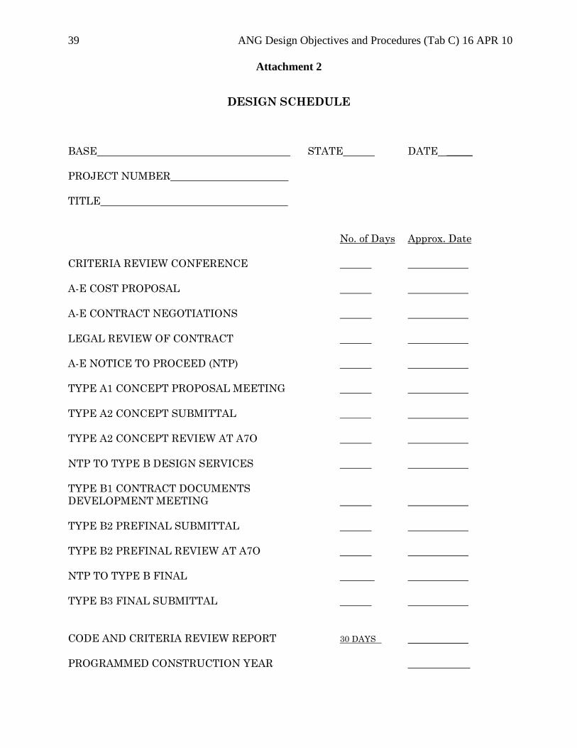
39 ANG Design Objectives and Procedures (Tab C) 16 APR 10
Attachment 2
DESIGN SCHEDULE
BASE STATE DATE _____
PROJECT NUMBER
TITLE
No. of Days Approx. Date
CRITERIA REVIEW CONFERENCE
A-E COST PROPOSAL
A-E CONTRACT NEGOTIATIONS
LEGAL REVIEW OF CONTRACT
A-E NOTICE TO PROCEED (NTP)
TYPE A1 CONCEPT PROPOSAL MEETING
TYPE A2 CONCEPT SUBMITTAL
TYPE A2 CONCEPT REVIEW AT A7O
NTP TO TYPE B DESIGN SERVICES
TYPE B1 CONTRACT DOCUMENTS
DEVELOPMENT MEETING
TYPE B2 PREFINAL SUBMITTAL
TYPE B2 PREFINAL REVIEW AT A7O
NTP TO TYPE B FINAL
TYPE B3 FINAL SUBMITTAL
CODE AND CRITERIA REVIEW REPORT 30 DAYS
PROGRAMMED CONSTRUCTION YEAR ___________
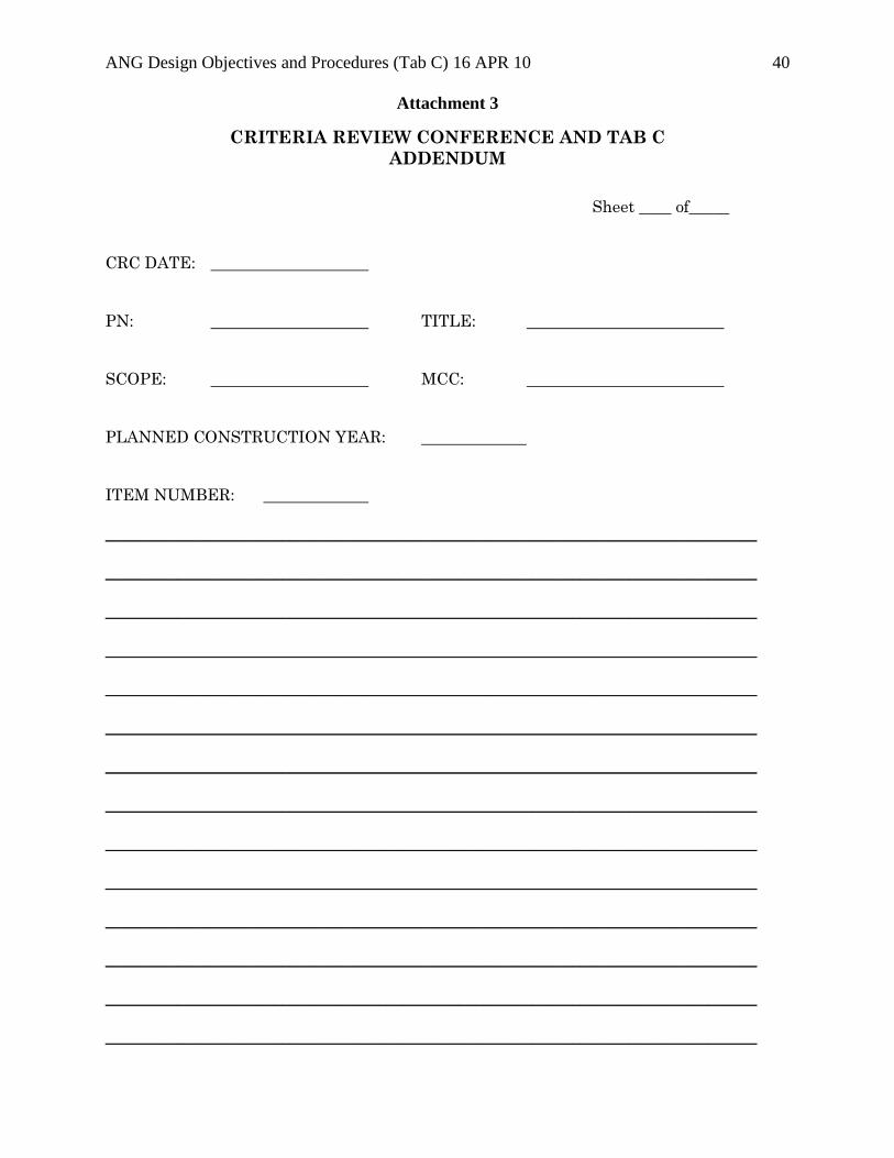
ANG Design Objectives and Procedures (Tab C) 16 APR 10 40
Attachment 3
CRITERIA REVIEW CONFERENCE AND TAB C
ADDENDUM
Sheet ____ of_____
CRC DATE:
PN: TITLE:
SCOPE: MCC:
PLANNED CONSTRUCTION YEAR:
ITEM NUMBER:
_________________________________________________________________________________
_________________________________________________________________________________
_________________________________________________________________________________
_________________________________________________________________________________
_________________________________________________________________________________
_________________________________________________________________________________
_________________________________________________________________________________
_________________________________________________________________________________
_________________________________________________________________________________
_________________________________________________________________________________
_________________________________________________________________________________
_________________________________________________________________________________
_________________________________________________________________________________
_________________________________________________________________________________
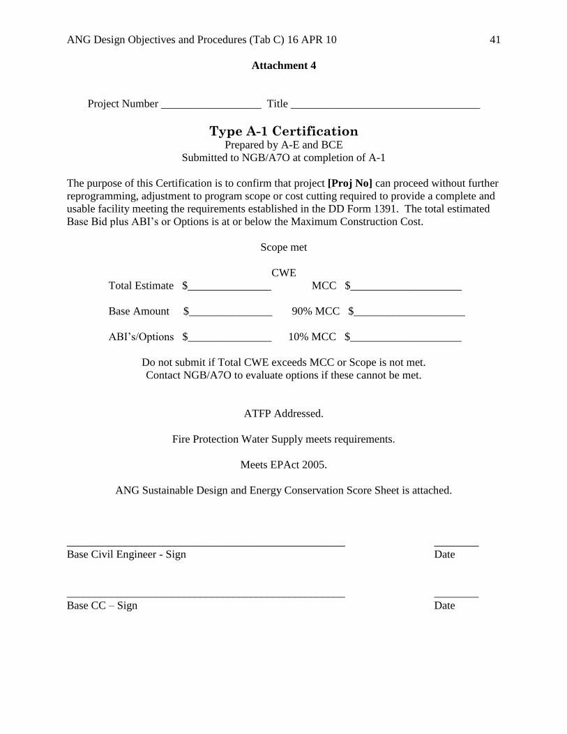
ANG Design Objectives and Procedures (Tab C) 16 APR 10 41
Attachment 4
Project Number __________________ Title __________________________________
Type A-1 Certification Prepared by A-E and BCE
Submitted to NGB/A7O at completion of A-1
The purpose of this Certification is to confirm that project [Proj No] can proceed without further
reprogramming, adjustment to program scope or cost cutting required to provide a complete and
usable facility meeting the requirements established in the DD Form 1391. The total estimated
Base Bid plus ABI’s or Options is at or below the Maximum Construction Cost.
Scope met
CWE
Total Estimate $_______________ MCC $____________________
Base Amount $_______________ 90% MCC $____________________
ABI’s/Options $_______________ 10% MCC $____________________
Do not submit if Total CWE exceeds MCC or Scope is not met.
Contact NGB/A7O to evaluate options if these cannot be met.
ATFP Addressed.
Fire Protection Water Supply meets requirements.
Meets EPAct 2005.
ANG Sustainable Design and Energy Conservation Score Sheet is attached.
__________________________________________________ ________
Base Civil Engineer - Sign Date
__________________________________________________ ________
Base CC – Sign Date
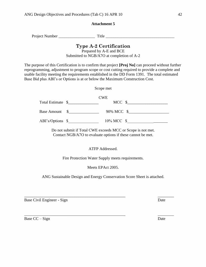
ANG Design Objectives and Procedures (Tab C) 16 APR 10 42
Attachment 5
Project Number __________________ Title __________________________________
Type A-2 Certification Prepared by A-E and BCE
Submitted to NGB/A7O at completion of A-2
The purpose of this Certification is to confirm that project [Proj No] can proceed without further
reprogramming, adjustment to program scope or cost cutting required to provide a complete and
usable facility meeting the requirements established in the DD Form 1391. The total estimated
Base Bid plus ABI’s or Options is at or below the Maximum Construction Cost.
Scope met
CWE
Total Estimate $_______________ MCC $____________________
Base Amount $_______________ 90% MCC $____________________
ABI’s/Options $_______________ 10% MCC $____________________
Do not submit if Total CWE exceeds MCC or Scope is not met.
Contact NGB/A7O to evaluate options if these cannot be met.
ATFP Addressed.
Fire Protection Water Supply meets requirements.
Meets EPAct 2005.
ANG Sustainable Design and Energy Conservation Score Sheet is attached.
__________________________________________________ ________
Base Civil Engineer - Sign Date
__________________________________________________ ________
Base CC – Sign Date
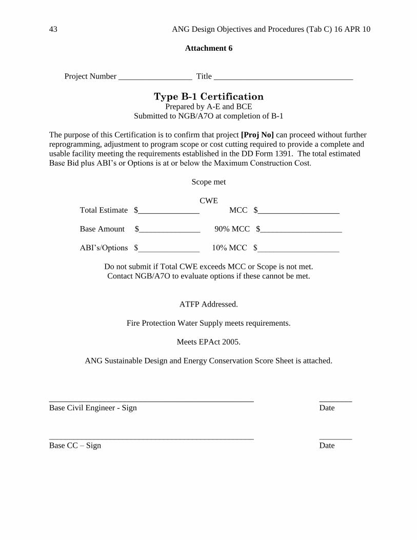
43 ANG Design Objectives and Procedures (Tab C) 16 APR 10
Attachment 6
Project Number __________________ Title __________________________________
Type B-1 Certification Prepared by A-E and BCE
Submitted to NGB/A7O at completion of B-1
The purpose of this Certification is to confirm that project [Proj No] can proceed without further
reprogramming, adjustment to program scope or cost cutting required to provide a complete and
usable facility meeting the requirements established in the DD Form 1391. The total estimated
Base Bid plus ABI’s or Options is at or below the Maximum Construction Cost.
Scope met
CWE
Total Estimate $_______________ MCC $____________________
Base Amount $_______________ 90% MCC $____________________
ABI’s/Options $_______________ 10% MCC $____________________
Do not submit if Total CWE exceeds MCC or Scope is not met.
Contact NGB/A7O to evaluate options if these cannot be met.
ATFP Addressed.
Fire Protection Water Supply meets requirements.
Meets EPAct 2005.
ANG Sustainable Design and Energy Conservation Score Sheet is attached.
__________________________________________________ ________
Base Civil Engineer - Sign Date
__________________________________________________ ________
Base CC – Sign Date

ANG Design Objectives and Procedures (Tab C) 16 APR 10 44
Attachment 7
Project Number __________________ Title __________________________________
Type B-2 Certification Prepared by A-E and BCE
Submitted to NGB/A7O at completion of B-2
The purpose of this Certification is to confirm that project [Proj No] can proceed without further
reprogramming, adjustment to program scope or cost cutting required to provide a complete and
usable facility meeting the requirements established in the DD Form 1391. The total estimated
Base Bid plus ABI’s or Options is at or below the Maximum Construction Cost.
Scope met
CWE
Total Estimate $_______________ MCC $____________________
Base Amount $_______________ 90% MCC $____________________
ABI’s/Options $_______________ 10% MCC $____________________
Do not submit if Total CWE exceeds MCC or Scope is not met.
Contact NGB/A7O to evaluate options if these cannot be met.
ATFP Addressed.
Fire Protection Water Supply meets requirements.
Meets EPAct 2005.
ANG Sustainable Design and Energy Conservation Score Sheet is attached.
__________________________________________________ ________
Base Civil Engineer - Sign Date
__________________________________________________ ________
Base CC – Sign Date
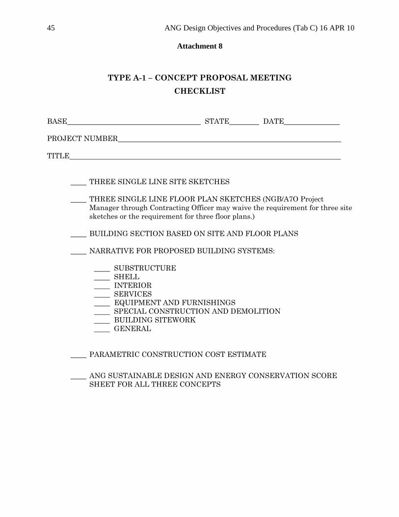
45 ANG Design Objectives and Procedures (Tab C) 16 APR 10
Attachment 8
TYPE A-1 – CONCEPT PROPOSAL MEETING
CHECKLIST
BASE STATE DATE
PROJECT NUMBER
TITLE
THREE SINGLE LINE SITE SKETCHES
THREE SINGLE LINE FLOOR PLAN SKETCHES (NGB/A7O Project
Manager through Contracting Officer may waive the requirement for three site
sketches or the requirement for three floor plans.)
BUILDING SECTION BASED ON SITE AND FLOOR PLANS
NARRATIVE FOR PROPOSED BUILDING SYSTEMS:
SUBSTRUCTURE
SHELL
INTERIOR
SERVICES
EQUIPMENT AND FURNISHINGS
SPECIAL CONSTRUCTION AND DEMOLITION
BUILDING SITEWORK
GENERAL
PARAMETRIC CONSTRUCTION COST ESTIMATE
ANG SUSTAINABLE DESIGN AND ENERGY CONSERVATION SCORE
SHEET FOR ALL THREE CONCEPTS
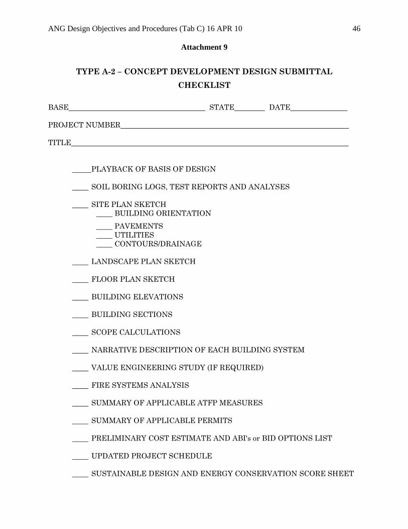
ANG Design Objectives and Procedures (Tab C) 16 APR 10 46
Attachment 9
TYPE A-2 – CONCEPT DEVELOPMENT DESIGN SUBMITTAL
CHECKLIST
BASE STATE DATE
PROJECT NUMBER
TITLE
PLAYBACK OF BASIS OF DESIGN
SOIL BORING LOGS, TEST REPORTS AND ANALYSES
SITE PLAN SKETCH
BUILDING ORIENTATION
PAVEMENTS
UTILITIES
CONTOURS/DRAINAGE
LANDSCAPE PLAN SKETCH
FLOOR PLAN SKETCH
BUILDING ELEVATIONS
BUILDING SECTIONS
SCOPE CALCULATIONS
NARRATIVE DESCRIPTION OF EACH BUILDING SYSTEM
VALUE ENGINEERING STUDY (IF REQUIRED)
FIRE SYSTEMS ANALYSIS
SUMMARY OF APPLICABLE ATFP MEASURES
SUMMARY OF APPLICABLE PERMITS
PRELIMINARY COST ESTIMATE AND ABI's or BID OPTIONS LIST
UPDATED PROJECT SCHEDULE
SUSTAINABLE DESIGN AND ENERGY CONSERVATION SCORE SHEET
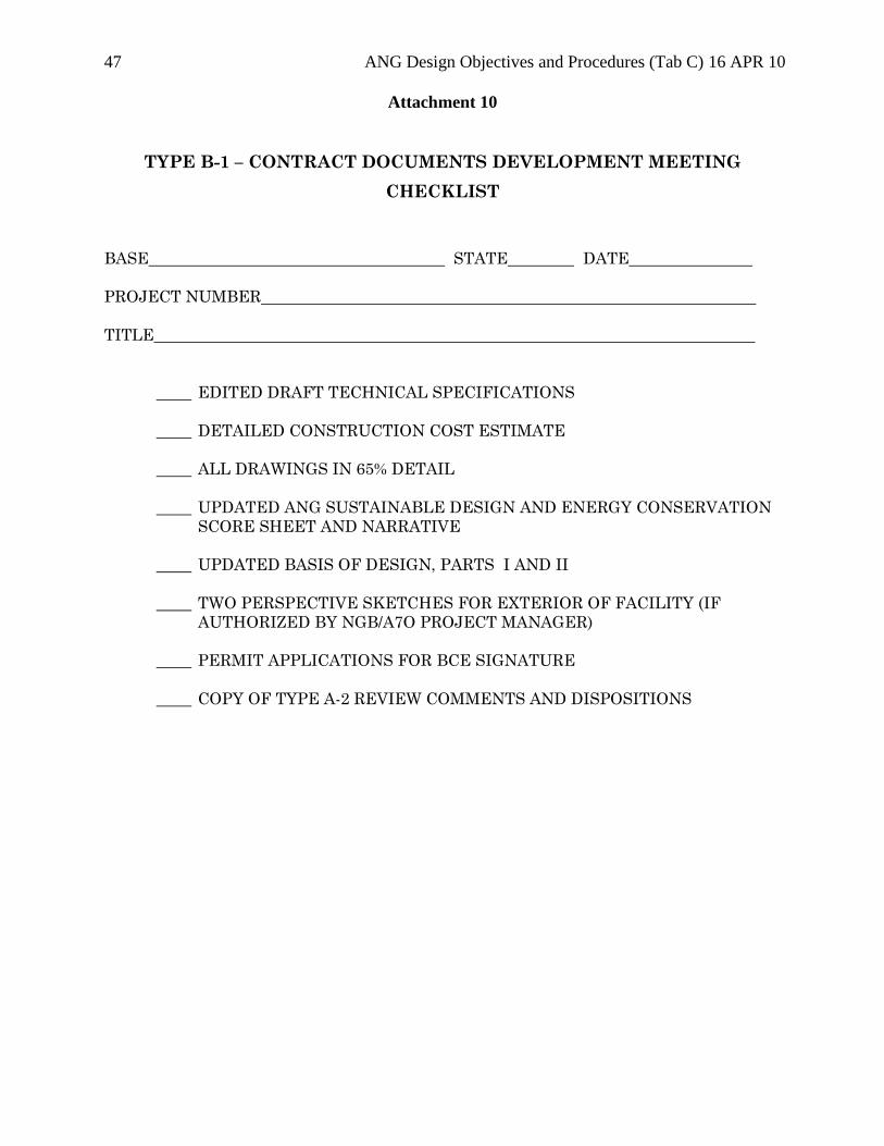
47 ANG Design Objectives and Procedures (Tab C) 16 APR 10
Attachment 10
TYPE B-1 – CONTRACT DOCUMENTS DEVELOPMENT MEETING
CHECKLIST
BASE STATE DATE
PROJECT NUMBER
TITLE
EDITED DRAFT TECHNICAL SPECIFICATIONS
DETAILED CONSTRUCTION COST ESTIMATE
ALL DRAWINGS IN 65% DETAIL
UPDATED ANG SUSTAINABLE DESIGN AND ENERGY CONSERVATION
SCORE SHEET AND NARRATIVE
UPDATED BASIS OF DESIGN, PARTS I AND II
TWO PERSPECTIVE SKETCHES FOR EXTERIOR OF FACILITY (IF
AUTHORIZED BY NGB/A7O PROJECT MANAGER)
PERMIT APPLICATIONS FOR BCE SIGNATURE
COPY OF TYPE A-2 REVIEW COMMENTS AND DISPOSITIONS
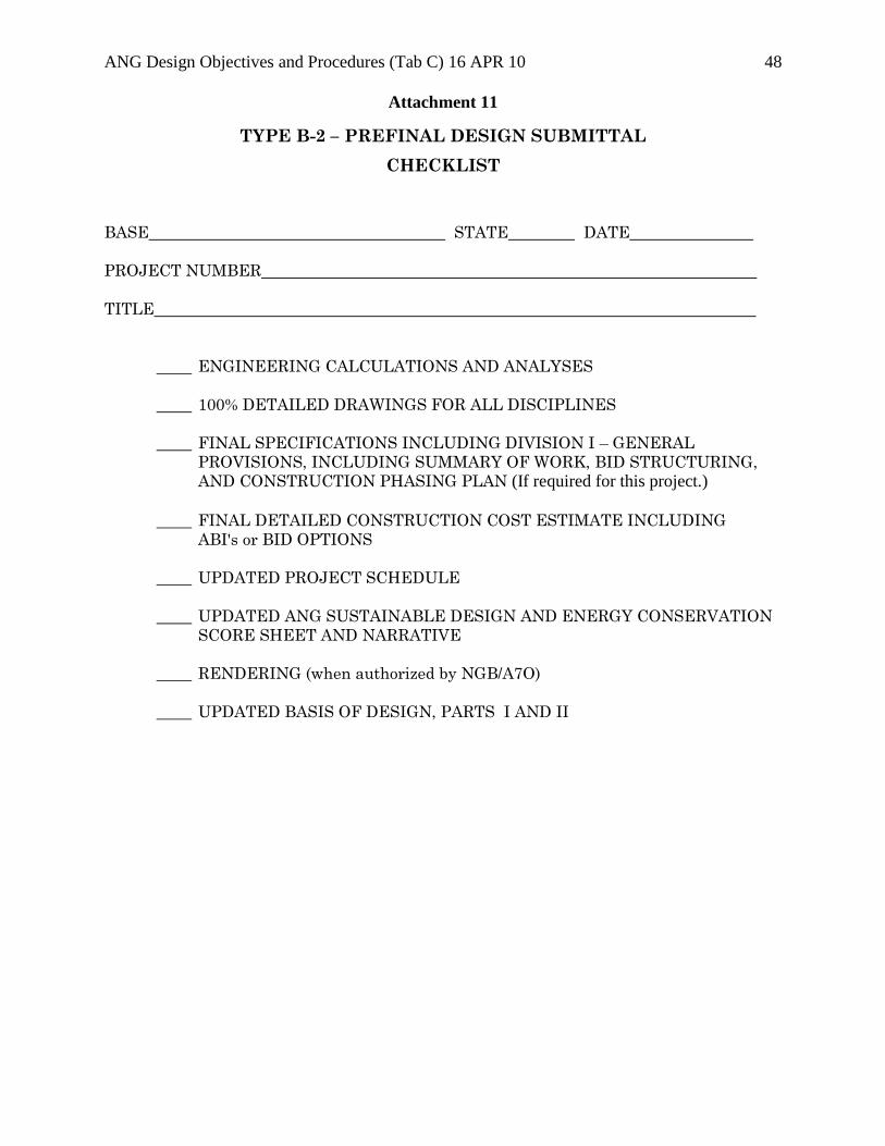
ANG Design Objectives and Procedures (Tab C) 16 APR 10 48
Attachment 11
TYPE B-2 – PREFINAL DESIGN SUBMITTAL
CHECKLIST
BASE STATE DATE
PROJECT NUMBER
TITLE
ENGINEERING CALCULATIONS AND ANALYSES
100% DETAILED DRAWINGS FOR ALL DISCIPLINES
FINAL SPECIFICATIONS INCLUDING DIVISION I – GENERAL
PROVISIONS, INCLUDING SUMMARY OF WORK, BID STRUCTURING,
AND CONSTRUCTION PHASING PLAN (If required for this project.)
FINAL DETAILED CONSTRUCTION COST ESTIMATE INCLUDING
ABI's or BID OPTIONS
UPDATED PROJECT SCHEDULE
UPDATED ANG SUSTAINABLE DESIGN AND ENERGY CONSERVATION
SCORE SHEET AND NARRATIVE
RENDERING (when authorized by NGB/A7O)
UPDATED BASIS OF DESIGN, PARTS I AND II
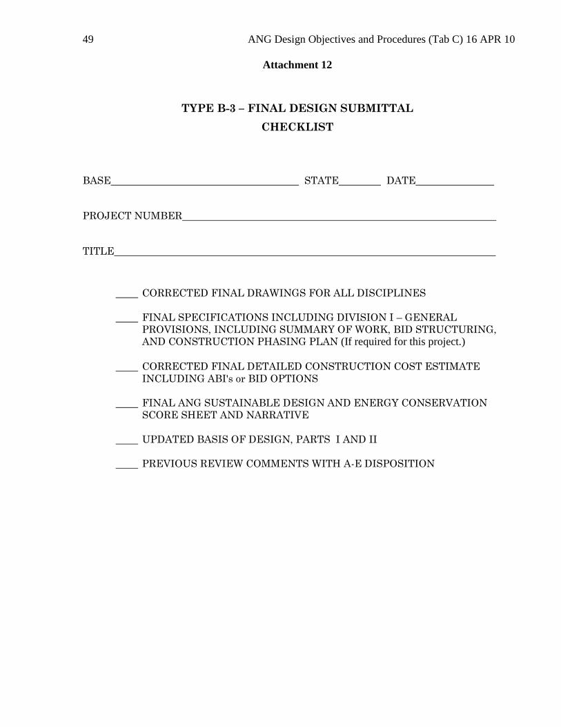
49 ANG Design Objectives and Procedures (Tab C) 16 APR 10
Attachment 12
TYPE B-3 – FINAL DESIGN SUBMITTAL
CHECKLIST
BASE STATE DATE
PROJECT NUMBER
TITLE
CORRECTED FINAL DRAWINGS FOR ALL DISCIPLINES
FINAL SPECIFICATIONS INCLUDING DIVISION I – GENERAL
PROVISIONS, INCLUDING SUMMARY OF WORK, BID STRUCTURING,
AND CONSTRUCTION PHASING PLAN (If required for this project.)
CORRECTED FINAL DETAILED CONSTRUCTION COST ESTIMATE
INCLUDING ABI's or BID OPTIONS
FINAL ANG SUSTAINABLE DESIGN AND ENERGY CONSERVATION
SCORE SHEET AND NARRATIVE
UPDATED BASIS OF DESIGN, PARTS I AND II
PREVIOUS REVIEW COMMENTS WITH A-E DISPOSITION
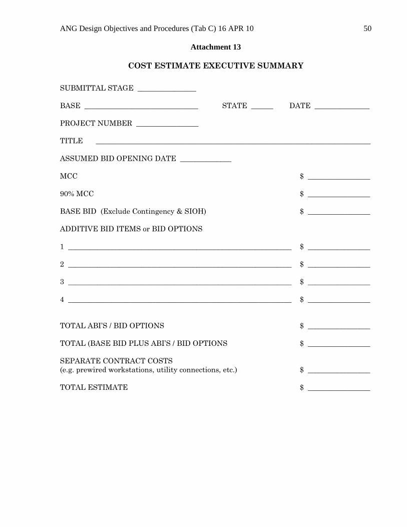
ANG Design Objectives and Procedures (Tab C) 16 APR 10 50
Attachment 13
COST ESTIMATE EXECUTIVE SUMMARY
SUBMITTAL STAGE ________________
BASE _______________________________ STATE ______ DATE _______________
PROJECT NUMBER _________________
TITLE ___________________________________________________________________________
ASSUMED BID OPENING DATE ______________
MCC $ _________________
90% MCC $ _________________
BASE BID (Exclude Contingency & SIOH) $ _________________
ADDITIVE BID ITEMS or BID OPTIONS
1 _____________________________________________________________ $ _________________
2 _____________________________________________________________ $ _________________
3 _____________________________________________________________ $ _________________
4 _____________________________________________________________ $ _________________
TOTAL ABI’S / BID OPTIONS $ _________________
TOTAL (BASE BID PLUS ABI’S / BID OPTIONS $ _________________
SEPARATE CONTRACT COSTS
(e.g. prewired workstations, utility connections, etc.) $ _________________
TOTAL ESTIMATE $ _________________
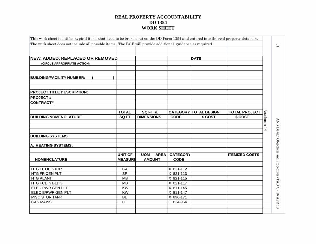
REAL PROPERTY ACCOUNTABILITY
DD 1354
WORK SHEET
This work sheet identifies typical items that need to be broken out on the DD Form 1354 and entered into the real property database.
The work sheet does not include all possible items. The BCE will provide additional guidance as required.
NEW, ADDED, REPLACED OR REMOVED DATE:
(CIRCLE APPROPRIATE ACTION)
BUILDING/FACILITY NUMBER: ( )
PROJECT TITLE DESCRIPTION:
PROJECT #
CONTRACT#
TOTAL SQ FT & CATEGORY TOTAL DESIGN TOTAL PROJECT
BUILDING NOMENCLATURE SQ FT DIMENSIONS CODE $ COST $ COST
BUILDING SYSTEMS
A. HEATING SYSTEMS:
UNIT OF UOM AREA CATEGORY ITEMIZED COSTS
NOMENCLATURE MEASURE AMOUNT CODE
HTG FL OIL STOR GA X 821-112
HTG FR CEN PLT SF X 821-113
HTG PLANT MB X 821-115
HTG FCLTY BLDG MB X 821-117
ELEC PWR GEN PLT KW X 811-145
ELEC E/PWR GEN PLT KW X 811-147
MISC STOR TANK BL X 890-171
GAS MAINS LF E 824-964
Attach
men
t 14
51 A
NG
Desig
n O
bjectiv
es and P
roced
ures (T
AB
C) 1
6 A
PR
10
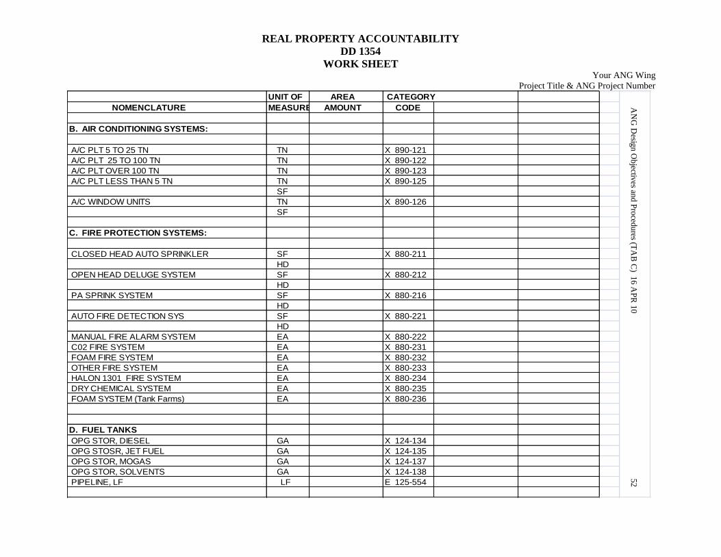
REAL PROPERTY ACCOUNTABILITY
DD 1354
WORK SHEET Your ANG Wing
Project Title & ANG Project Number
UNIT OF AREA CATEGORY
NOMENCLATURE MEASURE AMOUNT CODE
B. AIR CONDITIONING SYSTEMS:
A/C PLT 5 TO 25 TN TN X 890-121
A/C PLT 25 TO 100 TN TN X 890-122
A/C PLT OVER 100 TN TN X 890-123
A/C PLT LESS THAN 5 TN TN X 890-125
SF
A/C WINDOW UNITS TN X 890-126
SF
C. FIRE PROTECTION SYSTEMS:
CLOSED HEAD AUTO SPRINKLER SF X 880-211
HD
OPEN HEAD DELUGE SYSTEM SF X 880-212
HD
PA SPRINK SYSTEM SF X 880-216
HD
AUTO FIRE DETECTION SYS SF X 880-221
HD
MANUAL FIRE ALARM SYSTEM EA X 880-222
C02 FIRE SYSTEM EA X 880-231
FOAM FIRE SYSTEM EA X 880-232
OTHER FIRE SYSTEM EA X 880-233
HALON 1301 FIRE SYSTEM EA X 880-234
DRY CHEMICAL SYSTEM EA X 880-235
FOAM SYSTEM (Tank Farms) EA X 880-236
D. FUEL TANKS
OPG STOR, DIESEL GA X 124-134
OPG STOSR, JET FUEL GA X 124-135
OPG STOR, MOGAS GA X 124-137
OPG STOR, SOLVENTS GA X 124-138
PIPELINE, LF LF E 125-554
AN
G D
esign
Ob
jectives an
d P
roced
ures (T
AB
C) 1
6 A
PR
10
52
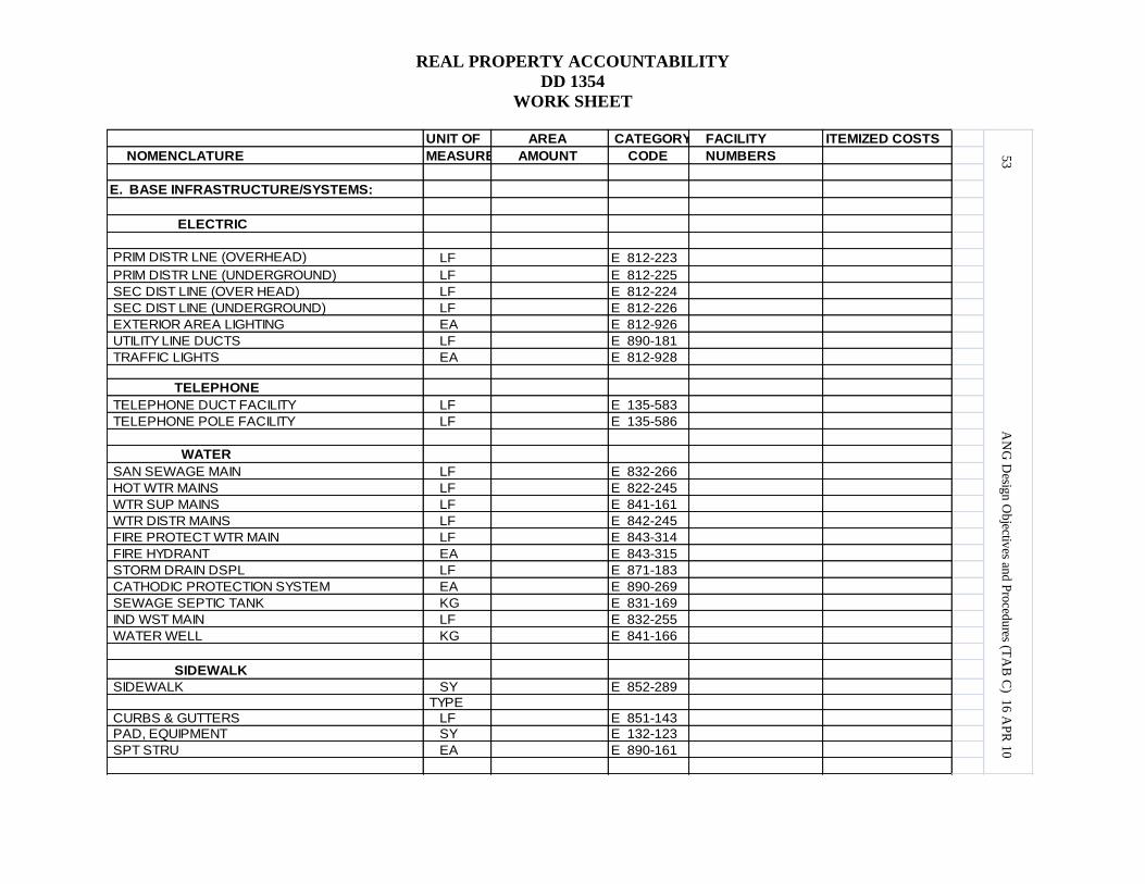
REAL PROPERTY ACCOUNTABILITY
DD 1354
WORK SHEET
UNIT OF AREA CATEGORY FACILITY ITEMIZED COSTS
NOMENCLATURE MEASURE AMOUNT CODE NUMBERS
E. BASE INFRASTRUCTURE/SYSTEMS:
ELECTRIC
PRIM DISTR LNE (OVERHEAD) LF E 812-223
PRIM DISTR LNE (UNDERGROUND) LF E 812-225
SEC DIST LINE (OVER HEAD) LF E 812-224
SEC DIST LINE (UNDERGROUND) LF E 812-226
EXTERIOR AREA LIGHTING EA E 812-926
UTILITY LINE DUCTS LF E 890-181
TRAFFIC LIGHTS EA E 812-928
TELEPHONE
TELEPHONE DUCT FACILITY LF E 135-583
TELEPHONE POLE FACILITY LF E 135-586
WATER
SAN SEWAGE MAIN LF E 832-266
HOT WTR MAINS LF E 822-245
WTR SUP MAINS LF E 841-161
WTR DISTR MAINS LF E 842-245
FIRE PROTECT WTR MAIN LF E 843-314
FIRE HYDRANT EA E 843-315
STORM DRAIN DSPL LF E 871-183
CATHODIC PROTECTION SYSTEM EA E 890-269
SEWAGE SEPTIC TANK KG E 831-169
IND WST MAIN LF E 832-255
WATER WELL KG E 841-166
SIDEWALK
SIDEWALK SY E 852-289
TYPE
CURBS & GUTTERS LF E 851-143
PAD, EQUIPMENT SY E 132-123
SPT STRU EA E 890-161
53 A
NG
Desig
n O
bjectiv
es and P
roced
ures (T
AB
C) 1
6 A
PR
10
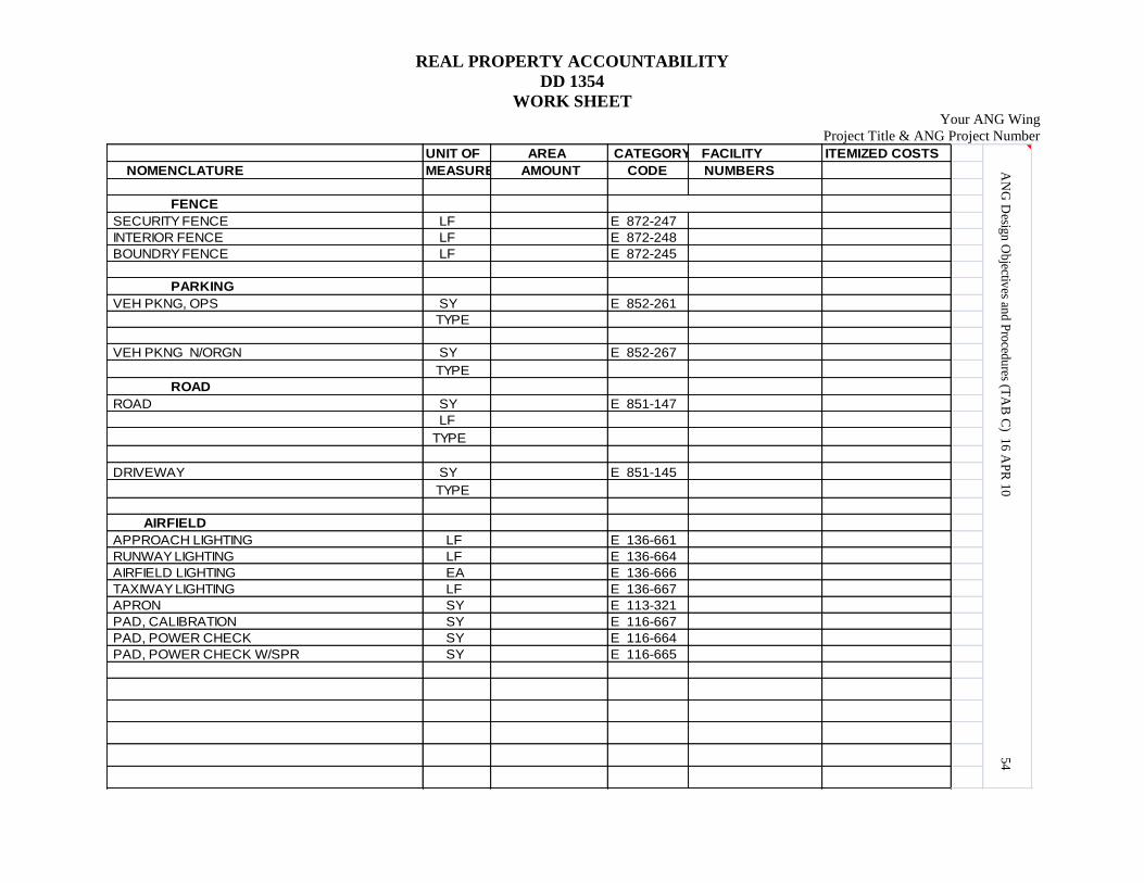
REAL PROPERTY ACCOUNTABILITY
DD 1354
WORK SHEET Your ANG Wing
Project Title & ANG Project Number
UNIT OF AREA CATEGORY FACILITY ITEMIZED COSTS
NOMENCLATURE MEASURE AMOUNT CODE NUMBERS
FENCE
SECURITY FENCE LF E 872-247
INTERIOR FENCE LF E 872-248
BOUNDRY FENCE LF E 872-245
PARKING
VEH PKNG, OPS SY E 852-261
TYPE
VEH PKNG N/ORGN SY E 852-267
TYPE
ROAD
ROAD SY E 851-147
LF
TYPE
DRIVEWAY SY E 851-145
TYPE
AIRFIELD
APPROACH LIGHTING LF E 136-661
RUNWAY LIGHTING LF E 136-664
AIRFIELD LIGHTING EA E 136-666
TAXIWAY LIGHTING LF E 136-667
APRON SY E 113-321
PAD, CALIBRATION SY E 116-667
PAD, POWER CHECK SY E 116-664
PAD, POWER CHECK W/SPR SY E 116-665
AN
G D
esign
Ob
jectives an
d P
roced
ures (T
AB
C) 1
6 A
PR
10
54
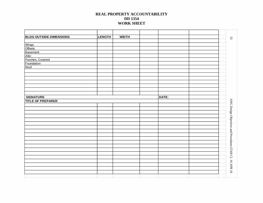
REAL PROPERTY ACCOUNTABILITY
DD 1354
WORK SHEET
BLDG OUTSIDE DIMENSIONS LENGTH WIDTH
Wings
Offsets
Basement
Attic
Porches, Covered
Foundation
Roof
SIGNATURE DATE:
TITLE OF PREPARER
55 A
NG
Desig
n O
bjectiv
es and P
roced
ures (T
AB
C) 1
6 A
PR
10
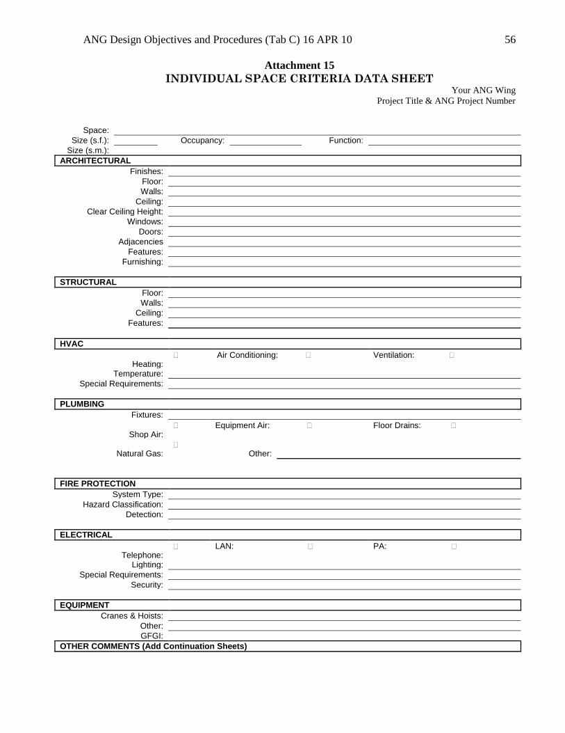
ANG Design Objectives and Procedures (Tab C) 16 APR 10 56
Attachment 15
INDIVIDUAL SPACE CRITERIA DATA SHEET Your ANG Wing
Project Title & ANG Project Number
Space:
Size (s.f.): Occupancy: Function:
Size (s.m.):
ARCHITECTURAL
Finishes:
Floor:
Walls:
Ceiling:
Clear Ceiling Height:
Windows:
Doors:
Adjacencies
Features:
Furnishing:
STRUCTURAL
Floor:
Walls:
Ceiling:
Features:
HVAC
Heating:
Air Conditioning: Ventilation:
Temperature:
Special Requirements:
PLUMBING
Fixtures:
Shop Air:
Equipment Air: Floor Drains:
Natural Gas:
Other:
FIRE PROTECTION
System Type:
Hazard Classification:
Detection:
ELECTRICAL
Telephone:
LAN: PA:
Lighting:
Special Requirements:
Security:
EQUIPMENT
Cranes & Hoists:
Other:
GFGI:
OTHER COMMENTS (Add Continuation Sheets)
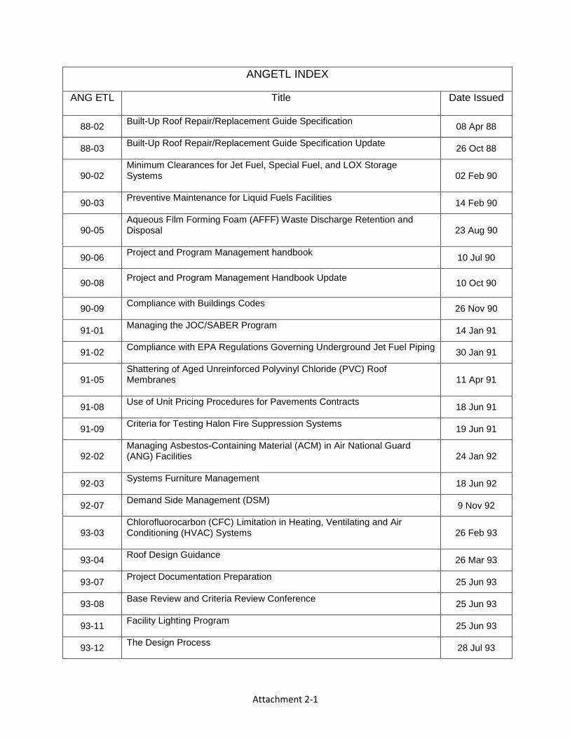
Attachment 2-1
ANGETL INDEX
ANG ETL
Title Date Issued
88-02 Built-Up Roof Repair/Replacement Guide Specification
08 Apr 88
88-03 Built-Up Roof Repair/Replacement Guide Specification Update
26 Oct 88
90-02 Minimum Clearances for Jet Fuel, Special Fuel, and LOX Storage Systems
02 Feb 90
90-03 Preventive Maintenance for Liquid Fuels Facilities
14 Feb 90
90-05 Aqueous Film Forming Foam (AFFF) Waste Discharge Retention and Disposal
23 Aug 90
90-06 Project and Program Management handbook
10 Jul 90
90-08 Project and Program Management Handbook Update
10 Oct 90
90-09 Compliance with Buildings Codes
26 Nov 90
91-01 Managing the JOC/SABER Program
14 Jan 91
91-02 Compliance with EPA Regulations Governing Underground Jet Fuel Piping
30 Jan 91
91-05 Shattering of Aged Unreinforced Polyvinyl Chloride (PVC) Roof Membranes
11 Apr 91
91-08 Use of Unit Pricing Procedures for Pavements Contracts
18 Jun 91
91-09 Criteria for Testing Halon Fire Suppression Systems
19 Jun 91
92-02 Managing Asbestos-Containing Material (ACM) in Air National Guard (ANG) Facilities
24 Jan 92
92-03 Systems Furniture Management
18 Jun 92
92-07 Demand Side Management (DSM)
9 Nov 92
93-03 Chlorofluorocarbon (CFC) Limitation in Heating, Ventilating and Air Conditioning (HVAC) Systems
26 Feb 93
93-04 Roof Design Guidance
26 Mar 93
93-07 Project Documentation Preparation
25 Jun 93
93-08 Base Review and Criteria Review Conference
25 Jun 93
93-11 Facility Lighting Program
25 Jun 93
93-12 The Design Process
28 Jul 93
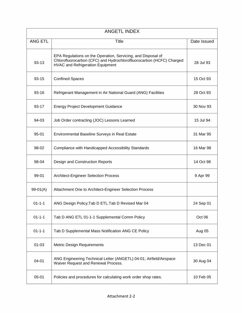
Attachment 2-2
ANGETL INDEX
ANG ETL
Title Date Issued
93-13
EPA Regulations on the Operation, Servicing, and Disposal of Chlorofluorocarbon (CFC) and Hydrochloroflluorocarbon (HCFC) Charged HVAC and Refrigeration Equipment
28 Jul 93
93-15 Confined Spaces
15 Oct 93
93-16 Refrigerant Management in Air National Guard (ANG) Facilities
28 Oct 93
93-17 Energy Project Development Guidance
30 Nov 93
94-03 Job Order contracting (JOC) Lessons Learned
15 Jul 94
95-01 Environmental Baseline Surveys in Real Estate
31 Mar 95
98-02 Compliance with Handicapped Accessibility Standards
16 Mar 98
98-04 Design and Construction Reports
14 Oct 98
99-01 Architect-Engineer Selection Process
9 Apr 99
99-01(A) Attachment One to Architect-Engineer Selection Process
01-1-1 ANG Design Policy;Tab D ETL.Tab D Revised Mar 04
24 Sep 01
01-1-1 Tab D ANG ETL 01-1-1 Supplemental Comm Policy
Oct 06
01-1-1 Tab D Supplemental Mass Notification ANG CE Policy
Aug 05
01-03 Metric Design Requirements
13 Dec 01
04-01
ANG Engineering Technical Letter (ANGETL) 04-01; Airfield/Airspace Waiver Request and Renewal Process.
30 Aug 04
05-01 Policies and procedures for calculating work order shop rates.
10 Feb 05
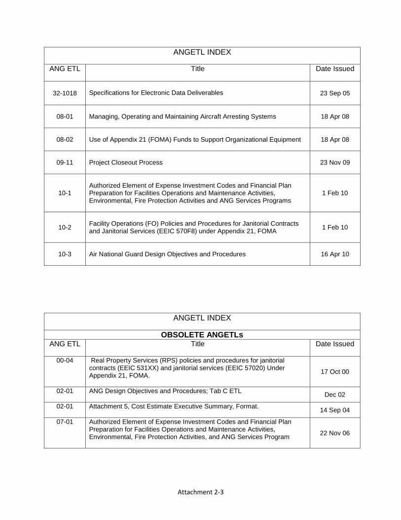
Attachment 2-3
ANGETL INDEX
ANG ETL
Title Date Issued
32-1018
Specifications for Electronic Data Deliverables
23 Sep 05
08-01 Managing, Operating and Maintaining Aircraft Arresting Systems
18 Apr 08
08-02 Use of Appendix 21 (FOMA) Funds to Support Organizational Equipment
18 Apr 08
09-11 Project Closeout Process
23 Nov 09
10-1
Authorized Element of Expense Investment Codes and Financial Plan Preparation for Facilities Operations and Maintenance Activities, Environmental, Fire Protection Activities and ANG Services Programs
1 Feb 10
10-2
Facility Operations (FO) Policies and Procedures for Janitorial Contracts and Janitorial Services (EEIC 570F8) under Appendix 21, FOMA
1 Feb 10
10-3 Air National Guard Design Objectives and Procedures
16 Apr 10
ANGETL INDEX
OBSOLETE ANGETLs ANG ETL
Title Date Issued
00-04 Real Property Services (RPS) policies and procedures for janitorial contracts (EEIC 531XX) and janitorial services (EEIC 57020) Under Appendix 21, FOMA.
17 Oct 00
02-01 ANG Design Objectives and Procedures; Tab C ETL
Dec 02
02-01 Attachment 5, Cost Estimate Executive Summary, Format.
14 Sep 04
07-01 Authorized Element of Expense Investment Codes and Financial Plan Preparation for Facilities Operations and Maintenance Activities, Environmental, Fire Protection Activities, and ANG Services Program
22 Nov 06