Embed Size (px)
Citation preview

DDEC IV ON-HIGHWAY - EGR APPLICATION AND INSTALLATION
6 COMMUNICATION PROTOCOLS
Section Page
6.1 OVERVIEW ............................................................................................. 6-3
6.2 SAE J1587 .............................................................................................. 6-5
6.3 SAE J1922 .............................................................................................. 6-37
6.4 SAE J1939 .............................................................................................. 6-45
All information subject to change without notice. (Rev. 3/05) 6-17SA743 0503 Copyright © 2005 DETROIT DIESEL CORPORATION

COMMUNICATION PROTOCOLS
THIS PAGE INTENTIONALLY LEFT BLANK
6-2 All information subject to change without notice. (Rev. 3/05)7SA743 0503 Copyright © 2005 DETROIT DIESEL CORPORATION

DDEC IV ON-HIGHWAY - EGR APPLICATION AND INSTALLATION
6.1 OVERVIEW
Key components of the DDEC IV system are the serial communication links SAE J1587, SAEJ1922, and SAE J1939. Using these communication links allows DDEC IV to offer the followingfunctionality:
Transmitting sensor information from the ECM via the data link at regular intervals and/orupon request to obtain data and to monitor for failures
Sharing information between stand-alone modules used in the system via the data link
Sharing engine data with electronic dashboard displays and vehicle managementinformation systems via the data link
Transmitting and performing diagnostic procedures from external instrumentation such asthe hand-held diagnostic data readers or DDDL via the data link
Transmitting customer requested changes to the ECM from external instrumentation viathe data link
Transmitting to the powertrain the messages assigned to both the engine and thetransmission retarder.
The following industry standard Society of Automotive Engineers (SAE) documents can beused as a reference:
SAE J1587, Electronic Data Interchange Between Microcomputer Systems In HeavyDuty Vehicle Applications
SAE J1708, Serial Data Communications Between Microcomputer Systems In HeavyDuty Vehicle Applications
SAE J1922, Powertrain Control Interface For Electronic Controls Used In Medium AndHeavy Duty Diesel On-highway Vehicle Applications
SAE J1939/71, Vehicle Application Layer
SAE J1939, Top Layer (Overview)
SAE J1939/01, Truck and Bus Applications
SAE J1939/11, Physical Layer
SAE J1939/21, Data Link Layer
SAE J1939/73, Application Layer Diagnostics
To obtain a copy of the above documents contact the Society of Automotive Engineers (SAE).
SAE International400 Commonwealth DriveWarrendale, PA 15096Attention: PublicationsPhone: (412) 776-4970www.sae.org
All information subject to change without notice. (Rev. 3/05) 6-37SA743 0503 Copyright © 2005 DETROIT DIESEL CORPORATION

COMMUNICATION PROTOCOLS
THIS PAGE INTENTIONALLY LEFT BLANK
6-4 All information subject to change without notice. (Rev. 3/05)7SA743 0503 Copyright © 2005 DETROIT DIESEL CORPORATION

DDEC IV ON-HIGHWAY - EGR APPLICATION AND INSTALLATION
6.2 SAE J1587
SAE RP J1587 defines the recommended format of messages and data being communicatedbetween microprocessors used in heavy-duty vehicle applications. Circuits 900 (Data Link +)and 901 (Data Link -) as shown on the Vehicle Interface Harness schematic are used as theJ1587 communication link. These circuits also exist in the DDEC six-pin diagnostic connectorfor use with the DDR.
NOTE:The maximum length for the SAE J1587 Data Link is 40 m (130 ft).
6.2.1 MESSAGE FORMAT
A complete description of the DDEC IV parameters is provided within this section of the manual.DDEC IV transmits parametric data at SAE J1587 recommended rates in packed message form.The first byte or character of each message is the Message Identification character (MID). TheMID identifies which microcomputer on the serial communication link originated the information.Each device in the system originating messages must have a unique MID. The assignment ofMIDs should be based on those listed in SAE RP J1587. The primary MID for DDEC IV is 128.Engines with 12 and 16 cylinders use MID 128 and MID 175. Engines with 20 cylinders useMID 128, MID 175 and MID 183.
The ProDriver display uses MID 171. Off-board diagnostic tools like hand-held readers shouldbe identified by MID 172. Off-board programming stations like Vehicle Engine ProgrammingStation (VEPS) should be identified by MID 182. Messages using MIDs as recommended bySAE RP J1587 will be responded to by the ECM.
Subsystems also require identifiers. The subsystem identifier character (SID) is a single bytecharacter used to identify field-repairable or replaceable subsystems for which failures can bedetected or isolated. SIDs are used in conjunction with SAE standard diagnostic codes defined inJ1587 within PID194.
The identifiers used by DDEC are defined and listed in Table 6-1.
Identifier Description
Failure Mode Identifier (FMI)The FMI describes the type of failure detected in thesubsystem and identified by the PID or SID.
Message Identification Character (MID)
The MID is the first byte or character of eachmessage that identifies which microcomputer onDDEC 1587 serial communication link originatedthe information.
Parameter Identification Character (PID)A PID is a single byte character used in DDEC 1587messages to identify the data byte(s) that follow.PIDs identify the parameters transmitted.
Subsystem Identification Character (SID)A SID is a single byte character used to identifyfield-repairable or replaceable subsystems for whichfailures can be detected or isolated.
Table 6-1 Identifiers Used by DDEC
All information subject to change without notice. (Rev. 3/05) 6-57SA743 0503 Copyright © 2005 DETROIT DIESEL CORPORATION

COMMUNICATION PROTOCOLS
6.2.2 1708/1587 MESSAGE PRIORITY
Each message sent by DDEC is assigned a priority on a scale of 1 to 8, in compliance with themessage priority assignment specified in SAE RP J1708. The most critical message has a priorityof one. The message assignments are listed in Table 6-2. All devices transmitting messages acrossDDEC's 1708/1587 Data Link must be prioritized and transmitted in this manner.
Priority Description1 and 2 Reserved for messages that require immediate access to the bus.
3 and 4Reserved for messages that require prompt access to the bus
in order to prevent severe mechanical damage.
5 and 6Reserved for messages that directly affect the economical
or efficient operation of the vehicle.
7 and 8 All other messages not fitting into the previous priority categories.
Table 6-2 Message Priority Assignments
SAE J1587 Parameters Available with DDEC IV
DDEC IV supports the J1587 parameter identifiers (PIDs) listed in Table 6-3 andlisted in Table 6-4.
NOTE:Data is transmitted only if the source has been configured for the engine.
PID Description PID Description
147 Average Fuel Economy — Natural Gas 248 Total VSG Hours
148 Instantaneous Fuel Economy — Natural Gas 249 Total Engine Revolution
149 Mass Flow Rate — Natural Gas 250 Total Fuel Used
229 Total Fuel Used — Natural Gas 251 Clock
230 Total Idle Fuel Used — Natural Gas 252 Date
231 Trip Fuel — Natural Gas 351 Turbo Compressor Inlet Temperature
243 Device Identification 354 Relative Humidity
244 Trip Miles 404 Turbo Compressor Out Temperature
245 Total Miles 411 EGR Differential Pressure
247 Total Engine Hours 412 EGR Temperature
— — 439 Extended Range Boost Pressure
Table 6-3 SAE J1587 PIDs Provided by DDEC IV
6-6 All information subject to change without notice. (Rev. 3/05)7SA743 0503 Copyright © 2005 DETROIT DIESEL CORPORATION

DDEC IV ON-HIGHWAY - EGR APPLICATION AND INSTALLATION
PID Description PID Description– – 109 Coolant Pressure
18 Extended Range Fuel Pressure 110 Coolant Temperature
19 Extended Range Oil Pressure 111 Coolant Level
20 Extended Range Coolant Pressure 113 Engine Governor Droop
44 Attention/Warning Indicator Lamps Status 121 Engine Retarder Status
48 Extended Range Barometric Pressure 122 Engine Retarder Percent
51 Throttle Position 153 High Range Crankcase Pressure
52 Engine Intercooler Temperature 154 Auxiliary Input & Output Status #2
62 Retarder Inhibit Status 155 Auxiliary Input & Output Status #1
65 Service Brake Switch Status 162 Transmission Range Selected
68 Torque Limiting Factor 163 Transmission Range Attained
70 Parking Brake Switch Status 164 Injection Control Pressure
71 Idle Shutdown Timer Status 166 Rated Engine Power
72Blower Bypass Valve Position/Blower
Bypass Door Position168 Battery Potential (Voltage)
73 Auxiliary Water Pump Pressure 171 Ambient Air Temperature
74 Vehicle Speed Set Limit 172 Air Inlet Temperature
81 Exhaust Back Pressure 173 Exhaust Temperature
83 Vehicle Speed Limit Status 174 Fuel Temperature
84 Vehicle Speed 175 Engine Oil Temperature
85 Cruise Control Switch Status 182 Trip Fuel
86 Cruise Control Set Speed 183 Fuel Rate
87 Cruise Control High Limit 184 Instantaneous Fuel Economy, (mile/gal)
88 Cruise Control Low Limit 185 Average Fuel Economy, (mile/gal)
89 VSG Switch Status 187 PTO Set Speed
91 Percent Throttle 188 Idle Engine Speed
92 Percent Engine Load 189 Rated Engine Speed
93 Output Torque 190 Engine Speed
94 Fuel Delivery Pressure 191 Transmission Output Shaft Speed
95 Fuel Filter Differential Pressure 192 Multi-sectioned Parameter
98 Engine Oil Level 194Transmitter System Diagnostic Code and
Occurrence Count Table
99 Oil Filter Differential Pressure 196 Diagnostic Data/Count Clear Response
100 Engine Oil Pressure 222 Anti-Theft
101 Crankcase Pressure 228 Speed Sensor Calibration
102 Turbo Boost Pressure 233 Unit Number
103 Turbo Speed 234 Software Identification
105 Intake Manifold Temperature 235 Total Idle Hours
106 Air Inlet Pressure 236 Total Idle Fuel Used
107 Air Filter Differential Pressure 237 Vehicle Identification Number (VIN)
108 Barometric Pressure 240 Last Customer Calibration Change Hours
Table 6-4 SAE J1587 PIDs Provided by DDEC IV (continued)
All information subject to change without notice. (Rev. 3/05) 6-77SA743 0503 Copyright © 2005 DETROIT DIESEL CORPORATION

COMMUNICATION PROTOCOLS
6.2.3 SAE J1587 PIDS REQUIRING DDEC ACTION
DDEC will respond to data requests per the J1587 PID requests shown in the next sections.
Data Request
The format for a data request is shown below.
PID Data0 a
a - Parameter number of the requested parameter
Component Specific Request
The format for a component specific request is shown below.
PID Data128 a b
a - Parameter number of the requested parameterb - MID of the component from which the parameter data is requested
NOTE:DDEC responds with the appropriate data provided the MID in byte (b) matches theMID stored in calibration. The primary MID for DDEC IV is 128. Engines with 12 and16 cylinders use MID 128 and MID 175. Engines with 20 or 24 cylinders use MID 128,MID 175 and MID 183.
Retarder Status Request
Electronic transmissions may indicate the status of the transmission output
retarder to DDEC by using the following message:
PID Data47 a
a - Transmission output retarder statusBits 2-1 Output retarder status
00 = off 10 = error01 = on 10 = error
Bits 8-3 Reserved, Bits set to 1comments: This parameter is supported in Release 4.00 or later.
6-8 All information subject to change without notice. (Rev. 3/05)7SA743 0503 Copyright © 2005 DETROIT DIESEL CORPORATION

DDEC IV ON-HIGHWAY - EGR APPLICATION AND INSTALLATION
Transmitter Data Request / Clear Count
The format for a transmitter data request is shown below.
PID Data195 n a b c
n - Number of parameter data characters = 3a - MID of the device to which the request is directedb - SID or PID of a standard diagnostic codec - Diagnostic code number
Bits: 1 - 4 Failure mode identifier (FMI) of a standard diagnostic codeBit: 5 Byte (b) identifier
1 - Byte (b) is a Subsystem Identifier (SID)0 - Byte (b) is a Parameter Identifier (PID)
Bit: 6 Type of diagnostic code1 - Standard diagnostic code0 - Reserved for expansion diagnostic codes
Bit: 7, 8 --Request an ASCII descriptive message for the givendiagnostic code.
01 -Request count be cleared for the given diagnostic code onthe device with the given MID.
10 -Request counts be cleared for all diagnostic codes on thedevice with the given MID. The diagnostic code given inthis transmission is ignored.
11 -Request additional diagnostic information for the givendiagnostic code, the content of which is defined under PID196.
NOTE:DDEC responds with the appropriate data using PID 196.
source: ECM calculated; outputs represent intended state
PID 256 (255 0) Page 2 Data Request
The format for Page 2 data requests is shown below.
PID Data0 a
a - Parameter number of the requested parameter from Page 2
All information subject to change without notice. (Rev. 3/05) 6-97SA743 0503 Copyright © 2005 DETROIT DIESEL CORPORATION

COMMUNICATION PROTOCOLS
J1587 Outputs - Single Byte Parameters
PID 18 - Extended Range Fuel Pressureupdate rate: 1 time/sresolution: 4 kPa/Bit (Uns/SI)source: Fuel Pressure Sensorcomments: This PID is used to provide a wider range of pressure values than that
provided with PID 94.This parameter is available with Release 24.00 software or later.
PID 19 - Extended Range Engine Oil Pressureupdate rate: 1 time/sresolution: 4 kPa/Bit (Uns/SI)source: Engine Oil Pressure Sensorsensor range: 0 to 145 psicomments: This PID is used to provide a wider range of pressure values than that
provided with PID 100.This parameter is available with Release 24.00 software or later.
PID 20 - Extended Range Coolant Pressureupdate rate: 1 time/sresolution: 2 kPa/Bit (Uns/SI)source: Coolant Pressure Sensorcomments: This PID is used to provide a wider range of pressure values than that
provided with PID 109.This parameter is available with Release 24.00 software or later.
6-10 All information subject to change without notice. (Rev. 3/05)7SA743 0503 Copyright © 2005 DETROIT DIESEL CORPORATION

DDEC IV ON-HIGHWAY - EGR APPLICATION AND INSTALLATION
PID 44 - Attention/Warning Indicator Lamps Statusupdate rate: 10 time/s or
1 time/s whenchanging
format:Bit: 1,2 Stop Engine Light Status
00 - off01 - on10 - error11 - Not Available
Bit: 3,4 Check Engine Light Status00 - off01 - on10 - error11 - Not Available
Bit: 5-8 Reserved, All Bits set to 1
PID 48 - Extended Range Barometric Pressureupdate rate: 1 time/sresolution: 0.6 kPa/Bit (Uns/SI)source: Barometric Pressure Sensor or Turbo Boost Pressure Sensor
PID 51 - Throttle Positionupdate rate: 5 time/sresolution: 0.4%/Bit (Uns/SI)source: Throttle Position Sensorcomments: This parameter identifies the position of the value used to regulate the supply
of a fluid, usually air or fuel/air mixture, to an engine - 0% represents nosupply.
PID 52 - Engine Intercooler Temperatureupdate rate: 1 time/sresolution: 1 F/Bit (Uns/SI)source: Engine Intercooler Temperature Sensor
All information subject to change without notice. (Rev. 3/05) 6-117SA743 0503 Copyright © 2005 DETROIT DIESEL CORPORATION

COMMUNICATION PROTOCOLS
PID 62 - Retarder Inhibit Statusupdate rate: On requestformat:
Bits: 1, 2 Retarder Inhibit Status00 - Off (not Inhibited)01 - On (Inhibited)
Bits: 3-8 Uncommitted, all Bits set to 1source: Digital output for Engine Brake Enablecomments: Used with the Engine Brake outputs.
PID 65 - Service Brake Statusupdate rate: 1 time/sformat:
Bits: 1, 2 Service Brake Status00 - off01 - on
Bits: 3-8 Uncommitted, all Bits set to 1Bits 3-8 = 1
source: Service Brake Switch
PID 68 - Torque Limiting Factorupdate rate: 1 time/sresolution: 0.5%/Bit (Uns/SI)source: ECM calculated.comments: This parameter indicates the amount of engine protection torque reduction
that is in effect.
PID 70 - Parking Brake Switch Statusupdate rate: 1 time/sformat:
Bits: 8 Parking Brake Switch Status0 - off1 - on
Bits: 1-7 Uncommitted, all Bits set to 0source: Parking Brake Switch
6-12 All information subject to change without notice. (Rev. 3/05)7SA743 0503 Copyright © 2005 DETROIT DIESEL CORPORATION

DDEC IV ON-HIGHWAY - EGR APPLICATION AND INSTALLATION
PID 71 - Idle Shutdown Timer Statusupdate rate: 1 time/sformat:
Bit: 1Idle Shutdown Override ("Driver Alert")1 - Active
Bit: 2Engine Has Shutdown by Idle Timer to1 - Yes
Bit: 3Idle Timer Shutdown Override1 - Active (Idle Shutdown has been overridden)
Bit: 4Idle shutdown timer function1 - Enabled in calibration0 - Disabled in calibration
Bit: 8Idle Shutdown Timer Status1 - Active
Bits: 5-7 All Bits set to 0source: ECM calculated
PID 72 - Blower Bypass Valve Positionupdate rate: 2 times/sresolution: 0.4%/Bit (Uns/SI)source: Blower Bypass Valve Position sensorcomments: Electronically controlled blower bypass valves are used on Methanol engines.
PID 73 - Auxiliary Water Pump Pressureupdate rate: 1 time/sresolution: 2 psi/Bit (Uns/SI)source: Water Pump Pressure Sensorcomments: The auxiliary Water Pump Pressure system is used on fire trucks with DDEC
pressure control. The transmitted value is gage pressure.
PID 74 - Vehicle Speed Set Limit (Road Speed Limiting)update rate: On request onlyresolution: 0.5 mph/Bit (Uns/SI)source: Calibration value (customer defined)comments: Vehicle Speed Limiting is a customer option.
PID 81 — Exhaust Back Pressure
update rate: 1 time/sec.
resolution: 0.169 kPa/Bit (Uns/SI)
comments: Update rate is different than that specified by SAE (every 10 sec.)
All information subject to change without notice. (Rev. 3/05) 6-137SA743 0503 Copyright © 2005 DETROIT DIESEL CORPORATION

COMMUNICATION PROTOCOLS
PID 83 - Vehicle Speed Limit Statusupdate rate: 1 time/sformat:
Bit: 8Vehicle Speed Status1 - Active
Bits: 1-7 All Bits set to 0source: ECM calculatedcomments: Vehicle Speed Limiting is a customer option.
PID 84 - Vehicle Speedupdate rate: 10 times/sresolution: 0.5 mph/Bit (Uns/SI)source: Vehicle Speed Sensor inputcomments: Transmitted only if the Vehicle Speed Sensor is configured.
6-14 All information subject to change without notice. (Rev. 3/05)7SA743 0503 Copyright © 2005 DETROIT DIESEL CORPORATION

DDEC IV ON-HIGHWAY - EGR APPLICATION AND INSTALLATION
PID 85 - Cruise Control Switch Statusupdate rate: 10 times/sformat:
Bit: 1On/Off Switch1-On0-Off
Bit: 2Set Switch1-Off0-On
Bit: 3Coast Switch1-Off0-On
Bit: 4Resume Switch1-Off0-On
Bit: 5Accel Switch1-Off0-On
Bit: 6Brake Switch1-Off0-On
Bit: 7Clutch Switch1-Off0-On
Bit: 8Cruise Active1-On0-Off
source: Cruise Control switch inputscomments: Cruise Control status (Bit 8) is not cleared if Cruise Control is active but
being overridden by the throttle.
PID 86 - Cruise Control Set Speedupdate rate: 0.1 times/s, 5 times/s when the set speed is changingresolution: 0.5 mph/Bit (Uns/SI)source: Cruise Control switch inputscomments: Transmitted if Vehicle Speed Cruise control is enabled.
PID 87 - Cruise Control High Set Limitupdate rate: On request onlyresolution: 0.5 mph/Bit (Uns/SI)source: Calibration value (customer define)comments: Transmitted if Vehicle Speed Cruise control is enabled.
All information subject to change without notice. (Rev. 3/05) 6-157SA743 0503 Copyright © 2005 DETROIT DIESEL CORPORATION

COMMUNICATION PROTOCOLS
PID 88 - Cruise Control Low Set Limitupdate rate: On request onlyresolution: 0.5 mph/Bit (Uns/SI)source: Calibration valuecomments: Transmitted if Vehicle Speed Cruise control is enabled.
PID 89 - VSG Switch Statusupdate rate: 1 time/sformat:
Bit: 1 On/off switch0-Off1-On
Bit: 2 Set switch0-Off1-On
Bit: 3 Coast switch0-Off1-On
Bit: 4 Resume switch0-Off1-On
Bit: 5 Accel switch0-Off1-On
Bit: 6 Brake0-Off1-On
Bit: 7 Clutch0-Off1-On
Bit: 8 VSG0-Off1-On
source: VSG switch inputs/ECM calculatedcomments: Transmitted when either the Pressure Sensor Governor, Cruise-Switch VSG
or analog VSG is configured.
PID 91 - Percent Throttleupdate rate: 10 times/sresolution: 0.4%/Bit (Uns/SI)source: Throttle Sensor input
6-16 All information subject to change without notice. (Rev. 3/05)7SA743 0503 Copyright © 2005 DETROIT DIESEL CORPORATION
DDEC IV ON-HIGHWAY - EGR APPLICATION AND INSTALLATION
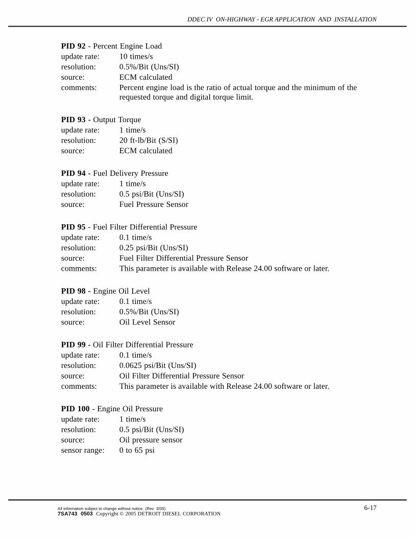
PID 92 - Percent Engine Loadupdate rate: 10 times/sresolution: 0.5%/Bit (Uns/SI)source: ECM calculatedcomments: Percent engine load is the ratio of actual torque and the minimum of the
requested torque and digital torque limit.
PID 93 - Output Torqueupdate rate: 1 time/sresolution: 20 ft-lb/Bit (S/SI)source: ECM calculated
PID 94 - Fuel Delivery Pressureupdate rate: 1 time/sresolution: 0.5 psi/Bit (Uns/SI)source: Fuel Pressure Sensor
PID 95 - Fuel Filter Differential Pressureupdate rate: 0.1 time/sresolution: 0.25 psi/Bit (Uns/SI)source: Fuel Filter Differential Pressure Sensorcomments: This parameter is available with Release 24.00 software or later.
PID 98 - Engine Oil Levelupdate rate: 0.1 time/sresolution: 0.5%/Bit (Uns/SI)source: Oil Level Sensor
PID 99 - Oil Filter Differential Pressureupdate rate: 0.1 time/sresolution: 0.0625 psi/Bit (Uns/SI)source: Oil Filter Differential Pressure Sensorcomments: This parameter is available with Release 24.00 software or later.
PID 100 - Engine Oil Pressureupdate rate: 1 time/sresolution: 0.5 psi/Bit (Uns/SI)source: Oil pressure sensorsensor range: 0 to 65 psi
All information subject to change without notice. (Rev. 3/05) 6-177SA743 0503 Copyright © 2005 DETROIT DIESEL CORPORATION

COMMUNICATION PROTOCOLS
PID 101 - Crankcase Pressureupdate rate: 1 time/sresolution: 0.125 psi/Bit (S/SI)source: Crankcase pressure sensorcomments: Some engine applications use a discrete switch in place of a full range sensor.
In these applications, the crankcase pressure data transmitted on the J1587data link is not a true representation of crankcase pressure.
PID 102 - Turbo Boost Pressure (Gage)update rate: 2 times/sresolution: 0.125 psi/Bit (Uns/SI)source: Turbo Boost Pressure Sensorcomments: Update rate is different that that specified by SAE (1 time/sec)
PID 103 - Turbo Speedupdate rate: 1 time/sresolution: 500 rpm/Bit (Uns/SI)source: Turbo Speed Sensor
PID 105 - Intake Manifold Temperatureupdate rate: 1 time/sresolution: 1 F/Bit (Uns/SI)source: Intake Manifold Temperature Sensor
PID 106 - Air Inlet Pressureupdate rate: 1 time/sresolution: 0.25 psi/Bit (Uns/SI)source: Air Inlet Pressure Sensor or Boost Pressure Sensor (Series 2000 and Series
4000 only before Release 21.0, Series 50 and Series 60 beginning withRelease 21.0)
PID 107 - Air Filter Differential Pressureupdate rate: 0.1 time/sresolution: 0.2 in.H2O/Bit (Uns/SI)source: Air Filter Differential Pressure Sensorcomments: This parameter is available with Release 24.00 software or later.
PID 108 - Barometric Pressureupdate rate: 1 time/sresolution: 0.0625 psi/Bit (Uns/SI)source: Barometric Pressure Sensor or ECM calculated
6-18 All information subject to change without notice. (Rev. 3/05)7SA743 0503 Copyright © 2005 DETROIT DIESEL CORPORATION

DDEC IV ON-HIGHWAY - EGR APPLICATION AND INSTALLATION
PID 109 - Coolant Pressureupdate rate: 1 time/sresolution: 0.125 psi/Bit (Uns/SI)source: Coolant Pressure Sensor
PID 110 - Coolant Temperatureupdate rate: 1 time/sresolution: 1 F/Bit (Uns/SI)source: Coolant Temperature Sensorsensor range: 0 to 300 F
PID 111 - Coolant Levelupdate rate: 10 times/sresolution: 0.5%/Bit (Uns/SI) (or full = 100%, low = 0%)source: Coolant Level Sensorcomments: If the Add Coolant Level Sensor (ACLS) is installed with the Engine
Protection Coolant Level Sensor (CLS), the coolant level will be:100% When both sensors are in coolant50% When the ACLS is out of the coolant0% When both sensors are out of the coolant
If only the CLS is configured:100% Full0% Low
PID 113 - Engine Governor Droopupdate rate: On request onlyresolution: 2 rpm/Bit (Uns/SI)source: Calibration value
PID 121 - Engine Retarder Statusupdate rate: 1 time/s (5 times/s when changing)format:
Bit: 1 1 - 2 cylinders activeBit: 2 1 - 3 cylinders activeBit: 3 1 - 4 cylinders activeBit: 4 1 - 6 cylinders activeBit: 5 1 - 8 cylinders activeBit: 8 1 - Retarder active
comments: Transmitted only if engine brakes are configured.
All information subject to change without notice. (Rev. 3/05) 6-197SA743 0503 Copyright © 2005 DETROIT DIESEL CORPORATION

COMMUNICATION PROTOCOLS
PID 122 - Engine Retarder Percentupdate rate: 1 time/sresolution: 0.5%Bit (Uns/SI)source: ECM calculatedcomments: This parameter is available with Release 5.00 or later
PID 351 (255 95) - Turbo Compressor Inlet Temperatureupdate rate: 1 time/sresolution: 1 F/Bit (Uns/SI)comments: This parameter is available with Rel 33.0 software or later.
PID 354 (255 98) - Relative Humidityupdate rate: Every 10 secondsresolution: 0.4%Bit (Uns/SI)comments: This parameter is available with Rel 33.0 software or later.
Double Byte Parameters
PID 147 - Average Fuel Economy — Natural Gasupdate rate: every 10 secondsresolution: 1/512 km/kg per bit (Uns/I)
PID 148 - Instantaneous Fuel Economy — Natural Gasupdate rate: 5 times/sresolution: 1/512 km/kg per bit (Uns/I)
PID 149 - Fuel Mass Flow Rate — Natural Gasupdate rate: 5 times/sresolution: 0.125 kg/hr per bit (Uns/I)
PID 153 - Crankcase Pressureupdate rate: 1 time/sresolution: 0.0078125 kPa/Bit (S/I)comments: Some engine applications use a discrete switch in place of a full range sensor.
In these applications, the crankcase pressure data transmitted on the J1587data link is not a true representation of crankcase pressure.This PID is used to provide crankcase pressure with better resolution thenthat provided with PID 101.This parameter is available with Release 3.00 software or later.
6-20 All information subject to change without notice. (Rev. 3/05)7SA743 0503 Copyright © 2005 DETROIT DIESEL CORPORATION

DDEC IV ON-HIGHWAY - EGR APPLICATION AND INSTALLATION
PID 154 - Auxiliary Input and Output status #2update rate: On requestformat:
PID Data154 a b
a - Auxiliary Input StatusBit: 1, 2 Torque/RPM Limiting Switch
00 - Off01 - On10 - Error Condition11 - Not Available
Bit: 4-3 Stop Engine Override Switch00 - Off01 - On10 - Error Condition11 - Not Available
Bit: 5, 6 A/C Disengaged00 - Off01 - On10 - Error Condition11 - Not Available
Bit: 8-7 Reservedb - Auxiliary Output Status
Bit: 1, 2 Fan Control #200 - Off01 - On10 - Error Condition11 - Not Available
Bit: 3, 4 ReservedBit: 5, 6 ReservedBit: 7, 8 Reserved
source: ECM calculated; outputs represent intended state
PID 155 - Auxiliary Input and Output status #1update rate: On requestformat:
PID Data154 a b
a - Auxiliary Input StatusBit:1, 2 Jake Brake Low Switch
00 - Off01 - On
All information subject to change without notice. (Rev. 3/05) 6-217SA743 0503 Copyright © 2005 DETROIT DIESEL CORPORATION

COMMUNICATION PROTOCOLS
10 - Error Condition11 - Not Available
Bit: 3, 4 Jake Brake Medium Switch00 - Off01 - On10 - Error Condition11 - Not Available
Bit: 5, 6 Idle Validation Switch00 - Off
01 - On
10 - Error Condition11 - Not Available
Bit: 7, 8 Throttle Inhibit Switch00 - Off01 - On10 - Error Condition11 - Not Available
b - Auxiliary Output StatusBit: 1, 2 Vehicle Power Shutdown
00 - Off01 - On10 - Error Condition11 - Not Available
Bit: 3, 4 Starter Lockout00 - Off01 - On10 - Error Condition11 - Not Available
Bit: 5, 6 Coolant Level Low Light00 - Off01 - On10 - Error Condition11 - Not Available
Bit: 7, 8 Fan Control #100 - Off01 - On10 - Error Condition11 - Not Available
source: ECM calculated; outputs represent intended state
6-22 All information subject to change without notice. (Rev. 3/05)7SA743 0503 Copyright © 2005 DETROIT DIESEL CORPORATION

DDEC IV ON-HIGHWAY - EGR APPLICATION AND INSTALLATION
PID 162 - Transmission Range Selectedupdate rate: 2 times/sformat: aa - Transmission Range Selected (ASCII)comments: Transmitted only when the transmission type is a Meritor ESS (17-22).
Characters sent will be 0, L, 1, 2, ..., 15. If only one character is required,the second character will be used and the first character will be a space.Whenever a target gear is not selected a "0" will be transmitted.
PID 163 - Transmission Range Attainedupdate rate: 2 times/sformat: aa - Transmission Range Attained (ASCII)comments: Transmitted only when the transmission type is a Meritor ESS (17-22).
Characters sent will be 0, L, 1, 2, ..., 15. If only one character is required,the second character will be used and the first character will be a space.Whenever a target gear is not selected a "0" will be transmitted.
PID 164 - Injection Control Pressureupdate rate: 1 time/sresolution: 1/256 MPa (Uns/I)source: Injection Pressure Sensor
PID 166 - Engine Horsepower Ratingupdate rate: On request onlyresolution: 1 bhp/Bit (Uns/I)source: Calibration value
PID 168 - Battery Voltageupdate rate: 1 time/sresolution: 0.05 volts/Bit (Uns/I)source: Battery voltage measured at input to ECMcomments: The ECM input battery voltage does fluctuate as injectors fire and will require
filtering if used for display purposes.
PID 171 - Ambient Air Temperatureupdate rate: 1 time/sresolution: 0.25 F/Bit (S/I)source: ECM estimated
All information subject to change without notice. (Rev. 3/05) 6-237SA743 0503 Copyright © 2005 DETROIT DIESEL CORPORATION

COMMUNICATION PROTOCOLS
PID 172 - Air Inlet Temperatureupdate rate: 1 time/sresolution: 0.25 F/Bit (S/I)source: Air Temperature Sensorsensor range: -40 to 175 F
PID 173 — Exhaust Temperature
update rate: 1 time/sec
resolution: 0.25 F/Bit (S/I)
PID 174 - Fuel Temperatureupdate rate: 1 time/sresolution: 0.25 F/Bit (S/I)source: Fuel Temperature Sensorsensor range: -40 to 175 F
PID 175 - Engine Oil Temperatureupdate rate: 1 time/sresolution: 0.25 F/Bit (S/I)source: Oil temperature sensorsensor range: -40 to 300 F
PID 182 - Trip Fuelupdate rate: 0.1 times/sresolution: 0.125 gal/Bit (Uns/I)source: ECM calculated
PID 183 - Fuel Rateupdate rate: 5 times/sresolution: 1/64 gal/hour/Bit (Uns/I)source: ECM calculated
PID 184 - Instantaneous Fuel Economy (MPG)update rate: 5 times/sresolution: 1/256 mpg/Bit (Uns/I)source: ECM calculatedcomments: Transmitted only if the Vehicle Speed Sensor is configured.
6-24 All information subject to change without notice. (Rev. 3/05)7SA743 0503 Copyright © 2005 DETROIT DIESEL CORPORATION

DDEC IV ON-HIGHWAY - EGR APPLICATION AND INSTALLATION
PID 185 - Average Fuel Economy (MPG)update rate: 0.1 times/sresolution: 1/256 mpg/Bit (Uns/I)source: ECM calculatedcomments: Trip information from DDEC requires that the Vehicle Speed Sensor is
enabled.
PID 187 - VSG Set Speedupdate rate: 0.1 times/s, 5 times per s when the set speed is changingresolution: 0.25 rpm/Bit (Uns/I)source: VSG switch inputcomments: Used to indicate the current set speed from:
Analog VSGCruise Switch VSGEngine Speed Cruise ControlPressure Governor Mode - RPM or pressureEngine Sync. Mode (marine applications)
PID 188 - Idle Set Speedupdate rate: On request onlyresolution: 0.25 rpm/Bit (Uns/I)source: Calibration value
PID 189 - Rated Engine Speedupdate rate: On request onlyresolution: 0.25 rpm/Bit (Uns/I)source: Calibration value
PID 190 - Engine Speedupdate rate: 10 times/sresolution: 0.25 rpm/Bit (Uns/I)source: ECM calculated
PID 191 - Transmission Output Shaft Speedupdate rate: 10 times/sresolution: 0.25 rpm/Bit (Uns/I)source: Transmitted when configured for Meritor ESS transmissions only.
PID 404 (255 148) - Turbo Compressor Out Temperatureupdate rate: 1 times/sresolution: 0.25 F/Bit (S/I)
All information subject to change without notice. (Rev. 3/05) 6-257SA743 0503 Copyright © 2005 DETROIT DIESEL CORPORATION

COMMUNICATION PROTOCOLS
PID 411 (255 155) - EGR Delta Pressureupdate rate: 1 time/sresolution: 0.0078125 kPa/Bit (S/I)comments: This parameter is available with Rel 33.0 software or later.
PID 412 (255 156) - EGR Temperatureupdate rate: 1 time/sresolution: 0.25 F/Bit (S/I)comments: This parameter is available with Rel 33.0 software or later.
PID 439 (255 183) - Extended Range Boost Pressureupdate rate: 1 time/sresolution: 0.125 kPa/Bit (UnS/I)comments: This parameter is available with Rel 36.0 software or later.
6-26 All information subject to change without notice. (Rev. 3/05)7SA743 0503 Copyright © 2005 DETROIT DIESEL CORPORATION
DDEC IV ON-HIGHWAY - EGR APPLICATION AND INSTALLATION
Variable Length Parameters
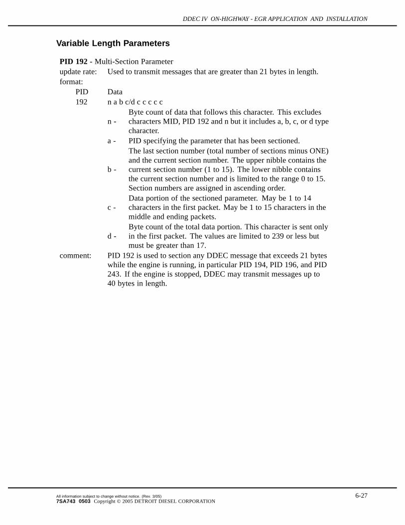
PID 192 - Multi-Section Parameterupdate rate: Used to transmit messages that are greater than 21 bytes in length.format:
PID Data192 n a b c/d c c c c c
n -Byte count of data that follows this character. This excludescharacters MID, PID 192 and n but it includes a, b, c, or d typecharacter.
a - PID specifying the parameter that has been sectioned.
b -
The last section number (total number of sections minus ONE)and the current section number. The upper nibble contains thecurrent section number (1 to 15). The lower nibble containsthe current section number and is limited to the range 0 to 15.Section numbers are assigned in ascending order.
c -Data portion of the sectioned parameter. May be 1 to 14characters in the first packet. May be 1 to 15 characters in themiddle and ending packets.
d -Byte count of the total data portion. This character is sent onlyin the first packet. The values are limited to 239 or less butmust be greater than 17.
comment: PID 192 is used to section any DDEC message that exceeds 21 byteswhile the engine is running, in particular PID 194, PID 196, and PID243. If the engine is stopped, DDEC may transmit messages up to40 bytes in length.
All information subject to change without notice. (Rev. 3/05) 6-277SA743 0503 Copyright © 2005 DETROIT DIESEL CORPORATION

COMMUNICATION PROTOCOLS
PID 194 - Transmitter System Diagnostic Code / Occurrence Count Tableupdate rate: On Request onlyformat:
PID Data194 n a b c a b c a b c a b c a b c...
n - Byte count of data that follows this character. This excludescharacters MID, PID 194 and n but includes a, b, c typecharacters.
a - SID or PID of a standard diagnostic code.
b - Diagnostic code character
Bits: 1-4 FMI of a standard diagnostic codeBit: 5 Byte (a) Identifier
1 - Byte (a) is a SID0 - Byte (a) is a PID
Bit: 6 Type of Diagnostic Code1 - standard diagnostic code0 - expansion diagnostic codes (PID/SIDfrom page 2)
Bit: 7 Current Status of Fault1 - fault is inactive0 - fault is active
Bit: 8 Occurrence count1 - count is included0 - count is not included
c - Occurrence count for the diagnostic code defined by thepreceding 2 characters. The maximum occurrence count is 255.Bit 8 of byte (b) of the diagnostic code is used to determine ifit is included.
source: ECM calculatedcomment: comments: Diagnostic codes are transmitted periodically while
active. When the active code becomes inactive, the code is transmittedonce to indicate that the fault became inactive. Inactive diagnosticcodes are available by request of PID 194. If more than 6 codes areactive at any point, PID 194 is sectioned as described in PID 192.
6-28 All information subject to change without notice. (Rev. 3/05)7SA743 0503 Copyright © 2005 DETROIT DIESEL CORPORATION

DDEC IV ON-HIGHWAY - EGR APPLICATION AND INSTALLATION
PID 196 - Diagnostic Data/count clear responseupdate rate: On Request onlyformat:
PID Data196 n a b c c c c c
n -Byte count of data that follows this character. This excludescharacters MID, PID 194 and n but includes a, b, and c typecharacters.
a - SID or PID of a standard diagnostic code
b - Diagnostic Code Character
Bits 1-4 - FMI of a standard diagnostic codeBit 5 - Byte (a) identifier
1 - Byte (a) is a SID0 - Byte (a) is a PID
Bit 6 - Type of diagnostic code1 - standard diagnostic code
0 -expansion diagnostic codes (PID/SID frompage 2)
Bit 7-8 - Action- Message is an ASCII descriptive message for
the given diagnostic code.01 - The count has been cleared for the given
diagnostic code.10 - All clearable diagnostic counts have been
cleared for this device.- Message is additional diagnostic information
for the given diagnostic code, as defined below.c = Additional information (if applicable)
c1-c5 - ATA/VMRS (DTDSC)c6, c7 - Engine hours the code was first logged (LSB first)
format: 1 h/Bit.range - 0-65535 hours.
c8, c9 - Calendar date (Month, Day) the code was first logged,if available.
c10, c11 - Clock time the code was first logged (hours, minutes),if available.
c12, c13 - Engine hours the code last became active (LSB first).c14, c15 - Calendar date (Month, Day) the code last became
active, if available.c16, c17 - Clock time the code last became active (hours, minutes),
if available.
All information subject to change without notice. (Rev. 3/05) 6-297SA743 0503 Copyright © 2005 DETROIT DIESEL CORPORATION

COMMUNICATION PROTOCOLS
PID 196 - Diagnostic Data/count clear responseupdate rate: On Request onlyformat:
PID Datac18, c19 - Number of ss the code has been active (LSB first).
format: ss = 1 s/Bitrange = 0-65535 (18.2 hours)Value remains at 65535 ss once it has been reached.
c20 - Number of Stop Engine Override Switch restarts whilethe code was active. The value remains at 255 onceit has been reached.
c21+ = Optional associated parameter value (scaled as definedin J1587)For temperatures, pressures, and voltages with FMI 0- Highest value achievedFor temperatures, pressures, and voltages with FMI 1- Lowest value achievedFor engine speed with FMI 0 - Highest speed achievedFor vehicle speed with FMI 0 or 11 - Highest speedachieved
Last byte = checksumsource: ECM calculated
comment:The date and time that the code last became inactive (bytes c14-c17) willbe transmitted as zero if the code is currently active. This data may besectioned using PID 192.
PID 228- Speed Sensor Calibrationupdate rate: On Request onlyformat:
PID Data228 n a a a a
n = number of bytes: 4a = Speed Sensor Calibration 1 pulse/mi (Uns/LI)
source: Calculated from calibration values
6-30 All information subject to change without notice. (Rev. 3/05)7SA743 0503 Copyright © 2005 DETROIT DIESEL CORPORATION

DDEC IV ON-HIGHWAY - EGR APPLICATION AND INSTALLATION
PID 229- Total Fuel — Natural Gasupdate rate: On Requestformat:
PID Data229 n a a a a
n = number of bytes: 4a = total fuel used
resolution: 0.5 kg per bit (Uns/LI)
PID 230- Total Idle Fuel Used — Natural Gasupdate rate: On Requestformat:
PID Data230 n a a a a
n = number of bytes: 4a = total fuel used
resolution: 0.5 kg per bit (Uns/LI)
PID 231- Trip Fuel — Natural Gasupdate rate: Every 10 secondsformat:
PID Data231 n a a a a
n = number of bytes: 4a = trip fuel
resolution: 0.5 kg per bit (Uns/LI)
PID 233- Unit Number (Power Unit)update rate: On Request onlyformat:
PID Data231 n a a a . . .
n = number of bytes: 10a = unit number in alphanumeric ASCII characters
comment: This parameter is available with Release 20.00 software or later
All information subject to change without notice. (Rev. 3/05) 6-317SA743 0503 Copyright © 2005 DETROIT DIESEL CORPORATION

COMMUNICATION PROTOCOLS
PID 234- Software Identificationupdate rate: On Request onlyformat:
PID Data234 n a a b c c
n = number of bytes: 5a = Major software release level in ASCIIb = ASCII "."b = Minor software release level in ASCII
Example: "01.05" is interpreted as Major release 1, Minor release 5source: ECM calculatedcomment: This parameter is available with Release 3.00 software or later
PID 235- Total Idle Hoursupdate rate: On Request onlyformat:
PID Data235 n a a a a
n = number of bytes: 4a = Total idle hours; scaled 0.05 hours/Bit (Uns/LI)
source: ECM calculatedcomment: Accumulates time while the engine is operating at idle.
PID 236- Total Idle Fuel Usedupdate rate: On Request onlyformat:
PID Data236 n a a a a
n = number of bytes: 4a = Idle fuel used; scaled 1/8 gallons/Bit (Uns/LI)
source: ECM calculatedcomment: Accumulates while the engine is operating at idle.
6-32 All information subject to change without notice. (Rev. 3/05)7SA743 0503 Copyright © 2005 DETROIT DIESEL CORPORATION

DDEC IV ON-HIGHWAY - EGR APPLICATION AND INSTALLATION
PID 237- Vehicle Identification Number (VIN)update rate: On Request onlyformat:
PID Data237 n a a a ...
n = number of bytes: up to 17a = VIN in ASCII characters
source: Calibration value
PID 240- Last Customer Calibration Change Hoursupdate rate: On Request onlyformat:
PID Data240 n a a a a
n = number of bytes: 4a = Last customer calibration change hours; scaled 0.05 h/Bit (Uns/LI)
source: ECM calculatedcomment: Used to identify the last customer reprogramming occurrence, stored in
engine hours.
PID 243- Device Identificationupdate rate: On Request onlyformat:
PID Data243 n a b b b b b c d d d d d d d d e f f f f f f f f f f
n = number of bytes: 26a = component ID = MIDb = ATA/VMRS manufacturer ID (5 bytes)c = delimiter: ASCII ‘*'d = engine model number (8 bytes)e = delimiter: ASCII ‘*'f = engine serial number (10 bytes)
source: Calibration valuecomment: This parameter may be sectioned using PID 192.
All information subject to change without notice. (Rev. 3/05) 6-337SA743 0503 Copyright © 2005 DETROIT DIESEL CORPORATION

COMMUNICATION PROTOCOLS
PID 244- Trip Milesupdate rate: 0.1 times/sformat:
PID Data244 n a a a a
n = number of bytes: 4a = trip miles 0.1 mile/Bit (Uns/LI)
source: ECM calculatedcomment: Transmitted only if the vehicle speed sensor is configured.
PID 245- Total Milesupdate rate: 0.1 times/sformat:
PID Data245 n a a a a
n = number of bytes: 4a = total miles, 0.1 mile/Bit (Uns/LI)
source: ECM calculatedcomment: Transmitted only if the vehicle speed sensor is configured.
PID 247- Total Engine Hoursupdate rate: On request onlyformat:
PID Data247 n a a a a
n = number of bytes: 4a = total engine hours 0.05 hour/Bit (Uns/LI)
source: ECM calculatedcomment: Used to identify the total hours that the engine is operating. Time
accumulated while the engine speed is above 60 rpm.
6-34 All information subject to change without notice. (Rev. 3/05)7SA743 0503 Copyright © 2005 DETROIT DIESEL CORPORATION

DDEC IV ON-HIGHWAY - EGR APPLICATION AND INSTALLATION
PID 248- Total VSG Hoursupdate rate: On request onlyformat:
PID Data248 n a a a a
n = number of bytes: 4b = total VSG hours 0.05 hour/Bit (Uns/LI)
source: ECM calculatedcomment: Used to identify total engine hours the engine is operating in the following
modes:-Hand throttle VSG-High idle using cruise switches-Pressure governor mode: either RPM or pressure
PID 249- Total Engine Revolutionsupdate rate: On request onlyformat:
PID Data249 n a a a a
n = number of bytes: 4a = total engine revolutions 1000 revolutions/Bit (Uns/SI)
comment: This parameter is available with Release 20.00 software or later
PID 250- Total Fuel Usedupdate rate: On request onlyformat:
PID Data250 n a a a a
n = number of bytes: 4a = total fuel used 0.125 gal/Bit (Uns/LI)
source: ECM calculated
All information subject to change without notice. (Rev. 3/05) 6-357SA743 0503 Copyright © 2005 DETROIT DIESEL CORPORATION

COMMUNICATION PROTOCOLS
PID 251- Clockupdate rate: On request onlyformat:
PID Data251 n a b c
n = number of bytes: 3a = Seconds 0.25 sec/Bit, range 0 to 59.75 secondsb = Minutes 1.0 min/Bit, range 0 to 59 minutesc = Hours 1.00 hour/Bit, range 0 to 23 hours
comment: Transmitted if clock data is considered valid. The time is broadcast inGreenwich Mean Time. This parameter is available with Release 20.00software or later.
PID 252- Dateupdate rate: On request onlyformat:
PID Data252 n a b c
n = number of bytes: 3a = Day 0.25 day/Bit, range 1 to 31.75 daysb = Month 1.0 month/Bit, range 1 to 12 monthsc = Year - 1985 1.00 year/Bit, range 0 to 99
comment: Day of the month is scaled such that 0 is a null value, values 1, 2, 3, and 4are the first day of the month, 5, 6, 7, 8,are the second day of the month,etc. Transmitted if clock data is considered valid. This parameter isavailable with Release 20.00 software or later.
6-36 All information subject to change without notice. (Rev. 3/05)7SA743 0503 Copyright © 2005 DETROIT DIESEL CORPORATION

DDEC IV ON-HIGHWAY - EGR APPLICATION AND INSTALLATION
6.3 SAE J1922
Circuits 800 (Data Link +) and 801 (Data Link-) as shown on the communications harnessschematic are used as the J1922 communication link.
6.3.1 MESSAGE FORMAT
A complete description of the DDEC IV parameters is provided within this section of the manual.DDEC IV transmits parametric data at SAE J1922 recommended rates in packed messageform. The first byte or character of each J1922 message is the Message Identification Character(MID). The MID is used to identify the source of a data transmission and identify the type ofdata being transmitted.
6.3.2 SAE J1922 PARAMETERS AVAILABLE WITH DDEC IV
DDEC IV supports the J1922 message identifiers (MIDs) listed in Table 6-5.
MID Description69 Engine to powertrain message
70 Engine to powertrain initialization message
74 Transmission to powertrain message
76 Transmission to powertrain initialization request message
79 ABS/traction control to powertrain message
81 ABS/traction control to powertrain initialization request message
83 Retarder to powertrain message
84 Retarder to powertrain initialization message
Table 6-5 SAE J1922 MIDs Supported by DDEC
6.3.3 SAE J1922 MIDS
The following sections identify the MIDs supported by DDEC.
All information subject to change without notice. (Rev. 3/05) 6-377SA743 0503 Copyright © 2005 DETROIT DIESEL CORPORATION

COMMUNICATION PROTOCOLS
Engine to Powertrain
Byte 1 069 MID - Engine to powertrainByte 2 --- Percent torque value scaled 1% of peak torque/Bit - S/SI
Byte 3 ---Accelerator pedal position scaled 0.392%/Bit (100/255%/Bit) -Uns/SI
Byte 4 --- Control/status byteBit 1 Cruise control status
1: cruise control active0: cruise control inactive
Bit 2 VSG control status1: VSG active0: VSG inactive
Bit 3 Road speed limit status1: road speed limit active0: road speed limit inactive
Bit 4 Retarder control status1: engine retarder enabled0: engine retarder not enabled
Bit 5 AP kickdown switch1: in kickdown position0: not in kickdown position
Bit 6 AP low idle switch1: in low idle position0: not in low idle position
Bit 7 Engine parameter changeBit 8 Reserved
1: parameters have changed0: current parameters valid
Byte 5 --- Engine's desired RPM scaled 16 rpm/Bit - Uns/SIByte 6 --- Desired RPM asymmetry adjustment scaled as a ratio - Uns/SIByte 7 --- Checksum
If either the transmission messages or the ABS messages are enabled, DDEC shall transmitthis message 20 times per second.
6-38 All information subject to change without notice. (Rev. 3/05)7SA743 0503 Copyright © 2005 DETROIT DIESEL CORPORATION
DDEC IV ON-HIGHWAY - EGR APPLICATION AND INSTALLATION
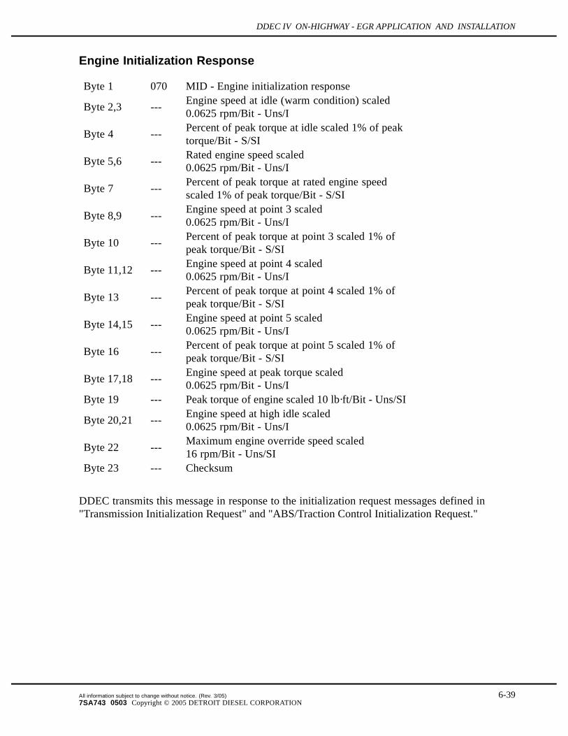
Engine Initialization Response
Byte 1 070 MID - Engine initialization response
Byte 2,3 ---Engine speed at idle (warm condition) scaled0.0625 rpm/Bit - Uns/I
Byte 4 ---Percent of peak torque at idle scaled 1% of peaktorque/Bit - S/SI
Byte 5,6 ---Rated engine speed scaled0.0625 rpm/Bit - Uns/I
Byte 7 ---Percent of peak torque at rated engine speedscaled 1% of peak torque/Bit - S/SI
Byte 8,9 ---Engine speed at point 3 scaled0.0625 rpm/Bit - Uns/I
Byte 10 ---Percent of peak torque at point 3 scaled 1% ofpeak torque/Bit - S/SI
Byte 11,12 ---Engine speed at point 4 scaled0.0625 rpm/Bit - Uns/I
Byte 13 ---Percent of peak torque at point 4 scaled 1% ofpeak torque/Bit - S/SI
Byte 14,15 ---Engine speed at point 5 scaled0.0625 rpm/Bit - Uns/I
Byte 16 ---Percent of peak torque at point 5 scaled 1% ofpeak torque/Bit - S/SI
Byte 17,18 ---Engine speed at peak torque scaled0.0625 rpm/Bit - Uns/I
Byte 19 --- Peak torque of engine scaled 10 lb·ft/Bit - Uns/SI
Byte 20,21 ---Engine speed at high idle scaled0.0625 rpm/Bit - Uns/I
Byte 22 ---Maximum engine override speed scaled16 rpm/Bit - Uns/SI
Byte 23 --- Checksum
DDEC transmits this message in response to the initialization request messages defined in"Transmission Initialization Request" and "ABS/Traction Control Initialization Request."
All information subject to change without notice. (Rev. 3/05) 6-397SA743 0503 Copyright © 2005 DETROIT DIESEL CORPORATION

COMMUNICATION PROTOCOLS
Transmission to Powertrain Message
Byte 1 074 MID - transmission to powertrainByte 2 --- Control/status byte
Bit 1,2 Override control mode00: override disabled01: engine speed control10: engine torque control11: engine speed/torque limit
Bit 3 Retarder enable1: enable retarder0: disable retarder
Bit 4 Momentary high idle enable1: override enabled0: override disabled
Bit 5 Driveline engaged (ignored by DDEC)1: driveline engaged0: driveline disengaged
Bit 6 Transmission retarder status (ignored by DDEC)1: retarder active0: retarder inactive
Bit 7,8 ReservedByte 3 --- When mode is as follows
00: Not broadcast01: Desired engine speed (LSB)scaled 0.0625 rpm/Bit - Uns/I10: Not broadcast11: Engine speed upper limitscaled 16 rpm /Bit - Uns/SI
Byte 4 --- When mode00: Not broadcast01: Desired engine speed (MSB) - scaled 0.0625 rpm/Bit - Uns/I10: Desired torque value scaled 1% of peak torque/Bit - S/SI11: Percent torque upper limit scaled 1% of peak torque/Bit - S/SI
Byte 5 --- Output shaft speed scaled 16 rpm/Bit - Uns/SIByte 6 --- Checksum
The desired speed request requires a zero droop operation, regardless of the droop calibrated foreither the rated speed governor or the VSG governor. While the transmission is requesting anoverride control mode other than override disabled (00), the messages are expected to be repeatedon a continuous basis. DDEC will maintain the most recent requested control mode until a requestto disable override (00) is received or a timeout period has elapsed without any request from thetransmission, at which point DDEC will revert to its normal (override disabled) state.
6-40 All information subject to change without notice. (Rev. 3/05)7SA743 0503 Copyright © 2005 DETROIT DIESEL CORPORATION

DDEC IV ON-HIGHWAY - EGR APPLICATION AND INSTALLATION
Requests to disable the retarder (Bit 3 of byte 2) and override momentary high idle (Bit 4 of byte2) follow the same strategy. DDEC will maintain the most recent requested state until a newrequest is received or a timeout period has elapsed without any request from the transmission.The default state for the retarder is enabled and for override momentary high idle is disabled.
NOTE:This message has a variable length.
Transmission Initialization Request
Byte 1 076 MID - transmission initialization requestByte 2 Status/enable byte
Bit 1 1 = request engine initialization message
Bit 21 = request trans. initialization message (ignoredby DDEC)
Bit 31 = request ABS initialization message (ignoredby DDEC)
Bit 4 1 = request retarder initialization messageBit 5-7 ReservedBit 8 1 = progressive shift disable
Byte 3 --- Checksum
If enabled, DDEC responds to this request with the initialization messages defined in "EngineInitialization Response" and "Retarder Initialization Response" as appropriate. Once a progressiveshift indication (allow or disallow) is transmitted, this state is maintained until a subsequentrequest from the transmission changes the state or a new ignition cycle begins.
All information subject to change without notice. (Rev. 3/05) 6-417SA743 0503 Copyright © 2005 DETROIT DIESEL CORPORATION

COMMUNICATION PROTOCOLS
ABS/Traction Control To Powertrain
Byte 1 079 MID - ABS/Traction control to powertrainByte 2 --- Control/status byte
Bit 1,2 Override control mode00: override disabled01: engine speed control10: engine torque control11: engine torque limit
Bit 3 Retarder or engine control select1: retarder control0: engine fueling control
Bit 4 Gear shift disable (ignored by DDEC)1: Inhibit gear shifts0: allow shifts
Bit 5 Retarder disable1: disable retarders0: enable retarders
Bit 6Torque converter lock up disable (ignored byDDEC)1: disable lock up clutch0: enable lock up clutch
Bit 7 Request to neutral (ignored by DDEC)1: request de-clutch to neutral0: allow normal operation
Bit 8 ReservedByte 3 --- When mode is as follows:
00: Not broadcast01: Desired engine speed value scaled 16 rpm/Bit- Uns/SI10: Desired % peak torque value scaled 1% ofpeak torque/Bit - S/SI11: Percent torque upper limit scaled 1% of peaktorque/Bit - S/SI
Byte 4 --- Checksum
While the traction control system is requesting a override control mode other than overridedisabled (00), the messages are expected to be repeated on a continuous basis. DDEC willmaintain the most recent requested engine control mode and/or retarder control mode until arequest to disable override (00) is received or a timeout period has elapsed without any requestfrom the traction control system, at which point DDEC will revert to its normal (overridedisabled) state.
6-42 All information subject to change without notice. (Rev. 3/05)7SA743 0503 Copyright © 2005 DETROIT DIESEL CORPORATION

DDEC IV ON-HIGHWAY - EGR APPLICATION AND INSTALLATION
Requests to disable the retarder (Bit 5 of byte 2) follow the same strategy. DDEC will maintain themost recent requested state until a new request is received or a timeout period has elapsed withoutany request from the traction control system. The default state for the retarder is enabled. Theretarder request is honored independent of the particular control select (Bit 3 of byte 2) in effect.
NOTE:The retarder disable request applies to all retarder types; external engine retarder, DDECcontrolled engine retarder, and transmission retarder.
DDEC will ignore requests from the ABS system when the transmission type is a Meritor ESSand the transmission is performing a shift.
DDEC will honor requests for both retarder control (Bit 3 of byte 2 = 1) and engine control (Bit3 of byte 2 = 0). For retarder control, the percent of peak torque request will be translated intoengine brake low, medium and high as follows:
0% no braking or disable retarder1% to 33%: low braking34% to 66%: medium braking67% to 100%: high braking
Low, medium and high braking modes only apply when DDEC controls the engine brake directly.A request of 0% torque may apply to either direct engine brake control by DDEC or indirectengine brake control.
NOTE:This message has a variable length.
ABS/Traction Control Initialization Request
Byte 1 081 MID - ABS/Traction control initialization requestByte 2 --- Status/enable byte
Bit 1 1 = request engine initialization message
Bit 21 = request transmission initialization message (ignoredby DDEC)
Bit 31 = request ABS initialization message (ignored byDDEC)
Bit 4 1 = request retarder initialization messageBit 5-8 Reserved
Byte 3 --- Checksum
If enabled, DDEC responds to this request with the initialization messages defined in "EngineInitialization Response" and "Retarder Initialization Response" as appropriate.
All information subject to change without notice. (Rev. 3/05) 6-437SA743 0503 Copyright © 2005 DETROIT DIESEL CORPORATION

COMMUNICATION PROTOCOLS
Retarder to Powertrain
Byte 1 083 MID - Retarder to powertrainByte 2 --- Retarder status byte
Bit 1 Retarder active/inactive1: retarder active0: retarder inactive
Bit 2 Retarder operational status1: retarder selected0: not selected
Bit 3,4 For future useBit 5-8 Retarding level status
0000: Off0101: Active in low (33%)1010: Active in medium (66%)1111: Active in high (100%)
Byte 3 --- Checksum
If either the transmission messages or the ABS/ASR messages are enabled and digital outputsare configured for DDEC controlled engine brake operation, DDEC shall transmit this message10 times per second.
Retarder Initialization Response
Byte 1 084 MID - Retarder initialization responseByte 2 --- Type of retarder
Bit 1 Reserved - sent as 0Bit 2 1 = Engine compression releaseBit 3-7 Not applicable for DDEC - sent as 0Bit 8 Reserved - sent as 0
Byte 3 --- Peak torque of retarder (10 lb·ft/Bit) - Uns/SIByte 4 --- Checksum
If either the transmission messages or the ABS/ASR messages are enabled and digital outputsare configured for DDEC controlled engine brake operation, DDEC transmits this message inresponse to the initialization request messages defined in "Transmission Initialization Request"and "ABS/Traction Control Initialization Request."
6-44 All information subject to change without notice. (Rev. 3/05)7SA743 0503 Copyright © 2005 DETROIT DIESEL CORPORATION

DDEC IV ON-HIGHWAY - EGR APPLICATION AND INSTALLATION
6.4 SAE J1939
Circuits 925 (CAN_H/J1939 [+]), 926 (CAN_L/J1939 [-]) and 927 (CAN_SHLD/J1939 Shield)as shown on the communications harness schematic are used as the J1939 communication link.See Figure 6-1.
Figure 6-1 Communication Harness
6.4.1 MESSAGE FORMATThe message format uses the parameter group number as the label for a group of parameters.Each of the parameters within the group can be expressed in ASCII, as scaled data, or as functionstates consisting of one or more Bits. Alphanumeric data will be transmitted with the mostsignificant byte first. Other parameters consisting of two or more data bytes shall be transmittedleast significant byte first. The type of data is also identified for each parameter.
The following sections identify the parameters that are supported by DDEC, parameter groupnumber response definations (refer to section 6.4.2) and parameter group number commanddefinitions (refer to section 6.4.3).
All information subject to change without notice. (Rev. 3/05) 6-457SA743 0503 Copyright © 2005 DETROIT DIESEL CORPORATION

COMMUNICATION PROTOCOLS
6.4.2 SAE J1939/71 APPLICATION LAYER
The Application Layer Parameter Group Number (PGN) response definitions are describedin the following sections.
Electronic Engine Controller #1 – EEC1
Transmission Rate: Engine Speed DependentData Length: 8 bytesData Page: 0PDU format: 240PDU specific: 4Default priority: 3PGN: 61,444 (0x00F004)Byte : 1 Status_EEC1
Bits: 8-5 Not DefinedBits: 4-1 Engine / Retarder Torque Mode (SPN 899)
0000: Low Idle Governor/No Request (Default Mode)0001: Accelerator Pedal/Operator Selection0010: Cruise Control0011: PTO Governor0100: Road Speed Governor0101: ASR Control0110: Transmission Control0111: ABS Control1000: Torque Limiting1001: High Speed Governor1010: Braking System1011: Remote Accelerator - N/A1100: Not Defined1101: Not Defined1110: Other1111: Not Available
Byte: 2 Drivers Demand Engine - Pct Torque (SPN 512)Resolution: 1% / Bit, -125% offset
Byte: 3 Actual Engine - Percent Torque (SPN 513)Resolution: 1% / Bit, -125% offset
Bytes: 4,5 Engine Speed (SPN 190)Resolution: 0.125 rpm / Bit, 0 rpm offset
Byte: 6 Source address of controlling device for engine control (SPN 1483)Byte: 7 Bits: 8–5 Not Defined
Bits: 1–4 Engine Starter Mode – N/AByte: 8 Engine Demand–Percent Torque – N/A
6-46 All information subject to change without notice. (Rev. 3/05)7SA743 0503 Copyright © 2005 DETROIT DIESEL CORPORATION

DDEC IV ON-HIGHWAY - EGR APPLICATION AND INSTALLATION
Electronic Engine Controller #2 – EEC2
Transmission Rate : 50 msData Length: 8 bytesData Page: 0PDU format: 240PDU specific: 3Default priority: 3PGN: 61,443 (0x00F003)Byte: 1 Status_EEC2
Bits: 8-5 Not Defined (Transmitted as 1111)Bits: 4-3 AP Kickdown Switch (SPN 559)
00: Kickdown Passive01: Kickdown Active11: Not Configured
Bits: 2,1 AP Low Idle Switch (SPN 558)00: Not In Low Idle Condition01: In Low Idle Condition10: Error Detected11: Not Configured
Byte: 2 Accelerator Pedal Position (TPS) (SPN 91)Resolution: 0.4% / Bit, 0% offset
Byte: 3 Percent Load At Current Speed (SPN 92)Resolution: 1% / Bit, 0% offset
Byte: 4 Remote Accelerator–N/ABytes: 5-8 Not Defined
Idle Operation — IO
Transmission Rate : On RequestData Length: 8 bytesData Page: 0PDU format: 254PDU specific: 220Default priority: 6PGN: 65,244 (0x00FEDC)Bytes: 1-4 Total Idle Fuel Used (SPN 236)
Resolution: 0.5 L / Bit, 0 L offsetBytes: 5-8 Total Idle Hours (SPN 235)
Resolution: 0.05 hr / Bit, 0 hr offset
All information subject to change without notice. (Rev. 3/05) 6-477SA743 0503 Copyright © 2005 DETROIT DIESEL CORPORATION

COMMUNICATION PROTOCOLS
Turbocharger — TC
Transmission Rate : 1 secData Length: 8 bytesData Page: 0PDU format: 254PDU specific: 221Default priority: 6PGN: 65, 245 (0x00FEDD)Byte: 1 Turbo Oil Pressure - N/ABytes: 2,3 Turbo Speed (SPN 103)
Resolution: 4 rpm / Bit, 0 rpm offsetByte: 4 Bits: 8–7 Turbo Oil Level Switch–N/A
Bits: 6–1 Not DefinedBytes: 5-8 Not Defined
Electronic Engine Controller #3 – EEC3
Transmission Rate : 250 msData Length: 8 bytesData Page: 0PDU format: 253PDU specific: 211Default priority: 6PGN: 65,247 (0x00FEDF)Byte: 1 Nominal Friction - Percent Torque (SPN 514)
Resolution: 1% / Bit, -125% offsetBytes: 2,3 Engine's Desired Operating Speed (SPN 515)
Resolution: 0.125 rpm / Bit, 0 rpm offsetByte 4: Engine's Desired Operating Speed Asymmetry Adjustment (SPN
519)ratio 0 to 250
Byte: 5Engine Controlled Cooling Fan Losses — Percent Torque (SPN2978)Resolution:NOTE:
1%/Bit, -125% offsetRelease 32.0 or later
Bytes: 6–8 Not Defined
6-48 All information subject to change without notice. (Rev. 3/05)7SA743 0503 Copyright © 2005 DETROIT DIESEL CORPORATION

DDEC IV ON-HIGHWAY - EGR APPLICATION AND INSTALLATION
Vehicle Distance — VD
Transmission Rate : On RequestData Length: 8 bytesData Page: 0PDU format: 254PDU specific: 224Default priority: 6PGN: 65,248 (0x00FEE0)Bytes: 1-4 Trip Distance (SPN 244)
Resolution: 0.125 km / Bit, 0 km offsetBytes: 5-8 Total Vehicle Distance (SPN 245)
Resolution: 0.125 km / Bit, 0 km offset
Idle Shutdown — Shutdown
Transmission Rate : 1 secData Length: 8 bytesData Page: 0PDU format: 254PDU specific: 228Default priority: 6PGN: 65,252 (0x00FEE4)Byte: 1 Idle shutdown_1
Bits: 8,7 Idle Shutdown Timer State (SPN 590)00: Inactive01: Active
Bits: 6,5 Idle Shutdown Timer Override (SPN 592)00: Inactive01: Active
Bits: 4,3 Driver Alert Mode (SPN 594)00: Inactive01: Active
Bits: 2,1Engine Has Shutdown by Idle Shutdown (SPN593)00: Engine has not shutdown by idle shutdown01: Engine has shutdown by idle shutdown
Byte: 2 Idle shutdown_2Bits: 8,7 Idle Shutdown Timer Function (SPN 591)
00: Disabled in Calibration01: Enabled in Calibration
Bits: 6-1 Not DefinedByte: 3 Bits: 8,7 Not Defined
All information subject to change without notice. (Rev. 3/05) 6-497SA743 0503 Copyright © 2005 DETROIT DIESEL CORPORATION

COMMUNICATION PROTOCOLS
Bits: 6,5 Refrigerant High Pressure Switch- N/ABits: 4,3 Refrigerant Low Pressure Switch- N/ABits: 2,1 A/C High Pressure Fan Switch-N/A
Byte: 4 Lamp_commands - N/AByte: 5 Engine Shutdown_1 (SPN 1107)
Bits: 8,7 Engine Protection Shutdown Timer State00:Timer not Active01:Timer Active
Bits: 6,5 Engine Protection Shutdown Override (SPN 1108)00:Override Off01:Override On
Bits: 4,3 Engine Shutdown Approaching - N/A
Bits: 2,1Engine Has Shutdown By Engine ProtectionSystem (SPN 1110)00:Not Shutdown01:Has Shutdown
Byte: 6 Engine Shutdown_2Bits: 8,7 Engine Protection System Configured (SPN 1111)
00:Not Enabled In Calibration01:Enabled In Calibration
Bits: 6-1 Not DefinedBytes: 7-8 Not Defined
Engine Hours, Revolutions — Hours
Transmission Rate : On RequestData Length: 8 bytesData Page: 0PDU format: 254PDU specific: 229Default priority: 6PGN: 65,253 (0x00FEE5)Bytes: 1-4 Total Engine Hours (SPN 247)
Resolution: 0.05 h / Bit, 0 h offsetBytes: 5-8 Total Engine Revolutions (SPN 249)
Resolution: 1000 revs / Bit, 0 revs offset
6-50 All information subject to change without notice. (Rev. 3/05)7SA743 0503 Copyright © 2005 DETROIT DIESEL CORPORATION

DDEC IV ON-HIGHWAY - EGR APPLICATION AND INSTALLATION
Time/Date — TD
Transmission Rate : On RequestData Length: 8 bytesData Page: 0PDU format: 254PDU specific: 230Default priority: 6PGN: 65,254 (0x00FEE6)Byte: 1 Seconds (SPN 959)
Resolution: 0.25 sec / Bit, 0 sec offsetByte: 2 Minutes (SPN 960)
Resolution: 1 min / Bit, 0 min offsetByte: 3 Hours (SPN 961)
Resolution: 1 hour / Bit, 0 h offsetByte: 4 Month (SPN 963)
Resolution: 1 month / Bit, 0 month offsetByte: 5 Day (see Note) (SPN 962)
Resolution: 0.25 day / Bit, 0 day offsetByte: 6 Year (SPN 964)
Resolution: 1 year / Bit, 1985 year offsetByte: 7 Local Minute Offset – N/AByte: 8 Local Hour Offset – N/A
Note:The Day field represents days elapsed (e.g. 1/1/98 at 12:00 amwould be 0 for byte 5 (Day) and 1/1/98 at 1:00 pm would be 2 forbyte 5 and 1/15/98 at 1:00 pm would be 62 for byte 5).
Vehicle Hours — VH
Transmission Rate : On RequestData Length: 8 bytesData Page: 0PDU format: 254PDU specific: 231Default priority: 6PGN: 65,255 (0x00FEE7)Bytes: 1-4 Total Vehicle Hours -N/ABytes: 5-8 Total Power Takeoff Hours (SPN 248)
Resolution: 0.05 h / Bit, 0 h offset
All information subject to change without notice. (Rev. 3/05) 6-517SA743 0503 Copyright © 2005 DETROIT DIESEL CORPORATION
COMMUNICATION PROTOCOLS
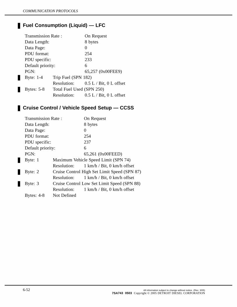
Fuel Consumption (Liquid) — LFC
Transmission Rate : On RequestData Length: 8 bytesData Page: 0PDU format: 254PDU specific: 233Default priority: 6PGN: 65,257 (0x00FEE9)Byte: 1-4 Trip Fuel (SPN 182)
Resolution: 0.5 L / Bit, 0 L offsetBytes: 5-8 Total Fuel Used (SPN 250)
Resolution: 0.5 L / Bit, 0 L offset
Cruise Control / Vehicle Speed Setup — CCSS
Transmission Rate : On RequestData Length: 8 bytesData Page: 0PDU format: 254PDU specific: 237Default priority: 6PGN: 65,261 (0x00FEED)Byte: 1 Maximum Vehicle Speed Limit (SPN 74)
Resolution: 1 km/h / Bit, 0 km/h offsetByte: 2 Cruise Control High Set Limit Speed (SPN 87)
Resolution: 1 km/h / Bit, 0 km/h offsetByte: 3 Cruise Control Low Set Limit Speed (SPN 88)
Resolution: 1 km/h / Bit, 0 km/h offsetBytes: 4-8 Not Defined
6-52 All information subject to change without notice. (Rev. 3/05)7SA743 0503 Copyright © 2005 DETROIT DIESEL CORPORATION

DDEC IV ON-HIGHWAY - EGR APPLICATION AND INSTALLATION
Engine Temperature #1— ET1
Transmission Rate : 1 secData Length: 8 bytesData Page: 0PDU format: 254PDU specific: 238Default priority: 6PGN: 65,262 (0x00FEEE)Byte: 1 Engine Coolant Temperature (SPN 110)
Resolution: 1 C / Bit, -40 C offsetByte: 2 Fuel Temperature (SPN 174)
Resolution: 1 C / Bit, -40 C offsetBytes: 3,4 Engine Oil Temperature (SPN 175)
Resolution: 0.03125 C / Bit, -273 C offsetBytes: 5,6 Turbo Oil Temperature -N/AByte: 7 Engine Intercooler Temperature (SPN 52)
Resolution: 1 C / Bit, -40 C offsetByte 8: Engine Intercooler Thermostat Opening–N/A
Engine Fluid Level/Pressure #1 — EFL/P1
Transmission Rate : 0.5 secData Length: 8 bytesData Page: 0PDU format: 254PDU specific: 239Default priority: 6PGN: 65,263 (0x00FEEF)Byte: 1 Fuel Delivery Pressure (SPN 94)
Resolution: 4 kPa / Bit, 0 kPa offsetByte: 2 Extended Crankcase Blowby Pressure–N/AByte: 3 Engine Oil Level (SPN 98)
Resolution: 0.4% / Bit, 0% offsetByte: 4 Engine Oil Pressure (SPN 100)
Resolution: 4 kPa / Bit, 0 kPa offsetByte: 5,6 Crankcase Pressure (SPN 101)
Resolution: 0.0078125 kPa / Bit (1/128 kPa / Bit), -250 kPa offsetByte: 7 Coolant Pressure (SPN 109)
Resolution: 2 kPa / Bit, 0 kPa offsetByte: 8 Coolant Level (SPN 111)
Resolution: 0.4% / Bit, 0% offset
All information subject to change without notice. (Rev. 3/05) 6-537SA743 0503 Copyright © 2005 DETROIT DIESEL CORPORATION

COMMUNICATION PROTOCOLS
Power Takeoff Information — PTO
Transmission Rate : 100 msData Length: 8 bytesData Page: 0PDU format: 254PDU specific: 240Default priority: 6PGN: 65,264 (0x00FEF0)Byte: 1 Power Takeoff Oil Temperature - N/AByte: 2,3 Power Takeoff Speed - N/AByte: 4,5 Power Takeoff Set Speed (SPN 187)
Resolution: 0.125 rpm / Bit, 0 rpm offsetByte: 6 Measured_PTO_1
Bits: 8,7 Not DefinedBits: 6,5 Remote PTO Variable Speed Control Switch - N/A
Bits: 4,3Remote PTO Preprogrammed Speed ControlSwitch (SPN 979)00: Switch Off01: Switch On11: Not Configured
Bits: 2,1 PTO Enable Switch (SPN 980)00: Switch Off01: Switch On11: Not Configured
Byte: 7 Measured_PTO_2Bits: 8,7 PTO Accelerate Switch (SPN 981)
00: Switch Off01: Switch On11: Not Configured
Bits: 6,5 PTO Resume Switch (SPN 982)00: Switch Off01: Switch On11: Not Configured
Bits: 4,3 PTO Coast/Decelerate Switch (SPN 983)00: Switch Off01: Switch On11: Not Configured
Bits: 2,1 PTO Set Switch (SPN 984)00: Switch Off01: Switch On11: Not Configured
Byte: 8 Not Defined
6-54 All information subject to change without notice. (Rev. 3/05)7SA743 0503 Copyright © 2005 DETROIT DIESEL CORPORATION

DDEC IV ON-HIGHWAY - EGR APPLICATION AND INSTALLATION
Cruise Control / Vehicle Speed — CCVS
Transmission Rate : 100 msData Length: 8 bytesData Page: 0PDU format: 254PDU specific: 241Default priority: 6PGN: 65,265 (0x00FEF1)Byte: 1 Measured_SW1
Bits: 8,7 Not DefinedBits: 6,5 Cruise Control Pause Switch–N/ABits: 4,3 Parking Brake Switch (SPN 70)
00: Park Brake Not Set01: Park Brake Set11: Not Configured
Bits: 2,1 Two Speed Axle Switch - N/A.Byte: 2,3 Wheel Based Vehicle Speed (SPN 84)
Resolution:1/256 km/h / Bit, 0 km/h offset (1/412 mph / Bit,0 mph offset)
Byte: 4 Measured_CC_SW1Bits: 8,7 Clutch Switch (SPN 598)
00: Clutch Pedal Released01: Clutch Pedal Depressed10: Error11: Not Configured
Bits: 6,5 Brake Switch (SPN 597)00: Brake Pedal Released01: Brake Pedal Depressed11: Not Configured
Bits: 4,3 Cruise Control Enable Switch (SPN 596)00: Cruise Control Disabled01: Cruise Control Enabled10: Error11: Not Configured
Bits: 2,1 Cruise Control Active(SPN 595)00: Cruise Control Off01: Cruise Control On11: Not Configured
Byte: 5 Measured _CC_SW2Bits: 8,7 Cruise Control Accelerate Switch (SPN 602)
00: Accelerate Switch Off01: Accelerate Switch On
All information subject to change without notice. (Rev. 3/05) 6-557SA743 0503 Copyright © 2005 DETROIT DIESEL CORPORATION

COMMUNICATION PROTOCOLS
10: Error11: Not Configured
Bits: 6,5 Cruise Control Resume Switch (SPN 601)00: Resume Switch Off01: Resume Switch On10: Error11: Not Configured
Bits: 4,3 Cruise Control Coast Switch (SPN 600)00: Coast Switch Off01: Coast Switch On10: Error11: Not Configured
Bits: 2,1 Cruise Control Set Switch (SPN 599)00: Set Switch Off01: Set Switch On10: Error11: Not Configured
Byte: 6 Cruise Control Set Speed (SPN 86)Resolution: 1 km/h / Bit, 0 km/h offset
Byte: 7 State_CCBits: 8–6 Cruise Control State (SPN 527)
000: Off/Disabled001: Hold010: Accelerate011: Decelerate/Coast100: Resume101: Set110: Accelerator Override111: Not Available
Bits: 5-1 PTO State (SPN 976)00000: Off/Disabled00001: Hold (PTO Mode is ActiveNote: Rel 38.0 or later
Byte: 8 Measured_idle_SW1Bits: 8,7 Engine Shutdown Override Switch (SPN 1237)
00: Off01: On11: Not ConfiguredNote: Rel 36.0 or later
Bits: 6,5 Engine Test Mode Switch - N/ABits: 4,3 Idle Decrement Switch - N/ABits: 2,1 Idle Increment Switch - N/A
6-56 All information subject to change without notice. (Rev. 3/05)7SA743 0503 Copyright © 2005 DETROIT DIESEL CORPORATION

DDEC IV ON-HIGHWAY - EGR APPLICATION AND INSTALLATION
Fuel Economy (Liquid) – LFE
Transmission Rate : 100 msData Length: 8 bytesData Page: 0PDU format: 254PDU specific: 242Default priority: 6PGN: 65,266 (0x00FEF2)Bytes: 1,2 Fuel Rate (SPN 183)
Resolution: 0.05 L/h / Bit, 0 L/h offsetBytes: 3,4 Instantaneous Fuel Economy (SPN 184)
Resolution: 1/512 km/L / Bit, 0 km/L offsetBytes: 5,6 Average Fuel Economy (SPN 185)
Resolution: 1/512 km/L / Bit, 0 km/L offset
Bytes: 7Throttle Plate Position (Natural Gas) (SPN 51)Resolution: 0.4%/bit, 0% offsetNote: Rel 36.0 or later
Bytes: 8 Not Defined
Ambient Conditions – AMB
Transmission Rate : 1 secData Length: 8 bytesData Page: 0PDU format: 254PDU specific: 245Default priority: 6PGN: 65,269 (0x00FEF5)Byte: 1 Barometric Pressure (SPN 108)
Resolution: 0.5 kPa / Bit, 0 kPa offsetByte: 2 Cab Interior Temperature - N/ABytes: 4,5 Ambient Air Temperature (SPN 171)
Resolution: 0.03125 C / Bit, -273 C offsetByte: 6 Air Inlet Temperature (SPN 172)
Resolution: 1 C / Bit, -40 C offsetBytes: 7,8 Road Surface Temperature - N/A
All information subject to change without notice. (Rev. 3/05) 6-577SA743 0503 Copyright © 2005 DETROIT DIESEL CORPORATION

COMMUNICATION PROTOCOLS
Inlet / Exhaust Conditions – IC
Transmission Rate : 0.5 secData Length: 8 bytesData Page: 0PDU format: 254PDU specific: 246Default priority: 6PGN: 65,270 (0x00FEF6)Byte: 1 Particulate Trap Inlet Pressure - N/AByte 2: Boost Pressure (SPN 102)
Resolution: 2 kPa / Bit, 0 kPa offsetByte 3: Intake Manifold Temperature (SPN 105)
Resolution: 1 C / Bit, -40 C offsetByte 4: Air Inlet Pressure (SPN 106)
Resolution: 2 kPa / Bit, 0 kPa offsetByte 5: Air Filter Differential Pressure (SPN 107)
Resolution: 0.05 kPa / Bit, 0 kPa offsetBytes: 6,7 Exhaust Gas Temperature (SPN 173)
Resolution: 0.03125 C / Bit, -273 C offsetByte: 8 Coolant Filter Differential Pressure - N/A
Turbocharger Information #6 – TCI6
Note: Rel 36.0 or laterTransmission Rate : 1 secData Length: 8 bytesData Page: 0PDU format: 253PDU specific: 211Default priority: 6PGN: 64,979 (0x00FDD3)Bytes: 1,2 Turbocharger Compressor Outlet #1 Temperature (SPN 2629)
Resolution: 0.03125 C/bit, —273 C offsetBytes: 3,4 Turbocharger Compressor Outlet #2 Temperature – N/ABytes: 5,6 Turbocharger Compressor Outlet #3 Temperature – N/ABytes: 7,8 Turbocharger Compressor Outlet #4 Temperature – N/A
6-58 All information subject to change without notice. (Rev. 3/05)7SA743 0503 Copyright © 2005 DETROIT DIESEL CORPORATION

DDEC IV ON-HIGHWAY - EGR APPLICATION AND INSTALLATION
Exhaust Port Temperature #1 – EPT1
Transmissionrate:
1 sec
Data Length: 8 bytes
Data Page: 0
PDU Format: 254
PDU Specific 163
Default Priority: 7
PGN: 65,187 (Ox00FEA3)
Byte: 1, 2 Exhaust Gas Port 1 Temperature (SPN 1137)Resolution: 0.03125 C/bit, –273 C offset
Byte: 3, 4 Exhaust Gas Port 2 Temperature (SPN 1138)Resolution: 0.03125 C/bit, –273 C offset
Byte: 5, 6 Exhaust Gas Port 3 Temperature (SPN 1139)Resolution: 0.03125 C/bit, –273 C offset
Byte: 7, 8 Exhaust Gas Port 4 Temperature (SPN 1140)Resolution: 0.03125 C/bit, –273 C offset
Exhaust Port Temperature #2 – EPT2
TransmissionRate:
1 sec
Data Length: 8 bytes
Data Page: 0
PDU Format: 254
PDU Specific: 162
Default Priority: 7
PGN: 65,186 (Ox00FEA2)
Bytes: 1, 2 Exhaust Gas Port 5 Temperature (SPN 1141)Resolution: 0.03125 C/bit, –273 C offset
Byte: 3, 4 Exhaust Gas Port 6 Temperature (SPN 1142)Resolution: 0.03125 C/bit, –273 C offset
Byte: 5, 6 Exhaust Gas Port 7 Temperature (SPN 1143)Resolution: 0.03125 C/bit, –273 C offset
Byte: 7, 8 Exhaust Gas Port 8 Temperature (SPN 1144)Resolution: 0.03125 C/bit, –273 C offset
All information subject to change without notice. (Rev. 3/05) 6-597SA743 0503 Copyright © 2005 DETROIT DIESEL CORPORATION

COMMUNICATION PROTOCOLS
Exhaust Port Temperature #3 – EPT3
TransmissionRate:
1 sec
Data Length: 8 bytes
Data Page: 0
PDU Format: 254
PDU Specific: 161
Default Priority: 7
PGN: 65,185 (Ox00FEA1)
Byte: 1, 2 Exhaust Gas Port 9 Temperature (SPN 1145)Resolution: 0.03125 C/bit, –273 C offset
Byte: 3, 4 Exhaust Gas Port 10 Temperature (SPN 1146)Resolution: 0.03125 C/bit, –273 C offset
Byte: 5,6 Exhaust Gas Port 11 Temperature (SPN 1147)Resolution: 0.03125 C/bit, –273 C offset
Byte: 7, 8 Exhaust Gas Port 12 Temperature (SPN 1148)Resolution: 0.03125 C/bit, –273 C offset
Exhaust Port Temperature #4 – EPT4
TransmissionRate:
1 sec
Data Length: 8 bytes
Data Page: 0
PDU Format: 254
PDU Specific: 160
Default Priority: 7
PGN: 65, 184 (Ox00FEA0)
Byte: 1, 2 Exhaust Gas Port 13 Temperature (SPN 1149)Resolution: 0.03125 C/bit, –273 C offset
Byte: 3, 4 Exhaust Gas Port 14 Temperature (SPN 1150)Resolution: 0.03125 C/bit, –273 C offset
Byte: 5, 6 Exhaust Gas Port 15 Temperature (SPN 1151)Resolution: 0.03125 C/bit, –273 C offset
Byte: 7, 8 Exhaust Gas Port 16 Temperature (SPN 1152)Resolution: 0.03125 C/bit, –273 C offset
6-60 All information subject to change without notice. (Rev. 3/05)7SA743 0503 Copyright © 2005 DETROIT DIESEL CORPORATION

DDEC IV ON-HIGHWAY - EGR APPLICATION AND INSTALLATION
Vehicle Electrical Power – VEP
Transmission Rate : 1 secData Length: 8 bytesData Page: 0PDU format: 254PDU specific: 247Default priority: 6PGN: 65,271 (0x00FEF7)Byte: 1 Net Battery Current - N/AByte: 2 Alternator Current - N/ABytes: 3,4 Alternator Potential (voltage) - N/ABytes: 5,6 Electrical Potential (voltage) (SPN 168)
Resolution: 0.05 V / Bit, 0 V offsetBytes: 7,8 Battery Potential (Voltage), Switched - N/A
Alternate Fuel #1 – A1
Transmission Rate : 500 msData Length: 8 bytesData Page: 0PDU format: 254PDU specific: 253Default priority: 6PGN: 65,277 (0x00FEFD)Byte: 1 Blower Bypass Valve Position (SPN 72)
Resolution: 0.4% / Bit, 0% offsetBytes: 2,3 Gas Supply Pressure (SPN 159)
Resolution: 0.5 kPa/bit, 0 kPa offfsetNote: Rel 36.0 or later
Bytes: 4-8 Not Defined
All information subject to change without notice. (Rev. 3/05) 6-617SA743 0503 Copyright © 2005 DETROIT DIESEL CORPORATION

COMMUNICATION PROTOCOLS
Auxiliary Water Pump Pressure – AWPP
Transmission Rate : 1 secData Length: 8 bytesData Page: 0PDU format: 254PDU specific: 254Default priority: 6PGN: 65,278 (0x00FEFE)Byte: 1 Auxiliary Pump Pressure (SPN 73)
Resolution: 16 kPa / Bit, 0 kPa offsetByte: 2-8 Not Defined
Engine Fluid Level/Pressure #2 – EFL/P2
Transmission Rate : 500 msData Length: 8 bytesData Page: 0PDU format: 254PDU specific: 219Default priority: 6PGN: 65,243 (0x00FEDB)Bytes: 1,2 Injection Control Pressure - N/ABytes: 3,4 Injector Metering Rail Pressure (SPN 157)
Resolution: 1/256 MPa / Bit, 0 MPa offsetBytes: 5,6 Injector Timing Rail 1 Pressure–N/ABytes: 7,8 Injector Metering Rail 2 Pressure–N/A
High Resolution Vehicle Distance – VDHR
Transmission Rate : 1 secData Length: 8 bytesData Page: 0PDU format: 254PDU specific: 193Default priority: 6PGN: 65,217 (0x00FEC1)Bytes: 1-4 High Resolution Total Vehicle Distance (SPN 917)
Resolution: 5 m / Bit, 0 m offset (16.4 ft/Bit, 0 ft offset)Bytes: 5-8 High Resolution Trip Distance (SPN 918)
Resolution: 5 m / Bit, 0 m offset (16.4 ft/Bit, 0 ft offset)
6-62 All information subject to change without notice. (Rev. 3/05)7SA743 0503 Copyright © 2005 DETROIT DIESEL CORPORATION

DDEC IV ON-HIGHWAY - EGR APPLICATION AND INSTALLATION
Electronic Engine Controller #4 – EEC4
Transmission Rate : On RequestData Length: 8 bytesData Page: 0PDU format: 254PDU specific: 190Default priority: 6PGN: 65,214 (0x00FEBE)Bytes: 1,2 Rated Engine Power (SPN 166)
Resolution:0.5 kW / Bit, 0 kW offset (0.67 hp / Bit, 0 hpoffset)
Bytes: 3,4 Rated Engine Speed (SPN 189)Resolution: 0.125 rpm / Bit, 0 rpm offset
Bytes: 5-8 Not Defined
All information subject to change without notice. (Rev. 3/05) 6-637SA743 0503 Copyright © 2005 DETROIT DIESEL CORPORATION

COMMUNICATION PROTOCOLS
Fan Drive – FD
Transmission Rate : 1 secData Length: 8 bytesData Page: 0PDU format: 254PDU specific: 189Default priority: 6PGN: 65,213 (0x00FEBD)Byte: 1 Estimated Percent Fan Speed (SPN 975)
Resolution: 0.4% / Bit, 0% offsetByte: 2 State_Fan_Drive
Bits: 8-5 Not DefinedBits: 4-1 Fan Drive State (SPN 977)
0000: Fan Off0001: Engine System - General0010: Excessive Engine Air Temperature0011: Excessive Engine Oil Temperature0100: Excessive Engine Coolant Temperature0101-1000: Not Defined1001: Manual Control1010: Transmission Retarder1011: A/C System1100: Timer1101: Engine Brake1110: Other1111: Not Available
Bytes: 3,4 Fan Speed N/ABytes: 5-8 Not Defined
6-64 All information subject to change without notice. (Rev. 3/05)7SA743 0503 Copyright © 2005 DETROIT DIESEL CORPORATION

DDEC IV ON-HIGHWAY - EGR APPLICATION AND INSTALLATION
Electronic Retarder Controller #1 - ERC1
Transmission Rate : 100 msData Length: 8 bytesData Page: 0PDU format: 240PDU specific: 0Default priority: 6PGN: 61,440 (0x00F000)Byte : 1 Status_ERC1
Bits: 8,7 Retarder Enable - Shift Assist Switch - N/ABits: 6,5 Retarder Enable - Brake Assist Switch - N/ABits: 4-1 Engine/Retarder Torque Mode (SPN 900)
0000: No Request (Default Mode)0001: Accelerator Pedal/Operator Selection0010: Cruise Control0011: PTO Governor0100: Road Speed Governor - N/A0101: ASR Control
0110: Transmission Control
0111: ABS Control1000: Torque Limiting - N/A1001: High Speed Governor - N/A1010: Braking System1011: Remote Accelerator - N/A1100: Not Defined1101: Not Defined1110: Other1111: Not Available
Byte: 2 Actual Retarder - Percent Torque (SPN 520)Resolution: 1% / Bit, -125% offset
Byte: 3 Intended Retarder Percent Torque - N/AByte: 4 Coolant Load Increase
Bits: 8–5 Not DefinedBits: 3,4 Retarder Requesting Brake Light–N/ABits: 1,2 Engine Coolant Load Increase–N/A
Byte: 5 Source address of controlling device for retarder control (SPN 1480)Byte: 6 Drivers Demand Retarder–Percent Torque–N/AByte: 7 Retarder Selection, non-engine–N/AByte: 8 Actual Maximum Available Retarder–Percent Torque–N/A
All information subject to change without notice. (Rev. 3/05) 6-657SA743 0503 Copyright © 2005 DETROIT DIESEL CORPORATION

COMMUNICATION PROTOCOLS
Software Identification – SOFT
Transmission Rate : On RequestData Length: 30 bytesData Page: 0PDU format: 254PDU specific: 218Default priority: 6PGN: 65,242 (0x00FEDA)Byte: 1 Number of Software Identification Fields - 7Byte: 2 1st digit of Cal Major Version - ASCIIByte: 3 2nd digit of Cal Major Version - ASCIIByte: 4 3rd digit of Cal Major Version - ASCIIByte: 5 * - DelimiterByte: 6 1st digit of Cal Minor Version - ASCIIByte: 7 2nd digit of Cal Minor Version - ASCIIByte: 8 3rd digit of Cal Minor Version - ASCIIByte: 9 * - DelimiterByte: 10 1st Digit of Cal Edit Version - ASCIIByte: 11 2nd Digit of Cal Edit Version - ASCIIByte: 12 3rd Digit of Cal Edit Version - ASCIIByte: 13 * - DelimiterByte: 14 1st Digit of Edit Build Version - ASCIIByte: 15 2nd Digit of Edit Build Version - ASCIIByte: 16 3rd Digit of Edit Build Version - ASCIIByte: 17 * - DelimiterByte: 18 Software Release Type - ASCII
X - ExperimentalT - Pre-productionR - Production
Byte: 19 * - Delimiter
Byte: 20DDEC Hardware Version - ASCII3 – DDEC III, 4 – DDEC IV, 5 – DDEC V
Byte 21: * - DelimiterBytes: 22-29 ECM Serial Number - ASCIIByte: 30 * - Delimiter
6-66 All information subject to change without notice. (Rev. 3/05)7SA743 0503 Copyright © 2005 DETROIT DIESEL CORPORATION

DDEC IV ON-HIGHWAY - EGR APPLICATION AND INSTALLATION
Component Identification – CI
Transmission Rate : On RequestData Length: 37 bytesData Page: 0PDU format: 254PDU specific: 235Default priority: 6PGN: 65,259 (0x00FEEB)Bytes: 1-5 DTDSC - ASCIIByte: 6 * - DelimiterByte: 7-14 Engine Model Number - ASCIIByte: 15 * - DelimiterByte: 16-25 Engine Serial Number - ASCIIByte: 26 * - DelimiterByte: 27-36 Unit Number (VIN) - ASCIIByte: 37 * - Delimiter
All information subject to change without notice. (Rev. 3/05) 6-677SA743 0503 Copyright © 2005 DETROIT DIESEL CORPORATION

COMMUNICATION PROTOCOLS
Retarder Configuration – RC
Transmission Rate : 5 sec or upon receipt of a destination specific requestData Length: 19 bytesData Page: 0PDU format: 254PDU specific: 225Default priority: 6PGN: 65,249 (0x00FEE1)Byte: 1 Type And Location
Bits: 8-5 Retarder Location (SPN 902)0000: Primary Engine Retarder For CompressionBrakes0001: Primary Engine Retarder For Exhaust Brakes
Bits: 4-1 Retarder Type (SPN 901)0011: Compression Release (Engine Retarder)0100: Exhaust
Byte: 2 Retarder Control Method (SPN 557)255 - when not configured0 - DVB1 - Konstantdrossel2 - Low/High Compression3 - Low/Med/High Compression
Bytes: 3, 4 Retarder Speed At Idle, Point 1- N/AByte: 5 Percent Torque At Idle, Point 1 - N/ABytes: 6, 7 Maximum Retarder Speed, Point 2 - N/AByte: 8 Percent Torque At Maximum Speed, Point 2 - N/ABytes: 9, 10 Retarder Speed At Point 3 - N/AByte: 11 Percent Torque At Point 3 - N/ABytes: 12, 13 Retarder Speed At Point 4 - N/AByte: 14 Percent Torque At Point 4 - N/ABytes: 15,16 Retarder Speed At Peak Torque, Point 5 - N/ABytes: 17,18 Reference Retarder Torque - N/ABytes: 19 Percent Torque At Peak Torque, Point 5 - N/A
Engine Configuration – EC
Transmission Rate : 5 sec, on change of torque/speed points of morethan 10% since last transmission, or upon receiptof a destination specific request.
Data Length: 34 bytesData Page: 0PDU format: 254
6-68 All information subject to change without notice. (Rev. 3/05)7SA743 0503 Copyright © 2005 DETROIT DIESEL CORPORATION

DDEC IV ON-HIGHWAY - EGR APPLICATION AND INSTALLATION
PDU specific: 227Default priority: 6PGN: 65,251 (0x00FEE3)Bytes: 1,2 Engine Speed At Idle, Point 1 (SPN 188)
Resolution: 0.125 rpm / Bit, 0 rpm offsetByte: 3 Percent Torque At Idle, Point 1 (SPN 539)
Resolution: 1% / Bit, -125% offsetBytes: 4, 5 Engine Speed At Point 2 (SPN 528)
Resolution: 0.125 rpm / Bit, 0 rpm offsetByte: 6 Percent Torque At Point 2 (SPN 540)
Resolution: 1% / Bit, -125% offsetBytes: 7,8 Engine Speed At Point 3 (SPN 529)
Resolution: 0.125 rpm / Bit, 0 rpm offsetByte: 9 Percent Torque At Point 3 (SPN 541)
Resolution: 1% / Bit, -125% offsetBytes: 10, 11 Engine Speed At Point 4 (SPN 530)
Resolution: 0.125 rpm / Bit, 0 rpm offsetByte: 12 Percent Torque At Point 4 (SPN 542)
Resolution: 1% / Bit, -125% offsetBytes: 13, 14 Engine Speed At Point 5 (SPN 531)
Resolution: 0.125 rpm / Bit, 0 rpm offsetByte: 15 Percent Torque At Point 5 (SPN 543)
Resolution: 1% / Bit, -125% offsetBytes: 16, 17 Engine Speed At High Idle, Point 6 (SPN 532)
Resolution: 0.125 rpm / Bit, 0 rpm offsetBytes: 18, 19 (KP) Of Endspeed Governor - N/ABytes: 20, 21 Reference Engine Torque (SPN 544)
Resolution: 1 Nm / Bit, 0 Nm offsetByte: 22, 23 Maximum Momentary Engine Override Speed, Point 7 (SPN 533)
Resolution: 0.125 rpm / Bit, 0 rpm offsetByte: 24 Maximum Momentary Engine Override Time Limit (SPN 534)
Resolution: 0.1 s / Bit, 0 s offset
Byte: 25Requested Speed Control Range Lower Limit - 300 RPM (SPN535)Resolution: 10 rpm / Bit, 0 rpm offset
Byte: 26 Requested Speed Control Range Upper Limit (SPN 536)Resolution: 10 rpm / Bit, 0 rpm offset
Byte: 27 Requested Torque Control Range Lower Limit (SPN 537)Resolution: 1% / Bit, -125% offset
Byte: 28 Requested Torque Control Range Upper Limit (SPN 538)Resolution: 1 % / Bit, -125% offset
All information subject to change without notice. (Rev. 3/05) 6-697SA743 0503 Copyright © 2005 DETROIT DIESEL CORPORATION

COMMUNICATION PROTOCOLS
Bytes: 29–30Extended Range Requested Speed Control Range Upper Limit(SPN 1712)Note: Rel 36.0 or laterResolution: 0.125 rpm/bit, 0 rpm offset
Bytes: 31–32 Engine Moment of Inertia (SPN1794)Resolution: 0.004 kgm2/bit, 0 kgm2 offsetNote: Rel 36.0 or later
Bytes: 33–34 Default Engine Torque Limit – N/A
Adaptive Cruise Control – ACC1
Reception rate : 100 msData length: 8 bytesData Page: 0PDU format: 254PDU specific: 111PGN: 65135 (0x00FE6F)Byte : 1 Speed of Forward Vehicle - N/AByte : 2 Distance to Forward Vehicle - N/AByte : 3 Adaptive Cruise Control Set Speed - N/AByte : 4 ACC Status 1
Bits: 8,7 Not DefinedBits: 6-4 Adaptive Cruise Control Set Distance Mode - N/ABits: 3-1 Adaptive Cruise Control State
110: Error111: Not Available
Byte : 5 Road Curvature - N/AByte : 6 Not DefinedByte : 7 Bits: 8,7 Not Defined
Bits: 5,6 ACC Distance Alert Signal–N/ABits: 3,4 ACC System Shutoff Warning–N/ABits: 1,2 ACC Target Detected–N/A
Byte : 8 Not Defined
Note:This message is received only from an ACC device. It is nottransmitted by the ECM.
6-70 All information subject to change without notice. (Rev. 3/05)7SA743 0503 Copyright © 2005 DETROIT DIESEL CORPORATION

DDEC IV ON-HIGHWAY - EGR APPLICATION AND INSTALLATION
Torque Speed Control — TSC1
Reception Rate : 10 msData Length: 8 bytesData Page: 0PDU format: 0PDU specific: Destination AddressDefault priority: 3PGN: 0 (0x000000)Byte : 1 Control Bits
Bits: 8,7 Not DefinedBits: 6,5 Override Control Mode Priority (SPN 897)
00: Highest01: High10: Medium11: Low
Bits: 4,3 Requested Speed Control Conditions - N/ABits: 2,1 Override Control Modes (SPN 695)
00: Override Disabled01: Speed Control10: Torque Control11: Speed/Torque Limit
Byte: 2,3 Requested Speed / Speed Limit (SPN 898)Resolution: 0.125 rpm / Bit, 0 rpm offset
Byte: 4 Requested Torque / Torque Limit (SPN 518)Resolution: 1% / Bit, -125% offset
0-125% for engine torque requests-125-0% for retarder torque requests
Bytes: 5-8 Not Defined
All information subject to change without notice. (Rev. 3/05) 6-717SA743 0503 Copyright © 2005 DETROIT DIESEL CORPORATION

COMMUNICATION PROTOCOLS
Electronic Transmission Controller #1 – ETC1
Reception Rate : 10 msData Length: 8 bytesData Page: 0PDU format: 240PDU specific: 2Default priority: 3PGN: 61,442 (0x00F002)Byte : 1 Status_ETC1
Bits: 8,7 Not DefinedBits: 6,5 Shift in Progress (SPN 574)
00: shift is not in process01: shift in process11: N/A
Bits: 4,3 Torque Converter Lockup Engaged (SPN 573)00: Torque Converter Lockup Disengaged01: Torque Converter Lockup EngagedNote: Rel 38.0 or later
Bits: 2,1 Driveline Engaged00: Driveline Disengaged01: Driveline Engaged11: N/A
Byte: 2,3 Output Shaft Speed (SPN 191)Resolution: 0.125 rpm / Bit, 0 rpm offset
Byte: 4 Percent Clutch Slip - N/AByte: 5 Command_ETC1
Bits: 8-5 Not DefinedBits: 4-3 Progressive Shift Disabled (SPN 607)
00: Progressive Shift Is Not Disabled01: Progressive Shift Is Disabled11: N/A
Bits: 2,1 Momentary Engine Overspeed Enable (SPN 606)00: Momentary Engine Overspeed Is Disabled01: Momentary Engine Overspeed Is Enabled11: N/A
Bytes: 6,7 Input Shaft Speed - N/A
Byte: 8Source Address of Controlling Device for TransmissionControl–N/A
6-72 All information subject to change without notice. (Rev. 3/05)7SA743 0503 Copyright © 2005 DETROIT DIESEL CORPORATION

DDEC IV ON-HIGHWAY - EGR APPLICATION AND INSTALLATION
6.4.3 SAE J1939/21 DATA LINK LAYER
The Data Link Layer Parameter Group number (PGN) response definitions are described inthe following sections.
Acknowledge / Negative Acknowledge – ACK/NACK
Transmission Rate:
As Needed
Data Length: 8 bytesData Page: 0PDU format: 232PDU specific: Destination AddressDefault priority: 6PGN: 59, 392 (0x00E800)Byte : 1 Control Byte
0: Positive Acknowledgment (ACK)1: Negative Acknowledgment (NACK)2: Access Denied (PGN supported but access denied)
Byte: 2 Group Function Value (if applicable)- N/ABytes: 3-5 Not DefinedBytes: 6 Least Significant Byte of PGN of Requested InformationByte: 7 Middle Byte of PGN of Requested InformationByte: 8 Most Significant Byte of PGN of Requested Information
All information subject to change without notice. (Rev. 3/05) 6-737SA743 0503 Copyright © 2005 DETROIT DIESEL CORPORATION

COMMUNICATION PROTOCOLS
Requests
Transmission Rate : As NeededData Length: 3 bytesData Page: 0PDU format: 234PDU specific: Destination AddressDefault priority: 6PGN: 59,904 (0x00EA00)Byte : 1 Least Significant Byte of PGNByte: 2 Byte 2 of PGNByte: 3 Most Significant Byte of PGN
NOTE:It is recommended that requests occur no more than 2 or 3 times per second.
NOTE:For any unsupported PGN that are destination specific DDEC will transmit a NACK.DDEC will not transmit a NACK to a global request.
Transport Protocol Broadcast Announce (TP.CM_BAM)
Transmission Rate: As Required
Data Length: 8 bytes
Data Page: 0
PDU Format: 236
PDU Specific: 255
Default Priority: 7
Byte: 1 Control Byte — set to 32 for CM_BAM
Byte: 2, 3 Total Message Size, number of bytes
Byte: 4 Total number of packets
Byte: 5 Not Defined
Byte: 6–8 PGN of packeted message
6-74 All information subject to change without notice. (Rev. 3/05)7SA743 0503 Copyright © 2005 DETROIT DIESEL CORPORATION
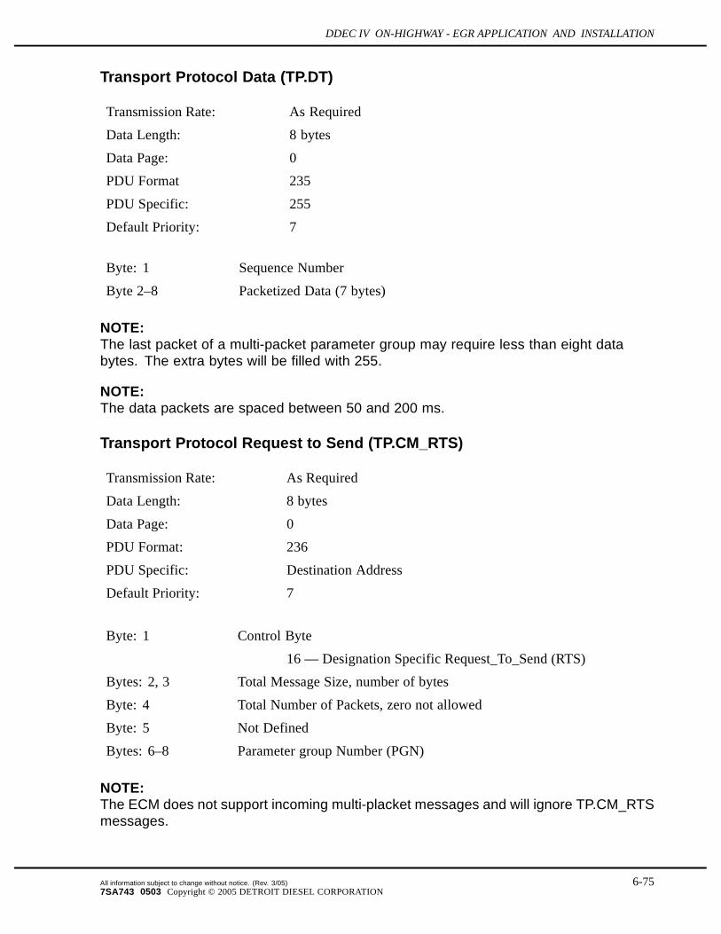
DDEC IV ON-HIGHWAY - EGR APPLICATION AND INSTALLATION
Transport Protocol Data (TP.DT)
Transmission Rate: As Required
Data Length: 8 bytes
Data Page: 0
PDU Format 235
PDU Specific: 255
Default Priority: 7
Byte: 1 Sequence Number
Byte 2–8 Packetized Data (7 bytes)
NOTE:The last packet of a multi-packet parameter group may require less than eight databytes. The extra bytes will be filled with 255.
NOTE:The data packets are spaced between 50 and 200 ms.
Transport Protocol Request to Send (TP.CM_RTS)
Transmission Rate: As Required
Data Length: 8 bytes
Data Page: 0
PDU Format: 236
PDU Specific: Destination Address
Default Priority: 7
Byte: 1 Control Byte
16 — Designation Specific Request_To_Send (RTS)
Bytes: 2, 3 Total Message Size, number of bytes
Byte: 4 Total Number of Packets, zero not allowed
Byte: 5 Not Defined
Bytes: 6–8 Parameter group Number (PGN)
NOTE:The ECM does not support incoming multi-placket messages and will ignore TP.CM_RTSmessages.
All information subject to change without notice. (Rev. 3/05) 6-757SA743 0503 Copyright © 2005 DETROIT DIESEL CORPORATION
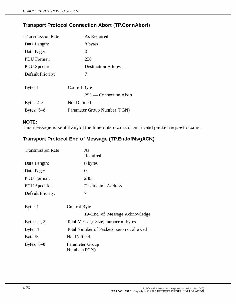
COMMUNICATION PROTOCOLS
Transport Protocol Connection Abort (TP.ConnAbort)
Transmission Rate: As Required
Data Length: 8 bytes
Data Page: 0
PDU Format: 236
PDU Specific: Destination Address
Default Priority: 7
Byte: 1 Control Byte
255 — Connection Abort
Byte: 2–5 Not Defined
Bytes: 6–8 Parameter Group Number (PGN)
NOTE:This message is sent if any of the time outs occurs or an invalid packet request occurs.
Transport Protocol End of Message (TP.EndofMsgACK)
Transmission Rate: AsRequired
Data Length: 8 bytes
Data Page: 0
PDU Format: 236
PDU Specific: Destination Address
Default Priority: 7
Byte: 1 Control Byte
19–End_of_Message Acknowledge
Bytes: 2, 3 Total Message Size, number of bytes
Byte: 4 Total Number of Packets, zero not allowed
Byte 5: Not Defined
Bytes: 6–8 Parameter GroupNumber (PGN)
6-76 All information subject to change without notice. (Rev. 3/05)7SA743 0503 Copyright © 2005 DETROIT DIESEL CORPORATION

DDEC IV ON-HIGHWAY - EGR APPLICATION AND INSTALLATION
Transport Protocol Clear to Send (TP.CM_CTS)
Transmission Rate: As Required
Data Length: 8 bytes
Data Page: 0
PDU Format: 236
PDU Specific: Destination Address
Default Priority: 7
Byte: 1 Control Byte
17 — Destination Specific Clear_to_Send (CTS)
Byte: 2 Number of packets that can be sent
Byte: 3 Next packet number to be sent
Bytes: 4-5 Not Defined
Bytes: 6-8 Parameter Group Number (PGN)
Transport Protocol Data (TP.DT)
Transmission Rate: As Required
Data Length: 8 bytes
Data Page: 0
PDU Format 235
PDU Specific: Destination Address
Default Priority: 7
Byte: 1 Sequence Number
Bytes: 2–8 Packetized Data (7 Bytes)
NOTE:The last packet of a multi-packet parameter group may require less than eighty databytes. The extra bytes will be filled with 255.
The data packets will be spaced no more tha 200 ms.
All information subject to change without notice. (Rev. 3/05) 6-777SA743 0503 Copyright © 2005 DETROIT DIESEL CORPORATION
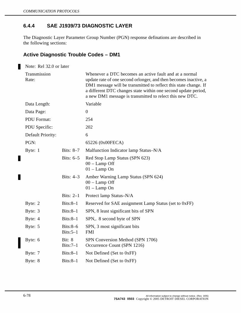
COMMUNICATION PROTOCOLS
6.4.4 SAE J1939/73 DIAGNOSTIC LAYER
The Diagnostic Layer Parameter Group Number (PGN) response definations are described inthe following sections:
Active Diagnostic Trouble Codes – DM1
Note: Rel 32.0 or later
TransmissionRate:
Whenever a DTC becomes an active fault and at a normalupdate rate of one second orlonger, and then becomes inactive, aDM1 message will be transmitted to reflect this state change. Ifa different DTC changes state within one second update period,a new DM1 message is transmitted to relect this new DTC.
Data Length: Variable
Data Page: 0
PDU Format: 254
PDU Specific: 202
Default Priority: 6
PGN: 65226 (0x00FECA)
Byte: 1 Bits: 8–7 Malfunction Indicator lamp Status–N/A
Bits: 6–5 Red Stop Lamp Status (SPN 623)00 – Lamp Off01 – Lamp On
Bits: 4–3 Amber Warning Lamp Status (SPN 624)00 – Lamp Off01 – Lamp On
Bits: 2–1 Protect lamp Status–N/A
Byte: 2 Bits:8–1 Reserved for SAE assignment Lamp Status (set to 0xFF)
Byte: 3 Bits:8–1 SPN, 8 least significant bits of SPN
Byte: 4 Bits:8–1 SPN,. 8 second byte of SPN
Byte: 5 Bits:8–6Bits:5–1
SPN, 3 most significant bitsFMI
Byte: 6 Bit: 8Bits:7–1
SPN Conversion Method (SPN 1706)Occurrence Count (SPN 1216)
Byte: 7 Bits:8–1 Not Defined (Set to 0xFF)
Byte: 8 Bits:8–1 Not Defined (Set to 0xFF)
6-78 All information subject to change without notice. (Rev. 3/05)7SA743 0503 Copyright © 2005 DETROIT DIESEL CORPORATION

DDEC IV ON-HIGHWAY - EGR APPLICATION AND INSTALLATION
Previously Active Diagnostic Trouble Codes – DM2
Note: Rel 32.0 or later
TransmissionRate:
On Request
Data Length: Variable
Data Page: 0
PDU Format: 254
PDU Specific: 203
Default Priority: 6
PGN: 65227 (0x00FECB)
Byte: 1 Bits: 8–7 Malfunction Indicator lamp Status–N/A
Bits: 6–5 Red Stop Lamp Status (SPN 623)00 – Lamp Off01 – Lamp On
Bits: 4–3 Amber Warning Lamp Status (SPN 624)00 – Lamp Off01 – Lamp On
Bits: 2–1 Protect lamp Status–N/A
Byte: 2 Bits:8–1 Reserved for SAE assignment Lamp Status (set to 0xFF)
Byte: 3 Bits:8–1 SPN, 8 least significant bits of SPN
Byte: 4 Bits:8–1 SPN, 8 second byte of SPN
Byte: 5 Bits:8–6Bits:5–1
SPN, 3 most significant bitsFMI
Byte: 6 Bit: 8Bits:7–1
SPN Conversion Method (SPN 1706)Occurrence Count (SPN 1216)
Byte: 7 Bits:8–1 Not Defined (Set to 0xFF)
Byte: 8 Bits:8–1 Not Defined (Set to 0xFF)
All information subject to change without notice. (Rev. 3/05) 6-797SA743 0503 Copyright © 2005 DETROIT DIESEL CORPORATION

COMMUNICATION PROTOCOLS
Diagnostic Data Clear/Reset of Previously Active DTCs – DM3
Note: Rel 33.0 or later
TransmissionRate:
On Request using PGN 59904
Data Length: 0
Data Page: 0
PDU Format: 254
PDU Specific: 204
Default Priority: 6
PGN: 65228 (00FECC)
All of the non-permanent diagnostic information pertaining to previously active (inactive)visible diagnostic trouble codes will be erased when this PG is requested. The diagnostic dataassociated with active trouble codes will not be affected.
Diagnostic Data Clear/Reset of Active DTCs – DM11
Note: Rel 33.0 or later
TransmissionRate:
On Request using PGN 59904
Data Length: 0
Data Page: 0
PDU Format: 254
PDU Specific: 211
Default Priority: 6
PGN: 65235 (0x00FED3)
All of the non-permanent diagnostic information pertaining to active visible diagnostic troublecodes will be erased when this PG is requested. The diagnostic data associated with previouslyactive (inactive) trouble codes will not be affected.
Stop Start Broadcast – DM13
Transmission Rate : As NeededData Length: 8 bytesData Page: 0PDU format: 223PDU specific: Destination AddressDefault priority: 3
6-80 All information subject to change without notice. (Rev. 3/05)7SA743 0503 Copyright © 2005 DETROIT DIESEL CORPORATION

DDEC IV ON-HIGHWAY - EGR APPLICATION AND INSTALLATION
PGN: 57,008 (0x00DF00)Byte : 1 SAE Primary Links
Bits: 8,7 Current Data Link (SPN 1230)00: Stop Broadcast01: Start Broadcast11: Don't Care
Bits: 6,5 J1587 * (SPN 608)00: Stop Broadcast01: Start Broadcast11: Don't Care
Bits: 4,3 J1922 † (SPN 622)00: Stop Broadcast01: Start Broadcast11: Don't Care
Bits: 2,1J1939 Network #1, Primary Vehicle Network ‡(SPN 639)00: Stop Broadcast01: Start Broadcast11: Don't Care
Byte: 2 Other Networks #1Bits: 8,7 J1939 Network #2 - N/ABits: 6,5 ISO 9141 - N/ABits: 4,3 J1850 - N/ABits: 2,1 Other, Manufacture Specified Port - N/A
Byte: 3 Other Networks #2Bits: 8,7 J1939 Network #3 - N/ABits: 6-1 Not Defined
Byte: 4 Control FlagsBits: 8-5 Hold Signal
0000: All Devices (SPN 1236)0001: Devices whose broadcast state has beenmodified0010-1110: Not Defined1111: N/A
Bits: 4-1 Not DefinedBytes: 5-8 Not Defined
* Only the broadcast data for the J1587 data link will be shutdown. The ECM willstill respond to requests for data.
† Only the broadcast data for the J1922 data link will be shutdown. The ECM will stillrespond to commands from other devices.
‡ Only the broadcast data for the J1939 data link will be shutdown. The ECM willstill respond to requests for data.
All information subject to change without notice. (Rev. 3/05) 6-817SA743 0503 Copyright © 2005 DETROIT DIESEL CORPORATION

COMMUNICATION PROTOCOLS
THIS PAGE INTENTIONALLY LEFT BLANK
6-82 All information subject to change without notice. (Rev. 3/05)7SA743 0503 Copyright © 2005 DETROIT DIESEL CORPORATION