Embed Size (px)
Citation preview
213
Detailed and simplified models of bolted joints underimpact loadingN Tanlak1, FO Sonmez1*, and E Talay2
1Department of Mechanical Engineering, Bogazici University, Istanbul, Bebek 34342, Turkey2TOFAS Turk Otomobil Fabrikasi, Bursa, 16369, Turkey
The manuscript was received on 21 October 2010 and was accepted after revision for publication on 16 December 2010.
DOI: 10.1177/0309324710396997
Abstract: Mechanical components are commonly fastened together using bolts. In manyapplications, they are subjected to impact loads during their service life. Their response andfailure behaviour under these conditions needs to be known for their safe use. The objective ofthis study was to develop computationally efficient and accurate finite element models forbolted joints under impact loading. First, a three-dimensional detailed finite element model fora bolted joint was developed using solid elements. With this full modelling, the aim was tosimulate the physics of the impact event as accurately as possible without any concern aboutcomputational cost. In the design of mechanical structures containing numerous fasteningelements, use of detailed models is not practicable, because the computational cost of theanalysis dramatically increases with the increased number of complex interacting parts.Instead, simplified models that only account for dominating effects should be utilized so thatthe analysis time can be significantly reduced without compromising the level of accuracy.Accordingly, a number of simplified finite element bolt models were developed and thencompared with the full model with regard to the solution accuracy and computational cost toselect the most representative and cost-effective simplified model.
Keywords: bolted lap joints, crash, explicit finite element analysis, simplified models
1 INTRODUCTION
Bolts are one of the most commonly used fastening
elements in the assembly of mechanical parts. They
are used in almost every engineering application.
Structures with bolted joints are usually subjected
not only to various static loads but also to impact
loads. Because bolts provide localized connection,
they lead to high stress concentration in the joined
plates. Considering that impact loads are much
more damaging at notches, the region around a bolt
is one of the most critical locations in the plates.
Designing for safety requires accurate determination
of stress and strain states in the critical locations so
that damage done during a crash can be predicted.
A bolted joint by itself is a very complex part
considering the complexity of its geometry, the contact
between teeth of the bolt and the nut, the pre-tension
in the bolt shank, contact surfaces between the nut
and thewasher, bolt head and thewasher, washers and
the sheets, bolt shank and the holes of the sheets.
Although very complex phenomena can be simulated
with today’s computational capabilities and commer-
cial finite element codes, proper decisions need to be
made regarding the constitutive model, the model of
the material, element type, mesh structure, step size,
etc. to produce an accurate representation of a
physical event. Another difficulty is that given the
complexity of a single bolted joint, analysis of panels or
beams fastened by many bolts is quite a demanding
and time-consuming task. If one tries to simulate the
behaviour of such a structure with all its complexity,
the results cannot be obtained within a time short
enough to be of use in a design process, which requires
trials of many configurations to find an effective
design. For this reason, the complex geometry should
be simplified so as to reduce the computational
burden without compromising accuracy.
*Corresponding author: Department of Mechanical Engineering,
Bogazici University, Istanbul, Bebek 34342, Turkey.
email: [email protected]
1
JSA396997 J. Strain Analysis Vol. 46
N Tanlak, FO Sonmez, and E Talay214
The literature on bolted joints is significantly
biased towards the consideration of static loadings
[1–15]. Mistakidis and Baniotopoulos [1] used plane
stress elements to model bolted joints without
considering the pre-tension in the bolt. The thick-
ness of the plane stress elements was chosen such
that it was possible to account for the effects of the
three-dimensional features of the structure. Most
papers in the literature simulate the behaviour of
the bolt–nut assembly using three-dimensional
solid elements in order for the model to be as
realistic as possible [2–12, 15]. In some studies [3, 4,
16], the bolt shank as well as bolt head are modelled
using beam elements. Barth et al. [9] and Webber et
al. [13] assumed the bolts to be rigid. Butterworth
[14] modelled the nut and head of the bolt using
brick elements and the bolt shank with a beam
element. Except for the notable exception of Kishi et
al. [7], generally, the nut and bolt head are modelled
as being cylindrical rather than hexagonal to
simplify the geometry. Chung and Ip [5, 6] intro-
duced a small artificial hole through the central axis
of the bolt for ease of meshing; the hole being small
enough not to affect the behaviour of the joint.
Some studies [7–12, 16] have used a clamping force
obtained via a prescribed displacement to account
for the pre-tension in the bolt. Citipitioglu et al. [10]
induced the pre-tension in two steps: first, the
length of the bolt was specified to be shorter than
the total thickness of the joined plates and a
prescribed displacement was then imposed on the
bolt. In the second step, the contact between the
displaced bolt head and its respective surface was
activated and the imposed displacement was
released. McCarthy et al. [15] defined an artificial
thermal expansion coefficient for one of the
washers. By introducing a temperature difference,
the resulting expansion in the washer caused a pre-
tension in the bolt.
In comparison to the literature on static loading,
papers that discuss bolted joints subjected to
dynamic loads are rare [16–20]. Sabuwala et al. [18]
analysed bolted joints under blast and cyclic loads.
The bolt and the nut were modelled as separate parts
contrary to the prevailing custom in which the nuts
are considered to be an integral part of the bolts.
Reid and Hiser [19] modelled the nut and the head of
the bolt as having a hexagonal shape and included
the washers in their analysis. They analysed the
cases in which the bolt was either rigid or could be
deformed. Kim et al. [16] used various simplified bolt
models to find the natural frequency of the structure.
They introduced artificial coefficients of thermal
expansion for the bolt shank to induce the pre-
tension. Oldfield et al. [20] induced the pre-tension
of the bolt by using an implicit solver, then imported
the results to the explicit solver, and analysed the
structure under cyclic loading via the explicit solver
in order to reduce the computational time. Kwon et
al. [17] introduced both a three-dimensional de-
tailed bolt model and some simplified bolt models.
In one of the simplified models, the bolt head and
the nut were modelled with shell elements, whereas
the shank of the bolt was modelled with solid
elements. In another simplified model, the entire
bolt–nut assembly was modelled with shell ele-
ments. Hendricks and Wekezer [21] proposed two
different simplified finite element models for the
bolted connection of guardrails. In an alternative
simplified model, they used tie constraints. O’Daniel
et al. [22] used connecting beam elements through
the mesh of the panels in order to simulate the
behaviour of the bolted joints.
These published studies are overwhelmingly con-
cerned with bolted joints under static loading with
only a few studies having considered impact loads.
Although some simplified models have been pro-
posed for both static and impact loads, they have not
been evaluated for computational efficiency and
accuracy of the predicted stress and strain states
under high loads causing plastic deformation. Also,
they do not focus on the region around the bolt
holes, although this is one of the most critical
regions in sheets fastened by bolts.
2 PROBLEM STATEMENT
In automotive applications, usually thin panels are
used that are joined by bolts or spot welds. For this
reason, the panels themselves are expected to fail,
but not the bolts. Failure generally occurs at the
point of an impact on the panel or around the bolts.
Thus, finite element models of bolted joints should
correctly estimate the plastic strains around the bolt
holes in order to be able to predict their failure.
Other concerns are the computational efficiency
and difficulty of the modelling procedure. A detailed
model of a bolted joint that accounts for all aspects
of the physics of the problem requires the con-
sideration of many geometric details and many
contact relations between different parts of the joint.
Considering that even a simple panel may contain
many fasteners, analysing the structure with all its
complexity leads to excessively long computational
times. In addition the designer also needs to devote
considerable time to the modelling of the complex
2 N Tanlak, FO Sonmez, and E Talay
J. Strain Analysis Vol. 46 JSA396997
Models of bolted joints under impact loading 215
geometry. This combination renders the use of a full
model impracticable in typical applications in
engineering design. Thus, there is a need for a finite
element model of bolted joints that reduces the
complexity of the geometry and the number of
contact relations so that the analysis can be
completed in a relatively short time without sig-
nificantly compromising the accuracy.
This study considers bolted joints under high
impact loads that induce large plastic strains in the
sheets and focuses on correctly determining the
strain state around the bolt holes and at the same
time developing computationally efficient simplified
models.
3 APPROACH
In order to reduce the computational time and
modelling difficulty, simplified models were devel-
oped for the analysis of bolted joints subjected to
impact loads. The simplified models reflect only the
effects of the dominant factors on the behaviour of
bolted joints in holding the plates together and
transmitting the forces between the plates. Accord-
ingly, the number of interacting components is
reduced in these models, and also many geometric
details are omitted. In the absence of experimental
data, a detailed model was developed in order to
validate the simplified models through a comparison
of their results. The detailed boltmodel reflects almost
all aspects of the physics of the problem: including all
the contact relations, most of the geometric details,
and the pre-tension in the bolt shank. This model is
used as a benchmark for the computational cost and
accuracy of the simplified models.
Under impact loadings, structures are usually
analysed via explicit finite element codes because
they are better suited to the analysis of structures
involving complex contact interactions and large
deformation [23]. Accordingly, a commercial finite
element analysis software based on explicit formula-
tions, ABAQUS/Explicit, was used in this study.
4 DETAILED FINITE ELEMENT MODELLING OFBOLTED JOINTS: FULL MODEL
The objective of this model is to obtain accurate
results regardless of the computational burden
incurred in its solution. For this reason, the bolt
model is made as detailed as possible. Nevertheless,
some features of the geometry that are assumed to
have insignificant effect on the response of the joint
are ignored. First, the threads of the bolt and the nut
are omitted and the bolt–nut assembly is modelled
as a monolithic structure assuming that relative
motion between bolt and nut, or loosening, does not
take place during impact. In other words, the nut is
an integral part of the bolt. Second, the bolt head
and the nut are modelled as being cylindrical rather
than hexagonal since the pressure on the sheets is
directly applied by the washers and the meshing of
hexagonal shapes with uniform finite elements is
difficult. Lastly, the chamfers and the fillets of the
bolt are neglected. The other features of the
geometry are taken into account in the model. The
washers are modelled separately. All of the compo-
nents are taken to be deformable.
It should be noted that because the sheets are
assumed to be the most critical element, this study
focuses not on the bolt but instead on how the stress
and strain states in the sheets can be accurately
determined. The modifications in the bolt and the
nut are assumed not to cause error in the calculated
values of stress in the sheets because they do not
affect the stiffness properties of the bolt–nut assem-
bly; however, removing teeth and fillet, i.e. omitting
notches under impact loading, certainly leads to
erroneous results for the bolt.
4.1 Model geometry of the joined sheets
In this study, a drop test is simulated as depicted in
Fig. 1. A sheet of material called the ‘plate’ is
fastened by a single bolt at each end to a thicker
sheet called the ‘frame’, which is in turn fixed to
the main frame. The plate is hit at the middle by an
impactor dropped from a certain height. Benefiting
from the symmetry of the structure, only half of it
needs to be analysed. Figure 2 shows the indivi-
dual components. The dimensions of the plate and
the frame are 16326130 and 2632622mm, re-
spectively. The hole has a radius of 4.2mm; its
centre is 11mm away from the fixed end. The
washers have a thickness of 1mm. Their inner and
outer radii are 4.5 and 8.5mm, respectively. The
bolt has typical dimensions of M8 type. Namely, its
shank has a diameter of 8mm, the bolt head and
nut have a diameter of 14mm, and a thickness of
5.6mm.
4.2 Material model
The mechanical behaviour of materials under im-
pact loading depends on the strain rate. With
increased strain rates, materials commonly exhibit
Models of bolted joints under impact loading 3
JSA396997 J. Strain Analysis Vol. 46

N Tanlak, FO Sonmez, and E Talay216
an increase in their yield strengths. The sheets
considered in this study are made of steel. Strain-
rate-dependent stress–strain relations determined
experimentally for this material are used in the
simulation. The data were provided for strain rates
between 0.1m/m.s, i.e. under quasi-static condition,
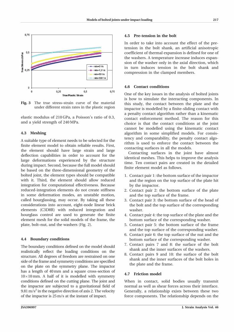
and 500.00m/m.s as shown in Fig. 3. The material
has an elastic modulus of 205GPa, a Poisson’s ratio
of 0.33, and a density of 7800 kg/m3. An isotropic
hardening model was used in the finite element
model simulations, with the size of the yielded
region changing uniformly in all directions.
The impactor is assumed to be elastically de-
formed. It has an elastic modulus of 600GPa, a
Poisson’s ratio of 0.3, and density of 30 000 kg/m3.
Additionally, the bolt and washer material has an
Fig. 1 The full model for a drop test
Fig. 2 The individual components of the symmetric half model
4 N Tanlak, FO Sonmez, and E Talay
J. Strain Analysis Vol. 46 JSA396997
Models of bolted joints under impact loading 217
elastic modulus of 210GPa, a Poisson’s ratio of 0.3,
and a yield strength of 240MPa.
4.3 Meshing
A suitable type of element needs to be selected for the
finite element model to obtain reliable results. First,
the element should have large strain and large
deflection capabilities in order to account for the
large deformations experienced by the structure
during impact. Second, because the full model should
be based on the three-dimensional geometry of the
bolted joint, the element types should be compatible
with it. Third, the element should allow reduced
integration for computational effectiveness. Because
reduced-integration elements do not create stiffness
in some deformation modes, an unstable motion,
called hourglassing, may occur. By taking all these
considerations into account, eight-node linear brick
elements (C3D8R) with reduced integration and
hourglass control are used to generate the finite
element mesh for the solid models of the frame, the
plate, bolt–nut, and the washers (Fig. 2).
4.4 Boundary conditions
The boundary conditions defined on the model should
realistically reflect the loading conditions on the
structure. All degrees of freedom are restrained on one
side of the frame and symmetry conditions are specified
on the plate on the symmetry plane. The impactor
has a length of 40mm and a square cross-section of
10610mm. A half of it is modelled with symmetry
conditions defined on the cutting plane. The joint and
the impactor are subjected to a gravitational field of
9.81m/s2 in the negative direction of axis 2. The velocity
of the impactor is 25m/s at the instant of impact.
4.5 Pre-tension in the bolt
In order to take into account the effect of the pre-
tension in the bolt shank, an artificial anisotropic
coefficient of thermal expansion is defined for one of
the washers. A temperature increase induces expan-
sion of the washer only in the axial direction, which
in turn induces tension in the bolt shank and
compression in the clamped members.
4.6 Contact conditions
One of the key issues in the analysis of bolted joints
is how to simulate the interacting components. In
this study, the contact between the plate and the
impactor is modelled by a finite-sliding contact with
a penalty contact algorithm rather than a kinematic
contact enforcement method. The reason for this
choice is that the contact conditions at the joint
cannot be modelled using the kinematic contact
algorithm in some simplified models. For consis-
tency and comparability, the penalty contact algo-
rithm is used to enforce the contact between the
contacting surfaces in all the models.
Contacting surfaces in the joint have almost
identical meshes. This helps to improve the analysis
time. Ten contact pairs are created in the detailed
finite element model as follows.
1. Contact pair 1: the bottom surface of the impactor
and the region on the top surface of the plate hit
by the impactor.
2. Contact pair 2: the bottom surface of the plate
and the top surface of the frame.
3. Contact pair 3: the bottom surface of the head of
the bolt and the top surface of the corresponding
washer.
4. Contact pair 4: the top surface of the plate and the
bottom surface of the corresponding washer.
5. Contact pair 5: the bottom surface of the frame
and the top surface of the corresponding washer.
6. Contact pair 6: the top surface of the nut and the
bottom surface of the corresponding washer.
7. Contact pairs 7 and 8: the surface of the bolt
shank and the inner surfaces of the washers.
8. Contact pairs 9 and 10: the surface of the bolt
shank and the inner surfaces of the bolt holes in
the plate and the frame.
4.7 Friction model
When in contact, solid bodies usually transmit
normal as well as shear forces across their interface.
Generally, a relationship exists between these two
force components. The relationship depends on the
Fig. 3 The true stress–strain curve of the materialunder different strain rates in the plastic region
Models of bolted joints under impact loading 5
JSA396997 J. Strain Analysis Vol. 46

N Tanlak, FO Sonmez, and E Talay218
magnitude of the contact forces as well as slip rate.
In this study, a Coulomb friction model is adopted.
Typical values are chosen for static and kinetic
friction coefficients in metal-to-metal contact, which
are 0.15 and 0.12, respectively. To create the
transition from a zero slip rate to high slip rates, an
exponentially decaying function is used for the
frictional coefficient.
4.8 Time increments
The time increment used in an explicit analysis
should be smaller than the stability limit of the
central-difference operation. Otherwise, the solution
becomes unstable and displacements may oscillate
with increasing amplitudes. The stability limit is
usually chosen as the smallest transition time of a
stress wave across any element in the mesh. In crash
problems involving large deformations, the highest
frequency of the model varies during impact, which
consequently alters the stability limit. For this
reason, a fully automatic time-increment scheme
in ABAQUS/Explicit is used in the present analyses
to account for changes in the stability limit.
5 SIMPLIFIED FINITE ELEMENT MODELS
In this study, a number of models were developed to
simulate the clamping effect of bolted joints in a
simplifying manner by accounting for only the
dominant factors. All the simplified models were
then compared with the full model regarding
accuracy and computational time. In order to reach
a meaningful comparison, almost all the parameters
and analysis options including mesh pattern and
contact enforcement methods were chosen to be the
same in all the models.
In the simplified models, shell elements are used
instead of solid elements to model the metal sheets
based on the fact that the thickness is very small in
comparison to the lateral lengths. The element type
used in the models is S4R, a four-node quadrilateral
shell element which resulted in a reduced number of
integrations and a large-strain formulation. Simp-
son’s integration rule is used with five integration
points through the thickness.
5.1 Simplified model 1: full model with shellplates
In this model, the model for the bolt–nut assembly is
the same as the detailed model; but the plate and the
frame are discretized using shell elements (Fig. 4)
considering that their thickness-to-lateral length
ratio is less than 1/10. The shells are positioned at
the mid-surface of the sheets. The same contact
pairs as in the full model are defined.
5.2 Simplified model 2: rigid shank with couplingconstraints
In this model, the bolt shaft is conceived as a smooth
cylindrical shaft discretized with solid elements
(Fig. 5). It is taken to be rigid on the basis that it is
considerably more stiff than the sheet because of its
large diameter in comparison to the sheet’s thick-
ness. The effects of the bolt head and nut are
simulated through coupling constraints. The central
nodes on the upper and lower surfaces of the
cylinder are used as control points for the coupling
constraints. The constraints are applied to the
surfaces of the sheets that are under the direct
clamping pressure of the washers. A distributing
coupling constraint is used in which all degrees of
Fig. 4 Simplified model 1: full model with shell plates
Fig. 5 Simplified model 2: rigid shank with couplingconstraints
6 N Tanlak, FO Sonmez, and E Talay
J. Strain Analysis Vol. 46 JSA396997
Models of bolted joints under impact loading 219
freedom are restrained. In this way, the relative
motion between the ends of the bolt shank and the
compressed region on the sheets is prevented. This
means that the bolt head, nut, and washers are
assumed to be non-deformable and relative motion
between the washers and the sheets is assumed not
to exist. Only the contact pairs 1, 2, 9, and 10 are
introduced in this model.
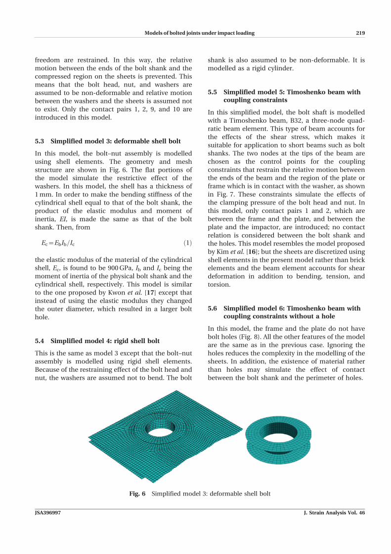
5.3 Simplified model 3: deformable shell bolt
In this model, the bolt–nut assembly is modelled
using shell elements. The geometry and mesh
structure are shown in Fig. 6. The flat portions of
the model simulate the restrictive effect of the
washers. In this model, the shell has a thickness of
1mm. In order to make the bending stiffness of the
cylindrical shell equal to that of the bolt shank, the
product of the elastic modulus and moment of
inertia, EI, is made the same as that of the bolt
shank. Then, from
Ec~EbIb=Ic ð1Þ
the elastic modulus of the material of the cylindrical
shell, Ec, is found to be 900GPa, Ib and Ic being the
moment of inertia of the physical bolt shank and the
cylindrical shell, respectively. This model is similar
to the one proposed by Kwon et al. [17] except that
instead of using the elastic modulus they changed
the outer diameter, which resulted in a larger bolt
hole.
5.4 Simplified model 4: rigid shell bolt
This is the same as model 3 except that the bolt–nut
assembly is modelled using rigid shell elements.
Because of the restraining effect of the bolt head and
nut, the washers are assumed not to bend. The bolt
shank is also assumed to be non-deformable. It is
modelled as a rigid cylinder.
5.5 Simplified model 5: Timoshenko beam withcoupling constraints
In this simplified model, the bolt shaft is modelled
with a Timoshenko beam, B32, a three-node quad-
ratic beam element. This type of beam accounts for
the effects of the shear stress, which makes it
suitable for application to short beams such as bolt
shanks. The two nodes at the tips of the beam are
chosen as the control points for the coupling
constraints that restrain the relative motion between
the ends of the beam and the region of the plate or
frame which is in contact with the washer, as shown
in Fig. 7. These constraints simulate the effects of
the clamping pressure of the bolt head and nut. In
this model, only contact pairs 1 and 2, which are
between the frame and the plate, and between the
plate and the impactor, are introduced; no contact
relation is considered between the bolt shank and
the holes. This model resembles the model proposed
by Kim et al. [16]; but the sheets are discretized using
shell elements in the present model rather than brick
elements and the beam element accounts for shear
deformation in addition to bending, tension, and
torsion.
5.6 Simplified model 6: Timoshenko beam withcoupling constraints without a hole
In this model, the frame and the plate do not have
bolt holes (Fig. 8). All the other features of the model
are the same as in the previous case. Ignoring the
holes reduces the complexity in the modelling of the
sheets. In addition, the existence of material rather
than holes may simulate the effect of contact
between the bolt shank and the perimeter of holes.
Fig. 6 Simplified model 3: deformable shell bolt
Models of bolted joints under impact loading 7
JSA396997 J. Strain Analysis Vol. 46

N Tanlak, FO Sonmez, and E Talay220
5.7 Simplified model 7: tie constraint with hole
In this model, force transfer between the frame and
the plate is achieved through a tie constraint defined
between the inner surfaces of the sheets in the
region compressed by the washers (Fig. 9). Tie
constraints can be used to make the translational
and rotational motions in all degrees of freedom the
same for two surfaces.
5.8 Simplified model 8: tie constraint withou ahole
This model also uses a tie constraint in order to
model the clamping effect of the bolt–nut assembly
as in the previous case; but there is no hole in this
case. The relative distance between the plate and the
frame in this region is thus kept constant during the
impact via this constraint.
5.9 Simplified model 9: cross-coupling constraint
In this model, a kinematic coupling constraint is
used to simulate the force transmission between the
sheets (Fig. 10). A control point is defined at the
centre of the bolt hole. All degrees of freedom at the
nodes on the surfaces compressed by the washers
are coupled with those of the control point. Only
contact pairs 1 and 2 are introduced in this model.
5.10 Simplified model 10: connector beams alongthe perimeter of the hole
In this model, as can be seen in Fig. 11, 12 connector
beam-type elements are defined, each element being
Fig. 8 Simplified model 6: Timoshenko beam withcoupling constraints without a hole
Fig. 9 Simplified model 7: tie constraint with hole
Fig. 10 Simplified model 9: cross-coupling constraint
Fig. 7 Simplified model 5: Timoshenko beam withcoupling constraints
Fig. 11 Simplified model 10: connector beams alongthe perimeter of the hole
8 N Tanlak, FO Sonmez, and E Talay
J. Strain Analysis Vol. 46 JSA396997

Models of bolted joints under impact loading 221
between the corresponding nodes of the plate and the
frame to create a rigid connection between the two
sheets. They are positioned on the perimeters of the
bolt holes. Assuming the bolt–nut assembly to be
non-deformable, relative motion between the sheets
may be assumed to be completely prevented through
the clamping pressure of the bolted joint. Accord-
ingly, rigid connectors prevent relative motion be-
tween the plate and the frame at the perimeters.
5.11 Simplified model 11: connector beams alongthe perimeter of the hole and the washer’souter profile
The only difference between this model and the
previous one is the additional restrained circular
region. Twelve more connector beam elements are
used to connect the frame and the plate along the
projection of the outer edge of the washers (Fig. 12).
In this way relative motion is prevented at extra
points in the compressed region.
5.12 Simplified model 12: cross connector beams
In this model, there are 12 connector beam-type
elements that join themidpoint of the line between the
centres of the holes and nodes at the perimeters. Six of
the connector elements are connected to the plate and
the other six are connected to the frame (Fig. 13). Only
the contact pairs 1 and 2 are introduced in this model.
6 RESULTS AND DISCUSSION
6.1 Validation of the solution
Because the finite element method is an approx-
imate solution technique, one should ensure that the
resulting error is less than an acceptable limit. The
finite element software guides the user by issuing
some warning messages for certain mistakes that the
user can make in the modelling; but one should not
solely rely on these messages. One of the ways to
check the accuracy of the results is to use mesh-
convergence analysis. One should determine the
range of values for the mesh size for which one can
obtain consistent results. Energy output is another
indicator for the validity of the results of an explicit
analysis. Based on comparisons between various
energy components one may decide whether an
analysis has yielded acceptable results.
6.1.1 Examination of the energy outputs
The energy balance for the entire system can be
written as
EIzEK{ EW{EFD{EVDð Þ~constant ð2Þ
where EI is the internal energy, EK is the kinetic
energy, EW is the work done on the structure by the
externally applied loads, EFD is the frictional energy
dissipated, and EVD is the viscous energy dissipated.
The internal energy, EI, is the sum of the recoverable
elastic strain energy, EE, the energy dissipated
through inelastic processes such as plasticity, EP,
the energy dissipated through viscoelasticity or
creep, ECD, and the artificial strain energy, EA
EI~EEzEPzECDzEA ð3Þ
The artificial strain energy is introduced into the
numerical model to constrain the hourglass defor-
mation modes; therefore it is not associated with real
deformation modes. Large values of the artificial
energy mean that a significant portion of the impact
Fig. 12 Simplified model 11: connector beams alongthe perimeter of the hole and the washer’souter profile
Fig. 13 Simplified model 12: cross connector beams
Models of bolted joints under impact loading 9
JSA396997 J. Strain Analysis Vol. 46
N Tanlak, FO Sonmez, and E Talay222
energy is used to stabilize the computational process
rather than to simulate the physical process. In that
case, improvement in the mesh is required. As an
additional requirement the resultant sum of these
energy components, given in equation (2) for the
entire system, should remain constant.
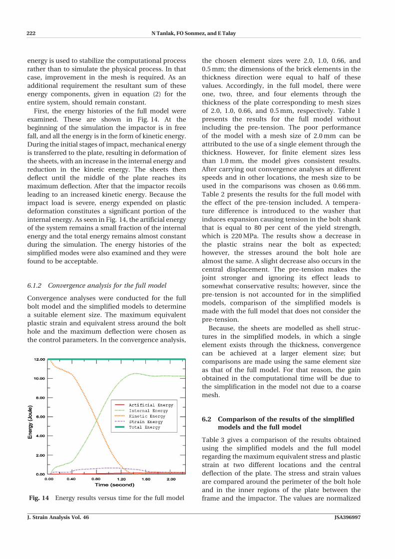
First, the energy histories of the full model were
examined. These are shown in Fig. 14. At the
beginning of the simulation the impactor is in free
fall, and all the energy is in the form of kinetic energy.
During the initial stages of impact, mechanical energy
is transferred to the plate, resulting in deformation of
the sheets, with an increase in the internal energy and
reduction in the kinetic energy. The sheets then
deflect until the middle of the plate reaches its
maximum deflection. After that the impactor recoils
leading to an increased kinetic energy. Because the
impact load is severe, energy expended on plastic
deformation constitutes a significant portion of the
internal energy. As seen in Fig. 14, the artificial energy
of the system remains a small fraction of the internal
energy and the total energy remains almost constant
during the simulation. The energy histories of the
simplified modes were also examined and they were
found to be acceptable.
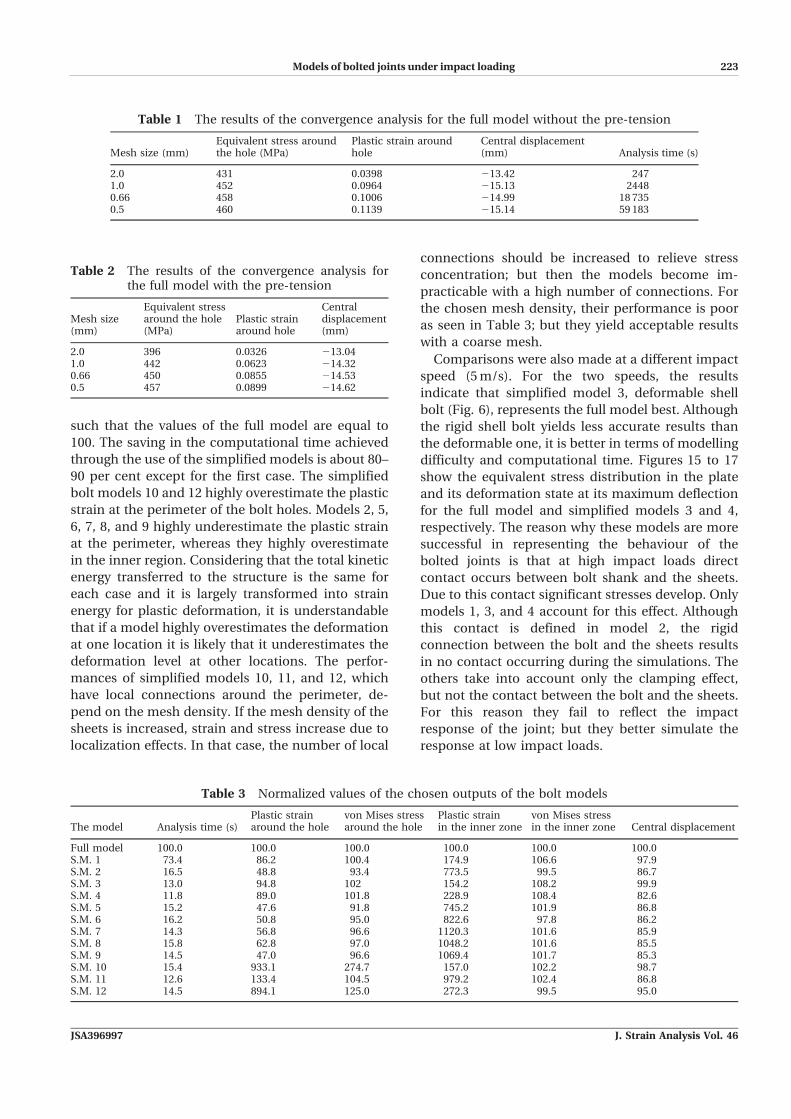
6.1.2 Convergence analysis for the full model
Convergence analyses were conducted for the full
bolt model and the simplified models to determine
a suitable element size. The maximum equivalent
plastic strain and equivalent stress around the bolt
hole and the maximum deflection were chosen as
the control parameters. In the convergence analysis,
the chosen element sizes were 2.0, 1.0, 0.66, and
0.5mm; the dimensions of the brick elements in the
thickness direction were equal to half of these
values. Accordingly, in the full model, there were
one, two, three, and four elements through the
thickness of the plate corresponding to mesh sizes
of 2.0, 1.0, 0.66, and 0.5mm, respectively. Table 1
presents the results for the full model without
including the pre-tension. The poor performance
of the model with a mesh size of 2.0mm can be
attributed to the use of a single element through the
thickness. However, for finite element sizes less
than 1.0mm, the model gives consistent results.
After carrying out convergence analyses at different
speeds and in other locations, the mesh size to be
used in the comparisons was chosen as 0.66mm.
Table 2 presents the results for the full model with
the effect of the pre-tension included. A tempera-
ture difference is introduced to the washer that
induces expansion causing tension in the bolt shank
that is equal to 80 per cent of the yield strength,
which is 220MPa. The results show a decrease in
the plastic strains near the bolt as expected;
however, the stresses around the bolt hole are
almost the same. A slight decrease also occurs in the
central displacement. The pre-tension makes the
joint stronger and ignoring its effect leads to
somewhat conservative results; however, since the
pre-tension is not accounted for in the simplified
models, comparison of the simplified models is
made with the full model that does not consider the
pre-tension.
Because, the sheets are modelled as shell struc-
tures in the simplified models, in which a single
element exists through the thickness, convergence
can be achieved at a larger element size; but
comparisons are made using the same element size
as that of the full model. For that reason, the gain
obtained in the computational time will be due to
the simplification in the model not due to a coarse
mesh.
6.2 Comparison of the results of the simplifiedmodels and the full model
Table 3 gives a comparison of the results obtained
using the simplified models and the full model
regarding the maximum equivalent stress and plastic
strain at two different locations and the central
deflection of the plate. The stress and strain values
are compared around the perimeter of the bolt hole
and in the inner regions of the plate between the
frame and the impactor. The values are normalizedFig. 14 Energy results versus time for the full model
10 N Tanlak, FO Sonmez, and E Talay
J. Strain Analysis Vol. 46 JSA396997
Models of bolted joints under impact loading 223
such that the values of the full model are equal to
100. The saving in the computational time achieved
through the use of the simplified models is about 80–
90 per cent except for the first case. The simplified
bolt models 10 and 12 highly overestimate the plastic
strain at the perimeter of the bolt holes. Models 2, 5,
6, 7, 8, and 9 highly underestimate the plastic strain
at the perimeter, whereas they highly overestimate
in the inner region. Considering that the total kinetic
energy transferred to the structure is the same for
each case and it is largely transformed into strain
energy for plastic deformation, it is understandable
that if a model highly overestimates the deformation
at one location it is likely that it underestimates the
deformation level at other locations. The perfor-
mances of simplified models 10, 11, and 12, which
have local connections around the perimeter, de-
pend on the mesh density. If the mesh density of the
sheets is increased, strain and stress increase due to
localization effects. In that case, the number of local
connections should be increased to relieve stress
concentration; but then the models become im-
practicable with a high number of connections. For
the chosen mesh density, their performance is poor
as seen in Table 3; but they yield acceptable results
with a coarse mesh.
Comparisons were also made at a different impact
speed (5m/s). For the two speeds, the results
indicate that simplified model 3, deformable shell
bolt (Fig. 6), represents the full model best. Although
the rigid shell bolt yields less accurate results than
the deformable one, it is better in terms of modelling
difficulty and computational time. Figures 15 to 17
show the equivalent stress distribution in the plate
and its deformation state at its maximum deflection
for the full model and simplified models 3 and 4,
respectively. The reason why these models are more
successful in representing the behaviour of the
bolted joints is that at high impact loads direct
contact occurs between bolt shank and the sheets.
Due to this contact significant stresses develop. Only
models 1, 3, and 4 account for this effect. Although
this contact is defined in model 2, the rigid
connection between the bolt and the sheets results
in no contact occurring during the simulations. The
others take into account only the clamping effect,
but not the contact between the bolt and the sheets.
For this reason they fail to reflect the impact
response of the joint; but they better simulate the
response at low impact loads.
Table 1 The results of the convergence analysis for the full model without the pre-tension
Mesh size (mm)Equivalent stress aroundthe hole (MPa)
Plastic strain aroundhole
Central displacement(mm) Analysis time (s)
2.0 431 0.0398 213.42 2471.0 452 0.0964 215.13 24480.66 458 0.1006 214.99 18 7350.5 460 0.1139 215.14 59 183
Table 2 The results of the convergence analysis forthe full model with the pre-tension
Mesh size(mm)
Equivalent stressaround the hole(MPa)
Plastic strainaround hole
Centraldisplacement(mm)
2.0 396 0.0326 213.041.0 442 0.0623 214.320.66 450 0.0855 214.530.5 457 0.0899 214.62
Table 3 Normalized values of the chosen outputs of the bolt models
The model Analysis time (s)Plastic strainaround the hole
von Mises stressaround the hole
Plastic strainin the inner zone
von Mises stressin the inner zone Central displacement
Full model 100.0 100.0 100.0 100.0 100.0 100.0S.M. 1 73.4 86.2 100.4 174.9 106.6 97.9S.M. 2 16.5 48.8 93.4 773.5 99.5 86.7S.M. 3 13.0 94.8 102 154.2 108.2 99.9S.M. 4 11.8 89.0 101.8 228.9 108.4 82.6S.M. 5 15.2 47.6 91.8 745.2 101.9 86.8S.M. 6 16.2 50.8 95.0 822.6 97.8 86.2S.M. 7 14.3 56.8 96.6 1120.3 101.6 85.9S.M. 8 15.8 62.8 97.0 1048.2 101.6 85.5S.M. 9 14.5 47.0 96.6 1069.4 101.7 85.3S.M. 10 15.4 933.1 274.7 157.0 102.2 98.7S.M. 11 12.6 133.4 104.5 979.2 102.4 86.8S.M. 12 14.5 894.1 125.0 272.3 99.5 95.0
Models of bolted joints under impact loading 11
JSA396997 J. Strain Analysis Vol. 46

N Tanlak, FO Sonmez, and E Talay224
7 CONCLUSIONS
Development of accurate and computationally effi-
cient finite element models of bolted joints under
impact loading was the goal of this study. In order to
accurately determine the response of the structure, a
detailed model was developed that accounted for
almost all of the factors that influenced the stress
and strain states in the joined sheets. In order to
determine the structural response at a minimal
computational burden, a number of simplified
models were developed. The full model was then
used as a benchmark for the accuracy of the
simplified models.
All of the simplified models, except simplified
model 1, saved significant computational time when
compared with the full model using the same mesh
density. The saving in the computational time is
about 80–90 per cent. Because the sheets are
discretized with solid elements in the full model,
many elements should be used through the thick-
ness to obtain convergence, unlike the simplified
models in which shell elements are used. For this
reason, convergence of the simplified models can be
obtained with coarser meshes. In view of that, actual
savings in time are much larger in practice.
Among the simplified models, model 3 most
accurately predicts the mechanical behaviour of
the structure for different loading cases and mesh
densities. Complexity of the geometry is also greatly
reduced in the model.
ACKNOWLEDGEMENT
Platform R&D and TOFAS Turk Otomobil Fabrikasiare gratefully acknowledged for their support of thisresearch.
F Authors 2011
REFERENCES
1 Mistakidis, E. S. and Baniotopoulos, C. C. Steel T-stub connections under static loading: an effective
Fig. 15 Deformation state and equivalent stress stateof the plate at the maximum deflection for thefull model
Fig. 16 Deformation state and equivalent stress stateof the plate at the maximum deflection forsimplified model 3
Fig. 17 Deformation state and equivalent stress stateof the plate at the maximum deflection forsimplified model 4
12 N Tanlak, FO Sonmez, and E Talay
J. Strain Analysis Vol. 46 JSA396997

Models of bolted joints under impact loading 225
2-D numerical model. J. Construct. Steel Res., 1997,44, 51–67.
2 Bursi, O. S. and Jaspart, J. P. Benchmarks formodelling of bolted connections. J. Construct. SteelRes., 1997, 43, 17–42.
3 Bursi, O. S. and Jaspart, J. P. Calibration of a finiteelement model for isolated bolted end-plate steelconnections. J. Construct. Steel Res., 1997, 44,225–262.
4 Bursi, O. S. and Jaspart, J. P. Basic issues in thefinite element simulation of extended end plateconnections. Comput. Struct., 1998, 69, 361–382.
5 Chung, K. F. and Ip, K. H. Finite elementmodelling of bolted connections between coldformed steel strips and hot rolled steel platesunder static shear loading. Engng Struct., 2000,22, 1271–1284.
6 Chung, K. F. and Ip, K. H. Finite elementinvestigation on the structural behaviour of cold-formed steel bolted connections. Engng Struct.,2001, 23, 1115–1125.
7 Kishi, N., Ahmed, A., and Yabuki, N. Nonlinearfinite element analysis of top- and seat- angle withdouble web angle connections. Struct. EngngMech., 2001, 12, 201–214.
8 Swanson, J. A., Kokan, D. S., and Leon, R. T.Advanced finite element modelling of bolted T-stub connection components. J. Construct. SteelRes., 2002, 58, 1015–1031.
9 Barth, K. E., Orbison, J. G., and Nukala, R.Behaviour of steel tension members subjected touniaxial loading. J. Construct. Steel Res., 2002, 58,1103–1120.
10 Citipitioglu, A. M., Haj-Ali, R. M., andWhite, D. W.Refined 3D finite element modelling of partially-restrained connections including slip. J. Construct.Steel Res., 2002, 58, 995–1013.
11 Ju, S. H., Fan, C. Y., and Wu, G. H. Three-dimensional finite elements of steel bolted con-nections. Engng Struct., 2004, 26, 403–413.
12 Yorgun, C., Dalci, S., and Altay, G. A. Finiteelement modelling of bolted steel connections
designed by double channel. Comput. Struct.,2004, 82, 2563–2571.
13 Webber, J. P. H., Graham, U., and Wisnom, M. R.Strain distributions around fasteners in laminatedplates under biaxial in-plane loading. J. Strain Anal.Engng Des., 1997, 32(3), 167–174.
14 Butterworth, J. Finite element analysis of struc-tural steelwork beam to column bolted connec-tions, Report, University of Teesside, UK, 2003.
15 McCarthy, M. A., McCarthy, C. T., Lawlor, V. P.,and Stanley, W. F. Three-dimensional finite ele-ment analysis of single-bolt, single-lap compositebolted joints: part I - model development andvalidation. Compos. Struct., 2005, 71, 140–158.
16 Kim, J., Yoon, J. C., and Kang, B. S. Finite elementanalysis and modelling of structure with boltedjoints. Appl. Math. Model., 2007, 31, 895–911.
17 Kwon, Y. D., Kwon, H. W., Hwangbo, J. H., andJang, S. H. Finite element modelling for static anddynamic analysis of structures with bolted joint.Key Engng Mater., 2006, 306–308, 547–552.
18 Sabuwala, T., Linzell, D., and Krauthammer, T.Finite element analysis of steel beam to columnconnections subjected to blast loads. Int. J. ImpactEngng, 2005, 31, 861–876.
19 Reid, J. D. and Hiser, N. R. Detailed modelling ofbolted joints with slippage. Finite Elem. Anal. Des.,2005, 41, 547–562.
20 Oldfield, M., Ouyang, H., and Mottershead, J. E.Simplified models of bolted joints under harmonicloading. Comput. Struct., 2005, 84, 25–33.
21 Hendricks, B. F. and Wekezer, J. W. Finite elementmodelling of G2 guardrail. Transp. Res. Record,1996, 1528, 130–137.
22 O’Daniel, J. L., Koudela, K. L., and Krauthammer,T. Numerical simulation and validation of distrib-uted impact events. Int. J. Impact Engng, 2005, 31,1013–1038.
23 Harewood, F. J. and McHugh, P. E. Comparison ofthe implicit and explicit finite element methodsusing crystal plasticity. Comput. Mater. Sci., 2007,39, 481–494.
Models of bolted joints under impact loading 13
JSA396997 J. Strain Analysis Vol. 46


![Bolted Connections[1]](https://img.pdfslide.us/doc/110x75/54e7f8c84a7959704f8b46b8/bolted-connections1.jpg)