Embed Size (px)
Citation preview

1
Lesson 5
schnabel-eng.com
Design of Micropiles for Structural Foundations
Learning Outcomes
Evaluate structural and geotechnical capacity of micropiles and micropile groupsIdentify special design considerations for micropilesmicropiles
Micropile Structural Design Basics
Fundamentals are similar to traditional pile designDue to the small structural section, structural design and stiffness can often control (asdesign and stiffness can often control (as compared to geotechnical failure)

2
Typical Micropile Detail
TOP OF FOOTINGCL
MICROPILEREINFORCING BAR
BOTTOM OF FOOTINGCASED UPPER
MICROPILE
PILE CAP ANCHORAGE
STEEL CASING
GROUT
CENTRALIZER
CASING PLUNGELENGTH
PRESSUREGROUTED
MICROPILEBOND LENGTH
LENGTH
TOP OF DENSESOIL / ROCK
GROUTED BOND ZONEDIAMETER (DIA BOND)
Design Process
Step 1 Evaluate Feasibility of Micropiles
Step 2 Review Project Information
St 3 E t bli h L d d P fStep 3 Establish Load and Performance Requirements
Step 4 Preliminary Design Considerations
Step 5 Evaluate Structural Capacity of Cased Length
Design Process
Step 6 Evaluate Structural Capacity of Uncased Length
Step 7 Compare Capacity to Need
Step 8 Evaluate Geotechnical Capacity of Micropile
Step 9 Estimate Micropile Movements
Step 10 Design Micropile/Footing Connection
Step 11 Develop Load Testing Program
Step 12 Drawings and Specifications

3
Step 1. Evaluate Feasibility
Subsurface conditionsDifficult access or limited overhead clearance Subsurface voidsVibration limitsVibration limitsUnderpinning or retrofitting of existing foundations
Step 2. Review Project Information
Geologic conditionsSite historyGeotechnical dataEnvironmental conditionsEnvironmental conditions
Review of Geotechnical Data
Review published informationObtain samples Develop profilesEstimate design parametersEstimate design parametersEvaluate corrosion potentialIdentify problem areasLiquefaction

4
How Many Borings Do I Need ?
Application Min. No. Exploration Points
Minimum Depth
Deep Foundations Structure Size <100 ft, one point at each structure
Soils: at least 20 ft below anticipated deep foundation tip grade not less than
>100 ft, min 2 points at each structure
2x the maximum group dimension
Rock: minimum 10 ft, but below the anticipated tip or 2x group dimension
After FHWA-IF-02-034
Step 3. Establish Applicable Loading Cases
Battered micropiles required for large lateral loading applications For retrofits, need to consider existing foundation loads and whether these loads willfoundation loads and whether these loads will be carried solely or shared by micropilesMicropile geotechnical capacity will be confirmed via load testing to 2.0 times the design loadingEstablish deflection criteria
Load Cases
AASHTO Bridge Design Specification load cases will combine items such as:
Live DeadWindSeismicDowndragScour…

5
Step 4. Preliminary Design Considerations
Micropile spacingMicropile lengthMicropile cross sectionMicropile typeMicropile type
Micropile Spacing
At least 3 micropile diameters or 760 mmDepends on condition of existing footing, access to footing, and magnitude of loads
Micropile Length
Depth to good groundDepth to establish fixity for lateral loading applicationDepth to resist downdrag loads D th f i ifi tDepth of significant scourImpact of group loads on a compressible layerLocation of liquefiable layers, karstic features, and other underground anomalies

6
Micropile Cross Section
Typically selected based on rough estimate of required diameter to resist axial design loadsUse common casing sizes (refers to outside diameter)diameter)
5-1/2 in <100 Ton7 in. 100-150 Ton9-5/8 in >150 Ton
Nominal yield stress of 80 ksi
Design Engineers Must Understand Available Tools
Drilling rigsDrilling methodsAvailable structural materialsReasonable bond valuesQuality control
Structural Design –Compression/Tension Only
Grout & steel {{Transfer zone
(plunge)
Bond zone
{
{

7
Step 5. Structural Design of Cased Length - Compression
P ll bl i l d
(Eq. 5-1 )
Pc-allowable= [ 0.4 f’c grout x Agrout + 0.47Fy-steel (Abar+Acasing)]
Pc-allowable = allowable compression load; f’c grout = unconfined compressive strength of grout
(typically a 28-day strength);Agrout = area of grout in micropile cross section;Fy-steel = yield stress of steel;Abar = cross sectional area of steel reinforcement bar (if
used);Acasing = cross sectional area of steel casing (adjusted for
assumed steel section losses due to corrosion).
Step 5. Structural Design of Cased Length - Tension
(Eq. 5-2 )
Pt-allowable= [0.55Fy-steel (Abar+Acasing)]
Do not consider grout in this calculationAssume zero (or small) tension load carried by casing if threaded joints on casing and no lab data available
( q )
Step 6. Structural Design of Uncased Length
Compression
(Eq 5 7 )
Pc-allowable= [ 0.4 f’c grout x Agrout + 0.47Fy-steel xAbar ]
Tension(Eq. 5-7 )
(Eq. 5-8 )
Pt-allowable= [0.55Fy-steel (Aba+Acasing)]

8
Step 11: Load Test Structural Capacity
Check whether micropile design will be overstressed during load testingUpgrade design section, if necessary, to allow safe load testingAll bl t f 80 t f lti t iAllowable stress of 80 percent of ultimate is typical
Step 7: Compare Design Loads
Micropile Capacity > Required Design
If not, Back to Step 4
Step 8. Geotechnical Capacity of Micropile
Consider load transfer parametersGrout to ground average bond valuesIdentify variations throughout profile and across the siteDefine the required minimum bond lengthDefine testing required to confirm this
Evaluate pile spacing Impact from group effects

9
Allowable Geotechnical Bond Capacity
(E 5 9 )
αbond = grout to ground ultimate bond strengthFS = factor of safety applied to the ultimate
bond strengthDb = diameter of the drill holeLb = bond length
(Eq. 5-9 )
Grout-to-Ground Bond Values
SEE TABLE 5-3 IN MANUAL
Page
5-21
Hollow Bar Bond Values
Soil TypeMobilized Bond
Strength in Proof Tests
Bond Strength Suggested By
FHWA Type B Micropile
Sand (some silt) (fine, loose-medium
dense
27-53 psi(186.2-365.4 kPa)
10-28 psi(68.9-193.1 kPa)
Silt & Clay( d) ( tiff d t 7-28 psi 10-28 psi(some sand) (stiff, dense to very
dense)
p(50.6-193.1 kPa)
p(68.9-193.1 kPa)
Combined Soil(approximately ½ bond length in
stiff clay and ½ in medium density sand)
11-35 psi (72.4-241.3 kPa) NA

10
Factor of Safety on Bond
With load testing requirements provided (Chapter 7 of Manual), use FS = 2.0Use FS = 2.5 if,
Bond length in soil susceptible to creepBond length in soil susceptible to creepOther marginal groundPrevious experience in similar ground is limited
Geotechnical Design – Empirical
Average Bond Values (allowable loads)Clay: 1-2 k/ftLoose sands: 2-4 k/ftCompact sand: 5 10 k/ftCompact sand: 5-10 k/ftRock: 5-20+ k/ft
Typical for approximately 5 ½ to 7 inch diameter micropile
Calculate Bond Length
Rearrange Eq. 5-9 and set PG-
allowable equal to design load

11
Micropile Group Capacity
Pressure grouting results in increase in confining pressure in the ground (like driven piles)Gravity grouted micropiles result in stressGravity grouted micropiles result in stress relief in the ground (like drilled shafts)Gravity grouted micropiles, however, are only used in rocks where group effects are perceived to be negligible
Group Effects
If in cohesionless soils, assume no group effects
(where minimum spacing is satisfied)
Group Effects
For cohesive soils:Consider contact condition of cap and shear strength of soil and adjust efficiency between 0.65 and 1.0For close spacing (less than 3 micropile diameters between micropiles), consider block failure and compare to the sum of individual pile capacities

12
Step 9. Estimate Micropile Movements
Individual micropile vertical movementMicropile group settlementLateral movement
Micropile Axial Deflection
Elastic shorteningResidual movement -0.6
-0.3
0.0
n)
Δr
ΔmovementCreep movement
-1.5
-1.2
-0.9
0 100 200 300 400
Load (ton)
Settl
emen
t (in
ΔeΔt
Elastic Movement
Vertical movements (at design load) must be less than tolerable for the structureSince micropiles have small cross sections, they may have relatively significant elasticthey may have relatively significant elastic movementsLength (for elastic estimate) is not the total length installed

13
Elastic Shortening Estimate
Δelastic = PL / AE
• For micropiles in competent soil, L = length above bond length plus ½ b d l th
P
Lbond length
• For micropiles in rock, L = full length of micropile above bond length
• Axial stiffness, AE, considers steel and concrete if compression loading and steel only if tension loading
L
AE ?
Evaluate for each section of pileEgrout = 1500 ksiEsteel = 29000 ksi
Creep Movements
Creep movements concern for clayey soils with LL > 50 and PI > 20Where bond length to be established in potentially creep-sensitive ground, considerpotentially creep sensitive ground, consider preproduction load test program and verify creep movements via extended load testing

14
Group SettlementUniform Soil
Group Settlement Underlying Soft Soil
SOFT ORWEAK LAYER
LAYER WHEREBOND ZONE ISFORMED
SOFT ORWEAK LAYER
LAYER WHEREBOND ZONE ISFORMED
Step 10. Design Footing Connection Details
Shear transfer from groutBearing plateShear rings STEEL CASING
EXISTINGFOOTING
NON-SHRINKGROUT
Shear rings
EXISTING FOOTING
EXTENDED FOOTINGREINFORCING
BAR W/NUT
BEARING PLATEAS REQUIRED
STIFFNERPLATE (TYP)
BOTTOM OFFOOTING ELEV. STEEL CASING
TYP
TYP STEEL CASING
STEEL SHEAR RING (TYP)
NON – SHRINK GROUT
CHIPPED GROOVE
BOTTOM OFFOOTING ELEV.
OVERSIZED CORE HOLE(DIAMETER AS PERCONTRACT PLANS)
BOTTOM OFFOOTING ELEV.
15
Connection Examples
Step 11: Develop Load Testing Program
Chapter 7
BasisFactor of SafetyFactor of SafetyStructural Capacity of PileSchedule
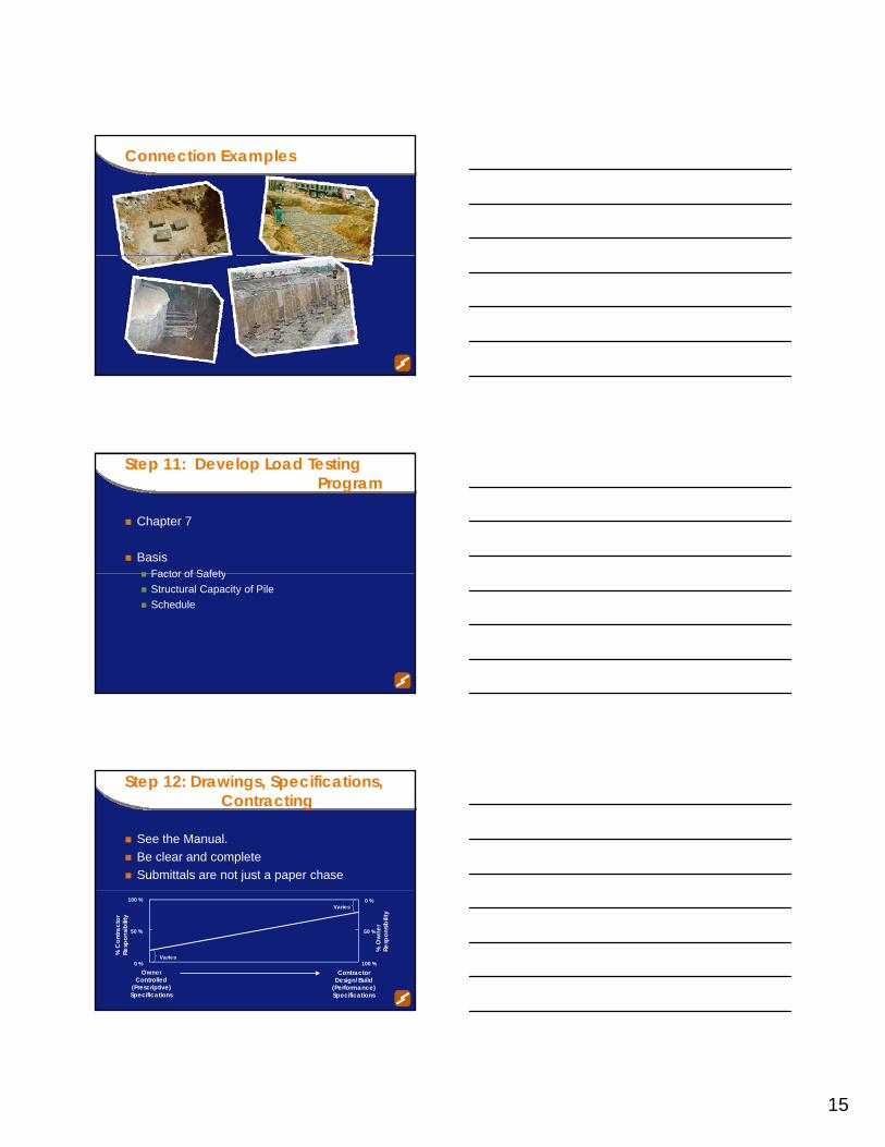
Step 12: Drawings, Specifications, Contracting
See the Manual. Be clear and completeSubmittals are not just a paper chase
0 %
100 % 0 %
100 %
% C
ontra
ctor
Re
spon
sibilit
y
Owner Controlled
(Prescriptive) Specifications
Contractor Design/Build
(Performance) Specifications
50 %
% O
wne
r Re
spon
sibilit
y
50 %
Varies
Varies

16
Sample Contract Plans
Sample Contract Plans
Other Design Considerations
Corrosion ProtectionPlunge LengthLateral LoadsBucklingBucklingSeismic

17
Corrosion Protection
The degree and extent of corrosion protection is a function of
loading conditionexpected service life of the micropilep paggressiveness of the groundperceived importance of the structureconsequences of failure
Corrosion Potential Evaluation
Test UnitsStrong Corrosion
Potential -Aggressive
AASHTO Test
Method
pH – <5, >10 T 289-91
Resistivity ohm-cm <3,000 T 288-91
Sulfates ppm >200 T 290-91
Chlorides ppm >100 T 291-91
If one or more criteria is met, assume strong corrosion potential
Corrosion ProtectionCorrosion Protection
Loading Tension1 Compression
Ground Aggressive2 Non aggressive Aggressive2 Non-aggressive
Casing a. Do not rely on casing for load capacity
a. None required if tension load on casing is less than 20% of casing thread strength
OR
a. Min.1.6 mm (0.063 in.) corrosion loss on outside
The Specifier may use different corrosion loss per site-specific
a. NoneThe Specifier may
use different corrosion loss per site-specific corrosionSEE TABLE 5 6 IN MANUALOR
a. Do not rely on casing for load capacity
loss per site-specific corrosion studies.
corrosion studies.
Core steel(reinforcing bar)l
a. epoxy coating3
ORa. galvanization3
ORa. encapsulation
in plasticsheath3
ANDGrout cover4
a. bare steel5ORa. epoxy coating3
ORa. galvanization3
ORa. encapsulation in
plastic sheath3
ANDGrout cover4
a. Grout cover4
ANDThe Specifier may desire
to add other optionslisted for tension.
a. Grout cover4
SEE TABLE 5-6 IN MANUAL
Page 5-50

18
Casing Plunge Length - Ptransfer
WORKSHOP PROBLEM 1
Problem Statement
Deep foundations are required to support column loads for bridge.Micropiles have been selected for the project: (1) a 320-kip design load micropile; and (2) a(1) a 320 kip design load micropile; and (2) a 200-kip design load micropile

19
Subsurface Conditions
Site is underlain by approximately 20 ft of undocumented and variable fill overlying partially weathered rock. The soil matrix of the fill is characterized as loose to very dense silty to clayey sand.The groundwater table is located 15 ft below the current ground surface.Approximately 10 ft of new fill will be placed over the existing fill to establish foundation grades.
Soil/Rock DataRQD values for the bedrock greater than 85 percentMinimum unconfined compressive strength of rock is 5 ksi
200 Kip Micropile Detail 320 Kip Micropile Detail

20
Required
Evaluate the Contractor-provided designStructural capacity of uncased length (also referred to as socketed length)Structural capacity of cased lengthAdequacy of proposed bond length
Manual References
Structural Capacity of Uncased LengthSection 5.7 of Manual (page 5-17, Eq. 5-7)
Structural Capacity of Cased LengthSection 5 6 of Manual (page 5-10 Eq 5-1)Section 5.6 of Manual (page 5 10, Eq. 5 1)
Adequacy of Bond LengthSection 5.9.2 of Manual (page 5-19, Eq. 5-10 and Page 5-21, Table 5-3)
200 Kip Micropile Material Parameters
Portion of Micropile Property Value Casing Outside Diameter 5.5 in. Casing Wall Thickness 0.415 in. Casing Yield Strength 80 ksi
Cased Length Compressive Strength of Grout 4 ksi
R i f i B Di t 2 5 iReinforcing Bar Diameter 2.5 in.Reinforcing Bar Yield Strength 150 ksi
Socketed Length
Compressive Strength of Grout 4 ksi

21
320 Kip Micropile Material Parameters
Portion of Micropile Property Value Casing Outside Diameter 7.75 in. Casing Wall Thickness 0.595 in. Casing Yield Strength 80 ksi
Cased Length Compressive Strength of Grout 4 ksi
Reinforcing Bar Diameter 2.5 in. / 1.75 in. gReinforcing Bar Yield Strength 150 ksi / 150 ksi Socketed Length Compressive Strength of Grout 4 ksi
Lesson 5, Part II
schnabel-eng.com
Design of Micropiles for Structural Foundations
Lateral Loads on Micropiles
What controls lateral strength of a pile?What controls lateral strength of a pile?
And what’s special about a micropile?

22
Lateral Stability Under Combined Loads
Lateral deflection
PP-Δ Effect:
ΔAdditional deflection
Eccentricity
Additional bending
Do We Have Time?
For Lateral Loading and Buckling…
LPILE
Use for single micropilesNonlinear soil response modeled through p-y curvesLinear or nonlinear pile responseDefine free head, fixed head, or rotation magnitudeMultiple load combinations and boundary conditionsGroup effects not considered. Need to do manually

23
FB-Pier and GROUP
Best for pile group analysisNonlinear soil response modeled through p-y curves and response curves for axial load transfer (side and end bearing)transfer (side and end bearing)Linear or nonlinear pile responseDefine rotational stiffness of superstructureMay introduce batterVery powerful
P-y Curves
σ
P = σ x B
B = pile diam.
σ
P-y Curves
1
2
4
Es (lb/in2)
3
Pult
2
3
4
y (in)
3
2
1

24
Example
0
50
-0.5 0 0.5 1 1.5 2 2.5 3
Deflection (in)
Medium Sand
100
150
200
250
Dep
th (i
n)
1 kip2 kip5 kip10 kip20 kip
Micropile:
7-inch casing
t= 0.5 inch
Fy = 80 ksi
Free Head
Example
0
50
-0.5 0 0.5 1 1.5 2 2.5 3
Deflection (in)
First 5-10 ft critical
Acceptable deflection under 10 kip (~3/4 inch)
100
150
200
250
Dep
th (i
n)
1 kip2 kip5 kip10 kip20 kip
20 kip is close to ultimate
For fixed head, deflection <1 inch under 20 kip
Example – 10 kip Case
Max Moment ~ 400 in-kip at ~5ft
Section Modulus of Casing S = 15.5 in3
0204060
-200 0 200 400Moment (in-lb)Moment (in-kip)
Maximum Bending Stress = 400 in-kip / 15.5 = 26 ksi (0.32 Fy) OK
Usually, deflection controls for free head condition. Moment often controls for fixed head condition
6080100120140160180200
Dep
th (i
n)

25
Combined Axial Compression and Bending Stress
(Eq. 5-3 )
fa = axial stress (assumes all load carried by steel)fb = bending stress (=Mmax/S)Fa = allowable axial stress in steel (0.47 Fy)Fb = allowable bending stress (0.55 Fy)F’e = Euler buckling stress (a function of unbraced length)
( q )
(Eq. 5-6 )
Combined Axial Compression and Bending Stress – Alternate Evaluation
• Pc = maximum axial compression load• Pc-allowable = allowable compression load (Eq. 5-1)• Mmax = maximum bending moment• Mallowable = (0.55 × Fy ×S)
( q )
Lateral Loading Analysis -Summary
Good subsurface data near surface is critical p-y curves in computer programs developed for larger diameter drilled shafts so it is conservativeconservativeUse appropriate level of fixity to model ground line boundary conditionUse available lateral load test data

26
Threaded Casing Connections
Structural Capacity at Threaded Connection
For compression only, capacity is not affected by threaded connectionsFor tension/bending, no codified testing procedure is available to evaluate strength atprocedure is available to evaluate strength at connectionQualified Engineer to evaluate supplier-provided dataConservative method provided herein\
Analysis of Threaded Connection for Bending
Assume casing wall thickness, tw, is equal to ½ of the thickness of the intact casingCalculate casing area and section modulus based on this reduced thicknessbased on this reduced thickness
Casing with tw
Casing thread with tw/2

27
Four Point Bending Test Data(at Threaded Joints)
Casing Maximum Moment(Kip-in)
7” – ½” wall (N80) 1120
7” – ½” wall (N80) 1200
9 5/8” – ½” wall w/ 7”- ½” wall inside (N80)
3000
Example
0
5
10
-100 0 100 200 300 400 500Bending Moment (in-kip)
Medium Sand
10 kips
320 kips
10
15
20
25
30
35
40
Dep
th (f
t)
Medium Sand
Micropile:
7.75-inch casing
t = 0.595 inch
Fy = 80 ksi
Free Head
Mmax = 168 in-kipsDepth range where bending capacity of thread exceeded
Buckling may control if...
(Eq. 5-28 )
45mm (1 ¾”) bar - Es <~ 4.8 MPa (700 psi)178mm (7”) - N80 Casing - Es <~ 690 kPa (100 psi)248MPa (36 ksi) pipe - Es <~ 200 kPa (30 psi)
Es = lateral soil reaction (~ 100 su for soft clays)l = the unbraced length
( q )

28
Buckling Potential - Example
1.000
10.000
dulu
s, c
(Ksi
)
1.000
10.000
dulu
s, c
(Ksi
)
80-ksi casing
75-ksi bar
Use Fy for design
Es(ksi)
Hollow core bars
Lateral Reaction
0.001
0.010
0.100
0.1 1 10 100 1000
Pile Factor, Fp (in2/Kip)
Late
ral R
eact
ion
Mod
0.001
0.010
0.100
0.1 1 10 100 1000
Pile Factor, Fp (in2/Kip)
Late
ral R
eact
ion
Mod
36-ksi casing
Check Buckling Capacity
Modulus, Es (ksi)
/kip)(infE
AI4FactorPile 2
2y
2⎥⎥⎥
⎦
⎤
⎢⎢⎢
⎣
⎡
⎟⎟
⎠
⎞
⎜⎜
⎝
⎛⋅⎟⎟⎠
⎞⎜⎜⎝
⎛⋅
Cadden and Gómez, 2002
Analysis for Voids
P
M
P
voi
Use combined stress check with unbraced
(a) (b)
d length as height of void
Theoretical Effect of Voids
0 300
0.350
0.400
0.450
0.500
P
0.000
0.050
0.100
0.150
0.200
0.250
0.300
0 50 100 150 200 250 300
Unsupported length (in)
Fa/F
y
b=5.5-inch, t=0.36 in
b=7-inch, t=0.5 inch
b=7-inch, t=0.73 inch
b=9.625 inch, t=0.47 inch

29
Seismic Design Considerations
Vertical micropiles are ineffective in resisting seismic deformations and/or lateral spreadingUse battered micropiles to resist lateral seismic forcesConsider development of large bending moments in pile capcapWith sufficient flexural reinforcement in pile cap, failure (yielding or pullout) of the micropile will occur before yielding of connection (CALTRANS desire)Mitigate cracking of cap (due to tensile forces in micropiles) by increasing vertical shear reinforcement
Learning Outcomes
Evaluate structural and geotechnical capacity of micropiles and micropile groupsIdentify special design considerations for micropilesmicropiles
Evaluation of Micropile for Foundation Support
WORKSHOP PROBLEM 2
p pp– Combined Axial and Bending Stress

30
Problem Statement
Deep foundations are required to support column loads for an BridgeMicropiles have been selected for the project: (1) a 320-kip design load micropile; and (2) a(1) a 320 kip design load micropile; and (2) a 200-kip design load micropileMicropiles also need to carry a groundline shear load of 10 kipsSee Workshop Problem 2 for soil/rock data
Required
Evaluate the Contractor-provided designEvaluate combined stress criterion If not adequate, what is maximum shear load that micropile can supportIf adequate, what is maximum shear load that micropile can support
Manual References
Combined Stress CriterionSection 5.6 (3) of Manual (page 5-14, Eq. 5-6)Calculations for Moment of Inertia, I, and Section Modulus, S (page 5-15)

31
200 Kip Micropile Material Parameters
Portion of Micropile Property Value Casing Outside Diameter 5.5 in. Casing Wall Thickness 0.415 in. Casing Yield Strength 80 ksi
Cased Length Compressive Strength of Grout 4 ksi
Reinforcing Bar Diameter 2 5 inReinforcing Bar Diameter 2.5 in.Reinforcing Bar Yield Strength 150 ksi
Socketed Length
Compressive Strength of Grout 4 ksi
LPILE Analysis Results – 200 Kip Micropile
0
2
4
6
-300 -200 -100 0 100 200
BENDING MOMENT (in-kips)
8
10
12
14
16
18
20
DEP
TH (f
t)
V = 4 kips
V = 6 kips
V = 10 kips
Portion of Micropile Property Value Casing Outside Diameter 7.75 in. Casing Wall Thickness 0.595 in. Casing Yield Strength 80 ksi
Cased Length Compressive Strength of Grout 4 ksi
Reinforcing Bar Diameter 2.5 in. / 1.75 in.
320 Kip Micropile Material Parameters
gReinforcing Bar Yield Strength 150 ksi / 150 ksi Socketed Length Compressive Strength of Grout 4 ksi

32
LPILE Analysis Results – 320 Kip Micropile
0
2
4
6
-600 -500 -400 -300 -200 -100 0 100 200
BENDING MOMENT (in-kips)
6
8
10
12
14
16
18
20
DEP
TH (f
t)
V = 10 kips
V = 12 kips
V = 14 kips
Questions?
schnabel-eng.com
Questions?