Embed Size (px)
Citation preview
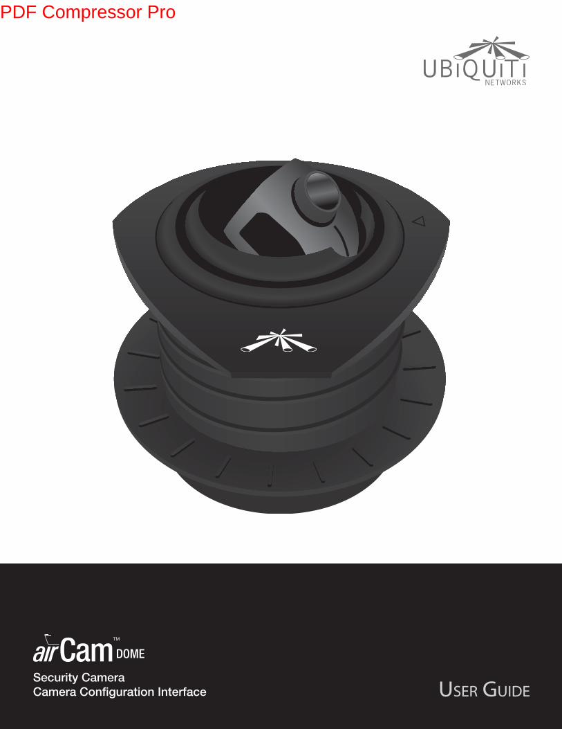
Security Camera
Camera Configuration Interface
PDF Compressor Pro
i
Table of Contents
Ubiquiti Networks, Inc.
airCam™ Dome User Guide
Table of Contents
Chapter 1: Product Overview . . . . . . . . . . . . . . . . . . . . . . . . . . . . . . . . . . . . . . . 1
Package Contents . . . . . . . . . . . . . . . . . . . . . . . . . . . . . . . . . . . . . . . . . . . . . . . . . . . . . . . . . . . . . . . . 1
Installation Requirements . . . . . . . . . . . . . . . . . . . . . . . . . . . . . . . . . . . . . . . . . . . . . . . . . . . . . . . . 1
System Requirements . . . . . . . . . . . . . . . . . . . . . . . . . . . . . . . . . . . . . . . . . . . . . . . . . . . . . . . . . . . . 1
Hardware Overview . . . . . . . . . . . . . . . . . . . . . . . . . . . . . . . . . . . . . . . . . . . . . . . . . . . . . . . . . . . . . . 1
Chapter 2: Installation . . . . . . . . . . . . . . . . . . . . . . . . . . . . . . . . . . . . . . . . . . . . . . 2
Installation . . . . . . . . . . . . . . . . . . . . . . . . . . . . . . . . . . . . . . . . . . . . . . . . . . . . . . . . . . . . . . . . . . . . . . . 2
Chapter 3: Using the Camera Configuration Interface . . . . . . . . . . . . . . . . 4
Adjusting the Camera View . . . . . . . . . . . . . . . . . . . . . . . . . . . . . . . . . . . . . . . . . . . . . . . . . . . . . . . 4
Navigation . . . . . . . . . . . . . . . . . . . . . . . . . . . . . . . . . . . . . . . . . . . . . . . . . . . . . . . . . . . . . . . . . . . . . . . 4
Tools . . . . . . . . . . . . . . . . . . . . . . . . . . . . . . . . . . . . . . . . . . . . . . . . . . . . . . . . . . . . . . . . . . . . . . . . . . . . . 5
Chapter 4: Main Tab . . . . . . . . . . . . . . . . . . . . . . . . . . . . . . . . . . . . . . . . . . . . . . . . 6
Status . . . . . . . . . . . . . . . . . . . . . . . . . . . . . . . . . . . . . . . . . . . . . . . . . . . . . . . . . . . . . . . . . . . . . . . . . . . . 6
Monitor . . . . . . . . . . . . . . . . . . . . . . . . . . . . . . . . . . . . . . . . . . . . . . . . . . . . . . . . . . . . . . . . . . . . . . . . . . 6
Chapter 5: Video Tab . . . . . . . . . . . . . . . . . . . . . . . . . . . . . . . . . . . . . . . . . . . . . . . 9
Using a microSD Card . . . . . . . . . . . . . . . . . . . . . . . . . . . . . . . . . . . . . . . . . . . . . . . . . . . . . . . . . . . . 9
Video Settings . . . . . . . . . . . . . . . . . . . . . . . . . . . . . . . . . . . . . . . . . . . . . . . . . . . . . . . . . . . . . . . . . . .11
RTSP Authentication . . . . . . . . . . . . . . . . . . . . . . . . . . . . . . . . . . . . . . . . . . . . . . . . . . . . . . . . . . . . .11
Video Recording . . . . . . . . . . . . . . . . . . . . . . . . . . . . . . . . . . . . . . . . . . . . . . . . . . . . . . . . . . . . . . . . .11
SD Card . . . . . . . . . . . . . . . . . . . . . . . . . . . . . . . . . . . . . . . . . . . . . . . . . . . . . . . . . . . . . . . . . . . . . . . . .12
Chapter 6: Network Tab . . . . . . . . . . . . . . . . . . . . . . . . . . . . . . . . . . . . . . . . . . . 14
Network Settings . . . . . . . . . . . . . . . . . . . . . . . . . . . . . . . . . . . . . . . . . . . . . . . . . . . . . . . . . . . . . . . .14
TCP Explicit Congestion Notification . . . . . . . . . . . . . . . . . . . . . . . . . . . . . . . . . . . . . . . . . . . . .15
Advanced Ethernet Settings . . . . . . . . . . . . . . . . . . . . . . . . . . . . . . . . . . . . . . . . . . . . . . . . . . . . .15
Chapter 7: Services Tab . . . . . . . . . . . . . . . . . . . . . . . . . . . . . . . . . . . . . . . . . . . 16
Ping Watchdog . . . . . . . . . . . . . . . . . . . . . . . . . . . . . . . . . . . . . . . . . . . . . . . . . . . . . . . . . . . . . . . . . .16
SNMP Agent. . . . . . . . . . . . . . . . . . . . . . . . . . . . . . . . . . . . . . . . . . . . . . . . . . . . . . . . . . . . . . . . . . . . .17
Web Server . . . . . . . . . . . . . . . . . . . . . . . . . . . . . . . . . . . . . . . . . . . . . . . . . . . . . . . . . . . . . . . . . . . . . .17
SSH Server . . . . . . . . . . . . . . . . . . . . . . . . . . . . . . . . . . . . . . . . . . . . . . . . . . . . . . . . . . . . . . . . . . . . . .17
Telnet Server . . . . . . . . . . . . . . . . . . . . . . . . . . . . . . . . . . . . . . . . . . . . . . . . . . . . . . . . . . . . . . . . . . . .17
NTP Client . . . . . . . . . . . . . . . . . . . . . . . . . . . . . . . . . . . . . . . . . . . . . . . . . . . . . . . . . . . . . . . . . . . . . . .17
Dynamic DNS . . . . . . . . . . . . . . . . . . . . . . . . . . . . . . . . . . . . . . . . . . . . . . . . . . . . . . . . . . . . . . . . . . .18
System Log . . . . . . . . . . . . . . . . . . . . . . . . . . . . . . . . . . . . . . . . . . . . . . . . . . . . . . . . . . . . . . . . . . . . . .18
PDF Compressor Pro
ii
Table of Contents
Ubiquiti Networks, Inc.
airCam™ Dome User Guide
Chapter 8: System Tab . . . . . . . . . . . . . . . . . . . . . . . . . . . . . . . . . . . . . . . . . . . . 19
Device . . . . . . . . . . . . . . . . . . . . . . . . . . . . . . . . . . . . . . . . . . . . . . . . . . . . . . . . . . . . . . . . . . . . . . . . . .19
Date Settings . . . . . . . . . . . . . . . . . . . . . . . . . . . . . . . . . . . . . . . . . . . . . . . . . . . . . . . . . . . . . . . . . . . .19
System Accounts . . . . . . . . . . . . . . . . . . . . . . . . . . . . . . . . . . . . . . . . . . . . . . . . . . . . . . . . . . . . . . . .19
Maintenance . . . . . . . . . . . . . . . . . . . . . . . . . . . . . . . . . . . . . . . . . . . . . . . . . . . . . . . . . . . . . . . . . . . .20
Appendix A: Specifications . . . . . . . . . . . . . . . . . . . . . . . . . . . . . . . . . . . . . . . . 22
Appendix B: Safety Notices . . . . . . . . . . . . . . . . . . . . . . . . . . . . . . . . . . . . . . . . 23
Electrical Safety Information . . . . . . . . . . . . . . . . . . . . . . . . . . . . . . . . . . . . . . . . . . . . . . . . . . . . .23
Appendix C: Warranty . . . . . . . . . . . . . . . . . . . . . . . . . . . . . . . . . . . . . . . . . . . . . 24
General Warranty . . . . . . . . . . . . . . . . . . . . . . . . . . . . . . . . . . . . . . . . . . . . . . . . . . . . . . . . . . . . . . . .24
Appendix D: Compliance Information . . . . . . . . . . . . . . . . . . . . . . . . . . . . . 25
Installer Compliance Responsibility . . . . . . . . . . . . . . . . . . . . . . . . . . . . . . . . . . . . . . . . . . . . . .25
FCC . . . . . . . . . . . . . . . . . . . . . . . . . . . . . . . . . . . . . . . . . . . . . . . . . . . . . . . . . . . . . . . . . . . . . . . . . . . . .25
Industry Canada . . . . . . . . . . . . . . . . . . . . . . . . . . . . . . . . . . . . . . . . . . . . . . . . . . . . . . . . . . . . . . . . .25
Class B Korea . . . . . . . . . . . . . . . . . . . . . . . . . . . . . . . . . . . . . . . . . . . . . . . . . . . . . . . . . . . . . . . . . . . .25
CE Marking . . . . . . . . . . . . . . . . . . . . . . . . . . . . . . . . . . . . . . . . . . . . . . . . . . . . . . . . . . . . . . . . . . . . . .25
RoHS/WEEE Compliance Statement . . . . . . . . . . . . . . . . . . . . . . . . . . . . . . . . . . . . . . . . . . . . . .26
Appendix E: Declaration of Conformity . . . . . . . . . . . . . . . . . . . . . . . . . . . . 27
Appendix F: Contact Information . . . . . . . . . . . . . . . . . . . . . . . . . . . . . . . . . . 28
Ubiquiti Networks Support . . . . . . . . . . . . . . . . . . . . . . . . . . . . . . . . . . . . . . . . . . . . . . . . . . . . . .28
PDF Compressor Pro
1
Chapter 1: Product OverviewairCam™ Dome User Guide
Ubiquiti Networks, Inc.
Chapter 1: Product Overview
Thank you for purchasing the airCam™ Dome, by Ubiquiti
Networks.
This User Guide is designed to provide instructions about
the installation of the airCam Dome and to provide details
about how to install the camera and use the camera
configuration interface.
The airCam Dome includes the airVision™ software.
airVision is a comprehensive camera management
software solution from Ubiquiti Networks, Inc. that is
designed to work with Ubiquiti’s airCam product line. The
software interface design is based on the popular and
easy-to-use UniFi™ software interface. For instructions on
using the airVision software, refer to the airVision User
Guide on the CD-ROM.
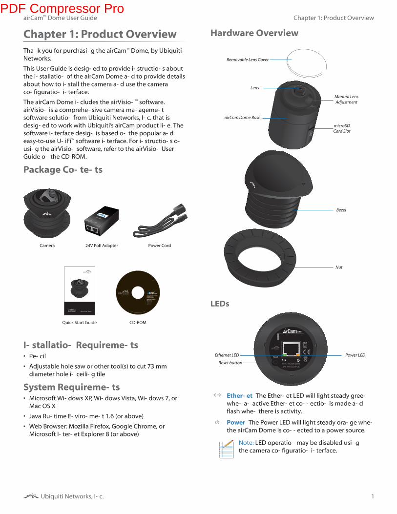
Package Contents
Camera 24V PoE Adapter Power Cord
Security Camera
Quick Start Guide CD-ROM
Installation Requirements• Pencil
• Adjustable hole saw or other tool(s) to cut 73 mm
diameter hole in ceiling tile
System Requirements• Microsoft Windows XP, Windows Vista, Windows 7, or
Mac OS X
• Java Runtime Environment 1.6 (or above)
• Web Browser: Mozilla Firefox, Google Chrome, or
Microsoft Internet Explorer 8 (or above)
Hardware Overview
Lens
Bezel
Nut
airCam Dome Base
Removable Lens Cover
microSD
Card Slot
Manual Lens
Adjustment
LEDs
Ethernet LED Power LED
Reset button
Ethernet The Ethernet LED will light steady green
when an active Ethernet connection is made and
flash when there is activity.
Power The Power LED will light steady orange when
the airCam Dome is connected to a power source.
Note: LED operation may be disabled using
the camera configuration interface.
PDF Compressor Pro
2
Chapter 2: Installation
Ubiquiti Networks, Inc.
airCam™ Dome User Guide
Chapter 2: Installation
The airCam Dome is designed to be mounted in a ceiling.
Perform the following steps to install the airCam Dome.
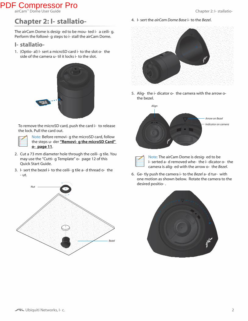
Installation1. (Optional) Insert a microSD card into the slot on the
side of the camera until it locks into the slot.
To remove the microSD card, push the card in to release
the lock. Pull the card out.
Note: Before removing the microSD card, follow
the steps under “Removing the microSD Card”
on page 11.
2. Cut a 73 mm diameter hole through the ceiling tile. You
may use the “Cutting Template” on page 12 of this
Quick Start Guide.
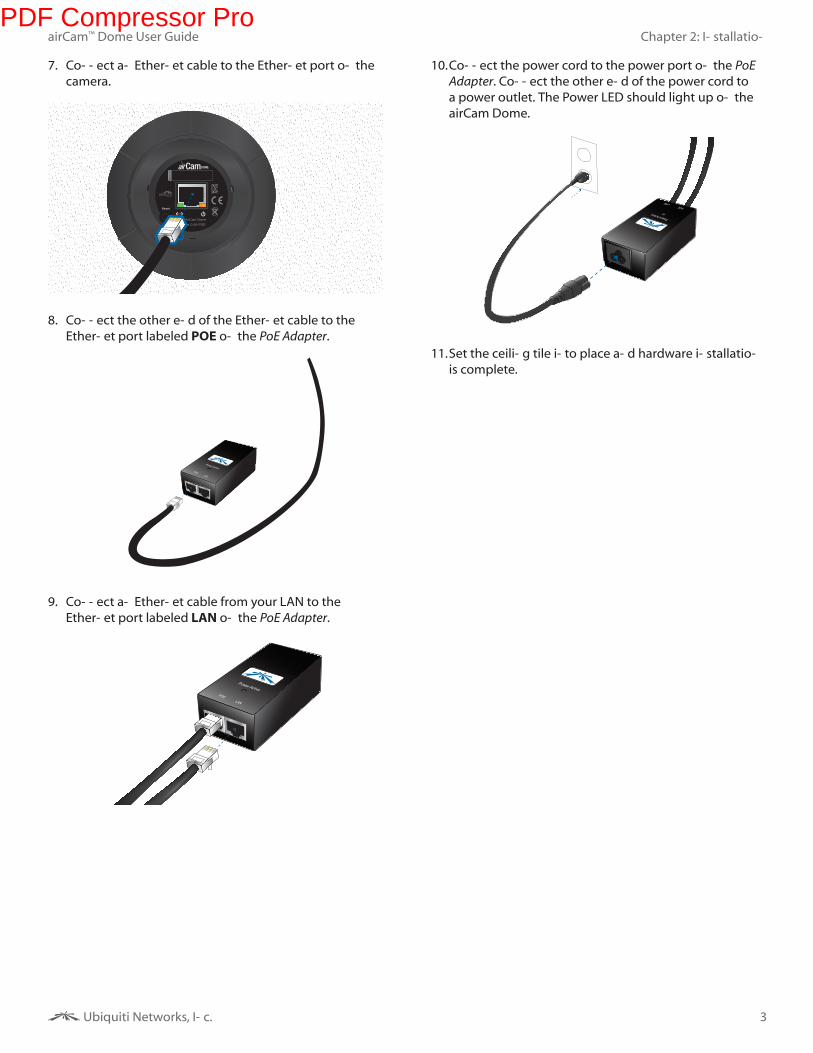
3. Insert the bezel into the ceiling tile and thread on the
nut.
Nut
Bezel
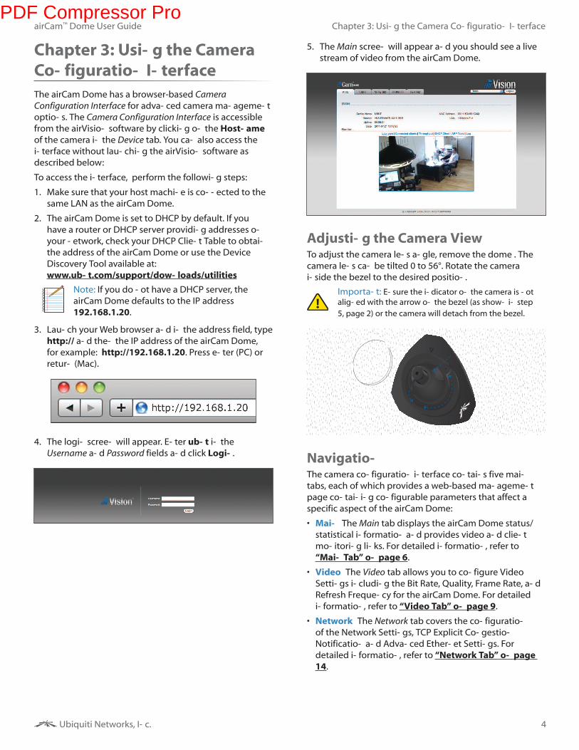
4. Insert the airCam Dome Base into the Bezel.
5. Align the indicator on the camera with the arrow on
the bezel.
Arrow on Bezel
Align
Indicator on camera
Note: The airCam Dome is designed to be
inserted and removed when the indicator on the
camera is aligned with the arrow on the Bezel.
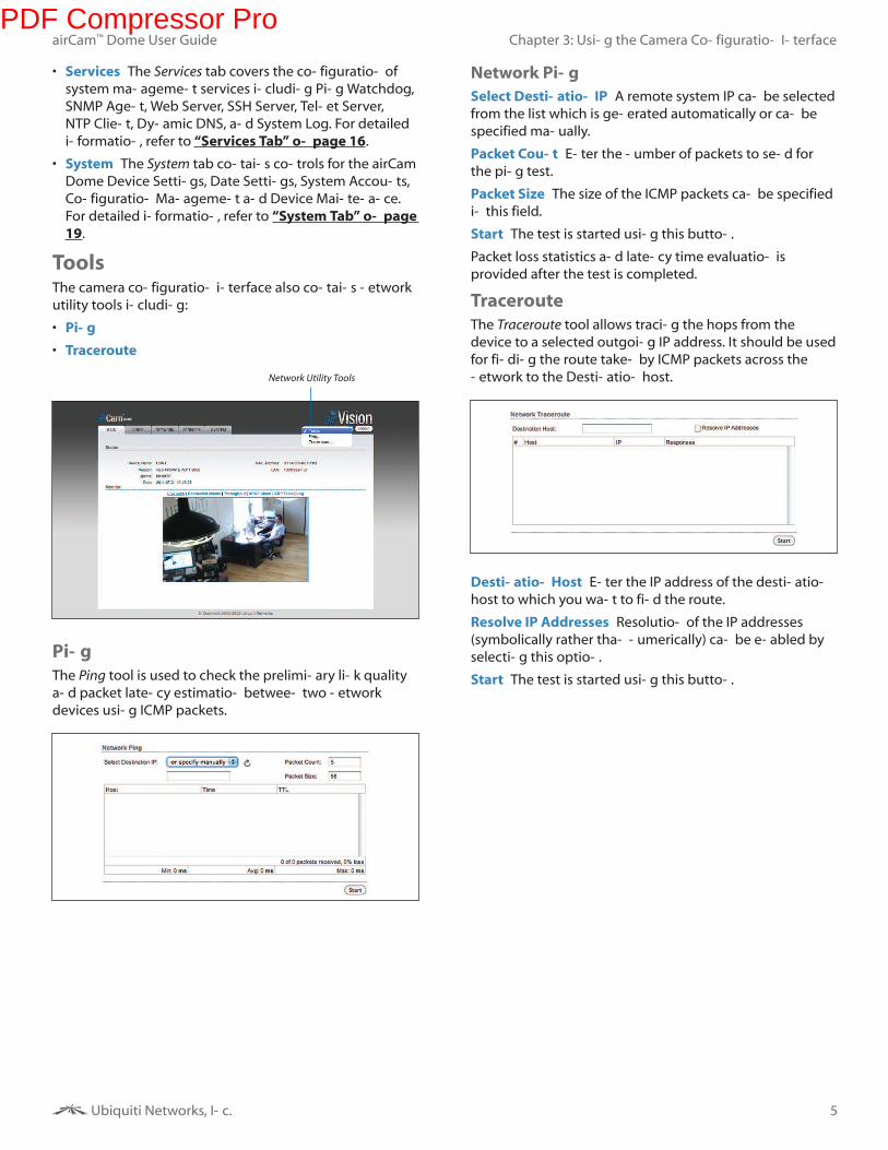
6. Gently push the camera into the Bezel and turn with
one motion as shown below. Rotate the camera to the desired position.
PDF Compressor Pro
3
Chapter 2: Installation
Ubiquiti Networks, Inc.
airCam™ Dome User Guide
7. Connect an Ethernet cable to the Ethernet port on the
camera.
8. Connect the other end of the Ethernet cable to the
Ethernet port labeled POE on the PoE Adapter.
9. Connect an Ethernet cable from your LAN to the
Ethernet port labeled LAN on the PoE Adapter.
10. Connect the power cord to the power port on the PoE
Adapter. Connect the other end of the power cord to
a power outlet. The Power LED should light up on the
airCam Dome.
11. Set the ceiling tile into place and hardware installation
is complete.
PDF Compressor Pro
4
Chapter 3: Using the Camera Configuration Interface
Ubiquiti Networks, Inc.
airCam™ Dome User Guide
Chapter 3: Using the Camera
Configuration Interface
The airCam Dome has a browser-based Camera
Configuration Interface for advanced camera management
options. The Camera Configuration Interface is accessible
from the airVision software by clicking on the Hostname
of the camera in the Device tab. You can also access the
interface without launching the airVision software as
described below:
To access the interface, perform the following steps:
1. Make sure that your host machine is connected to the
same LAN as the airCam Dome.
2. The airCam Dome is set to DHCP by default. If you
have a router or DHCP server providing addresses on
your network, check your DHCP Client Table to obtain
the address of the airCam Dome or use the Device
Discovery Tool available at:
www.ubnt.com/support/downloads/utilities
Note: If you do not have a DHCP server, the
airCam Dome defaults to the IP address
192.168.1.20.
3. Launch your Web browser and in the address field, type
http:// and then the IP address of the airCam Dome,
for example: http://192.168.1.20. Press enter (PC) or
return (Mac).
4. The login screen will appear. Enter ubnt in the
Username and Password fields and click Login.
5. The Main screen will appear and you should see a live
stream of video from the airCam Dome.
Adjusting the Camera ViewTo adjust the camera lens angle, remove the dome . The
camera lens can be tilted 0 to 56°. Rotate the camera
inside the bezel to the desired position.
Important: Ensure the indicator on the camera is not
aligned with the arrow on the bezel (as shown in step
5, page 2) or the camera will detach from the bezel.
NavigationThe camera configuration interface contains five main
tabs, each of which provides a web-based management
page containing configurable parameters that affect a
specific aspect of the airCam Dome:
• Main The Main tab displays the airCam Dome status/
statistical information and provides video and client
monitoring links. For detailed information, refer to
“Main Tab” on page 6.
• Video The Video tab allows you to configure Video
Settings including the Bit Rate, Quality, Frame Rate, and
Refresh Frequency for the airCam Dome. For detailed
information, refer to “Video Tab” on page 9.
• Network The Network tab covers the configuration
of the Network Settings, TCP Explicit Congestion
Notification and Advanced Ethernet Settings. For
detailed information, refer to “Network Tab” on page
14.
PDF Compressor Pro
5
Chapter 3: Using the Camera Configuration Interface
Ubiquiti Networks, Inc.
airCam™ Dome User Guide
• Services The Services tab covers the configuration of
system management services including Ping Watchdog,
SNMP Agent, Web Server, SSH Server, Telnet Server,
NTP Client, Dynamic DNS, and System Log. For detailed
information, refer to “Services Tab” on page 16.
• System The System tab contains controls for the airCam
Dome Device Settings, Date Settings, System Accounts,
Configuration Management and Device Maintenance.
For detailed information, refer to “System Tab” on page
19.
ToolsThe camera configuration interface also contains network
utility tools including:
• Ping
• Traceroute
Network Utility Tools
Ping
The Ping tool is used to check the preliminary link quality
and packet latency estimation between two network
devices using ICMP packets.
Network Ping
Select Destination IP A remote system IP can be selected
from the list which is generated automatically or can be
specified manually.
Packet Count Enter the number of packets to send for
the ping test.
Packet Size The size of the ICMP packets can be specified
in this field.
Start The test is started using this button.
Packet loss statistics and latency time evaluation is
provided after the test is completed.
Traceroute
The Traceroute tool allows tracing the hops from the
device to a selected outgoing IP address. It should be used
for finding the route taken by ICMP packets across the
network to the Destination host.
Destination Host Enter the IP address of the destination
host to which you want to find the route.
Resolve IP Addresses Resolution of the IP addresses
(symbolically rather than numerically) can be enabled by
selecting this option.
Start The test is started using this button.
PDF Compressor Pro
6
Chapter 4: Main Tab
Ubiquiti Networks, Inc.
airCam™ Dome User Guide
Chapter 4: Main Tab
The Main tab displays status/statistical information and
provides video and client monitoring links.
Status
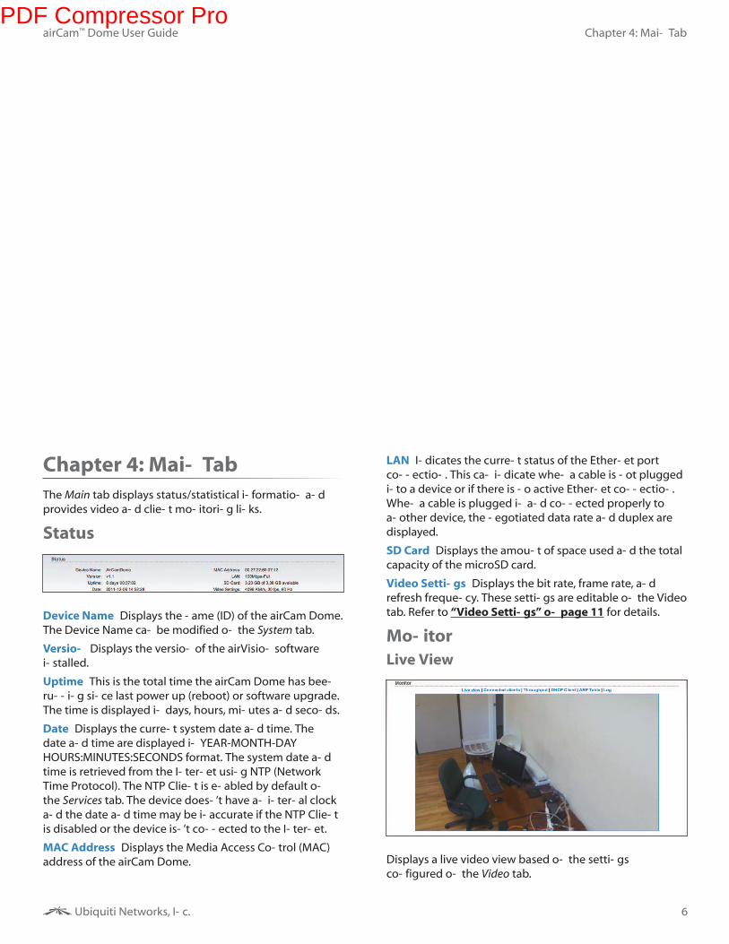
Device Name Displays the name (ID) of the airCam Dome.
The Device Name can be modified on the System tab.
Version Displays the version of the airVision software
installed.
Uptime This is the total time the airCam Dome has been
running since last power up (reboot) or software upgrade.
The time is displayed in days, hours, minutes and seconds.
Date Displays the current system date and time. The
date and time are displayed in YEAR-MONTH-DAY
HOURS:MINUTES:SECONDS format. The system date and
time is retrieved from the Internet using NTP (Network
Time Protocol). The NTP Client is enabled by default on
the Services tab. The device doesn’t have an internal clock
and the date and time may be inaccurate if the NTP Client
is disabled or the device isn’t connected to the Internet.
MAC Address Displays the Media Access Control (MAC)
address of the airCam Dome.
LAN Indicates the current status of the Ethernet port
connection. This can indicate when a cable is not plugged
into a device or if there is no active Ethernet connection.
When a cable is plugged in and connected properly to
another device, the negotiated data rate and duplex are
displayed.
SD Card Displays the amount of space used and the total
capacity of the microSD card.
Video Settings Displays the bit rate, frame rate, and
refresh frequency. These settings are editable on the Video
tab. Refer to “Video Settings” on page 11 for details.
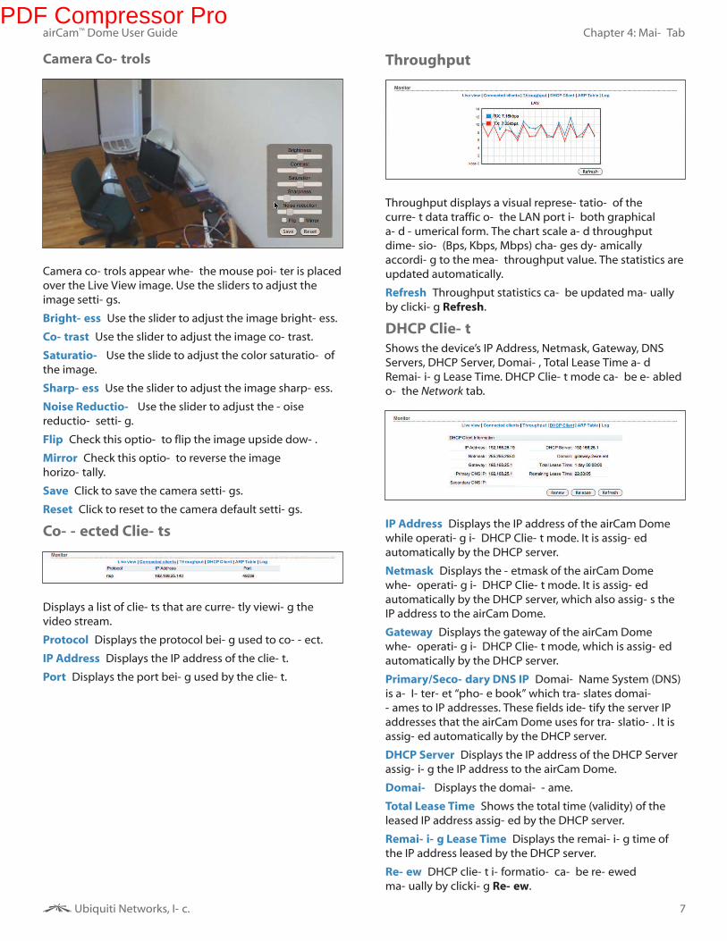
Monitor
Live View
Displays a live video view based on the settings
configured on the Video tab.
PDF Compressor Pro
7
Chapter 4: Main Tab
Ubiquiti Networks, Inc.
airCam™ Dome User Guide
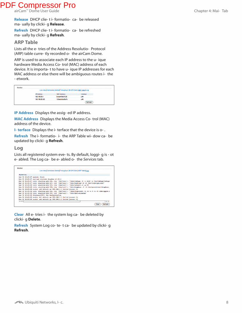
Camera Controls
Camera controls appear when the mouse pointer is placed
over the Live View image. Use the sliders to adjust the
image settings.
Brightness Use the slider to adjust the image brightness.
Contrast Use the slider to adjust the image contrast.
Saturation Use the slide to adjust the color saturation of
the image.
Sharpness Use the slider to adjust the image sharpness.
Noise Reduction Use the slider to adjust the noise
reduction setting.
Flip Check this option to flip the image upside down.
Mirror Check this option to reverse the image
horizontally.
Save Click to save the camera settings.
Reset Click to reset to the camera default settings.
Connected Clients
Displays a list of clients that are currently viewing the
video stream.
Protocol Displays the protocol being used to connect.
IP Address Displays the IP address of the client.
Port Displays the port being used by the client.
Throughput
Throughput displays a visual representation of the
current data traffic on the LAN port in both graphical
and numerical form. The chart scale and throughput
dimension (Bps, Kbps, Mbps) changes dynamically
according to the mean throughput value. The statistics are
updated automatically.
Refresh Throughput statistics can be updated manually
by clicking Refresh.
DHCP Client
Shows the device’s IP Address, Netmask, Gateway, DNS
Servers, DHCP Server, Domain, Total Lease Time and
Remaining Lease Time. DHCP Client mode can be enabled
on the Network tab.
IP Address Displays the IP address of the airCam Dome
while operating in DHCP Client mode. It is assigned
automatically by the DHCP server.
Netmask Displays the netmask of the airCam Dome
when operating in DHCP Client mode. It is assigned
automatically by the DHCP server, which also assigns the
IP address to the airCam Dome.
Gateway Displays the gateway of the airCam Dome
when operating in DHCP Client mode, which is assigned
automatically by the DHCP server.
Primary/Secondary DNS IP Domain Name System (DNS)
is an Internet “phone book” which translates domain
names to IP addresses. These fields identify the server IP
addresses that the airCam Dome uses for translation. It is
assigned automatically by the DHCP server.
DHCP Server Displays the IP address of the DHCP Server
assigning the IP address to the airCam Dome.
Domain Displays the domain name.
Total Lease Time Shows the total time (validity) of the
leased IP address assigned by the DHCP server.
Remaining Lease Time Displays the remaining time of
the IP address leased by the DHCP server.
Renew DHCP client information can be renewed
manually by clicking Renew.
PDF Compressor Pro
8
Chapter 4: Main Tab
Ubiquiti Networks, Inc.
airCam™ Dome User Guide
Release DHCP client information can be released
manually by clicking Release.
Refresh DHCP client information can be refreshed
manually by clicking Refresh.
ARP Table
Lists all the entries of the Address Resolution Protocol
(ARP) table currently recorded on the airCam Dome.
ARP is used to associate each IP address to the unique
hardware Media Access Control (MAC) address of each
device. It is important to have unique IP addresses for each
MAC address or else there will be ambiguous routes in the
network.
IP Address Displays the assigned IP address.
MAC Address Displays the Media Access Control (MAC)
address of the device.
Interface Displays the interface that the device is on.
Refresh The information in the ARP Table window can be
updated by clicking Refresh.
Log
Lists all registered system events. By default, logging is not
enabled. The Log can be enabled on the Services tab.
Clear All entries in the system log can be deleted by
clicking Delete.
Refresh System Log content can be updated by clicking
Refresh.
PDF Compressor Pro
9
Chapter 5: Video Tab
Ubiquiti Networks, Inc.
airCam™ Dome User Guide
Chapter 5: Video Tab
The Video tab allows you to configure basic Video Settings
including the Bit Rate, Quality Frame Rate, and Refresh
Frequency settings for the airCam Dome. If you are
using an optional microSD card (not included), you can
configure Video Recording and SD card options from this
screen.
Using a microSD CardYou can record video on a microSD card. The recording
options for recording on the microSD card are completely
separate from the airVision software recording options.
microSD card recording is configurable only in the Camera
Configuration Interface.
If you need to insert a microSD card and haven’t installed
your airCam Dome yet, refer to “Installation” on page 2.
If you’ve already installed your airCam Dome but need to
remove the airCam Dome Camera Base from the Bezel to
insert a microSD card, perform the following steps:
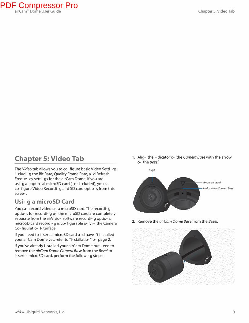
1. Align the indicator on the Camera Base with the arrow
on the Bezel.
Arrow on bezel
Align
Indicator on Camera Base
2. Remove the airCam Dome Base from the Bezel.
PDF Compressor Pro
10
Chapter 5: Video Tab
Ubiquiti Networks, Inc.
airCam™ Dome User Guide
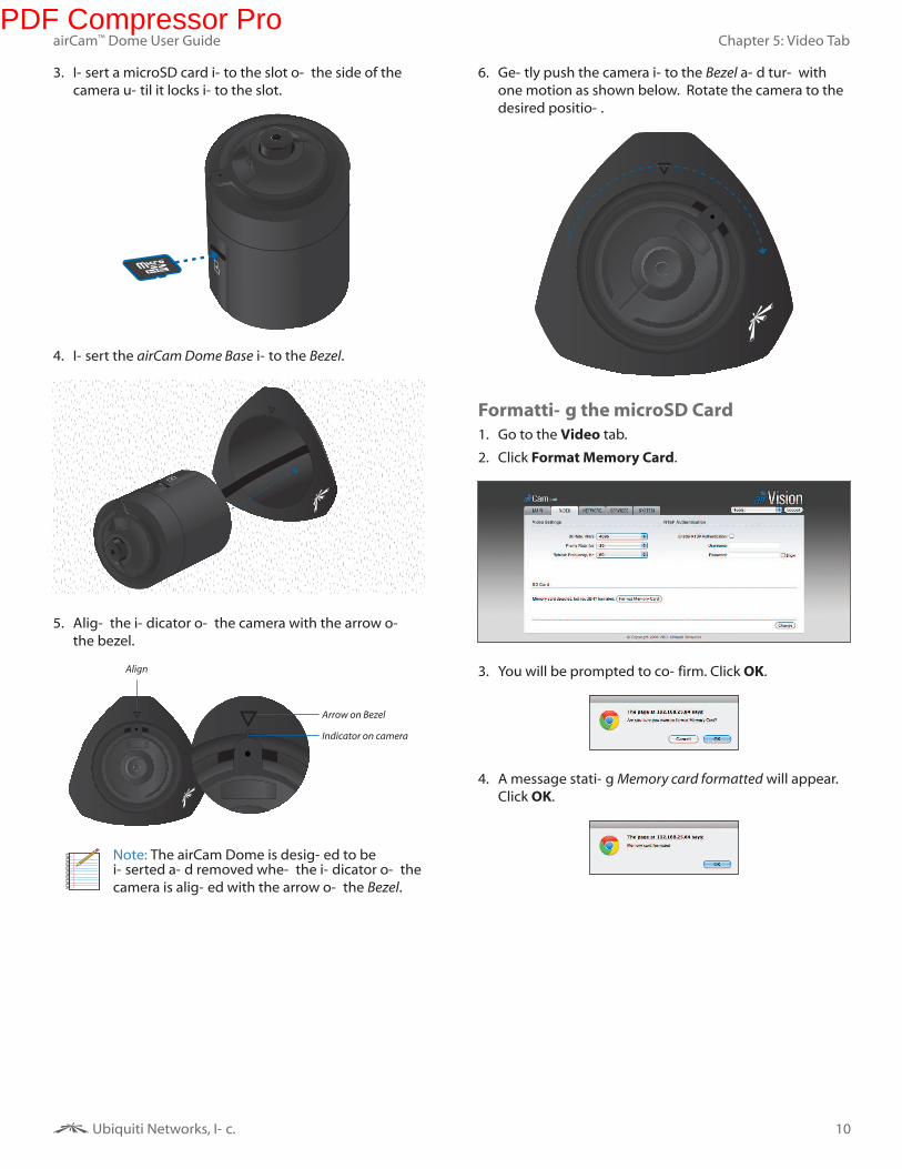
3. Insert a microSD card into the slot on the side of the
camera until it locks into the slot.
4. Insert the airCam Dome Base into the Bezel.
5. Align the indicator on the camera with the arrow on
the bezel.
Arrow on Bezel
Align
Indicator on camera
Note: The airCam Dome is designed to be inserted and removed when the indicator on the
camera is aligned with the arrow on the Bezel.
6. Gently push the camera into the Bezel and turn with
one motion as shown below. Rotate the camera to the desired position.
Formatting the microSD Card
1. Go to the Video tab.
2. Click Format Memory Card.
3. You will be prompted to confirm. Click OK.
4. A message stating Memory card formatted will appear.
Click OK.
PDF Compressor Pro
11
Chapter 5: Video Tab
Ubiquiti Networks, Inc.
airCam™ Dome User Guide
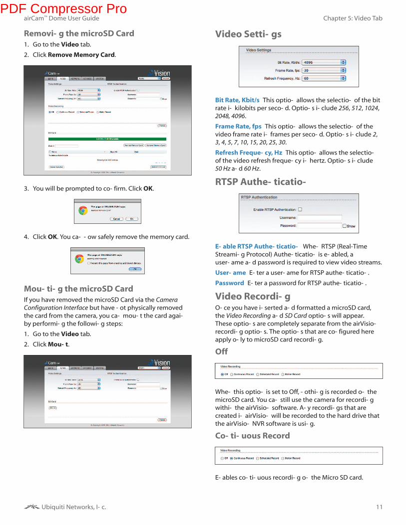
Removing the microSD Card
1. Go to the Video tab.
2. Click Remove Memory Card.
3. You will be prompted to confirm. Click OK.
4. Click OK. You can now safely remove the memory card.
Mounting the microSD Card
If you have removed the microSD Card via the Camera
Configuration Interface but have not physically removed
the card from the camera, you can mount the card again
by performing the following steps:
1. Go to the Video tab.
2. Click Mount.
Video Settings
Bit Rate, Kbit/s This option allows the selection of the bit
rate in kilobits per second. Options include 256, 512, 1024,
2048, 4096.
Frame Rate, fps This option allows the selection of the
video frame rate in frames per second. Options include 2,
3, 4, 5, 7, 10, 15, 20, 25, 30.
Refresh Frequency, Hz This option allows the selection
of the video refresh frequency in hertz. Options include
50 Hz and 60 Hz.
RTSP Authentication
Enable RTSP Authentication When RTSP (Real-Time
Streaming Protocol) Authentication is enabled, a
username and password is required to view video streams.
Username Enter a username for RTSP authentication.
Password Enter a password for RTSP authentication.
Video RecordingOnce you have inserted and formatted a microSD card,
the Video Recording and SD Card options will appear.
These options are completely separate from the airVision
recording options. The options that are configured here
apply only to microSD card recording.
Off
When this option is set to Off, nothing is recorded on the
microSD card. You can still use the camera for recording
within the airVision software. Any recordings that are
created in airVision will be recorded to the hard drive that
the airVision NVR software is using.
Continuous Record
Enables continuous recording on the Micro SD card.
PDF Compressor Pro
12
Chapter 5: Video Tab
Ubiquiti Networks, Inc.
airCam™ Dome User Guide
Scheduled Record
Allows you to define a schedule for recording. Select
which days that you want scheduled recording enabled
and a start and end time.
Creating a Scheduled Recording
1. Select Scheduled Record.
2. Click Add New Row.
3. Select the days of the week that you want recording
enabled by placing a check mark underneath the day.
4. Enter the start time and stop time in 24-hour format.
5. Select Enabled.
6. Click Set.
7. Click Change.
8. Click Apply.
Deleting a Scheduled Recording
1. Click on an existing row.
2. Click Delete.
3. Click Yes when prompted “Are you sure you want to
delete schedule event?”.
4. Click Change.
5. Click Apply.
Motion Record
Select Full Frame Selects the entire camera frame for
motion detection.
New Selection Allows you to select a specific area of the
frame for motion detection. Click and hold the area of the
image that you want to select. Drag and adjust the box to
select the area where you want to detect motion.
Sensitivity Use the slider to adjust the sensitivity of the
motion detection. Sensitivity values range from 100 to
1. Higher numbers increase the sensitivity, requiring less
motion to trigger a recording.
Higher SensitivityLess Motion Required
Lower SensitivityMore Motion Required
Enabling Motion Recording
1. Select Motion Record.
2. Click New Selection (or Select Full Frame to select the
entire image).
3. To define the motion detection area, click and drag to
create the motion detection frame. To adjust the size
of the frame, place the mouse over a mid or end point
and then click and drag. To move the frame position,
click and drag an area of the motion detection frame
that is not a mid or end point.
4. Select the Sensitivity level. Higher numbers increase the
sensitivity, requiring less motion to trigger a recording.
5. Click Change.
6. Click Apply.
SD Card
X of X available Displays the amount of space used and
the total capacity of the microSD card.
Search Allows you to search recordings for specific search
criteria. Any text that is entered is used as real-time search
criteria and anything that doesn’t match the entered
characters will be removed from the view. Delete the
search string to return to a normal view.
PDF Compressor Pro
13
Chapter 5: Video Tab
Ubiquiti Networks, Inc.
airCam™ Dome User Guide
Format Memory Card Use this option to format a new
microSD card.
Remove Memory Card Use this option to safely remove a
microSD card.
Name Displays the name of the recording. Place the
cursor over the file name to see a preview image from the
recording. Double-click the name to download the file to
your computer. Once the file downloads to the computer
you can open it with a video player that supports .avi files.
Size Displays the size of the recording.
Date Displays the date and time that the recording took
place.
Delete Selected Permanently deletes selected
recordings.
Refresh File List Use to refresh the list of recordings to
show any newly created recordings.
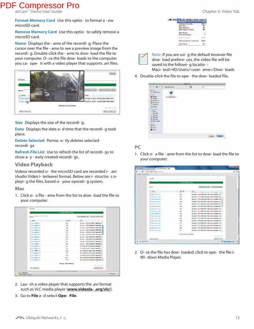
Video Playback
Videos recorded on the microSD card are recorded in .avi
(Audio Video Interleave) format. Below are instructions on
playing the files, based on your operating system.
Mac
1. Click on a file name from the list to download the file to
your computer.
2. Launch a video player that supports the .avi format
such as VLC media player (www.videolan.org/vlc/).
3. Go to File and select Open File.
Note: If you are using the default browser file
download preferences, the video file will be
saved to the following location:
Macintosh HD/Users/<username>/Downloads
4. Double-click the file to open the downloaded file.
PC
1. Click on a file name from the list to download the file to
your computer.
2. Once the file has downloaded, click to open the file in
Windows Media Player.
PDF Compressor Pro
14
Chapter 6: Network Tab
Ubiquiti Networks, Inc.
airCam™ Dome User Guide
Chapter 6: Network Tab
The Network tab covers the configuration of the Network
Settings, TCP Explicit Congestion Notification, and
Advanced Ethernet Settings.
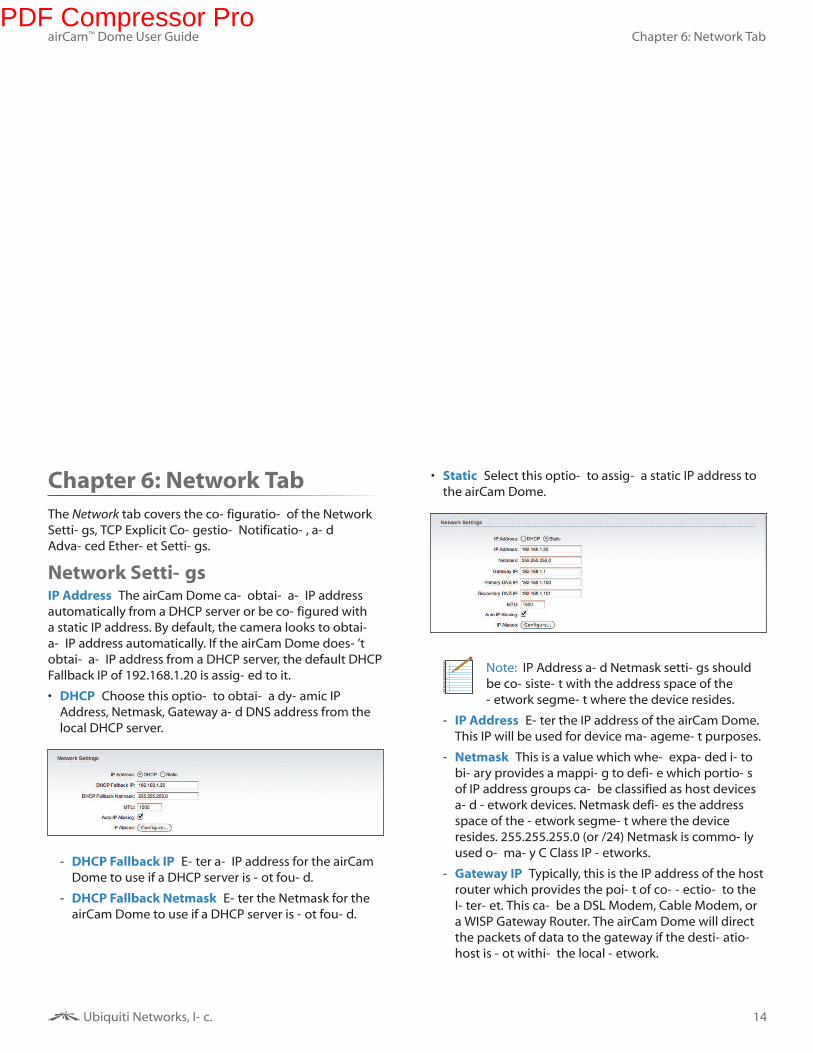
Network SettingsIP Address The airCam Dome can obtain an IP address
automatically from a DHCP server or be configured with
a static IP address. By default, the camera looks to obtain
an IP address automatically. If the airCam Dome doesn’t
obtain an IP address from a DHCP server, the default DHCP
Fallback IP of 192.168.1.20 is assigned to it.
• DHCP Choose this option to obtain a dynamic IP
Address, Netmask, Gateway and DNS address from the
local DHCP server.
- DHCP Fallback IP Enter an IP address for the airCam
Dome to use if a DHCP server is not found.
- DHCP Fallback Netmask Enter the Netmask for the
airCam Dome to use if a DHCP server is not found.
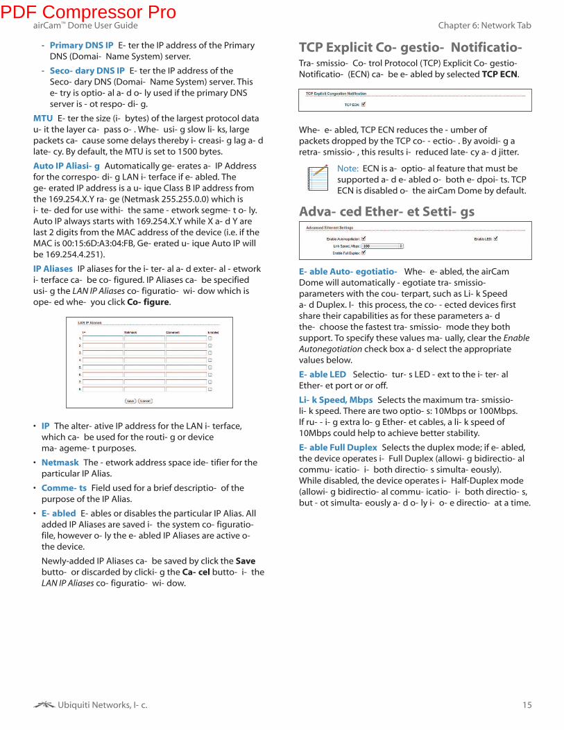
• Static Select this option to assign a static IP address to
the airCam Dome.
Note: IP Address and Netmask settings should
be consistent with the address space of the
network segment where the device resides.
- IP Address Enter the IP address of the airCam Dome.
This IP will be used for device management purposes.
- Netmask This is a value which when expanded into
binary provides a mapping to define which portions
of IP address groups can be classified as host devices
and network devices. Netmask defines the address
space of the network segment where the device
resides. 255.255.255.0 (or /24) Netmask is commonly
used on many C Class IP networks.
- Gateway IP Typically, this is the IP address of the host
router which provides the point of connection to the
Internet. This can be a DSL Modem, Cable Modem, or
a WISP Gateway Router. The airCam Dome will direct
the packets of data to the gateway if the destination
host is not within the local network.
PDF Compressor Pro
15
Chapter 6: Network Tab
Ubiquiti Networks, Inc.
airCam™ Dome User Guide
- Primary DNS IP Enter the IP address of the Primary
DNS (Domain Name System) server.
- Secondary DNS IP Enter the IP address of the
Secondary DNS (Domain Name System) server. This
entry is optional and only used if the primary DNS
server is not responding.
MTU Enter the size (in bytes) of the largest protocol data
unit the layer can pass on. When using slow links, large
packets can cause some delays thereby increasing lag and
latency. By default, the MTU is set to 1500 bytes.
Auto IP Aliasing Automatically generates an IP Address
for the corresponding LAN interface if enabled. The
generated IP address is a unique Class B IP address from
the 169.254.X.Y range (Netmask 255.255.0.0) which is
intended for use within the same network segment only.
Auto IP always starts with 169.254.X.Y while X and Y are
last 2 digits from the MAC address of the device (i.e. if the
MAC is 00:15:6D:A3:04:FB, Generated unique Auto IP will
be 169.254.4.251).
IP Aliases IP aliases for the internal and external network
interface can be configured. IP Aliases can be specified
using the LAN IP Aliases configuration window which is
opened when you click Configure.
• IP The alternative IP address for the LAN interface,
which can be used for the routing or device
management purposes.
• Netmask The network address space identifier for the
particular IP Alias.
• Comments Field used for a brief description of the
purpose of the IP Alias.
• Enabled Enables or disables the particular IP Alias. All
added IP Aliases are saved in the system configuration
file, however only the enabled IP Aliases are active on
the device.
Newly-added IP Aliases can be saved by click the Save
button or discarded by clicking the Cancel button in the
LAN IP Aliases configuration window.
TCP Explicit Congestion NotificationTransmission Control Protocol (TCP) Explicit Congestion
Notification (ECN) can be enabled by selected TCP ECN.
When enabled, TCP ECN reduces the number of
packets dropped by the TCP connection. By avoiding a
retransmission, this results in reduced latency and jitter.
Note: ECN is an optional feature that must be
supported and enabled on both endpoints. TCP
ECN is disabled on the airCam Dome by default.
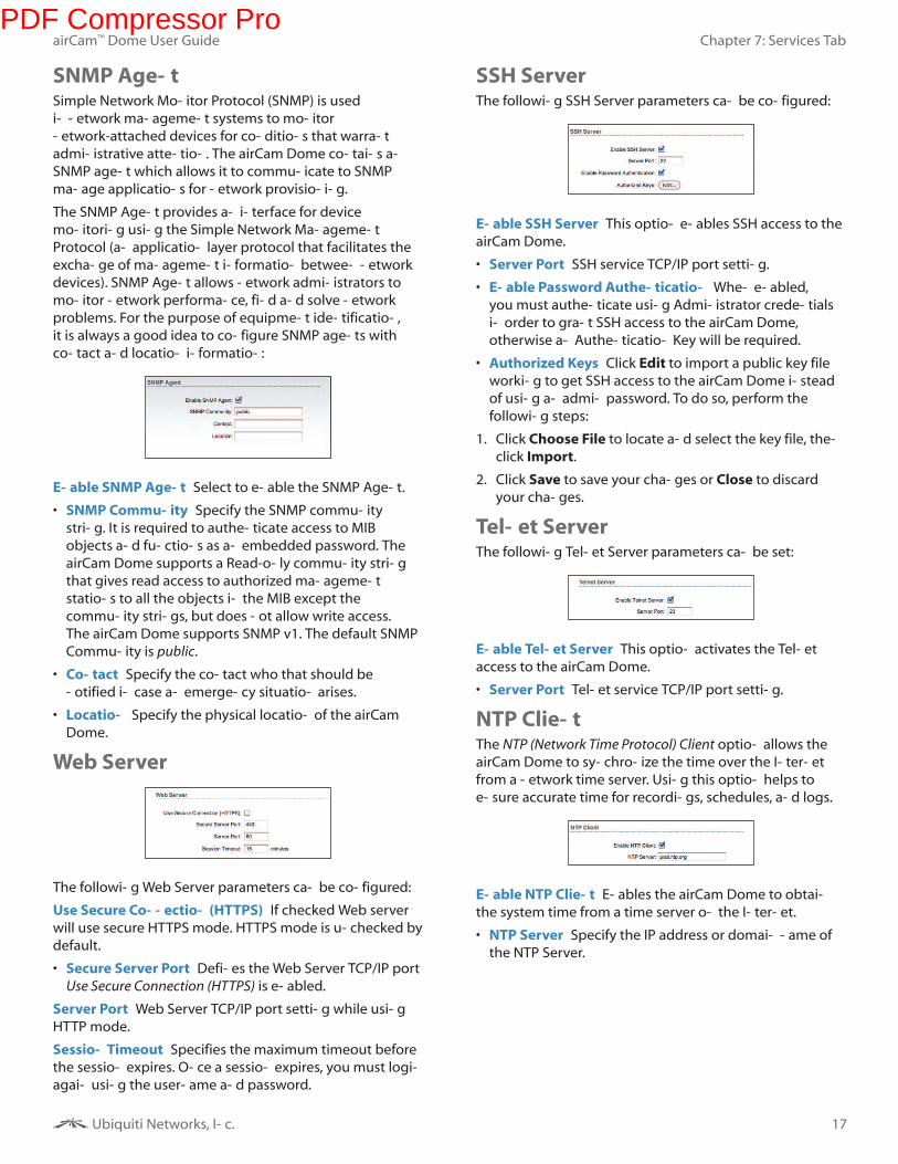
Advanced Ethernet Settings
Enable Autonegotiation When enabled, the airCam
Dome will automatically negotiate transmission
parameters with the counterpart, such as Link Speed
and Duplex. In this process, the connected devices first
share their capabilities as for these parameters and
then choose the fastest transmission mode they both
support. To specify these values manually, clear the Enable
Autonegotiation check box and select the appropriate
values below.
Enable LED Selection turns LED next to the internal
Ethernet port or or off.
Link Speed, Mbps Selects the maximum transmission
link speed. There are two options: 10Mbps or 100Mbps.
If running extra long Ethernet cables, a link speed of
10Mbps could help to achieve better stability.
Enable Full Duplex Selects the duplex mode; if enabled,
the device operates in Full Duplex (allowing bidirectional
communication in both directions simultaneously).
While disabled, the device operates in Half-Duplex mode
(allowing bidirectional communication in both directions,
but not simultaneously and only in one direction at a time.
PDF Compressor Pro
16
Chapter 7: Services Tab
Ubiquiti Networks, Inc.
airCam™ Dome User Guide
Chapter 7: Services Tab
The Services tab covers the configuration of system
management services including Ping Watchdog, SNMP
Agent, Web Server, SSH Server, Telnet Server, NTP Client,
Dynamic DNS, and System Log.
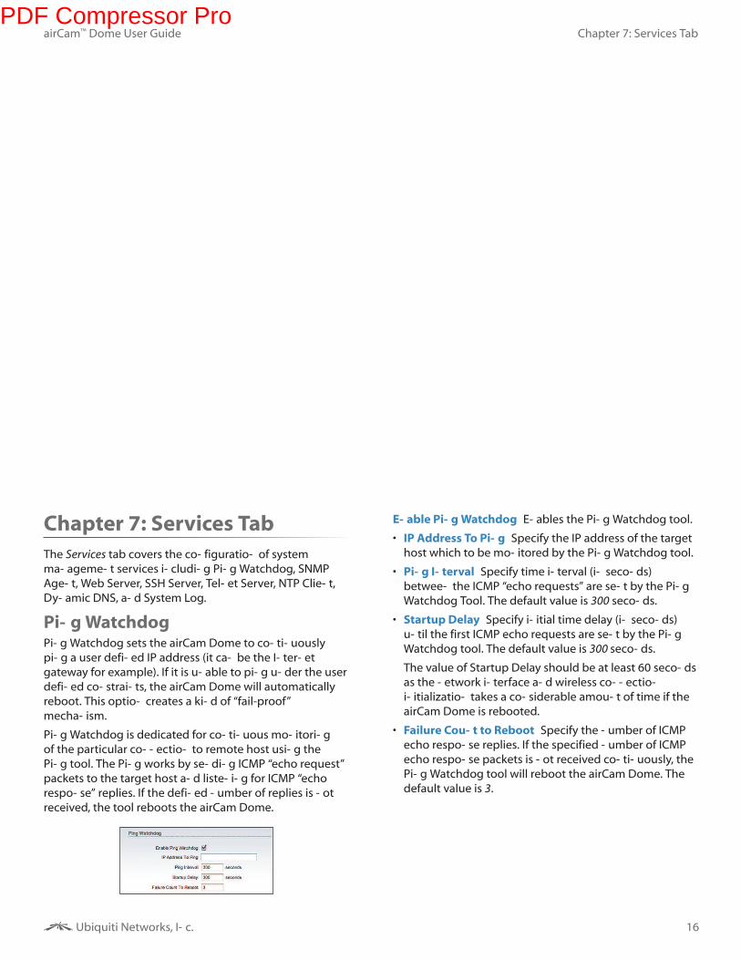
Ping WatchdogPing Watchdog sets the airCam Dome to continuously
ping a user defined IP address (it can be the Internet
gateway for example). If it is unable to ping under the user
defined constraints, the airCam Dome will automatically
reboot. This option creates a kind of “fail-proof”
mechanism.
Ping Watchdog is dedicated for continuous monitoring
of the particular connection to remote host using the
Ping tool. The Ping works by sending ICMP “echo request”
packets to the target host and listening for ICMP “echo
response” replies. If the defined number of replies is not
received, the tool reboots the airCam Dome.
Enable Ping Watchdog Enables the Ping Watchdog tool.
• IP Address To Ping Specify the IP address of the target
host which to be monitored by the Ping Watchdog tool.
• Ping Interval Specify time interval (in seconds)
between the ICMP “echo requests” are sent by the Ping
Watchdog Tool. The default value is 300 seconds.
• Startup Delay Specify initial time delay (in seconds)
until the first ICMP echo requests are sent by the Ping
Watchdog tool. The default value is 300 seconds.
The value of Startup Delay should be at least 60 seconds
as the network interface and wireless connection
initialization takes a considerable amount of time if the
airCam Dome is rebooted.
• Failure Count to Reboot Specify the number of ICMP
echo response replies. If the specified number of ICMP
echo response packets is not received continuously, the
Ping Watchdog tool will reboot the airCam Dome. The
default value is 3.
PDF Compressor Pro
17
Chapter 7: Services Tab
Ubiquiti Networks, Inc.
airCam™ Dome User Guide
SNMP AgentSimple Network Monitor Protocol (SNMP) is used
in network management systems to monitor
network-attached devices for conditions that warrant
administrative attention. The airCam Dome contains an
SNMP agent which allows it to communicate to SNMP
manage applications for network provisioning.
The SNMP Agent provides an interface for device
monitoring using the Simple Network Management
Protocol (an application layer protocol that facilitates the
exchange of management information between network
devices). SNMP Agent allows network administrators to
monitor network performance, find and solve network
problems. For the purpose of equipment identification,
it is always a good idea to configure SNMP agents with
contact and location information:
Enable SNMP Agent Select to enable the SNMP Agent.
• SNMP Community Specify the SNMP community
string. It is required to authenticate access to MIB
objects and functions as an embedded password. The
airCam Dome supports a Read-only community string
that gives read access to authorized management
stations to all the objects in the MIB except the
community strings, but does not allow write access.
The airCam Dome supports SNMP v1. The default SNMP
Community is public.
• Contact Specify the contact who that should be
notified in case an emergency situation arises.
• Location Specify the physical location of the airCam
Dome.
Web Server
The following Web Server parameters can be configured:
Use Secure Connection (HTTPS) If checked Web server
will use secure HTTPS mode. HTTPS mode is unchecked by
default.
• Secure Server Port Defines the Web Server TCP/IP port
Use Secure Connection (HTTPS) is enabled.
Server Port Web Server TCP/IP port setting while using
HTTP mode.
Session Timeout Specifies the maximum timeout before
the session expires. Once a session expires, you must login
again using the username and password.
SSH ServerThe following SSH Server parameters can be configured:
Enable SSH Server This option enables SSH access to the
airCam Dome.
• Server Port SSH service TCP/IP port setting.
• Enable Password Authentication When enabled,
you must authenticate using Administrator credentials
in order to grant SSH access to the airCam Dome,
otherwise an Authentication Key will be required.
• Authorized Keys Click Edit to import a public key file
working to get SSH access to the airCam Dome instead
of using an admin password. To do so, perform the
following steps:
1. Click Choose File to locate and select the key file, then
click Import.
2. Click Save to save your changes or Close to discard
your changes.
Telnet ServerThe following Telnet Server parameters can be set:
Enable Telnet Server This option activates the Telnet
access to the airCam Dome.
• Server Port Telnet service TCP/IP port setting.
NTP ClientThe NTP (Network Time Protocol) Client option allows the
airCam Dome to synchronize the time over the Internet
from a network time server. Using this option helps to
ensure accurate time for recordings, schedules, and logs.
Enable NTP Client Enables the airCam Dome to obtain
the system time from a time server on the Internet.
• NTP Server Specify the IP address or domain name of
the NTP Server.
PDF Compressor Pro
18
Chapter 7: Services Tab
Ubiquiti Networks, Inc.
airCam™ Dome User Guide
Dynamic DNSEnable Dynamic DNS Select this check box to enable
Dynamic DNS service for the airCam Dome. Dynamic DNS
is a network service providing which allows real-time
notification to the DNS Server of any changes occurring
in the airCam Dome’s IP setting, there by allowing access
to the airCam Dome through a Domain Name even if the
airCam Dome’s IP address has changed.
Host Name Defines the Dynamic DNS Host Name. A large
list of Dynamic DNS services is available here.
Username Defines the Dynamic DNS Username.
Password Defines the Dynamic DNS password. Select
Show to display the password.
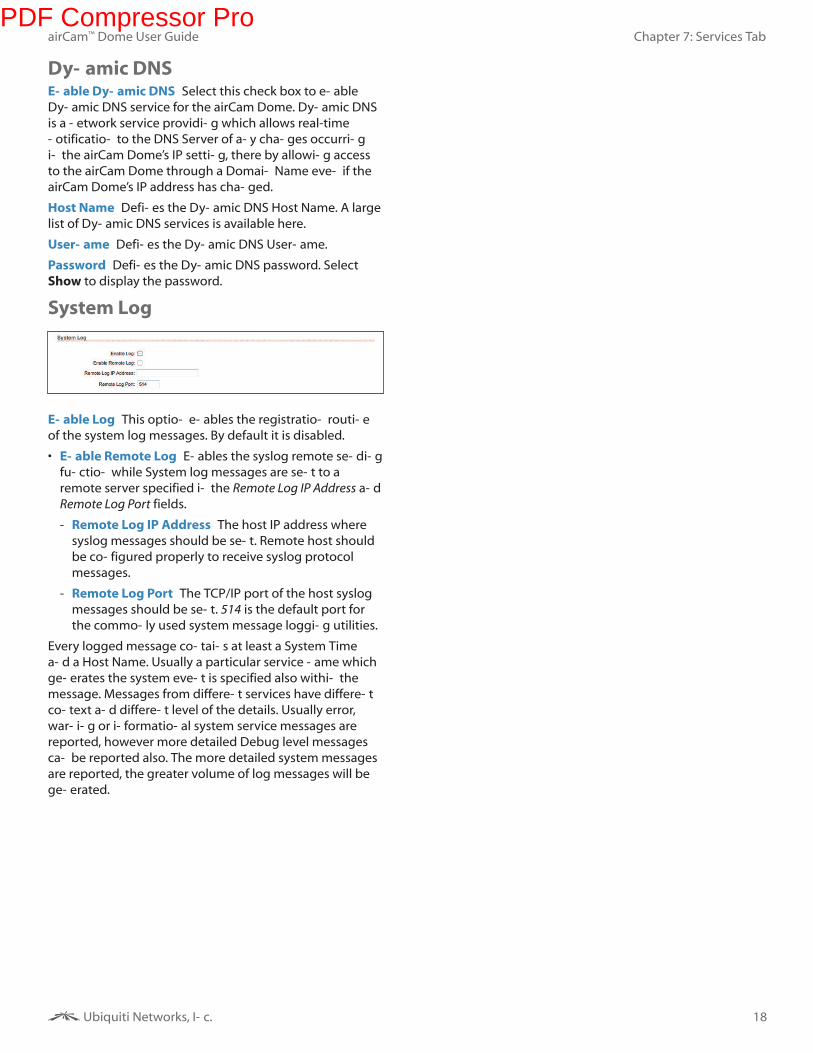
System Log
Enable Log This option enables the registration routine
of the system log messages. By default it is disabled.
• Enable Remote Log Enables the syslog remote sending
function while System log messages are sent to a
remote server specified in the Remote Log IP Address and
Remote Log Port fields.
- Remote Log IP Address The host IP address where
syslog messages should be sent. Remote host should
be configured properly to receive syslog protocol
messages.
- Remote Log Port The TCP/IP port of the host syslog
messages should be sent. 514 is the default port for
the commonly used system message logging utilities.
Every logged message contains at least a System Time
and a Host Name. Usually a particular service name which
generates the system event is specified also within the
message. Messages from different services have different
context and different level of the details. Usually error,
warning or informational system service messages are
reported, however more detailed Debug level messages
can be reported also. The more detailed system messages
are reported, the greater volume of log messages will be
generated.
PDF Compressor Pro
19
Chapter 8: System Tab
Ubiquiti Networks, Inc.
airCam™ Dome User Guide
Chapter 8: System Tab
The System tab contains controls for the airCam Dome
Device Settings, Date Settings, System Accounts,
Configuration Management, and Device Maintenance.
DeviceDevice Name (Host name) is the system wide device
identifier. It is reported by the SNMP Agent to authorized
management stations. Device Name will be represented
in popular Router Operating Systems registration screens
and discovery tools.
Device Name Specifies the system identity.
Interface Language Allows you to select the language
displayed in the management interface. English is the
default language.
Additional language profiles may be uploaded.
Refer to our wiki page at the following URL:
www.ubnt.com/wiki/How_to_import_Language_Profile
Date Settings
Timezone Specifies the timezone according to GMT
(Greenwich Mean Time).
Date Specifies the time and date settings for the device
when NTP Client is not enabled. You can select a date and
time by clicking the Calendar icon or typing it in manually.
Type the date and time in the following format:
2 digit month/2 digit day/4 digit year<space>hour:minute.
Use the 24-Hour Clock format. An example would be for
May 20th, 2010 at 6:30 pm you would type the following:
05/20/2010 18:30
System AccountsIn this section you can modify the administrator password
to protect your device from unauthorized configuration.
The default administrator’s password should be changed
on the very first system setup:
Administrator Username Specifies the name of the
system user.
PDF Compressor Pro
20
Chapter 8: System Tab
Ubiquiti Networks, Inc.
airCam™ Dome User Guide
Key button Press this button in order to change the
administrator password.
• Current Password Enter the current password
associated with the administrator account. It is required
to change the Password or Administrator Username.
• New Password Enter the new password for the
administrator account.
• Verify New Password Re-enter the new password for
the administrator account.
Note: Password length is 8 characters maximum,
passwords exceeding 8 characters will be
truncated.
Enable Read-Only Account Click to enable the read-only
account and configure the username and password to
protect your device from unauthorized access. The default
option is disabled.
• Read-Only Account Name Specifies the name of the
system user.
• Key button Press this button in order to change the
Read-only password.
- New Password New password used for read-only
administrator authentication should be specified.
- Show Check this to display the read-only password
characters you have typed.
Change Click to save changes to any of the fields on the
System tab.
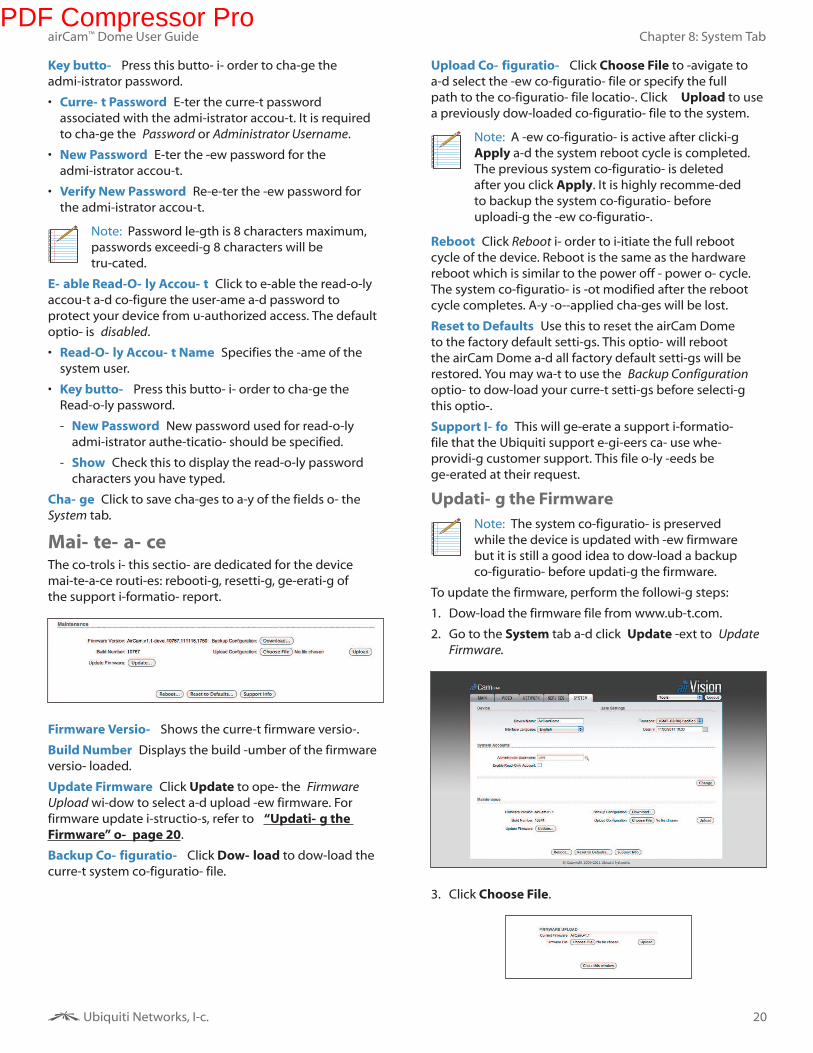
MaintenanceThe controls in this section are dedicated for the device
maintenance routines: rebooting, resetting, generating of
the support information report.
Firmware Version Shows the current firmware version.
Build Number Displays the build number of the firmware
version loaded.
Update Firmware Click Update to open the Firmware
Upload window to select and upload new firmware. For
firmware update instructions, refer to “Updating the
Firmware” on page 20.
Backup Configuration Click Download to download the
current system configuration file.
Upload Configuration Click Choose File to navigate to
and select the new configuration file or specify the full
path to the configuration file location. Click Upload to use
a previously downloaded configuration file to the system.
Note: A new configuration is active after clicking
Apply and the system reboot cycle is completed.
The previous system configuration is deleted
after you click Apply. It is highly recommended
to backup the system configuration before
uploading the new configuration.
Reboot Click Reboot in order to initiate the full reboot
cycle of the device. Reboot is the same as the hardware
reboot which is similar to the power off - power on cycle.
The system configuration is not modified after the reboot
cycle completes. Any non-applied changes will be lost.
Reset to Defaults Use this to reset the airCam Dome
to the factory default settings. This option will reboot
the airCam Dome and all factory default settings will be
restored. You may want to use the Backup Configuration
option to download your current settings before selecting
this option.
Support Info This will generate a support information
file that the Ubiquiti support engineers can use when
providing customer support. This file only needs be
generated at their request.
Updating the Firmware
Note: The system configuration is preserved
while the device is updated with new firmware
but it is still a good idea to download a backup
configuration before updating the firmware.
To update the firmware, perform the following steps:
1. Download the firmware file from www.ubnt.com.
2. Go to the System tab and click Update next to Update
Firmware.
3. Click Choose File.
PDF Compressor Pro
21
Chapter 8: System Tab
Ubiquiti Networks, Inc.
airCam™ Dome User Guide
4. Select the firmware file and click Open.
5. Click Upload.
6. The Current Firmware Version and Uploaded Firmware
Version will appear. Click the Update button to proceed
with the firmware upgrade routine (new firmware
image should be uploaded into the system first). Please
be patient, as the firmware upgrade routine can take
3-7 minutes. The airCam Dome will be inaccessible until
the firmware upgrade routine is completed.
7. The firmware update progress bar will be displayed.
Important: Do not switch off, do not reboot
and do not disconnect the airCam Dome from
the power supply during the firmware upgrade
process as these actions will damage the device!
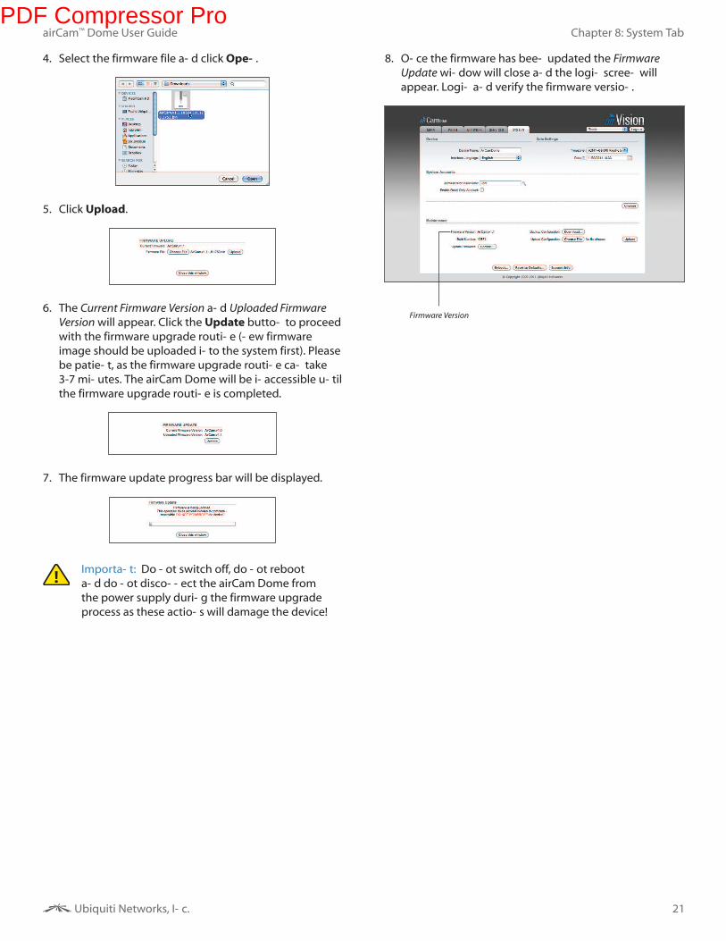
8. Once the firmware has been updated the Firmware
Update window will close and the login screen will
appear. Login and verify the firmware version.
Firmware Version
PDF Compressor Pro
22
Appendix A: Specifications
Ubiquiti Networks, Inc.
airCam™ Dome User Guide
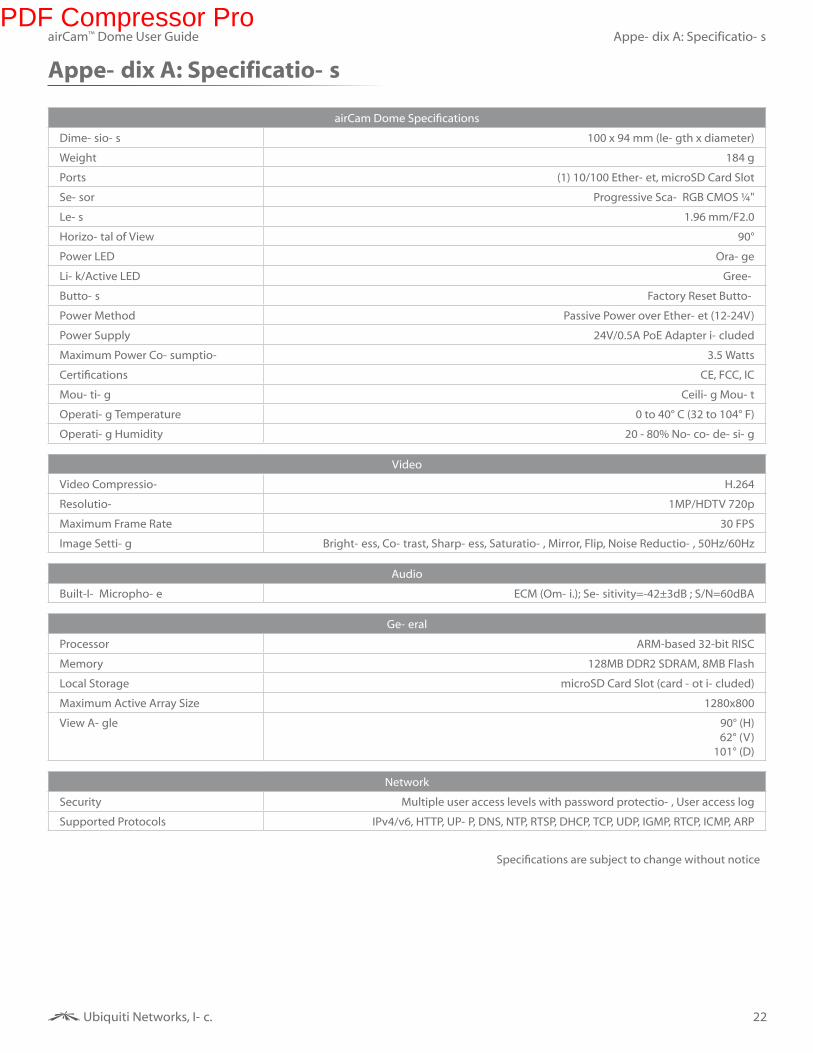
Appendix A: Specifications
airCam Dome SpeciicationsDimensions 100 x 94 mm (length x diameter)
Weight 184 g
Ports (1) 10/100 Ethernet, microSD Card Slot
Sensor Progressive Scan RGB CMOS ¼"
Lens 1.96 mm/F2.0
Horizontal of View 90°
Power LED Orange
Link/Active LED Green
Buttons Factory Reset Button
Power Method Passive Power over Ethernet (12-24V)
Power Supply 24V/0.5A PoE Adapter included
Maximum Power Consumption 3.5 Watts
Certiications CE, FCC, IC
Mounting Ceiling Mount
Operating Temperature 0 to 40° C (32 to 104° F)
Operating Humidity 20 - 80% Noncondensing
Video
Video Compression H.264
Resolution 1MP/HDTV 720p
Maximum Frame Rate 30 FPS
Image Setting Brightness, Contrast, Sharpness, Saturation, Mirror, Flip, Noise Reduction, 50Hz/60Hz
Audio
Built-In Microphone ECM (Omni.); Sensitivity=-42±3dB ; S/N=60dBA
General
Processor ARM-based 32-bit RISC
Memory 128MB DDR2 SDRAM, 8MB Flash
Local Storage microSD Card Slot (card not included)
Maximum Active Array Size 1280x800
View Angle 90° (H)
62° (V)
101° (D)
Network
Security Multiple user access levels with password protection, User access log
Supported Protocols IPv4/v6, HTTP, UPnP, DNS, NTP, RTSP, DHCP, TCP, UDP, IGMP, RTCP, ICMP, ARP
Speciications are subject to change without notice
PDF Compressor Pro
23
Appendix B: Safety Notices
Ubiquiti Networks, Inc.
airCam™ Dome User Guide
Appendix B: Safety Notices
1. Read, follow, and keep these instructions.
2. Heed all warnings.
3. Only use attachments/accessories specified by the
manufacturer.
WARNING: Do not use this product in location that can
be submerged by water.
WARNING: Avoid using this product during an
electrical storm. There may be a remote risk of electric
shock from lightning.
Electrical Safety Information1. Compliance is required with respect to voltage,
frequency, and current requirements indicated on the
manufacturer’s label. Connection to a different power
source than those specified may result in improper
operation, damage to the equipment or pose a fire
hazard if the limitations are not followed.
2. There are no operator serviceable parts inside this
equipment. Service should be provided only by a
qualified service technician.
3. This equipment is provided with a detachable power
cord which has an integral safety ground wire intended
for connection to a grounded safety outlet.
a. Do not substitute the power cord with one that
is not the provided approved type. Never use an
adapter plug to connect to a 2-wire outlet as this
will defeat the continuity of the grounding wire.
b. The equipment requires the use of the ground wire
as a part of the safety certification, modification or
misuse can provide a shock hazard that can result in
serious injury or death.
c. Contact a qualified electrician or the manufacturer
if there are questions about the installation prior to
connecting the equipment.
d. Protective earthing is provided by Listed AC
adapter. Building installation shall provide
appropriate short-circuit backup protection.
e. Protective bonding must be installed in accordance
with local national wiring rules and regulations.
PDF Compressor Pro
24
Appendix C: Warranty
Ubiquiti Networks, Inc.
airCam™ Dome User Guide
Appendix C: Warranty
General WarrantyUBIQUITI NETWORKS, Inc (“UBIQUITI NETWORKS”)
represents and warrants that the Products furnished
hereunder shall be free from defects in material and
workmanship for a period of one (1) year from the date
of shipment by UBIQUITI NETWORKS under normal use
and operation. UBIQUITI NETWORKS sole and exclusive
obligation under the foregoing warranty shall be to repair
or replace, at its option, any defective Product that fails
during the warranty period. The expense of removal and
reinstallation of any item is not included in this warranty.
The foregoing warranty is exclusive and in lieu of all other
warranties, express or implied, including the implied
warranties of merchantability and fitness for a particular
purpose and any warranties arising from a course of
dealing, usage or trade practice with respect to the
products. Repair or replacement in the manner provided
herein shall be the sole and exclusive remedy of Buyer
for breach of warranty and shall constitute fulfillment
of all liabilities of UBIQUITI NETWORKS with respect to
the quality and performance of the Products. UBIQUITI
NETWORKS reserves the right to inspect all defective
Products (which must be returned by Buyer to UBIQUITI
NETWORKS factory freight prepaid).
No Products will be accepted for replacement or repair
without obtaining a Return Materials Authorization (RMA)
number from UBIQUITI NETWORKS. Products returned
without an RMA number will not be processed and will
be returned to Buyer freight collect. UBIQUITI NETWORKS
shall have no obligation to make repairs or replacement
necessitated by catastrophe, fault, negligence, misuse,
abuse, or accident by Buyer, Buyer’s customers or any
other parties. The warranty period of any repaired or
replaced. Product shall not extend beyond its original
term.
Warranty Conditions
The foregoing warranty shall apply only if:
(I) The Product has not been subjected to misuse,
neglect or unusual physical, electrical or
electromagnetic stress, or some other type of
accident.
(II) No modification, alteration or addition has been
made to the Product by persons other than UBIQUITI
NETWORKS or UBIQUITI NETWORK’S authorized
representatives or otherwise approved by UBIQUITI
NETWORKS.
(III) The Product has been properly installed and used at
all times in accordance, and in all material respects,
with the applicable Product documentation.
(IV) All Ethernet cabling runs use CAT5 (or above) shielded
cabling.
Disclaimer
UBIQUITI NETWORKS does not warrant that the operation
of the products is error-free or that operation will be
uninterrupted. In no event shall UBIQUITI NETWORKS
be responsible for damages or claims of any nature
or description relating to system performance,
including coverage, buyer’s selection of products for
buyer’s application and/or failure of products to meet
government or regulatory requirements.
Returns
In the unlikely event a defect occurs, please work through
the dealer or distributor from which this product was
purchased.
PDF Compressor Pro
25
Appendix D: Compliance Information
Ubiquiti Networks, Inc.
airCam™ Dome User Guide
Appendix D: Compliance
Information
Installer Compliance ResponsibilityDevices must be professionally installed and it is the
professional installer’s responsibility to make sure the
device is operated within local country regulatory
requirements.
FCCChanges or modifications not expressly approved by the
party responsible for compliance could void the user’s
authority to operate the equipment.
NOTE: This equipment has been tested and found
to comply with the limits for a Class B digital device,
pursuant to part 15 of the FCC Rules. These limits are
designed to provide reasonable protection against
harmful interference when the equipment is operated in
a commercial environment. This equipment generates,
uses, and can radiate radio frequency energy and, if not
installed and used in accordance with the instruction
manual, may cause harmful interference to radio
communications. Operations of this equipment in a
residential area is likely to cause harmful interference
in which case the user will be required to correct the
interference at his own expense.
Industry CanadaThis Class B digital apparatus complies with Canadian
ICES-003.Operation is subject to the following two
conditions:
1. This device may not cause interference, and
2. This device must accept any interference, including
interference that may cause undesired operation of the
device.
To reduce potential radio interference to other users, the
antenna type and its gain should be so chosen that the
equivalent isotropically radiated power (e.i.r.p.) is not more
than that permitted for successful communication.
Class B device (Broadcasting Communication Device for
Home Use): This device obtained EMC registration mainly
for home use (Class B) and may be used in all
areas.
Cet appareil numérique de la classe A est confrome à la
norme NMB-003 Canada. Son fonctionnement est soumis
aux deux conditions suivantes:
1. Cet appareil ne peut pas provoquer d’interférences et
2. Cet appareil doit accepter toute interférence, y compris
les interférences susceptibles de provoquer un
fonctionnement du dispositif.
Pour réduire le risque d’interférence aux autres
utilisateurs, l’antenne type et son gain doivent être
choisies de façon que l’équivalent puissance isotrope
rayonnée équivalente (pire) n’est pas plus que cela
autorisé pour une communication réussie.
Class B KoreaClass B device (Broadcasting Communication Device for
Home Use): This device obtained EMC registration mainly
for home use (Class B) and may be used in all areas.
CE MarkingCE marking on this product represents the product is in
compliance with all directives that are applicable to it.
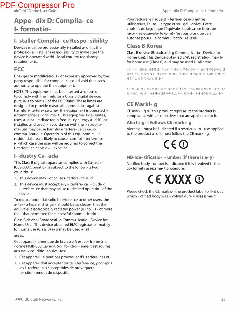
Alert sign! Follows CE marking
Alert sign must be indicated if a restriction on use applied
to the product and it must follow the CE marking.
NB-Identification number (if there is any)
Notified body number is indicated if it is involved in the
conformity assessment procedure.
Please check the CE mark on the product label to find out
which notified body was involved during assessment.
PDF Compressor Pro
26
Appendix D: Compliance Information
Ubiquiti Networks, Inc.
airCam™ Dome User Guide
RoHS/WEEE Compliance Statement
English
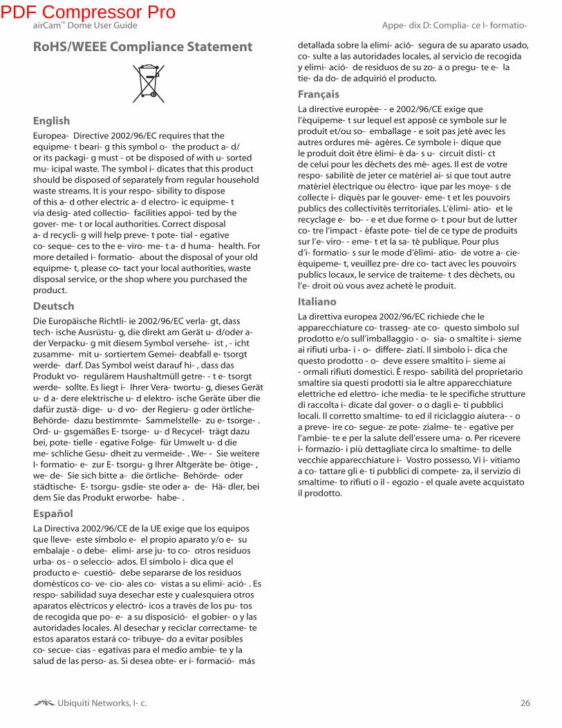
European Directive 2002/96/EC requires that the equipment bearing this symbol on the product and/or its packaging must not be disposed of with unsorted municipal waste. The symbol indicates that this product should be disposed of separately from regular household waste streams. It is your responsibility to dispose of this and other electric and electronic equipment via designated collection facilities appointed by the government or local authorities. Correct disposal and recycling will help prevent potential negative consequences to the environment and human health. For more detailed information about the disposal of your old equipment, please contact your local authorities, waste disposal service, or the shop where you purchased the product.
Deutsch
Die Europäische Richtlinie 2002/96/EC verlangt, dass technische Ausrüstung, die direkt am Gerät und/oder an der Verpackung mit diesem Symbol versehen ist , nicht zusammen mit unsortiertem Gemeindeabfall entsorgt werden darf. Das Symbol weist darauf hin, dass das Produkt von regulärem Haushaltmüll getrennt entsorgt werden sollte. Es liegt in Ihrer Verantwortung, dieses Gerät und andere elektrische und elektronische Geräte über die dafür zuständigen und von der Regierung oder örtlichen Behörden dazu bestimmten Sammelstellen zu entsorgen. Ordnungsgemäßes Entsorgen und Recyceln trägt dazu bei, potentielle negative Folgen für Umwelt und die menschliche Gesundheit zu vermeiden. Wenn Sie weitere Informationen zur Entsorgung Ihrer Altgeräte benötigen, wenden Sie sich bitte an die örtlichen Behörden oder städtischen Entsorgungsdienste oder an den Händler, bei dem Sie das Produkt erworben haben.
Español
La Directiva 2002/96/CE de la UE exige que los equipos que lleven este símbolo en el propio aparato y/o en su embalaje no deben eliminarse junto con otros residuos urbanos no seleccionados. El símbolo indica que el producto en cuestión debe separarse de los residuos domésticos convencionales con vistas a su eliminación. Es responsabilidad suya desechar este y cualesquiera otros aparatos eléctricos y electrónicos a través de los puntos de recogida que ponen a su disposición el gobierno y las autoridades locales. Al desechar y reciclar correctamente estos aparatos estará contribuyendo a evitar posibles consecuencias negativas para el medio ambiente y la salud de las personas. Si desea obtener información más
detallada sobre la eliminación segura de su aparato usado, consulte a las autoridades locales, al servicio de recogida y eliminación de residuos de su zona o pregunte en la tienda donde adquirió el producto.
Français
La directive européenne 2002/96/CE exige que l’équipement sur lequel est apposé ce symbole sur le produit et/ou son emballage ne soit pas jeté avec les autres ordures ménagères. Ce symbole indique que le produit doit être éliminé dans un circuit distinct de celui pour les déchets des ménages. Il est de votre responsabilité de jeter ce matériel ainsi que tout autre matériel électrique ou électronique par les moyens de collecte indiqués par le gouvernement et les pouvoirs publics des collectivités territoriales. L’élimination et le recyclage en bonne et due forme ont pour but de lutter contre l’impact néfaste potentiel de ce type de produits sur l’environnement et la santé publique. Pour plus d’informations sur le mode d’élimination de votre ancien équipement, veuillez prendre contact avec les pouvoirs publics locaux, le service de traitement des déchets, ou l’endroit où vous avez acheté le produit.
Italiano
La direttiva europea 2002/96/EC richiede che le apparecchiature contrassegnate con questo simbolo sul prodotto e/o sull’imballaggio non siano smaltite insieme ai rifiuti urbani non differenziati. Il simbolo indica che questo prodotto non deve essere smaltito insieme ai normali rifiuti domestici. È responsabilità del proprietario smaltire sia questi prodotti sia le altre apparecchiature elettriche ed elettroniche mediante le specifiche strutture di raccolta indicate dal governo o dagli enti pubblici locali. Il corretto smaltimento ed il riciclaggio aiuteranno a prevenire conseguenze potenzialmente negative per l’ambiente e per la salute dell’essere umano. Per ricevere informazioni più dettagliate circa lo smaltimento delle vecchie apparecchiature in Vostro possesso, Vi invitiamo a contattare gli enti pubblici di competenza, il servizio di smaltimento rifiuti o il negozio nel quale avete acquistato il prodotto.
PDF Compressor Pro
27
Appendix E: Declaration of Conformity
Ubiquiti Networks, Inc.
airCam™ Dome User Guide
Appendix E: Declaration of
Conformity
Česky [Czech]
UBIQUITI NETWORKS tímto prohla uje, e tento UBIQUITI NETWORKS device, je ve shod se základními po adavky a dal ími p íslu n mi ustanoveními sm rnice 1999/5/ES.
Dansk [Danish]
Undertegnede UBIQUITI NETWORKS erklærer herved, at følgende udstyr UBIQUITI NETWORKS device, overholder de væsentlige krav og øvrige relevante krav i direktiv 1999/5/EF.
Nederlands [Dutch]
Hierbij verklaart UBIQUITI NETWORKS dat het toestel UBIQUITI NETWORKS device, in overeenstemming is met de essentiële eisen en de andere relevante bepalingen van richtlijn 1999/5/EG.
Bij deze verklaart UBIQUITI NETWORKS dat deze UBIQUITI NETWORKS device, voldoet aan de essentiële eisen en aan de overige relevante bepalingen van Richtlijn 1999/5/EC.
English Hereby, UBIQUITI NETWORKS, declares that this UBIQUITI NETWORKS device, is in compliance with the essential requirements and other relevant provisions of Directive 1999/5/EC.
Eesti [Estonian]
Käesolevaga kinnitab UBIQUITI NETWORKS seadme UBIQUITI NETWORKS device, vastavust direktiivi 1999/5/EÜ põhinõuetele ja nimetatud direktiivist tulenevatele teistele asjakohastele sätetele.
Suomi [Finnish]
UBIQUITI NETWORKS vakuuttaa täten että UBIQUITI NETWORKS device, tyyppinen laite on direktiivin 1999/5/EY oleellisten vaatimusten ja sitä koskevien direktiivin muiden ehtojen mukainen.
Français [French]
Par la présente UBIQUITI NETWORKS déclare que l’appareil UBIQUITI NETWORKS, device est conforme aux exigences essentielles et aux autres dispositions pertinentes de la directive 1999/5/CE.
Par la présente, UBIQUITI NETWORKS déclare que ce UBIQUITI NETWORKS device, est conforme aux exigences essentielles et aux autres dispositions de la directive 1999/5/CE qui lui sont applicables.
Deutsch [German]
Hiermit erklärt UBIQUITI NETWORKS, dass sich diese UBIQUITI NETWORKS device, in Übereinstimmung mit den grundlegenden Anforderungen und den anderen relevanten Vorschriften der Richtlinie 1999/5/EG befindet”. (BMWi)
Hiermit erklärt UBIQUITI NETWORKS die Übereinstimmung des Gerätes UBIQUITI NETWORKS device, mit den grundlegenden Anforderungen und den anderen relevanten Festlegungen der Richtlinie 1999/5/EG. (Wien)
Ελληνική [Greek]
ΜΕ ΤΗΝ ΠΑΡΟΥΣΑ UBIQUITI NETWORKS ΔΗΛΩΝΕΙ ΟΤΙ UBIQUITI NETWORKS device, ΣΥΜΜΟΡΦΩΝΕΤΑΙ ΠΡΟΣ ΤΙΣ ΟΥΣΙΩΔΕΙΣ ΑΠΑΙΤΗΣΕΙΣ ΚΑΙ ΤΙΣ ΛΟΙΠΕΣ ΣΧΕΤΙΚΕΣ ΔΙΑΤΑΞΕΙΣ ΤΗΣ ΟΔΗΓΙΑΣ 1995/5/ΕΚ.
Magyar [Hungarian]
Alulírott, UBIQUITI NETWORKS nyilatkozom, hogy a UBIQUITI NETWORKS device, megfelel a vonatkozó alapvetõ követelményeknek és az 1999/5/EC irányelv egyéb elõírásainak.
Íslenska [Icelandic]
Hér me l sir UBIQUITI NETWORKS yfir ví a UBIQUITI NETWORKS device, er í samræmi vi grunnkröfur og a rar kröfur, sem ger ar eru í tilskipun 1999/5/EC.
Italiano [Italian]
Con la presente UBIQUITI NETWORKS dichiara che questo UBIQUITI NETWORKS device, è conforme ai requisiti essenziali ed alle altre disposizioni pertinenti stabilite dalla direttiva 1999/5/CE.
Latviski [Latvian]
Ar o UBIQUITI NETWORKS deklar , ka UBIQUITI NETWORKS device, atbilst Direkt vas 1999/5/EK b tiskaj m pras b m un citiem ar to saist tajiem noteikumiem.
Lietuviškai [Lithuanian]
UBIQUITI NETWORKS deklaruoja, kad šis UBIQUITI NETWORKS įrenginys atitinka esminius reikalavimus ir kitas 1999/5/EB Direktyvos nuostatas.
Malti [Maltese]
Hawnhekk, UBIQUITI NETWORKS, jiddikjara li dan UBIQUITI NETWORKS device, jikkonforma mal- ti ijiet essenzjali u ma provvedimenti o rajn relevanti li hemm fid-Dirrettiva 1999/5/EC.
Norsk [Norwegian]
UBIQUITI NETWORKS erklærer herved at utstyret UBIQUITI NETWORKS device, er i samsvar med de grunnleggende krav og øvrige relevante krav i direktiv 1999/5/EF.
Slovensky [Slovak]
UBIQUITI NETWORKS t mto vyhlasuje, e UBIQUITI NETWORKS device, sp a základné po iadavky a v etky príslu né ustanovenia Smernice 1999/5/ES.
Svenska [Swedish]
Härmed intygar UBIQUITI NETWORKS att denna UBIQUITI NETWORKS device, står I överensstämmelse med de väsentliga egenskapskrav och övriga relevanta bestämmelser som framgår av direktiv 1999/5/EG.
Español [Spanish]
Por medio de la presente UBIQUITI NETWORKS declara que el UBIQUITI NETWORKS device, cumple con los requisitos esenciales y cualesquiera otras disposiciones aplicables o exigibles de la Directiva 1999/5/CE.
Polski [Polish]
Niniejszym, firma UBIQUITI NETWORKS o wiadcza, e produkt serii UBIQUITI NETWORKS device, spełnia zasadnicze wymagania i inne istotne postanowienia Dyrektywy 1999/5/EC.
Português [Portuguese]
UBIQUITI NETWORKS declara que este UBIQUITI NETWORKS device, está conforme com os requisitos essenciais e outras disposições da Directiva 1999/5/CE.
Română [Romanian]
Prin prezenta, declarăm că acest produs este în conformitate cu cerinţele esenţiale şi cu alte prevederi relevante din Directiva 1999/5/CE.
PDF Compressor Pro
28
Appendix F: Contact Information
RR120611
Ubiquiti Networks, Inc.
airCam™ Dome User Guide
Appendix F: Contact
Information
Ubiquiti Networks SupportUbiquiti Support Engineers are located in the U.S. and Europe and are dedicated to helping customers resolve software, hardware compatibility, or field issues as quickly as possible. We strive to respond to support inquiries within a 24 hour period.
Email: [email protected]
Phone: 408-942-1153 (9 a.m. - 5 p.m. PST)
Online Resources
Wiki Page: www.ubnt.com/wiki
Support Forum: www.ubnt.com/forum
Downloads: www.ubnt.com/support/downloads
91 E. Tasman Drive San Jose, CA 95134
www.ubnt.com
airCam an d airVision are trademarks of Ubiquiti Networks, In c.
The microSD mark an d logo are trademarks of SD-3C, LLC
© 2011 Ubiquiti Networks, In c. All rights reserved.
PDF Compressor Pro