Embed Size (px)
Citation preview

Snap-through transition of graphene membranes formemcapacitor applications: A combined studyusing MD, DFT and elasticity theoryRuslan D. Yamaletdinov1,2,*, Oleg V. Ivakhnenko3,4, Olga V. Sedelnikova1,2,Sergey N. Shevchenko3,4, and Yuriy V. Pershin1,5,†
1Nikolaev Institute of Inorganic Chemistry SB RAS, Novosibirsk 630090, Russia2Novosibirsk State University, Novosibirsk 630090, Russia3B. I. Verkin Institute for Low Temperature Physics and Engineering, Kharkov 61103, Ukraine4V. N. Karazin Kharkov National University, Kharkov 61022, Ukraine5Department of Physics and Astronomy, University of South Carolina, Columbia, South Carolina 29208, USA*[email protected]†[email protected]
ABSTRACT
Using computational and theoretical approaches, we investigate the snap-through transition of buckled graphene membranes.Our main interest is related to the possibility of using the buckled membrane as a plate of capacitor with memory (memcapacitor).For this purpose, we performed molecular-dynamics (MD) simulations and elasticity theory calculations of the up-to-down anddown-to-up snap-through transitions for membranes of several sizes. We have obtained expressions for the threshold switchingforces for both up-to-down and down-to-up transitions. Moreover, the up-to-down threshold switching force was calculatedusing the density functional theory (DFT). Our DFT results are in general agreement with MD and analytical theory findings.Our systematic approach can be used for the description of other structures, including nanomechanical and biological ones,experiencing the snap-through transition.
Introduction
Memcapacitors1 are an emerging type of circuit elements with memory whose instantaneous response depends on the internalstate and input signal. Such devices are prospective candidates for applications in information storage and processing2, 3
technologies as their states can be manipulated by the applied voltages or charges and can store information for long intervalsof time. Several possible realizations of memcapacitors were suggested by using micro-electro-mechanical systems4, ionictransport5, electronic effects6, superconducting qubits7, etc.8
Generally, voltage-controlled memcapacitive systems (memcapacitors) are described by1
q(t) = C (x,V, t)V (t), (1)x = f (x,V, t) , (2)
where q(t) is the charge on the capacitor at time t, V (t) is the applied voltage, C is the memcapacitance (memory capacitance),x is a set of n internal state variables, and f is a continuous n-dimensional vector function. In some cases, it is more convenientto consider charge-controlled memcapacitors1 such that the charge instead of voltage is considered as input.
Among several possible realizations of memcapacitors, the membrane-based memcapacitors4 are of significant interestas their geometry makes them intrinsically suitable for non-volatile storage of binary information. Indeed, the buckledmembrane used as the top capacitor plate (see Fig. 1 for schematics) has two stable buckled states corresponding to twodistinct values of capacitance. It was suggested4 that the switching between these states can be performed using the attractiveinteraction of oppositely charged capacitor plates. Moreover, it was demonstrated theoretically that simple circuits of membranememcapacitors offer an in-memory computing functionality3.
In this work, we consider a possible realization of membrane-based memcapacitor4 employing a single- or multi-layergraphene membrane9–13 as its bistable plate (see Fig. 1). Our aim is to understand the basic physical processes and parametersunderlying the snap-through transition of such membrane including details of the membrane dynamics, threshold forces, etc.For this purpose, we perform a combined study using MD, DFT and elasticity theory focusing on a single-layer graphenemembrane with clamped boundary conditions. This choice of boundary conditions is justified by the typically strong adhesion
arX
iv:1
707.
0763
9v2
[co
nd-m
at.m
es-h
all]
25
Dec
201
7

of graphene to substrates. Our results extend our prior DFT investigation14 of the up-to-down snap-through transition ofgraphene membrane with hinged boundary conditions.
The combination of computational/theoretical methods adds breadth and depth to our analysis. Using MD simulations,we were able to understand main features of the membrane dynamics in the presence of an external force and after the forceremoval. This understanding has helped us to develop analytical models that resulted in compact algebraic expressions for thethreshold switching forces. DFT calculations were used to validate MD results for the up-to-down transition.
This paper is organized as follows. In Sec. ”Molecular Dynamics Simulations” we investigate the snap-through transition ofgraphene membranes using molecular dynamics simulations. In particular, MD simulations of the up-to-down and down-to-uptransitions are reported in Subsec. ”Up-to-down transition” and ”Down-to-up transition”, respectively, while MD simulationdetails can be found in Supplementary Information (SI) Sec. ”MD Simulation details”. The standard elasticity theory is appliedto the membrane switching in Subsec. ”Buckling and snapping-through within the theory of elasticity”. A phenomenologicalanalytical model of the snap-through transition is presented in Subsec. ”Phenomenological elasticity theory” and in SI Sec.”Phenomenological Elasticity Theory”. Our DFT calculations are summarized in Sec. ”Density Functional Theory”. The resultsobtained within different approaches as well as their implications are discussed in Sec. ”Discussion”.
In this paper, the following notations are used:
q - the charge on capacitor (see Eq. (1))V - the applied voltage (see Eqs. (1), (2))C - the (memory) capacitance (see Eq. (1))d - the distance between fixed sides of membrane (see Fig. 1)h - the distance between the bottom plate and the level of fixed sides (see Fig. 1)L - the membrane lengthw - the membrane widthD = 1.6 eV - the bending rigidity of grapheneE2D = 340 N/m - the 2D Young’s moduleζ - the deflection of membrane (see Eq. (3))ζc - the maximum deflection of membrane (see Eq. (7))θi(s) - the angle that the membrane makes with the horizontal (see Eqs. (16) and (17)),s - the internal coordinate that changes between −1/2 and 1/2 (see Eqs. (16) and (17))Ai and ci - coefficients (see Eqs. (16) and (17))zcm - the center of mass position (see Eq. (19))Ub, Ustr, Uext - the bending, stretching and external potential contributions to the potential energy of membrane (see Eq. (18))F↓ - the up-to-down threshold switching force (see Eqs. (12), (20), (21), and (22))F↑ - the down-to-up threshold switching force (see Eqs. (14) and (28))ε0 - the vacuum permittivity
Molecular Dynamics Simulations
MD simulations are a well established modeling tool frequently employed in studies of nanoscale carbon-based materials15–36.We used classical MD simulations to investigate the dynamics of snap-through transition of buckled graphene membranes.Zigzag graphene nanoribbons (membranes) of two lengths were considered: the nanoribbon A, L = 54 A (22 rings), andnanoribbon B, L = 103 A (42 rings). Both nanoribbons were of the same width (w = 41 A). In order to implement the clampedboundary conditions, the first two lines of carbon atoms at shorter sides were kept fixed. The buckling was realized by changing
Figure 1. Schematics of the membrane memcapacitor employing a buckled graphene membrane as its top plate4.
2/22

(a)
z ct f
d/Ld/Ld/Ld/Ld/L
(b)
z ct f
d/Ld/Ld/Ld/Ld/L
Figure 2. Up-to-down transition: the final position (at a time t f ) of a central atom of membrane as a function of the appliedforce magnitude for (a) shorter membrane A (22 rings length), and (b) longer membrane B (42 rings length). The calculationdetails are given in the text.
the distance between the fixed sides from L to d < L. The same external force was applied to each atom in the downwarddirection to simulate the attractive interaction between the plates.
See SI Sec. ”MD Simulation details” for the details of MD simulations.
Up-to-down transitionIn order to simulate the up-to-down transition, the double-clamped graphene nanoribbon buckled upwards was subjected to theforce in the downward direction. The final state of membrane was found using MD simulations as described in SI Sec. ”MDSimulation details”. Figure 2 shows the final position of a central atom of membrane versus the applied force for several valuesof d/L and two membrane sizes. According to Fig. 2, at fixed L, the up-to-down threshold switching force (the minimal forcerequired for the up-to-down transition) is larger for smaller values of d/L. Moreover, at fixed d/L, the threshold switchingforce is smaller for longer membranes. Additionally, some curves in Fig. 2 exhibit a noisy threshold (such as d/L = 0.8 andd/L = 0.98 in (a)), which can be related to thermal fluctuations of membranes. All these observations are intuitively reasonable.
(a) (b)
Figure 3. Geometries of membrane B in the process of the up-to-down switching at smaller (F = 0.5 pN/atom) (a) and larger(F = 1.49 pN/atom) (b) forces. These geometries were obtained using overdamped MD simulations for d/L = 0.95 (thesimulation parameters are provided in the Supplementary Information). The switching occurs through the non-symmetric pathat smaller forces (exceeding the threshold) (a), and symmetric path at larger forces (b).
Depending on the force magnitude, the membrane switching occurs either through the symmetric or non-symmetric
3/22

(a)
d/L d/L d/Ld/L d/L
z ct f
(b)
z ct f
d/L d/L d/Ld/L d/L
Figure 4. Down-to-up transition: the final position of a central atom of membrane as a function of the applied forcemagnitude for (a) shorter membrane A (22 rings length), and (b) longer membrane B (42 rings length).
membrane profile (see Fig. 3). Figure 3 was obtained using overdamped simulations of membrane dynamics (additionalresults of these simulations can be found in SI Sec. ”MD Simulation details”). The non-symmetric profile is associated with asmaller energy barrier14 and involved in switching by smaller forces. Larger applied forces result in the switching throughthe symmetric profile. According to our observations and previous work14, in all cases, the membrane profile is symmetric atshort times. If the force magnitude is sufficient to overcome the energy barrier for the symmetric profile, then, typically, theswitching takes place through the symmetric path. Otherwise, a symmetry breaking occurs leading to the switching through thelower energy barrier associated with the non-symmetric membrane profile. Thermal fluctuations help the symmetry breaking.
Down-to-up transitionIt was suggested in Ref. 4 that the memcapacitor membrane can be set into the buckled upwards state 0 (see Fig. 1) by alsousing the electrostatic attraction between the capacitor plates. When the pulled-down membrane is suddenly released, there areconditions such that the membrane overcomes the potential barrier and ends up in the buckled upwards state. As the kineticenergy plays an important role in the down-to-up transition, this process can not be analyzed using the overdamped dynamics.
In order to simulate the down-to-up transition, every atom of a double-clamped buckled membrane was subjected to aconstant force in -z direction. After an equilibration period, the forces were removed, and the system was simulated for a timeinterval sufficient to reach the steady state. The final position of a central atom of membrane is presented in Fig. 4 as a functionof the applied force for several values of d/L.
Figure 4 shows that the threshold forces for the down-to-up transition are larger than those for the up-to-down transition(see Fig. 2). Moreover, the threshold forces for the down-to-up transition are larger for the shorter membrane A comparedto the longer membrane B. It is interesting that the final state of membrane oscillates as a function of the applied force (seed/L = 0.98 curves in Fig. 4). Qualitatively, having a high kinetic energy, the membrane moves up and down while its energydissipates. Finally, it gets trapped in one of two stable buckled states.
Overall, our MD results indicate the possibility of writing one bit of information into the state of membrane memcapacitor.In this interpretation, logic 1 corresponds to the membrane buckled downwards, and logic 0 - to the membrane buckled upwards.In addition to 0→ 1 and 1→ 0 transitions presented in Figs. 2 and 4, we have verified the occurrence of 1→ 1 and 0→ 0transitions at the same values of forces required for 0→ 1 and 1→ 0 transitions, respectively. Therefore, logic 0 or 1 can bewritten into the memcapacitor just by selecting a suitable value of the applied force.
In our work, we considered relatively small nanoribbons, which are mechanically rigid. This is an important requirementfor the memcapacitor application as the mechanical nonvolatile information storage is not possible with flexible graphene.From some previous studies37 it is known that local structural corrugations (ripples)38 disappear in the transition from flexibleto rigid graphene. In agreement with this previous work37, our molecular dynamics simulations have shown the absence ofripples (spontaneous height fluctuations) in nanoribbons of reported sizes and their existence in larger nanoribbons. The latter,however, are not suitable for the memcapacitor application because of their flexibility. To summarize, while our simulationtools provide a means for ripples detection, we did not observe these in the reported structures that are mechanically rigid.
4/22

Theory of ElasticityEven though the graphene has a thickness of one atom, the graphene membranes are quantitatively good described by the theoryof elasticity39–42. This allows us, on one hand, to obtain analytical expressions for the buckled membranes43–45 and, on theother hand, perform a comparison with MD simulations.
There is a number of publications dealing with buckled beams and membranes under the transverse load (see, for example,Refs. [46–49]). Such systems are frequently described in the framework of Euler-Bernoulli theory, which, however, leadsto complex analytically unsolvable equations. Bubnov-Galerkin decomposition is a one of the best approaches to find theapproximate analytical solution of these equations, although it still requires a complex phase-diagram analysis. In particular,using such analysis, the authors of Refs. [46–49] investigated an electrostatically loaded double-clamped membrane above arigid flat electrode and derived cumbersome conditions for the symmetric snap-through transition, symmetry breaking, existenceof bifurcation and pull-in instability.
In this Section, we derive compact but sufficiently precise expressions for the snap-through switching forces based on thetheory of elasticity.
Buckling and snapping-through within the theory of elasticityDescription of buckled membranes within the theory of elasticityConsider a 2D membrane within the theory of elasticity40, 41, 50. The total potential energy of membrane is defined by thedeflection ζ (along the normal direction z) as
U =D2
∫∫dS (∆ζ )2 +T δS+
∫∫dSFζ . (3)
Here, ∆ stands for the 2D Laplacian, T = T0 +δT is the total tensile force, T0 is the force applied by the support and δT is thebending tension resulted from the extension,
δT = E2DδSS0
, δS =∫∫
dS (∇ζ )2 , (4)
S0 = wL, and F is the external force density. The compression of membrane corresponds to T0 < 0.Given the potential energy, one may also be interested in the dynamics of membrane, which is defined by the equation
µ∂ 2ζ
∂ t2 +µγ∂ζ
∂ t−F =−D∆∆ζ +T ∆ζ , (5)
where µ is the 2D mass density.
Eigenmodes and bucklingThe spatial harmonics (eigenmodes) of clamped membranes can be written as
ζn(x) = cosh(
bnxd
)− cos
(bn
xd
)− coshbn− cosbn
sinhbn− sinbn
(sinh
(bn
xd
)− sin
(bn
xd
)), (6)
where the numbers bn are the solutions of the equation coshbn cosbn = 1. One can find that bn ≈ 3π/2+nπ (in particular,b0 = 4.73 is close to 3π/2 = 4.65). The functions ζn(x) are orthonormal.
Consider a buckled membrane shown in Fig. 1. Its potential energy (Eq. (3)) calculated for the fundamental n = 0 mode(taking ζ (x) = ζ0(x) with ζ (d/2)≡ ζc) is
U =−αζ2c +βζ
4c + f ζc, (7)
where α = π2w(|T0|−Tc)/(4d), β = 3π4Dw/(4ε2d3), and f = πFdw/6. Here, Tc = 4π2D/d2 is the critical tension. Atα > 0, that is at |T0|> Tc, the potential is the double-well potential with minima at symmetric deflections, ζc =±
√α/2β ,
and the potential barrier δU = α2/4β . (We note that a less realistic case of hinged boundary conditions would lead to simplerexpressions for eigenmodes, ∼ sin(πnx/d), compared to Eq. (6), making the hinged boundary conditions preferable for somecalculations. However, this case results in quantitatively different values. For example, the critical tension differs four times.)
We note that the nanoribbon length is given by
L =∫ d
0dx√
1+ζ ′2. (8)
5/22

Expanding this expression to the second order, one obtains the interrelation between L, d, and the maximal deflection ζc:
ζc ≈ 0.64 8
√dL
√L(L−d). (9)
On the other hand, the maximal deflection of buckled membrane can be inferred from the minima of the potential energy,Eq. (7):
ζ2c =
α
2β=
2π2
L2
E2D(|T0|−Tc) . (10)
Equations (9) and (10) link the tensile force T0 to the parameter d/L, which can be considered as a measure of deformation ofbuckled membrane. These equations can be used to express the tensile force T0 through d/L.
Snap-through transitionHere we present a convenient method to describe the dynamics of membrane subjected to an external force and find theminimal force causing its snap-through transition. The main idea is to expand ζ (x, t) in harmonics ζn(x) (given by Eq. (6))with amplitudes qn(t) as
ζ (x, t) = ∑n
qn(t)ζn(x), (11)
and limit the sum to few first terms. We found that in order to describe the symmetric and non-symmetric transitions, it issufficient to consider n = 0,2 and n = 0,1 terms in Eq. (11), respectively. The calculation consists in the following. First,we substitute the expansion (11) in Eq. (5). Second, the resulting equation is multiplied by ζm(x) and integrated taking intoaccount the orthogonality of harmonics. Here we emphasize that for the harmonics (6), the integrals are readily calculated, andinstead of the integro-differential equation one obtains a system of differential equations for the functions qn(t). Inserting theobtained functions qn(t) back into Eq. (11) gives us the description of membrane dynamics. In the following, the results ofthese calculations (performed using the time normalized by the membrane characteristic frequency ωc = (1/L2)
√D/µ and
tc = 1/ωc)51 are analyzed for membrane B.Consider the results presented in Fig. 5. Fig. 5(a) demonstrates the case of fully symmetric switching, when the dynamics
can be described by n = 0 and 2 harmonics. Next, we introduce a small asymmetry into the problem via a small non-symmetricmodification of the force (of the order of 0.1%). This results in the non-symmetric dynamics of Fig. 5(b), which can bedescribed in terms of n = 0 and 1 harmonics. We note that the force needed for the non-symmetric snap-through transition issmaller than that for the symmetric one, which will also be analyzed below in more detail. Finally, in Fig. 5(c) we illustrate acombination of the above regimes found using a symmetric force, when a tiny fluctuation in the numerical solution changes thesymmetric dynamics to the non-symmetric one. Note that this case is close to the one discussed in Ref. 14.
Figure 6(a) depicts the dependence of the final position of membrane center, ζc(t f ), on the applied force F . At a certainvalue of force, F = F↓, the membrane switches from the buckled upwards state to the buckled downwards state. Our calculationsshow that the threshold force is proportional to the initial central-point deflection ζc and is different for the symmetric (s) andnon-symmetric (ns) dynamics. Namely, this force, being multiplied by the membrane area wL, reads
F↓s,ns
F0= Cs,ns
√2.44
ζc
d=Cs,ns
(Ld
)3/8√Ld−1, (12)
F0 =DwL2 , Cns = 253.4, Cs = 359.1. (13)
Since the non-symmetric transition is energetically favorable, we expect that this value of force is the one to be used in thedevice design/experiment analysis. We note that estimations based on Eq. (12) are in a good agreement with results found byother methods as we discuss later and illustrate in Fig. 8. Figure 6(b) presents the time-dependence of harmonics’ amplitudesqn(t) in the up-to-down transition. Importantly, the dynamics is well described by n = 0, 1, and 2 harmonics, while n = 3 and 4harmonics amplitudes are negligibly small.
Our calculations (similar to the consideration of the up-to-down force above) demonstrate that the minimal force needed forthe down-to-up transition is proportional to ζ 2
c as
F↑
F0= C↑2.44
(ζc
d
)2
=C↑(
Ld
)3/4(Ld−1), (14)
C↑ = 8.48 ·104. (15)
See also SI Sec. ”Down-to-up transition”, where the down-to-up transition is illustrated graphically.
6/22

-15
-10
-5
0
5
10
15(b) t / t f =
0 0.6 0.7 0.8 0.85 1
�(A
)
0 10 20 30 40 50 60 70 80 90-15
-10
-5
0
5
10
15
x (A)
(c) t / t f =
0 0.5 0.7 0.85 0.92 1
�(A
)
Figure 5. Up-to-down transition within the theory of elasticity. (a) Fully symmetric switching. (b) Non-symmetric switchingcaused by a small asymmetry in the applied force. (c) More realistic switching scenario based on a symmetric force, where theinitial symmetric distortion becomes non-symmetric at longer times. For all panels d/L = 0.95.
Phenomenological elasticity theoryIn this Section, in order to avoid all complications associated with the Bubnov-Galerkin decomposition, we elaborate a differentapproach describing the up-to-down and down-to-up transitions in a compact analytical form.
AnsatzFollowing our observation of the existence of the symmetric and non-symmetric membrane profiles in the snap-throughtransition (see Fig. 3), we introduce two simplest polynomial functions to describe such symmetric (s) and non-symmetric (ns)shapes of membrane:
θs(s) = As
(s2− 1
4
)s(s2− c2
0), (16)
θns(s) = Ans
(s2− 1
4
)(s− c1)(s− c2) . (17)
Here θi(s) is the angle that the membrane makes with the horizontal, s is the internal coordinate that changes between −1/2and 1/2, Ai and ci are coefficients, and i = {s,ns}. Clearly, Eqs. (16) and (17) describe the double-clamped membrane asθi(±1/2) = 0.
Up-to-down transitionOur goal here is to estimate the minimal force required for the snap-through transition. In this subsection, we assume thatthe snap-through transition is induced by a slowly increasing force such that the system always stays in the potential energyminimum. At zero applied force, there are two minima of the potential energy corresponding to the two stable states ofmembrane. The applied force modifies the potential energy landscape such that, starting at a certain force, the potential energyhas a single minimum. Here, this value of force is found and considered as an estimation for the threshold switching force.
7/22

0.0 0.2 0.4 0.6 0.8 1.0
-30
-20
-10
0
10
20
30(a)
z c(tf )
(A
)
Force (pN/atom)
d/L = 0.98 d/L = 0.95 d/L = 0.9 d/L = 0.85 d/L = 0.8
0.0 0.2 0.4 0.6 0.8 1.0 1.2 1.4
-1.0
-0.5
0.0
0.5
1.0
(b)
q n(t)
/ q0(0
)
�ct
q0
q1
q2
q3
q4
Figure 6. Numerical simulation of up-to-down transition. (a) The final central-point deflection ζc versus the appliedtransverse force F for several values of d/L. (b) Time-dependence of the first few harmonics’ amplitudes qn(t).
In the presence of a constant force F in the downward direction, the membrane potential energy is given by
U =Ub +Ustr +Uext =Dw2L
1/2∫−1/2
[∂θ
∂ s
]2
ds+Ustr +Uext , (18)
where Ub is the bending energy, Ustr is the stretching energy, Uext is the potential energy due to the applied force. Then,using Uext = Fzcm, where zcm is z coordinate of the center of mass, and neglecting Ustr term not important for the up-to-downtransition (see, e.g., Fig. S1 that indicates the insignificance of Ustr in buckled membrane), we get the following equation forthe potential energy extrema:
F =− dUb
dzcm=−dUb
dci
(dzcm
dci
)−1
, (19)
where i = {0,1} corresponds to {s,ns}, respectively. Equation (19) allows finding c0 and c1 for a given strength of the appliedforce.
The minimal force needed for the snap-through transition corresponds to the maximum of F(zcm) and, for the transitionthrough the symmetric shape, is given by
F↓s = 440DwL2
√L−d
L(20)
taking place at c0 = 0.3589 (the corresponding membrane profile is presented in Fig. S4). At this value of c0, the bendingenergy is Ub,s = 108Dw(L−d)/L2.
Performing the same calculations for the non-symmetric shape, one can find that the force needed to support the equilibriumnon-symmetric shape decreases with the progress of switching. A zero force is reached at c1 =−c2 = 1/(2
√5) that corresponds
to the maximum of Ub,ns = 90Dw(L−d)/L2. A possible (rough) estimation for the threshold switching force can be obtainedtaking the limit c1→ ∞ leading to
F↓ns = 281DwL2
√L−d
L(21)
and Ub,ns = 42Dw(L−d)/L2.In fact, a realistic scenario of the switching through the non-symmetric shape can be imaged as follows. We start with a
symmetric membrane at F = 0 and slowly increase the force. The symmetry breaking occurs at a certain value of force, say, F↓.The dynamics of switching is a complex process significantly relying on thermal fluctuations. As the switching dynamics can
8/22

not be reached within the framework of our model, for estimation purposes, we assume that F↓ corresponds to the point wherethe bending energies and applied forces for the symmetric and non-symmetric shapes are the same. One can find that bothconditions are satisfied at c0 = 0.4683 and c1 = 0.6948, so that Ub = 47.8Dw(L−d)/L2 and
F↓ = 263.53DwL2
√L−d
L. (22)
Consequently, at F < F↓, the membrane keeps the symmetric shape and switches to the non-symmetric one as soon as Freaches F↓. As there is no barrier involved in the non-symmetric switching, no further increase in the applied force is requiredto complete the snap-through transition through the non-symmetric shape.
Down-to-up transitionAs the stretching energy Ustr (see Eq. (18)) plays an important role in the down-to-up transition, it needs to be taken intoaccount. For our purposes, it is sufficient to approximate Ustr as
Ustr =E2Dw
2L∆L2, (23)
where ∆L is the change in the membrane length. In the approximation of small elongation, ∆L� L, one can assume that bothUb and the shape of the stretched membrane are not significantly modified compared to F = 0 case. In this situation, at thethreshold of transition, the stretching energy (Eq. (23)) is equal to the difference between the maximal and minimal bendingenergies (the energy conservation condition). Using the energies given below Eq. (S8) we find
E2Dw2L
∆L2 =Umaxb −Umin
b = 161DwL−d
L2 . (24)
Moreover, at equilibrium
F(zcm) =E2Dw
2L· d(∆L2)
dzcm. (25)
Under the condition of small ∆L� L, the center of mass position of membrane (buckled downwards) can be expressed as
zcm∗ =−0.3187
√L(L−d)+
dzcm
d(∆L)∆L, (26)
with
dzcm
d(∆L)= 0.3187
2L−d
2√
L(L−d). (27)
Using Eqs. (24) and (27), Eq. (25) can be rewritten as
F↑ = 79.62√
2DE2DwL
L−d2L−d
. (28)
We have verified that the threshold switching force for the down-to-up transition given by Eq. (28) is in agreement with ourtypical MD simulations results. A very good agreement was obtained with MD simulations performed with very small energydissipations.
Density Functional TheoryA DFT investigation of the up-to-down transition was performed following the previously reported study of the up-to-downswitching of buckled graphene membrane14. In the present calculations, we focused on the effects of boundary conditionsand buckling strength on the up-to-down threshold switching force. DFT computational details can be found in SI Sec. ”DFTCalculations”.
We investigated a buckled zigzag graphene nanoribbon specified in SI. Two types of boundary conditions were examined: 1)hinged boundary conditions (configurations C1 with d/L = 0.96, Fig. 7(a), C2 with d/L = 0.78, and C3 with d/L = 0.63), and2) clamped boundary conditions (configuration D1 with d/L = 0.96, Fig. 7(b) and (c)). The initial geometries of nanoribbonscorresponded to the buckled upwards state. In order to simulate the up-to-down transition, we used the approach developed inRef. [14]. Specifically, we performed a series of DFT calculations with the central chain of membrane atoms (marked red in
9/22

Figure 7. Geometries of membranes C1 (hinged boundary conditions, (a)) and D1 (clamped boundary, (b) and (c)) in theprocess of the up-to-down switching. The switching occurs through non-symmetric paths (a) and (b), and initially symmetricpath (c). These geometries were found using DFT optimization of geometries obtained utilizing a progressive displacement ofcentral atoms.
Fig. 7) gradually displaced in −z direction from its position in the buckled upwards state. The membrane geometry found at thepreceding deformation step was used to build its subsequent modification. In contrast to Ref. [14], in the present calculationsonly z coordinates of the central chain of atoms were constrained.
The deformation energies of buckled graphene are reported in SI. Our force estimation shows that the threshold switchingforce for the up-to-down transition is about 3.8 pN/atom for C1, 11.1 pN/atom for C2, and 16.4 pN/atom for C3. Moreover, thenon-symmetric switching force for D1 is 3.7 pN/atom and the symmetric one is about 11.5 pN/atom. As the non-symmetricswitching forces for D1 and C1 are close to each other, we use the results for C1-C3 for the order-of-magnitude comparisonwith MD and elasticity theory results.
DiscussionFour methods to describe the snap-through transitionsAs the key finding, Figure 8 presents the dependence of the up-to-down threshold switching force (calculated with differentapproaches) on the membrane deformation parameter d/L. In particular, this figure demonstrates that the threshold forcesobtained by a number of different methods are in good agreement with each other.
We emphasize that:(i) MD is widely used approach to describe the dynamics of nanoscale systems. In our work, MD clearly shows the
possibility of 0→ 1 and 1→ 0 transitions of graphene membrane. We have also verified the occurrence of 1→ 1 and 0→ 0transitions at the same values of forces required for 0→ 1 and 1→ 0 transitions, respectively.
(ii) In the framework of elasticity theory, the membrane is described by means of an integro-differential equation forthe deflection ζ (x, t). Expanding the function ζ (x, t) into membrane’s harmonics allows reducing the integro-differentialequation to a system of differential equations. This approach was utilized in Sec. Buckling and snapping-through within the the-ory of elasticity. There it was shown that the up-to-down threshold switching force depends linearly on the initial central-pointdeflection, F↓ ∝ ζc, while the down-to-up snap-through force at low dissipation depends quadratically on the initial deflection,F↑ ∝ ζ 2
c . Besides, we have demonstrated that with a high accuracy, the relevant membrane’s dynamics can be described (andvisualized) just by two harmonics.
(iii) The phenomenological approach based on the theory of elasticity has allowed us to obtain analytical expressions forthe up-to-down and down-to-up switching forces for buckled graphene membrane. The forces for 0→ 1 and 1→ 0 transitionsare in a good agreement with MD simulations results.
(iv) DFT is a non-standard method for studying mechanical properties of membranes. Similarly to other methods, DFT hasshown that the non-symmetric switching pathway is the preferable one. This method also provides a consistent estimation forthe up-to-down threshold switching force.
Implications for memcapacitor designFrom the application point of view, the membrane memcapacitor should have a strong ’memory content’, namely, the devicecharacteristics in its two logic states should be sufficiently different so as to provide a significant influence on other elements of
10/22

0.80 0.85 0.90 0.95 1.000
40
80
120
160
200
MD simulation of A MD simulation of B DFT simulation
F (
in u
nits
of
Dw
/L2 )
d/L
F↓ (phenom.)
F↓s (phenom.)
Fsw (dynamic)
F↓s
F↓ns
Figure 8. Comparison between the up-to-down threshold forces, calculated by four different approaches. Green, red, and bluelines were calculated in the non-symmetric, adiabatic and dynamic symmetric switching regimes, respectively. The results ofour MD simulations are shown with squares for nanoribbon A and circles for B. The forces calculated by means of the elasticitytheory, Eq. (12), are shown with the magenta solid line for the non-symmetric snap-through and with the orange dashed line forthe symmetric transition. The DFT results are presented by triangles.
electronic circuits52. For this purpose, it is desirable that both the distance between the fixed edge of membrane and secondelectrode (h in Fig. 1) and the maximal deflection of membrane (zs(0)) are chosen (much) smaller than the membrane length.Moreover, the gap between electrodes should be larger than the maximal membrane deflection, h > zs(0) (see Eq. (S2) forthe definition of zi(s)). For given capacitances C0 and C1 of the states 0 and 1 (logic 1 corresponds to the membrane buckleddownwards, and logic 0 - to the membrane buckled upwards) such that C1/C0 < 3.01, one can find that
h = 0.3210√
L(L−d)C1 +C0
C1−C0. (29)
Next, we need an expression for the force applied to the membrane expressed through the input variable of memcapacitorsuch as the applied voltage V (see Eqs. (1) and (2)). Since the energy of the plate can be written as
Uext(zcm) =−ε0V 2A
2(h+ zcm), (30)
where ε0 is the vacuum permittivity and A = d ·w is the plate area, the force is given by
F(zcm) =−ε0V 2A
2(h+ zcm)2 . (31)
The overall scheme of memcapacitor switching is schematically presented in Fig. 9. Let us consider first the up-to-downtransition (path (a-c,f) in Fig. 9). As mentioned in SI Sec. ”Phenomenological Elasticity Theory” , the smallest threshold forcefor this transition is associated with the switching through the non-symmetric state and corresponds to c∗1 = 0.6948. In this way,the buckled upwards membrane (structure (a) in Fig. 9) evolves into the buckled downwards state according to (b) and (c) inFig. 9. After the voltage removal, the membrane remains in the buckled downwards state ((e) in Fig. 9). In order to estimate theminimal (threshold) voltage required for this transition, Eq. (22) is rewritten accounting for Eq. (31):
ε0V 2dw2(h+ zcm(c∗1))
2 = 263.53DwL2
√L−d
L. (32)
Consequently,
V0→1 = 22.96h+ zcm(c∗1)
L
√D
ε0 ·d
√L−d
L, (33)
11/22

Figure 9. Schematic representation of transition pathways in the switching of membrane memcapacitor (red arrows representthe applied electrostatic force, bold blue arrows represent the movement of membrane). The buckled upwards membrane(structure (a)) evolves into the buckled downwards state (c) through a non-symmetric transition state (b). Note that in thepresence of force, (c) is also a transition state. After a slow voltage removal (dashed green arrow), the membrane remains in thebuckled downwards state (e) (the up-to-down transition). In case of fast force removal, the membrane does not have enoughtime to relax its tension (d) and start moving into the upward state (a) through a symmetric transition state (f) (the down-to-uptransition).
where zcm(c∗1) = 0.3203√
L(L−d). Eq. (33) provides an easy way to find the threshold voltage necessary for the up-to-downtransition of membrane.
In the down-to-up transition, the initial buckled downwards membrane ((e) in Fig. 9) is first stretched by the applied force((c) in Fig. 9). When the force is removed, the membrane state becomes (d). If the potential energy of (d) is sufficient toovercome the potential barrier height symmetrically (f), then the membrane may end up in the buckled upwards state (a). Thesegeneral processes are partially described by Eqs. (24), (25). Because of the membrane elongation in (c,d), a refined value of zcmshould be used in relevant calculations.
The threshold voltage can be estimated based on the energy conservation (Eq. (24)) and force equilibrium (Eq. (25))conditions accounting for z∗cm from Eqs. (26) and (27). One can find that
ε0V 2d ·w2(h+ z∗cm)
2 = 79.62√
2DE2DwL
(L−d)(2L−d)
(34)
and
V1→0 = 12.62(h+ z∗cm)
√√2DE2D
ε0 ·d ·L(L−d)(2L−d)
. (35)
An additional aspect of membrane dynamics – an estimation of thermally-induced switching time – is considered in SI Sec.”Stability of buckled membrane”.
Concluding RemarksWe have investigated the snap-through transition of a buckled graphene membrane using a variety of computational andtheoretical tools. The main results of this paper are the expressions for the threshold switching forces (Eq. (12, 22) for theup-to-down transition and Eq. (14, 28) for the down-to-up one) and corresponding voltages (Eqs. (33) and (35)). Our analyticalresults are supported by the results of numerical simulations, MD and DFT calculations. We expect that our findings will findapplications in the design, fabrication and analysis of membrane-based memory devices.
AcknowledgmentsThis work has been supported by the Russian Science Foundation grant No. 15-13-20021. OVI and SNS acknowledge a partialsupport by the State Fund for Fundamental Research of Ukraine (grant No. F66/95-2016).
12/22
Author contributions statementR.D.Y. and Y.V.P. did the MD calculations and developed the Phenomenological elasticity theory. O.V.I. and S.N.S. developedthe Buckling and snapping-through within the theory of elasticity. O.V.S. did the DFT calculations. All authors discussed theresults and co-wrote the manuscript.
Additional informationCompeting financial interests: The authors declare no competing financial interests.
References1. Di Ventra, M., Pershin, Y. V. & Chua, L. O. Circuit elements with memory: Memristors, memcapacitors, and meminductors.
Proc. IEEE 97, 1717–1724 (2009).
2. Traversa, F. L., Bonani, F., Pershin, Y. V. & Di Ventra, M. Dynamic computing random access memory. Nanotechnol. 25,285201 (2014).
3. Pershin, Y. V., Traversa, F. L. & Di Ventra, M. Memcomputing with membrane memcapacitive systems. Nanotechnol. 26,225201 (2015).
4. Martinez-Rincon, J. & Pershin, Y. V. Bistable non-volatile elastic membrane memcapacitor exhibiting chaotic behavior.IEEE Trans. El. Dev. 58, 1809 (2011).
5. Lai, Q. et al. Analog memory capacitor based on field-configurable ion-doped polymers. Appl. Phys. Lett. 95, 213503(2009).
6. Martinez-Rincon, J., Di Ventra, M. & Pershin, Y. V. Solid-state memcapacitive system with negative and divergingcapacitance. Phys. Rev. B 81, 195430 (2010).
7. Shevchenko, S. N., Pershin, Y. V. & Nori, F. Qubit-based memcapacitors and meminductors. Phys. Rev. Appl. 6, 014006(2016).
8. Pershin, Y. V. & Di Ventra, M. Memory effects in complex materials and nanoscale systems. Adv. Phys. 60, 145–227(2011).
9. Lindahl, N. et al. Determination of the bending rigidity of graphene via electrostatic actuation of buckled membranes.Nano Lett. 12, 3526–3531 (2012).
10. Weber, P., Guttinger, J., Tsioutsios, I., Chang, D. E. & Bachtold, A. Coupling graphene mechanical resonators tosuperconducting microwave cavities. Nano Lett. 14, 2854–2860 (2014).
11. Lambin, P. Elastic properties and stability of physisorbed graphene. Appl. Sci. 4, 282 (2014).
12. Benameur, M. M. et al. Electromechanical oscillations in bilayer graphen. Nat. Comm. 6, 8582 (2015).
13. Davidovikj, D. et al. Visualizing the motion of graphene nanodrums. Nano Lett. 16, 2768–2773 (2016).
14. Sedelnikova, O. V., Bulusheva, L. G., Okotrub, A. V. & Pershin, Y. V. Spontaneous symmetry breaking during the switchingof a buckled graphene membrane. JETP Lett. 103, 244–247 (2016).
15. Yakobson, B. I., Brabec, C. J. & Bernholc, J. Nanomechanics of carbon tubes: Instabilities beyond linear response. Phys.Rev. Lett. 76, 2511–2514 (1996).
16. Berber, S., Kwon, Y.-K. & Tomanek, D. Unusually high thermal conductivity of carbon nanotubes. Phys. Rev. Lett. 84,4613–4616 (2000).
17. Yao, Z., Zhu, C.-C., Cheng, M. & Liu, J. Mechanical properties of carbon nanotube by molecular dynamics simulation.Comp. Mat. Sc. 22, 180–184 (2001).
18. Legoas, S. B. et al. Molecular-dynamics simulations of carbon nanotubes as gigahertz oscillators. Phys. Rev. Lett. 90,055504 (2003).
19. Maruyama, S. A molecular dynamics simulation of heat conduction of a finite length single-walled carbon nanotube. Micr.Thermophys. Eng. 7, 41–50 (2003).
20. Lee, G.-D., Wang, C. Z., Yoon, E., Hwang, N.-M. & Ho, K. M. Vacancy defects and the formation of local haeckelitestructures in graphene from tight-binding molecular dynamics. Phys. Rev. B 74, 245411 (2006).
21. Shiomi, J. & Maruyama, S. Non-fourier heat conduction in a single-walled carbon nanotube: Classical molecular dynamicssimulations. Phys. Rev. B 73, 205420 (2006).
13/22

22. Wang, C. Y., Mylvaganam, K. & Zhang, L. C. Wrinkling of monolayer graphene: A study by molecular dynamics andcontinuum plate theory. Phys. Rev. B 80, 155445 (2009).
23. Hu, J., Ruan, X. & Chen, Y. P. Thermal conductivity and thermal rectification in graphene nanoribbons: A moleculardynamics study. Nano Lett. 9, 2730–2735 (2009).
24. Jiang, J.-W., Wang, J.-S. & Li, B. Young’s modulus of graphene: A molecular dynamics study. Phys. Rev. B 80, 113405(2009).
25. Martins, B. & Galvao, D. Curved graphene nanoribbons: structure and dynamics of carbon nanobelts. Nanotechnol. 21,075710 (2010).
26. Neek-Amal, M. & Peeters, F. M. Graphene nanoribbons subjected to axial stress. Phys. Rev. B 82, 085432 (2010).
27. Ni, Z. et al. Anisotropic mechanical properties of graphene sheets from molecular dynamics. Phys. B: Cond. Matt. 405,1301 – 1306 (2010).
28. Lebedeva, I. V., Knizhnik, A. A., Popov, A. M., Lozovik, Y. E. & Potapkin, B. V. Interlayer interaction and relativevibrations of bilayer graphene. Phys. Chem. Chem. Phys. 13, 5687–5695 (2011).
29. Bagri, A., Kim, S.-P., Ruoff, R. S. & Shenoy, V. B. Thermal transport across twin grain boundaries in polycrystallinegraphene from nonequilibrium molecular dynamics simulations. Nano Lett. 11, 3917–3921 (2011).
30. Min, K. & Aluru, N. R. Mechanical properties of graphene under shear deformation. Appl. Phys. Lett. 98, 013113 (2011).
31. Ng, T., Yeo, J. & Liu, Z. A molecular dynamics study of the thermal conductivity of graphene nanoribbons containingdispersed stone–thrower–wales defects. Carbon 50, 4887 – 4893 (2012).
32. Rajabpour, A. & Allaei, S. M. V. Tuning thermal conductivity of bilayer graphene by inter-layer sp3 bonding: A moleculardynamics study. Appl. Phys. Lett. 101, 053115 (2012).
33. Kalosakas, G., Lathiotakis, N. N., Galiotis, C. & Papagelis, K. In-plane force fields and elastic properties of graphene. J.Appl. Phys. 113, 134307 (2013).
34. Berdiyorov, G., Neek-Amal, M., Peeters, F. & van Duin, A. C. Stabilized silicene within bilayer graphene: A proposalbased on molecular dynamics and density-functional tight-binding calculations. Phys. Rev. B 89, 024107 (2014).
35. Kang, J. W. & Hwang, Z. Position-dependent mechanical responses of nanoindented graphene nanoribbons: Moleculardynamics study. J. Korean Phys. Soc. 67, 625–633 (2015).
36. Yamaletdinov, R. D. & Pershin, Y. V. Finding stable graphene conformations from pull and release experiments withmolecular dynamics. Sci. Reports 7, 42356 (2017).
37. Schoelz, J. K., Xu, P, Meunier, V., Kumar, P., Neek-Amal, M., Thibado, P. M. & Peeters, F. M. Graphene ripples as arealization of a two-dimensional Ising model: A scanning tunneling microscope study. Phys. Rev. B 91, 045413 (2015).
38. Fasolino, A., Los, J. H. & Katsnelson, M. I. Intrinsic ripples in graphene. Nat. Mater. 6, 858 (2007).
39. Eriksson, A. M., Midtvedt, D., Croy, A. & Isacsson, A. Frequency tuning, nonlinearities and mode coupling in circularmechanical graphene resonators. Nanotechnol. 24, 395702 (2013).
40. Tomi, M. et al. Buckled diamond-like carbon nanomechanical resonators. Nanoscale 7, 14747 (2015).
41. Abdi, M., Degenfeld-Schonburg, P., Sameti, M., Navarrete-Benlloch, C. & Hartmann, M. J. Dissipative optomechanicalpreparation of macroscopic quantum superposition states. Phys. Rev. Lett. 116, 233604 (2016).
42. Bonilla, L. L. & Ruiz-Garcia, M. Critical radius and temperature for buckling in graphene. Phys. Rev. B 93, 115407 (2016).
43. Qiu, J., Lang, J. H. & Slocum, A. H. A curved-beam bistable mechanism. J. Microelectromech. Sys. 13, 137 (2004).
44. Cazottes, P., Fernandes, A., Pouget, J. & Hafez, M. Bistable buckled beam: Modeling of actuating force and experimentalvalidations. J. Mech. Des. 131, 101001 (2009).
45. Bitarafan, M. H. et al. Thermo-mechanical characterization of on-chip buckled dome fabry-perot microcavities. J. Opt.Soc. Am. B 32, 1214 (2015).
46. Medina, L., Gilat, R. & Krylov, S. Symmetry breaking in an initially curved pre-stressed micro beam loaded by a distributedelectrostatic force. Int. J. Solid. Struct. 51, 2047–2061 (2014).
47. Chen, X. & Meguid, S. A. On the parameters which govern the symmetric snap-through buckling behavior of an initiallycurved microbeam. Int. J. Solid. Struct. 66, 77–87 (2015).
14/22

48. Krylov, S., Ilic, B. R., Schreiber, D., Seretensky, S. & Craighead, H. The pull-in behavior of electrostatically actuatedbistable microstructures. J. Micromech. Microeng. 18, 055026 (2008).
49. Medina, L., Gilat, R. & Krylov, S. Symmetry breaking in an initially curved micro beam loaded by a distributed electrostaticforce. Int. J. Solid. Struct. 49, 1864–1876 (2012).
50. Landau, L. D. & Lifshitz, E. M. Theory of Elasticity (Pergamon Press, 1975).
51. Gomez, M., Moulton, D. E. & Vella, D. Critical slowing down in purely elastic ’snap-through’ instabilities. Nat. Phys. 13,142 (2017).
52. Di Ventra, M. & Pershin, Y. V. The parallel approach. Nat. Phys. 9, 200 (2013).
15/22
Supplementary InformationMD Simulation detailsWe used NAMD2 (see Ref. [1]) – a parallel classical molecular dynamics package – to simulate the dynamics of buckledgraphene nanoribbons subjected to external force. NAMD was developed by the Theoretical and Computational BiophysicsGroup in the Beckman Institute for Advanced Science and Technology at the University of Illinois at Urbana-Champaign.
d
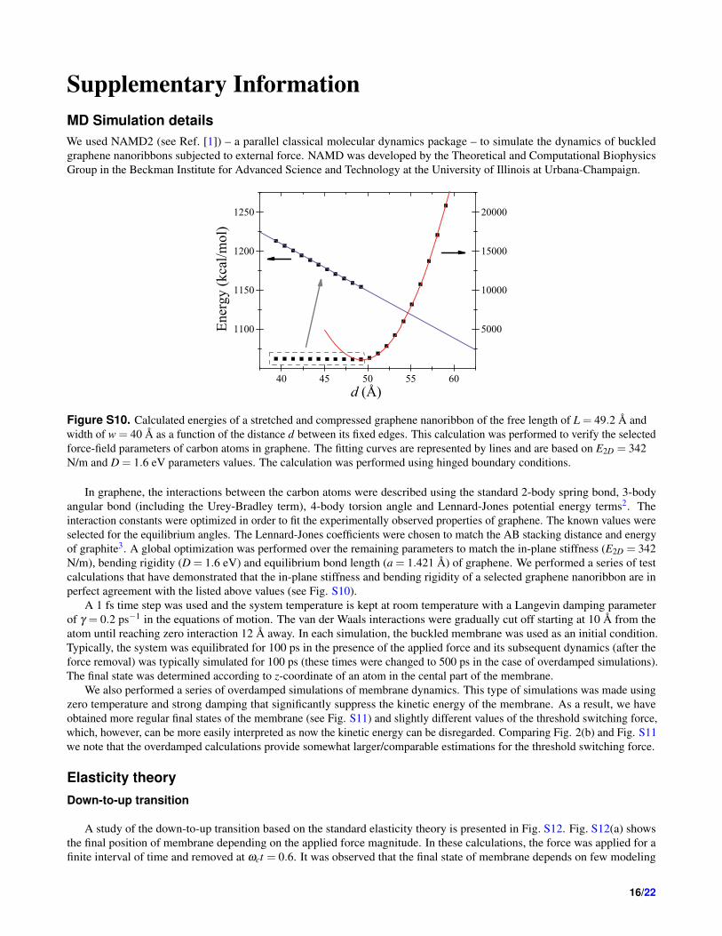
Figure S10. Calculated energies of a stretched and compressed graphene nanoribbon of the free length of L = 49.2 A andwidth of w = 40 A as a function of the distance d between its fixed edges. This calculation was performed to verify the selectedforce-field parameters of carbon atoms in graphene. The fitting curves are represented by lines and are based on E2D = 342N/m and D = 1.6 eV parameters values. The calculation was performed using hinged boundary conditions.
In graphene, the interactions between the carbon atoms were described using the standard 2-body spring bond, 3-bodyangular bond (including the Urey-Bradley term), 4-body torsion angle and Lennard-Jones potential energy terms2. Theinteraction constants were optimized in order to fit the experimentally observed properties of graphene. The known values wereselected for the equilibrium angles. The Lennard-Jones coefficients were chosen to match the AB stacking distance and energyof graphite3. A global optimization was performed over the remaining parameters to match the in-plane stiffness (E2D = 342N/m), bending rigidity (D = 1.6 eV) and equilibrium bond length (a = 1.421 A) of graphene. We performed a series of testcalculations that have demonstrated that the in-plane stiffness and bending rigidity of a selected graphene nanoribbon are inperfect agreement with the listed above values (see Fig. S10).
A 1 fs time step was used and the system temperature is kept at room temperature with a Langevin damping parameterof γ = 0.2 ps−1 in the equations of motion. The van der Waals interactions were gradually cut off starting at 10 A from theatom until reaching zero interaction 12 A away. In each simulation, the buckled membrane was used as an initial condition.Typically, the system was equilibrated for 100 ps in the presence of the applied force and its subsequent dynamics (after theforce removal) was typically simulated for 100 ps (these times were changed to 500 ps in the case of overdamped simulations).The final state was determined according to z-coordinate of an atom in the cental part of the membrane.
We also performed a series of overdamped simulations of membrane dynamics. This type of simulations was made usingzero temperature and strong damping that significantly suppress the kinetic energy of the membrane. As a result, we haveobtained more regular final states of the membrane (see Fig. S11) and slightly different values of the threshold switching force,which, however, can be more easily interpreted as now the kinetic energy can be disregarded. Comparing Fig. 2(b) and Fig. S11we note that the overdamped calculations provide somewhat larger/comparable estimations for the threshold switching force.
Elasticity theoryDown-to-up transition
A study of the down-to-up transition based on the standard elasticity theory is presented in Fig. S12. Fig. S12(a) showsthe final position of membrane depending on the applied force magnitude. In these calculations, the force was applied for afinite interval of time and removed at ωct = 0.6. It was observed that the final state of membrane depends on few modeling
16/22

z ct f
d/Ld/Ld/L
Figure S11. Up-to-down transition: the final position of a central atom of membrane as a function of the applied forcemagnitude in an overdamped calculation (T = 0, γ = 1 ps−1) for membrane B (42 rings length).
parameters (the applied force, damping rate, etc.). The possibility of the down-to-up transition is clearly seen in Fig. S12(a).The time-dependence of harmonics amplitudes is exemplified in Fig. S12(b) for a particular value of force. We note that inFig. S12(b) the amplitudes qn are normalized to q0 at t = 0. Fig. S12(b) shows that the harmonics amplitudes are modified bythe applied force (e.g., it is clearly seen that |q0(t)/q0(0)|> 1 at ωct < 0.6). Importantly, the amplitudes of higher harmonicsare small and can be neglected.
0 10 20 30 40 50 60 70
-30
-20
-10
0
10
20
30
(a)
z c(tf )
(A
)
Force (pN/atom)
d/L = 0.98 d/L = 0.95 d/L = 0.9 d/L = 0.85 d/L = 0.8
0.0 0.2 0.4 0.6 0.8 1.0 1.2 1.4
-1.0
-0.5
0.0
0.5
1.0(b)
q n(t)
/ q0(0
)
�ct
q0
q1
q2
q3
q4
Figure S12. Numerical simulation of the down-to-up transition. (a) The central-point deflection ζc versus the appliedtransverse force F for several values of d/L. Snapping-through appears at the critical force value F = F↑. (b)Time-dependence of the first few harmonics amplitudes qn(t).
17/22

Phenomenological Elasticity Theory
The Cartesian coordinates, which give the position of a membrane element defined by the internal coordinate s, are relatedto the angle θi (see Eqs. (16) and (17)) as
xi(s) = Ls∫
−1/2
cosθi(s′)ds′, (S36)
ζi(s) = Ls∫
−1/2
sinθi(s′)ds′. (S37)
According to the above equations, xi(−1/2) = 0 and ζi(−1/2) = 0. Another pair of boundary conditions is given by
xi(1/2) = d, ζi(1/2) = 0. (S38)
In the limit of small deflections, the boundary conditions, Eq. (S38), can be resolved for the coefficients Ai and ci in Eqs. (16)and (17):
As = ±48√
385√
1− dL√
5−88c20 +528c4
0
, (S39)
c2 = − 120
c1, (S40)
Ans = ±c1240
√35√
1− dL√
1200c41−56c2
1 +3. (S41)
Therefore, the value of a single parameter c0 (or c1) defines completely the symmetric (or non-symmetric) shape of membrane.In the case of the symmetric shape of membrane (Eq. (16)), at F = 0, there are two possible solutions of Eq. (19):
c0,1 =
√√5
11+
37132≈ 0.6954 (S42)
and
c0,2 =12
√133
(37−12
√5)≈ 0.2775 (S43)
valid for any d/L. These values correspond to the bending energies Ub,s,1(2) = k1(2)Dw(L−d)/L2 with k1 = 39.5 (minimum ofUb,s) and k2 = 200.5 (maximum of Ub,s). The corresponding geometries are shown in Fig. S13. Importantly, the snap-throughtransition of membrane takes place as c0 changes from 0.6954 to 0.2775. We note that Eq. (19) can be used to find Fs neededto ’support’ the membrane profile defined by a given value of c0.
The force as a function of zcm is presented in Fig. S14 for several values of d/L.
Dynamic regimeHere we assume that the membrane transition is induced by an abruptly applied force (similar to the case of our MD simulations).Under the assumption of energy conservation, the threshold switching force can be found from the condition that the initialenergy equals the potential energy barrier height (that depends on the applied force).
Technically, the calculation can be performed as follows. The value of parameter ci, c∗i (F), corresponding to the maximumof U =Ub +Uext (in the presence of F , see Eq. (18)) can be obtained from dU/dci = 0. Next, c∗i (F) is substituted into
Ub(c0
i)+Fζ
(c0
i)=Ub (c∗i )+Fζ (c∗i ) , (S44)
where c0i corresponds to the potential energy minimum at F = 0 (note that Ub(c0
i ) is the energy corresponding to k1 given belowEq. (S43)). Finally, the threshold switching force is found from Eq. (S44).
If one assumes that, at t = 0, the membrane has the non-symmetric profile, then one can get that the dynamic thresholdswitching force is the same as F↓ns given by Eq. (21). This result, however, should only be used as an upper estimate.
18/22

0.0 0.2 0.4 0.6 0.8
-0.05
0.00
0.05
0.10
0.15
z/L
x/L
c0 = 0.6954 c
0 = 0.3589 c
0 = 0.2775
Figure S13. Symmetric shapes of membrane calculated at d/L = 0.95. The curves from the top to bottom: the geometryminimizing the bending energy, geometry at the threshold switching force, and geometry maximizing the bending energy.
Indeed, initially, the membrane has the symmetric profile and determining the exact point of switching from the symmetric tonon-symmetric shape is a challenge.
Unfortunately, the above mentioned equations can not be solved analytically for the transition through the symmetricprofile. Figure S15 shows the numerically found potential energy as a function of position of the center of mass for severalrepresentative values of the applied force. This plot demonstrates that the potential barrier height becomes lower than the initialenergy when the applied force becomes larger than the threshold switching force Fsw.
Various threshold switching forces for the up-to-down transitions are summarized in Fig. 8 together with the results ofour MD and DFT calculations. This plot shows that F↓ provides the best phenomenological approach estimation for our MDresults. The deviation of MD points from F↓ curve at smaller d/L can be related to the approximation of small deflectionsused in our analytical model. Additionally, MD simulations involve energy relaxation channels not included into the simplifiedmodel given by Eq. (S44). Overall, however, we are quite satisfied with the results of our phenomenological model.
DFT CalculationsComputational detailsOur DFT calculations were carried out using the Jaguar quantum-chemistry5 package within the electron density functionalapproach with the use of a Becke three-parameter hybrid functional6, a Lee–Yung–Parr correlation functional7 (the B3LYPmethod), and a 6-31G basis set of atomic orbitals. Optimization of structures was performed by an analytical method up to agradient of the displacement of atomic positions of 10−4 au. The minimum on the potential energy surface was identified bythe absence of imaginary values in the matrix of second derivatives. As a test calculation, we have identified that the stretchingof an armchair-edged graphene nanoribbon (L = 20.9 A, w = 14.7 A) yields the in-plane stiffness EDFT
2D = 338 N/m, which isin good agreement with the experimental value E2D = 340 N/m.8
We investigated a zigzag graphene nanoribbon of the length of L = 24.6 A (10 rings) and of the width of w = 11.4 A. Thedangling bonds at nanoribbon boundary were terminated by hydrogen atoms. The hinged boundary conditions were realized byfixing the armchair edges at all calculation steps. The nanoribbon D1 with clamped boundary conditions was constructed fromthe flattest configuration C1 (with hinged boundary conditions) by an elongation of each armchair side by two rings kept fixedduring calculations.
Up-to-down transitionFirst of all, we note that the optimization of unloaded configurations C1, C2, and C3 gives the bending rigidity DDFT = 1.75eV, which is in good agreement with the experimental value D = 1.6 eV9.
As reported in Ref. [4], while, the non-symmetric path of switching is preferable due to the lower energy barrier, at smalldeflections from the unloaded state, the nanoribbon tends to be symmetric. A detailed investigation of the up-to-down transitionof D1 shows that at small deformations, the difference between the energies of the symmetric and assymetric shapes is small(for instance, the initial displacement of membrane by 0.5 A requires about 0.02 eV and 0.05 eV for the symmetric and
19/22

-0.10 -0.05 0.00 0.05 0.10 0.150
50
100
150
200
Fs (
in u
nits
of
Dw
/L2 )
zcm
/L
d/L=0.98 d/L=0.95 d/L=0.8
Figure S14. The applied force Fs as a function of zcm found for the symmetric membrane profile in the adiabatic switchingregime. The maximum of Fs corresponds to the threshold switching force through the symmetric membrane profile.
-0.04 -0.02 0.00 0.02 0.04 0.06 0.08
0.0
0.5
1.0
1.5
2.0
2.5 to switched down
U (
in u
nits
of
Dw
/L)
zcm
/L
F<Fsw
F=Fsw
F>Fsw
switched up
Figure S15. Potential energy landscape for the symmetric switching at several values of the applied force and d/L = 0.95.
non-symmetric paths, respectively, see Fig. S16(a)). However, the energy difference between the paths increases significantlywith deformation. When the positions of central atoms are close to the level of fixed edges, the deformation energy hasa maximum, which was used to estimate the up-to-down threshold switching force4. We note that the symmetric path inFig. S16(a) was generated by an increase of the z-coordinate of central atoms starting at z∼ 0.
The deformation energy of buckled graphene membrane with hinged boundary conditions is plotted in Fig. S16(b). In thecase of hinged boundary conditions, only the non-symmetric path has been identified in the framework of our DFT approach. Itwas found that the transition energy barrier is smaller for larger values of d/L.
Overall, the up-to-down threshold switching force estimated from DFT calculations agrees with both MD simulation andelasticity theory results (see Fig. 8). This plot presents the threshold switching force in the units of Dw/L2 for C1 and C2configurations. We note that the DFT value for the threshold force for C3 is about 235.3Dw/L2. As d/L of C3 is significantlyless than 1, the DFT threshold switching force for C3 is not the right quantity to compare with results of the linear elasticitytheory.
Stability of buckled membraneThe information storage time in the state of buckled membrane is limited by the finite temperature which leads to thermally-activated switching between two stable membrane states at long times. In the classical approach10, the rate constant k of
20/22

Figure S16. DFT deformation energy versus the position of central atoms in the process of the up-to-down switching. Basedon DFT approach, we were able to identify (a) both symmetric and non-symmetric paths for the case of clamped boundaryconditions, and (b) only the non-symmetric path for the case of hinged boundary conditions.
thermally-activated switching can be approximately described by Arrhenius equation
k = A · e−Eb
kBT , (S45)
where A is the pre-exponential factor (according to some more advanced theories11, 12, it describes the energy distributionin the system) and Eb is the potential barrier height. In the case of buckled membrane, Eb corresponds to the energy of theintermediate asymmetric state of membrane during its switching (the saddle point state) with respect to the energy of its stablestates.
Next we make an estimation for the thermally-activated switching time of d/L = 0.94 membrane of type B (a detailed studyof the membrane stability is beyond the scope of this paper). For this purpose we first performed a series of MD simulations ofthe dynamics of d/L = 0.98 membrane without applied force. These simulations have indicated that d/L = 0.98 membranestays in its initial state for at least 10 ns without switching (this is, of course, an underestimate of its storage time). Then,assuming that the change of the pre-exponential factor in Eq. (S45) with d/L compared to the corresponding change in theexponential factor is not significant, and using E0.98 = 0.60 eV, E0.94 = 1.8 eV, and T = 300 K one finds k−1 > 40,000 years.Clearly, such stability is sufficient for practical applications.
21/22

References1. Phillips, J. C. et al. Scalable molecular dynamics with namd. J. Comp. Chem. 26, 1781–1802 (2005).
2. Vanommeslaeghe, K. et al. CHARMM general force field: A force field for drug-like molecules compatible with theCHARMM all-atom additive biological force fields. J. Comp. Chem. 31, 671–690 (2010).
3. Chen, X., Tian, F., Persson, C., Duan, W. & Chen, N.-X. Interlayer interactions in graphites. Sci. Rep. 3, 3046 (2013).
4. Sedelnikova, O. V., Bulusheva, L. G., Okotrub, A. V. & Pershin, Y. V. Spontaneous symmetry breaking during the switchingof a buckled graphene membrane. JETP Lett. 103, 244–247 (2016).
5. Jaguar, version 7.9 (Schrodinger LLC, New York) (2012).
6. Becke, A. D. Density functional thermochemistry. iii. the role of exact exchange. The J. Chem. Phys. 98, 5648–5652 (1993).
7. Lee, C., Yang, W. & Parr, R. G. Development of the Colle-Salvetti correlation-energy formula into a functional of theelectron density. Phys. Rev. B 37, 785–789 (1988).
8. Lee, C., Wei, X., Kysar, J. W. & Hone, J. Measurement of the elastic properties and intrinsic strength of monolayer graphene.Sci. 321, 385–388 (2008).
9. Zhang, D.-B., Akatyeva, E. & Dumitrica, T. Bending ultrathin graphene at the margins of continuum mechanics. Phys. Rev.Lett. 106, 255503 (2011).
10. Atkins, P. & de Paula, J. Atkins’ physical chemistry (Oxford University Press, New York, 2014).
11. Eyring, H. The Activated Complex in Chemical Reactions. J. Chem. Phys. 3, 107 (1935).
12. Hanggi, P., Talkner, P. & Borkovec, M. Reaction-rate theory: fifty years after Kramers. Rev. Mod. Phys. 62, 251 (1990).
22/22