Embed Size (px)
Citation preview

Report
for
Alberta Agriculture, Food and Rural Development
Biogas Energy Electricity Generation and Interconnection to the Power Grid
January 05, 2006

AAFRD January 05, 2006 Biogas Energy Electrical Generation & Energy Reliability Services Inc. Interconnection to the Power Grid
1. Executive Summary Increasing energy prices and the availability of new small generation technologies are encouraging many small consumers and mid-sized business to consider alternative energy sources. Renewable energy sources include power from wind, solar, hydro and biomass projects. Alberta Agriculture Food and Rural Development would like to develop the steps required to effectively interconnect small and mid-sized generation applications to the electrical utility systems. The steps for interconnection will provide an easily followed outline of actions to be taken in developing a facility. The recommendations will identify items that would allow individual producers the flexibility required to develop the generation from numerous available agriculture feedstocks. The report encompasses individual producers capable of producing generation to offset their own load, and generation from commercial sized facilities with excess electrical capacity available to the Alberta Integrated Electric System (AIES). This report covers generation sizes typically from 10 kilowatts to 5 megawatts that are generally connected to the distribution system (25kV and below). While this report will focus mainly on generation interconnections for Biogas Plants supplied from numerous agricultural feedstocks, the processes, discussions and technical requirements are common to generation interconnections from all renewable energy sources. The report reviews the existing generation interconnection requirements and will map out a simplified process for interconnections with identification of barriers and gaps in order to facilitate a straight forward, easily understandable generation interconnection process. A discussion of Net Metering is included. The development of a streamlined process and elimination of barriers are intended to unleash the huge potential market that is available for renewable energy sources. These choices will lead to reduced emissions, improved reliability and efficiency, and provide greater security in the event of energy shortages The challenge now is for the governments and industry regulators to encourage this new, evolving industry to grow quickly in a way that is both safe and efficient.
Phone (403) 813-1589 200 Edgevalley Way N.W. Calgary, AB T3A 5E2 email: [email protected] Page 2 of 46

AAFRD January 05, 2006 Biogas Energy Electrical Generation & Energy Reliability Services Inc. Interconnection to the Power Grid
2. Table of Contents 1. EXECUTIVE SUMMARY................................................................................................................................2 2. TABLE OF CONTENTS...................................................................................................................................3 3. GLOSSARY OF TERMS..................................................................................................................................5 4. LIST OF ACRONYMS......................................................................................................................................6 5. OBJECTIVE: .....................................................................................................................................................7 6. INTRODUCTION..............................................................................................................................................7 7. BACKGROUND ................................................................................................................................................8
7.1. ELECTRICAL POWER AND ENERGY NEEDS ..................................................................................................8 7.1.1. Needs of household or business .............................................................................................................8 7.1.2. Electrical Needs of the Province............................................................................................................8
7.2. DEFINITION OF POWER ................................................................................................................................9 7.3. GENERATORS ..............................................................................................................................................9
7.3.1. Induction Generators.............................................................................................................................9 7.3.2. Synchronous Generators......................................................................................................................10 7.3.3. Generator Terminal Voltage Level ......................................................................................................10
7.4. DISTRIBUTION NETWORKS ........................................................................................................................10 7.5. ISLANDING ................................................................................................................................................12 7.6. METERING.................................................................................................................................................12
7.6.1. Standard Meter ....................................................................................................................................12 7.6.2. Detent Meters.......................................................................................................................................12 7.6.3. Bi-directional meters. ..........................................................................................................................13 7.6.4. 2 Detent Meters....................................................................................................................................13 7.6.5. Interval Meters.....................................................................................................................................13
8. OPPORTUNITIES IN AGRICULTURE ......................................................................................................13 8.1. BIOMASS OPPORTUNITIES IN AGRICULTURE .............................................................................................13 8.2. PARTNERSHIPS WITHIN GOVERNMENT ......................................................................................................16
9. TECHNICAL PROCESS ................................................................................................................................17 9.1. SAFE OPERATIONS.....................................................................................................................................17 9.2. GENERATION PROCESS..............................................................................................................................17 9.3. INTERCONNECTION PROCESS.....................................................................................................................17
9.3.1. Production of electrical energy for ‘Use at Site’ vs. ‘Selling into the Power Grid’. ...........................18 9.4. INTERCONNECTION REQUIREMENTS..........................................................................................................18
9.4.1. ATCO Electric .....................................................................................................................................18 9.4.2. FortisAlberta........................................................................................................................................18 9.4.3. ENMAX................................................................................................................................................19 9.4.4. IEEE Guide..........................................................................................................................................19 9.4.5. Table 9.4. Summary of Interconnection Requirements ........................................................................19
10. NET METERING .......................................................................................................................................20 11. BUSINESS INTERCONNECTION PROCESS .......................................................................................22
11.1. THE INDEPENDENT SYSTEM OPERATOR (AESO) REQUIREMENTS.............................................................22 11.2. ALBERTA ENERGY AND UTILITIES BOARD (AEUB) REQUIREMENTS ........................................................24 11.3. UTILITY REQUIREMENTS ...........................................................................................................................25 11.4. SUMMARY OF STEPS IN GENERATING AND BECOMING INTERCONNECTED ................................................26
Phone (403) 813-1589 200 Edgevalley Way N.W. Calgary, AB T3A 5E2 email: [email protected] Page 3 of 46

AAFRD January 05, 2006 Biogas Energy Electrical Generation & Energy Reliability Services Inc. Interconnection to the Power Grid
12. COSTS AND BENEFITS OF SMALL, LOCAL GENERATION..........................................................27 12.1. BENEFITS TO SOCIETY OF BIOGAS FACILITIES ............................................................................................27
12.1.1. Reduction of emissions....................................................................................................................27 12.1.2. Generate revenue by selling electricity or gas................................................................................27 12.1.3. Earn tax credits for renewable energy production .........................................................................27 12.1.4. Sell Green Tags, or carbon credits, the environmentally beneficial attributes of the renewable energy. 27 12.1.5. Eliminate odor issues. .....................................................................................................................27 12.1.6. Earn tipping fee revenue for treating waste....................................................................................28 12.1.7. Make compost sales revenue...........................................................................................................28 12.1.8. Avoid regulatory penalties for manure management issues............................................................28 12.1.9. Offset power & heating costs. .........................................................................................................28 12.1.10. Deferral of generation, transmission, and distribution infrastructure............................................28 12.1.11. Potential for increased Reliability ..................................................................................................28
12.2. COSTS TO SOCIETY ....................................................................................................................................28 12.2.1. Maintain infrastructure...................................................................................................................29 12.2.2. Provide back up supplies ................................................................................................................29
12.3. BENEFITS TO THE DEVELOPER ...................................................................................................................29 12.3.1. Stand alone plant for local use........................................................................................................29 12.3.2. For sales to the Interconnected System...........................................................................................29
13. A SAMPLE ECONOMIC EVALUATION...............................................................................................29 13.1. INTERCONNECTION EXAMPLES..................................................................................................................29
13.1.1. Typical Load Supply........................................................................................................................29 13.1.2. Generation Plant via Existing Load transformer Supply ................................................................32 13.1.3. Generation Plant via Step – Up Transformer .................................................................................34 13.1.4. Generation Plant via Step Up Transformer and Existing Supply ...................................................36
13.2. SAMPLE COSTS..........................................................................................................................................38 14. BARRIERS / GAPS IDENTIFICATION..................................................................................................39 15. CONCLUSIONS AND RECOMMENDATIONS ....................................................................................40 15. REFERENCES............................................................................................................................................42 16. BIOGRAPHIES...........................................................................................................................................42
16.1. STAN C. GORDEYKO, P.ENG......................................................................................................................42 16.2. ALLEN L. ROTHBAUER, P.ENG. .................................................................................................................43
FIGURE 1 - ELECTRIC TRANSMISSION SYSTEM INPROXIMITY TO THE COUNTY OF LETHBRIDGE ..........................................................................................................................................................44 FIGURE 2 – MANURE PRODUCTION INDEX FOR ALBERTA .....................................................................45 FIGURE 3 – WIRE OWNERS GEOGRAPHIC SERVICE AREAS ...................................................................46
Phone (403) 813-1589 200 Edgevalley Way N.W. Calgary, AB T3A 5E2 email: [email protected] Page 4 of 46

AAFRD January 05, 2006 Biogas Energy Electrical Generation & Energy Reliability Services Inc. Interconnection to the Power Grid
3. Glossary of Terms
Alberta Interconnected Energy Electric System (AIES)
As prescribed in the Electric Utilities Act means all transmission facilities and all electric distribution systems in Alberta that are interconnected, but does not include an electric distribution system or a transmission facility within the service area of the City of Medicine Hat or a subsidiary of the City, unless the City passes a bylaw that is approved by the Lieutenant Governor in Council under section 138
Billing Period The time period over which a power bill is caluclated. This is usually a period of 1 month.
Demand The amount of power consumed in a 15 minute interval during the billing period. Usually expressed as kW (kilowatts)or kVA (kilovoltampers). This is the capacity required from the system to serve the load.
Distributed Generator(DG) A generator that is interconnected to the electric distribution system
Distributed Resource (DR) A collective term referring to all sources of real electric power that are not directly connected to the bulk power transmission system.
Distribution System The portion of the AIES electrical system operating at 25kV (25,000 volts) or less.
Electric Power System - Local(Local EPS)
An EPS contained entirely within a single premises or group of premises
Electric Power System (EPS) Facilities that deliver electric power to a load
Energy Energy is measured in the units of watt-hour (Wh) or the kilowatt-hour (kWh). Energy is equal to Power (required/delivered) over a period of time in hours.
Interconnection System The collection of all interconnection equipment and functions, taken as a group, used to interconnect a DR unit(s) to an EPS.
Islanding A scenario where a portion of the utility’s distribution system is energized exclusively by one or more power producers through their DR interconnection.
Meter Means an electric or gas meter and includes any apparatus used for the purpose of making measurements of, or
Phone (403) 813-1589 200 Edgevalley Way N.W. Calgary, AB T3A 5E2 email: [email protected] Page 5 of 46

AAFRD January 05, 2006 Biogas Energy Electrical Generation & Energy Reliability Services Inc. Interconnection to the Power Grid
obtaining the basis of a charge for, electricity or gas supplied to a purchaser;
Net Metering Net Metering is the use of a cumulative meter to measure both generation and consumption by allowing the meter to turn backwards during a meter reading period and provide a credit for the energy exported at the retail rate. Any net credit (more exported than consumed) in a billing period would be carried forward to the next period or credited in some other manner.
Parallel Operation Any electrical connection between the utility distribution system and the power producer’s generating facility.
Point of Common Coupling The point at which the wires owners facilities are connected to the distributed generator facilities and where any transfer of electrical energy between the DG Owner and Wire Owner is deemed to take place.
Point of Interconnection (POI)
The location of the electrical connection between a power producer’s DR facility and the utility’s distribution system.
Self Generation Generation of electrical capacity and energy for the use within ones own facility
Wire Owner The owner of the wires or Electric Power System (EPS) that distribute electrical energy to consumers.
4. List of Acronyms.
AESO Alberta Electric System Operator
AEUB Alberta Energy and Utilites Board
AIES Alberta Interconnected Electric System
DFO Distribution Facilities Owner
DG Distributed Generation
DR Distributed Resources
EPS Electric Power System
GFO Generation Facilities Owner
I Current in Amps
MSP Meter Service Provider
kV Kilovolts (a thousand volts)
KVA Kilo voltamps (a thousand volt amps)
Phone (403) 813-1589 200 Edgevalley Way N.W. Calgary, AB T3A 5E2 email: [email protected] Page 6 of 46

AAFRD January 05, 2006 Biogas Energy Electrical Generation & Energy Reliability Services Inc. Interconnection to the Power Grid
kW Kilowatt (a thousand watts)
MVA Mega voltamps (a million volt amps)
PCC Point of Common Coupling
TFO Transmission Facilities Owner
V Volts
WO Wire Owner
5. Objective: This report is intended to outline the steps required to effectively interconnect small and medium sized generation to the electrical utility systems. In addition, recommendations are included that could lead to the development of policy and legislation, which could allow individual producers the additional flexibility required to develop the generation from numerous available agriculture feedstocks. The report includes, at a high level, what an individual producer might do with their own generation to offset their own load. Additionally what might be done with commercial sized facilities with excess electrical capacity to supply energy into the Alberta Interconnected Electric System (AIES) with financial compensation for this contribution. This report generally covers generation sizes from 10 kilowatts to a maximum of 5 megawatts which would be connected to the electrical distribution system of twenty five thousand volts (25 kV) and below. The principles identified would be applicable to units of larger size however these would normally be connected to the electrical grid which operates at a voltage above 25 kV (at a transmission voltage).
6. Introduction The report summarizes the current generation interconnection guidelines and requirements in Alberta and the opportunities for change in the current practices that would allow small generation interconnections to move forward in a straight forward, easily understood way. The report includes the steps to be taken to enable small generation interconnections to proceed more easily. The concept of net metering or net zero interconnection is reviewed and discussed. The possibilities for producers with limited generation capacity that only offsets their entire load are also reviewed. The report is focused on distributed generators interconnecting synchronously to the three phase distribution system. The generator sizes will range from 10 Kilowatts to 5000 Kilowatts (5 Megawatts). While not the specific focus, micro - generators and fuel cells with inverters are rapidly evolving and their interconnections can use most of the content of this report. The review of existing generation interconnection guidelines including guidelines from ATCO, FortisAlberta, AESO, ENMAX and IEEE has been undertaken. The requirements for producers with not enough generation to offset their entire load will be addressed in particular. The following will be addressed in this report.
• Existing Interconnections Guidelines
Phone (403) 813-1589 200 Edgevalley Way N.W. Calgary, AB T3A 5E2 email: [email protected] Page 7 of 46

AAFRD January 05, 2006 Biogas Energy Electrical Generation & Energy Reliability Services Inc. Interconnection to the Power Grid
• Net Metering • Opportunities for Return on Investment • Business Interconnection Process • Technical Interconnection Process • Production of Electricity - Farm Use Only • Production of Electricity – Selling to the Grid • Sample Interconnections Costs
7. Background
7.1. Electrical Power and Energy Needs In deciding whether or not to proceed with a project and to assist in deciding what type of project to proceed with the local site load must be determined. There must be some level of certainty of the amount of energy that can be produced and delivered to the power grid in order to complete an economic analysis. Current and historical retail rates are available at the following site: http://www.customerchoice.gov.ab.ca/Who_Provides-Competitive_Search.html
7.1.1. Needs of household or business Our society has grown very dependant on our use of electrical energy over the last century. It affects almost every aspect of our lives at home, at work, and at play. The average household in Alberta1 consumes approximately 650 kWh per month. Current customers served from the power grid will be able to determine their energy requirements by looking at their billing history. Larger loads will have a demand reading, which is an indication of the capacity required from the system to serve the load. Business requirements will take some additional effort in determining what the electrical requirements are. For Business there are generally more motor type loads, which draw significantly more “power” on start up than they do in their normal running condition. A detailed inventory of what loads, including the characteristics of the loads, are required for the business’s electrical system. The results of this inventory should be reviewed by a person knowledgeable in load diversity and load starting requirements so that the load capacity requirements are neither over or under estimated.
7.1.2. Electrical Needs of the Province Within the province the present forecast demand for electricity (power) is 9,594 MW (megawatt or million watts) and the present forecast consumption of electricity (energy) is 67,207 Gwh (million kilowatt hours). The quantity of this demand and consumption, which is supplied from the Alberta Electrical Grid, is 8,113 Mw and 56,636 Gwh.2 The difference between the forecast requirements and the electricity supplied from the grid is generated and used within the users own property at the generator site. Alberta’s energy
1 Alberta Government Services, Consumer Services Branch, “Consumer Tips, January 2004”
2 AESO “FUTURE DEMAND AND ENERGY REQUIREMENTS (Period: 2004 – 2024) Document: FC-2004-1 June 2004”
Phone (403) 813-1589 200 Edgevalley Way N.W. Calgary, AB T3A 5E2 email: [email protected] Page 8 of 46

AAFRD January 05, 2006 Biogas Energy Electrical Generation & Energy Reliability Services Inc. Interconnection to the Power Grid
requirements are forecast to increase by 2.3% per year over the next five years, and by 2.1% per year over the next ten years. Demand is forecast to increase by 2.1% per year over the next five years, and by 2.0% per year over the next ten years. This creates an expanding market which will have steady if not increasing energy costs or prices. There is ample opportunity for large commercial generation and small distributed generation.
7.2. Definition of Power
Alternating Current (AC) power flow has the three components: real power (P), measured in watts (W); apparent power (S), measured in volt-amperes (VA); and reactive power (Q), measured in reactive volt-amperes (VAR). The power factor of an AC electric power system is defined as the ratio of the real power to the apparent power. Real power is the capacity of the circuit for performing work in a particular time. Due to reactive elements of the load, the apparent power, which is the product of the voltage and current in the circuit, will be equal to or greater than the real power. The reactive power is a measure of the stored energy that is reflected to the source during each alternative current cycle. Reactive loads such as inductors and capacitors dissipate zero power, yet the fact that they drop voltage and draw current gives the deceptive impression that they actually do dissipate power. This "phantom power" is called reactive power, and it is measured in a unit called Volt-Amps-Reactive (VAR), rather than watts. If a purely resistive load is connected to a power supply, current and voltage will be in phase, and the power factor will be unity (1). Inductive loads such as transformers and motors (any type of wound coil) generate reactive power with current waveform lagging the voltage and a lagging power factor less than 1. Capacitive loads such as capacitor banks or buried cables generate reactive power with current phase leading the voltage and a leading power factor less than 1.
7.3. Generators Generators convert mechanical energy (rotating shaft horsepower) into electricity. The output can be either AC or DC. AC generators can be single phase or 3 phase. They are one of 2 types: induction or synchronous.
7.3.1. Induction Generators Induction generators are similar to induction motors. They are often started as a motor using utility power. Once started, the mechanical power source rotates the shaft in excess of the unit’s ‘motoring’ speed producing electrical energy. Induction generators are typically smaller than 500kW and do not require synchronizing equipment to tie onto the system. Although induction generators produce real power, they require reactive power from the utility for excitation. As a result, capacitors installed on the generator side of the generator breaker, are often used to provide VAR support. Induction Generators costs are typically lower than Synchronous Generators and normally require a connection to the power system to operate.
Phone (403) 813-1589 200 Edgevalley Way N.W. Calgary, AB T3A 5E2 email: [email protected] Page 9 of 46

AAFRD January 05, 2006 Biogas Energy Electrical Generation & Energy Reliability Services Inc. Interconnection to the Power Grid
7.3.2. Synchronous Generators Synchronous generators use a DC field for excitation and can supply both watts and VARs to their load. They are capable of generating stable AC power independent of a utility system interconnection. Emergency back-up generators using fossil fuel combustion engines are typically synchronous machines. In fact, the majority of distributed generators interconnected for parallel operation are three-phase, synchronous machines. With proper controls the synchronous generators can be made to match various DFO requirements for voltage, frequency and powerfactor.
7.3.3. Generator Terminal Voltage Level The generators can be ordered to a number of standard voltages. For generators which would normally be connected to the distribution system, these voltages are generally 120V, 240V, 480V, 600V, 2400V, 4160 V. or 13.8kV. The voltage is usually based on the size of the generator. The greater the generator sizes the higher the voltage. From an interconnection perspective, the generator voltage determines the amount of current produced by the generator at full load and therefore the wire size required to carry the full generator output. Generally the higher the voltage the smaller the current and the conductors are for the same capacity requirement. A transformer is required to match the interconnection voltages between the generator and the power grid.
7.4. Distribution Networks Distribution power systems in Alberta are typically designed as radial lines that start at a transmission substation and radiate in different directions to supply distributed loads with a voltage of 25 kV.. Refer DWG - Typical Distribution Network. Typically one or two high voltage power lines (138 kV) provide power to a large substation. At the substation a transformer lowers the voltage from 138 kV to 25 kV. Generally at each substation the transformer is equipped with a voltage regulating device that maintains voltage within acceptable limits. Two to four 25 kV breakers are installed to distribute power via the 25 kV distribution lines to various loads. Each of the 25 kV lines can run up to 50 km and depending on conductor size and distance can supply from 8 to 20 MVA of load. The 3 phase 25 kV distribution lines run to major load centers (towns) and larger commercial centers (plants, feedlots) where the voltage is stepped down to lower voltages to service commercial operations and businesses. Single phase feeders are tapped off the main 25 kV line to distribute power to individual farms and residences. The single phase loads range from approximately 5 KVA to 50 KVA. Energy losses in transmission lines and distribution lines increase with increasing current. Where a load has a power factor lower than 1, more current is required to deliver the same amount of useful energy. Power companies therefore require that customers, especially those with large loads, correct the power factors of their respective loads within specified limits or be subject to additional charges.
Phone (403) 813-1589 200 Edgevalley Way N.W. Calgary, AB T3A 5E2 email: [email protected] Page 10 of 46

AAFRD January 05, 2006 Biogas Energy Electrical Generation & Energy Reliability Services Inc. Interconnection to the Power Grid
Typical Distribution Network.
POD Metering M
Typical Distribution System
M
TFO 138 kV Line
152 45235225225 kV Breakers
25 kV Bus
3 Phase Load
To Loads To Loads
3 Phase Load
3 Phase Load
3 Phase Load
3 Phase Load
3 Phase Load
3 Phase Load
3 Phase Load
3 Phase Load
3 Phase Load
3 Phase Load
3 Phase Load
1 Phase Load
1 Phase Load
1 Phase Load
1 Phase Load
1 Phase Load
1 Phase Load
1 Phase Load
1 Phase Load
1 Phase Load
1 Phase Load
1 Phase Load
Phone (403) 813-1589 200 Edgevalley Way N.W. Calgary, AB T3A 5E2 email: [email protected] Page 11 of 46

AAFRD January 05, 2006 Biogas Energy Electrical Generation & Energy Reliability Services Inc. Interconnection to the Power Grid
7.5. Islanding One of the most important issues for small customer-sited systems is a condition called islanding. Islanding is where a portion of the utility system that contains both loads and a generation source is isolated from the remainder of the utility system but remains energized. The safety concern is that if the utility power goes down (perhaps in the event of a major storm), a distributed generation system could continue to supply power to a local area. While a utility can be sure that all of its own supply sources are either shut down or isolated from the area that needs work, an island created by an independent system can be out of their control. From a utility perspective, there are a number of potentially undesirable results of islanding. The principal concern is that a utility line worker will come into contact with a line that is unexpectedly energized. Although line workers are trained to test all lines before working on them, and to either treat lines as live or ground them on both sides of the section on which they are working, this does not remove all safety concerns because there is a risk when these practices are not universally followed. Another concern is that the islanded system will not be able to maintain the necessary power quality (voltage and frequency) to the loads within the island. DFO at this time do not allow islanding. With proper generator controls there should not be concerns regarding power quality. If a generator owner decided to run a generator in a standby mode or normally isolated from the system, these same power quality issues would need to be addressed.
7.6. Metering The role of the meters is traditionally to measure the net of what is happening on the load side of the meter for billing purposes. The types of meters available are discussed below.
7.6.1. Standard Meter The standard household electrical energy (kWh) meter is called a "cumulative" meter because it "accumulates" the power measurements, and provides an energy reading. Normally they measure electricity in both the forward and reverse modes and provide the net of both. The meter is normally supplied at zero cost by the DFO. The meter is read and billing is done routinely by the energy retailer. $0 to purchase, $0 for meter reading and meter data handling
7.6.2. Detent Meters The same standard household kWh meter can be latched to prevent it from operating in the reverse direction. This has also been referred to as a 1-way, unidirectional, or detented meter. This runs forwards for imported electricity and stops for exported electricity. It does not prevent the electricity from flowing backwards; it just doesn't measure it. The meter is normally supplied at zero cost by the DFO. The meter is read and billing is done routinely by the energy retailer. $0 to purchase, $0 for meter reading and meter data handling.
Phone (403) 813-1589 200 Edgevalley Way N.W. Calgary, AB T3A 5E2 email: [email protected] Page 12 of 46

AAFRD January 05, 2006 Biogas Energy Electrical Generation & Energy Reliability Services Inc. Interconnection to the Power Grid
7.6.3. Bi-directional meters. They consist of one meter but it has two latched registers on it that accumulate the electrical power measurements in both the import and export directions. As this is a special use meter there is a cost to purchase and have it installed. There will be a charge to use the features of the meter and have it read frequently Approximately $1000 to purchase, approximately $2 per day for meter reading and meter data handling
7.6.4. 2 Detent Meters Two standard detent cumulative meters can also be used for bi-directional metering. Each of the two meters accumulates power measurements in one of the import and export directions. As this is a special use meter set up there is a cost to purchase and have it installed. There will be a charge to use the features of the meter and have it read frequently. $150 to $1200 to purchase 1 additional meter, and a 2-meter socket base $ ?? for meter reading and data handling.
7.6.5. Interval Meters Large load customers and generators will have 4 quadrant, 1-way, electronic interval meters that store energy data every 15 minutes. These can be used with Automatic Meter Readers to download the energy data over the phone lines daily. These provide time of the use data for variable pricing tariffs and electricity trading systems. As this is a special use meter set up there is a cost to purchase and have it installed. There will be a charge to use the features of the meter and have it read frequently. $1500 to $3000 purchase $60 to $ 250 per month for meter reading and meter data handling.
Currently in the Alberta Interconnection Guidelines an interval meter must be installed at all distributed generation sites. The same metering is required for any parallel operation.
8. Opportunities in Agriculture
8.1. Biomass Opportunities in Agriculture Biomass is the organic matter available on a renewable basis. Biomass includes forest and mill residues, agricultural crops and wastes, wood and wood wastes, animal wastes, livestock operation residues, aquatic plants, fast-growing trees and plants, and municipal and industrial wastes.3 Within Alberta with its large amount of biomass in the form of boreal forest and significant amounts of waste from agricultural operations although from some perspectives seen as a large problem, has significant potential to benefit society in numerous ways.
3 www.biorenew.iastate.edu/resources/glossary.php
Phone (403) 813-1589 200 Edgevalley Way N.W. Calgary, AB T3A 5E2 email: [email protected] Page 13 of 46

AAFRD January 05, 2006 Biogas Energy Electrical Generation & Energy Reliability Services Inc. Interconnection to the Power Grid
Alberta is the largest beef cattle producer and fourth largest swine and poultry producer in Canada.4 Biogas operations have numerous advantages including production clean heat and electricity (for use in the agricultural operation and for sales), reducing the impact of organic wastes on the environment (i.e. reduced greenhouse gases and lower impact on water sources and courses) and enhancing the value of residual products. With proper design and operation digesters can accept substrates other than manure, from grease to corn silage. Even mixed food waste can be treated. Hog and dairy operations are well suited for biogas production. For economic viability, the bigger the operation, the better. Information from the United States suggests hog operations larger than 1000 pigs and dairy operations larger than 300 cows are best suited for biogas production. Some plants extract minerals and fibers from the manure and recycle them for other agricultural or industrial uses. These additional products from a digester can be used as feedstocks within the agricultural operations or can be marketed to assist in managing costs and revenues for the operation of the facility.
Biogas can be generated using the feedstocks from food processing plants such as canneries, slaughter operations, sugar beet operation, or potato chip operations. Straw left over from grain production can be used as an input to digesters. These wastes can be used in stand alone operations, associated processing operations, or used as input to digesters located at other facilities. Digesters can be located such that they can be used in conjunction with other processing plants requiring gas, steam, or electric energy as long as they are in close proximity. Biomass projects have an optimum size and location. The trade offs between fuel costs for the transportation of feedstocks and economies of scale of the operation of the facility must be considered. 5 In Denmark, large scale regional biogas digester plants have been built to treat manure from many large intensive livestock operations. Animal and other agricultural waste is brought to these plants on a daily basis for processing. If the concept of managing all wastes became a priority for our society and its governments these large regional processing facilities could become a reality.6
Alberta is the second largest agricultural producer in Canada in terms of farm cash receipts. The livestock industry in Alberta, which accounts for 62% of the provincial farm cash receipts, is a large and growing business worth over $5 billion per year. Our farms have changed from a large number of small mixed farming operation into specialized businesses, with farmers maintaining large numbers of a single animal type. In addition there are significant finishing and processing facilities. It is interesting to note that over 60% of the cattle in Alberta can be found in the south and central regions of the province, with a particularly high concentration in Lethbridge County (Feedlot Alley). As of July 1, 2005 there were 6.9 million nine head of cattle in the province. This number represents the
4 MANURE MANAGEMENT AND GREENHOUSE GAS MITIGATION TECHNIQUES: A COMPARATIVE ANALYSIS Climate Change Central DISCUSSION PAPER C3
– 013 Prepared by: Chris Langmead Date: September 3, 2003
5“Is biomass part of Alberta's energy future?” By Dr. Peter Flynn http://www.expressnews.ualberta.ca/article.cfm?id=5737
6 Biogas Plants Solve Manure Problem Will Verboven http://cattlefeeder.ab.ca/manure/manure020326.shtml
Phone (403) 813-1589 200 Edgevalley Way N.W. Calgary, AB T3A 5E2 email: [email protected] Page 14 of 46

AAFRD January 05, 2006 Biogas Energy Electrical Generation & Energy Reliability Services Inc. Interconnection to the Power Grid
potential production of 750 million kwh of energy annually with a potential revenue of in excess of $35 million annually.7 8There is a concentration of Cattle, Poultry, and Swine production along the major Highway #2, 3, and 1 with the associated manure production.9 This creates the potential for the efficient transport of wastes to centrally located digester plants that have efficiencies that are greater than local farm based digesters. As the Alberta livestock industry increases in density and size, there is need for adequate manure management systems.
Some of the factors stimulating the focus on the need to manage manure include: • Large numbers of confined feeding operations (CFOs) with large,
concentrated quantities of manure. • Public awareness of the potential impacts of the feedlot operations on water sources. • Provincial regulations regarding the operation of feedlots. • General public awareness of greenhouse gases and the potential impact on the
environment • Awareness in the agricultural industry of the potential to utilize “farm waste” products to
produce electricity and heat and thus reduce operating costs. • The recent increases in energy costs make these alternative manure management systems
more appealing.10 At the present time there is approximately 180 MW of the 12,100 MW (or 1.5%) of installed generating capacity in Alberta fuelled with biomass. For the most part these units are powered by biomass feed boilers, which produce process steam for heat and supply steam to a steam turbine generator. The biomass in these cases is waste wood from mill or pulp operations.
Recently there have been a few biogas generation operations, such as the IMUS11 (Integrated Manure Utilization System) feedlot generation facility that is located in the County of Two Hills, near Vegreville. Biogas, a combustible gas similar in character to natural gas, is derived from decomposing biomass organic waste. The gas consists of from 40 up to 80 percent methane, with 20 to 40 percent carbon dioxide, and trace amounts of other compounds such as hydrogen sulfide, ammonia, and water vapor. In the agriculture industry, biogas can be produced from abundant supplies of livestock manure. At the IMUS facility the manure from 10,000 head of cattle at Highland Feeders goes into digesters where it is anaerobically broken down into biogas. This gas is then fed into an engine that drives a generator with a capacity of 1MW. Heat from the engine is used for facility heat and in the digester process. Biogas can also be used to produce electricity through some technologies that are less proven but showing significant potential.12 These technologies are fuel cells and
7 Pool Prices – Monthly Averages http://www.epcor.ca/Customers/HomeSmallBus/Power/EstimatedDefaultSupplyRates.htm
8 Key Elements of Biogas Energy Systems Anaerobic Digesters Brian Gannon, Biogas Energy Systems [email protected]
9 A Geographical Profile of Manure Production in Canada http://www.statcan.ca/english/freepub/16F0025XIB/16f0025xib-l.pdf
10 MANURE MANAGEMENT AND GREENHOUSE GAS MITIGATION TECHNIQUES: Climate Change Central DISCUSSION PAPER C3 – 013 Prepared by: Chris
Langmead Date: September 3, 2003
11 The Power of the Feedlot - Faculty of Engineering - Magazine - University of Alberta
12 Biogas Mission to Austria & Germany in November 2005 - [email protected]
Phone (403) 813-1589 200 Edgevalley Way N.W. Calgary, AB T3A 5E2 email: [email protected] Page 15 of 46

AAFRD January 05, 2006 Biogas Energy Electrical Generation & Energy Reliability Services Inc. Interconnection to the Power Grid
micro turbines. Internal combustion engines are typically used to drive generators with from 1 kW to 500 kW, micro turbines power generators with less than 200 kW of capacity, and fuel cells typically have capacities in the range of 1 kW to 250 kW. The technical and requirements for using any of these technologies for electrical energy within the agricultural plant or to supply electricity to the grid are similar. A combined biogas/generation operation has numerous potential benefits. These include: • Reduction in the emission of greenhouse gasses • Production of additional “GREEN” renewable electricity • Enhanced rural sustainability and industrial growth • Enhanced environmental protection through manure management • Potential to enhance the residual products of the digestion process
From the data available it appears the County of Lethbridge has in excess of 11% the cattle population in the province, 7% of the swine population in the province, and in excess of 10 % of the poultry population of the province. The County also processes significant volumes of foodstuffs. Both of these factors provide the volumes of waste that could support a regional base digester operation. There has also been a significant commitment made to the environment and management of manure volumes within the county.13 When the power system is reviewed there are numerous transmission substations and therefore numerous distribution circuits within close proximity providing good opportunity for the interconnection of a biogas generation operation. If the a digester could be co-located with a food processing operation the heat requirements of the food processor may be met with the residual heat (about equivalent to the electrical energy production) from the digestion/generation process. Please see Figures 1 and 2 regarding the Electric Transmission System and The Manure Index in the area of Lethbridge.
8.2. Partnerships within Government There is a significant amount of capital required to invest in a digester/generation facility and interconnection. There are also a number of challenges in moving forward with a digester/generation project. On the electrical side in the deregulated environment there are now three parties; the AESO, the TFO, and the DFO; where there was one utility involved before deregulation. There are approvals required from Alberta Energy and Utilities Board both for the digester and for the electrical facilities and interconnection. There may be approvals required from Alberta Environment for the digester facility; certainly they have concerns for manure management and water resources. Other governmental agencies could be involved and support a digester project. Alberta Agriculture has concerns for sustainability and development of agricultural resources. Alberta Economic Development could see benefits from a digester project. Alberta Energy
13 Alberta Environmentally Sustainable Agriculture Program http://www.county.lethbridge.ab.ca/municipal/lethbridge/lethbridge-
website.nsf/AllDoc/28A1A61630AD935C872570A0007C3D1C/$File/aesa2004final_rpt.pdf
Phone (403) 813-1589 200 Edgevalley Way N.W. Calgary, AB T3A 5E2 email: [email protected] Page 16 of 46

AAFRD January 05, 2006 Biogas Energy Electrical Generation & Energy Reliability Services Inc. Interconnection to the Power Grid
has commitment to customer choice, the environment and green house gas reduction. The Alberta Reseach Council has been involved in projects and could support additional projects with their experience and learning. There is research going on in our universities that could add value to a project. Municipal governments are responsible for various development permits and can gain economic and social benefits from a development.
9. Technical Process
9.1. Safe Operations Safety of personnel, the public and of equipment is the primary concern in the design and operation of any interconnection.
9.2. Generation Process 1) Determine the total amount of energy that the new biogas plant load and generator will
require. 2) Determine the amount of total load that is required on site. This is available from your
current electricity retailer or can be determined through an audit of the site.. Normally this is presented as a demand amount (kW) and an energy amount (kWhrs) on your electricity bill.
3) The total of 1 & 2 will represent the total site or local electric system load. 4) Based on the availability of generator prime mover (fuel source), determine the optimum
size of generator to be used. The reliability requirements of the biogas plant and onsite generation should be considered in determining the optimum size.
5) Determine the generator voltage. This affects the size of the components which will be used to interconnect the facilities into the electric grid
6) Determine operating requirements of the plant and load. If at any time some of or the total site or local electric system load is required to be supplied without an interconnection to the grid a synchronous generator will be required.
7) An induction generator can be selected if there is no operational requirement to supply some of the local load independent of the utility network or there is no thought of using the generator for facility stand by operations.
8) Proceed with the Interconnection process
9.3. Interconnection Process 1) Notify the distribution wire owner of the project including the generator size, voltage,
and operating requirements of the generator plant & load. 2) In conjunction with Wire Owner, determine point of interconnection (POI) to the utility
distribution system. This is sometimes referred to as the point of common coupling (PCC).
3) Request interconnection proposal and costs from the Wire Owner. 4) Determine the revenue metering location and type of metering. 5) Approve Wire Owners proposal and agree to pay the interconnection costs.
Phone (403) 813-1589 200 Edgevalley Way N.W. Calgary, AB T3A 5E2 email: [email protected] Page 17 of 46

AAFRD January 05, 2006 Biogas Energy Electrical Generation & Energy Reliability Services Inc. Interconnection to the Power Grid
9.3.1. Production of electrical energy for ‘Use at Site’ vs. ‘Selling into the Power Grid’.
Production of electrical energy for use at a local site or production of electricity for selling into the power grid both have the same basic technical requirements. The Power Quality requirements, the Interconnection requirements and the Protection requirements are basically the same. The differences show up in the required protections for anti - islanding. The protection requirements or the sophistication of the protections increases with the increase in amount of generation that can be exported to the power grid. When generators, operating in parallel with the power grid are sized less than the load connected on the distribution feeder any loss of the utility supply will cause an under frequency or an under voltage condition. Simple relaying can detect this condition and remover the generator from the interconnection. When the generation capacity approaches the minimum load being served on the distribution feeder the generator output may at times match the load. The loss of the utility supply would result in the generator supplying other loads on the distribution feeder. In this situation, the switching requirements for the distribution utilities may not be met and the power quality of the islanded power system may not be maintained. Generally generators exporting less than one-third of the minimum load on the distribution feeder can use simple protections for anti – islanding. As the generator size increases additional protections like vector shift relays, forced frequency or voltage shifting, or transfer tripping protection may be required. Transfer tripping utilizes communication channels to provide a signal to the generator breaker whenever the utility feeder source breaker is operated. Costs generally go up with the increase in protection requirements.
9.4. Interconnection Requirements The technical interconnection requirements are very similar for all the distribution utilities in Alberta. The Alberta Department of Energy sponsored a working group that developed the “Alberta Distributed Generation Interconnection Guide” (Final July 16, 2002). Alberta Utilities and Power Producers participated in the working group. While most of the utilities have accepted the Alberta Guide as the basis some specific applications are also specified.
9.4.1. ATCO Electric ATCO Electric adopted the Alberta Guide with some specific application notes.
9.4.2. FortisAlberta FortisAlberta has adopted the Alberta Distributed Generation Interconnection Guide.
Phone (403) 813-1589 200 Edgevalley Way N.W. Calgary, AB T3A 5E2 email: [email protected] Page 18 of 46

AAFRD January 05, 2006 Biogas Energy Electrical Generation & Energy Reliability Services Inc. Interconnection to the Power Grid
9.4.3. ENMAX ENMAX has Generation Interconnection Requirements that are presented as an Engineering Guide. The engineering guide has very similar requirements to the Alberta Guide.
9.4.4. IEEE Guide The IEEE Guide covers the technical requirements for interconnecting synchronous machines, induction machines, or power inverters/converters sized 10 MVA or less at the PCC. The guide has very similar requirements to the Alberta Guide. The Alberta Guide references IEEE Standard 1547 (draft).
9.4.5. Table 9.4. Summary of Interconnection Requirements Table 9.4 - Summary of Interconnection Requirements.
Comments Power Quality
Frequency 60 +/- 0.5 Hz Voltage 90%<V<106% of nominal Power Factor + /- 0.9 at PCC
Reactive or Voltage Control determined on a project by project basis
Voltage Regulation Adjustable 95%<V105% of nominal Reactive or Voltage Control determined on a project by project basis
Voltage Unbalance Less than 1% as measured on the generator terminals Distribution feeder unbalance may reach 3%
Harmonics & Flicker Harmonics As per IEEE Std. 519 Flicker as per WO’s requirements
Interconnection HV Disconnect Switch 3 phase gang operated isolating switch
Installed, owned and maintained by the Wire Owner Can be fused for fault protection
Step down Transformer (25 kV to Generator Voltage)
Winding configuration requires approval from Wire Owner
Revenue Metering Interval Meter required (Net metering not currently allowed) Meter must be Measurement Canada approved.
Grounding Distribution system is solidly or effectively grounded Generator Breaker Normally supplied as part of the generator package LV Disconnect Switch Isolating switch Phasing Phase sequence and direction of rotation to be coordinated with
the Wire Owner. Phasing is not standardized across the distribution system.
Protection
Generator Protections Internal fault protection
Phone (403) 813-1589 200 Edgevalley Way N.W. Calgary, AB T3A 5E2 email: [email protected] Page 19 of 46

AAFRD January 05, 2006 Biogas Energy Electrical Generation & Energy Reliability Services Inc. Interconnection to the Power Grid
Loss of excitation Reverse power Over / Under Frequency Over / Under Voltage
Anti Islanding Wire Owner requires primary and backup protection schemes. Over / Under Voltage Over / Under Frequency Reverse Power - Used to prevent Islanding for a non exporting generator. Transfer Trip – used when generator size is close to the distribution feeder load Vector Jump – used as backup protection in some applications.
Fault Protections Phase fault overcurrent protection Ground fault overcurrent protection
Synchronizing Synch Check Synchronizer
Resonance & Self Excitation
To be considered on a per application basis
10. Net Metering Under existing rules, utility customers cannot simply operate generators in parallel with the utility electric system without meeting relatively onerous interconnection requirements. Customers generally want to use the electricity they generate to supply their own load offsetting electricity they would otherwise have to purchase from the utility at the retail price. But if the customer produces any excess electricity (beyond what is needed to meet the customer’s own needs), the Alberta Power Pool purchases that excess electricity at the market price, which is generally lower than the retail price. The excess energy is metered using an additional meter that must be installed at the customer’s expense. Net metering simplifies this arrangement by allowing the customer to use any excess electricity to offset electricity used at other times during the billing period. In other words, the customer is billed only for the net energy consumed during the billing period.
The standard kilowatt-hour meter used for most residential and small commercial customers accurately registers the flow of electricity in either direction. This means the ‘netting’ process associated with net metering happens automatically — the meter spins forward (in the normal direction) when the customer needs more electricity than is being produced, and spins backward when the customer is producing more electricity than is needed in the home or building. The meter registers the net amount of energy produced or consumed during the billing period
Net metering is a simplified method of metering and billing agreement between utilities and their customers, which facilitates the connection of small, renewable energy-generating systems to the power grid. These programs encourage small-scale renewable energy systems, ensure that customers always have a reliable source of energy from the grid during times when their renewable generators are not producing energy, and provide substantial benefits to the electric power-generating system, the economy, and the environment.
When a net metering customer’s generator is producing more power than is being consumed, the electric meter runs backward generating credits. When a net metering customer uses more power
Phone (403) 813-1589 200 Edgevalley Way N.W. Calgary, AB T3A 5E2 email: [email protected] Page 20 of 46

AAFRD January 05, 2006 Biogas Energy Electrical Generation & Energy Reliability Services Inc. Interconnection to the Power Grid
than is being produced, the meter runs forward normally. Net metering customers are charged only for the “net” power that they consume from the electricity service provider that has accumulated over a designated period or, if their renewable energy-generating systems make more electricity than is consumed, they may be credited or paid for the excess electricity contributed to the grid over that same period.
Net metering programs serve as an important incentive for consumer investment in renewable energy generation. This offset means that customers receive retail prices for the excess electricity they generate. Without net metering, a second meter is usually installed to measure the electricity that flows back to the provider, with the provider purchasing the power at a rate lower than the retail rate.
Net metering is a low-cost, easily administered method of encouraging customer investment in renewable energy technologies. It increases the value of the electricity produced by renewable generation and allows customers to "bank" their energy and use it a different time than it is produced giving customers more flexibility and allowing them to maximize the value of their production. Providers may also benefit from net metering because when customers are producing electricity during peak periods, the system load factor is improved.
Currently, net metering is offered in approximately 40 states in the US. British Columbia has a net metering policy. ENMAX is allowing net metering through 2 detented meters. In Ontario, new regulations will require that distributors permit net metering for all eligible projects that produce up to 500 kilowatts. Projects that produce electricity from clean sources such as water, wind, solar power and farm biomass would be eligible.
Measurements Canada is working on approving meters for use as Net Meters but currently no meters are approved. Measurement Canada recommends using two meters back to back.
Net metering is important because:
• Renewable energy is an intermittent resource, customers may not be using power as it is being generated, and net metering allows them to receive full value for the electricity they produce without installing expensive storage systems. This is important because it directly affects the economics and pay-back period for the investment.
• Net Metering reduces the installation costs for the customer by eliminating the need for a second energy meter.
• Net metering provides a simple, inexpensive, and easily-administered mechanism for encouraging the use of renewable energy systems, which provide important local, national, and global benefits to the environment and the economy.
• Utilities benefit by avoiding the administrative and accounting costs of metering and purchasing the small amounts of excess electricity produced by small-scale energy facilities.
• Consumers benefit by getting greater value for some of the electricity they generate and by being able to interconnect with the utility using their existing meter. The only cost associated with net metering is indirect: the customer is buying less electricity from the utility, which means the utility is collecting less revenue from the customer. That’s because any excess electricity that would have been sold to the utility at the wholesale or
Phone (403) 813-1589 200 Edgevalley Way N.W. Calgary, AB T3A 5E2 email: [email protected] Page 21 of 46
AAFRD January 05, 2006 Biogas Energy Electrical Generation & Energy Reliability Services Inc. Interconnection to the Power Grid
‘avoided cost’ price is instead being used to offset electricity the customer would have purchased at the retail price. In most cases, the revenue loss is comparable to having the customer reducing electricity use by investing in energy efficiency measures, such as compact fluorescent lighting, efficient heating and cooling equipment, or other highly-efficient appliances.
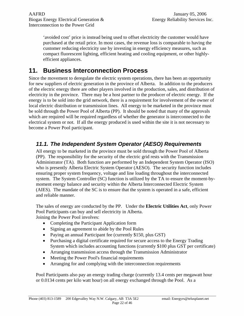
11. Business Interconnection Process Since the movement to deregulate the electric system operations, there has been an opportunity for new suppliers of electric generation in the province of Alberta. In addition to the producers of the electric energy there are other players involved in the production, sales, and distribution of electricity in the province. There may be a host partner to the producer of electric energy. If the energy is to be sold into the grid network, there is a requirement for involvement of the owner of local electric distribution or transmission lines. All energy to be marketed in the province must be sold through the Power Pool of Alberta (PP). It should be noted that many of the approvals which are required will be required regardless of whether the generator is interconnected to the electrical system or not. If all the energy produced is used within the site it is not necessary to become a Power Pool participant.
11.1. The Independent System Operator (AESO) Requirements All energy to be marketed in the province must be sold through the Power Pool of Alberta (PP). The responsibility for the security of the electric grid rests with the Transmission Administrator (TA). Both function are performed by an Independent System Operator (ISO) who is presently Alberta Electric System Operator (AESO). The security function includes ensuring proper system frequency, voltage and line loading throughout the interconnected system. The System Controller (SC) function is utilized by the TA to ensure the moment-by-moment energy balance and security within the Alberta Interconnected Electric System (AIES). The mandate of the SC is to ensure that the system is operated in a safe, efficient and reliable manner. The sales of energy are conducted by the PP. Under the Electric Utilities Act, only Power Pool Participants can buy and sell electricity in Alberta. Joining the Power Pool involves:
• Completing the Participant Application form • Signing an agreement to abide by the Pool Rules • Paying an annual Participant fee (currently $150, plus GST) • Purchasing a digital certificate required for secure access to the Energy Trading
System which includes accounting functions (currently $100 plus GST per certificate) • Arranging transmission access through the Transmission Administrator • Meeting the Power Pool's financial requirements • Arranging for and complying with the interconnection requirements
Pool Participants also pay an energy trading charge (currently 13.4 cents per megawatt hour or 0.0134 cents per kilo watt hour) on all energy exchanged through the Pool. As a
Phone (403) 813-1589 200 Edgevalley Way N.W. Calgary, AB T3A 5E2 email: [email protected] Page 22 of 46

AAFRD January 05, 2006 Biogas Energy Electrical Generation & Energy Reliability Services Inc. Interconnection to the Power Grid
participant in the PP bids and/or offers to trade energy can be made. The PP is accountable to ensure a supply and demand balance on the system and to supply appropriate accounting for suppliers and purchasers. There is opportunity for participants to trade energy through the use of contracts. The Power Pool releases the Participant Specific Offer/Bid Schedules, Day Ahead Forecast, Trading Day Data and Day Ahead Forecast for the next day. All parties producing and selling electrical energy in the province are expected to live up to standards that have been established. The guiding principles of the interested parties are:
• The interconnection process provides competitive, fair and equitable access for all generating parties.
• The interconnection must not create a safety hazard to other customers, the public or operating personnel.
• The interconnection must not compromise the reliability or restrict the operation of the electric system.
• The interconnection does not degrade power quality below acceptable levels.
The energy producer is required to: • Become a power pool participant and comply with any power pool requirements
(unless all energy produced at the site is to be consumed at the site). • Providing technical information to the owner of the distribution or transmission wires,
and to the AESO. This information includes: o General Information:
- A detailed map showing the proposed plan location - A site plan showing the arrangement of the major equipment - Diagram showing the voltage and current rating of each major component
o Technical Information on: - Interconnection protection - The prime mover - The generator including the excitation system - The voltage regulator - Any additional voltage compensation - The transformers - The metering and instrument transformers
o Additional Information: - expected use and distribution of the energy produced - commercial and operating contacts - if the generator is large enough to affect either adjacent customers or the
dynamic stability of the system it is connected to detailed information to allow modeling transient, dynamic and steady-state behavior of the generator.
• Designing, installing, operating and maintaining the interconnection facilities on the producer's side of the interconnection.
• Obtaining all required permits and licenses, which includes: • Ensuring that the local inspection and code enforcement authorities accept the
installation.
Phone (403) 813-1589 200 Edgevalley Way N.W. Calgary, AB T3A 5E2 email: [email protected] Page 23 of 46

AAFRD January 05, 2006 Biogas Energy Electrical Generation & Energy Reliability Services Inc. Interconnection to the Power Grid
• Obtaining an operating agreement with distribution or transmission wire owner covering the technical and operating requirements.
• Obtaining Alberta Energy and Utilities Board approval and order to connect. • Obtaining an agreement on tariffs with the AESO • Obtaining approval from the distribution or transmission wire owner before any
modification is made to the generating customer's system. • Negotiating the timing and any testing requirements for the commissioning process.
All generators connecting to the Alberta grid must be capable of supplying telemetry data to the System Controller in the format and at the frequency deemed to maintain a safe and reliable electric system. The owners of generating plants are responsible for ensuring that all requested metered data is delivered to the Power Pool's communication interface. Currently, generators of less than 5 MW gross output that tie into distribution system voltages will not be required to supply telemetry data. The participant is required to communicate with the System Controller whenever the generator is synchronized or taken off the system. Supplied telemetered data includes:
• Generator MW/MVAR analogs • Generator unit/plant auxiliary loads (MW/MVAR) analogs • Generator breaker status • Breaker status of any other breaker which would separate generator from buss
Geographical location will have an affect on the information requirements of the generator. Existing metering points will negate the need for the generator to supply any redundant information. In addition to supplying energy, a generator may be used to supply system support services (ancillary services). These ancillary services affect the security of the system. The TA is responsible for ensuring adequate levels of ancillary services exist on the system. The opportunity for smaller generators to participate in the provision of ancillary services is limited. For larger generators (500 KW and above) it can provide an additional source of revenues.
11.2. Alberta Energy and Utilities Board (AEUB) Requirements The AEUB is a quasi-judicial provincial agency that regulates the safe, responsible, and efficient development of the province’s energy resources and utilities. They ensure that the development, and delivery of Alberta’s resources take place in a manner that is fair, responsible, and in the public interest. The EUB administer requirement of the Hydro Electric Energy Act with regards to the production and distribution of electricity in the province. The EUB believes that everyone potentially affected - landowners, occupants, local residents, communities, local governments, nongovernment organizations, and companies - must work together throughout the application process and throughout the
Phone (403) 813-1589 200 Edgevalley Way N.W. Calgary, AB T3A 5E2 email: [email protected] Page 24 of 46

AAFRD January 05, 2006 Biogas Energy Electrical Generation & Energy Reliability Services Inc. Interconnection to the Power Grid
project’s life to ensure the public interest is met. They have laid out required public consultation requirements are detailed in the various guides.14
The following information must be included in every application:
• a description of the approval, permit, or license applied for • the grounds on which the application is made • a reference to the act and section under which the application is made • a description of the facts relevant to the application; • a description of the public consultation process; • any other information necessary to provide the EUB with a full and complete understanding of the application • whether there are any outstanding landowner/resident concerns
A biogas facility with generation may require an application to the AEUB for a waste processing and disposal facility, a industrial system designation, and one for the electric power generating plant.
Once the AEUB has the application and is satisfied that all their requirements have been met they will issue a Permit and License for the facilities; and in the case of a generator which is interconnected with the grid will issue a Connection Order.
11.3. Utility Requirements Utility requirements include those of the transmission facilities owner (TFO) and those of the distribution facilities owner (DFO). For the most part the requirement of the utilities is similar to the requirements of the AESO. For lower powered generation interconnections there is little involvement of the TFO. If a significant generation level is reach (at least 10 MW15) or if the generator is of a synchronous type the TFO will want to be involved and may require additional protections such as a transfer tripping scheme from their system substation. The DFO will have a great deal of involvement with any generation that interconnects with their equipment. They will require and Interconnection Agreement, an Operating Agreement, and if there are any facilities to be modified, a Construction Agreement with appropriate payments for the construction. If energy will be taken off the interconnected system to supply loads at anytime they will require the account number with the energy service provider. For the most part the interconnect requirements with the distribution facilities owners including ATCO, FortisAlberta, ENMAX, EPCOR, and others will be the same at a high level. A map showing the Wire Owners geographic service areas is shown in Figure 3 – Wire Owners Geographic Service Areas.
14 EUB Guide 29: Energy and Utility Development Applications and the Hearing Process (January 2003)
15 Customer Interconnections http://www.altalink.ca/Default.aspx?DN=201,196,1,Documents
Phone (403) 813-1589 200 Edgevalley Way N.W. Calgary, AB T3A 5E2 email: [email protected] Page 25 of 46

AAFRD January 05, 2006 Biogas Energy Electrical Generation & Energy Reliability Services Inc. Interconnection to the Power Grid
11.4. Summary of Steps in Generating and Becoming Interconnected 1. Determine what you have for feed stocks on a sustainable basis. 2. Determine the electrical energy that can be produced from the feed stocks. 3. Determine what electrical capacity would be required to produce the expected
energy. 4. Determine what reliability is required. 5. Determine if the plant will be used in a stand alone mode. 6. Determine if there will be energy available in excess of internal requirements. 7. Determine the most effective generating voltage. 8. Determine the most effective electrical configuration. 9. Estimate the expected cost of the configuration and approvals and interconnection
process. 10. Estimate the energy savings or energy exports in dollars. 11. Decide whether to proceed. 12. Obtain an estimate from the DFO of the physical interconnection and any
protection requirement costs from the plant location to their system. 13. Obtain from the DFO what commercial arrangements are required. 14. Obtain from the DFO a project schedule for their components. 15. Obtain from the municipal governmental authority the possibility of getting a
development permit. 16. Apply to the AEUB for a permit, license, and if applicable an interconnection
permit. 17. Determine with Alberta Environment whether a digester permit is required. 18. Apply to the AESO for a Unit ID, to become a pool participant, and obtain
commercial contracts. 19. Contract with a meter service provider. 20. Contract with an energy retailer if load will be taken from the system. 21. Establish operating agreements with the DFO. 22. With appropriate approval and permits in hand contract for construction. 23. Obtain an electrical permit. 24. Construct facilities. 25. Define operating policies, practices, and procedures to meet permit and license
requirements along with equipment manufactures recommendations. 26. Commission unit and interconnection. 27. Contract for and perform routine operating and maintenance functions.
Phone (403) 813-1589 200 Edgevalley Way N.W. Calgary, AB T3A 5E2 email: [email protected] Page 26 of 46

AAFRD January 05, 2006 Biogas Energy Electrical Generation & Energy Reliability Services Inc. Interconnection to the Power Grid
12. Costs and Benefits of Small, Local Generation
12.1. Benefits to society of biogas facilities
12.1.1. Reduction of emissions The Alberta agriculture sector contributes approximately one third of the total agriculture green house gas emissions in Canada and approximately 10% of the total provincial GHG emissions. Digesters can significantly reduce these emissions and provide products that are useful to society. Digested manure contains fewer pathogenic organisms and is less odorous than raw manure. The residual products can be stored and spread on fields without concern for odor and other nuisances. Through the digestion process the potential for harm to water supplies and watercourses is significantly reduced.
The production of electricity using biogas from wastes produced in agricultural production can enhance the competitiveness of the agricultural sectors involved. Additional economic growth can be created and the agricultural sector can be seen as innovative with a real concern for the environment and for waste management.
12.1.2. Generate revenue by selling electricity or gas Biogas can be used to power co-generation units, which produce both heat and electricity. The heat can be used on site for heating buildings and/or the digester. The electricity can be used on site or sold to the grid.
12.1.3. Earn tax credits for renewable energy production As society becomes more aware of green energy production there may be tax credits or even grants available to build renewable facilities. or premiums available for energy produced for biomass based energy.
12.1.4. Sell Green Tags16, or carbon credits, the environmentally beneficial attributes of the renewable energy. As society becomes more aware of green energy production there may premiums available for energy produced for biomass based energy.
12.1.5. Eliminate odor issues. As our rural communities become more densely populated there is less tolerance for odors produced from manure. This issue is greatly reduced with the volatile compounds being “burned” in the digestion/generation process.
16 http://www.green-e.org/what_is/dictionary/trc.html
Phone (403) 813-1589 200 Edgevalley Way N.W. Calgary, AB T3A 5E2 email: [email protected] Page 27 of 46

AAFRD January 05, 2006 Biogas Energy Electrical Generation & Energy Reliability Services Inc. Interconnection to the Power Grid
12.1.6. Earn tipping fee revenue for treating waste. Others in a reasonable proximity to a digester may be willing to pay a fee for the waste disposal service. At the same time these wastes become fuel to substrates while increase methane and electrical production.
12.1.7. Make compost sales revenue The residual products for digestion can be used as low grade fertilizers and have also been used for livestock bedding.
12.1.8. Avoid regulatory penalties for manure management issues. The management of wastes using the digestion process greatly lowers the risk of a violation of environmental legislation. The Fisheries Act has some potential very harsh penalties.
12.1.9. Offset power & heating costs. Production of electricity within the plant operation can reduce or eliminate the risk of the volatility in electricity costs. Within Alberta we have seen typical average energy prices in the range of 5 cents a kwh but recent prices have been in excess of 12 cents per kwh.
12.1.10. Deferral of generation, transmission, and distribution infrastructure Through the interconnection of small local generation, feeding local plant load and/or local distribution system load, society may be able to defer the installation of large centralized generating plants. Transmission lines connecting these centralized generating plants to load centers, or distribution facilities which connect transmission substations to residential, business and small plant facilities may also be deferred. This deferral can lower the cost, which must be borne by the energy users, of installing these facilities.
12.1.11. Potential for increased Reliability If Utilities could become more comfortable with the idea of distribution load being supplied from local generation independent of a connection to the larger grid , a concept known as Islanding, then loads could be supplied under planned or unplanned outage conditions from these “distributed generators”. The major issues are those of safety, power quality and associated liability. The issues of safety and quality can be managed with appropriate practices and standards which for the most part are in place at the present time. The concern for liability can be managed with appropriate contracts or if required, legislation.
12.2. Costs to society There would be few costs to society in getting digester projects going. There may be some costs to governments in facilitating the acceptance and approval of these plants. There could be some costs in tax credits or grants in order to attract developers and facilitate development
Phone (403) 813-1589 200 Edgevalley Way N.W. Calgary, AB T3A 5E2 email: [email protected] Page 28 of 46

AAFRD January 05, 2006 Biogas Energy Electrical Generation & Energy Reliability Services Inc. Interconnection to the Power Grid
of the first few projects. Generally these projects should be self financing. There could be cost to the general public in premium payments for green energy.
12.2.1. Maintain infrastructure The plant infrastructure for the development should be maintained by the developer. The electric system to which the development interconnects will not have additional wear and tear because of the development and as such should not require additional maintenance and as such there should be no additional maintenance costs.
12.2.2. Provide back up supplies For plants which are very large in the order of 300 of 400 Mw there is impact on the system in that there has to be reserves to cover the loss of these large units. The unit sizes proposed with digester/generators is very small and as such will not require backup supplies. These units are essentially hidden in the load noise (constant changes in capacity required by loads) on the system and as such should not be a cost to society.
12.3. Benefits to the developer • Eliminates odor • Reduces or eliminates pathogens from waste stream • Production of a low grade fertilizer • Generates revenue or reduces costs through the production of electricity and heat. • The potential to produce revenues from greenhouse gas emissions offsets • Potential to generate revenue from residual products • Reduction of the potential for harm to water courses • Prevents regulatory penalties for waste treatment
12.3.1. Stand alone plant for local use Biogas can be used to power co-generation units, which produce both heat and electricity. The heat can be used on site for heating buildings and/or the digester. The electricity can be used on site or sold to the grid.
12.3.2. For sales to the Interconnected System With Agriculture accounting for 10% of Alberta’s greenhouse gas contribution, if biogas electricity production can get green tag certifications there can be a significant financial contribution to the owner of the energy facility.
13. A Sample Economic Evaluation
13.1. Interconnection Examples
13.1.1. Typical Load Supply Reference Drawing: Typical Load Supply Dwg. 01
Phone (403) 813-1589 200 Edgevalley Way N.W. Calgary, AB T3A 5E2 email: [email protected] Page 29 of 46

AAFRD January 05, 2006 Biogas Energy Electrical Generation & Energy Reliability Services Inc. Interconnection to the Power Grid
The typical supply consists of a 25 kV fused disconnect, a transformer, a revenue meter and a connection to the customers service. The meter will typically be a normal kwh meter with a demand indicator. On first connection the customer would be asked for a capital contribution and then be charged for Delivery Charges and Energy Charges. The amount of contribution is dependent on the Wire Owners investment policy17. Delivery (Demand) charges consist of a Fixed Cost of 12.61 per month, a Variable Cost of 0.72 cents per KWh and a Demand Cost of $4.29 per KVA. Energy Charges consist of the Cost of energy - 4.93 cents per KWh and an Energy Administration Charge - $0.62 per KWh18. The transformer size shown restricts the maximum load to 500 kVA.
17 Policy is available from the wire owners and specific investment amounts are determined on an application basis
18 Specific rates are available from energy providers or from wire owners.
Phone (403) 813-1589 200 Edgevalley Way N.W. Calgary, AB T3A 5E2 email: [email protected] Page 30 of 46

AAFRD January 05, 2006 Biogas Energy Electrical Generation & Energy Reliability Services Inc. Interconnection to the Power Grid
Typical Load Supply Dwg. 01
25 kV 3 Phase Power Line
Fused Disconnect
MotorBreakers
M
75 hp
BKR 600 V Switchgear
M
xx hp
Metering Ct's & PTsM
OutdoorMounted
Typical Load SupplyDwg. 01
Demand = 250 kw500 kva25000/600 V
Revenue Metering
xxx kva600/120/ V
Local Loads
Utility Supply
Note: Transformer sizes and configurations are application specific
Phone (403) 813-1589 200 Edgevalley Way N.W. Calgary, AB T3A 5E2 email: [email protected] Page 31 of 46

AAFRD January 05, 2006 Biogas Energy Electrical Generation & Energy Reliability Services Inc. Interconnection to the Power Grid
13.1.2. Generation Plant via Existing Load transformer Supply Reference Drawing: Generation Plant via Existing Load Transformer Dwg. 02. The generator(s) will be directly connected via breakers to the customers load bus. The maximum power flow to or from the utility is 500 kVA, the interconnection transformer size. The generator(s) size can be up to the sum of the transformer size and the load, in this case 750 kVA (500 kVa transformer and 250 kVA load. The interconnection protection would normally be provided by over/under voltage and over/under frequency functions in the Generator MF (multi-function) Relay and the Transformer MF (multi-function) Relay. The revenue metering would currently need to be changed to an Interval Meter. Note: This would be an idea application for net metering. This would allow maxim flexibility for operating the Biogas plant and the local load without having the additional costs of becoming a full generator. In this application if a synchronous generator is applied, the entire local and plant load can be supplied without a connection to the distribution system if the WO system is not available due to maintenance or trouble. This is can accomplished through relay logic or manually by opening the interconnecting breaker (BKR In).
Phone (403) 813-1589 200 Edgevalley Way N.W. Calgary, AB T3A 5E2 email: [email protected] Page 32 of 46

AAFRD January 05, 2006 Biogas Energy Electrical Generation & Energy Reliability Services Inc. Interconnection to the Power Grid
Generation Plant via Existing Load Transformer Dwg. 02 25 kV 3 Phase
Power Line
Fused Disconnect
MotorBreakers
M
75 hp
BKR In600 V Switchgear
M
xx hp
Metering Ct's& PTs
M
GS
300 kva600 V
GS
300 kva600 V
600 V Swgr
High Side Isolating Switch
Point of Delivery
MF Transformer Protection
Relay
Generation Plant via Existing Load Transformer
Dwg. 02
Plant Loads
Gen. MF Relay
Gen. MF Relay
Demand = 250 kw500 kva25000/600 V
Revenue Metering
Local Loads
xxx kva600/120/ V
Generator Supplier
Size and Number of Generators Site
Specific
Utility Supply
Note: Transformer sizes and configurations are application specific
Phone (403) 813-1589 200 Edgevalley Way N.W. Calgary, AB T3A 5E2 email: [email protected] Page 33 of 46

AAFRD January 05, 2006 Biogas Energy Electrical Generation & Energy Reliability Services Inc. Interconnection to the Power Grid
13.1.3. Generation Plant via Step – Up Transformer Reference Drawing: Generation Plant via Step Up Transformer Dwg. 03. The generator(s) will be directly connected via breakers to a step up transformer to the utility system. The local and plant load is supplied from the generator bus via a transformer sized to meet the load requirements. The maximum power flow to or from the utility would be determined by the generation available minus the local load. The interconnecting transformer would be sized to meet the net generating export to the grid. The interconnection protection would normally be provided by over/under voltage and over/under frequency functions in the Generator MF (multi-function) Relay and the Transformer MF (multi-function) Relay. In this application additional Interconnection Protection may be required depending of distribution feeder capacity and loads. This is normally provided by addition relaying like “Vector Jump” protection or “Transfer Tripping” via communications. The revenue metering would currently need to be an Interval Meter. This size of interconnection would typically require the generator to become a full member of the Power Pool and all its associated requirements. This configuration would also allow maxim flexibility for operating the Biogas plant and the local load. In this application if a synchronous generator is applied, the entire local and plant load can be supplied without a connection to the distribution system if the WO system is not available due to maintenance or trouble. This can accomplished through relay logic or manually by opening the interconnecting breaker (BKR In).
Phone (403) 813-1589 200 Edgevalley Way N.W. Calgary, AB T3A 5E2 email: [email protected] Page 34 of 46

AAFRD January 05, 2006 Biogas Energy Electrical Generation & Energy Reliability Services Inc. Interconnection to the Power Grid
Generation Plant via Step Up Transformer Dwg. 03 25 kV 3 Phase
Power Line
Fused Disconnect
MotorBreakers
M
75 hp
BKR600 V Switchgear
M
xx hp
GS
770 kw960 kva4160 V
GS
770 kw960 kva4160 V
4160 V Swgr
2000 kva25000/4160V
High Side Isolating Switch
Revenue Metering Metering CT’s & PT’s M
Point of Delivery
Fused Disconnect
MF Transformer Protection
Relay
Generation Plant via Step Up Tx’er
Dwg. 03
Cable or Overhead
xxx kva4160/600 V
Plant Loads
Gen. MF Relay
Gen. MF Relay
Local Loads
xxx kva600/120/ V
Generator Supplier
Size and Number of Generators Site
Specific
Utility Supply
Note: Transformer sizes and configurations are application specific
BKR In
Phone (403) 813-1589 200 Edgevalley Way N.W. Calgary, AB T3A 5E2 email: [email protected] Page 35 of 46
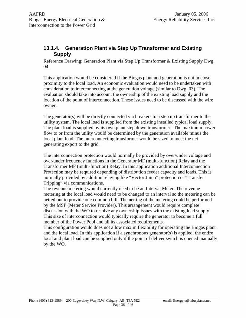
AAFRD January 05, 2006 Biogas Energy Electrical Generation & Energy Reliability Services Inc. Interconnection to the Power Grid
13.1.4. Generation Plant via Step Up Transformer and Existing Supply
Reference Drawing: Generation Plant via Step Up Transformer & Existing Supply Dwg. 04. This application would be considered if the Biogas plant and generation is not in close proximity to the local load. An economic evaluation would need to be undertaken with consideration to interconnecting at the generation voltage (similar to Dwg. 03). The evaluation should take into account the ownership of the existing load supply and the location of the point of interconnection. These issues need to be discussed with the wire owner. The generator(s) will be directly connected via breakers to a step up transformer to the utility system. The local load is supplied from the existing installed typical load supply. The plant load is supplied by its own plant step down transformer. The maximum power flow to or from the utility would be determined by the generation available minus the local plant load. The interconnecting transformer would be sized to meet the net generating export to the grid. The interconnection protection would normally be provided by over/under voltage and over/under frequency functions in the Generator MF (multi-function) Relay and the Transformer MF (multi-function) Relay. In this application additional Interconnection Protection may be required depending of distribution feeder capacity and loads. This is normally provided by addition relaying like “Vector Jump” protection or “Transfer Tripping” via communications. The revenue metering would currently need to be an Interval Meter. The revenue metering at the local load would need to be changed to an interval so the metering can be netted out to provide one common bill. The netting of the metering could be performed by the MSP (Meter Service Provider). This arrangement would require complete discussion with the WO to resolve any ownership issues with the existing load supply. This size of interconnection would typically require the generator to become a full member of the Power Pool and all its associated requirements. This configuration would does not allow maxim flexibility for operating the Biogas plant and the local load. In this application if a synchronous generator(s) is applied, the entire local and plant load can be supplied only if the point of deliver switch is opened manually by the WO.
Phone (403) 813-1589 200 Edgevalley Way N.W. Calgary, AB T3A 5E2 email: [email protected] Page 36 of 46

AAFRD January 05, 2006 Biogas Energy Electrical Generation & Energy Reliability Services Inc. Interconnection to the Power Grid
Generation Plant via Step Up Transformer & Existing Supply Dwg. 04 25 kV 3 Phase
Power Line
Fused Disconnect
MotorBreakers
M
75 hp
BKR600 V Switchgear
M
xx hp
Metering Ct's& PTs
M
GS
770 kw960 kva4160 V
GS
770 kw960 kva4160 V
4160 V Swgr
2000 kva25000/4160V
High Side Isolating Switch
Revenue Metering Metering CT’s & PT’s M
Point of Delivery
Fused Disconnect
MF Transformer Protection
Relay
Generation Plant via Step Up Tx’er & Existing Supply
Dwg. 04
Cable or Overhead
xxx kva4160/600 V
Plant Loads
Gen. MF Relay
Gen. MF Relay
Demand = 250 kw500 kva25000/600 V
Revenue Metering
Local Loads
xxx kva600/120/ V
Generator Supplier
Size and Number of Generators Site
Specific
Utility Supply
Note: The 2 Revenue Metering Points can be summed to create one virtual metering point
BKR In
Note: Transformer sizes and configurations are application specific
Phone (403) 813-1589 200 Edgevalley Way N.W. Calgary, AB T3A 5E2 email: [email protected] Page 37 of 46

AAFRD January 05, 2006 Biogas Energy Electrical Generation & Energy Reliability Services Inc. Interconnection to the Power Grid
13.2. Sample Costs The interconnection costs range can range from $ 60,000 to $350,000. A table of the various interconnection options is presented for illustrative purposes. With the various interconnection options available, anyone considering development of a generation facility intended for interconnection to a distribution system should engage the services of individuals qualified to provide design and consulting services for electrical interconnection facilities. These consultants can be hired for approximately $2000 to $10,000 to provide a technical and cost analysis of the options.
Interconnections Cost Table
Reference Dwg. 02 DWG. 03 Dwg. 04 Item Material Item Cost $ Cost $ Cost $
1 O/H 25 kV LINE Assume 1 km @ $40,000/km installed
40,000.00 40,000.00
2 25 kV Power Cables. Assume $25/meter for single phase cable Assume 1 km - $25/m x 1000m x 3 phases
75,000.00 75,000.00
3 25 KV Terminal Structures 3,000.00 3,000.00 4 HV Terminations 1,500.00 1,500.00 5 25 kV Fused Disconnect Switch 3,000.00 3,000.00 6 21KV Arrestors 500.00 500.00 7 2 MVA Transformer 40,000.00 40,000.00 8 600 volt Switchgear 2,000.00 9 4160V Switchgear including Breaker & Fused Disconnect 50,000.00 50,000.00
10 3 x Metering CTs 6,000.00 6,000.00 11 3 x Metering PTs 6,000.00 6,000.00 12 Switchgear CT's & PT's 10,000.00 10,000.00 13 500 KVA Transformer 12,000.00 12,000.00 14 4160 V Power Cables 15,000.00 15,000.00 15 600 V Cables 3,000.00 1,000.00 1,000.00 16 Control Cables 1,500.00 2,000.00 2,000.00 17 DC Battery Bank 4,000.00 4,000.00 4,000.00 18 Ground Grid 1,000.00 1,000.00 1,000.00 19 Transformer Protection Relays 10,000.00 22,000.00 22,000.00 20 Revenue Meter 8,000.00 8,000.00 16,000.00 21 Panel for Relay & Revenue metering 10,000.00 10,000.00 10,000.00 22 Interconnection Relays 12,000.00 12,000.00 23 Transfer Trip Term. Equipment 25,000.00 25,000.00 24 Radio Communications 20,000.00 20,000.00 25 Misc Equipment 2,000.00 10,000.00 10,000.00 26 Foundations 8,000.00 8,000.00
27 Construction Equipment (Cranes, bobcat, Trenching, etc) 1,000.00 10,000.00 10,000.00
Phone (403) 813-1589 200 Edgevalley Way N.W. Calgary, AB T3A 5E2 email: [email protected] Page 38 of 46

AAFRD January 05, 2006 Biogas Energy Electrical Generation & Energy Reliability Services Inc. Interconnection to the Power Grid
28 Total Material 42,500.00 280,000.00 288,000.00
29 Labor Item 30 Consulting Engineer 2,000.00 5,000.00 5,000.00 31 Engineering/Design/Drafting 6,000.00 25,000.00 25,000.00 32 Construction Site 5,000.00 20,000.00 20,000.00 33 Commissioning / Testing 5,000.00 7,000.00 7,000.00
34 Total Labor 18,000.00 57,000.00 57,000.00 45 GRAND TOTAL $ 60,500.00 $ 337,000.00 $ 345,000.00
Assumptions: 36 Building Space is available for switchgear and protection panels 37 Cost Totals assume OH Line (Item1). Item 2 costs not included 38 Material Items 22 & 23 are not included in the costs as they are specific application dependent and are
probably not required.
14. Barriers / Gaps identification. • Perhaps the number one interconnection barrier for small renewable systems has been the
lack of simplicity and understanding of the interconnection standards. This is a result of the traditional discretion given to utilities to deal with their own generation, transmission, and distribution systems. To be more accurate, it is a problem of many utilities not having any standards at all for small grid-tied generators. In the case where a utility has no small generator standards, interconnection is addressed on either a case-by-case basis or through existing standards usually used for larger industrial systems. However, it is beyond the means of most prospective residential or small commercial system owners to hire a professional engineer and attorney for the interconnection of a small grid-tied system that is intended simply to offset a portion of the owner’s electricity use.
• From the wire owner’s perspective there is a great deal of work with little reward. DFO’s do
not trust the DG’s to maintain and make easy access available for isolating devices. • DFO’s typically operate the system voltage at the upper limit (approximately 104%)of the
nominal voltage of 25 kV. The required overvoltage protection settings are required to be set at 106% for short time frames. When the transmission system voltage or distribution system voltage changes by 2 %, false trip operations are encountered by the interconnecting generator. DFO’s should consider operating there systems at the nominal voltage of 25 kV,
Phone (403) 813-1589 200 Edgevalley Way N.W. Calgary, AB T3A 5E2 email: [email protected] Page 39 of 46

AAFRD January 05, 2006 Biogas Energy Electrical Generation & Energy Reliability Services Inc. Interconnection to the Power Grid
allow the overvoltage trip setting to be at a higher level or allow a longer time delay before the protection is required to operate. The DFO starts from a position that there system is always correct and places the emphasis back on the DG’s to prove that the voltage is being operated at to high a level. This takes time and effort and most DG’s require technical assistance to help in establishing this burden of proof.
• Many electrical and building inspectors are not familiar with interconnection issues, and may
be reluctant to approve some installations. Once standards have been harmonized, there should be a significant effort to inform front-line workers throughout the industry.
• Wire owners will normally try to place independent devices controlled only by them as part
of the interconnection proposal. Devices like visual break switches and breakers are normally duplicated at the DG’s facilities. This is duplication of functionality and increases the cost of the interconnection.
• Biogas contains hydrogen sulphide that must be removed as much as possible before
reaching the gas processing equipment. • There is no current standard meter that is Measurements Canada approved for Net Metering.
Net metering is currently provided through the use of 2 back to back meters.
15. Conclusions and Recommendations • The deregulation of the electricity sector in Alberta provides an opportunity to establish
guidelines and policies that will support the widespread use of small renewable energy power and distributed generation sources. Initiatives that are aimed at increasing the market for small renewable and distributed generation require the support of governments because of:
o new technologies often offer cost-effective and efficient solutions with significant environmental benefits;
o there is a huge market potential worth billions of dollars and thousands of jobs; and o distributed generation improves the reliability of electricity power at the site and
delays infrastructure upgrades to the existing network. • Government should establish a regulation that would permit "net metering". Net metering
would give credit to customers who generate their own power from renewable sources such as such as water, wind, solar power and farm biomass. The new regulation should require that distributors permit net metering for all eligible projects that produce up to 1000 kilowatts.
• Generally, the aggregate amount of generation that can be easily interconnected on any single distribution line is approximately 1/3 of the minimum load on the distribution line.
• Based on recent power prices in Alberta, power from biomass could be supported by carbon credits as low as $5 to $10 per tonne of CO2, which is very competitive with other options for reducing carbon impact from fossil fuel.
Phone (403) 813-1589 200 Edgevalley Way N.W. Calgary, AB T3A 5E2 email: [email protected] Page 40 of 46

AAFRD January 05, 2006 Biogas Energy Electrical Generation & Energy Reliability Services Inc. Interconnection to the Power Grid
• Anyone considering development of a generation facility intended for interconnection to a distribution system should engage the services of individuals qualified to provide economic, design and consulting services for electrical interconnection facilities.
• When making a decision to invest in a digester/generation operation a great deal of care must be taken in estimating how much energy and therefore revenues of cost reduction will be achieved. There was a great deal of conflicting information in the market place. The estimates appearing in this report are on the conservative side relative to the information available.
• Lethbridge County would provide a good opportunity for a prototype biogas generation operation. If the a digester could be co located with a food processing operation the heat requirements of the food processor may be met with the residual heat (about equivalent to the electrical energy production) from the digestion/generation process.
• Since it is difficult for an individual developer to interface with the numerous governmental groups involved, it would be beneficial if one of these governmental groups would take a lead role in establishing the relationships and process requirements that would assist a developer in moving forward with building a facility.
• DFO’s should be encouraged to review there voltage operating practices and interconnection protection requirements to allow DG’s to operate without unnecessary false trip operations.
• Measurements Canada should be encouraged to approve a standard meter for use as a Net Meter as soon as practical.
Phone (403) 813-1589 200 Edgevalley Way N.W. Calgary, AB T3A 5E2 email: [email protected] Page 41 of 46

AAFRD January 05, 2006 Biogas Energy Electrical Generation & Energy Reliability Services Inc. Interconnection to the Power Grid
15. References
1) Alberta Distributed Generation Interconnection Guide 2) ATCO Electric- standard for the Interconnection of Generators to ATCO Electric’s
Distribution system-Application Notes 3) ENMAX Power Corporation – Guide for Generator Interconnection to the Wire Owner
Distribution System 4) IEEE 1547-2003 IEEE Standard for Interconnecting Distributed Resources with Electric
Power Systems 5) Guide 29 Energy and Utility Development Applications and the Hearing Process January
2003 6) MANURE MANAGEMENT AND GREENHOUSE GAS MITIGATION
TECHNIQUES: Climate Change Central DISCUSSION PAPER C3 – 013 Prepared by: Chris Langmea
7) AESO “FUTURE DEMAND AND ENERGY REQUIREMENTS (Period: 2004 – 2024) Document: FC-2004-1 June 2004
16. Biographies
16.1. Stan C. Gordeyko, P.Eng. Stan C. Gordeyko P.Eng. was born and raised in rural Alberta and received a B.Sc. degree in Electrical Engineering from the University of Alberta in 1971. He attended the Executive Development Program, University of Calgary, in Calgary, Alberta in 1988. He is registered to practice in Alberta and Ontario and is a member of the IEEE Power Engineering Society. Stan has been involved in the Electric Utility Business for 30 years working for Ontario Hydro, Nigerian Electric Power Authority and Calgary Power/TransAlta Utilities in numerous technical and management positions. He is currently a principal in “Energy Reliability Services Inc” and is working with “High Time Industries Ltd” a company specializing in high voltage electrical substations and generation interconnections. Stan has been involved in numerous generation interconnections to the utility power grids. These include 50 kW to 4 MW biogas plants; wind generators from single 660 kW generators to 75 MW wind farms; steam turbine generators from 7 MW to 70 MW, coal fired generators up to 400 MW and numerous gas fired generators from 2 MW to 200 MW. Stan is very interested in renewable energy and is working to ensure small renewable energy sources can be economically and simply interconnected to existing power systems.
Phone (403) 813-1589 200 Edgevalley Way N.W. Calgary, AB T3A 5E2 email: [email protected] Page 42 of 46

AAFRD January 05, 2006 Biogas Energy Electrical Generation & Energy Reliability Services Inc. Interconnection to the Power Grid
16.2. Allen L. Rothbauer, P.Eng. Allen Rothbauer was born in Calgary, Alberta in 1948. He has lived in Calgary all of his life, is married and has two adult sons. He attended the University of Calgary where he attained a B.Sc. in Electrical Engineering in 1971. He went on to attain a B.A. in Economics from the University of Calgary in 1979. He is a Professional Engineer in the province of Alberta. Allen was employed with TransAlta Utilities (formerly Calgary Power Limited) until his retirement in 1999. Within TransAlta he held various roles in their operations groups including Manager of the System Control Centre and Manager of Hydro Operations. Allen is currently President of an independent consulting Company, ARC Services Ltd., which he founded in 2000. Allen is presently working with AltaLink assisting with project specifications of interconnection requirements for both loads and generators to the AIES transmission system. He is very familiar with all aspects of system and generation operation requirements. He has been involved in the interconnection of several small generators into the AIES on both the technical and business arrangements. Allen is very committed to assist individuals and businesses to find opportunities to gain from the deregulated power market.
Phone (403) 813-1589 200 Edgevalley Way N.W. Calgary, AB T3A 5E2 email: [email protected] Page 43 of 46

AAFRD January 05, 2006 Biogas Energy Electrical Generation & Energy Reliability Services Inc. Interconnection to the Power Grid
FIGURE 1 - ELECTRIC TRANSMISSION SYSTEM INPROXIMITY TO THE COUNTY OF LETHBRIDGE
Phone (403) 813-1589 200 Edgevalley Way N.W. Calgary, AB T3A 5E2 email: [email protected] Page 44 of 46

AAFRD January 05, 2006 Biogas Energy Electrical Generation & Energy Reliability Services Inc. Interconnection to the Power Grid
FIGURE 2 – MANURE PRODUCTION INDEX FOR ALBERTA
Phone (403) 813-1589 200 Edgevalley Way N.W. Calgary, AB T3A 5E2 email: [email protected] Page 45 of 46

AAFRD January 05, 2006 Biogas Energy Electrical Generation & Energy Reliability Services Inc. Interconnection to the Power Grid
FIGURE 3 – Wire Owners Geographic Service Areas
Phone (403) 813-1589 200 Edgevalley Way N.W. Calgary, AB T3A 5E2 email: [email protected] Page 46 of 46