Embed Size (px)
Citation preview
Fracture and strain rate behavior of airplane fuselagematerials under blast loading
J. Mediavilla Varas1,a, F. Soetens2, E. Kroon1, J.E. van Aanhold2, O.R. van der Meulen1, and M.Sagimon1
1 TNO-Defense Security and Safety, Rijswijk, The Netherlands2 TNO Built Environment and Geosciences, Delft, The Netherlands
Abstract. The dynamic behavior of three commonly used airplane fuselage materialsis investigated, namely of Al2024-T3, Glare-3 and CFRP. Dynamic tensile tests using aservo-hydraulic and a light weight shock testing machine (LSM) have been performed.The results showed no strain rate effect on Al2024-T3 and an increase in the failure strainand failure strength of Glare-3, but no stiffening. The LSM results on CFRP were in-conclusive. Two types of fracture tests were carried out to determine the dynamic crackpropagation behavior of these materials, using prestressed plates and pressurized barrels,both with the help of explosives. The prestressed plates proved to be not suitable, whereasthe barrel tests were quite reliable, allowing to measure the crack speeds. The tougher,more ductile materials, Al2024-T3 and Glare-3, showed lower crack speeds than CFRP,which failed in a brittle manner.
1 Introduction
Triggered by the growing terrorist threat, the EU VULCAN project [1] aims at strengthening airbornestructures under blast and fire. Within this framework, TNO’s mission is to investigate the behaviorof airplane fuselage materials under blast loading. An explosion is a highly dynamic event and thefuselage material behaves in a different manner as compared to a static load; stress waves, inertia,temperature and strain rate effects take place. An experimental-numerical research has been setup,focusing on two aspects: dynamic strength and fracture behavior. Three typical airplane fuselage ma-terials have been studied: Aluminum 2024T3, Glare-3, CFRP.
The aim is of this paper is to characterize the dynamic behavior of these type of materials, in orderto better understand their behavior and hence optimize the design of structures against blast of othertypes of dynamic loading events.
2 Dynamic tensile tests
High strain rate tests have been performed using two different two different test machines:
1. A servo-hydraulic high-speed single shot test machine.2. A so-called lightweight shock testing machine (LSM).
The servo-hydraulic test machine was used in [2,3] to measure the dynamic properties of S2 glassfibers, Glare-3 and Al2024-T3. Stresses are directly computed from the measured force, and the strainand strain rates are obtained from digital processing of high speed camera images. The LSM, on theother hand, is normally used for verifying equipment’s resistance to underwater shock induced deck
a e-mail: [email protected]
© Owned by the authors, published by EDP Sciences, 2010DOI:10.1051/epjconf/20100642017EPJ Web of Conferences 6, 42017 (2010) 6
This is an Open Access article distributed under the terms of the Creative Commons Attribution-Noncommercial License 3.0, which permits unrestricted use, distribution, and reproduction in any noncommercial medium, provided the original work is properly cited.
Article disponible sur le site http://www.epj-conferences.org ou http://dx.doi.org/10.1051/epjconf/20100642017
EPJ Web of Conferences
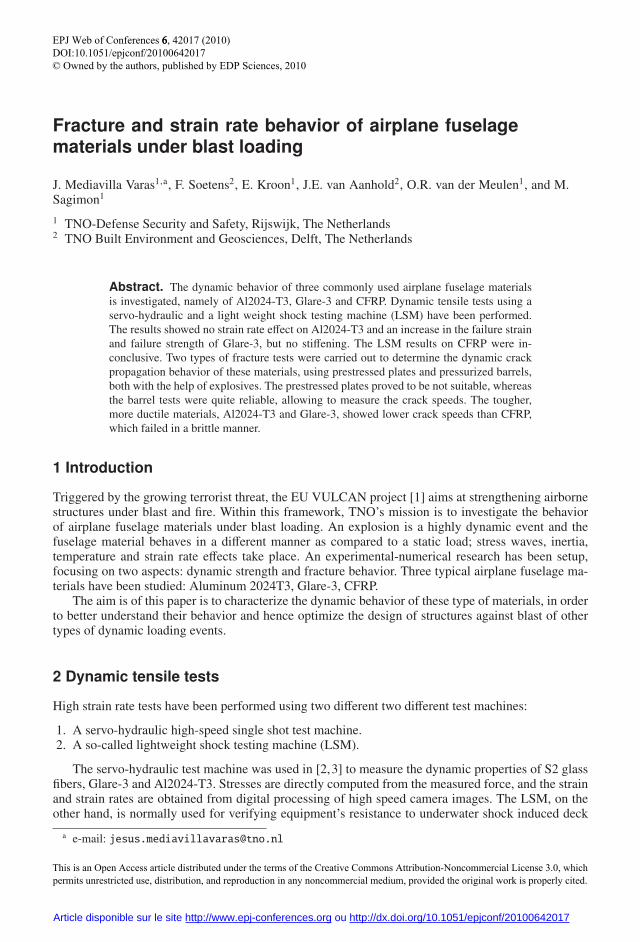
motions on board of naval ships. Stresses are computed from the mass and the acceleration of the clumpmass and strains are measured by means of strain gauges. The servo-hydraulic setup is preferred to theLSM, since it allows to reach higher strain rates, up to 1000 1/s, and the tests are very reproducible,with less dynamic oscillations. On the other hand, the LSM allows for testing substantially largerspecimens, for example structural details, at dynamic loading rates [4]. Fig. 1 shows the two setups.
Fig. 1. (left) servo-hydraulic high-speed machine setup; (middle) sample and high speed camera; (right) LSMsetup.
2.1 Aluminum 2024T3
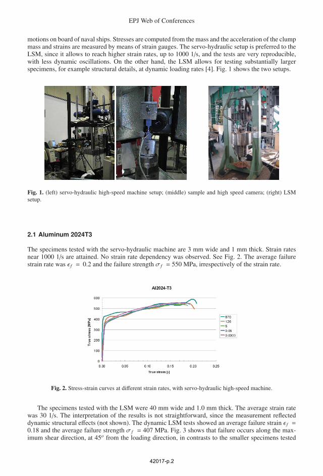
The specimens tested with the servo-hydraulic machine are 3 mm wide and 1 mm thick. Strain ratesnear 1000 1/s are attained. No strain rate dependency was observed. See Fig. 2. The average failurestrain rate was ε f = 0.2 and the failure strength σ f = 550 MPa, irrespectively of the strain rate.
Fig. 2. Stress-strain curves at different strain rates, with servo-hydraulic high-speed machine.
The specimens tested with the LSM were 40 mm wide and 1.0 mm thick. The average strain ratewas 30 1/s. The interpretation of the results is not straightforward, since the measurement reflecteddynamic structural effects (not shown). The dynamic LSM tests showed an average failure strain ε f =0.18 and the average failure strength σ f = 407 MPa. Fig. 3 shows that failure occurs along the max-imum shear direction, at 45o from the loading direction, in contrasts to the smaller specimens tested
42017-p.2

with the servo-hydraulic machine, which failed in the direction perpendicular to the loading direction.Note that the specimen geometries and hence the stress states and the failure modes are different.Hollow specimens, with a hole diameter of 5 mm, were also tested to show the effect of high stresstriaxialities on reducing the failure strain. This was indeed confirmed by experiments, which showed alower failure strength and strain, σ f = 279 MPa and ε f = 0.017 respectively. The hollow specimensfailed in the normal to the loading direction.
Fig. 3. Aluminum specimens after failure, using LSM machine.
2.2 Glare
Static and dynamic tests on Glare specimens were performed using the the servo-hydraulic high-speedand the LSM machine. Two types of Glare were tested with the servo-hydraulic machine: Glare 3-2/1-0.3, 1.1 mm thick; and Glare 3S-3/2-0.3, 2.0 mm thick. The stacking sequence was Al/0/90/Al andAl/0/90/90/0/Al/0/90/90/0/Al respectively. The specimens were 3 mm wide. Fig. 5 shows the stress-strain curve for the Glare 3S-3/2-0.3 specimens.The maximum strain rate reached for Glare 3-2/1-0.3and Glare 3S-3/2-0.3 equals approximately 500 1/s and 300 1/s respectively. Due to the contribution ofthe S2-glass fibers, which are highly strain rate sensitive, significant improvement in straining capacityis seen for Glare 3 with increasing strain rates. Consequently, a significant strength increase is obtainedfor higher strain rates. No strain rate effect is observed in the yield stress and stiffness. Table 1 reportsthe failure strain and failure strength at different strain rates. The LSW Glare specimens were Glare3-3/2-0.5, 2.0 mm thick, with a Al/0/90/Al/90/0/Al stacking. For the same reasons as argued for theAluminum tests, servo-hydraulic tests are preferred (stress-strain curves are not shown). Fig. 5 servesto illustrate how failure occurs, normal to the loading direction, and with delamination of the differentlayers.
ε̇ 0.001 0.01 0.1 1 10 100 200 300 500 1000ε f (%) 4.4 4.4 4.6 5.2 5.7 6.3 6.5 6.6 6.7 6.9σ f (MPa) 814 814 880 966 1054 1142 1169 1185 1204 1231
Table 1. Failure strain and failure strength versus strain rate. Glare 3S-3/2-0.3.
42017-p.3

EPJ Web of Conferences
Fig. 4. Stress-strain curves obtained with servo-hydraulic high-speed machine.
Fig. 5. Glare specimens after failure, using LSM machine.
2.3 CFRP
Tensile tests on CFRP were performed using the LSM machine. The specimens are 40 mm wide and 2mm thick, made of 10 layers [+/-45,0/90,90/0,+/-45,0/90]. The material used is T300 3k PW (E-765).The average strain rate was only 10 1/s. Fig. 6 shows that in contrasts with Glare and aluminum, whichare ductile materials and fail at the middle of the specimen, failure of CFRP may happen at differentlocations, due to the wave propagation. The stress-strain results of these tests are difficult to interpret(not shown) and is recommended to perform servo-hydraulic high-speed tests in the future.
3 Dynamic fracture experiments
Two types of fracture experiments have been performed:
1. Prestressed plate tests.Flat plates of dimensions 800-1600 (w-l) were prestressed at different stress levels, 100 and 200N/mm2. Crack propagation was triggered by creating a notch (200 mm long) in the middle of theplate, by means of an explosive charge. Crack propagation was recorded using high speed camerarecordings, which allowed to compute the crack speed. It turned out that this setup was not suitablefor studying crack propagation for a number of reasons: unknown extent of the damage near theexplosive charge, out of plane movement of the plates due to the explosive load; asymmetric crackpropagation. Fig. 7 shows the hydraulic used in the prestressed plate tests, and some snapshotsduring mode-I crack propagation of the Aluminum, Glare and CFRP specimens.
42017-p.4

Fig. 6. Specimens after failure, using LSM machine.
2. Pressurized barrel tests.In the barrel tests, a barrel with a prenotch (56 mm long) is pressurized, and crack propagation istriggered by the explosion of a TNT charge placed inside, in the middle of the barrel. The barreldimensions are: 1.2 m by 1 m (diameter x height). The top and bottom of the barrel are made ofmassive steel plates, which are firmly fixed relative to one another in the vertical direction. Theskin of the barrel is fixed to the end plates with bolts. The explosive charge is spherical and has amass of 54 gr. To simulate flying conditions, the barrel was pressurized at 200 kPa. The prenotchis taped off to avoid depressurization. Upon pressurization, the explosive is detonated, triggeringcrack propagation.
Fig. 7. (left) prestressed plate setup; (right) high speed camera snapshots during crack propagation for Aluminum(above), Glare (middle) and CFRP (below).
Fig. 9, Fig. 10 and Fig. 11 show the barrel after the explosion, a close-up of the crack and thecrack speed versus crack length for the Aluminum, Glare and CFRP barrels respectively. Aluminumand Glare failed in a ductile manner, with cracks perpendicular to the maximum hoop stress (mode-I),and relatively low crack speeds. The average crack speeds were 300 m/s and 200 m/s for aluminumand Glare respectively. This agrees with the higher toughness of Glare. CFRP shows brittle facture,manifested by a very high crack speed, 2500 m/s, crack bifurcation and zig-zagging.
The lowest and highest crack speeds were found for Glare and the CFRP respectively, since theseare the toughest and the most brittle materials. These experiments have been used to validate and im-
42017-p.5

EPJ Web of Conferences
Fig. 8. (left) sketch of barrel test set-up; (right) photograph of barrel test set-up.
(a) (b)
(c)
Fig. 9. (a) aluminum barrel after explosion; (b) high speed camera snapshots during crack propagation; (c) crackspeed versus crack length.
42017-p.6

(a) (b)
(c)
Fig. 10. (a) Glare barrel after explosion; (b) high speed camera snapshots during crack propagation; (c) crackspeed versus crack length.
prove existing finite element fracture models (cohesive models) [5]. By an inverse modeling technique,it was shown that the fracture toughness increases under dynamic conditions.
4 Conclusions
To characterize the mechanical behavior of airplane fuselage materials (Al2024-T3, Glare-3, CFRP)under dynamic loading, dynamic tensile tests and fracture tests have been performed. The main con-clusions are summarized below.
– Dynamic tensile tests.1. AL2024T3 shows no strain rate effect, constant failure strain and failure strength upon different
strain rates. Glare-3 shows an increase in failure strain and failure strength at high strain rates,while the stiffness and yield stress remain constant. The CFRP tests with the LSM machinewere inconclusive and further experiments must be done.
2. The servo-hydraulic tests are preferred over the LSM tests, since the corresponding equipmentproduces excellent and highly repeatable results without superimposition of stress waves. Fur-thermore, higher strain rates can be attained in comparison with the LSM testing method.
– Dynamic crack propagation tests.1. The prestressed plate tests prove not to be suitable for monitoring crack propagation, due to a
lack of symmetry, undesirable effects caused by the explosive charge (out of plane displace-ment and unknown extent of damage around the crack tips).
2. The barrel tests on the other hand allow to monitor the mode-I crack propagation and mea-sure the crack speed of the different material tested, and it is very useful in order to validatenumerical dynamic fracture models.
42017-p.7

EPJ Web of Conferences
(a) (b)
(c)
Fig. 11. (a) CFRP barrel after explosion; (b) high speed camera snapshots during crack propagation; (c) crackspeed versus crack length.
3. Glare and Aluminum displayed a ductile behavior during crack propagation, while CFRP con-firmed its brittle behavior.
Acknowledgments
The authors would like to acknowledge the partners of the EU project VULCAN and TNO-DSS fortheir contribution to this research.
References
1. European-Comission, Vulcan-strep-fp6 (2005).2. E. Kroon, Dynamic tensile strength of fm94 s2-glassfiber composite, Tech. Rep. TNO-DV 2009
IN630, TNO (december 2009).3. G. Pape, Low and high strain rate tensile test results of al2024-t3, fm94 s2-glassfiber composite
and glare, Tech. Rep. 2009003, DTRL (December 2009).4. J. Aanhold, A. Weersink, J. Ludolphy, Dynamic testing of adhesive joints using a shock testing
machine, in: 69th Shock & Vibration Symposium, St. Paul MN, USA, 1998.5. J. Mediavilla Varas, R. van der Meulen, J. Weerheijm, Dynamic crack propagation of prestressed
metallic structures: an experimental-numerical approach, in: 17th European Congress of Fracture,Brno, Czech Republic, 2008.
42017-p.8


![PDF [2.50 MB]](https://img.pdfslide.us/doc/110x75/586a8b9d1a28ab123a8b9c0a/pdf-250-mb.jpg)
