Embed Size (px)
Citation preview
Hauptstraße 1-3 91233 Neunkirchen a. Sand Tel. 09123-949-0 Fax 09123-949-260 [email protected] www.speck-pumps.com
02/2013 VG 766.2180.052 K‘ KR
DE Pumpendatenblatt EN Data sheet FR Fiche technique pompe NL Pompgegevens IT Documentazione pompa ES Ficha técnica de la bomba
Infinity Efficiency
2 VG 766.2180.052 02/2013
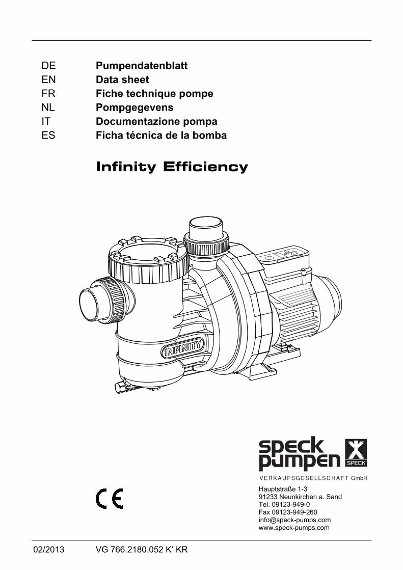
D76.40.003
422412
306
105
323
5
17013010
274
230
d D Rp 2
d S
Rp
2
120
244
609
44
225
44
SaD
a
~
~
8
2
00 5 15 25
Q (m³/h)
KL76.40.002
20
18
16
14
12
10
10
6
4
20
H (m
)
30 40
n=2400 min-1
50Hz / 60Hz
n=2000 min-1
n=1000 min-1
n=2830 min-1
02/2013 VG 766.2180.052 3
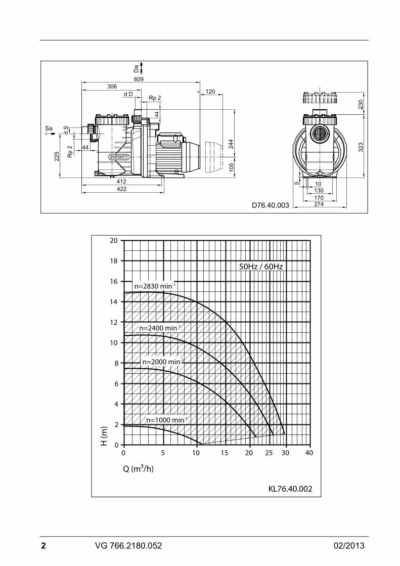
TD 50/60Hz Infinity Efficiency min.
1000 min-1 max.
2830 min-1 Sa Da d-Saug/mm d-Druck/mm L/mm
63 / Rp 2 63 / Rp 2
63 63
609 1~ 230 V P1/kW P2/kW I/A Lpa (1 m)/dB(A) Lwa/dB(A)
0,08 0,03 0,60 49,3 57
1,05 0,75 6,50 65,8 74
m/kg 9,0 WSK PTC
● ○
● ○
Hmax./m Sp Hs/m Hz/m
2,00 ● 3 3
15,0 ● 3 3
IP W-Kl n/min-1 T/°C P-GHI/bar max.
55 B
1000 40(60)
2,5
55 B
2830 40(60)
2,5
Glossar | Glossary | Glossaire | Woordenlijst | Glossario | Glosario TD
Technische Daten | Technical data | Données techniques | Technische gegevens | Dati tecnici | Datos técnicos
Sa Sauganschluss | Inlet connection | Raccordement aspiration | Zuigaansluiting | Raccordo aspirazione | Conexión por aspración
Da Druckanschluss | Outlet connection | Raccordement refoulement | Persaansluiting | Raccordo mandata | Conexión por presión

4 VG 766.2180.052 02/2013
Glossar | Glossary | Glossaire | Woordenlijst | Glossario | Glosario d-Saug Empfohlener Durchmesser der Saugleitung | Recommended
diameter - inlet connection | Diamètre recommandé conduite d’aspiration | Aanbevolen diameter van de zuigleiding | Diametro aspirazione consigliato | Diámetro recomendado de la conexión por aspiración
d-Druck Empfohlener Durchmesser der Druckleitung | Recommended diameter - outlet connection | Diamètre recommandé conduite de refoulement | Aanbevolen diameter van de persleiding | Diametro mandata consigliato | Diámetro recomendado de la conexión por presión
L Länge der Pumpe | Length of the pump | Longueur de la pompe | Lengte van de pomp | Lunghezza pompa | Largo de la bomba
P1 Aufgenommene Leistung | Power input | Puissance électrique | Opgenomen vermogen | Potenza assorbita | Potencia absorbida
P2 Abgegebene Leistung | Power output | Puissance restituée | Afgegeven vermogen | Potenza resa | Potencia disipada
I Nennstrom | Rated current | Intensité nominale | Nominale stroom | Corrente nominale | Corriente nominal
Lpa (1 m) Schalldruckpegel in 1 m Entfernung gemessen nach DIN 45635 | Sound pressure level at 1 m measured in accordance with DIN 45635 | Niveau de pression acoustique à un mètre de distance. Mesures effectuées conformément à DIN 45635. | Geluidsniveau gemeten bij 1 m. afstand volgens DIN 45635. | Livello di pressione acustica in 1 m di distanza. Misurato a norma DIN 45635. | Nivel de presión acústica a un metro de distancia. Mido según norma DIN 45635.
Lwa Schallleistung | Acoustic capacity | Intensité sonore | Geluidsniveau | Potenza acustica | Potencia acústica
m Gewicht | Weight | Poids | Gewicht | Peso | Peso WSK Wicklungsschutzkontakt oder Motorschutzschalter | Built-in or
external overlaod switch | Disjoncteur thermique intégré dans le bobinage ou disjoncteur protecteur du moteur | Wikkelingsbeschermingscontact of motorbeveiligingsschakelaar | Contatto di terra dell’avvolgimento oppure salvamotore | Protector térmico integrado en la bobina del motor
02/2013 VG 766.2180.052 5
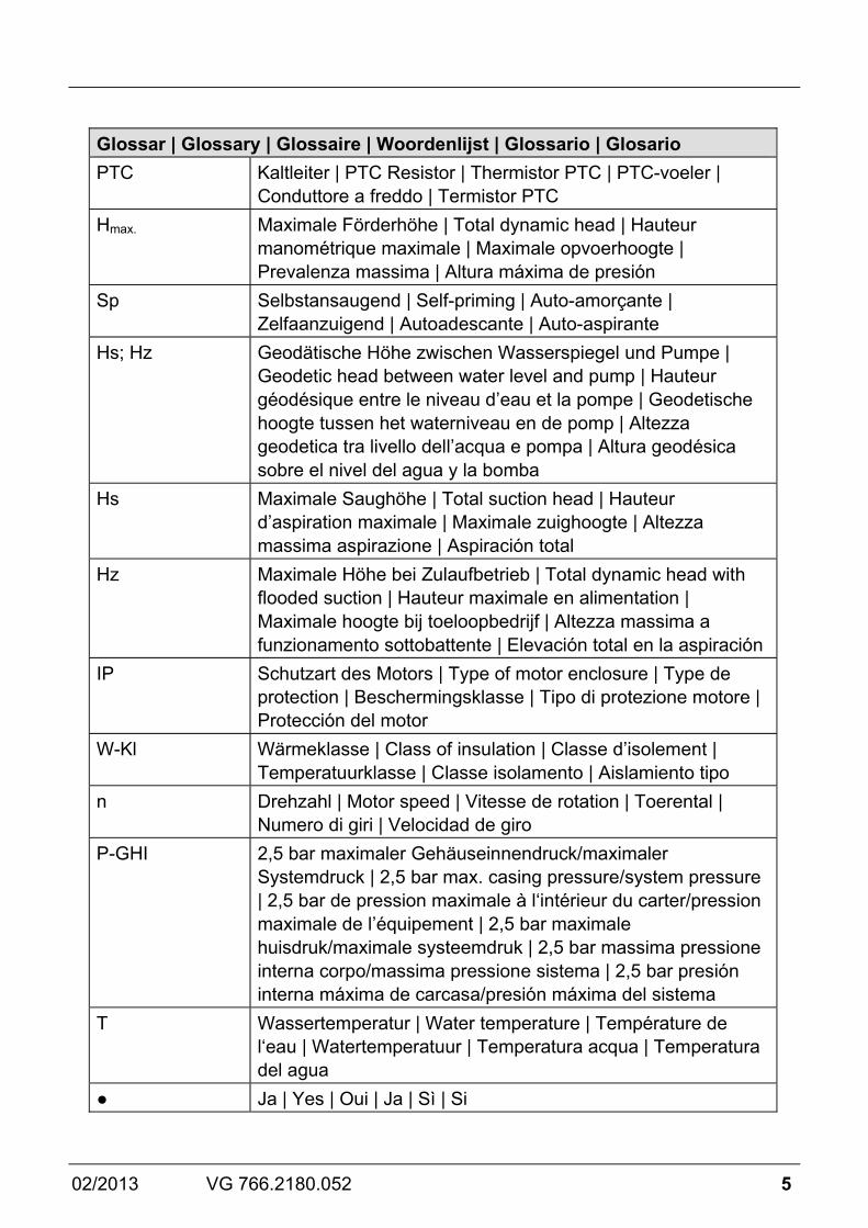
Glossar | Glossary | Glossaire | Woordenlijst | Glossario | Glosario PTC Kaltleiter | PTC Resistor | Thermistor PTC | PTC-voeler |
Conduttore a freddo | Termistor PTC Hmax. Maximale Förderhöhe | Total dynamic head | Hauteur
manométrique maximale | Maximale opvoerhoogte | Prevalenza massima | Altura máxima de presión
Sp Selbstansaugend | Self-priming | Auto-amorçante | Zelfaanzuigend | Autoadescante | Auto-aspirante
Hs; Hz Geodätische Höhe zwischen Wasserspiegel und Pumpe | Geodetic head between water level and pump | Hauteur géodésique entre le niveau d’eau et la pompe | Geodetische hoogte tussen het waterniveau en de pomp | Altezza geodetica tra livello dell’acqua e pompa | Altura geodésica sobre el nivel del agua y la bomba
Hs Maximale Saughöhe | Total suction head | Hauteur d’aspiration maximale | Maximale zuighoogte | Altezza massima aspirazione | Aspiración total
Hz Maximale Höhe bei Zulaufbetrieb | Total dynamic head with flooded suction | Hauteur maximale en alimentation | Maximale hoogte bij toeloopbedrijf | Altezza massima a funzionamento sottobattente | Elevación total en la aspiración
IP Schutzart des Motors | Type of motor enclosure | Type de protection | Beschermingsklasse | Tipo di protezione motore | Protección del motor
W-Kl Wärmeklasse | Class of insulation | Classe d’isolement | Temperatuurklasse | Classe isolamento | Aislamiento tipo
n Drehzahl | Motor speed | Vitesse de rotation | Toerental | Numero di giri | Velocidad de giro
P-GHI 2,5 bar maximaler Gehäuseinnendruck/maximaler Systemdruck | 2,5 bar max. casing pressure/system pressure | 2,5 bar de pression maximale à l‘intérieur du carter/pression maximale de l’équipement | 2,5 bar maximale huisdruk/maximale systeemdruk | 2,5 bar massima pressione interna corpo/massima pressione sistema | 2,5 bar presión interna máxima de carcasa/presión máxima del sistema
T Wassertemperatur | Water temperature | Température de l‘eau | Watertemperatuur | Temperatura acqua | Temperatura del agua
● Ja | Yes | Oui | Ja | Sì | Si

6 VG 766.2180.052 02/2013
Glossar | Glossary | Glossaire | Woordenlijst | Glossario | Glosario ○ Nein | No | Non | Nee | No | No T/°C Erläuterung Wassertemperatur 40°C (60°C): 40°C = gilt für
maximale Wassertemperatur im Sinne des GS-Zeichens. (60°C) = Pumpe ist ohne Weiteres für eine max. Wassertemperatur von 60 C einsetzbar/ausgelegt. | Clarification of the max. water temperature 40°C (60°C): 40°C = the max. water temperature allowed according to the GS approval. (60°C) = the pump is designed to withstand a max. water temperature of 60°C. | Informations sur la température de l’eau 40°C (60°C): 40°C = valable pour une température maximale en conformité avec le sigle GS. (60°C) = Cependant, la pompe est facilement utilisable/étalonnée pour une température maximale de l’eau de 60°C. | Verklaring watertemperatuur 40°C (60°C): 40°C = max. watertemperatuur in combinatie met het GS-keurmerk. 60°C = de pomp is geschikt voor een max. watertemperatuur van 60°C. | Spiegazione temperatura acqua 40°C (60°C): 40°C = temperatura massima dell’acqua ai sensi del marchio GS. (60°C) = la pompa può senz’altro funzionare anche con una temperatura acqua massima di 60°C. | Explicación de la temperatura del aqua 40°C (60°C): 40°C = vale para temperaturas máximas conforme a las normas GS. (60°C) = La bomba puede funcionar para una temperatura del agua de 60°C.
1~/3~ Geeignet für Dauerbetrieb bei | Suitable for continuous operation at | Adaptée à un fonctionnement ininterrompu à | Geschikt voor continu gebruik bij | Adatta per funzionamento continuo a | Apropiado para un servicio continuo a 1~ 220 - 240 V ± 5% 3~ Y/∆ 380 - 420 V/220 - 240 V ± 5% 3~ Y/∆ 660 - 725 V/380 - 420 V ± 5%
Für Normspannung geeignet nach | For standard voltage in accordance with | Appropriée à une tension conforme aux normes | Voor normspanning volgens | Adatta per tensione standard secondo normative | Apropiado para una tensión según la normas DIN IEC 60038; DIN EN 60034.
DE
02/2013 VG 766.2180.052 7
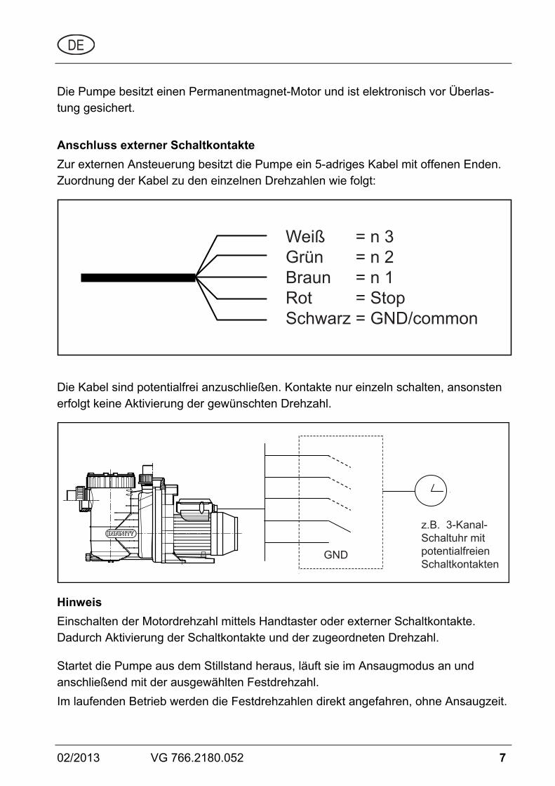
Die Pumpe besitzt einen Permanentmagnet-Motor und ist elektronisch vor Überlas-tung gesichert.
Anschluss externer Schaltkontakte Zur externen Ansteuerung besitzt die Pumpe ein 5-adriges Kabel mit offenen Enden. Zuordnung der Kabel zu den einzelnen Drehzahlen wie folgt:
Weiß = n 3Grün = n 2Braun = n 1Rot = Stop Schwarz = GND/common
Die Kabel sind potentialfrei anzuschließen. Kontakte nur einzeln schalten, ansonsten erfolgt keine Aktivierung der gewünschten Drehzahl.
GND
z.B. 3-Kanal-Schaltuhr mitpotentialfreienSchaltkontakten
Hinweis Einschalten der Motordrehzahl mittels Handtaster oder externer Schaltkontakte. Dadurch Aktivierung der Schaltkontakte und der zugeordneten Drehzahl.
Startet die Pumpe aus dem Stillstand heraus, läuft sie im Ansaugmodus an und anschließend mit der ausgewählten Festdrehzahl. Im laufenden Betrieb werden die Festdrehzahlen direkt angefahren, ohne Ansaugzeit.

8 VG 766.2180.052 02/2013
Wird die externe Ansteuerung nicht benötigt, müssen die Kabelenden isoliert werden.
Hinweis Der Einbau eines Strömungswächters in die Umwälzleitung wird empfohlen, damit eine Störmeldung angezeigt werden kann. Hierdurch kann eine längere Unter-brechung des Badewasserkreislaufes vermieden werden.
02/2013 VG 766.2180.052 9
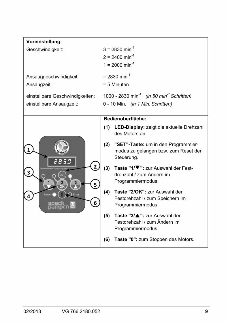
Voreinstellung: Geschwindigkeit: 3 = 2830 min-1 2 = 2400 min-1 1 = 2000 min-1
Ansauggeschwindigkeit: = 2830 min-1 Ansaugzeit: = 5 Minuten
einstellbare Geschwindigkeiten: 1000 - 2830 min-1 (in 50 min-1 Schritten) einstellbare Ansaugzeit: 0 - 10 Min. (in 1 Min. Schritten)
Bedienoberfläche: (1) LED-Display: zeigt die aktuelle Drehzahl
des Motors an.
(2) "SET"-Taste: um in den Programmier-modus zu gelangen bzw. zum Reset der Steuerung.
(3) Taste "1/ ": zur Auswahl der Fest-drehzahl / zum Ändern im Programmiermodus.
(4) Taste "2/OK": zur Auswahl der Festdrehzahl / zum Speichern im Programmiermodus.
(5) Taste "3/ ": zur Auswahl der Festdrehzahl / zum Ändern im Programmiermodus.
(6) Taste "0": zum Stoppen des Motors.
1
2
5
6
3
4

10 VG 766.2180.052 02/2013
Bedienung: Taste "1", "2" oder "3" drücken, um die voreingestellte Festdrehzahl auszuwählen. Startet die Pumpe aus dem Stillstand heraus, läuft sie im Ansaugmodus an und anschlie-ßend mit der ausgewählten Festdrehzahl. Solange sich die Pumpe in der Ansaugphase befindet, blinkt die LED der ausgewählten Drehzahl. Im laufenden Betrieb werden die Festdreh-zahlen direkt angefahren, ohne Ansaugzeit. Durch drücken der Taste "0" wird der Motor gestoppt. Die "Power"-LED blinkt und das Display zeigt "OFF" an.
Hinweis: Bei der Verwendung der Infinity Efficiency mit einer externen Steuerung, muss beim programmieren der Drehzahlen und der Ansaug- zeit die Verbindung zu der externen Steuerung unterbrochen oder diese von der Netzspannung getrennt werden!
Einstellen der Festdrehzahlen Die Taste der Festdrehzahl, die verändert werden soll, drücken und danach die "SET"-Taste für min. 3 Sekunden halten, bis die Drehzahlanzeige im Display anfängt zu blinken. Nun kann die Drehzahl mit den Tasten “▼▲” geändert werden. Zum Speichern der Drehzahl mit "OK" bestätigen. Zum Abbrechen und beibehalten der Ursprungsdrehzahl die "SET"-Taste drücken.

02/2013 VG 766.2180.052 11
Einstellen der Ansaugparameter Zum Programmieren der Ansaugzeit muss der Motor gestoppt werden (Taste "0"). Dann wieder die "SET"-Taste für min. 3 Sekunden drücken, bis die Drehzahlanzeige im Display anfängt zu blinken. Nun kann die Drehzahl eingestellt werden, mit der der Motor während der Ansaugzeit fahren soll. Mit den Tasten “▼▲” kann die Drehzahl geändert und mit "OK" gespeichert werden. Nachdem die Ansaugdrehzahl eingestellt wurde, kann die Länge der Ansaugzeit bestimmt werden. Diese kann von 0 (= Aus) bis 10 Minuten eingestellt werden. Zurücksetzen / Reset Durch drücken der "SET"-Taste für min. 15 Sekunden, kann der Motor wieder zurück in den Auslieferungszustand versetzt werden. Der Motor stoppt und die drei LED's der Festdrehzahlen leuchten auf.

12 VG 766.2180.052 02/2013
Das Display der Steuerung schaltet sich nach drei Minuten ohne Aktion ab, außer eine externe Steuerung gibt z.B. jede Minute ein Signal an die Pumpe.
Die Pumpe läuft nach einem Spannungsverlust automatisch wieder mit der zuletzt eingestellten Drehzahl an oder bleibt stehen wenn sie zuvor gestoppt wurde.

02/2013 VG 766.2180.052 13
Übersicht möglicher Betriebs- und Fehlermeldungen Ist ein Fehler aufgetreten, schaltet der Motor dauerhaft ab. Ausnahmefehler: „Unterspannung“. Hier schaltet der Motor wieder selbsttätig ein, sofern die Spannung für mindestens 6 sec. über 209 V liegt.
Tritt ein Fehler auf, so ist die Anlage von der Spannungsversorgung zu trennen. Siehe Kapitel 2.2 der Originalbetriebsanleitung „Normal und selbstansaugende Pumpen mit/ohne Kunststofflaternen-Ausführung (AK)“.
Störung Blinkrate rote LED-Error Mögliche Ursache Abhilfe
1 Störung Mikroprozessor Mikroprozessor startet neu 2 Unterspannung Spannungsversorgung
< 180 V AC Steuerung aktiviert sich selbstständig wenn Spannung für mehr als 6 sec. über 209 V ist
3 Temperatur zu hoch / Zu niedrig
Temperatur zu hoch > 100°C
Temperatur zu niedrig < -20°C
4 Überstromauslösung Strom zu hoch Interner Überstromschutz geschaltet
5 Überspannung Spannungsversorgung > 269 VAC
6 Welle blockiert Last an der Welle zu hoch oder
Motor angehalten 7 Eigentest Ein oder mehrere
Eigentests nicht erfolgreich ausgeführt
8 Motorfehler Eine oder mehrere Phasen sind nicht angeschlossen

14 VG 766.2180.052 02/2013
Mitgeltende Dokumente Zu diesem Pumpendatenblatt gehört die Originalbetriebsanleitung "Normal und selbstansaugende Pumpen mit/ohne Kunststofflaternen-Ausführung (AK)". Sie muss für das Bedien- und Wartungspersonal frei zugänglich sein.
EN
02/2013 VG 766.2180.052 15
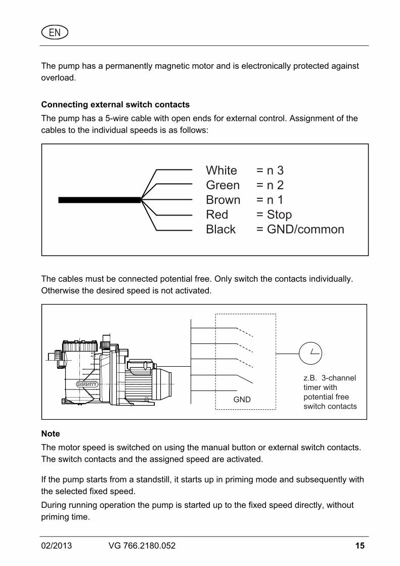
The pump has a permanently magnetic motor and is electronically protected against overload.
Connecting external switch contacts The pump has a 5-wire cable with open ends for external control. Assignment of the cables to the individual speeds is as follows:
White = n 3Green = n 2Brown = n 1Red = Stop Black = GND/common
The cables must be connected potential free. Only switch the contacts individually. Otherwise the desired speed is not activated.
GND
z.B. 3-channeltimer withpotential freeswitch contacts
Note The motor speed is switched on using the manual button or external switch contacts. The switch contacts and the assigned speed are activated.
If the pump starts from a standstill, it starts up in priming mode and subsequently with the selected fixed speed. During running operation the pump is started up to the fixed speed directly, without priming time.
16 VG 766.2180.052 02/2013
If external control is not necessary, the cable ends need to be insulated.
Note Installing a flow monitor in the circulation line is recommended so that a failure message can be displayed. A lengthy interruption of the bath water circulation can be prevented in this way.
02/2013 VG 766.2180.052 17
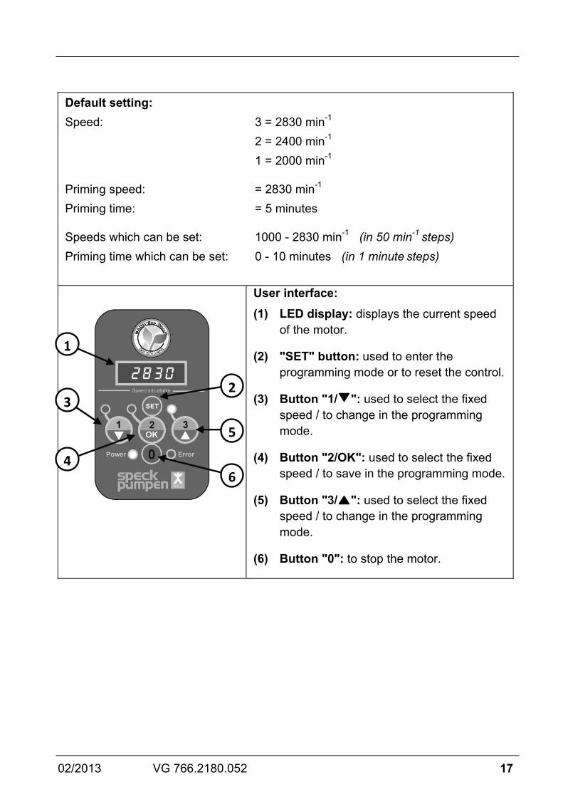
Default setting: Speed: 3 = 2830 min-1 2 = 2400 min-1 1 = 2000 min-1
Priming speed: = 2830 min-1 Priming time: = 5 minutes
Speeds which can be set: 1000 - 2830 min-1 (in 50 min-1 steps) Priming time which can be set: 0 - 10 minutes (in 1 minute steps)
User interface: (1) LED display: displays the current speed
of the motor.
(2) "SET" button: used to enter the programming mode or to reset the control.
(3) Button "1/ ": used to select the fixed speed / to change in the programming mode.
(4) Button "2/OK": used to select the fixed speed / to save in the programming mode.
(5) Button "3/ ": used to select the fixed speed / to change in the programming mode.
(6) Button "0": to stop the motor.
1
2
5
6
3
4
18 VG 766.2180.052 02/2013
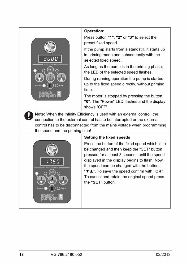
Operation: Press button "1", "2" or "3" to select the preset fixed speed. If the pump starts from a standstill, it starts up in priming mode and subsequently with the selected fixed speed. As long as the pump is in the priming phase, the LED of the selected speed flashes. During running operation the pump is started up to the fixed speed directly, without priming time. The motor is stopped by pressing the button "0". The "Power" LED flashes and the display shows "OFF".
Note: When the Infinity Efficiency is used with an external control, the connection to the external control has to be interrupted or the external control has to be disconnected from the mains voltage when programming the speed and the priming time!
Setting the fixed speeds Press the button of the fixed speed which is to be changed and then keep the "SET" button pressed for at least 3 seconds until the speed displayed in the display begins to flash. Now the speed can be changed with the buttons “▼▲”. To save the speed confirm with "OK". To cancel and retain the original speed press the "SET" button.

02/2013 VG 766.2180.052 19
Setting the priming parameters The motor has to be stopped ("0" button) to programme the priming time. Then press the "SET" button again for at least 3 seconds until the speed displayed in the display begins to flash. Now the speed can be set with which the motor is to start up during the priming time. The speed can be changed with the buttons “▼▲” and saved with "OK". After the priming speed has been set, the length of the priming time can be specified. The priming time can be set between 0 (= Off) and 10 minutes.
Resetting The motor can be reset to the state of delivery by pressing the "SET" button for at least 15 seconds. The motor stops and the three LEDs of the fixed speeds light up.

20 VG 766.2180.052 02/2013
The display of the control unit switches off after 3 minutes without action, except if an external control unit for example emits a signal to the pump every minute.
After a voltage drop the pump automatically starts up again with the speed last set, or remains stopped if it had been stopped beforehand.

02/2013 VG 766.2180.052 21
Overview of possible operating and error messages If an error occurs, the motor switches off permanently. Exception error: "Undervoltage". The motor automatically switches back on as soon as the voltage lies over 209 V for at least 6 seconds.
If an error occurs, the system must be disconnected from the power supply. See Chapter 2.2 of the original Operating Manual "Non self-priming and self-priming pumps with/without plastic lanterns (AK version)".
Failure blink rate red error LED Possible cause Solution
1 Failure of the microprocessor
Microprocessor restarts
2 Undervoltage Power supply < 180 V AC
Controller automatically activates when the voltage is over 209 V for at least 6 seconds
3 Temperature too high / too low
Temperature too high > 100°C
Temperature too low < -20°C
4 Overcurrent triggering Current too high Internal overcurrent protection switched
5 Overvoltage Power supply > 269 V AC
6 Shaft blocked Load on the shaft too high or
motor stopped 7 Self-test One or more self-tests not
run successfully 8 Motor error One or more phases not
connected
22 VG 766.2180.052 02/2013
Related Documentation The additional information compiled in this data sheet must be kept together with the original Operating Manual for "Non self-priming and self-priming pumps with/without plastic lanterns (AK version)" and must be accessible to the relevant personnel at all times.
FR
02/2013 VG 766.2180.052 23
La pompe possède un moteur à entraînement électro magnétique avec protection contre la surcharge.
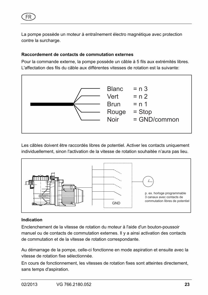
Raccordement de contacts de commutation externes Pour la commande externe, la pompe possède un câble à 5 fils aux extrémités libres. L'affectation des fils du câble aux différentes vitesses de rotation est la suivante:
Blanc = n 3Vert = n 2Brun = n 1Rouge = Stop Noir = GND/common
Les câbles doivent être raccordés libres de potentiel. Activer les contacts uniquement individuellement, sinon l'activation de la vitesse de rotation souhaitée n’aura pas lieu.
GND
p. ex. horloge programmable 3 canaux avec contacts decommutation libres de potentiel
Indication Enclenchement de la vitesse de rotation du moteur à l'aide d'un bouton-poussoir manuel ou de contacts de commutation externes. Il y a ainsi activation des contacts de commutation et de la vitesse de rotation correspondante.
Au démarrage de la pompe, celle-ci fonctionne en mode aspiration et ensuite avec la vitesse de rotation fixe sélectionnée. En cours de fonctionnement, les vitesses de rotation fixes sont atteintes directement, sans temps d'aspiration.

24 VG 766.2180.052 02/2013
Lorsque la commande externe n'est pas nécessaire, les extrémités des câbles doivent être isolées.
Indication Le montage d'un contrôleur de débit dans la tuyauterie est recommandé afin de permettre l’affichage d’un message d’erreur. Ceci afin d'éviter une trop longue interruption de la circulation de l'eau de la piscine.

02/2013 VG 766.2180.052 25
Préréglage: Vitesse: 3 = 2830 min-1 2 = 2400 min-1 1 = 2000 min-1
Vitesse d'aspiration: = 2830 min-1 Temps d'aspiration: = 5 minutes
Vitesses réglables: 1000 - 2830 min-1 (par intervalles de 50 min-1) Temps d'aspiration réglable: 0 - 10 min (pas intervalles d’une min.)
Interface de commande: (1) Affichage LED: indique la vitesse de
rotation actuelle du moteur.
(2) Touche "SET": sert à parvenir dans le mode de programmation ou à réinitialiser la commande.
(3) Touche "1/ ": sert à la sélection de la vitesse de rotation fixe / à ka modification dans le mode de programmation.
(4) Touche "2/OK": sert à la sélection de la vitesse de rotation fixe / à l’enregistrement dans le mode de programmation.
(5) Touche "3/ ": sert à la sélection de la vitesse de rotation fixe / à la modification dans le mode de programmation.
(6) Touche "0": arrêt du moteur.
1
2
5
6
3
4

26 VG 766.2180.052 02/2013
Mise en service: Appuyer sur la touche "1", "2" ou "3" pour sélectionner la vitesse de rotation fixe prédéfinie. Au démarrage de la pompe, celle-ci tourne en mode aspiration et ensuite avec la vitesse de rotation fixe sélectionnée. Aussi longtemps que la pompe est en phase d'aspiration, la LED de la vitesse de rotation sélectionnée clignote. En cours de fonctionnement, les vitesses de rotation fixes sont atteintes directement, sans temps d'aspiration. En appuyant sur la touche "0", le moteur est coupé. La LED "Power" clignote et l'écran affiche "OFF".
Indication: En cas d'utilisation de la Infinity Efficiency avec une commande externe, pendant la programmation des vitesses de rotation et du temps d'aspiration, la liaison à la commande externe doit être interrompue ou séparée de la tension de réseau!
Réglage des vitesses de rotation fixes Appuyer sur la touche de la vitesse de rotation fixe qui doit être modifiée et ensuite sur la touche "SET" pendant au moins 3 secondes, jusqu'à ce que l'affichage de vitesse de rotation à l’écran commence à clignoter. On peut maintenant modifier la vitesse de rotation avec les touches “▼▲”. Pour enregistrer la vitesse de rotation, confirmer avec "OK". Pour interrompre et conserver la vitesse de rotation antérieure, appuyer sur la touche "SET".

02/2013 VG 766.2180.052 27
Réglage des paramètres d'aspiration Pour la programmation du temps d'aspiration, le moteur doit être coupé (touche "0"). Ensuite, appuyer à nouveau pendant au moins 3 seconds sur la touche "SET", jusqu'à ce que l'affichage de vitesse de rotation à l’écran commence à clignoter. On peut maintenant régler la vitesse de rotation du moteur pendant le temps d'aspiration. Avec les touches “▼▲”, on peut modifier la vitesse du moteur et l'enregistrer avec "OK". Après avoir réglé la vitesse de rotation d'aspiration, on peut déterminer la durée du temps d'aspiration. Celle-ci peut être réglée de 0 (= arrêt) à 10 minutes.
Réinitialiser / Reset En appuyant sur la touche "SET" pendant au moins 15 secondes, on peut remettre le moteur dans l'état d’origine. Le moteur se coupe et les trois LED des vitesses de rotation fixes s'allument.

28 VG 766.2180.052 02/2013
L'écran de la commande s'éteint après trois minutes sans activité, sauf si une commande externe donne p. ex. à chaque minute un signal à la pompe.
Après une coupure de tension, la pompe tourne automatiquement à nouveau avec la vitesse de rotation réglée en dernier lieu ou demeure à l’arrêt si elle avait été préalablement coupée.
02/2013 VG 766.2180.052 29
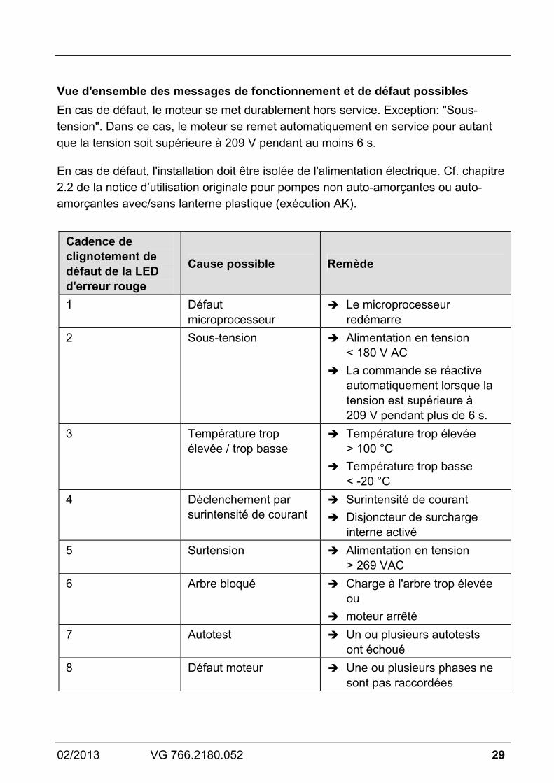
Vue d'ensemble des messages de fonctionnement et de défaut possibles En cas de défaut, le moteur se met durablement hors service. Exception: "Sous-tension". Dans ce cas, le moteur se remet automatiquement en service pour autant que la tension soit supérieure à 209 V pendant au moins 6 s.
En cas de défaut, l'installation doit être isolée de l'alimentation électrique. Cf. chapitre 2.2 de la notice d’utilisation originale pour pompes non auto-amorçantes ou auto-amorçantes avec/sans lanterne plastique (exécution AK).
Cadence de clignotement de défaut de la LED d'erreur rouge
Cause possible Remède
1 Défaut microprocesseur
Le microprocesseur redémarre
2 Sous-tension Alimentation en tension < 180 V AC
La commande se réactive automatiquement lorsque la tension est supérieure à 209 V pendant plus de 6 s.
3 Température trop élevée / trop basse
Température trop élevée > 100 °C
Température trop basse < -20 °C
4 Déclenchement par surintensité de courant
Surintensité de courant Disjoncteur de surcharge
interne activé 5 Surtension Alimentation en tension
> 269 VAC 6 Arbre bloqué Charge à l'arbre trop élevée
ou moteur arrêté
7 Autotest Un ou plusieurs autotests ont échoué
8 Défaut moteur Une ou plusieurs phases ne sont pas raccordées
30 VG 766.2180.052 02/2013
Documents applicables Le présent document fait partie intégrante de la notice d’utilisation originale pour pompes non auto-amorçantes ou auto-amorçantes avec/sans lanterne plastique (exécution AK). Il est recommandé de le tenir accessible aux personnes chargées de l’utilisation et de la maintenance.

NL
02/2013 VG 766.2180.052 31
De pomp is voorzien van een motor met permanente magneet en is elektronisch beveiligd tegen overbelasting.
Aansluiting van externe schakelcontacten Voor externe aansturing is de pomp voorzien van een 5-aderige kabel met open uiteinden. De aders van de kabel zijn als volgt toegewezen aan de betreffende toerentallen:
Wit = n 3Groen = n 2Bruin = n 1Rood = Stop Zwart = GND/common
De kabels moeten potentiaalvrij worden aangesloten. Schakel slechts één contact tegelijk in, anders wordt het gewenste toerental niet geactiveerd.
GND
b.v. 3-kanaalsschakelklok metpotentiaalvrijeschakelcontacten
Aanwijzing Inschakelen van de motor met de handschakelaar of met externe schakelcontacten. Daardoor wordt het betreffende schakelcontact en het toegewezen toerental geactiveerd.
Wanneer de pomp start vanuit stilstand, loopt deze aan in de aanzuigstand en aansluitend met het geselecteerde vaste toerental.

32 VG 766.2180.052 02/2013
Wanneer de pomp al in bedrijf is, gaat deze direct naar de vaste toerentallen, zonder aanzuigtijd.
Wanneer externe aansturing niet nodig is, moeten de uiteinden van de kabel worden geïsoleerd.
Aanwijzing Het wordt aanbevolen in de circulatieleiding een stromingssensor te installeren waarmee een storingsmelding kan worden gegenereerd. Hierdoor kunnen lange onderbrekingen van de zwembadwatercirculatie worden voorkomen.

02/2013 VG 766.2180.052 33
Standaardinstelling: Snelheid: 3 = 2830 min-1 2 = 2400 min-1 1 = 2000 min-1
Aanzuigsnelheid: = 2830 min-1 Aanzuigtijd: = 5 minuten
Instelbare snelheden: 1000 - 2830 min-1 (in stappen van 50 min-1 ) Instelbare aanzuigtijd: 0 - 10 min. (in stappen van 1 min.)
Bedieningsinterface: (1) LED-display: geeft het huidige toerental
van de motor aan.
(2) "SET"-toets: om in de programmeerstand te komen resp. om de besturing te resetten.
(3) Toets "1/ ": om het vaste toerental te selecteren / voor wijzigen in de programmeerstand.
(4) Toets "2/OK": om het vaste toerental te selecteren / voor opslaan in de programmeerstand.
(5) Toets "3/ ": om het vaste toerental te selecteren / voor wijzigen in de programmeerstand.
(6) Toets "0": om de motor te stoppen.
1
2
5
6
3
4
34 VG 766.2180.052 02/2013
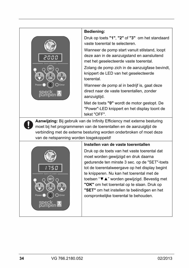
Bediening: Druk op toets "1", "2" of "3" om het standaard vaste toerental te selecteren. Wanneer de pomp start vanuit stilstand, loopt deze aan in de aanzuigstand en aansluitend met het geselecteerde vaste toerental. Zolang de pomp zich in de aanzuigfase bevindt, knippert de LED van het geselecteerde toerental. Wanneer de pomp al in bedrijf is, gaat deze direct naar de vaste toerentallen, zonder aanzuigtijd. Met de toets "0" wordt de motor gestopt. De "Power"-LED knippert en het display toont de tekst "OFF".
Aanwijzing: Bij gebruik van de Infinity Efficiency met externe besturing moet bij het programmeren van de toerentallen en de aanzuigtijd de verbinding met de externe besturing worden onderbroken of moet deze van de netspanning worden losgekoppeld!
Instellen van de vaste toerentallen Druk op de toets van het vaste toerental dat moet worden gewijzigd en druk daarna gedurende ten minste 3 sec. op de "SET"-toets tot de toerentalweergave op het display begint te knipperen. Nu kan het toerental met de toetsen “▼▲” worden gewijzigd. Bevestig met "OK" om het toerental op te slaan. Druk op "SET" om het instellen te beëindigen en het oorspronkelijke toerental te behouden.
02/2013 VG 766.2180.052 35
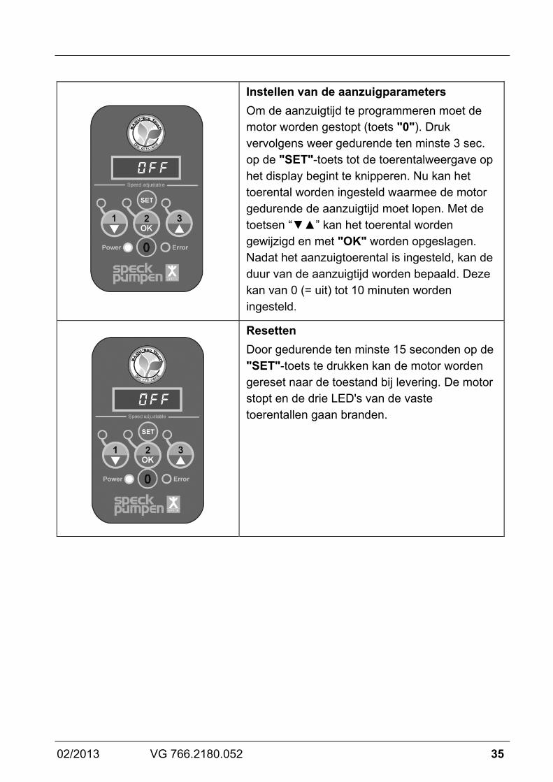
Instellen van de aanzuigparameters Om de aanzuigtijd te programmeren moet de motor worden gestopt (toets "0"). Druk vervolgens weer gedurende ten minste 3 sec. op de "SET"-toets tot de toerentalweergave op het display begint te knipperen. Nu kan het toerental worden ingesteld waarmee de motor gedurende de aanzuigtijd moet lopen. Met de toetsen “▼▲” kan het toerental worden gewijzigd en met "OK" worden opgeslagen. Nadat het aanzuigtoerental is ingesteld, kan de duur van de aanzuigtijd worden bepaald. Deze kan van 0 (= uit) tot 10 minuten worden ingesteld.
Resetten Door gedurende ten minste 15 seconden op de "SET"-toets te drukken kan de motor worden gereset naar de toestand bij levering. De motor stopt en de drie LED's van de vaste toerentallen gaan branden.
36 VG 766.2180.052 02/2013
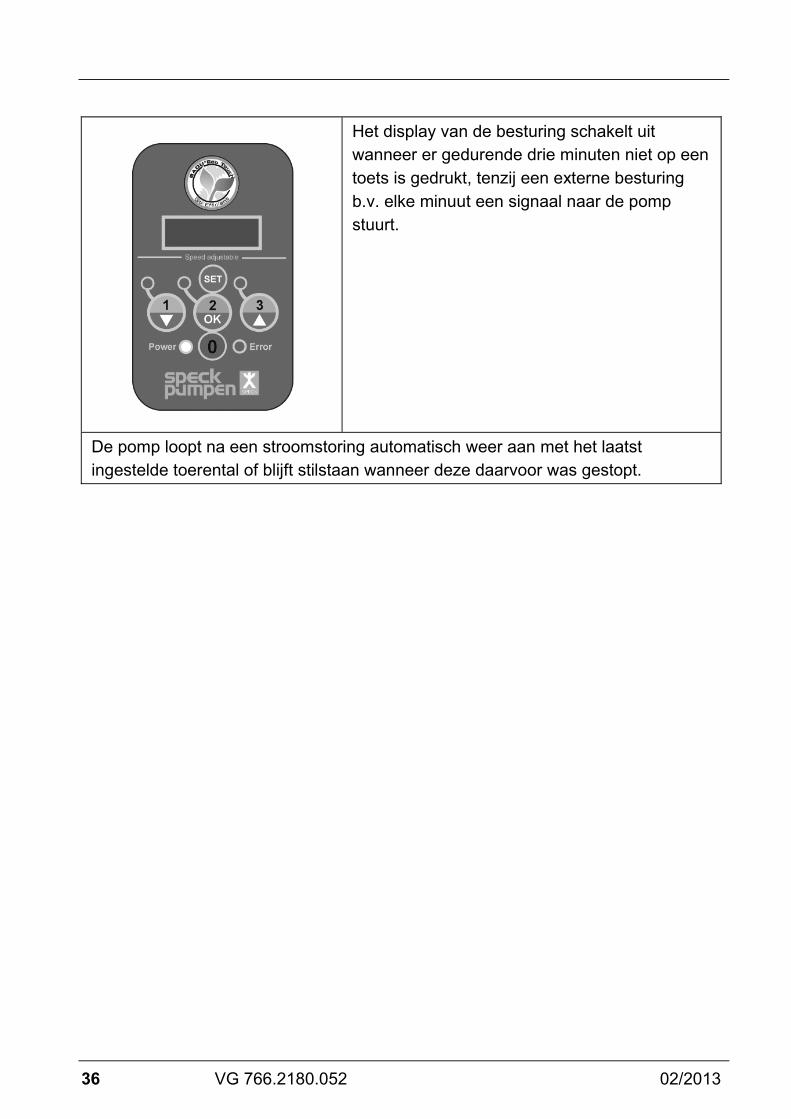
Het display van de besturing schakelt uit wanneer er gedurende drie minuten niet op een toets is gedrukt, tenzij een externe besturing b.v. elke minuut een signaal naar de pomp stuurt.
De pomp loopt na een stroomstoring automatisch weer aan met het laatst ingestelde toerental of blijft stilstaan wanneer deze daarvoor was gestopt.
02/2013 VG 766.2180.052 37
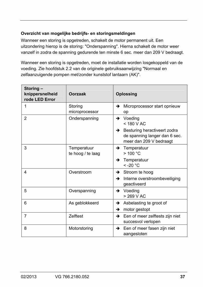
Overzicht van mogelijke bedrijfs- en storingsmeldingen Wanneer een storing is opgetreden, schakelt de motor permanent uit. Een uitzondering hierop is de storing: "Onderspanning". Hierna schakelt de motor weer vanzelf in zodra de spanning gedurende ten minste 6 sec. meer dan 209 V bedraagt.
Wanneer een storing is opgetreden, moet de installatie worden losgekoppeld van de voeding. Zie hoofdstuk 2.2 van de originele gebruiksaanwijzing "Normaal en zelfaanzuigende pompen met/zonder kunststof lantaarn (AK)".
Storing – knippersnelheid rode LED Error
Oorzaak Oplossing
1 Storing microprocessor
Microprocessor start opnieuw op
2 Onderspanning Voeding < 180 V AC
Besturing heractiveert zodra de spanning langer dan 6 sec. meer dan 209 V bedraagt
3 Temperatuur te hoog / te laag
Temperatuur > 100 °C
Temperatuur < -20 °C
4 Overstroom Stroom te hoog Interne overstroombeveiliging
geactiveerd 5 Overspanning Voeding
> 269 V AC 6 As geblokkeerd Asbelasting te groot of
motor gestopt 7 Zelftest Een of meer zelftests zijn niet
succesvol verlopen 8 Motorstoring Een of meer fasen zijn niet
aangesloten

38 VG 766.2180.052 02/2013
Relevante documenten Bij dit pompdatablad hoort de originele gebruiksaanwijzing "Normaal en zelfaanzuigende pompen met/zonder kunststof lantaarn (AK)". Deze moet voor het bedienings- en onderhoudspersoneel te allen tijde beschikbaar zijn.

IT
02/2013 VG 766.2180.052 39
La pompa possiede un motore a magneti permanenti ed è protetta elettronicamente dal sovraccarico.
Collegamento di contatti di commutazione esterni Per il comando esterno, la pompa possiede un cavo a 5 conduttori con estremità aperte. I conduttori del cavo sono associati ai seguenti numeri di giri:
Blanco = n 3Verde = n 2Marrone = n 1Rosso = Stop Nero = GND/common
Il cavo deve essere collegato a morsetti a potenziale zero. Commutare i contatti solo singolarmente, altrimenti il numero di giri desiderato non si attiva.
GND
ad esempio timer a3 canali con contattidi commutazione apotenziale zero
Avviso Attivazione del numero di giri del motore mediante pulsanti manuali o contatti di commutazione esterni. In tal modo si attivano i contatti di commutazione ed il numero di giri associato.
Avviando la pompa da ferma, essa inizia a funzionare in modalità di aspirazione e poi con il numero di giri fisso selezionato.

40 VG 766.2180.052 02/2013
A pompa in funzione, i numeri di giri fissi vengono raggiunti direttamente senza tempo di aspirazione. Se il comando esterno non è necessario, le estremità del cavo devono essere isolati.
Avviso È consigliabile montare un regolatore di portata nella tubazione di circolazione in modo che venga visualizzato un messaggio di guasto. In questo modo si può evitare un'interruzione relativamente lunga del circuito dell'acqua da bagno.

02/2013 VG 766.2180.052 41
Impostazione predefinita: Velocità: 3 = 2830 min-1 2 = 2400 min-1 1 = 2000 min-1
Velocità in modalità di aspirazione: = 2830 min-1 Tempo di aspirazione: = 5 minuti
Velocità regolabili: 1000 - 2830 min-1 (ad incrementi di 50 min-1) Tempo di aspirazione regolabile: 0 - 10 min (ad incrementi di 1 min)
Pannello di controllo: (1) Display a LED: visualizza il numero di giri
attuale del motore.
(2) Tasto "SET": per accedere alla modalità di programmazione o per resettare la centralina di comando.
(3) Tasto "1/ ": per selezionare il numero di giri fisso / per modificare nella modalità di programmazione.
(4) Tasto "2/OK": per selezionare il numero di giri fisso / per salvare nella modalità di programmazione.
(5) Tasto "3/ ": per selezionare il numero di giri fisso / per modificare nella modalità di programmazione.
(6) Tasto "0": per arrestare il motore.
1
2
5
6
3
4
42 VG 766.2180.052 02/2013
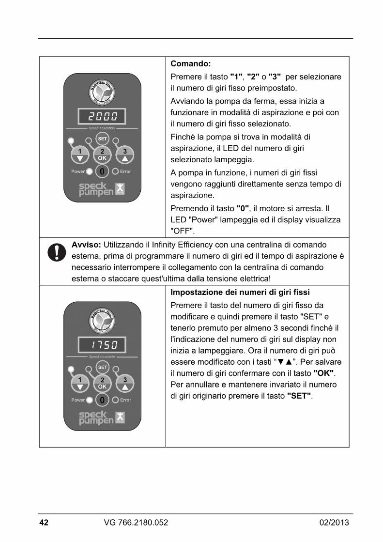
Comando: Premere il tasto "1", "2" o "3" per selezionare il numero di giri fisso preimpostato. Avviando la pompa da ferma, essa inizia a funzionare in modalità di aspirazione e poi con il numero di giri fisso selezionato. Finché la pompa si trova in modalità di aspirazione, il LED del numero di giri selezionato lampeggia. A pompa in funzione, i numeri di giri fissi vengono raggiunti direttamente senza tempo di aspirazione. Premendo il tasto "0", il motore si arresta. Il LED "Power" lampeggia ed il display visualizza "OFF".
Avviso: Utilizzando il Infinity Efficiency con una centralina di comando esterna, prima di programmare il numero di giri ed il tempo di aspirazione è necessario interrompere il collegamento con la centralina di comando esterna o staccare quest'ultima dalla tensione elettrica!
Impostazione dei numeri di giri fissi Premere il tasto del numero di giri fisso da modificare e quindi premere il tasto "SET" e tenerlo premuto per almeno 3 secondi finché il l'indicazione del numero di giri sul display non inizia a lampeggiare. Ora il numero di giri può essere modificato con i tasti “▼▲”. Per salvare il numero di giri confermare con il tasto "OK". Per annullare e mantenere invariato il numero di giri originario premere il tasto "SET".

02/2013 VG 766.2180.052 43
Impostazione dei parametri di aspirazione Per programmare il tempo di aspirazione è necessario arrestare il motore (tasto "0"). Poi ripremere il tasto "SET"per almeno 3 secondi finché l'indicazione del numero di giri sul display non inizia a lampeggiare. Ora si può impostare il numero di giri con cui il motore deve funzionare durante il tempo di aspirazione. Con i tasti “▼▲” si può modificare il numero di giri e con "OK" può essere salvato. Dopo aver impostato il numero di giri di aspirazione si può impostare anche la durata del tempo di aspirazione. Essa può essere impostata nell'intervallo da 0 (= Off) a 10 minuti.
Reset Premendo il tasto "SET"per almeno 15 secondi si può riportare il motore nel suo stato alla consegna. Il motore si arresta ed i tre LED dei numeri di giri fissi si accendono.

44 VG 766.2180.052 02/2013
Dopo tre minuti senza alcuna azione, il display della centralina di comando si spegne se una centralina di comando esterna non invia un segnale alla pompa, ad esempio ogni minuto.
In seguito ad una caduta di tensione la pompa si riavvia automaticamente con l'ultimo numero di giri impostato o resta ferma se prima era stata arrestata.
02/2013 VG 766.2180.052 45
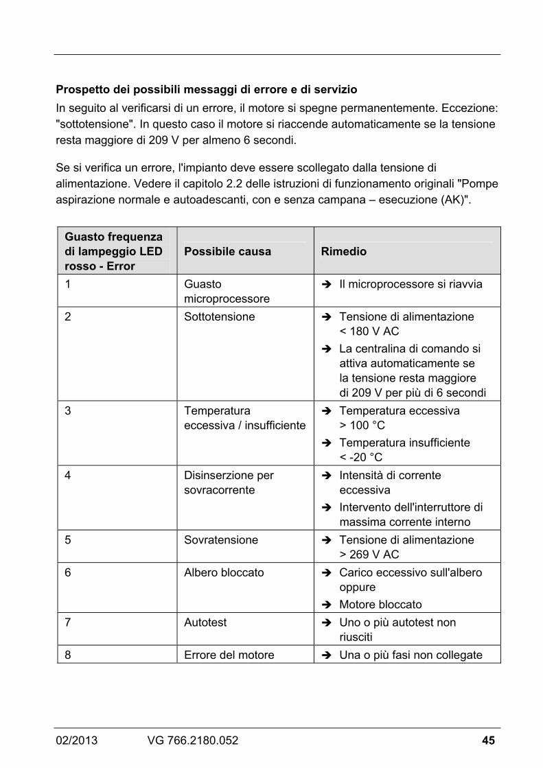
Prospetto dei possibili messaggi di errore e di servizio In seguito al verificarsi di un errore, il motore si spegne permanentemente. Eccezione: "sottotensione". In questo caso il motore si riaccende automaticamente se la tensione resta maggiore di 209 V per almeno 6 secondi.
Se si verifica un errore, l'impianto deve essere scollegato dalla tensione di alimentazione. Vedere il capitolo 2.2 delle istruzioni di funzionamento originali "Pompe aspirazione normale e autoadescanti, con e senza campana – esecuzione (AK)".
Guasto frequenza di lampeggio LED rosso - Error
Possibile causa Rimedio
1 Guasto microprocessore
Il microprocessore si riavvia
2 Sottotensione Tensione di alimentazione < 180 V AC
La centralina di comando si attiva automaticamente se la tensione resta maggiore di 209 V per più di 6 secondi
3 Temperatura eccessiva / insufficiente
Temperatura eccessiva > 100 °C
Temperatura insufficiente < -20 °C
4 Disinserzione per sovracorrente
Intensità di corrente eccessiva
Intervento dell'interruttore di massima corrente interno
5 Sovratensione Tensione di alimentazione > 269 V AC
6 Albero bloccato Carico eccessivo sull'albero oppure
Motore bloccato 7 Autotest Uno o più autotest non
riusciti 8 Errore del motore Una o più fasi non collegate
46 VG 766.2180.052 02/2013
Altri documenti applicabili Le istruzioni di funzionamento originali "Pompe aspirazione normale e autoadescanti, con e senza campana – esecuzione (AK)" fanno parte a questa documentazione pompa. Queste devono essere ben accessibili per il personale di servizio e per il personale di assistenza.

ES
02/2013 VG 766.2180.052 47
La bomba tiene un motor de imán permanente y está protegida electrónicamente contra sobrecarga.
Conexión de contactos de conmutación externos Para el mando externo la bomba tiene un cable de 5 hilos con cabos abiertos. Asignación de los cables a las velocidades de giro individuales de la siguiente manera:
Blanco = n 3Verde = n 2Marrón = n 1Rojo = Stop Negro = Toma de tierra
Los cables se tienen que conectar sin potencial. Conectar sólo individualmente los contactos, de lo contrario no se efectúa la activación de la velocidad de giro deseada.
GND
p.ej. reloj programadorde 3 canales con contactosde conmutación sin potencial
Nota Poner en marcha la velocidad del motor mediante botón pulsador o contactos de conmutación externos. De esta manera se activan los contactos de conmutación y la velocidad de giro asignada.
Arranca la bomba cuando está parada, a continuación la pone en marcha en el modo de aspiración.

48 VG 766.2180.052 02/2013
Durante el funcionamiento las velocidades fijas se aplican directamente, sin tiempo de aspiración.
Si el mando externo no se necesita, deben aislarse los cabos de cable.
Nota Se recomienda la instalación de un controlador de flujo en la circulación de la bomba para que puedan mostrarse los posibles mensajes de error. Esto permite que se pueda evitar una interrupción más prolongada del ciclo del agua de baño.

02/2013 VG 766.2180.052 49
Ajuste previo: Velocidad: 3 = 2830 min-1 2 = 2400 min-1 1 = 2000 min-1
Velocidad de aspiración: = 2830 min-1 Tiempo de aspiración: = 5 minutos
Velocidades ajustables: 1000 - 2830 min-1 (en pasos de 50 min-1) Tiempo de aspiración ajustable: 0 - 10 min. (en pasos de 1 min. )
Interfaz de usuario: (1) Display de LED: indica la actual velocidad
de giro del motor.
(2) Tecla "SET": para llegar al modo de programación o para reset del mando.
(3) Tecla "1/ ": para seleccionar la velocidad de giro fija / para cambiar en el modo de programación.
(4) Tecla "2/OK": para seleccionar la velocidad de giro fija / para el almacenamiento en el modo de programación.
(5) Tecla "3/ ": para seleccionar la velocidad de giro fija / para cambiar en el modo de programación.
(6) Tecla "0": para detener el motor.
1
2
5
6
3
4
50 VG 766.2180.052 02/2013
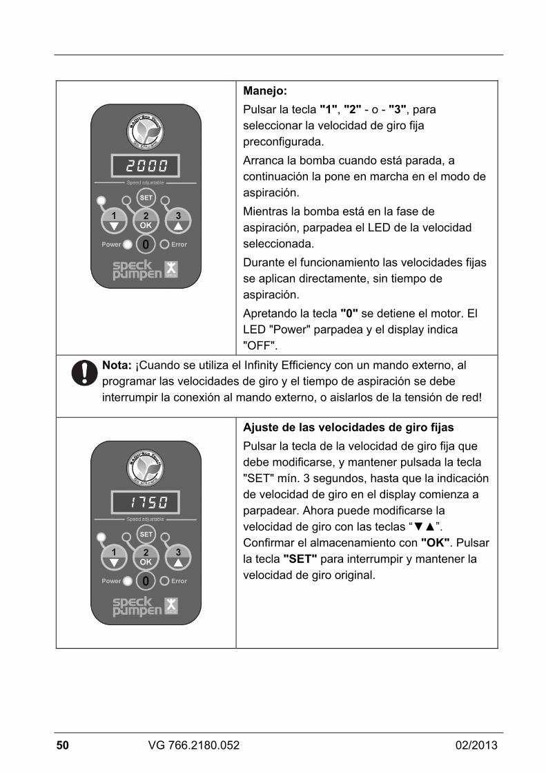
Manejo: Pulsar la tecla "1", "2" - o - "3", para seleccionar la velocidad de giro fija preconfigurada. Arranca la bomba cuando está parada, a continuación la pone en marcha en el modo de aspiración. Mientras la bomba está en la fase de aspiración, parpadea el LED de la velocidad seleccionada. Durante el funcionamiento las velocidades fijas se aplican directamente, sin tiempo de aspiración. Apretando la tecla "0" se detiene el motor. El LED "Power" parpadea y el display indica "OFF".
Nota: ¡Cuando se utiliza el Infinity Efficiency con un mando externo, al programar las velocidades de giro y el tiempo de aspiración se debe interrumpir la conexión al mando externo, o aislarlos de la tensión de red!
Ajuste de las velocidades de giro fijas Pulsar la tecla de la velocidad de giro fija que debe modificarse, y mantener pulsada la tecla "SET" mín. 3 segundos, hasta que la indicación de velocidad de giro en el display comienza a parpadear. Ahora puede modificarse la velocidad de giro con las teclas “▼▲”. Confirmar el almacenamiento con "OK". Pulsar la tecla "SET" para interrumpir y mantener la velocidad de giro original.

02/2013 VG 766.2180.052 51
Ajuste de los parámetros de aspiración Para programar el tiempo de aspiración debe estar parado el motor (tecla "0"). Luego pulsar otra vez la tecla "SET" durante mín. 3 segundos, hasta que la indicación de velocidad de giro en el display comienza a parpadear. Ahora puede ajustarse la velocidad de giro con la que el motor funcionará durante el tiempo de aspiración. Con las teclas “▼▲” puede modificarse y con "OK" almacenarse la velocidad de giro. Después que se ha ajustado la velocidad de aspiración, puede determinarse la duración del tiempo de aspiración. Ésta puede ajustarse de 0 (= Off) a 10 minutos.
Restaurar / Reset El motor puede asignarse de nuevo al estado de suministro pulsando la tecla "SET" durante mín. 15 segundos. El motor se detiene y los tres LEDs de velocidad de giro fija se iluminan.
52 VG 766.2180.052 02/2013
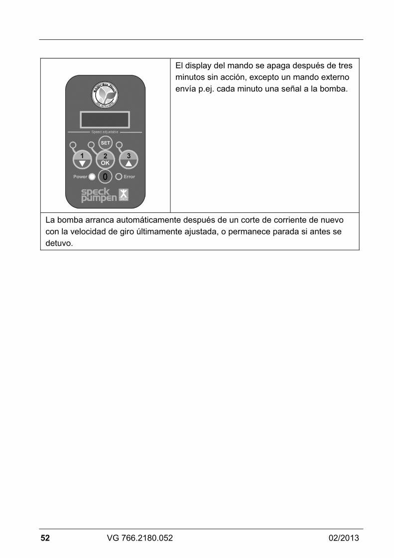
El display del mando se apaga después de tres minutos sin acción, excepto un mando externo envía p.ej. cada minuto una señal a la bomba.
La bomba arranca automáticamente después de un corte de corriente de nuevo con la velocidad de giro últimamente ajustada, o permanece parada si antes se detuvo.

02/2013 VG 766.2180.052 53
Presentación de posibles avisos de funcionamiento y mensajes de error Si se produjo un fallo, el motor se desconecta de forma permanente. Fallo excepcional: "Tensión insuficiente". En este caso, el motor se conecta automáticamente de nuevo cuando la tensión sobrepasa 209 V durante al menos 6 segundos.
Si se produce un fallo, la instalación se tiene que desconectar de la alimentación eléctrica. Ver capítulo 2.2 de las instrucciones originales para bombas de "Aspiración normal y bombas auto-aspirantes con/sin la versión (AK)".
LED de error rojo, parpadeos por fallo
Causa posible Remedio
1 Fallo de microprocesador
El microprocesador vuelve a iniciar
2 Tensión insuficiente Alimentación eléctrica < 180 V CA
El mando se activa automáticamente cuando la tensión sobrepasa 209 V durante más de 6 segundos
3 Temperatura demasiado alta / demasiado baja
Temperatura demasiado alta > 100 °C
Temperatura demasiado baja < -20 °C
4 Desconexión de corriente excesiva
Corriente demasiado alta Interruptor protector interno
de sobreintensidad conectado
5 Sobretensión Alimentación eléctrica > 269 V CA
6 Eje bloqueado Carga en el eje demasiado alta o
motor parado 7 Autoprueba Una o más autopruebas no
tienen éxito 8 Fallo de motor Una o más fases no están
conectadas

54 VG 766.2180.052 02/2013
Documentos incluidos En esta hoja de datos de la bomba se incluyen las instrucciones originales para bombas de "Aspiración normal y bombas auto-aspirantes con/sin la versión (AK)". Usted debe facilitar el libre acceso para el personal de operación y mantenimiento.

02/2013 VG 766.2180.052 55
56 VG 766.2180.052 02/2013
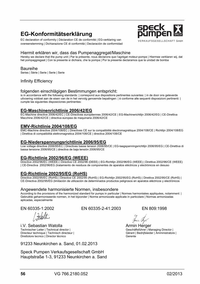
EG-Konformitätserklärung EC declaration of conformity | Déclaration CE de conformité | EG-verklaring van overeenstemming | Dichiarazione CE di conformità | Declaración de conformidad
Hiermit erklären wir, dass das Pumpenaggregat/Maschine Hereby we declare that the pump unit | Par la présente, nous déclarons que l’agrégat moteur-pompe | Hiermee verklaren wij, dat het pompaggregaat | Con la presente si dichiara, che la pompa | Por la presente declaramos que la unidad de bomba
Baureihe Series | Série | Serie | Serie | Serie
Infinity Efficiency
folgenden einschlägigen Bestimmungen entspricht: is in accordance with the following standards: | correspond aux dispositions pertinentes suivantes: | in de door ons geleverde uitvoering voldoet aan de eisen van de in het vervolg genoemde bepalingen: | è conforme alle sequenti disposizioni pertinenti: | cumple las siguientes disposiciones pertinentes:
EG-Maschinenrichtlinie 2006/42/EG EC-Machine directive 2006/42/EC | CE-Directives européennes 2006/42/CE | EG-Machinerichtlijn 2006/42/EG | CE-Direttiva Macchine 2006/42/CE | directiva europea de maquinaria 2006/42/CE
EMV-Richtlinie 2004/108/EG EMC-Machine directive 2004/108/EC | Directives CE sur la compatibilité électromagnétique 2004/108/CE | Richtlijn 2004/108/EG | Direttiva di compatibilità elettromagnetica 2004/108/CE | directiva 2004/108/CE
EG-Niederspannungsrichtlinie 2006/95/EG Low voltage directive 2006/95/EC | Directives basse tension 2006/95/CE | EG-laagspanningsrichtlijn 2006/95/EG | CE-Direttiva di bassa tensione 2006/95/CE | directiva de baja tensión 2006/95/CE
EG-Richtlinie 2002/96/EG (WEEE) Directive 2002/96/EC (WEEE) | Directive CE 2002/96 (DEEE) | EG-Richtlijn 2002/96/EG (WEEE) | Direttiva 2002/96/CE (WEEE) | CE-Directiva 2002/96/EG (tratamiento de residuos de componentes de aparatos eléctricos y electrónicos en desuso
EG-Richtlinie 2002/95/EG (RoHS) Directive 2002/95/EC (RoHS) | Directive CE 2002/95 (RoHS) | EG-Richtlijn 2002/95/EG (RoHS) | Direttiva 2002/95/CE (RoHS) | CE-Directiva 2002/95/EG (limitación de utilización de determinados productos peligrosos en aparatos eléctricos y electrónicos
Angewendete harmonisierte Normen, insbesondere According to the provisions of the harmonized standard for pumps in particular | Normes harmonisées appliquées, notamment: | Gebruikte geharmoniseerde normen, in het bijzonder | Norme armonizzate applicate in particolare | Normas armonizadas aplicadas, especialmente
EN 60335-1:2002 EN 60335-2-41:2003 EN 809:1998
i.V. Sebastian Watolla Armin Herger Technischer Leiter | Technical director | Geschäftsführer | Managing Director | Directeur technique | Technisch directeur | Gérant | Bedrijfsleider | Amministratore | Direttotore tecnico | Director técnico Gerente 91233 Neunkirchen a. Sand, 01.02.2013 Speck Pumpen Verkaufsgesellschaft GmbH Hauptstraße 1-3, 91233 Neunkirchen a. Sand


![LQJ FWPc RP] h^d S^ XU h^d UX]S P bRaTf X] h^da bcTf](https://img.pdfslide.us/doc/110x75/5f0fa0d47e708231d4451b48/-lqj-fwpc-rp-hd-s-xu-hd-uxs-p-bratf-x-hda-bctf-.jpg)