Embed Size (px)
Citation preview
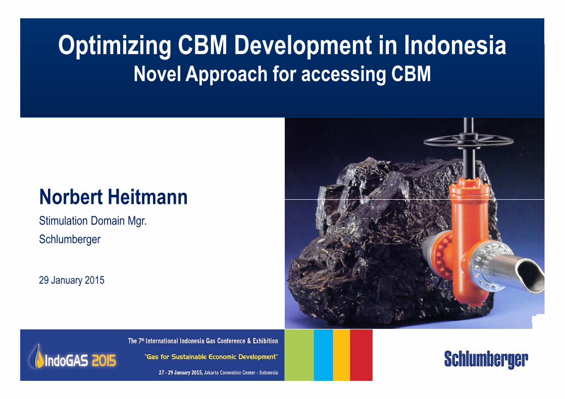
Norbert Heitmann
Optimizing CBM Development in IndonesiaNovel Approach for accessing CBM
Norbert HeitmannStimulation Domain Mgr.
Schlumberger
29 January 2015
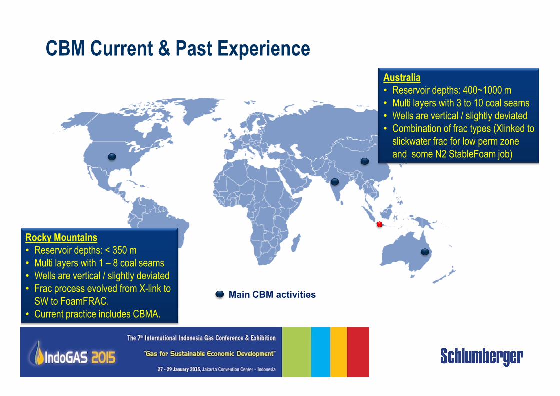
CBM Current & Past Experience
Australia
• Reservoir depths: 400~1000 m
• Multi layers with 3 to 10 coal seams
• Wells are vertical / slightly deviated
• Combination of frac types (Xlinked to
slickwater frac for low perm zone
and some N2 StableFoam job)
Main CBM activities
Rocky Mountains
• Reservoir depths: < 350 m
• Multi layers with 1 – 8 coal seams
• Wells are vertical / slightly deviated
• Frac process evolved from X-link to
SW to FoamFRAC.
• Current practice includes CBMA.
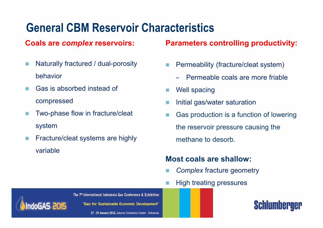
Coals are complex reservoirs:
� Naturally fractured / dual-porosity
behavior
� Gas is absorbed instead of
compressed
� Two-phase flow in fracture/cleat
General CBM Reservoir CharacteristicsParameters controlling productivity:
� Permeability (fracture/cleat system)
– Permeable coals are more friable
� Well spacing
� Initial gas/water saturation
� Gas production is a function of lowering � Two-phase flow in fracture/cleat
system
� Fracture/cleat systems are highly
variable
� Gas production is a function of lowering
the reservoir pressure causing the
methane to desorb.
Most coals are shallow:
� Complex fracture geometry
� High treating pressures
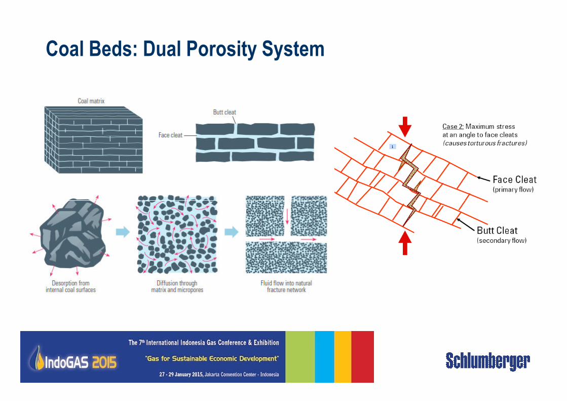
Coal Beds: Dual Porosity System
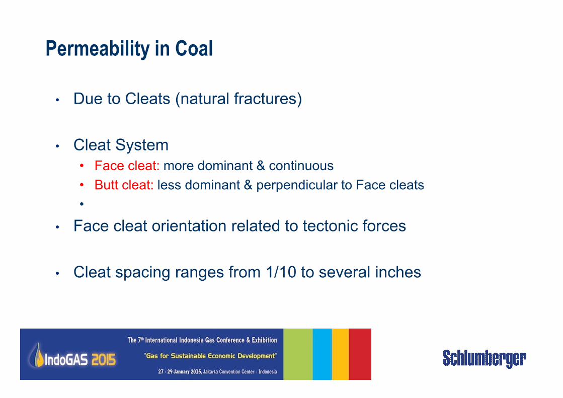
Permeability in Coal
• Due to Cleats (natural fractures)
• Cleat System
• Face cleat: more dominant & continuous
• Butt cleat: less dominant & perpendicular to Face cleats
••
• Face cleat orientation related to tectonic forces
• Cleat spacing ranges from 1/10 to several inches
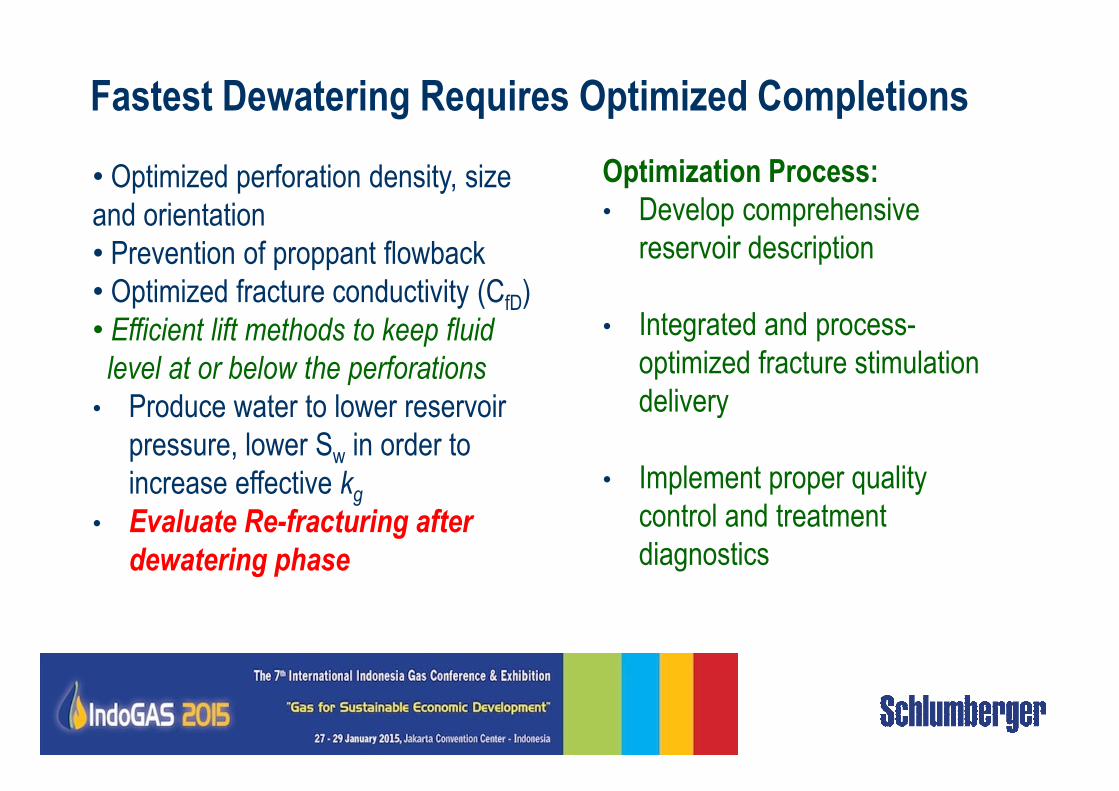
Fastest Dewatering Requires Optimized Completions
• Optimized perforation density, size
and orientation
• Prevention of proppant flowback
• Optimized fracture conductivity (CfD)
• Efficient lift methods to keep fluid
level at or below the perforations
• Produce water to lower reservoir
Optimization Process:
• Develop comprehensive
reservoir description
• Integrated and process-
optimized fracture stimulation
delivery• Produce water to lower reservoir
pressure, lower Sw in order to
increase effective kg
• Evaluate Re-fracturing after
dewatering phase
delivery
• Implement proper quality
control and treatment
diagnostics
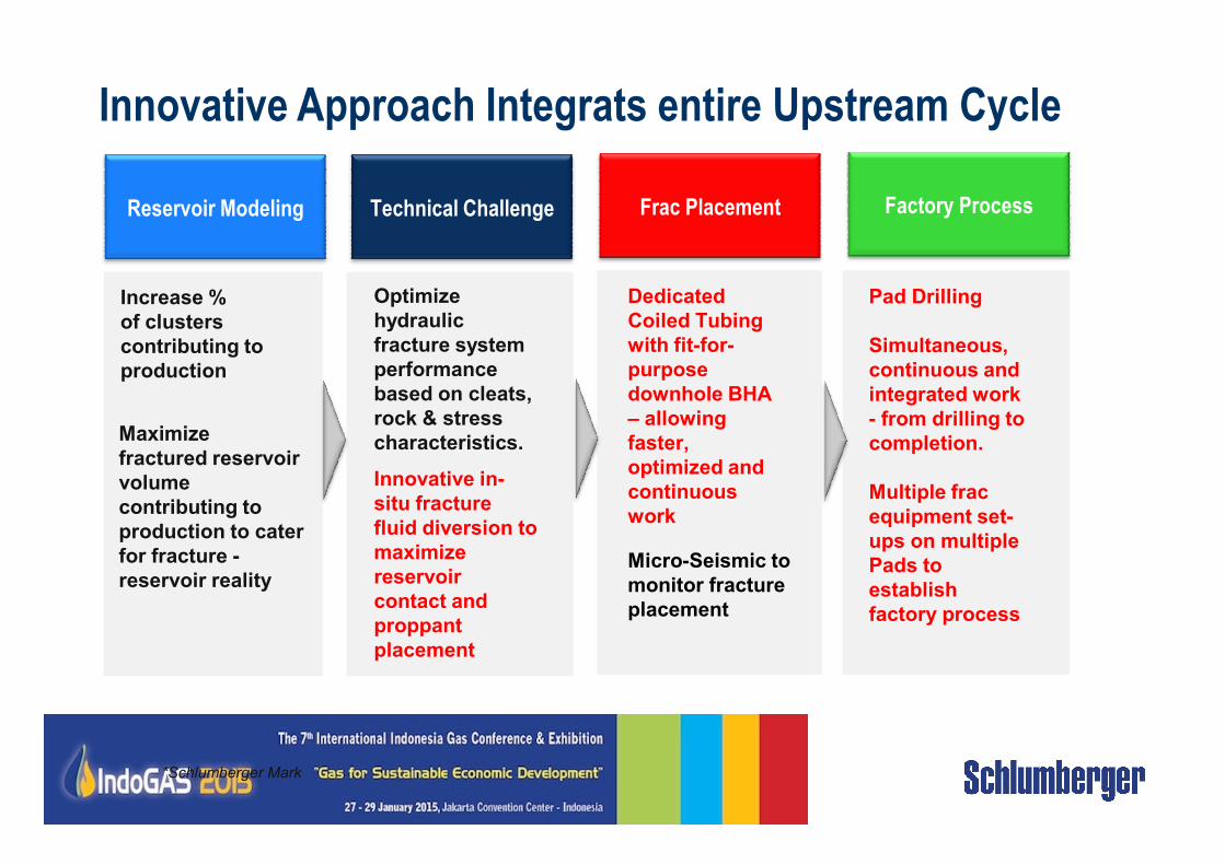
Innovative Approach Integrats entire Upstream Cycle
Technical ChallengeReservoir Modeling
Increase %
of clusters
contributing to
production
Maximize
Optimize
hydraulic
fracture system
performance
based on cleats,
rock & stress
characteristics.
Frac Placement Factory Process
Dedicated
Coiled Tubing
with fit-for-
purpose
downhole BHA
– allowing
faster,
Pad Drilling
Simultaneous,
continuous and
integrated work
- from drilling to
completion.Maximize
fractured reservoir
volume
contributing to
production to cater
for fracture -
reservoir reality
characteristics.
Innovative in-
situ fracture
fluid diversion to
maximize
reservoir
contact and
proppant
placement
*Schlumberger Mark
faster,
optimized and
continuous
work
Micro-Seismic to
monitor fracture
placement
completion.
Multiple frac
equipment set-
ups on multiple
Pads to
establish
factory process
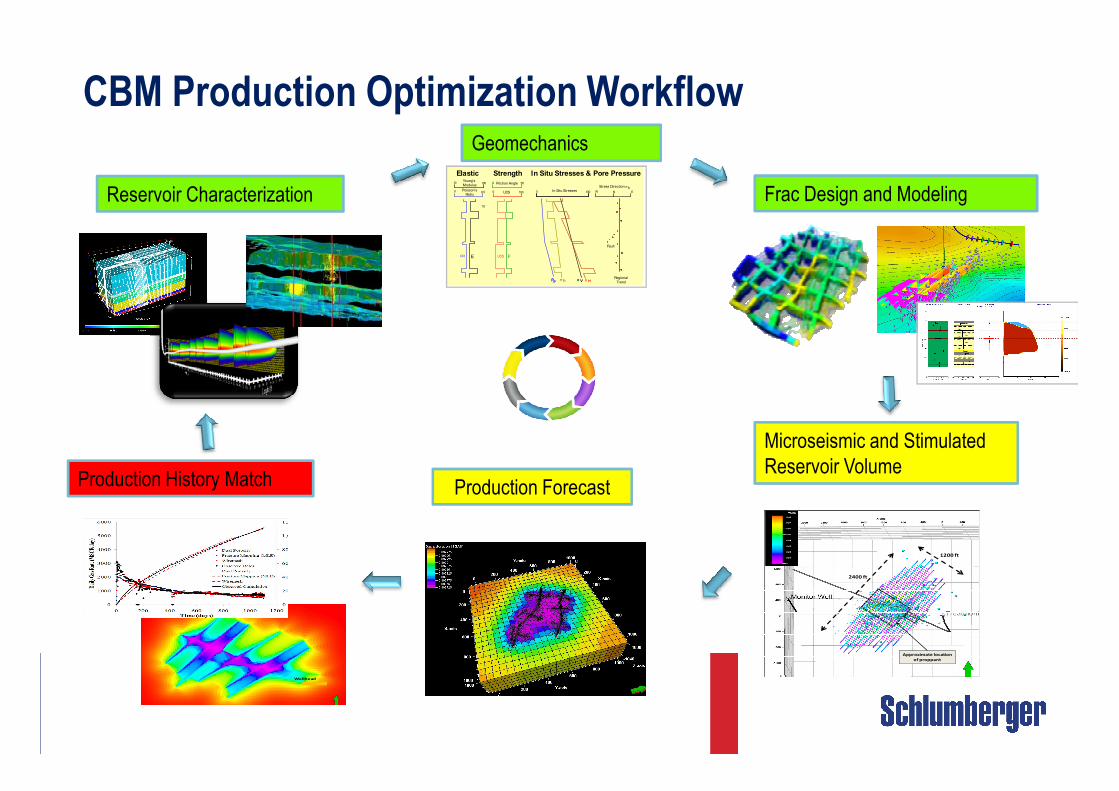
CBM Production Optimization Workflow
Reservoir Characterization Frac Design and Modeling
Geomechanics
Strength
UCS F
0 100
0 50
UCS
Friction Angle
In Situ Stresses & Pore Pressure
Pp σ h σ Hσ V
0 100In Situ Stresses W N E
Stress Direction σh
Fault
Regional
Trend
PR E
0.5Poisson’s
Ratio
Young’s
Modulus100
Elastic
1.0
0
10
Strength
UCS F
0 100
0 50
UCS
Friction Angle
In Situ Stresses & Pore Pressure
PpPp σ hσ h σ Hσ Hσ Vσ V
0 100In Situ Stresses W N E
Stress Direction σh
Fault
Regional
Trend
PR E
0.5Poisson’s
Ratio
Young’s
Modulus100
Elastic
1.0
0
10
Production Forecast
Microseismic and Stimulated
Reservoir Volume
2400 ft
1200 ft
Approximate location
of proppant
2400 ft
1200 ft
Approximate location
of proppant
Production History Match
Fracture Plane Extraction Approach
Wellhead
Fracture Plane Extraction Approach
Wellhead
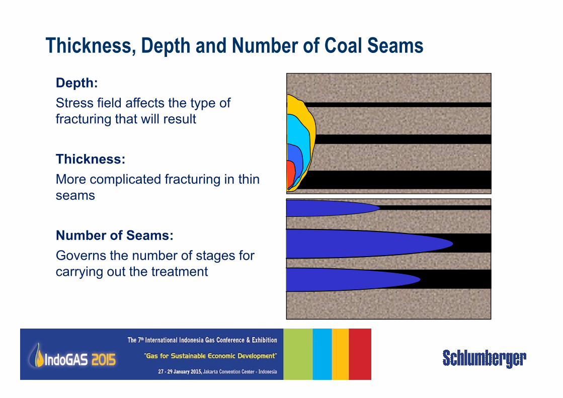
Thickness, Depth and Number of Coal Seams
Depth:
Stress field affects the type of
fracturing that will result
Thickness:
More complicated fracturing in thin
seamsseams
Number of Seams:
Governs the number of stages for
carrying out the treatment
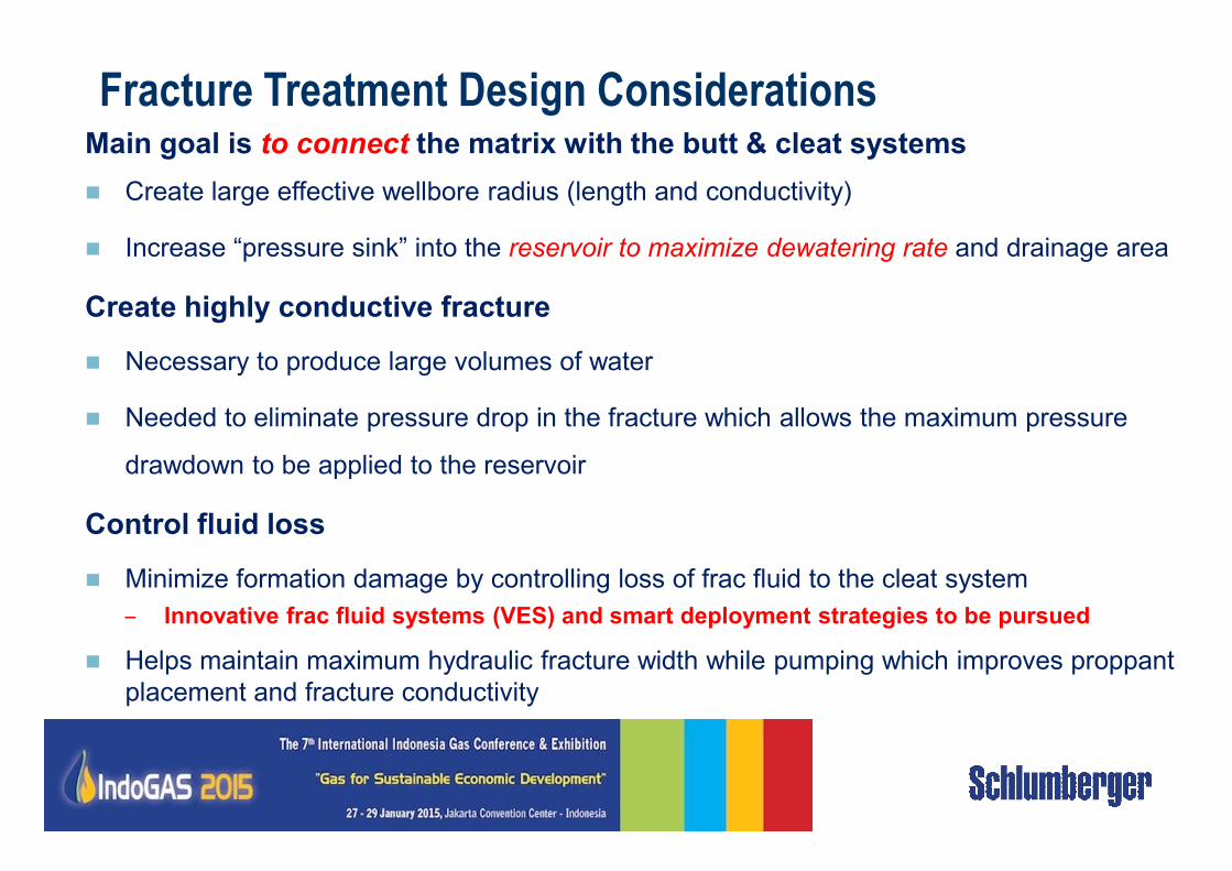
Fracture Treatment Design ConsiderationsMain goal is to connect the matrix with the butt & cleat systems
� Create large effective wellbore radius (length and conductivity)
� Increase “pressure sink” into the reservoir to maximize dewatering rate and drainage area
Create highly conductive fracture
� Necessary to produce large volumes of water
� Needed to eliminate pressure drop in the fracture which allows the maximum pressure
drawdown to be applied to the reservoir
Control fluid loss
� Minimize formation damage by controlling loss of frac fluid to the cleat system
– Innovative frac fluid systems (VES) and smart deployment strategies to be pursued
� Helps maintain maximum hydraulic fracture width while pumping which improves proppant
placement and fracture conductivity
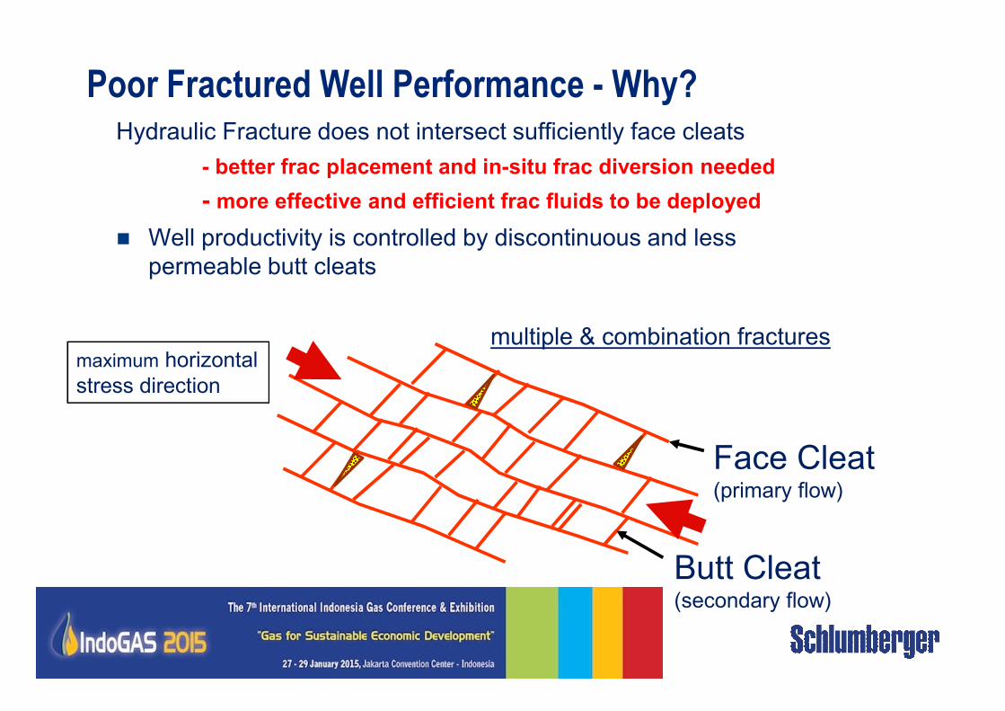
Poor Fractured Well Performance - Why?
multiple & combination fracturesmaximum horizontal
Hydraulic Fracture does not intersect sufficiently face cleats
- better frac placement and in-situ frac diversion needed
- more effective and efficient frac fluids to be deployed
� Well productivity is controlled by discontinuous and less
permeable butt cleats
Butt Cleat(secondary flow)
Face Cleat(primary flow)
maximum horizontal
stress direction
Cementing Considerations & Requirements
• Formation damage from the cement slurry can be more damaging
than drilling
• This impairment can be minimized with properly designed light
weight systems
• Traditional solution is the application of low density cement
systems to reduce the hydrostatic pressure of the cement columnsystems to reduce the hydrostatic pressure of the cement column
• Requirements of the slurry are more than just density reduction:
• Slurry must create seal to prevent annular flow of fluids (low permeability).
• Slurry must have adequate compressive strength to maintain bond integrity
• Whole slurry loss into the cleat structure must be minimized
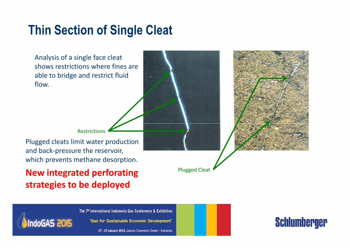
Thin Section of Single Cleat
Analysis of a single face cleat
shows restrictions where fines are
able to bridge and restrict fluid
flow.
Restrictions
Plugged Cleat
Plugged cleats limit water production
and back-pressure the reservoir,
which prevents methane desorption.
New integrated perforating
strategies to be deployed
Coal Bed Methane Additive: CBMA™
Designed specifically for the unique properties of coal reservoirs
• Non-ionic surfactant solution adsorbs on coal surfaces
• Lowers surface tension of the water around the coal surfaces
• Maintain the natural wettability of the coal surface
• Enhance the ability of the coal to dewater – increases permeability of coal to water
• Minimize fines movement through the cleat system. Repels water from fines
• Operationally easy as add to frac fluid
• Economical
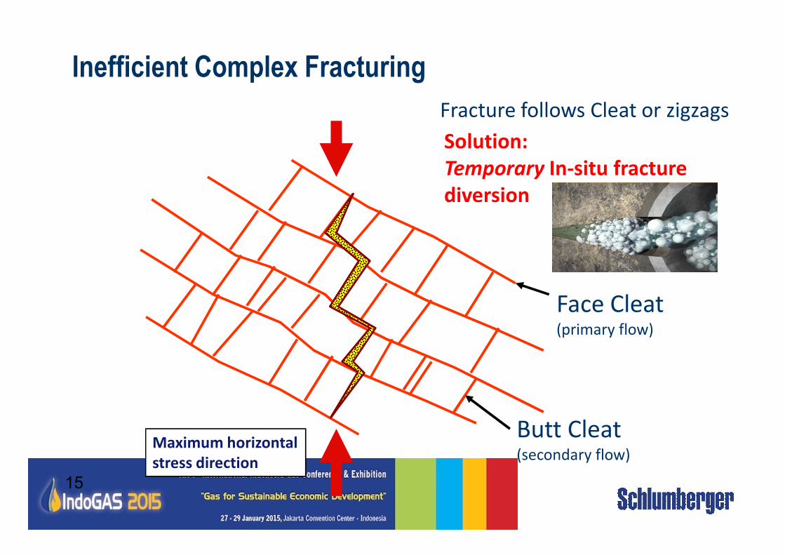
Inefficient Complex Fracturing
Fracture follows Cleat or zigzags
Solution:
Temporary In-situ fracture
diversion
15
Butt Cleat(secondary flow)
Face Cleat(primary flow)
Maximum horizontal
stress direction
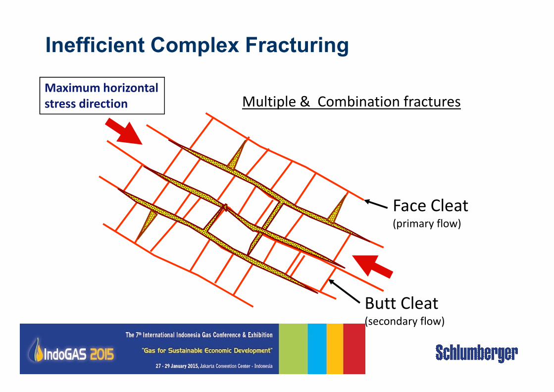
Inefficient Complex Fracturing
Face Cleat
Multiple & Combination fracturesMaximum horizontal
stress direction
Butt Cleat(secondary flow)
Face Cleat(primary flow)
• It is difficult to generate long fracture half-length in coal seam
reservoirs
• Single, vertical fractures intersecting multiple coal seams
• Single, vertical fracture contained in a single coal seam (common
in thicker coal seams (>20 ft).
Fracture Geometry in Coal
• Innovation:
• Fracture intercepts seams from near-by wells (vertical and
horizontal wells)
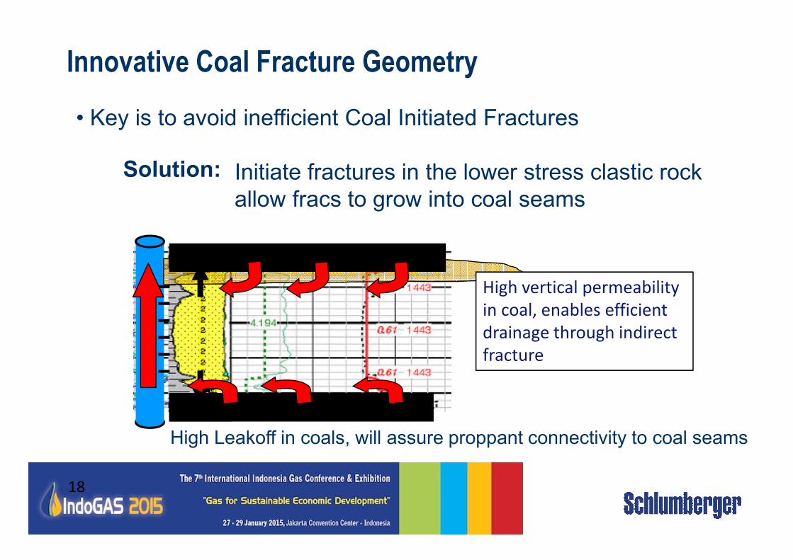
Innovative Coal Fracture Geometry
• Key is to avoid inefficient Coal Initiated Fractures
Solution: Initiate fractures in the lower stress clastic rock
allow fracs to grow into coal seams
High vertical permeability
18
High Leakoff in coals, will assure proppant connectivity to coal seams
High vertical permeability
in coal, enables efficient
drainage through indirect
fracture
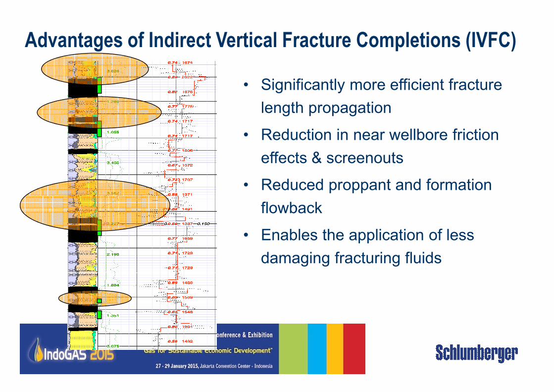
Advantages of Indirect Vertical Fracture Completions (IVFC)
• Significantly more efficient fracture
length propagation
• Reduction in near wellbore friction
effects & screenouts
• Reduced proppant and formation
flowback
• Enables the application of less
damaging fracturing fluids
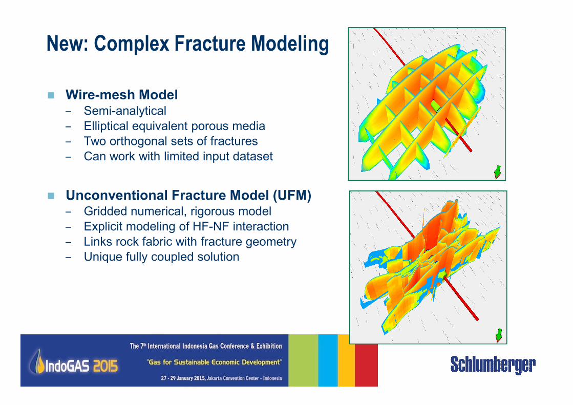
New: Complex Fracture Modeling
� Wire-mesh Model– Semi-analytical
– Elliptical equivalent porous media
– Two orthogonal sets of fractures
– Can work with limited input dataset
� Unconventional Fracture Model (UFM)Unconventional Fracture Model (UFM)– Gridded numerical, rigorous model
– Explicit modeling of HF-NF interaction
– Links rock fabric with fracture geometry
– Unique fully coupled solution
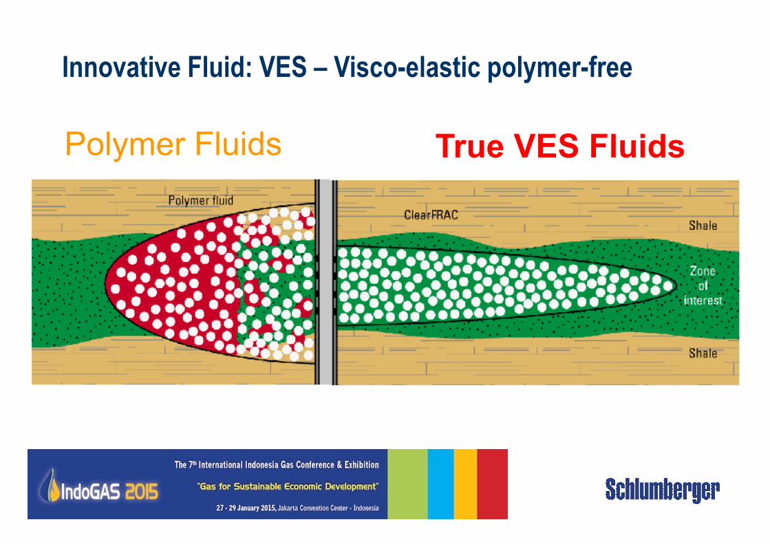
Polymer Fluids True VES Fluids
Innovative Fluid: VES – Visco-elastic polymer-free
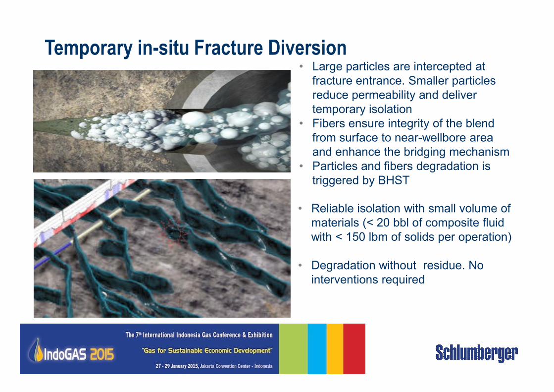
BroadBand Sequence - Enablers • Large particles are intercepted at
fracture entrance. Smaller particles
reduce permeability and deliver
temporary isolation
• Fibers ensure integrity of the blend
from surface to near-wellbore area
and enhance the bridging mechanism
• Particles and fibers degradation is
triggered by BHST
Temporary in-situ Fracture Diversion
• Reliable isolation with small volume of
materials (< 20 bbl of composite fluid
with < 150 lbm of solids per operation)
• Degradation without residue. No
interventions required
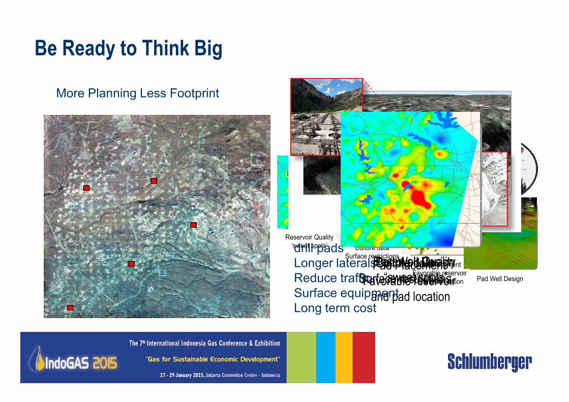
Be Ready to Think Big
FDP
Integrating it All Together
More Planning Less Footprint
Culture data
Surface restrictionsPad Placement
Favorable reservoir
and pad location
Pad Well Design
Reservoir Quality
‘sweet spots’ Culture data
Surface restrictions
Pad Placement
Favorable reservoir
and pad location Pad Well Design
drill pads
Longer laterals
Reduce traffic
Surface equipment
Long term cost
Reservoir Quality
“sweet spots”
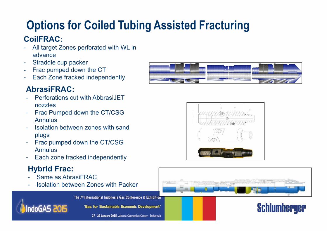
Options for Coiled Tubing Assisted FracturingCoilFRAC:- All target Zones perforated with WL in
advance
- Straddle cup packer
- Frac pumped down the CT
- Each Zone fracked independently
AbrasiFRAC:- Perforations cut with AbbrasiJET
nozzles
- Frac Pumped down the CT/CSG - Frac Pumped down the CT/CSG
Annulus
- Isolation between zones with sand
plugs
- Frac pumped down the CT/CSG
Annulus
- Each zone fracked independently
Hybrid Frac:- Same as AbrasiFRAC
- Isolation between Zones with Packer
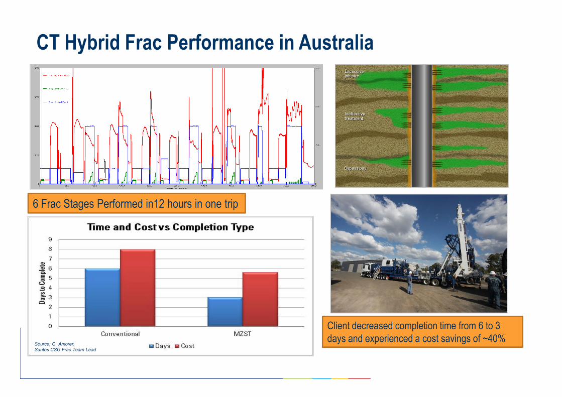
CT Hybrid Frac Performance in Australia
6 Frac Stages Performed in12 hours in one trip6 Frac Stages Performed in12 hours in one trip
Client decreased completion time from 6 to 3
days and experienced a cost savings of ~40%Source: G. Amorer,
Santos CSG Frac Team Lead
Conclusions & Outlook
- Functional business model needed to get it going & to get it right
- Commitment and partnering-up among all players
- Factory Drilling and Hydraulic Fracturing to optimize & maximize
production
- New innovative and fully integrated Coiled Tubing assisted fracturing is a
26
- New innovative and fully integrated Coiled Tubing assisted fracturing is a
viable option for development of CBM
- The success of a project of this magnitude will be depend on the
efficiency of the overall process and a commercial model that promotes a
sustainable scenario for the operators and the service provider.
- Fit for purpose equipment, fluids and techniques will bring success