Embed Size (px)
Citation preview

Observations: • Score marks along the contact surfaces of the rotor
(sealing line)
Causes: • Solids traveling through the pump, worsen with
internal leakage (sand, iron pyrite, casing cement, coal...)
PCP FAILURE MODEOBSERVATIONS, CAUSES & SOLUTIONS
keep it moving
Solutions: • Review space out calculation and on site proper realization• Ensure pup joint selection (ID and length) is adapted to pump geometry and operating conditions.
ROTOR FAILURE MODE
Solutions: • Select pump geometry adapted to solid management (short pitch, low swept angle)• Adapt rotor size to reduce internal leakage with tighter rotor/stator fit (bigger rotor)• Optimize pump setting depth, as solid ratio at pump intake is directly linked to pump position vs
perforation
Note: see also stator abrasion section.
� WORN ROTOR: ABRASION
� WORN ROTOR: METAL CONTACT
Observations: • Surface coating of the rotor is worn down to the base
metal. • Flat surface on helicoidal line.
Causes: • Friction against the tubing (too high space out or too
short pup joint)• Friction against the pup joint (diameter too small)• Friction against naked stator wall (loss of elastomer)• Top part of parted rotor above stator knocking inside
the pup joint and/or tubing
Note: difference between abrasion and metal/metal wear: abrasion wear is round on sealing line while metal/metal wear generate a flat surface on sealing line.

PCP failure mode
Artificial Lift Solutions
Solutions: • Operate the pump at speed that warranty a minimum of fluid at intake (regular monitoring of fluid level) • Set the pump deeper
Note: This rotor damage may not affect pump efficiency.
� CHROMIUM CRACKED / HEAT CRACKED
Observations: • Checkered pattern of rotor coating, located at rotor
contact surfaces• Rotor crest is brighter than on the valley, due to heat
Causes: • Lack of fluid at pump intake (well pump off or
plugged intake)• Long slug of free gas traveling through the pump
Solutions: • Remove completely rotor from well during acid job and circulate water before re run in hole
� PITTED ROTOR
Observations: • Small pitting or rusted area on surface coating,
usually in an erratic pattern.
Causes: • Presence of a corrosive substance in the well (Acid
job, CO2, H2S, others...). To be confirmed with pH level of produced fluid.
Solutions: • Monitor pH of fluid• Flush well with clear water to get pH between 6 and 8.
� CHEMICAL ATTACK
Observations: • Most of the chromium layer is removed and base
metal is chemically attacked
Causes: • Acid jobs with rotor in place or without proper
washing after injection is the major cause of this failure.

PCP failure mode
Artificial Lift Solutions
Solutions: • If stick and slip effect: increase speed (downsizing the pump) or upsize torsional stiffness (rod size
increase)• Optimize the pump setting depth by landing it at recommended DLS• If high differential pressure: review PCM design to challenge PCP model selection• If solid accumulation: limit quantity of start & stop, flush the pump regularly & systematically after a stop
and before restart, optimize pump setting depth, as solid ratio at pump intake is directly linked to the pump position vs perforation
• If low space out: review space out calculation and on site proper realization
� BROKEN ROTOR: TORSION
Observations: • Rough jagged surface throughout the majority of the
rotor cross-section. • No visible pattern is made.• Generally broke in the first 2ft below rotor head or
just below the rotor head.
Causes: • High amounts of torsional/bending stress put on the
rotor (stick & slip effect at low speed, high deviation, high differential pressure)
• Solids entering the pump and blocked between rotor and stator.
• Too low space out: end part of rotor touching the tag bar and conducting to increase torque, up to rotor failure just below the head.
• Excessive swelling of the stator elastomer
Solutions: • If high space out: review space out calculation and on site proper realization• Reduce PCP speed (upsize the pump) • Optimize pump setting depth by landing it at recommended DLS • If stick and slip effect: increase speed (downsizing the pump) , or upsize torsional stiffness (rod size
increase)
� BROKEN ROTOR: FATIGUE
Observations: • Characterized by a flat, smooth surface across the
majority of the cross sectional area of the rotor.• A small section may be rough and jagged. Beach
lines will be present.
Causes: Important and/or durable stress cycle (rotation and/or flexion) on the rotor possibly due to:
• operating rotor too far above stator (too high space out increase flexion)
• long run life at high speeds.• landing pump in highly deviated section of well.• a continuous torque and release of the pump (stick
and slip effect).

PCP failure mode
Artificial Lift Solutions
Observations: • The elastomer is brittle and hardened. (While
performing a transversal cut, it is observed a hardening of the elastomer, generally @ 1/3 of the teeth.)
• Cracks in minor diameter (maximum elastomer thickness)
• Debonding can be observed.
Causes: Hysteresis is the result of energy accumulation due to insufficient heat dissipation. Heat accumulation conduct to over vulcanization that transform Nitrile elastomer to ebonite.
This is generally the result of excessive stress due to one or combination of several parameters :
• Excessive pressure versus pump head or per cavities (improper internal pressure distribution)• Excessive Swelling• High temperature• Improper rotor sizing• Excessive speed
ELASTOMER STATOR FAILURE MODE
Solutions: • If high differential pressure: review PCM design to challenge PCP model selection• If excessive swelling: conduct a swelling test and adjust elastomer selection and rotor size if needed• If high temperature: make sure that the elastomer is compatible with the downhole temperature and
adjust rotor sizing• If excessive speed: upsize pump model
� HYSTERESIS
Observations: • Elastomer is rough and hardened on contact
surface (orange skin).
Causes: • Not enough fluid to dissipate friction heat due to
pump off condition or long gas slugs or fillage issue (viscous oil in small ID tail pipe) or plugged intake by solids
Solutions: • Operate the pump at speed that warranty a minimum of fluid at intake (regular monitoring of fluid level) • Ensure cavity filling by limiting flow restrictions at intake (increase ID of tail pipe, install top bushing)• Set the pump deeper
� DRY RUNNING
PCP failure mode
Artificial Lift Solutions
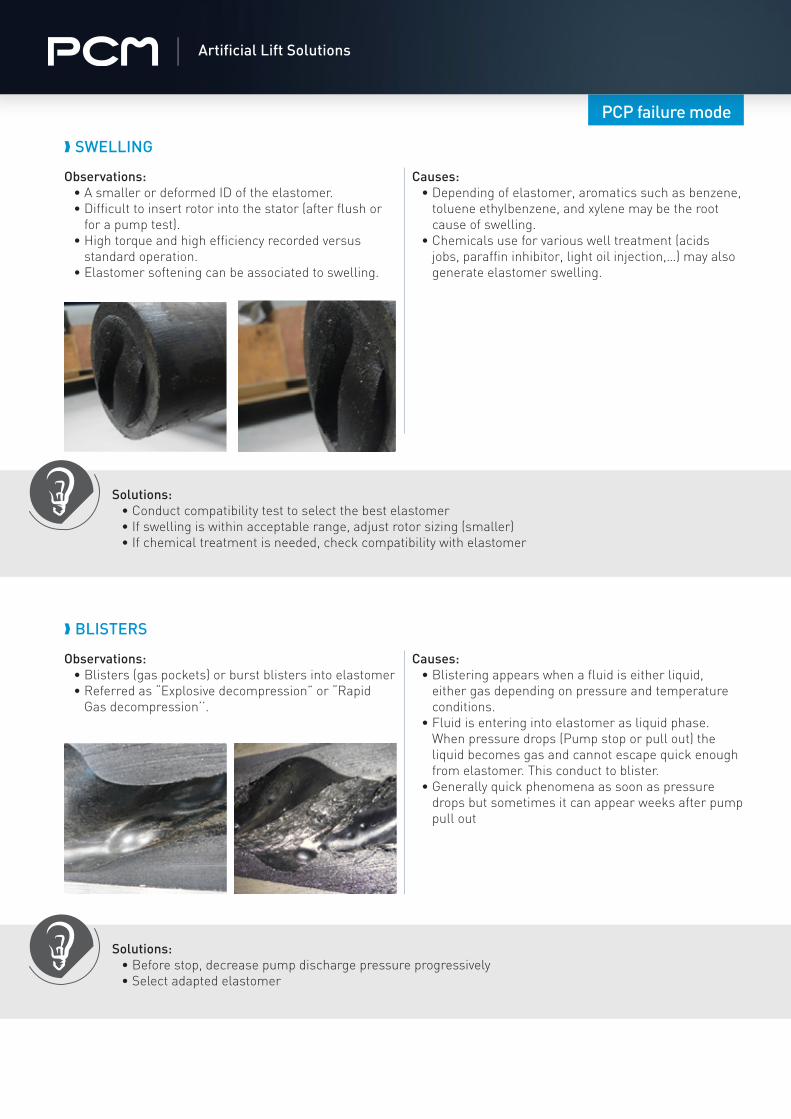
Solutions: • Conduct compatibility test to select the best elastomer• If swelling is within acceptable range, adjust rotor sizing (smaller)• If chemical treatment is needed, check compatibility with elastomer
� SWELLING
Observations: • A smaller or deformed ID of the elastomer.• Difficult to insert rotor into the stator (after flush or
for a pump test). • High torque and high efficiency recorded versus
standard operation. • Elastomer softening can be associated to swelling.
Causes: • Depending of elastomer, aromatics such as benzene,
toluene ethylbenzene, and xylene may be the root cause of swelling.
• Chemicals use for various well treatment (acids jobs, paraffin inhibitor, light oil injection,…) may also generate elastomer swelling.
Solutions: • Before stop, decrease pump discharge pressure progressively• Select adapted elastomer
� BLISTERS
Observations: • Blisters (gas pockets) or burst blisters into elastomer• Referred as “Explosive decompression” or “Rapid
Gas decompression’’.
Causes: • Blistering appears when a fluid is either liquid,
either gas depending on pressure and temperature conditions.
• Fluid is entering into elastomer as liquid phase. When pressure drops (Pump stop or pull out) the liquid becomes gas and cannot escape quick enough from elastomer. This conduct to blister.
• Generally quick phenomena as soon as pressure drops but sometimes it can appear weeks after pump pull out

PCP failure mode
Artificial Lift Solutions
Solutions: • Adapt elastomer and glue selection to downhole temperature• Check chemicals compatibility with elastomer & glue
� DEBONDED ELASTOMER
Observations: • Torn elastomer in long intact pieces• The inner steel wall is clean of any elastomer (bond
failure between stator housing and glue)• The inner steel wall is cover by a thin black layer of
elastomer (bond failure between glue and elastomer)• The inner steel wall is cover by a black layer of
elastomer (elastomer failure, such failure mode should not be considered as debonding)
• Usually associated with short run life
Causes: • Extreme heat in the pump.• Chemical attack.• Manufacturing defect (wrong metal housing rugosity,
poor surface cleaning before glue application, wrong uniformity and thickness of glue layer)
Solutions: • If high differential pressure: review PCM design to challenge PCP model selection • If solids : install a perforated tail joint at the intake• If pump off issue:
- Operate pump at speed that warranty a minimum of fluid at intake (regular monitoring of fluid level) - Ensure cavity filling by limiting flow restrictions at intake (increase ID of tail pipe, install top bushing)- Set the pump deeper
� MISSING ELASTOMER (TORN)
Observations: • Large pieces of elastomer missing from the stator. • “High pressure jetting” marks are sometime
associated
Causes: • Excessive elastomer stress due to:
- Exceeding pressure rating of pump (mainly at discharge)
- Solids traveling through the pump (bottom of stator)
- Pump Off (+hard elastomer)• Manufacturing defect (stator elements
synchronization issue or elastomer injection process).

PCP failure mode
Artificial Lift Solutions
Solutions: • If high differential pressure: review PCM design to challenge PCP model selection • Limit the internal leakage by rotor and/or pump geometry selection
� HIGH PRESSURE JETTING
Observations: • Worm-like grooves cut in the direction opposite to the
flow
Causes: • High pressure fluid slipping (backflow) within the
pump.• Over-pressuring of the pump.• Pump with low efficiency usually combined with low
fluid viscosity.
Solutions: • Select soft elastomer and tight stator/rotor fit• Select adapted PCP geometry that facilitate pushing vs crushing of solids
� STATOR ABRASION
Observations: • Score marks along the contact surfaces• Marks are typically perpendicular to the length of the
stator
Causes: • Solids traveling through the pump (sand, iron pyrite,
casing cement, coal, etc.)• High speeds will increase severity of damage
Solutions: • Review space out calculation and on site proper realization
� ROTOR HEAD RUNNING IN STATOR
Observations: • Wear on the rotor head will be visible. • The top of the stator will be damaged.• Tag bar could be also damaged.
Causes: • Usually caused by improper space-out.

PCP failure mode
Artificial Lift Solutions
Observations: • Deformed parts of the profile (bump)• Cracks or broken parts of the profile• Generally associated with parted rods due to sudden
torque increase
Causes: • Solids traveling through the pump (sand, iron pyrite,
casing cement, coal, etc.)
PCM VULCAIN™ STATOR FAILURE MODE
� FOREIGN ELEMENT
Solutions: • Install a perforated tail joint at intake
Observations: • General wear along the profile• Generally associated with low efficiency & wear on
the rotor
Causes: • Solids traveling through the pump (sand, iron pyrite,
casing cement, coal, etc.)• Low lubrication (high water cut)
� WEARING
Solutions: • Install a perforated tail joint at intake
For further information, please contact your PCM local representative :
www.pcmals.comArtificial Lift Solutions
Inde
x A
- O
ctob
er 2
019