Embed Size (px)
Citation preview

Trend Control Systems Ltd PO Box 34 Horsham Sussex RH12 2YF Tel: +44 (0) 1403 211888 Fax: +44 (0) 1403 241608 www.trend-controls.com
Trend PCO Tool Manual
Issue 1/A dd/mm/yy
Part No: TExxxxxx
CONTENTS
PCO Tool Manual TExxxxxx 1/A dd/mm/yy2
Copyright: Trend Control Systems Limited
Horsham, W. Sussex
All rights reserved. This manual contains proprietary information which is protectedby copyright. No part of this manual may be reproduced, transcribed, stored in aretrieval system, translated into any language or computer language, or transmitted inany form whatsoever without the prior consent of the publisher.
For information contact:
Trend Control Systems Limited
P.O. Box 34
Horsham
W. Sussex RH12 2YF
NOTICE: Trend Control Systems Limited makes no representations or warranties ofany kind whatsoever with respect to the contents hereof and specifically disclaims anyimplied warranties of merchantability or fitness for any particular purpose. TrendControl Systems Limited shall not be liable for any errors contained herein or forincidental or consequential damages in connection with the furnishing, performance oruse of this material. Trend Control Systems Limited reserves the right to revise thispublication from time to time and make changes in the content hereof withoutobligation to notify any person of such revisions or changes.
Microsoft Windows 95©, Microsoft Windows 98©, and Microsoft Windows NT© areregistered trademarks of the Microsoft Corporation.
CONTENTS
PCO Tool Manual Texxxxxx Issue 1/A dd/mm/yy 3
CONTENTS1 ABOUT THIS MANUAL ................................................................................. 51.1 Conventions Used in this Manual........................................................................ 51.2 Contacting Trend................................................................................................. 62. ABOUT THE PCO TOOL ............................................................................... 73 INSTALLATION .............................................................................................. 93.1 Obtain a Valid Licence........................................................................................ 93.2 Licence the PCO Tool ....................................................................................... 104. THE PCO TOOL WINDOW ......................................................................... 115 ENGINEER A PCO INTERFACE ................................................................ 135.1 Obtain the Necessary Files ................................................................................ 135.2 Create the .CDE file .......................................................................................... 135.3 Load the .CDE File............................................................................................ 14
5.3.1 Load a Project ....................................................................................... 155.3.2 Save a Project........................................................................................ 155.3.3 Run the PCO Tool................................................................................. 165.3.4 Close the PCO Tool .............................................................................. 16
5.4 Set up the Address Module................................................................................ 165.5 Set up the Time Module .................................................................................... 185.6 Link the Carel Parameters ................................................................................. 18
5.6.1 Delete a Module .................................................................................... 205.6.2 Edit a Module........................................................................................ 205.6.3 Renumber a Module.............................................................................. 205.6.4 Enable/Disable Automatic Editing........................................................ 20
5.7 Add Plot Modules.............................................................................................. 215.8 Add IC Comms Modules................................................................................... 225.9 Add a User Module ........................................................................................... 245.11 Set up Display and Directory Modules.............................................................. 24
5.11.1 Add Directory Module .......................................................................... 255.11.1 Add Display Modulef............................................................................ 26
5.12 Create the Data File ........................................................................................... 275.13 Download the File ............................................................................................. 28
5.13.1 Connecting to the Trend Network......................................................... 306 IQPCO MODULES......................................................................................... 316.1 Text Communications Parameters..................................................................... 326.2 IQPCO Address Module.................................................................................... 326.3 IQPCO Digital Input Modules........................................................................... 346.4 IQPCO Directory Modules................................................................................ 356.5 IQPCO Display Modules................................................................................... 36
CONTENTS
PCO Tool Manual TExxxxxx 1/A dd/mm/yy4
CONTENTS (Continued)
6.6 IQPCO Inter Interface Communications Modules.............................................376.7 IQPCO Knob Modules.......................................................................................396.8 IQPCO Plot Modules .........................................................................................406.9 IQPCO Sensor Modules.....................................................................................406.10 IQPCO Switch Modules.....................................................................................426.11 IQPCO Time Module.........................................................................................426.12 IQPCO User Module..........................................................................................43INDEX.........................................................................................................................44
CONTENTS
PCO Tool Manual Texxxxxx Issue 1/A dd/mm/yy 5
1 ABOUT THIS MANUAL
This manual applies to the Trend PCO Tool version 1.0. It is designed to help youbecome familiar with the principles of how to use the program. It is assumed that youhave a good understanding of the Trend system, and IQ configuration, as well asbuilding control.
Installation§ Describes how the PCO Tool should be installed.
The PCO Tool Window§ This section describes the different parts of the PCO Tool window.
Engineer a IQPCO interface card§ This section provides a description of how to perform all of PCO Tool’s
functions. The section is arranged alphabetically to help you find therequired information.
Other relevant documentation is:
Printable copy of this Help file in PDF formatTrend Product Data Sheets
These documents are available in PDF format in the ‘Documentation’ directory (if youinstalled the documentation) as well as the Trend Data CD-ROM. To ensure you havethe latest issue of these documents, check the Trend WEB site (www.trend-controls.com).
1.1 Conventions Used in this Manual
There are numerous items and instructions in this manual; the conventions below aredesigned to make it quick and easy to find and understand the information.
§ Menu commands are in bold italic type and separated by a (>). For example:‘Tools>Customise’ indicates the ‘Customise’ option on the ‘Tools’ menu.
§ Buttons, and options in dialogue box which you need to select are in bold type.
§ The names of text boxes etc in dialogue boxes are in italic type. For example‘Project Number’ would indicate a text box or list in a dialogue box labelled‘Project Number’.
§ Key combinations that you should press appear in bold type. If joined with a plussign (+), press and hold the first key while you press the remaining one(s). Forexample ‘Ctrl+P’ indicates holding down the control key while pressing ‘P’.
CONTENTS
PCO Tool Manual TExxxxxx 1/A dd/mm/yy6
1.2 Contacting Trend
Head OfficeTrend Control Systems LtdPO Box 34HorshamSussexRH12 2YFEnglandTel: +44 (0) 1403 211888Fax: +44 (0) 1403 241608
Details of regional offices can be found on our web site.
InternetTrend’s web site (www.trend-controls.com) provides information about Trend and ourproducts. The support area of the site provides access to the latest documentation.Account holders can access additional facilities in the secure area, such as our productknowledge database ‘Dr TechniCare’, and file downloads.
Technical SupportOur ‘Customer Services Help Desk’ provides technical support during normal officehours. Before contacting them ensure that you have your Technicare PIN numberavailable. Without this Trend will be unable to provide you with Technical Support.
You may be able to find the answer to your question in the support area of our web sitethat is available 24 hours a day, or in the supplied product documentation.
Trend also provide a Data CD-ROM which contains all the latest productdocumentation, as well as Dr TechniCare Lite (a snap shot of the product knowledgebase.)
ABOUT THE PCO TOOL
PCO Tool Manual Texxxxxx Issue 1/A dd/mm/yy 7
2. ABOUT THE PCO TOOL
The PCO Tool is used to create the required Trend modules and their parameters andsequence steps in the IQPCO interface card and to link the Trend parameters to theCarel variables.
The PCO Controller is configured using Carel Easy Tools software. This produces thecontroller configuration file (*.BLK). A display information file (*.TRR) is alsoproduced if the Carel variables are to be accessed via a display. The two files *.TRRand *.BLK are converted to a consolidated *.CDE file using the Carel CDE Makersoftware. The *.CDE file contains the data about all the Carel variables and is used bythe PCO Tool as a source file for the available variables.
Each Carel variable that is to be accessed via the IQPCO interface card has to beexposed to the IQPCO by being connected to the appropriate Carel variable using thePCO Tool to create links to appropriate Trend parameters. The PCO Tool creates aproject file (*.TPI) which stores the links and a downloadable data file (*.DATA.TPI).This is downloaded to the IQPCO via the Trend Lan using text communications to setup the interface.

ABOUT THE PCO TOOL
PCO Tool Manual TExxxxxx 1/A dd/mm/yy8
This page is intentionally left blank.

INSTALLATION
PCO Tool Manual Texxxxxx Issue 1/A dd/mm/yy 9
3 INSTALLATION
This section describes how the PCO Tool should be installed to ensure that it operatescorrectly. Before installing the software you should ensure that the PC meets thenecessary requirements. The specifications below are those recommended to run PCO.They refer to a standard PC with mouse, keyboard, hard drive, CDROM drive, andmonitor.
Hardware:Processor :244 MHz Intel Pentium.RAM :64 Mb RAM.Hard disk :1 Gbytes.Graphics card :32 Mb DirectX Compliant .Network card :Ethernet Network Card 10Mb/s (for connection to EINC).Serial ports :1 (for connection to LNC2, or CNC2).PCI Slots :1 (for Ethernet card, or LNC2).
Operating system:Microsoft NT4 with Service Pack 5/Windows 2000.
To run the installation program:1 Download file into an empty directory.2 Double click ‘XXXXXXXXX’, and wait for the installation screen to appear.3 Follow the instructions on the screen.4 Licence the PCO Tool.
3.1 Obtain a Valid Licence
Before the PCO Tool can be run for the first time it is necessary to obtain a validlicence.
To obtain a licence:1 Telephone your Trend representative (e.g. your Sales Account Manager) who
will provide you with the necessary information.
Trend Head Office +44 (0) 1403 211888
The licence information is valuable, you should keep it in a safe place in case thesoftware needs to be reinstalled, or there is a problem with the licence in the future.
INSTALLATION
PCO Tool Manual TExxxxxx 1/A dd/mm/yy10
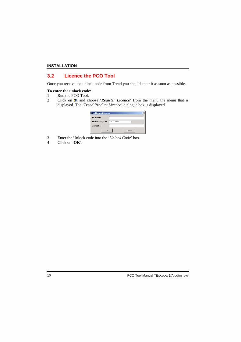
3.2 Licence the PCO Tool
Once you receive the unlock code from Trend you should enter it as soon as possible.
To enter the unlock code:1 Run the PCO Tool.2 Click on , and choose ‘Register Licence’ from the menu the menu that is
displayed. The ‘Trend Product Licence’ dialogue box is displayed.
3 Enter the Unlock code into the ‘Unlock Code’ box.4 Click on ‘OK’.
THE PCO TOOL WINDOW
PCO Tool Manual Texxxxxx Issue 1/A dd/mm/yy 11
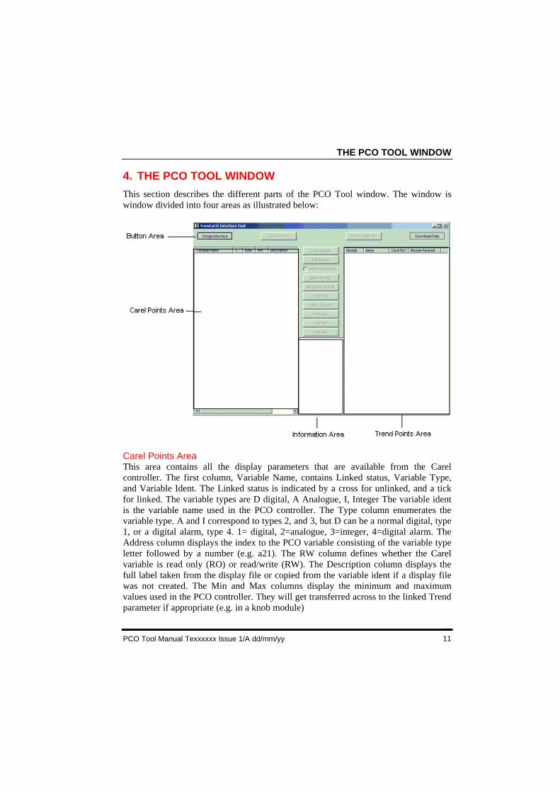
4. THE PCO TOOL WINDOW
This section describes the different parts of the PCO Tool window. The window iswindow divided into four areas as illustrated below:
Carel Points AreaThis area contains all the display parameters that are available from the Carelcontroller. The first column, Variable Name, contains Linked status, Variable Type,and Variable Ident. The Linked status is indicated by a cross for unlinked, and a tickfor linked. The variable types are D digital, A Analogue, I, Integer The variable identis the variable name used in the PCO controller. The Type column enumerates thevariable type. A and I correspond to types 2, and 3, but D can be a normal digital, type1, or a digital alarm, type 4. 1= digital, 2=analogue, 3=integer, 4=digital alarm. TheAddress column displays the index to the PCO variable consisting of the variable typeletter followed by a number (e.g. a21). The RW column defines whether the Carelvariable is read only (RO) or read/write (RW). The Description column displays thefull label taken from the display file or copied from the variable ident if a display filewas not created. The Min and Max columns display the minimum and maximumvalues used in the PCO controller. They will get transferred across to the linked Trendparameter if appropriate (e.g. in a knob module)
THE PCO TOOL WINDOW
PCO Tool Manual TExxxxxx 1/A dd/mm/yy12
4. THE PCO TOOL WINDOW (Continued)
Trend Points AreaThis area contains a list of all the Trend modules that have been added to the interface.
Button AreaThis area contains all the buttons which enable different tasks to be performed.
Information AreaThis area contains details about the number of modules that have been added, howmany are left, and the memory usage.

IQPCO MODULES
PCO Tool Manual Texxxxxx Issue 1/A dd/mm/yy 13
5 ENGINEER A PCO INTERFACE
For the interface to work the Carel parameters that are to be accessed from the Trendsystem must be linked to a parameter within a Trend module, and for the interface tobe configured to communicate with the Trend network
To Engineer a IQPCO interface card:1 Obtain the necessary files.2 Create the .CDE file.3 Load the .CDE file into the PCO Tool.4 Set up the Address module.5 Set up the Time module.6 Link the Carel parameters to Trend parameters.7 Add any required Plot Modules.8 Add any required IC Comms Modules.9 Add a User Module if required.10 Set up the Display and Directory Modules.11 Create the Data File for downloading.12 Download the file.
5.1 Obtain the Necessary Files
The engineering of the IQPCO interface card requires the .TRR, and .BLK filescreated by Carel Easy Tools during the creation of the strategy. Therefore it isnecessary to obtain them from the strategy designer.
5.2 Create the .CDE file
The PCO Tool requires a .CDE file to enable engineering of the PCO. This files iscreated by processing the .TRR, and .BLK files created by Carel Easy Tools usingCarel CDE Maker.
ENGINEER A PCO INTERFACE
PCO Tool Manual TExxxxxx 1/A dd/mm/yy14
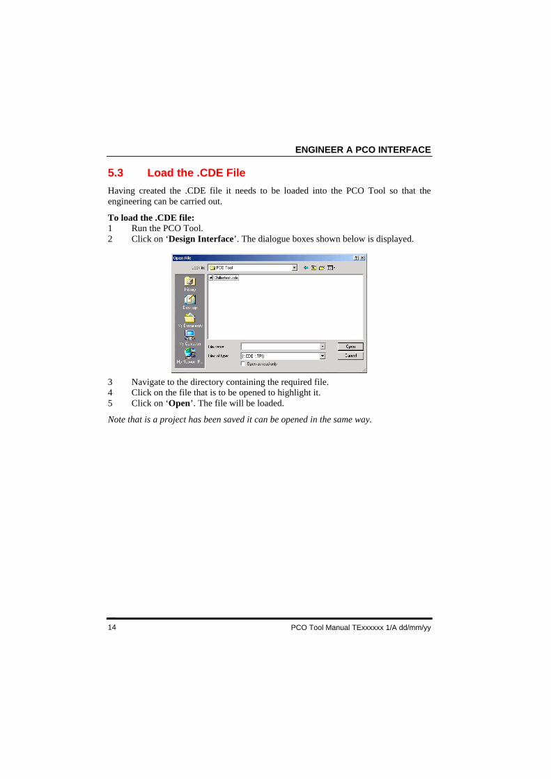
5.3 Load the .CDE File
Having created the .CDE file it needs to be loaded into the PCO Tool so that theengineering can be carried out.
To load the .CDE file:1 Run the PCO Tool.2 Click on ‘Design Interface’. The dialogue boxes shown below is displayed.
3 Navigate to the directory containing the required file.4 Click on the file that is to be opened to highlight it.5 Click on ‘Open’. The file will be loaded.
Note that is a project has been saved it can be opened in the same way.
IQPCO MODULES
PCO Tool Manual Texxxxxx Issue 1/A dd/mm/yy 15
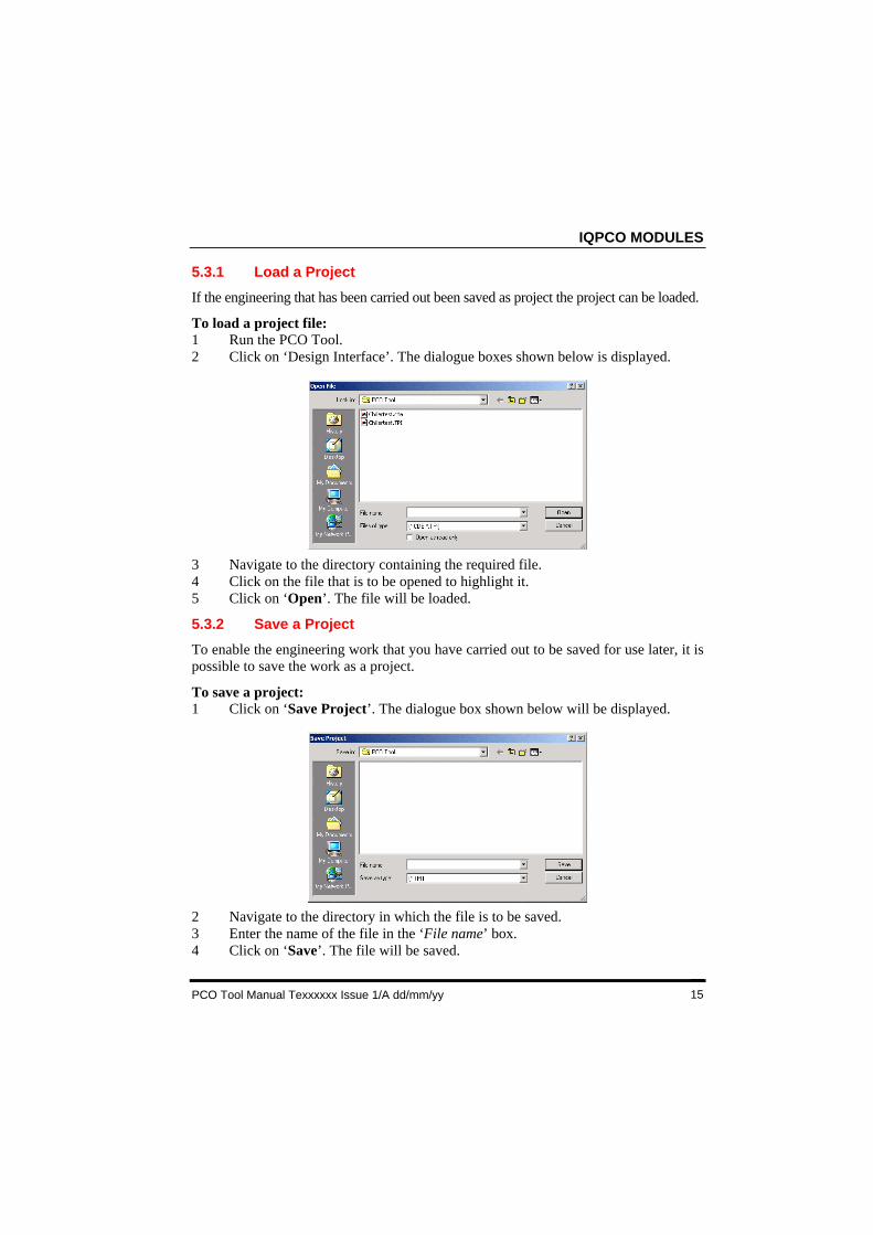
5.3.1 Load a Project
If the engineering that has been carried out been saved as project the project can be loaded.
To load a project file:1 Run the PCO Tool.2 Click on ‘Design Interface’. The dialogue boxes shown below is displayed.
3 Navigate to the directory containing the required file.4 Click on the file that is to be opened to highlight it.5 Click on ‘Open’. The file will be loaded.
5.3.2 Save a Project
To enable the engineering work that you have carried out to be saved for use later, it ispossible to save the work as a project.
To save a project:1 Click on ‘Save Project’. The dialogue box shown below will be displayed.
2 Navigate to the directory in which the file is to be saved.3 Enter the name of the file in the ‘File name’ box.4 Click on ‘Save’. The file will be saved.
ENGINEER A PCO INTERFACE
PCO Tool Manual TExxxxxx 1/A dd/mm/yy16
5.3.3 Run the PCO Tool
The PCO Tool is run in the same way as any other Windows application.
To run the PCO Tool:1 Run Windows.2 Choose ‘start>programs>trend control systems> PCO Tool>PCO Tool’.
5.3.4 Close the PCO Tool
The PCO Tool is closed in the same way as other windows applications
To close the PCO Tool:1 Click on in the PCO Tool window.
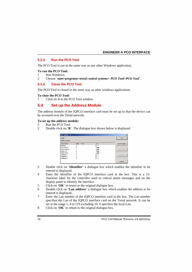
5.4 Set up the Address Module
The address module of the IQPCO interface card must be set up so that the device canbe accessed over the Trend network.
To set up the address module:1 Run the PCO Tool.2 Double click on ‘R’. The dialogue box shown below is displayed.
3 Double click on ‘Identifier’ a dialogue box which enables the identifier to beentered is displayed.
4 Enter the identifier of the IQPCO interface card in the box. This is a 15-character label for the controller used in critical alarm messages and on thedisplay panel to identify the interface.
5 Click on ‘OK’ to return to the original dialogue box.6 Double click on ‘Lan address’ a dialogue box which enables the address to be
entered is displayed.7 Enter the Lan number of the IQPCO interface card in the box. The Lan number
specifies the Lan of the IQPCO interface card on the Trend network. It can beset in the range 1, 4 to 119 excluding 10. 0 specifies the local Lan.
8 Click on ‘OK’ to return to the original dialogue box.
IQPCO MODULES
PCO Tool Manual Texxxxxx Issue 1/A dd/mm/yy 17
5.4 Set up the Address Module (Continued)
9 Double click on ‘Node address’ a dialogue box which enables the address to beentered is displayed.
10 Enter the network address of the IQPCO interface card in the box. The networkaddress specifies the address of the interface on the Trend network. It can be setin the range 1, 4 to 119 excluding 10. This must be the same as that set on theinterfaces address switch.
11 Click on ‘OK’ to return to the original dialogue box.12 Double click on ‘Alarm Lan’ a dialogue box which enables the alarm Lan to be
entered is displayed.13 Enter the alarm Lan of the IQPCO interface card in the box. The alarm Lan
specifies the Lan of the device to which alarms are sent. It can be set in therange 1, 4 to 119 excluding 10. 0 specifies the local Lan.
14 Click on ‘OK’ to return to the original dialogue box.15 Double click on ‘Alarm node’ a dialogue box which enables the Lan node to be
entered is displayed.16 Enter the alarm node of the IQPCO interface card in the box. The alarm node
specifies the device to which alarms are sent. It can be set in the range 1, 4 to119 excluding 10.
17 Click on ‘OK’ to return to the original dialogue box.18 Double click on ‘Attribute F’ a dialogue box which enables the F attribute to be
entered is displayed.19 Enter the F attribute of the IQPCO interface card in the box.20 Click on ‘OK’ to return to the original dialogue box.21 Double click on ‘Attribute G’ a dialogue box which enables the G attribute to
be entered is displayed.22 Enter the G attribute of the IQPCO interface card in the box.23 Click on ‘OK’ to return to the original dialogue box.24 Double click on ‘Attribute H’ a dialogue box which enables the H attribute to
be entered is displayed.25 Enter the H attribute of the IQPCO interface card in the box.26 Click on ‘OK’ to return to the original dialogue box.27 Click on ‘OK’.
ENGINEER A PCO INTERFACE
PCO Tool Manual TExxxxxx 1/A dd/mm/yy18
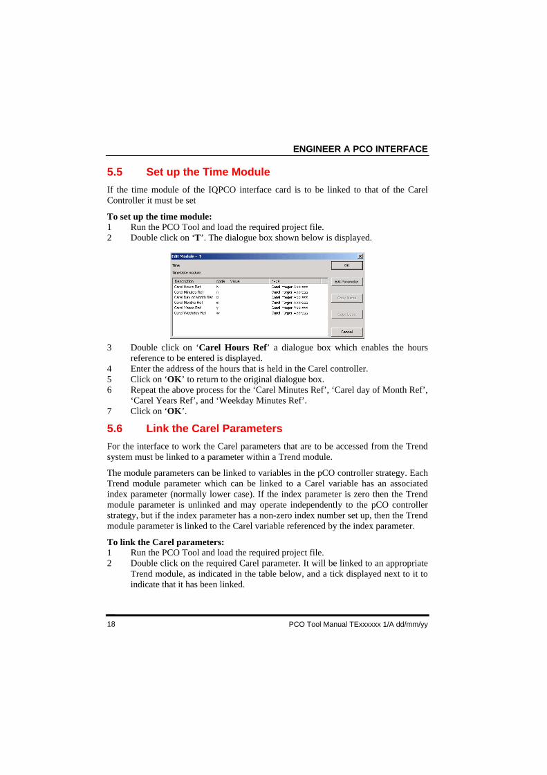
5.5 Set up the Time Module
If the time module of the IQPCO interface card is to be linked to that of the CarelController it must be set
To set up the time module:1 Run the PCO Tool and load the required project file.2 Double click on ‘T’. The dialogue box shown below is displayed.
3 Double click on ‘Carel Hours Ref’ a dialogue box which enables the hoursreference to be entered is displayed.
4 Enter the address of the hours that is held in the Carel controller.5 Click on ‘OK’ to return to the original dialogue box.6 Repeat the above process for the ‘Carel Minutes Ref’, ‘Carel day of Month Ref’,
‘Carel Years Ref’, and ‘Weekday Minutes Ref’.7 Click on ‘OK’.
5.6 Link the Carel Parameters
For the interface to work the Carel parameters that are to be accessed from the Trendsystem must be linked to a parameter within a Trend module.
The module parameters can be linked to variables in the pCO controller strategy. EachTrend module parameter which can be linked to a Carel variable has an associatedindex parameter (normally lower case). If the index parameter is zero then the Trendmodule parameter is unlinked and may operate independently to the pCO controllerstrategy, but if the index parameter has a non-zero index number set up, then the Trendmodule parameter is linked to the Carel variable referenced by the index parameter.
To link the Carel parameters:1 Run the PCO Tool and load the required project file.2 Double click on the required Carel parameter. It will be linked to an appropriate
Trend module, as indicated in the table below, and a tick displayed next to it toindicate that it has been linked.
IQPCO MODULES
PCO Tool Manual Texxxxxx Issue 1/A dd/mm/yy 19
5.6 Link the Carel Parameters (Continued)
Carel Variable Trend VariableVariable type Type RWA 2 RO S (Sensor)A 2 RW K (Knob)I 3 RO S (Sensor)I 3 RW K (Knob)D 1 or 4 RO I (Digital Input)D 1 or 4 RW W (Switch)
The current number of modules used etc. are shown in the central column below thebuttons. This shows the number of sequence steps used and remaining, and thememory used and remaining. The total memory of ~ 8 kbyte (8400 bytes) is reduced asthe modules are created. Below this are the numbers of modules used of each type.
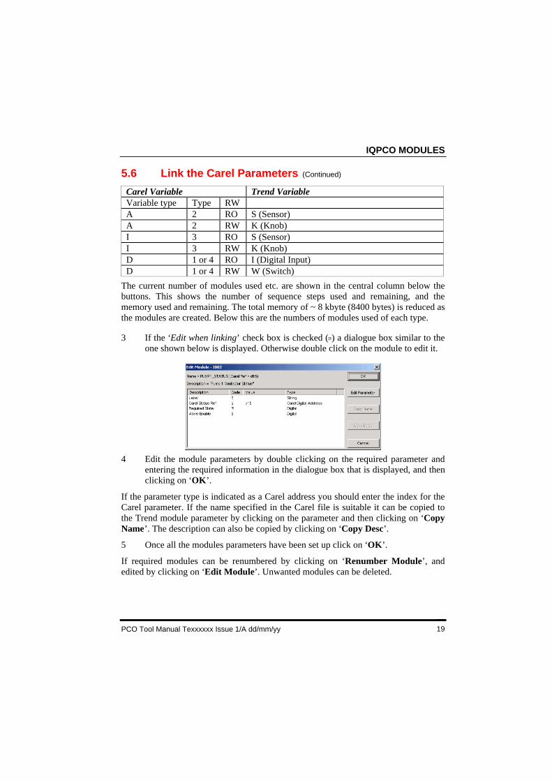
3 If the ‘Edit when linking’ check box is checked ( ) a dialogue box similar to theone shown below is displayed. Otherwise double click on the module to edit it.
4 Edit the module parameters by double clicking on the required parameter andentering the required information in the dialogue box that is displayed, and thenclicking on ‘OK’.
If the parameter type is indicated as a Carel address you should enter the index for theCarel parameter. If the name specified in the Carel file is suitable it can be copied tothe Trend module parameter by clicking on the parameter and then clicking on ‘CopyName’. The description can also be copied by clicking on ‘Copy Desc’.
5 Once all the modules parameters have been set up click on ‘OK’.
If required modules can be renumbered by clicking on ‘Renumber Module’, andedited by clicking on ‘Edit Module’. Unwanted modules can be deleted.

ENGINEER A PCO INTERFACE
PCO Tool Manual TExxxxxx 1/A dd/mm/yy20
5.6.1 Delete a Module
If a module is no longer required it can be deleted.
To delete a module:1 Run the PCO Tool and load the required project file.2 Click on the Trend module that is to be deleted so that it is highlighted.3 Click on ‘Delete Module’.
5.6.2 Edit a Module
If a module can be edited.
To edit a module:1 Run the PCO Tool and load the required project file.2 Click on the Trend module that is to be edited so that it is highlighted.3 Click on ‘Edit Module’ to display a dialogue box containing the modules
parameters4 Edit the module’s parameters as required5 Click on ‘OK’.
5.6.3 Renumber a Module
If a required a module’s number can be changed.
To renumber a module:1 Run the PCO Tool and load the required project file.2 Click on the Trend module that is to be renumbered so that it is highlighted.3 Click on ‘Renumber Module’. A dialogue box is displayed prompting for the
new module number.4 Enter the new module number in the box.5 Click on ‘OK’.
5.6.4 Enable/Disable Automatic Editing
Automatic edit cause the module edit dialogue box to be displayed when a module islinked. This feature can be turned on/off as required
To enable/disable automatic editing:1 Run the PCO Tool and load the required project file.2 Click on the Trend module that is to be renumbered so that it is highlighted.3 Check ( )/uncheck ( ) the ‘Edit when linking’ check box. Checked ( ) is
enabled.
IQPCO MODULES
PCO Tool Manual Texxxxxx Issue 1/A dd/mm/yy 21
5.7 Add Plot Modules
If the IQPCO interface card is to log values plot modules must be added. Up to 10 plotmodules can be added each of which will store a single compact log.
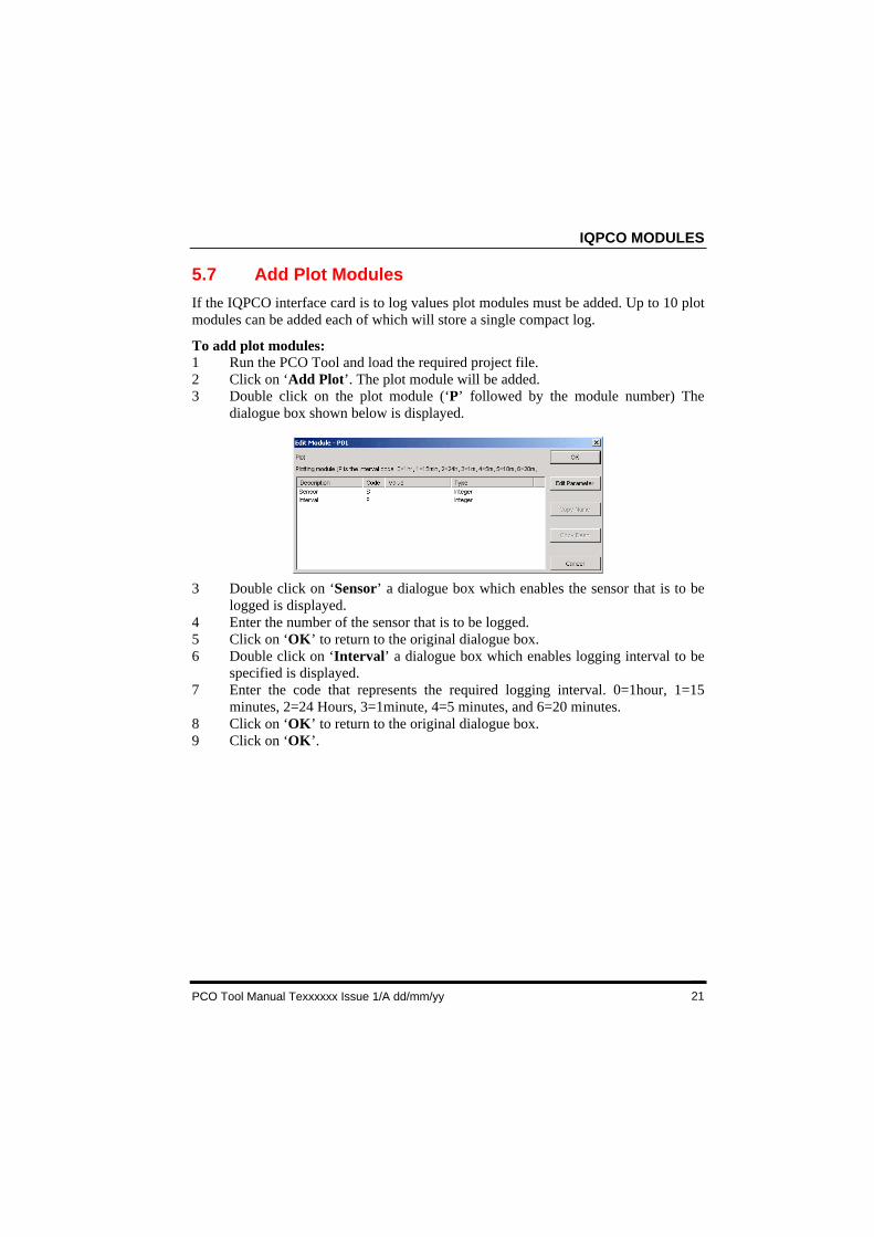
To add plot modules:1 Run the PCO Tool and load the required project file.2 Click on ‘Add Plot’. The plot module will be added.3 Double click on the plot module (‘P’ followed by the module number) The
dialogue box shown below is displayed.
3 Double click on ‘Sensor’ a dialogue box which enables the sensor that is to belogged is displayed.
4 Enter the number of the sensor that is to be logged.5 Click on ‘OK’ to return to the original dialogue box.6 Double click on ‘Interval’ a dialogue box which enables logging interval to be
specified is displayed.7 Enter the code that represents the required logging interval. 0=1hour, 1=15
minutes, 2=24 Hours, 3=1minute, 4=5 minutes, and 6=20 minutes.8 Click on ‘OK’ to return to the original dialogue box.9 Click on ‘OK’.
ENGINEER A PCO INTERFACE
PCO Tool Manual TExxxxxx 1/A dd/mm/yy22
5.8 Add IC Comms Modules
If the IQPCO interface card use IC comms messages to communicate with other Trenddevices IC comms modules must be added.
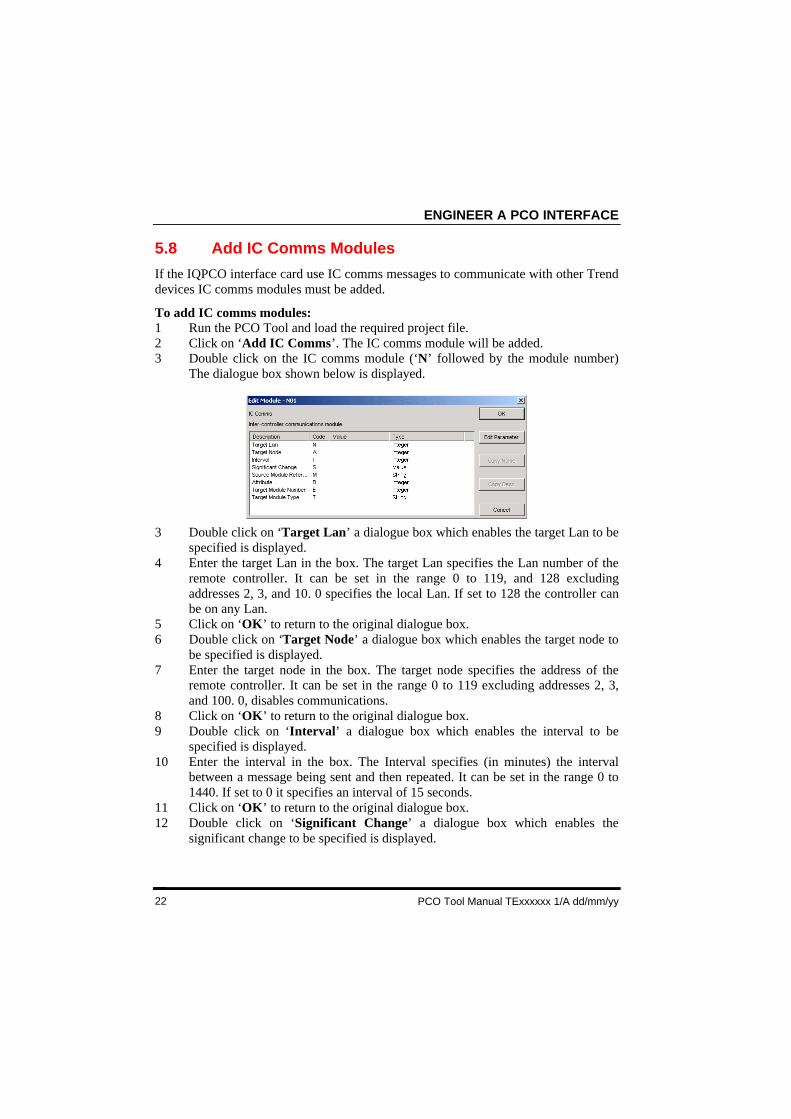
To add IC comms modules:1 Run the PCO Tool and load the required project file.2 Click on ‘Add IC Comms’. The IC comms module will be added.3 Double click on the IC comms module (‘N’ followed by the module number)
The dialogue box shown below is displayed.
3 Double click on ‘Target Lan’ a dialogue box which enables the target Lan to bespecified is displayed.
4 Enter the target Lan in the box. The target Lan specifies the Lan number of theremote controller. It can be set in the range 0 to 119, and 128 excludingaddresses 2, 3, and 10. 0 specifies the local Lan. If set to 128 the controller canbe on any Lan.
5 Click on ‘OK’ to return to the original dialogue box.6 Double click on ‘Target Node’ a dialogue box which enables the target node to
be specified is displayed.7 Enter the target node in the box. The target node specifies the address of the
remote controller. It can be set in the range 0 to 119 excluding addresses 2, 3,and 100. 0, disables communications.
8 Click on ‘OK’ to return to the original dialogue box.9 Double click on ‘Interval’ a dialogue box which enables the interval to be
specified is displayed.10 Enter the interval in the box. The Interval specifies (in minutes) the interval
between a message being sent and then repeated. It can be set in the range 0 to1440. If set to 0 it specifies an interval of 15 seconds.
11 Click on ‘OK’ to return to the original dialogue box.12 Double click on ‘Significant Change’ a dialogue box which enables the
significant change to be specified is displayed.
IQPCO MODULES
PCO Tool Manual Texxxxxx Issue 1/A dd/mm/yy 23
5.8 Add IC Comms Modules (Continued)
13 Enter the significant change in the box. The significant change specifies theamount the value of the source address is allowed to change before a message issent. It can be set in the range -3276 to +3276.
14 Click on ‘OK’ to return to the original dialogue box.15 Double click on ‘Source Module Reference’ a dialogue box which enables the
source module reference to be specified is displayed.16 Enter the source module reference in the box.17 Click on ‘OK’ to return to the original dialogue box.18 Double click on ‘Attribute’ a dialogue box which enables the attribute to be
specified is displayed.19 Enter the attribute in the box. The attribute specifies the particular attribute that
must match in all devices for them to respond to the message. It can be set in therange 0 to 7 where 0=comms disabled, 1=identifier, 2=F attribute, 3=G attribute,4=H attribute, 5=I attribute, 6=J attribute, and 7=K attribute.
20 Click on ‘OK’ to return to the original dialogue box.21 Double click on ‘Target Module Number’ a dialogue box which enables the
target module to be specified is displayed.22 Enter the target module number in the box.23 Click on ‘OK’ to return to the original dialogue box.24 Double click on ‘Target Module Type’ a dialogue box which enables the target
module type to be specified is displayed.25 Enter the target module type in the box.26 Click on ‘OK’ to return to the original dialogue box.27 Click on ‘OK’.
ENGINEER A PCO INTERFACE
PCO Tool Manual TExxxxxx 1/A dd/mm/yy24
5.9 Add a User Module
If the IQPCO interface card have PIN protection enabled a user module must beadded. The IQPCO interface card has a single user module that when set up willprevent any changes being made unless the correct PIN is used.
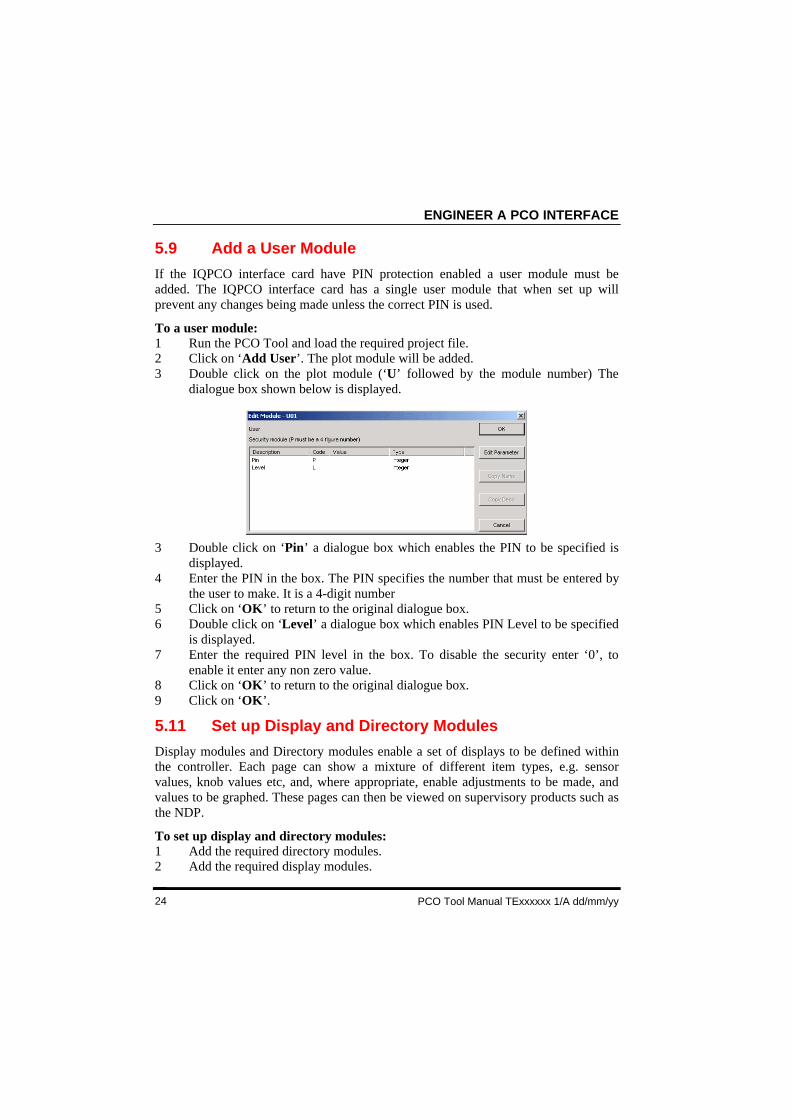
To a user module:1 Run the PCO Tool and load the required project file.2 Click on ‘Add User’. The plot module will be added.3 Double click on the plot module (‘U’ followed by the module number) The
dialogue box shown below is displayed.
3 Double click on ‘Pin’ a dialogue box which enables the PIN to be specified isdisplayed.
4 Enter the PIN in the box. The PIN specifies the number that must be entered bythe user to make. It is a 4-digit number
5 Click on ‘OK’ to return to the original dialogue box.6 Double click on ‘Level’ a dialogue box which enables PIN Level to be specified
is displayed.7 Enter the required PIN level in the box. To disable the security enter ‘0’, to
enable it enter any non zero value.8 Click on ‘OK’ to return to the original dialogue box.9 Click on ‘OK’.
5.11 Set up Display and Directory Modules
Display modules and Directory modules enable a set of displays to be defined withinthe controller. Each page can show a mixture of different item types, e.g. sensorvalues, knob values etc, and, where appropriate, enable adjustments to be made, andvalues to be graphed. These pages can then be viewed on supervisory products such asthe NDP.
To set up display and directory modules:1 Add the required directory modules.2 Add the required display modules.
IQPCO MODULES
PCO Tool Manual Texxxxxx Issue 1/A dd/mm/yy 25
5.11.1 Add Directory Module
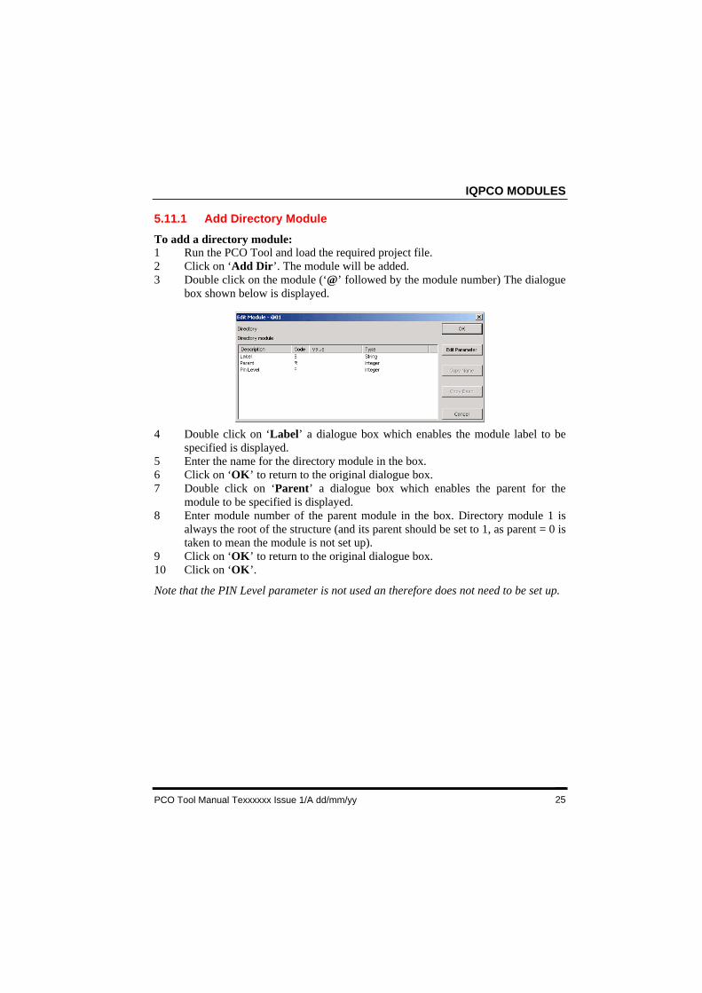
To add a directory module:1 Run the PCO Tool and load the required project file.2 Click on ‘Add Dir’. The module will be added.3 Double click on the module (‘@’ followed by the module number) The dialogue
box shown below is displayed.
4 Double click on ‘Label’ a dialogue box which enables the module label to bespecified is displayed.
5 Enter the name for the directory module in the box.6 Click on ‘OK’ to return to the original dialogue box.7 Double click on ‘Parent’ a dialogue box which enables the parent for the
module to be specified is displayed.8 Enter module number of the parent module in the box. Directory module 1 is
always the root of the structure (and its parent should be set to 1, as parent = 0 istaken to mean the module is not set up).
9 Click on ‘OK’ to return to the original dialogue box.10 Click on ‘OK’.
Note that the PIN Level parameter is not used an therefore does not need to be set up.
ENGINEER A PCO INTERFACE
PCO Tool Manual TExxxxxx 1/A dd/mm/yy26
5.11.1 Add Display Modulef
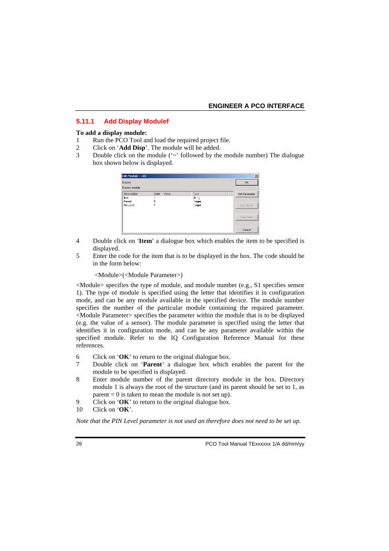
To add a display module:1 Run the PCO Tool and load the required project file.2 Click on ‘Add Disp’. The module will be added.3 Double click on the module (‘~’ followed by the module number) The dialogue
box shown below is displayed.
4 Double click on ‘Item’ a dialogue box which enables the item to be specified isdisplayed.
5 Enter the code for the item that is to be displayed in the box. The code should bein the form below:
<Module>(<Module Parameter>)
<Module> specifies the type of module, and module number (e.g., S1 specifies sensor1). The type of module is specified using the letter that identifies it in configurationmode, and can be any module available in the specified device. The module numberspecifies the number of the particular module containing the required parameter.<Module Parameter> specifies the parameter within the module that is to be displayed(e.g. the value of a sensor). The module parameter is specified using the letter thatidentifies it in configuration mode, and can be any parameter available within thespecified module. Refer to the IQ Configuration Reference Manual for thesereferences.
6 Click on ‘OK’ to return to the original dialogue box.7 Double click on ‘Parent’ a dialogue box which enables the parent for the
module to be specified is displayed.8 Enter module number of the parent directory module in the box. Directory
module 1 is always the root of the structure (and its parent should be set to 1, asparent = 0 is taken to mean the module is not set up).
9 Click on ‘OK’ to return to the original dialogue box.10 Click on ‘OK’.
Note that the PIN Level parameter is not used an therefore does not need to be set up.
IQPCO MODULES
PCO Tool Manual Texxxxxx Issue 1/A dd/mm/yy 27
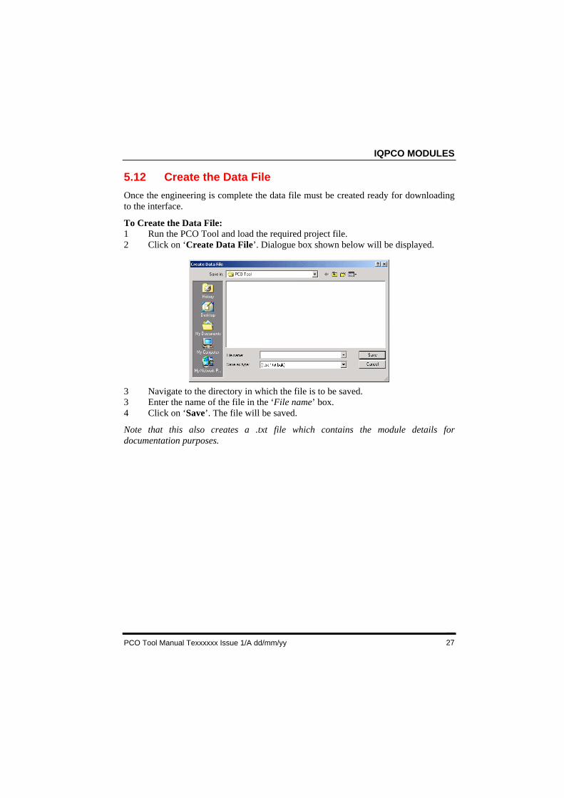
5.12 Create the Data File
Once the engineering is complete the data file must be created ready for downloadingto the interface.
To Create the Data File:1 Run the PCO Tool and load the required project file.2 Click on ‘Create Data File’. Dialogue box shown below will be displayed.
3 Navigate to the directory in which the file is to be saved.3 Enter the name of the file in the ‘File name’ box.4 Click on ‘Save’. The file will be saved.
Note that this also creates a .txt file which contains the module details fordocumentation purposes.
ENGINEER A PCO INTERFACE
PCO Tool Manual TExxxxxx 1/A dd/mm/yy28
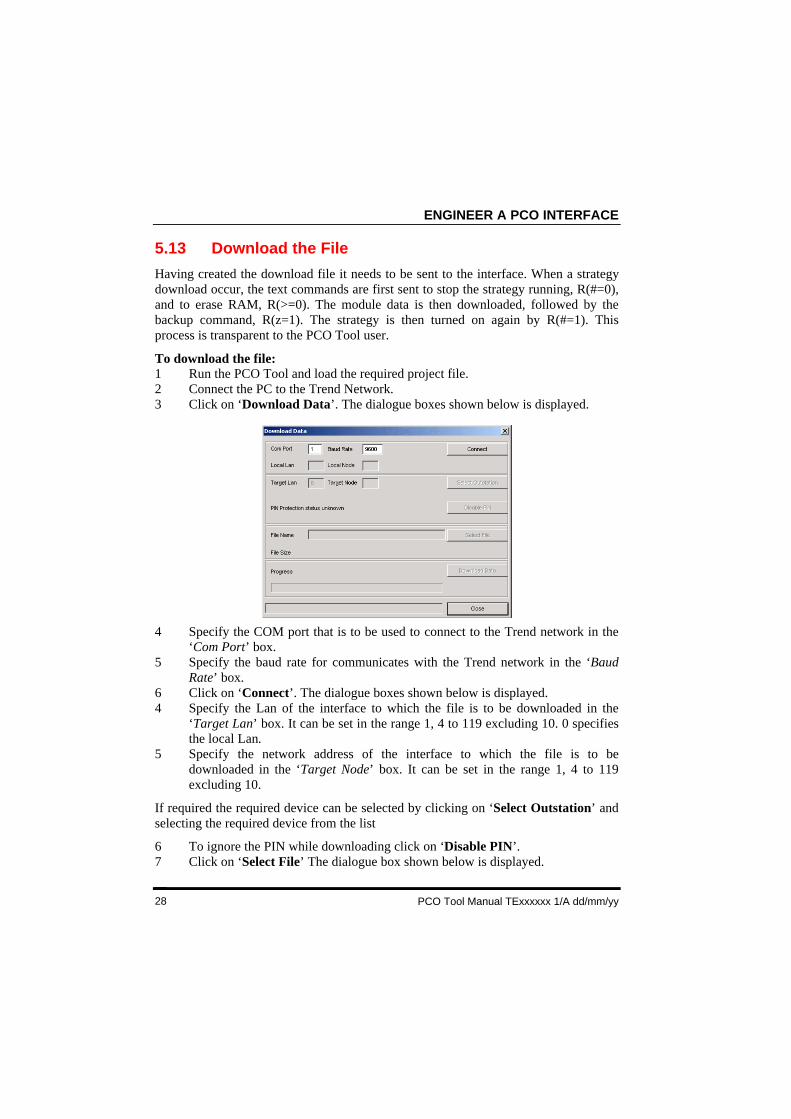
5.13 Download the File
Having created the download file it needs to be sent to the interface. When a strategydownload occur, the text commands are first sent to stop the strategy running, R(#=0),and to erase RAM, R(>=0). The module data is then downloaded, followed by thebackup command, R(z=1). The strategy is then turned on again by R(#=1). Thisprocess is transparent to the PCO Tool user.
To download the file:1 Run the PCO Tool and load the required project file.2 Connect the PC to the Trend Network.3 Click on ‘Download Data’. The dialogue boxes shown below is displayed.
4 Specify the COM port that is to be used to connect to the Trend network in the‘Com Port’ box.
5 Specify the baud rate for communicates with the Trend network in the ‘BaudRate’ box.
6 Click on ‘Connect’. The dialogue boxes shown below is displayed.4 Specify the Lan of the interface to which the file is to be downloaded in the
‘Target Lan’ box. It can be set in the range 1, 4 to 119 excluding 10. 0 specifiesthe local Lan.
5 Specify the network address of the interface to which the file is to bedownloaded in the ‘Target Node’ box. It can be set in the range 1, 4 to 119excluding 10.
If required the required device can be selected by clicking on ‘Select Outstation’ andselecting the required device from the list
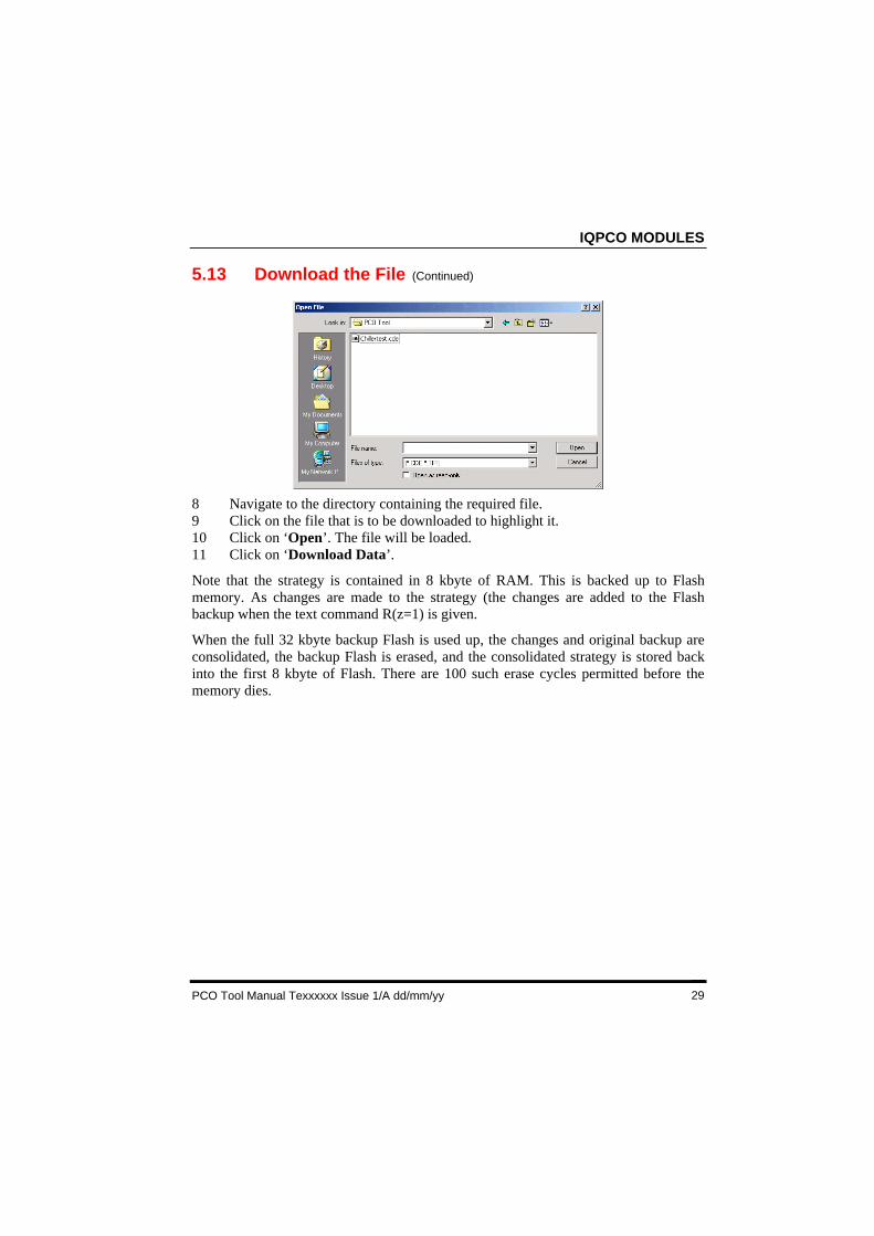
6 To ignore the PIN while downloading click on ‘Disable PIN’.7 Click on ‘Select File’ The dialogue box shown below is displayed.
IQPCO MODULES
PCO Tool Manual Texxxxxx Issue 1/A dd/mm/yy 29
5.13 Download the File (Continued)
8 Navigate to the directory containing the required file.9 Click on the file that is to be downloaded to highlight it.10 Click on ‘Open’. The file will be loaded.11 Click on ‘Download Data’.
Note that the strategy is contained in 8 kbyte of RAM. This is backed up to Flashmemory. As changes are made to the strategy (the changes are added to the Flashbackup when the text command R(z=1) is given.
When the full 32 kbyte backup Flash is used up, the changes and original backup areconsolidated, the backup Flash is erased, and the consolidated strategy is stored backinto the first 8 kbyte of Flash. There are 100 such erase cycles permitted before thememory dies.
ENGINEER A PCO INTERFACE
PCO Tool Manual TExxxxxx 1/A dd/mm/yy30
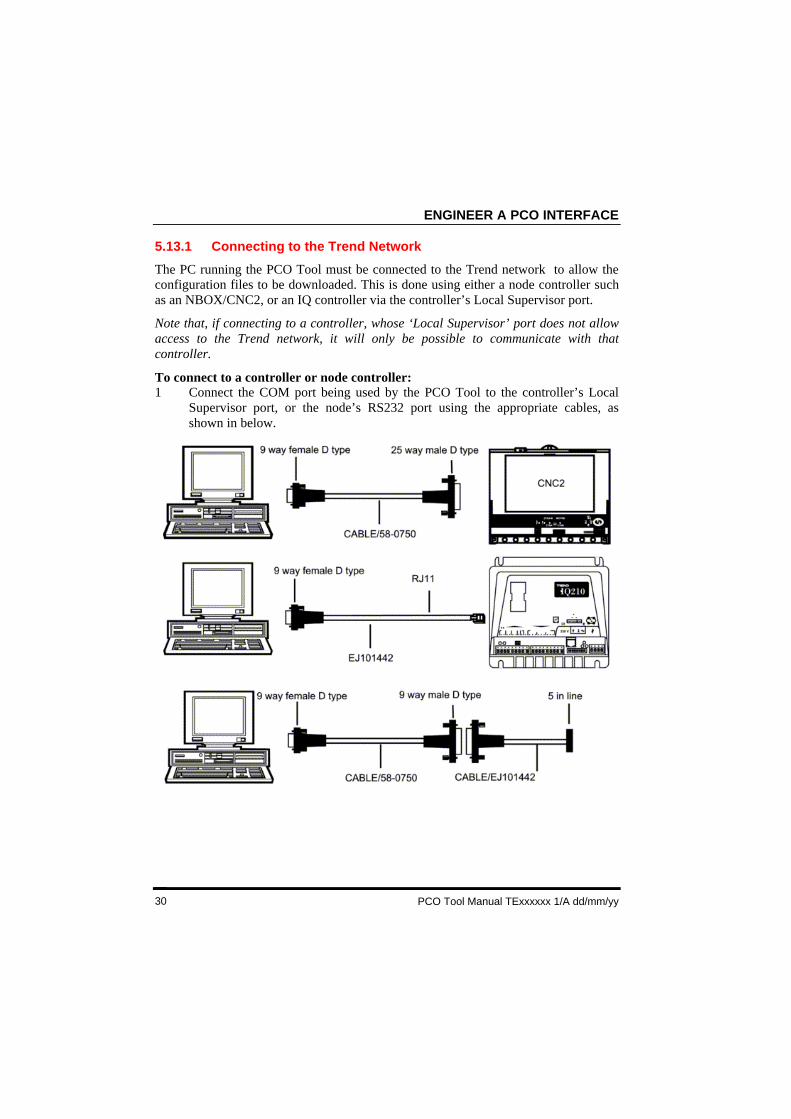
5.13.1 Connecting to the Trend Network
The PC running the PCO Tool must be connected to the Trend network to allow theconfiguration files to be downloaded. This is done using either a node controller suchas an NBOX/CNC2, or an IQ controller via the controller’s Local Supervisor port.
Note that, if connecting to a controller, whose ‘Local Supervisor’ port does not allowaccess to the Trend network, it will only be possible to communicate with thatcontroller.
To connect to a controller or node controller:1 Connect the COM port being used by the PCO Tool to the controller’s Local
Supervisor port, or the node’s RS232 port using the appropriate cables, asshown in below.

IQPCO MODULES
PCO Tool Manual Texxxxxx Issue 1/A dd/mm/yy 31
6 IQPCO MODULES
This section describes in detail all of the configuration parameters for each IQPCOmodule.
Address ModuleDigital Input Module:Directory ModuleDisplay ModuleInter Interface Communications ModuleKnob ModulePlot ModuleSensor ModuleSwitch ModuleTime ModuleUser Module
The IQPCO interface contains number of modules , they are of two types, those with afixed number of instances, and those which have a flexible number of instances.
The maximum number of flexible modules that can be created is limited by theavailable memory (the PCO Tool gives an indication of memory left), except forsensor logs (10 maximum), and User module (1 maximum).
The following table lists the different types of configuration modules and the numberof each type available in the IQPCO.
Module Type NumberAddress 1Digital Input FlexibleDirectory FlexibleDisplay FlexibleIC Comms FlexibleKnob FlexiblePlots Flexible (max 10)Sensor FlexibleSwitch FlexibleTime 1User 1 (does not need to be added)
IQPCO MODULES
PCO Tool Manual TExxxxxx 1/A dd/mm/yy32
6.1 Text Communications Parameters
The IQPCO modules have similar characteristics to the IQL interface modules asdescribed in the Trend LonWorks Products Engineering Guide, TE200292 (these arebased on the IQ modules described in the IQ Configuration Manual 90-1533).
The following parameters may be accessed via terse text communications. Please notethat any changes to the strategy parameters should be followed by a text comms resetcommand, R(z=1), after all the changes are made, to commit the changes to flashmemory and render them non-volatile to power interruptions - Use with caution topreserve memory life.
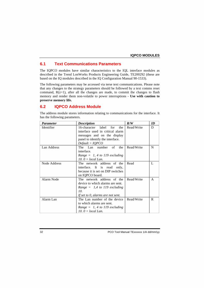
6.2 IQPCO Address Module
The address module stores information relating to communications for the interface. Ithas the following parameters.
Parameter Description R/W IDIdentifier 16-character label for the
interface used in critical alarmmessages and on the displaypanel to identify the interface.Default = IQPCO
Read/Write D
Lan Address The Lan number of theinterface.Range = 1, 4 to 119 excluding10. 0 = local Lan.
Read/Write N
Node Address The network address of theinterface. It is read only,because it is set on DIP switcheson IQPCO board.
Read L
Alarm Node The network address of thedevice to which alarms are sent.Range = 1,4 to 119 excluding10.If set to 0, alarms are not sent.
Read/Write A
Alarm Lan The Lan number of the deviceto which alarms are sent.Range = 1, 4 to 119 excluding10. 0 = local Lan.
Read/Write R
IQPCO MODULES
PCO Tool Manual Texxxxxx Issue 1/A dd/mm/yy 33
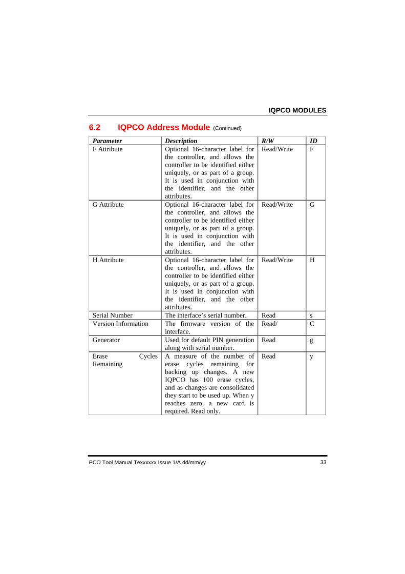
6.2 IQPCO Address Module (Continued)
Parameter Description R/W IDF Attribute Optional 16-character label for
the controller, and allows thecontroller to be identified eitheruniquely, or as part of a group.It is used in conjunction withthe identifier, and the otherattributes.
Read/Write F
G Attribute Optional 16-character label forthe controller, and allows thecontroller to be identified eitheruniquely, or as part of a group.It is used in conjunction withthe identifier, and the otherattributes.
Read/Write G
H Attribute Optional 16-character label forthe controller, and allows thecontroller to be identified eitheruniquely, or as part of a group.It is used in conjunction withthe identifier, and the otherattributes.
Read/Write H
Serial Number The interface’s serial number. Read sVersion Information The firmware version of the
interface.Read/ C
Generator Used for default PIN generationalong with serial number.
Read g
Erase CyclesRemaining
A measure of the number oferase cycles remaining forbacking up changes. A newIQPCO has 100 erase cycles,and as changes are consolidatedthey start to be used up. When yreaches zero, a new card isrequired. Read only.
Read y
IQPCO MODULES
PCO Tool Manual TExxxxxx 1/A dd/mm/yy34
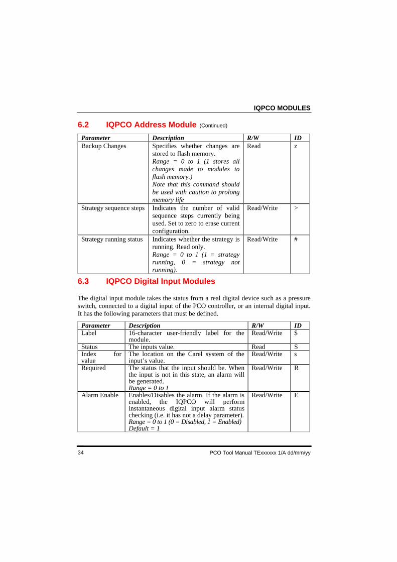
6.2 IQPCO Address Module (Continued)
Parameter Description R/W IDBackup Changes Specifies whether changes are
stored to flash memory.Range = 0 to 1 (1 stores allchanges made to modules toflash memory.)Note that this command shouldbe used with caution to prolongmemory life
Read z
Strategy sequence steps Indicates the number of validsequence steps currently beingused. Set to zero to erase currentconfiguration.
Read/Write >
Strategy running status Indicates whether the strategy isrunning. Read only.Range = 0 to 1 (1 = strategyrunning, 0 = strategy notrunning).
Read/Write #
6.3 IQPCO Digital Input Modules
The digital input module takes the status from a real digital device such as a pressureswitch, connected to a digital input of the PCO controller, or an internal digital input.It has the following parameters that must be defined.
Parameter Description R/W IDLabel 16-character user-friendly label for the
module.Read/Write $
Status The inputs value. Read SIndex forvalue
The location on the Carel system of theinput’s value.
Read/Write s
Required The status that the input should be. Whenthe input is not in this state, an alarm willbe generated.Range = 0 to 1
Read/Write R
Alarm Enable Enables/Disables the alarm. If the alarm isenabled, the IQPCO will performinstantaneous digital input alarm statuschecking (i.e. it has not a delay parameter).Range = 0 to 1 (0 = Disabled, 1 = Enabled)Default = 1
Read/Write E
IQPCO MODULES
PCO Tool Manual Texxxxxx Issue 1/A dd/mm/yy 35
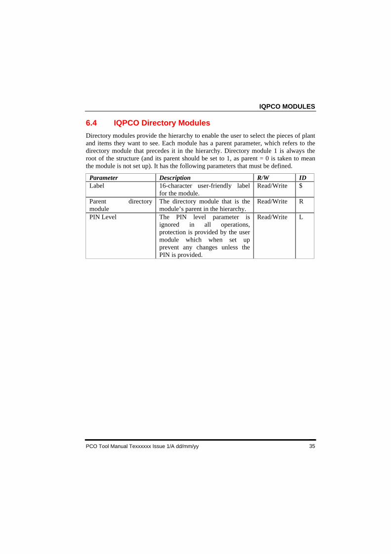
6.4 IQPCO Directory Modules
Directory modules provide the hierarchy to enable the user to select the pieces of plantand items they want to see. Each module has a parent parameter, which refers to thedirectory module that precedes it in the hierarchy. Directory module 1 is always theroot of the structure (and its parent should be set to 1, as parent = 0 is taken to meanthe module is not set up). It has the following parameters that must be defined.
Parameter Description R/W IDLabel 16-character user-friendly label
for the module.Read/Write $
Parent directorymodule
The directory module that is themodule’s parent in the hierarchy.
Read/Write R
PIN Level The PIN level parameter isignored in all operations,protection is provided by the usermodule which when set upprevent any changes unless thePIN is provided.
Read/Write L
IQPCO MODULES
PCO Tool Manual TExxxxxx 1/A dd/mm/yy36
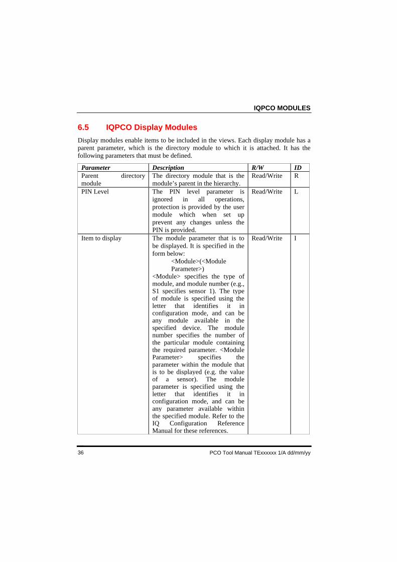
6.5 IQPCO Display Modules
Display modules enable items to be included in the views. Each display module has aparent parameter, which is the directory module to which it is attached. It has thefollowing parameters that must be defined.
Parameter Description R/W IDParent directorymodule
The directory module that is themodule’s parent in the hierarchy.
Read/Write R
PIN Level The PIN level parameter isignored in all operations,protection is provided by the usermodule which when set upprevent any changes unless thePIN is provided.
Read/Write L
Item to display The module parameter that is tobe displayed. It is specified in theform below:
<Module>(<ModuleParameter>)
<Module> specifies the type ofmodule, and module number (e.g.,S1 specifies sensor 1). The typeof module is specified using theletter that identifies it inconfiguration mode, and can beany module available in thespecified device. The modulenumber specifies the number ofthe particular module containingthe required parameter. <ModuleParameter> specifies theparameter within the module thatis to be displayed (e.g. the valueof a sensor). The moduleparameter is specified using theletter that identifies it inconfiguration mode, and can beany parameter available withinthe specified module. Refer to theIQ Configuration ReferenceManual for these references.
Read/Write I
IQPCO MODULES
PCO Tool Manual Texxxxxx Issue 1/A dd/mm/yy 37
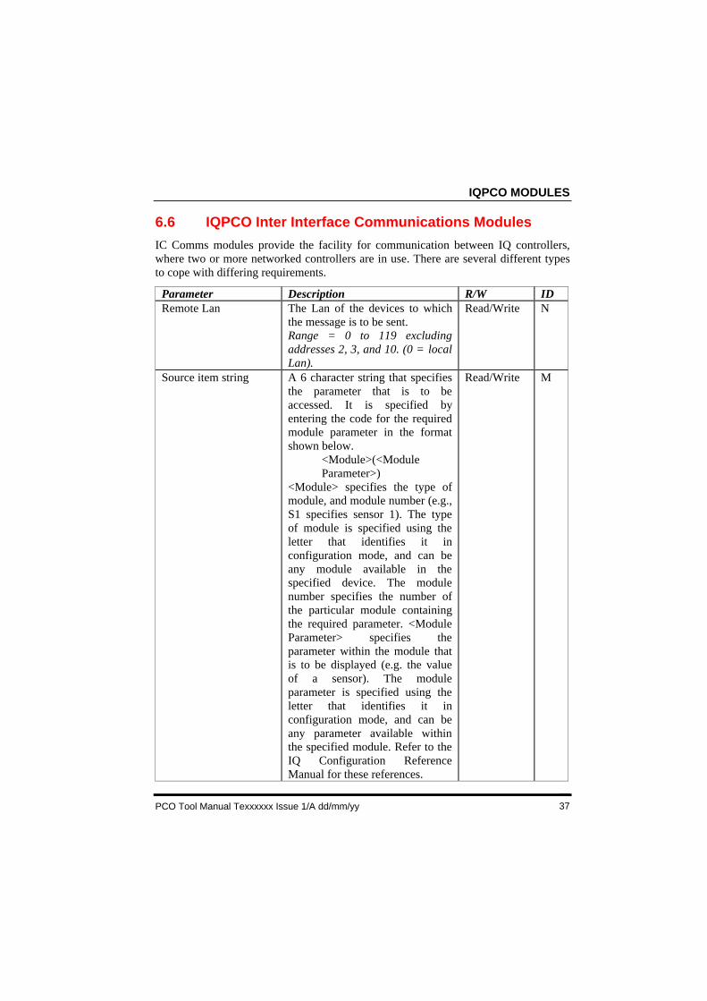
6.6 IQPCO Inter Interface Communications Modules
IC Comms modules provide the facility for communication between IQ controllers,where two or more networked controllers are in use. There are several different typesto cope with differing requirements.
Parameter Description R/W IDRemote Lan The Lan of the devices to which
the message is to be sent.Range = 0 to 119 excludingaddresses 2, 3, and 10. (0 = localLan).
Read/Write N
Source item string A 6 character string that specifiesthe parameter that is to beaccessed. It is specified byentering the code for the requiredmodule parameter in the formatshown below.
<Module>(<ModuleParameter>)
<Module> specifies the type ofmodule, and module number (e.g.,S1 specifies sensor 1). The typeof module is specified using theletter that identifies it inconfiguration mode, and can beany module available in thespecified device. The modulenumber specifies the number ofthe particular module containingthe required parameter. <ModuleParameter> specifies theparameter within the module thatis to be displayed (e.g. the valueof a sensor). The moduleparameter is specified using theletter that identifies it inconfiguration mode, and can beany parameter available withinthe specified module. Refer to theIQ Configuration ReferenceManual for these references.
Read/Write M
IQPCO MODULES
PCO Tool Manual TExxxxxx 1/A dd/mm/yy38
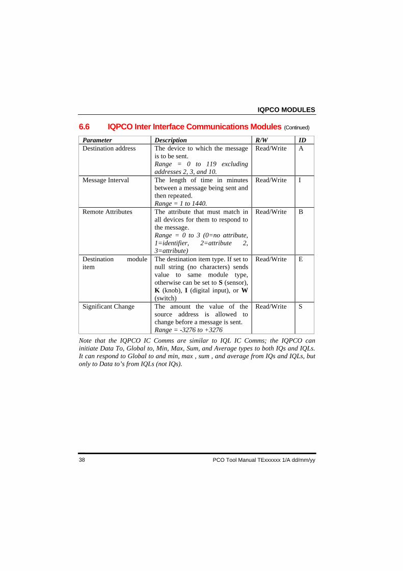
6.6 IQPCO Inter Interface Communications Modules (Continued)
Parameter Description R/W IDDestination address The device to which the message
is to be sent.Range = 0 to 119 excludingaddresses 2, 3, and 10.
Read/Write A
Message Interval The length of time in minutesbetween a message being sent andthen repeated.Range = 1 to 1440.
Read/Write I
Remote Attributes The attribute that must match inall devices for them to respond tothe message.Range = 0 to 3 (0=no attribute,1=identifier, 2=attribute 2,3=attribute)
Read/Write B
Destination moduleitem
The destination item type. If set tonull string (no characters) sendsvalue to same module type,otherwise can be set to S (sensor),K (knob), I (digital input), or W(switch)
Read/Write E
Significant Change The amount the value of thesource address is allowed tochange before a message is sent.Range = -3276 to +3276
Read/Write S
Note that the IQPCO IC Comms are similar to IQL IC Comms; the IQPCO caninitiate Data To, Global to, Min, Max, Sum, and Average types to both IQs and IQLs.It can respond to Global to and min, max , sum , and average from IQs and IQLs, butonly to Data to’s from IQLs (not IQs).
IQPCO MODULES
PCO Tool Manual Texxxxxx Issue 1/A dd/mm/yy 39
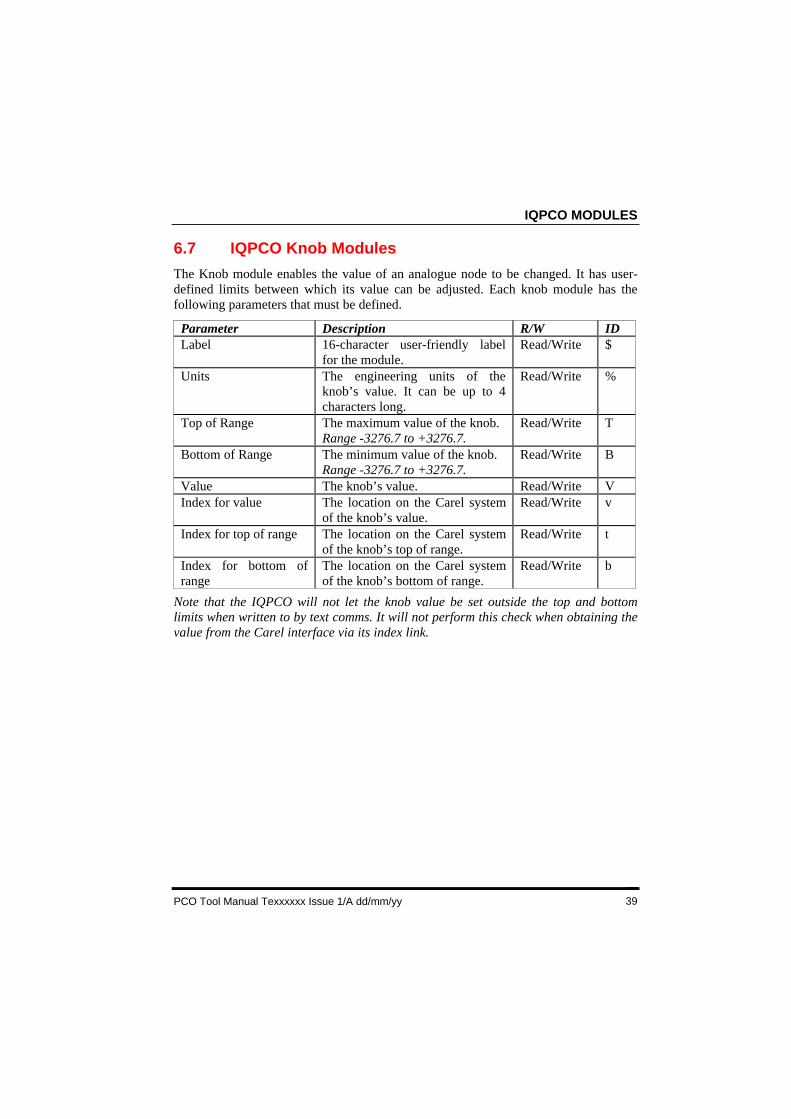
6.7 IQPCO Knob Modules
The Knob module enables the value of an analogue node to be changed. It has user-defined limits between which its value can be adjusted. Each knob module has thefollowing parameters that must be defined.
Parameter Description R/W IDLabel 16-character user-friendly label
for the module.Read/Write $
Units The engineering units of theknob’s value. It can be up to 4characters long.
Read/Write %
Top of Range The maximum value of the knob.Range -3276.7 to +3276.7.
Read/Write T
Bottom of Range The minimum value of the knob.Range -3276.7 to +3276.7.
Read/Write B
Value The knob’s value. Read/Write VIndex for value The location on the Carel system
of the knob’s value.Read/Write v
Index for top of range The location on the Carel systemof the knob’s top of range.
Read/Write t
Index for bottom ofrange
The location on the Carel systemof the knob’s bottom of range.
Read/Write b
Note that the IQPCO will not let the knob value be set outside the top and bottomlimits when written to by text comms. It will not perform this check when obtaining thevalue from the Carel interface via its index link.
IQPCO MODULES
PCO Tool Manual TExxxxxx 1/A dd/mm/yy40
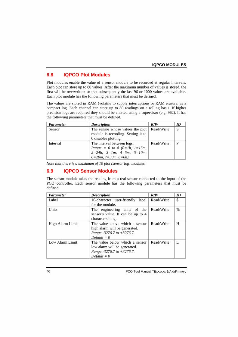
6.8 IQPCO Plot Modules
Plot modules enable the value of a sensor module to be recorded at regular intervals.Each plot can store up to 80 values. After the maximum number of values is stored, thefirst will be overwritten so that subsequently the last 96 or 1000 values are available.Each plot module has the following parameters that must be defined.
The values are stored in RAM (volatile to supply interruptions or RAM erasure, as acompact log. Each channel can store up to 80 readings on a rolling basis. If higherprecision logs are required they should be charted using a supervisor (e.g. 962). It hasthe following parameters that must be defined.
Parameter Description R/W IDSensor The sensor whose values the plot
module is recording. Setting it to0 disables plotting.
Read/Write S
Interval The interval between logs.Range = 0 to 8 (0=1h, 1=15m,2=24h, 3=1m, 4=5m, 5=10m,6=20m, 7=30m, 8=6h).
Read/Write P
Note that there is a maximum of 10 plot (sensor log) modules.
6.9 IQPCO Sensor Modules
The sensor module takes the reading from a real sensor connected to the input of thePCO controller. Each sensor module has the following parameters that must bedefined.
Parameter Description R/W IDLabel 16-character user-friendly label
for the module.Read/Write $
Units The engineering units of thesensor's value. It can be up to 4characters long.
Read/Write %
High Alarm Limit The value above which a sensorhigh alarm will be generated.Range -3276.7 to +3276.7.Default = 0
Read/Write H
Low Alarm Limit The value below which a sensorlow alarm will be generated.Range -3276.7 to +3276.7.Default = 0
Read/Write L
IQPCO MODULES
PCO Tool Manual Texxxxxx Issue 1/A dd/mm/yy 41
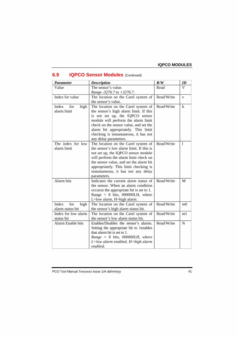
6.9 IQPCO Sensor Modules (Continued)
Parameter Description R/W IDValue The sensor’s value.
Range -3276.7 to +3276.7.Read V
Index for value The location on the Carel system ofthe sensor’s value.
Read/Write v
Index for highalarm limit
The location on the Carel system ofthe sensor’s high alarm limit. If thisis not set up, the IQPCO sensormodule will perform the alarm limitcheck on the sensor value, and set thealarm bit appropriately. This limitchecking is instantaneous, it has notany delay parameters.
Read/Write h
The index for lowalarm limit
The location on the Carel system ofthe sensor’s low alarm limit. If this isnot set up, the IQPCO sensor modulewill perform the alarm limit check onthe sensor value, and set the alarm bitappropriately. This limit checking isinstantaneous, it has not any delayparameters.
Read/Write l
Alarm bits Indicates the current alarm status ofthe sensor. When an alarm conditionoccursn the appropriate bit is set to 1.Range = 8 bits, 000000LH, whereL=low alarm, H=high alarm.
Read/Write M
Index for highalarm status bit
The location on the Carel system ofthe sensor’s high alarm status bit.
Read/Write m0
Index for low alarmstatus bit
The location on the Carel system ofthe sensor’s low alarm status bit.
Read/Write m1
Alarm Enable bits Enables/Disables the sensor’s alarms.Setting the appropriate bit to 1enablesthat alarm bit is set to 1.Range = 8 bits, 000000LH, whereL=low alarm enabled, H=high alarmenabled.
Read/Write N
IQPCO MODULES
PCO Tool Manual TExxxxxx 1/A dd/mm/yy42
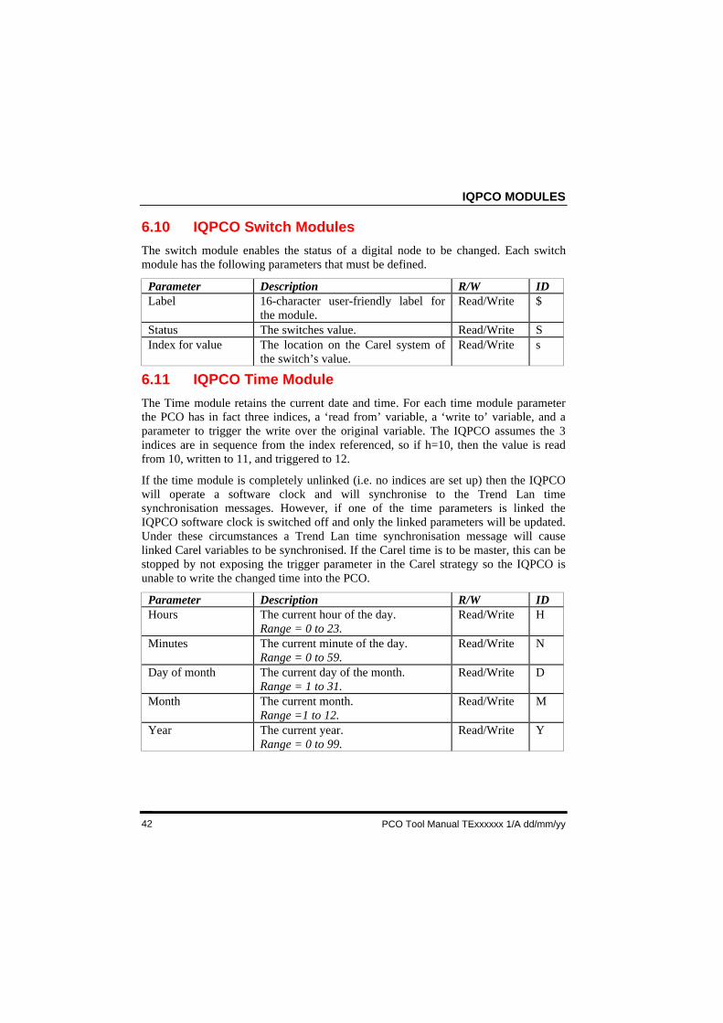
6.10 IQPCO Switch Modules
The switch module enables the status of a digital node to be changed. Each switchmodule has the following parameters that must be defined.
Parameter Description R/W IDLabel 16-character user-friendly label for
the module.Read/Write $
Status The switches value. Read/Write SIndex for value The location on the Carel system of
the switch’s value.Read/Write s
6.11 IQPCO Time Module
The Time module retains the current date and time. For each time module parameterthe PCO has in fact three indices, a ‘read from’ variable, a ‘write to’ variable, and aparameter to trigger the write over the original variable. The IQPCO assumes the 3indices are in sequence from the index referenced, so if h=10, then the value is readfrom 10, written to 11, and triggered to 12.
If the time module is completely unlinked (i.e. no indices are set up) then the IQPCOwill operate a software clock and will synchronise to the Trend Lan timesynchronisation messages. However, if one of the time parameters is linked theIQPCO software clock is switched off and only the linked parameters will be updated.Under these circumstances a Trend Lan time synchronisation message will causelinked Carel variables to be synchronised. If the Carel time is to be master, this can bestopped by not exposing the trigger parameter in the Carel strategy so the IQPCO isunable to write the changed time into the PCO.
Parameter Description R/W IDHours The current hour of the day.
Range = 0 to 23.Read/Write H
Minutes The current minute of the day.Range = 0 to 59.
Read/Write N
Day of month The current day of the month.Range = 1 to 31.
Read/Write D
Month The current month.Range =1 to 12.
Read/Write M
Year The current year.Range = 0 to 99.
Read/Write Y
IQPCO MODULES
PCO Tool Manual Texxxxxx Issue 1/A dd/mm/yy 43
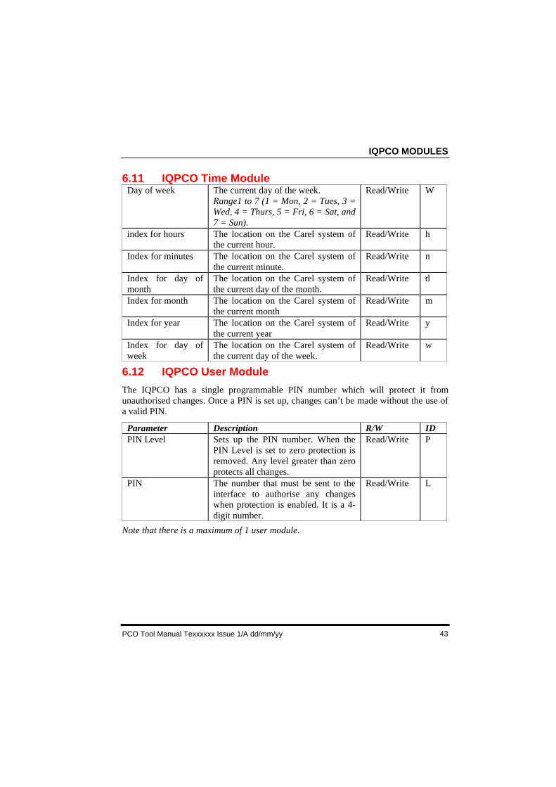
6.11 IQPCO Time ModuleDay of week The current day of the week.
Range1 to 7 (1 = Mon, 2 = Tues, 3 =Wed, 4 = Thurs, 5 = Fri, 6 = Sat, and7 = Sun).
Read/Write W
index for hours The location on the Carel system ofthe current hour.
Read/Write h
Index for minutes The location on the Carel system ofthe current minute.
Read/Write n
Index for day ofmonth
The location on the Carel system ofthe current day of the month.
Read/Write d
Index for month The location on the Carel system ofthe current month
Read/Write m
Index for year The location on the Carel system ofthe current year
Read/Write y
Index for day ofweek
The location on the Carel system ofthe current day of the week.
Read/Write w
6.12 IQPCO User Module
The IQPCO has a single programmable PIN number which will protect it fromunauthorised changes. Once a PIN is set up, changes can’t be made without the use ofa valid PIN.
Parameter Description R/W IDPIN Level Sets up the PIN number. When the
PIN Level is set to zero protection isremoved. Any level greater than zeroprotects all changes.
Read/Write P
PIN The number that must be sent to theinterface to authorise any changeswhen protection is enabled. It is a 4-digit number.
Read/Write L
Note that there is a maximum of 1 user module.
INDEX
PCO Tool Manual TExxxxxx 1/A dd/mm/yy44
INDEX
AboutConventions Used, 5, 13This Manual, 5
About the PCO Tool, 7ToolSETLite, 7
About this Manual, 5Add Modules
Directory Modules, 24, 25Display Modules, 24, 26IC Comms Modules, 22Plot Modules, 21User Modules, 24
Associated Documents, 5Close
PCO Tool, 16Compatibility, 7Connect To
Controller, 30Node Controller, 30Trend Network, 30
Conventions Used in this Manual, 5Create Modules
CDE file, 13Data File, 27Directory Modules, 24Display Modules, 24
Delete a Module, 20Digital Input Module, 34Directory Module, 35Directory Modules, 24Display Area, 11Display Module, 36Display Modules
Set up, 24Download the File, 28Edit a Module, 20Enable/Disable Automatic Editing, 20Engineer a PCO Interface, 13Enter
Unlock Code, 10Enter the Unlock Code, 10Getting Support, 6
IC Comms Module, 37Install
ToolSETLite, 9Installation, 9Introduction, 5IQPCO Address Module, 32IQPCO Digital Input Modules, 34IQPCO Directory Modules, 35IQPCO Display Modules, 36IQPCO IC Comms, 38IQPCO Knob Modules, 39IQPCO Modules, 31IQPCO Plot Modules, 40IQPCO Sensor Modules, 40IQPCO Switch Modules, 42IQPCO Time Module, 42IQPCO User Module, 43Knob Module, 39Licence
Obtain, 9Link the Carel Parameters, 18Load a Project, 15Load the .CDE File, 14Local Supervisor Port, 30Menu Bar, 11Modules
Address, 32Digital Inputs, 34Directory, 35Display, 36IC Comms, 37, 38IQPCO, 31Knob, 39Plot, 40Sensor, 40, 41Switch Modules, 42Time, 42User, 43
Node Controller, 30Obtain a Valid Licence, 9Obtain the Necessary Files, 13Parameters
Text Comms, 32
INDEX
PCO Tool Manual Texxxxxx Issue 1/A dd/mm/yy 45
INDEX (Continued)
PCConnect to Trend Network, 30
Physical Connections, 30Plant View, 24Plot Module, 40Renumber a Module, 20Run
ToolSETLite, 16Run the PCO Tool, 16Save a Project, 15Sensor Module, 40, 41Set up Modules
Address Module, 16Directory Modules, 24Display Modules, 24Time Module, 18
Switch Modules, 42Technical Support, 6
Text Communications Parameters, 32Time Module, 42ToolSETLite Window, 11Tracker Window, 11Tree View, 11Trend
Contacting, 6Unlock Code
Enter, 10User Module, 43User Nodes, 11Using PCO Tool, 13, 14, 15, 16, 18, 20, 21, 22,24, 25, 26, 27, 28
Close PCO Tool, 16Connecting to a Controller or Node
Controller, 30Connecting to Trend Network, 30Install, 9Run, 16