Embed Size (px)
Citation preview
Page 1
Tormach Inc.1071 Uniek Drive, Waunakee, WI 53597Phone: 608.849.8381 / Fax: 209.885.4534
©Tormach® 2016. All rights reserved.Specifications subject to change without notice.TD10420_PCNC440_CoolantControl_Kit_0316A
PCNC 440™ Coolant Control KitProduct Identification: PCNC 440 Coolant Control Kit (PN 37109)
Purpose: This document details installation and use of a coolant control kit on a PCNC 440 mill.
Qty. PCNC 440 Coolant Control Kit PN
1 Coolant Power Supply Assembly —
1 Coolant Relay Assembly —
1 Coolant Fuse Assembly —
1 Coolant Outlet Cable w/ Cord Grip —
NOTE: If any of these items are missing, contact Tormach Customer Service at (608) 849-8381 for a replacement.
Required Tools:
• Flat-head screwdriver • Phillips screwdriver
Electrical Installation
1. Power off mill according to Power Off/On Procedure detailed below.
WARNING! Electrical Shock Hazard: Be sure to power off machine before making any electrical modifications. Failure to do so may result in serious injury or death.
Power Off/On Procedure
Power Off
1. Push red E-stop button in
2. Click Exit on screen; when prompted click OK to power off
3. Turn PathPilot® Controller power strip off
4. Turn Main Disconnect Off (see image at right)
Power On
1. Turn PathPilot Controller power strip on
2. After software loads, turn Main Disconnect On (see image at right)
3. Turn red E-stop button clockwise to release
4. Press green Start button
5. Click Reset on screen
Page 2
Tormach Inc.1071 Uniek Drive, Waunakee, WI 53597Phone: 608.849.8381 / Fax: 209.885.4534
©Tormach® 2016. All rights reserved.Specifications subject to change without notice.TD10420_PCNC440_CoolantControl_Kit_0316A
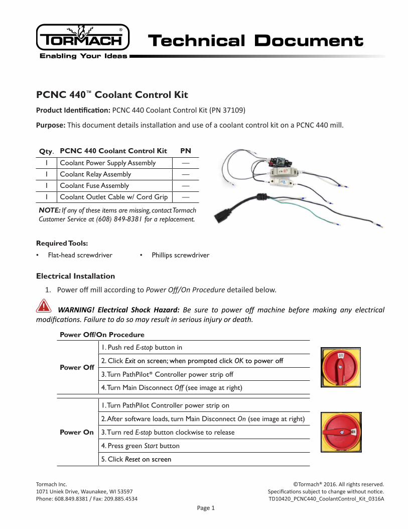
2. Remove electrical cabinet cover from back of mill; set aside.
3. Remove five Wire Trough covers inside electrical cabinet as shown in Figure 1; set aside.
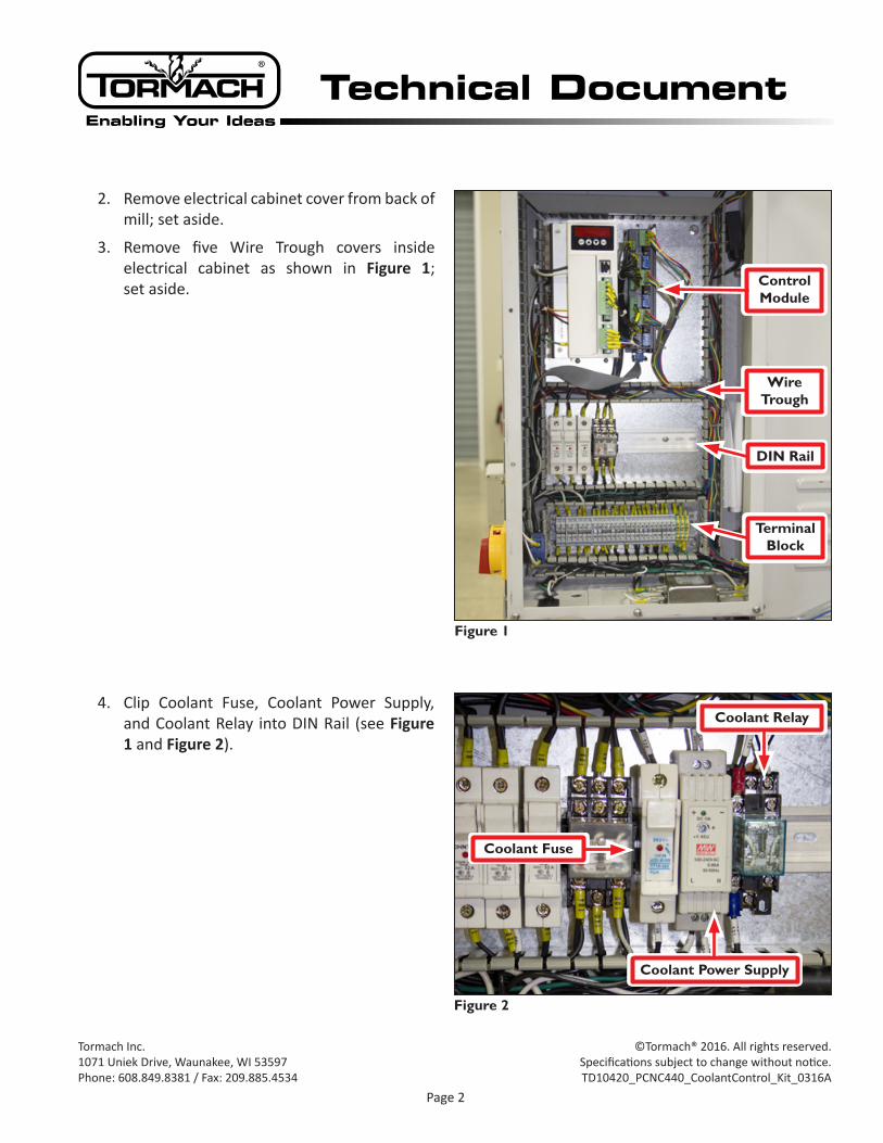
4. Clip Coolant Fuse, Coolant Power Supply, and Coolant Relay into DIN Rail (see Figure 1 and Figure 2).
Figure 1
DIN Rail
Terminal Block
Wire Trough
Control Module
Figure 2
Coolant Fuse
Coolant Relay
Coolant Power Supply
Page 3
Tormach Inc.1071 Uniek Drive, Waunakee, WI 53597Phone: 608.849.8381 / Fax: 209.885.4534
©Tormach® 2016. All rights reserved.Specifications subject to change without notice.TD10420_PCNC440_CoolantControl_Kit_0316A
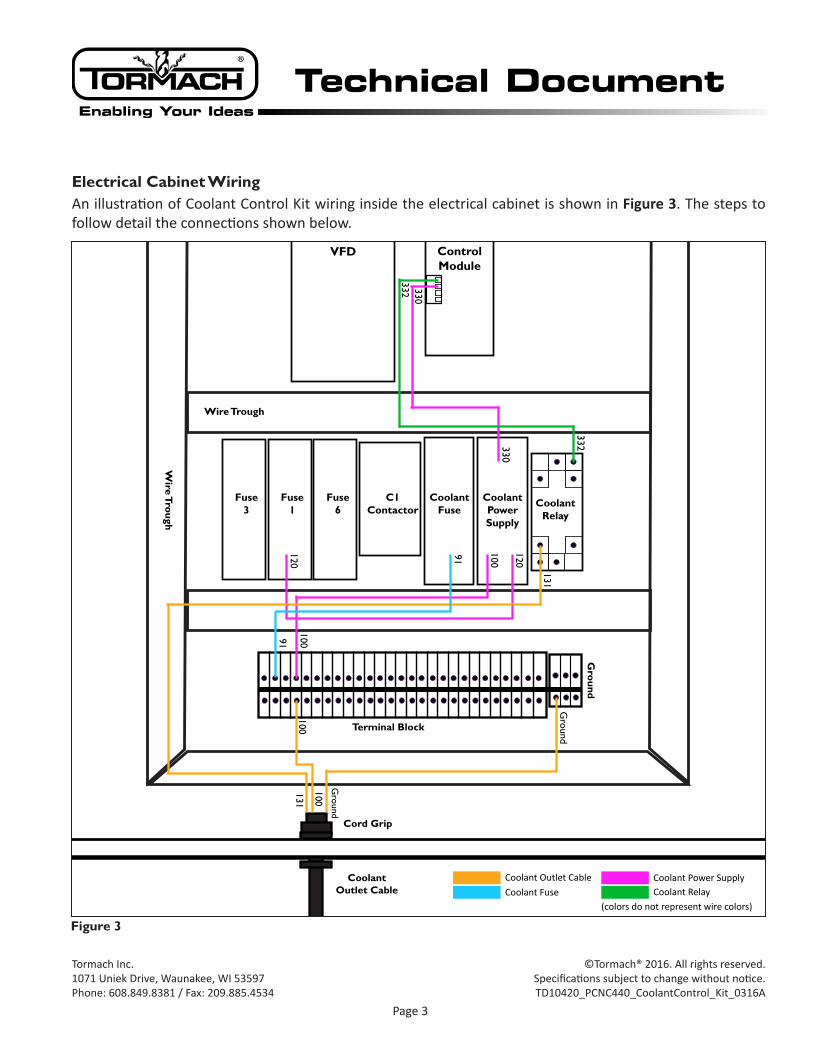
Electrical Cabinet WiringAn illustration of Coolant Control Kit wiring inside the electrical cabinet is shown in Figure 3. The steps to follow detail the connections shown below.
Fuse 3
Wire Trough
Wire Trough
Fuse 1
Fuse 6
Coolant Fuse
C1 Contactor
Coolant Outlet Cable
Cord Grip
Coolant FuseCoolant Outlet Cable
(colors do not represent wire colors)
VFD Control Module
CoolantPower Supply
CoolantRelay
Terminal Block
Ground
Ground
Ground
131
131
100
100
120
120
330
330
332
332
10010091
91
Coolant Power SupplyCoolant Relay
Figure 3
Page 4
Tormach Inc.1071 Uniek Drive, Waunakee, WI 53597Phone: 608.849.8381 / Fax: 209.885.4534
©Tormach® 2016. All rights reserved.Specifications subject to change without notice.TD10420_PCNC440_CoolantControl_Kit_0316A
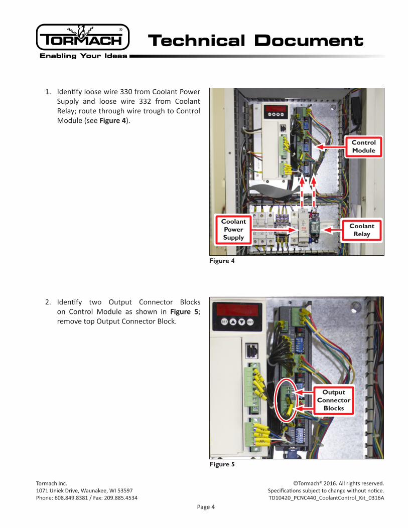
1. Identify loose wire 330 from Coolant Power Supply and loose wire 332 from Coolant Relay; route through wire trough to Control Module (see Figure 4).
2. Identify two Output Connector Blocks on Control Module as shown in Figure 5; remove top Output Connector Block.
Figure 5
Output Connector
Blocks
Figure 4
Coolant Power Supply
Coolant Relay
Control Module
Page 5
Tormach Inc.1071 Uniek Drive, Waunakee, WI 53597Phone: 608.849.8381 / Fax: 209.885.4534
©Tormach® 2016. All rights reserved.Specifications subject to change without notice.TD10420_PCNC440_CoolantControl_Kit_0316A
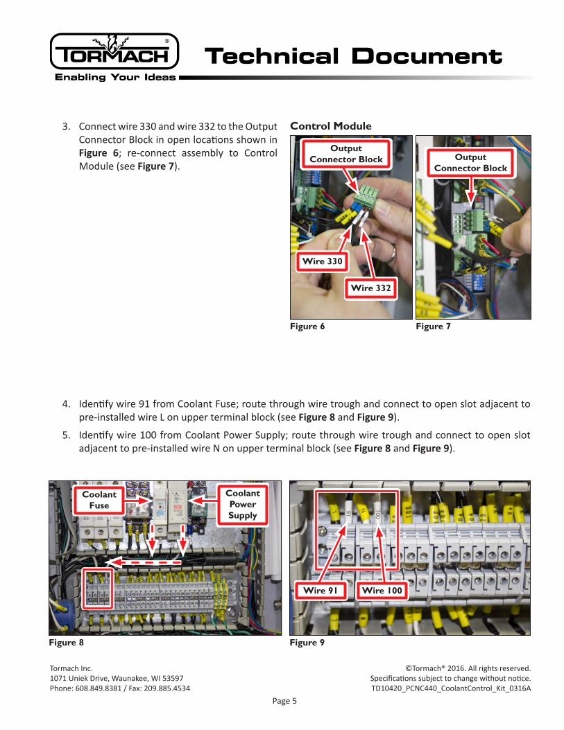
3. Connect wire 330 and wire 332 to the Output Connector Block in open locations shown in Figure 6; re-connect assembly to Control Module (see Figure 7).
4. Identify wire 91 from Coolant Fuse; route through wire trough and connect to open slot adjacent to pre-installed wire L on upper terminal block (see Figure 8 and Figure 9).
5. Identify wire 100 from Coolant Power Supply; route through wire trough and connect to open slot adjacent to pre-installed wire N on upper terminal block (see Figure 8 and Figure 9).
Figure 6
Output Connector Block
Wire 330
Wire 332
Figure 7
Output Connector Block
Control Module
Figure 8
Coolant Fuse
Coolant Power Supply
Figure 9
Wire 91 Wire 100
Page 6
Tormach Inc.1071 Uniek Drive, Waunakee, WI 53597Phone: 608.849.8381 / Fax: 209.885.4534
©Tormach® 2016. All rights reserved.Specifications subject to change without notice.TD10420_PCNC440_CoolantControl_Kit_0316A
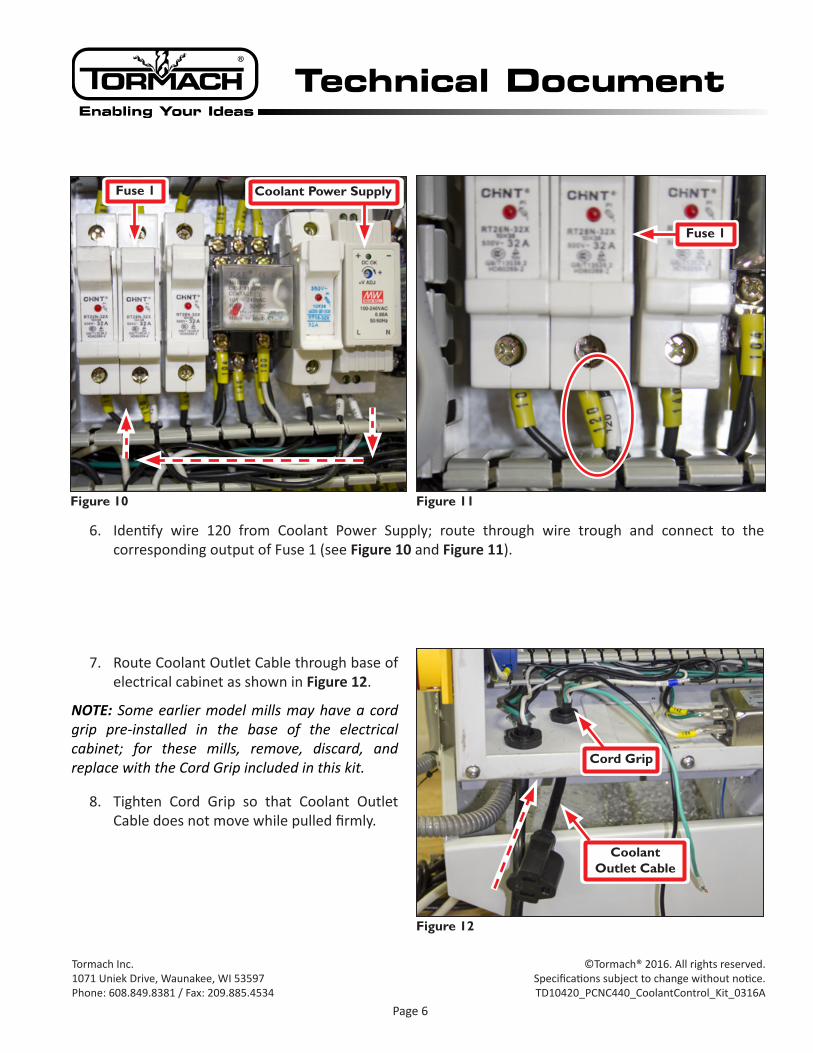
6. Identify wire 120 from Coolant Power Supply; route through wire trough and connect to the corresponding output of Fuse 1 (see Figure 10 and Figure 11).
7. Route Coolant Outlet Cable through base of electrical cabinet as shown in Figure 12.
NOTE: Some earlier model mills may have a cord grip pre-installed in the base of the electrical cabinet; for these mills, remove, discard, and replace with the Cord Grip included in this kit.
8. Tighten Cord Grip so that Coolant Outlet Cable does not move while pulled firmly.
Figure 10
Fuse 1 Coolant Power Supply
Figure 11
Fuse 1
Figure 12
Cord Grip
Coolant Outlet Cable
Page 7
Tormach Inc.1071 Uniek Drive, Waunakee, WI 53597Phone: 608.849.8381 / Fax: 209.885.4534
©Tormach® 2016. All rights reserved.Specifications subject to change without notice.TD10420_PCNC440_CoolantControl_Kit_0316A
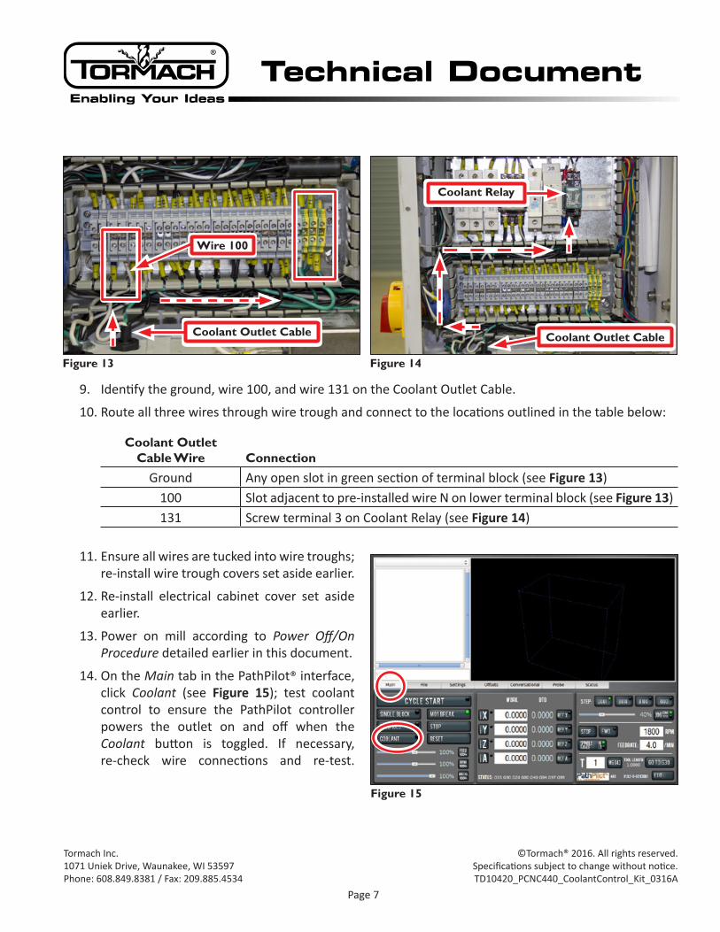
9. Identify the ground, wire 100, and wire 131 on the Coolant Outlet Cable.
10. Route all three wires through wire trough and connect to the locations outlined in the table below:
Coolant Outlet Cable Wire Connection
Ground Any open slot in green section of terminal block (see Figure 13)100 Slot adjacent to pre-installed wire N on lower terminal block (see Figure 13)131 Screw terminal 3 on Coolant Relay (see Figure 14)
11. Ensure all wires are tucked into wire troughs; re-install wire trough covers set aside earlier.
12. Re-install electrical cabinet cover set aside earlier.
13. Power on mill according to Power Off/On Procedure detailed earlier in this document.
14. On the Main tab in the PathPilot® interface, click Coolant (see Figure 15); test coolant control to ensure the PathPilot controller powers the outlet on and off when the Coolant button is toggled. If necessary, re-check wire connections and re-test.
Figure 15
Figure 14
Coolant Relay
Coolant Outlet Cable
Figure 13
Coolant Outlet Cable
Wire 100