Embed Size (px)
Citation preview

NOTICE: This is the author’s version of a work accepted for publication by Elsevier. Changes resulting from the publishing process, including peer review, editing, corrections, structuralformatting and other quality control mechanisms, may not be reflected in this document. Changes may have been made to this work since it was submitted for publication. The definitiveversion has been published in Computer Communications, vol. 34, no. 17, November 2011, doi:10.1016/j.comcom.2011.06.007.
PCN-Based Marked Flow TerminationI
Michael Mentha,∗, Frank Lehriederb
aUniversity of Tübingen, Department of Computer Science, GermanybUniversity of Würzburg, Departement of Computer Science, Germany
Abstract
Pre-congestion notification (PCN) uses packet metering and marking to notify boundary nodes of a Differentiated Services IPnetwork if configured rate thresholds have been exceeded on some links. This feedback is used for PCN-based admission controland flow termination. While admission control is rather well understood, flow termination is a new flow control function and usefulespecially in case of failures or during flash crowds. We present marked flow termination as a new class of termination algorithmswhich terminate overload traffic gradually and that work well with multipath routing. We study their termination behavior, giverecommendation for their configuration, and discuss their benefits and shortcomings.
Keywords: Flow termination, resilience, QoS, Differentiated Services, adaptive systems, performance evaluation
1. Introduction
Network providers and manufacturers have recently recog-nized the need for new admission control concepts for the Inter-net that are simpler and more scalable than the Resource reSer-Vation Protocol (RSVP) [1] in terms of operation and state man-agement. Therefore, the IETF currently standardizes admissioncontrol (AC) and flow termination (FT) for Differentiated Ser-vices IP networks based on pre-congestion notification (PCN).PCN means that routers in a so-called PCN domain meter thetraffic on their links and re-mark packets if the traffic exceedslink-specific rate thresholds. Thereby, boundary nodes of thePCN domain are notified about high load conditions before con-gestion occurs. In contrast to RSVP, PCN scales well becausethe metering and marking algorithms work on aggregates anddo not need to know individual flows.
The AC function admits or rejects new flows based on mea-sured PCN feedback from the network [2] to limit the traf-fic load and to enforce quality of service for already admittedflows. The AC function may fail under difficult conditions, e.g.during flash crowds when the rate of admission requests risessuddenly. Moreover, overload can also appear on backup pathsafter traffic rerouting in case of failures. In such situations, theFT function tears down some already admitted flows and re-stores controlled-load service conditions [3].
While AC methods have been studied intensively in the past,PCN’s FT feature is a new flow control function and only littleunderstood. The current proposals for PCN control [4, 5] usemeasured rate termination (MRT) which we have investigated
IThis work is funded by Nortel Networks, Ottawa, and DeutscheForschungsgemeinschaft (DFG) under grant TR257/18-2. The authors aloneare responsible for the content of the paper.∗Corresponding author.Email address: [email protected] (Michael
Menth)
in [6]. MRT measures the rate of differently marked traffic peringress-egress aggregate (IEA) over an interval and estimatesthe traffic rate to be terminated. Then, a suitable subset of flowsfrom that IEA are terminated in one shot. If too little traffic wasterminated, some more flows may be torn down after a safetyperiod and another measurement period. In case of multipathrouting, MRT is more complex as egress nodes need to recordflows with recently re-marked packets and signal them to cor-responding ingress nodes.
In this paper we propose three different algorithms formarked flow termination (MFT) and evaluate their perfor-mance. We describe their operation, analyze their terminationbehavior, give recommendations for their configuration, andsummarize their pros and cons. In contrast to MRT, they do notterminate flows in one shot but gradually one after another. Fur-thermore, termination is only triggered for flows with markedpackets. This facilitates the use of MFT in networks with multi-path routing without additional modifications which is a strongadvantage over MRT.
Section 2 reviews the current PCN dual marking architectureand gives pointers to related work. In Section 3 we proposethree new MFT methods including assumptions about packetre-marking. Section 4 investigates and compares the threemethods in detail. Section 5 summarizes this work and givesconclusions. A list of frequently used acronyms is provided inthe appendix.
2. Overview of Pre-Congestion Notification
We give an overview of PCN, review the “Controlled Load”(CL) PCN architecture [4], and explain its flow termination indetail. To keep this paper short, we refer the interested readerfor more information about PCN and related work to [7].

PCN Domain
RSVP Capacity Overprovisioning
Source Destination
End-to-end flow
PCN ingress node
PCN egress node
Router with signallingfunctionality
Router with metering & marking functionalityMMS
S/MM
MM
S
End-to-end resource signalling
S/MM
S
S
Figure 1: PCN-based AC is triggered by admission requests from external signalling protocols and guarantees QoS within a single PCN domain.
2.1. Pre-Congestion Notification (PCN)
PCN is intended for use in a single Differentiated Services IPnetwork, a so-called PCN domain. It defines a new traffic classthat receives preferred treatment by PCN nodes and providesinformation to support admission control (AC) and flow termi-nation (FT) for this traffic type. Some end-to-end signallingprotocol (e.g. SIP or RSVP) requests admission for a new flowto cross the PCN domain similarly to the IntServ-over-DiffServconcept [8]. This is illustrated in Figure 1. Traffic enters thePCN domain only through PCN ingress nodes and leaves itonly through PCN egress nodes. The nodes within a PCN do-main are PCN nodes. They monitor the PCN traffic rate ontheir links and possibly re-mark the traffic when certain config-ured rate thresholds are exceeded. PCN egress nodes evaluatethe markings of the traffic and send a digest to the AC and FTdecision points so that they can admit or block new flows oreven terminate already admitted flows. The AC and FT deci-sion points are typically collocated with the ingress nodes of aPCN domain like in the Integrated Services model or reside ina centralized node within a domain like in the IP MultimediaSubsystem (IMS). The AC and FT decisions of a PCN domainare enforced by appropriate filters and per-flow policers at theingress nodes. Only packets of admitted flows receive the prior-itized forwarding treatment of the PCN traffic class and packetsof other flows are blocked when they demand for this premiumservice.
PCN introduces an admissible rate (AR(l)) and a supportablerate (SR(l)) threshold for each link l of a PCN domain. Thesetwo thresholds imply three different link states as illustrated inFigure 2. If the PCN traffic rate r(l) is below AR(l), there is nopre-congestion and further flows may be admitted. If the PCNtraffic rate r(l) is above AR(l), the link is AR-pre-congestedand the traffic rate above AR(l) is AR-overload. In this state,no further flows should be admitted. If the PCN traffic rater(l) is above SR(l), the link is SR-pre-congested and the trafficrate above SR(l) is SR-overload. In this state, some alreadyadmitted flows should be terminated.
Figure 2: The admissible and the supportable rate (AR(l),SR(l)) define threepre-congestion states concerning the PCN traffic rate r(l) on a link.
There are two metering and marking techniques for PCNnodes: threshold marking and excess traffic marking [9]. A(meter and) marker is configured with a reference rate. Ingressnodes label PCN traffic as “not-marked” (NM) to make itdistinguishable from other low priority traffic. Meters mea-sure the rate of PCN traffic and re-mark it when the me-tered PCN traffic rate exceeds their configured reference rate.With threshold marking, all PCN packets are re-marked as“threshold-marked” (ThM) under this condition while excess-traffic-marking re-marks only those PCN packets to “excess-traffic-marked” (ETM) that exceed the configured rate. ETM isstronger than ThM so that ThM packets may be re-marked toETM but not vice-versa [10].
2.2. The “Controlled Load” (CL) PCN Architecture
We review the CL PCN architecture as defined in [4].Threshold markers for each link l in a PCN domain are con-figured with the link-specific admissible rate AR(l) and excesstraffic markers are configured with the supportable rate SR(l).In case of AR-pre-congestion, all PCN packets are re-marked
2

to ThM. In case of SR-pre-congestion, some PCN packets areeven re-marked to ETM and all others are re-marked to ThM.An ingress-egress aggregate (IEA) consists of all flows enteringa PCN domain at a specific ingress and leaving it at a specificegress. Egress nodes measure the rates of differently markedPCN traffic per ingress-egress aggregate using interval-basedmeasurement and send these rates to the AC and FT decisionpoints, i.e., usually to the ingress node of the IEA.
For AC purposes, a decision point calculates the congestionlevel estimate (CLE) which is the fraction of re-marked PCNtraffic. If the CLE exceeds a configured CLE limit, further flowrequests for the corresponding IEA are blocked to avoid over-load. If the CLE falls below the CLE limit, new flows can againbe admitted.
FT works as follows. When a decision point receives a rateof ETM traffic larger than zero, it requests the rate of sent PCNtraffic from the ingress node (ingress rate IR). It calculates thetermination rate as the difference between the ingress rate andthe non-ETM traffic rate (sum of NM traffic rate and ThM traf-fic rate). Then, it chooses a set of flows whose overall rateequals the termination rate and terminates these flows.
2.3. Measured Rate Termination (MRT)
We call the termination approach described above “measuredrate termination” (MRT) because the amount of traffic to be ter-minated is determined by rate measurement. We have investi-gated this method in [6] and identified the following problems.
To get sufficiently accurate measurement results, the mea-surement interval needs to be long enough which introducesdelay in the order of several hundreds milliseconds. The FTdecision point needs relatively good estimates about the flowrates. Wrong estimates easily lead to overtermination or under-termination because MRT terminates the traffic in one shot. Inthe latter case, another termination step is required. However, aminimum inter-termination time between two consecutive ter-mination steps must be respected to make sure that terminatedflows do not contribute anymore to the measured feedback.This further delays the termination process. Moreover, IEA-based traffic measurements are sometimes considered heavy-weight and undesirable.
When an IEA carries only a small number of flows and onlysome ETM-packets are received by the egress node, it is hardto decide whether none or one flow should be terminated, butthe result matters. We have suggested proportional terminationto solve that problem. In case of multipath routing, e.g. ECMP,flows of the same IEA are possibly carried over different paths.As a consequence, MRT possibly tears down flows that do notcontribute to SR-overload until also some flows are terminatedthat have caused the observed SR-pre-congestion. This can berepaired if the egress node provides information about flowswith recently marked packets to the FT decision point.
MRT requires the notion of an IEA to perform per-IEA ratemeasurement, but it is not yet clear how flows belonging to aspecific IEA are recognized. End-to-end PCN has been intro-duced in [11, 7]. It allows only definition of trivial IEAs (singleflows), so that MRT does not seem appropriate in that context.
PCN domain
PCN
egress
node
PCN
ingress
node
PCN
interior
node
Link l
(SR(l) exceeded)
IEA Marked
packet
Figure 3: Basic functionality of FT mechanisms. In case of SR-pre-congestion,PCN interior nodes re-mark packets as excess-traffic-marked. PCN egressnodes evaluate these markings and possibly trigger the termination of flows.
3. Marked Flow Termination (MFT)
In this section we present marked flow termination (MFT) asan alternative to measured rate termination (MRT). Due to theshortcomings of MRT, it is of interest to explore other PCN-based flow termination methods that avoid the shortcomings ofMRT by design which is the case for marked flow termination(MFT).
When SR-pre-congestion occurs, packets are excess-traffic-marked. In the following, we just say “marked” for the sakeof brevity. MFT methods terminate only “marked flows”, i.e.those with at least one recently marked packet. In the following,we propose three different methods for MFT including modifi-cations of the marking algorithms if needed. The basic func-tionality of FT mechanisms is illustrated in Fig. 3.
3.1. Marked Flow Termination Based on Excess Traffic Mark-ing with Marking Frequency Reduction (MFT-MFR)
The idea of this approach is that the egress node triggers thetermination of a flow as soon as it has received a marked packetfor that flow. However, the existing algorithm for excess trafficmarking re-marks so many packets to ETM that too many flowsare terminated with this idea. Therefore, we reduce the markingfrequency of excess traffic marking by a factor to control thetermination aggressiveness of the MFT algorithm that we callMFT with marking frequency reduction (MFT-MFR). We havediscussed this idea for the first time in [12].
In the following, we present the base algorithm for excesstraffic marking, our modification for packet-size independentmarking (PSIM), an extension for marking frequency reduc-tion (MFR), as well as a modification for proportional MFR(PMFR).
3.1.1. Plain Excess Traffic MarkingAlgorithm 1 uses a token bucket based formulation to de-
scribe the behavior of the excess traffic marker. It is called ateach packet arrival. The marker has a token bucket which isS bytes large and constantly filled with tokens at rate R. The
3

Input: token bucket parameters S, R, F , lastU ,packet size B and marking M, current timenow, maximum transfer unit MTU (onlyneeded for PSIM), increment I (for MFR) orstretch factor βα (for PMFR)
F = min(S,F +(now− lastU) ·R);lastU = now;if (F ≥ B) then {PSIM: (F ≥MTU)}
F = F−B;else
M = ET ;end ifif (M == ET ) then {Marking frequency reduction}
F = min(S,F + I); {PMFR: F = min(S,F +βα ·B);}end if
Algorithm 1: EXCESS TRAFFIC MARKING: base algorithmwith extension for marking frequency reduction (MFR) andmodification for packet size independent marking (PSIM) aswell as proportional MFR.
token bucket variable lastU records the time of the last updateand helps to account for the number of new tokens that havebeen generated since the last call of the algorithm. If the fillstate F of the bucket is at least the size B of the arrived packet,B tokens are removed from the bucket; otherwise, the markingof the packet is set to M = ET M.
3.1.2. Excess Traffic Marking with Packet Size IndependentMarking (PSIM)
Plain excess traffic marking marks larger packets with ahigher probability than smaller packets. This may lead to highertermination probabilities for flows with larger packets. There-fore, we propose to make the marking decision in Algorithm 1independent of the packet size. PSIM marks a packet already ifthe fill state is lower than the maximum transfer unit (MTU) ofthe link. This assures that the marking probability is indepen-dent of the packet size B. This modification is beneficial also toother flow termination methods and has also been adopted by[9] as an explicit implementation option.
3.1.3. Excess Traffic Marking with Marking Frequency Reduc-tion (MFR)
Plain excess traffic marking re-marks all traffic whose rateexceeds the reference rate of the marker. We present an exten-sion that reduces the frequency at which packets are re-markedin a controllable way. It is expressed by the last if-statement inAlgorithm 1. If the packet is marked, MFR adds an incrementof I bytes to the bucket. This is done regardless of whetherthe packet was marked by the current or a previous node. Thisalgorithm can be easily combined with PSIM.
3.1.4. Excess Traffic Marking with Proportional MFR (PMFR)As we will see later, it is beneficial if the increment I used by
excess traffic marking with MFR is proportional to the packetsize B. Therefore, excess traffic marking with proportional
MFR uses a stretch factor βα which is multiplied by the packetsize B to yield the increment. This is also reflected in Algo-rithm 1.
3.2. Marked Flow Termination Based on Plain Excess TrafficMarking for Individual Flows (MFT-IF)
MFT-IF requires plain excess traffic marking with packet sizeindependent marking (PSIM). Therefore, it is compatible withthe currently discussed standards proposal [4]. The egress nodeof a flow f sets up a flow-specific credit counter C f . If a flow’spacket arrives marked and its credit counter is positive, its creditcounter is decreased by the size of the packet. If the counter iszero or negative at the arrival of an ETM packet, the flow isterminated. In contrast to MFT-MFR, this method permits toimplement stochastic termination priorities by choosing largervalues for the credit counter initialization for high-priority flowsthan for low-priority flows.
3.3. Marked Flow Termination Based on Plain Excess TrafficMarking for Ingress-Egress Aggregates (MFT-IEA)
MFT-IEA groups flows sharing a common PCN ingress andegress node into a common IEA. We denote the flow set of suchan IEA g by F(g). The PCN egress node has a credit counterCg for each of its IEAs g. When the PCN egress node receivesa marked packet that belongs to a flow f ∈ F(g), the packet’ssize in bytes is subtracted from the counter Cg. If the counteris not positive at the arrival of a marked packet, the flow f isterminated. In this case, the credit counter is decreased by thepacket size and increased by an increment Iα = σb which isproportional to the flow rate R f . Like with MFT-IF, flow ter-mination priorities can be implemented. However, terminationpriorities can be enforced more effectively with MFT-IEA thanwith MFT-MFR or MFT-IF because MFT-IEA can choose theflow to be terminated from the set of recently marked flows.
An alternative design terminates a flow already if the size ofthe marked packet is larger than the credit counter. On the onehand this is simpler, but on the other hand it leads to packetsize dependent termination probabilities that we want to avoid.Hence, our design complements PSIM in the core and also in-fluenced the design of the MFT-IF mechanism. We have dis-cussed this idea for the first time in [13].
4. Performance Evaluation and Comparison of MFT Meth-ods
In this section we first explain our simulation methodology.We investigate the three presented MFT methods one after an-other and give recommendations for their configuration. Wethen compare the three methods under various conditions, sum-marize our results, and briefly comment on other work aboutMFT.
4.1. Simulation Setup
We investigate the termination behavior of MFT on a linkthat faces sudden overload as it is the case, e.g., after trafficreroutes or flash-crowd arrivals. We do not simulate complex
4
network topologies, but abstract from an entire network to asingle link that is suddenly faced with an overload condition.This simplifies and speeds up the simulation. It still permitsconclusions about the termination behavior because we modelthe message delay which is normally caused by the missing net-work elements by an appropriate flow termination delay DT .If not mentioned differently, we use the following default pa-rameters for our experiments. We use simple constant bit rateflows because they are more appropriate to find and visualizebasic effects of the mechanisms under study. The flows havedeterministic inter-arrival times A with E[A] = 20 ms1 and de-terministic packet sizes B with E[B] = 200 bytes. Thus, flowrates are E[R] = 80 kbit/s. To avoid simulation artifacts due tomarking synchronization for periodic traffic, we add an equallydistributed random delay of up to 1 ms to the theoretic arrivalinstant of every packet. This traffic model is realistic becauserealtime applications send traffic periodically, but packets mayarrive at the bottleneck link with some jitter.
When the egress node decides to terminate a flow, it quicklyinforms the ingress node to reconfigure appropriate filters. Weintroduce the concept of the flow termination delay DT . It is thetime between the decision of the egress node until it no longerreceives packets from the terminated flow. The round-trip timewithin a PCN domain gives a lower bound on that value butDT may be larger due to management overhead at ingress andegress node. In our study we assume DT = 50 ms for localnetworks, DT = 200 ms for national networks, and DT = 500ms for transatlantic or satellite networks.
We simulate the time-dependent PCN traffic rate r(t) of alink to study the termination process of the time-dependent SR-overload SRO(t). The supportable link rate is SR = 8 Mbit/sand the simulation starts with n = 200 admitted flows which isr(0) = 16 Mbit/s. This corresponds to an initial SR-overload of100%, i.e., the initial SR-overload is also SRO(0) = 8 Mbit/s.Thus, half of the flows need to be terminated. The token bucketrate R= SR(l) is set to the supportable rate of the monitored linkl and its bucket size is set to a sufficiently large value which isS = 50 KB in our simulations.
We use a custom-made Java tool to simulate the time-dependent PCN rate r(t) to illustrate the termination behav-ior. This rate is calculated based on 50 ms long measurementintervals. We perform multiple experiments and report aver-age results for the termination behavior in our figures. We runso many simulations that the 95% confidence intervals for thetime-dependent PCN rate values r(t) are small. However, weomit them in the figures for the sake of easier readability.2
4.2. MFT with Marking Frequency Reduction (MFR)
We investigate the performance of MFT-MFR that we pre-sented in Section 3.1. We first motivate an appropriate value
1E[X ] is the mean and cvar[X ] the coefficient of variation of a random vari-able X .
2Even in case of strictly periodic traffic, i.e., the inter-arrival times and thesizes of the packets are constant, different runs produce different results becausethe first transmission of a flow within a first inter-arrival time after simulationstart is random.
0
2
4
6
8
10
12
14
16
18
0 0.2 0.4 0.6 0.8 1 1.2 1.4 1.6 1.8 2
PC
N tr
affic
rat
e r(
t) (
Mbi
t/s)
Time t (s)
SR(l)
α=4
α=2
α=1
α=0.5
α=0.25
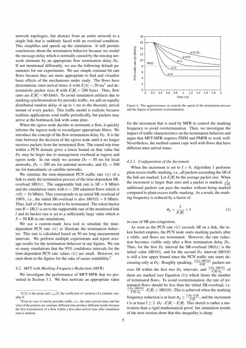
Figure 4: The aggressiveness α controls the speed of the termination processand the degree of potential overtermination.
for the increment that is used by MFR to control the markingfrequency to avoid overtermination. Then, we investigate theimpact of traffic characteristics on the termination behavior andargue that MFT-MFR requires PSIM and PMFR to work well.Nevertheless, the method cannot cope well with flows that havedifferent inter-arrival times.
4.2.1. Configuration of the IncrementWhen the increment is set to I = 0, Algorithm 1 performs
plain excess traffic marking, i.e., all packets exceeding the SR ofthe link are marked. Let E[B] be the average packet size. Whenthe increment is larger than zero and a packet is marked, I
E[B]additional packets can pass the marker without being markedcompared to plain excess traffic marking. As a result, the mark-ing frequency is reduced by a factor of
σp =I
E[B]+1 (1)
in case of SR-pre-congestion.As soon as the PCN rate r(t) exceeds SR on a link, the to-
ken bucket empties, the PCN node starts marking packets aftera while, and flows are terminated. However, the rate reduc-tion becomes visible only after a flow termination delay DT .Thus, for the first DT interval the SR-overload SRO(t) is theinitial value SRO(0), and for the second DT interval SRO(0)is still a low upper bound since the PCN traffic rate starts de-creasing only at DT . Roughly speaking, 2·DT ·SRO(0)
E[B] packets are
over SR within the first two DT intervals, and 2·DT ·SRO(0)E[B]·σp
ofthem are marked (see Equation (1)) which limits the numberof terminated flows. To avoid overtermination, the rate of ter-minated flows should be less than the initial SR-overload, i.e.2·DT ·SRO(0)
E[B]·σp·E[R]≤ SRO(0). This is achieved when the marking
frequency reduction is at least σp ≥ 2·DT ·E[R]E[B] , and the increment
I is at least I ≥ 2 ·DT ·E[R]−E[B]. This sketch is rather a mo-tivation than a rigid mathematical proof, but simulation resultsof the next section show that this inequality is sharp.
5

4.2.2. Termination Aggressiveness α
To control the speed of the termination process, we introducethe aggressiveness α and use it to control the size of the incre-ment by
Iα =2 ·E[DT ] ·E[R]−E[B]
α. (2)
The aggressiveness is defined such that the termination speedincreases with α and that overtermination is avoided for α < 1,at least for homogeneous traffic. This is illustrated in Figure 4.The degree of overtermination also increases with α . To keepMFT-MFR simple, the increment Iα may be configured in thePCN nodes only once based on estimated values E[B∗], E[R∗],E[D∗T ], and a desired α∗, and it is not adjusted to the currenttraffic characteristics. In the following, we study such systemsunder different conditions.
4.2.3. Impact of Different Packet Sizes – Homogeneous TrafficWe configure Iα according to Equation (2) for the default val-
ues in Section 4.1, in particular E[B∗] = 200 bytes and α∗ = 1,but vary the actual packet sizes E[B] which affects the actualflow rate E[R]. This leads to an actual termination aggressive-ness α = 2·E[DT ]·E[R]−E[B]
I∗α= α∗ · E[B]
E[B∗] . As a result, the resultingtermination behavior can be essentially derived from Figure 4for given E[B]. Hence, the termination behavior of MFT-MFRsignificantly depends on the average packet sizes. However, itis possible to make it independent of the packet size by apply-ing in the PCN nodes proportional marking frequency reduction(PMFR) as described in Algorithm 1. The increment is thencalculated by
Iα =2 ·E[DT ] · 1
E[A] −1
α·B = βα ·B (3)
using the stretch factor βα . Thus, the increment is proportionalto the size of the observed marked packet. Now, one packet ismarked for
σb = βα ·E[B]+E[B] =2 ·E[DT ] ·E[R]
α(4)
bytes that have been above SR during a continuous SR-pre-congestion phase. This means that also one flow is terminatedfor that amount of bytes that have exceeded SR. Therefore,PMFR makes the termination behavior of MFT-MFR indepen-dent of the packet size E[B]. We validated this finding by simu-lation but we do not show any figures. In the remainder of thiswork, we use PMFR for the study of MFT-MFR.
4.2.4. Impact of Different Packet Sizes – Heterogeneous TrafficWe consider constant bit rate flows with an average bit rate
of E[R] = 80 kbit/s, but the bit rate of different flows varies.The flows have all the same inter-arrival time of A = 20 ms, butdiffer in packet size according to Table 1. The parameter t de-termines the proportion of low, medium, and high bit rate flowsin the traffic mix. The parameter t controls the variability of theflow-specific packet sizes, so that the corresponding coefficientof variation is cvar[R] = 1.5 ·
√t.
Table 1: Traffic mixes with E[R] = 80 kbit/s and cvar[R] = 1.5 ·√
t. The variablet controls the proportion of low, medium, and high bit rate flows in the trafficmix. Either packet size or inter-arrival time is varied, but not both.
Flow typesFlow type specific low bit rate medium bit rate high bit rate
Proportion 0.8 · t 1− t 0.2 · tE[B] for E[A] = 20 ms 50 bytes 200 bytes 800 bytesE[A] for E[B] = 200 bytes 80 ms 20 ms 5 msRate E[R] 20 kbit/s 80 kbit/s 320 kbit/s
We conducted experiments and found that the terminationbehavior for highly variable traffic mixes (t = 1) is almost thesame as for traffic with homogenous packet sizes (t = 0, seeFigure 4). However, Table 2 shows that flows with large packetshave a tremendously higher termination probability than flowswith small packets. Therefore, we use from now on packetsize independent marking (PSIM, see Section 3.1.2). With thischange, low, medium, and high bit rate flows face the sametermination probability and the termination behavior is still in-dependent of the traffic mix.
Table 2: Flow termination probabilities depending on packet size B and inter-arrival time A for the experiments in Section 4.2.4 and Section 4.2.6.
Traffic Different B, α = 1, PMFR without PSIMmix E[B] = 50 bytes E[B] = 200 bytes E[B] = 800 bytes
t = 0 - 0.501 -t = 0.5 0.023 0.247 0.942t = 1 0.006 - 0.625
Traffic Different A, α = 0.5, see Figure 5mix E[A] = 80 ms E[A] = 20 ms E[A] = 5 ms
t = 0 - 0.494 -t = 0.5 0.119 0.348 0.792t = 1 0.077 - 0.630
4.2.5. Impact of Packet Inter-Arrival Times – HomogeneousTraffic
We configure the stretch factor βα of Equation (3) againbased on the default values given in Section 4.1, in particularE[A∗] and α∗ = 1, but vary the actual packet inter-arrival timeA for all flows which affects the average flow rate E[R]. Thisleads to a different aggressiveness α = E[A∗]
E[A] ·α∗. Increasing
the actual inter-arrival time decreases the aggressiveness andvice-versa. Hence, the termination behavior of MFT-MFR sig-nificantly depends on the actual packet inter-arrival times E[A]and looks like the curves in Figure 4 for different α .
In practice we need a viable solution that reduces the SR-overload quickly while avoiding overtermination. Most real-time applications send one packet within 20 ms, some othershave a period of 10 ms. Video applications are slower but pos-sibly send several packets for one frame. We recommend touse an aggressiveness of α = 0.5 and an inter-arrival time of
6

0
2
4
6
8
10
12
14
16
18
0 0.2 0.4 0.6 0.8 1 1.2 1.4 1.6
PC
N tr
affic
rat
e r(
t) (
Mbi
t/s)
Time t (s)
SR(l)
t=0
t=0.5
t=1
Figure 5: Traffic with more variable inter-arrival times leads to faster termina-tion and flows with shorter inter-arrival times have higher termination probabil-ities.
E[A] = 20 ms for the configuration of the stretch factor in Equa-tion (3). This corresponds to an aggressiveness of α = 1 forE[A] = 10 ms such that overtermination is not likely to occurwith today’s applications. If the actual inter-arrival time is infact E[A] = 20 ms, the reduction of SR-overload to about 10%is still fast as it takes only 1.7 s (see Figure 4, α = 0.5).
4.2.6. Impact of Packet Inter-Arrival Times – HeterogeneousTraffic
We study the impact of traffic mixes consisting of differentconstant bit rate flows according to Table 1. The packet sizesand inter-arrival times within a single flow are constant, but dif-ferent flows have different packet inter-arrival times. The av-erage inter-arrival time over all flows is E[A] = 20 ms, but itsvariability depends on t. We configure the stretch factor βα
based on an aggressiveness α = 0.5. Figure 5 shows that thetermination speed depends on the traffic mix: more variableinter-arrival times lead to faster termination. Table 2 shows thatflows with small packet inter-arrival times have a tremendouslylarger flow termination probability. This is due to the fact thatthe probability for a flow to have a marked packet increaseswhen it sends more packets. Since large flows are more likelyto be terminated first, the termination process for heterogeneoustraffic is faster than for homogeneous traffic and prone to overt-ermination. However, overtermination is almost fully avoidedin the experiment because the aggressiveness α = 0.5 is chosenlow enough. Unfortunately, we do not know any simple mech-anism to balance the termination probability among flows withdifferent inter-arrival times.
4.3. Performance Evaluation of MFT for Individual Flows(MFT-IF)
We investigate the performance of MFT-IF that we presentedin Section 3.2. We first propose a suitable initialization methodfor the flow-specific credit counters. The termination processcan be well controlled for heterogeneous flows when reasonableestimates of their rates are available. We show that it is possibleto implement stochastic termination priorities.
0
0.2
0.4
0.6
0.8
1
0 5 10 15 20
CC
DF
P(C
>x)
Initial counter value x (KB)
P(C>x)=e-x/σb
P(C>Ci), n=10
P(C>Ci), n=30
Figure 6: CCDF of the counter initialization values for a various number of nflows and their limiting function.
4.3.1. Counter InitializationWe suggest a method for the initialization of the credit coun-
ters. We borrow ideas from our analysis of MFT-MFR. MFT-MFR’s termination speed is controlled by the fact that the nextpacket is excess-traffic-marked only after σb bytes have ex-ceeded SR since the last packet was marked (see Equation (4)).We mimic this behavior by initializing the credit counters forMFT-IF appropriately so that the resulting termination behav-ior for MFT-IF is the same as for MFT-MFR.
We consider n flows numbered from i = 1 to n and havingdifferent counter initialization values Ci with Ci−1 <Ci. We as-sume that they receive equally many marked bytes in case ofSR-pre-congestion. As a consequence, flows terminate in as-cending order. When flow i terminates next, n− (i− 1) flowsare still active. To let σb marked bytes pass between the termi-nation of flows i−1 and i, the difference between their countersshould be set to Ci−Ci−1 =
σbn−(i−1) . With C0 = 0, the counter
initialization should be chosen
Ci = ∑0<k≤i
σb
n− (k−1)= σb · (Hn−Hn−i) = σb · ln(
nn− i
) (5)
with Hi = ∑0<k≤i1k being the i-th harmonic number for which
the approximation Hi ≈ ln(i)− γ holds when i is finite.3 Ex-periments with this credit counter initialization show the sametermination behavior as in Figure 4.
Equation (5) can be used to initialize the credit counter offlows if all flows sharing a single bottleneck link are known.Now we develop an algorithm which allows a flow to initial-ize its credit counter randomly without knowing anything aboutother flows. Based on Equation (5), the complementary cumu-lative distribution function (CCDF) of the counter initializationvalues for n flows is P(C > Ci) = P(C > σb · ln( n
n−i )) =n−i
n .Substituting σb · ln( n
n−i ) by x we get
P(C > x) = exp(−xσb
)= exp
(−x ·α
2 ·E[DT ] ·E[R]
)(6)
3γ = 0.57721... is the Euler-Mascheroni constant.
7

0
2
4
6
8
10
12
14
16
18
0 0.5 1 1.5 2 2.5
PC
N tr
affic
rat
e r(
t) (
Mbi
t/s)
Time t (s)
SR(l)
w/o prio with prio
low prio (α=1)
high prio (α=0.25)
Figure 7: Termination behavior for high and low priority traffic.
for large n. Figure 6 illustrates that the exact CCDFs for vari-ous numbers of flows n converge quickly towards the limitingCCDF of Equation (6). Therefore, we propose that a new flowf takes its own rate R f as an estimate for E[R] and randomlyinitializes its credit counter according to Equation (6). It picksa uniformly distributed random number 0 < y < 1 and sets itscredit counter to C f =−
2·E[DT ]·R fα
· ln(y).When we substitute the deterministic initialization accord-
ing to Equation (5) by the stochastic initialization according toEquation (6), we expect less control or at least more varianceof the termination behavior. However, we tested this issue andfound that the deviation from the average termination behavioris rather small. More evidence on the variability of the termina-tion behavior is given in Section 4.5.5.
4.3.2. Impact of Packet Sizes and Inter-Arrival TimesWe conducted experiments and found that the termination
behavior for MFT-IF is robust against traffic mixes consistingof flows with different packet sizes and inter-arrival times. Thecounter initialization takes the issue of different bit rates intoaccount by using the flow rate R f . We also found that flowswith different packet sizes or packet inter-arrival times face thesame termination probabilities.
4.3.3. Implementation of Stochastic Flow Termination Priori-ties
The initialization value of its credit counter heavily impactsthe termination probability of a flow in case of SR-overload.Therefore, high priority flows should be assigned larger ini-tial credit counters than low priority flows to have a betterchance to survive SR-pre-congestion. We achieve that by us-ing a smaller aggressiveness α to initialize the credit countersof high-priority flows.
We consider low-priority flows for which we use α = 1 andhigh-priority flows for which we use α = 0.25. Figure 7 showstheir individual and combined termination behavior. While theaggregate rate of low-priority flows is significantly reduced, theaggregate rate of high-priority flows is less decreased. Thus,high-priority flows have indeed a lower termination probabil-ity than low-priority flows. The dashed line is the termination
behavior without prioritized flows (α = 1). It shows that prior-itization prolongs the duration of the termination process.
4.4. Performance Evaluation of MFT for Ingress-Egress Ag-gregates (MFT-IEA)
We investigate the performance of MFT-IEA that we pre-sented in Section 3.3. We first propose a suitable initializationmethod for the IEA-specific credit counters. We study the im-pact of the size of IEAs, packet size, and inter-arrival time onthe termination process and evaluate to what extent terminationpolicies can be enforced.
4.4.1. Configuration of MFT-IEAWhen a first flow joins the IEA g after system start, Equations
(4) and (6) may be used to randomly initialize the credit counterCg. To implement a similar control as for MFT-IF, we choosean increment of
Iα = σb =2 ·DT ·R f
α(7)
when a flow is terminated. Note that this equation differs fromEquation (3) by the fact that the increment is proportional to theflow rate R f instead of the packet size.
4.4.2. Impact of the Size of IEAsWe conduct experiments where the n = 200 flows on the bot-
tleneck are grouped into different IEAs with m∈ {1,4,20,200}flows each. They all lead to about the same termination behav-ior as in Figure 4. Therefore, we omit the figure for these ex-periments. The termination process for IEAs of size m = 1 juststarts 20 ms later than for m= 200. In fact, for m= 1, MFT-IEAbecomes MFT-IF and shows the identical termination behavior.
4.4.3. Impact of Packet Sizes and Inter-Arrival TimesWe conducted experiments that show that the termination be-
havior of MFT-IEA and the flow termination probabilities areinsensitive to the average packet size and its variation withinflows.
This is slightly different for inter-arrival times. Flows witha higher packet frequency have a higher termination probabil-ity since it is more likely that one of their marked packets seesa non-positive credit counter at their arrival compared to flowswith a lower packet frequency. We show this phenomenon byan experiment. We consider traffic mixes of flows having differ-ent inter-arrival times according to Table 1 and flows of differ-ent types are equally assigned to IEAs with m = 20 flows. Ta-ble 3 illustrates that the termination probabilities of high bit rateflows are larger than those for low bit rate flows. This is simi-lar to MFT-MFR where different flow termination probabilitiesalso impact the termination behavior (see Figure 5). We nowconsider the termination behavior. In contrast to MFT-MFR,with MFT-IEA the termination behavior for heterogeneous traf-fic hardly differs from the one of homogeneous traffic (withoutfigure). This is due to the fact that MFT-MFR’s increment isonly proportional to the packet size of the terminated flow whileMFT-IEA’s increment defined in Equation (7) is proportional toits rate.
8

Table 3: Flow termination probabilities for MFT-IEA depending on the trafficmix. All flows have a fixed packet size of 200 bytes but different inter-arrivaltimes.
Rate 20 kbit/s 80 kbit/s 320 kbit/sE[A] 80 ms 20 ms 5 mst = 0 - 0.507 -
t = 0.5 0.096 0.317 0.861t = 1 0.060 - 0.647
When we group the heterogeneous flows in such a way thatIEAs have only flows with equal inter-arrival times, the effect ofdifferent termination probabilities vanishes. Thus, defining sub-IEAs for flows with homogenous inter-arrival times restoresequal termination probabilities for all flows.
4.4.4. Stochastic Enforcement of Termination PoliciesStochastic termination priorities can be implemented sim-
ilarly as in Section 4.3.3: low and high priority flows aregrouped into different IEAs that are configured with larger andsmaller aggressiveness. In addition to such termination prior-ities, we propose stochastic enforcement of termination poli-cies. When a marked packet arrives and the credit counter isnot positive, a flow must be terminated. However, this is notnecessarily the flow to which the newly arrived packet belongsto. Basically, any other flow from the same IEA can be termi-nated. However, to cope with multipath routing, the other flowmust have been recently marked, too. Thus, MFT-IEA needs torecord the set of marked flows and can choose a flow from thisset according to some policy when a flow needs to be termi-nated. We call this stochastic policy enforcement because theflows to be terminated have to be chosen from the set of recentlymarked flows, and the composition of this set is stochastic.
Table 4: Flow termination probabilities for MFT-IEA and different policiesdepending on the number of flows per aggregate m.
Rate 40 kbit/s 160 kbit/s 40 kbit/s 160 kbit/s 40 kbit/s 160 kbit/s
m No priorities Large flows first Small flows first
250 0.286 0.721 0.037 1.000 0.987 0.06725 0.275 0.741 0.029 0.986 0.962 0.1325 0.186 0.827 0.047 0.929 0.809 0.379
We perform some experiments to show the effectiveness ofstochastic policy enforcement. In the first experiment, we con-sider 200 flows with 40 kbit/s (E[A] = 40 ms) and 50 flows with160 kbit/s (E[A] = 10 ms) so that half of the traffic volume re-sults from low and high bit rate flows. We group them equallyinto aggregates with m ∈ {5,25,250} flows. Table 4 showsthat when no policy is applied, large flows have a significantlyhigher termination probability due to their larger packet fre-quency. When large flows are terminated first, only 2.9%–4.7%of the small flows are terminated but 92.9%–100% of the largeflows. In contrast, when small flows are terminated first, 6.7%–37.9% of the large flows are still terminated and 80.9%–98.7%
of the small flows. The table also shows that stochastic policyenforcement is more effective for larger aggregates. Thus, theeffectiveness of stochastic policy enforcement depends both onthe aggregation level of the IEA and the policy itself.
4.5. Performance Comparison of MFT MethodsIn this section, we study aspects that are common to all three
MFT methods: MFT with marking frequency reduction (MFT-MFR), MFT with plain excess traffic marking for individualflows (MFT-IF) and for IEAs (MFT-IEA). For MFT-IEA weassume in our simulations that 200 flows on the bottleneck linkare split into IEAs with m = 20 flows. We study the impacton the termination behavior of the flow termination delay DT ,the aggregation level on the bottleneck link, the degree of SR-overload, packet loss, the variability of the termination process,per aggregate fairness, and various traffic characteristics.
4.5.1. Impact of Flow Termination DelaysWe study the impact of the duration of the flow termination
delay DT on the termination behavior, of wrong DT , and ofdifferent DT . The results are the same for all MFT methods.
Duration of Flow Termination Delays. The time to terminatethe overload increases linearly with DT for all MFT methodswhen configured appropriately. This result is almost trivial andwe do not illustrate it by a figure.
Wrong Flow Termination Delays. We assume that MFT-MFR,MFT-IF, and MFT-IEA are configured for an expected flow ter-mination delay of E[D∗T ] = 200 ms and a target aggressivenessα∗ = 1 using the configuration formulae in Eqns. (4), (6), and(7). If the actual flow termination delay E[DT ] is different fromE[D∗T ], the actual aggressiveness is α = E[DT ]
E[D∗T ]·α∗. Thus, the
actual aggressiveness is proportional to the actual flow termina-tion delay E[DT ]. With this knowledge, the resulting termina-tion behavior can be derived from Figure 4 for various E[DT ].
Different Flow Termination Delays. We assume that half of theflows on a bottleneck link have a flow termination delay ofDT = 50 ms and the other half has DT = 500 ms. We choose thisvery extreme setting to make the impact of different DT clearlyvisible. We use the average value E[DT ] = 275 ms to configurethe stretch factor βα of the marking algorithm for MFT-MFRin Equation (3), to initialize all credit counters for MFT-IF andMFT-IEA in Equation (6), and to calculate the rate-dependentincrements for MFT-IEA in Equation (7).
Figure 8 illustrates the termination behavior of MFT-MFR.The time-dependent aggregate rate of the flows with DT = 50ms starts decreasing early while the one of the flows withDT = 500 ms starts decreasing rather late (solid lines). How-ever, they both converge to their fair share of 4 Mbit/s. The rea-son for that phenomenon is that the packets of all flows passingthe SR-pre-congested link experience the same marking proba-bilities. Therefore, with MFT-MFR the termination probabilityof flows is independent of DT . We get the same results for MFT-IF and MFT-IEA. Like with MFT-MFR, the marking probabil-ity of the packets is independent of the flow termination de-lay DT . Therefore, no compensation for large or small DT is
9

0
2
4
6
8
10
12
14
16
18
0 0.2 0.4 0.6 0.8 1 1.2 1.4 1.6 1.8 2
PC
N tr
affic
rat
e r(
t) (
Mbi
t/s)
Time t (s)
DT=50 ms
DT=500 ms
combined rate avg. configflow specific confighomogenous traffic
SR
Figure 8: In spite of different flow termination delays DT all flows have thesame termination probability when all system components are configured withan average value E[DT ].
needed for the initialization of the credit counters or the calcu-lation of the rate-dependent increments and they work well withE[DT ].
The combined time-dependent rate of flows with short andlong DT reveals a different shape but a very similar terminationspeed compared to the same number of flows with a homoge-neous flow termination delay of DT = 275 ms (dotted line).
For MFT-IF and MFT-IEA, we have the option to use theflow-specific DT for the initialization of the credit counters andthe rate-dependent increment. In that case, the rate of flowswith short DT drops extremely fast and the rate of flows withlong DT drops very slowly (dashed lines). Their combined ratedecays faster than those in the experiments above. The ratesconverge to different values. This is unfair as it entails differ-ent termination probabilities for flows with small and large DT .Thus, for the sake of fairness, the same average value E[DT ]should be applied for the configuration of all distributed PCNegress nodes. However, the choice of this network-wide orglobal value needs to be taken carefully because it influencesthe actual aggressiveness and thereby the termination speed andthe degree of potential overtermination. There is no such debatewith MFT-MFR as its edge systems act independently of E[DT ],but this value is used to configure MFR in PCN nodes.
4.5.2. Impact of the Aggregation LevelWe consider n∈ {20,200,2000} flows on the bottleneck link
and scale the supportable rate SR of the link and its marking pa-rameters accordingly. We apply α = 1 to achieve fastest over-load reduction without overtermination. We perform one ex-periment series using flows with homogeneous traffic rates andanother using flows with heterogeneous traffic rates (differentpacket sizes). We omit the figures with the simulation resultsbut report the findings. The relative shape of the terminationbehavior is the same for all experiments and for all consideredMFT methods except for low aggregation. In particular the timeto reduce the overload is the same and there is no significantovertermination. For low aggregation we observe a slightly de-layed termination process and in addition some small overter-
0
5
10
15
20
25
0 0.2 0.4 0.6 0.8 1 1.2 1.4 1.6
PC
N tr
affic
rat
e r(
t) (
Mbi
t/s)
Time t (s)
16 Mbit/s
8 Mbit/s
4 Mbit/s
SR(l)
Initial SR-overload
MFT-MFRMFT-IF
MFT-IEA
Figure 9: Impact of the initial SR-overload on the termination behavior.
mination for heterogeneous traffic. We observe this good scal-ing behavior because MFT’s termination speed is proportionalto the marked traffic rate which also scales with the size of theexperiment in terms of flows.
4.5.3. Impact of the SR-Overload IntensityWe set the initial PCN rate to 12, 16, and 24 Mbit/s so that the
resulting SR-overload is 4, 8, and 16 Mbit/s which correspondsto an SR-overload of 50%, 100%, and 200%. Figure 9 showsthat all three MFT methods yield the same termination behav-ior. As mentioned in Section 4.2.1, with α = 1 about half of theSR-overload is terminated within a single DT . Therefore, thetermination of 8 Mbit/s and 16 Mbit/s SR-overload takes aboutDT and 2 ·DT longer than the termination of 4 Mbit/s overload.
4.5.4. Impact of Packet LossWe point out again that marked means excess-traffic-marked
in this section. MFT requires marked packets to trigger the ter-mination process. In case of packet loss, marked packets maybe lost which possibly delays the termination process. We con-sider a bottleneck link with SR = 8 Mbit/s, a limited capacityof 9 Mbit/s, and an initial PCN traffic rate of 16 Mbit/s so that43.75% is lost. Before packet loss occurs, the packet bufferfills up. We set the buffer size such that it can accommodate theamount of traffic that can be sent within 0.05 s, 0.25 s, or 0.5 s atthe bottleneck bandwidth of 9 Mbit/s. The termination aggres-siveness is set to α = 1 and the average flow termination delayis E[DT ] = 0.2 s. We consider three packet drop options: nopreferential packet drop, preferential drop of non-marked pack-ets, and preferential drop of marked packets. The first option isrelevant because it is mostly default, the second option is ben-eficial to MFT, and the third option is required by other PCNproposals (see [6] for more). Figures 10(a)–10(d) illustrate theresults of the experiments.
Figures 10(a) and 10(b) show the termination behavior forMFT-IEA without preferential packet dropping and with pref-erential dropping of non-marked packets. Without preferen-tial packet dropping, the termination process is visibly slowerthan with preferential dropping of non-marked packets becauselost marked packets are missing triggers for flow termination.
10

0
2
4
6
8
10
12
14
16
18
0 0.5 1 1.5 2 2.5 3
PC
N tr
affic
rat
e r(
t) (
Mbi
t/s)
Time t (s)
SR(l)
Buffer capacity0.05 s0.25 s0.5 s
(a) No preferential packet dropping – results for MFT-MFR, MFT-IF,and MFT-IEA.
0
2
4
6
8
10
12
14
16
18
0 0.5 1 1.5 2 2.5 3
PC
N tr
affic
rat
e r(
t) (
Mbi
t/s)
Time t (s)
SR(l)
Buffer capacity0.05 s0.25 s0.5 s
(b) Preferential dropping of non-marked packets – results for MFT-MFR, MFT-IF, and MFT-IEA.
0
2
4
6
8
10
12
14
16
18
0 0.5 1 1.5 2 2.5 3
PC
N tr
affic
rat
e r(
t) (
Mbi
t/s)
Time t (s)
SR(l)
Buffer capacity0.05 s0.25 s0.5 s
(c) Preferential dropping of marked packets – results for MFT-MFR.
0
2
4
6
8
10
12
14
16
18
0 0.5 1 1.5 2 2.5 3
PC
N tr
affic
rat
e r(
t) (
Mbi
t/s)
Time t (s)
SR(l)
Buffer capacity0.05 s0.25 s0.5 s
(d) Preferential dropping of marked packets – results for MFT-IF andMFT-IEA.
Figure 10: Impact of packet drop policies, buffer sizes, and MFT methods on the termination behavior.
However, the SR-overload is removed after 2 s. The figuresalso show that overtermination occurs in spite of α = 1 and in-creases with the buffer size. A large buffer stores marked pack-ets that take effect when the buffer empties and the SR-overloadis already removed. With preferential dropping of non-markedpackets the termination process is faster with small buffers thanwith large buffers because short buffers lead to more droppednon-marked packets and to a faster delivery of marked packetswhich expedites the termination process. This is different forother the packet dropping policies. The same simulation resultsare obtained for MFT-MFR, MFT-IF, and MFT-IEA.
Preferential dropping of marked packets leads to different re-sults for MFT-MFR compared to MFT-IF and MFT-IEA. Fig-ure 10(c) shows them for MFT-MFR. MFT-MFR uses markingfrequency reduction and, hence, only a small fraction of packetsis marked. If they are lost, no flows are terminated. If the bufferis large, packet loss is delayed and within that time markedpackets still arrive and terminate flows. Therefore, the termi-nation process stops without being completed for small buffersearlier than for large buffers.
Figure 10(d) shows that preferential dropping of markedpackets also slows down the termination process for MFT-IF
and MFT-IEA, but it does not stop it before completion. Aslong as the supportable rate SR is lower than the bottleneckbandwidth, at least some marked packets arrive in case of SR-overload and guarantee that the termination process continues.Although 87.5% of all marked packets are initially lost, the SR-overload is removed after 3.5 s.
4.5.5. Variability of the Termination ProcessAs MFT depends on stochastic packet marks, the termination
behavior is variable, i.e., sometimes the termination process isfaster, sometimes slower. We explore that issue by using highlyvariable packet sizes according to Table 1 (t = 1) to provokewell visible variations and set α = 1. In our simulation weperformed multiple runs of the same experiment with differentseeds. Figure 11 shows the mean values of the PCN rate r(t)and the 5%- and 95%-quantiles to characterize its variability.Some variability is due to the stochastic variability of the traf-fic. This is well visible before termination starts. The distancebetween the 5%- and 95%-quantiles is rather small and, hence,the termination behavior is rather predictable. The terminationbehavior for MFT-IF is more variable than for MFT-MFR andMFT-IEA.
11

8 10 12 14 16
PC
N tr
affic
rat
e r(
t) (
Mbi
t/s)
MFT-MFR
Mean5%- and 95%-quantile
SR
8 10 12 14 16
MFT-IF
Mean5%- and 95%-quantile
SR
8 10 12 14 16
0 0.2 0.4 0.6 0.8 1 1.2 1.4 1.6
Time t (s)
MFT-IEA
Mean5%- and 95%-quantile
SR
Figure 11: The fluctuation of the termination behavior for all three MFT meth-ods is similar.
4.5.6. Termination Fairness among AggregatesIn a provider network, a link carries usually the traffic of dif-
ferent customers. With MFT-IEA, the traffic of each customeris likely to be explicitly grouped by a single IEA while there isno explicit grouping with MFT-MFR or MFT-IF. When 50% ofthe traffic needs to be terminated, it is desirable to have 50% re-duction for each customer aggregate. For our next experiment,we use 200 flows with 40 kbit/s and 50 flows with 160 kbit/s thathave the same E[A] = 20 ms and group them proportionally intoIEAs with m = 25 flows each. We expect that 50% of the trafficis removed per IEA. Figure 12 shows the CCDF for the frac-tion of terminated traffic per IEA. We derive the same curve forMFT-MFR and MFT-IF based on virtual aggregates since thesemechanisms do not require explicit aggregates. The probabil-ity to terminate less than 40% or more than 60% of the trafficis significantly larger than with MFT-IEA. Thus, MFT-IEA ter-minates the traffic of different aggregates in a fairer way thanMFT-MFR or MFT-IF. For a larger number of flows per aggre-gate m, the CCDF is steeper around 50% termination while for asmaller number of flows per aggregate m, the CCDF is more flat(both without figures). With an increasing number of flows peraggregate, the packet rate increases but the marking probabilitystays about the same. One can show by means of the binomialdistribution that the coefficient of variation for the fraction ofmarked packets per aggregate decreases with increasing packetrate. For homogenous traffic all curves are rather steep (alsowithout figure) because the terminated traffic rate of a virtualaggregate depends only on the number of terminated flows butnot on their individual bit rate which is equal for all flows.
4.5.7. Impact of Traffic CharacteristicsWe studied the impact of strongly varying packet sizes and
inter-arrival times, but they had a rather negligible impact onthe termination behavior. The same holds for on/off traffic withexponentially distributed on/off phase durations and for differ-ent average values of these durations.
4.6. SummaryWe have investigated three different MFT methods. All of
them terminate PCN flows gradually one after another until
0
0.2
0.4
0.6
0.8
1
0.2 0.3 0.4 0.5 0.6 0.7 0.8
CC
DF
Fra
ctio
n of
term
inat
ed tr
affic
P(X
>x)
Fraction of terminated traffic x
MFT-MFRMFT-IF
MFT-IEA
Figure 12: CCDF of the fraction of terminated traffic per (virtual) IEA forMFT-MFR, MFT-IF, and MFT-IEA.
overload is removed. This differentiates them from measuredrate termination (MRT) which terminates a large set of flows inone shot, possibly several times if needed. Moreover, they allterminate only marked flows so that flows are terminated only ifthey are carried over SR-pre-congested links. Therefore, MFTworks well in the presence of multipath routing by design. MRTrequires additional signalling to achieve that.
With MFT-MFR a parameter for the increment of the mark-ing mechanism is needed, for MFT-IF a parameter for the initialcounter value is needed, and for MFT-IEA a parameter for theinitial counter value and for a counter increment. We proposedconfigurations for all three mechanisms so that the terminationspeed can be controlled by a termination aggressiveness valueα and that they have about the same termination behavior. Forα = 1 or smaller they avoid overtermination.
The termination behavior of all MFT methods depends oncorrect estimates for average packet size B, inter-arrival timeA, or flow rate R. Moreover, the flow termination delay DTmust be known. Wrong estimates immediately yield a differentaggressiveness so that termination takes longer than needed orovertermination occurs. Disadvantages of MFT-MFR are thatit does not work with the standardized excess traffic marking[9] and that its termination speed heavily depends on the packetfrequency of flows. MFT-IF does not suffer from these prob-lems, it can even support termination policies to some extent.The same holds for MFT-IEA. In addition, it supports stochas-tic enforcement of termination policies which goes beyond thatof MFT-IF, but it may lead to larger termination probabilitiesfor flows with higher packet frequency within a single IEA.
If appropriately configured, the termination behaviors of thethree mechanisms are very similar in most considered scenar-ios. Therefore, the most suitable MFT algorithm for practicaluse depends on aspects like implementation complexity, robust-ness to incorrectly estimated parameters, and support of termi-nation priorities. In that respect, out of the three MFT methods,MFT-IF is most interesting from our perspective. It works withplain excess traffic marking, it leads to fair termination proba-bilities for flows with different packet sizes, and it does not re-quire the notion of IEAs. It may be combined with probe-based
12

Table 5: List of frequently used acronyms.
Acronym MeaningAC admission controlAR admissible rateCCDF complementary cumulative distribution functionCL “Controlled Load” PCN architecture [4]CLE congestion level estimateETM excess-traffic markedFT flow terminationIEA ingress-egress aggregateMFR marking frequency reductionMFT marked flow terminationMFT-IEA MFT for IEAsMFT-IF MFT for individual flowsMFT-MFR MFT with MFRMRT measured rate terminationNM not-markedPCN pre-congestion notificationPMFR proportional MFRPSIM packet size independent markingRSVP Resource reSerVation ProtocolSR supportable rateThM threshold-marked
admission control for PCN [14, 7] so that PCN-based AC andFT do not need IEAs at all. We refer to the special probe-basedadmission control which requires only a single probe packetper flow to be sent from ingress node to egress node. The PCNinterior nodes perform threshold marking based on the admis-sible rate AR so that all PCN packets are re-marked in caseof pre-congestion. The new flow is admitted only if the probepacket arrives at the egress node without being re-marked. Thiscombination is of interest as the definition of IEA depends onthe networking technology and it is not always clear how to re-alize them which is currently an unsolved problem for MRT.An additional advantage of all MFT methods over MRT is thatthey work well with multipath routing because they guaranteethat flows are terminated only if they traverse SR-pre-congestedlinks.
4.7. More Results on MFT
We further studied the termination behavior of MFT in thepresence of multiple bottlenecks in [15]. In [16] we proposed amethod that makes MFT applicable if excess traffic marking isconfigured with the admissible rate instead of the supportablerate which is useful if only a single marking scheme can beapplied for both AC and FT in the PCN domain.
5. Conclusion
Pre-congestion notification (PCN) allows simple implemen-tation of admission control (AC) and flow termination (FT)
for Differentiated Services domains. While current FT algo-rithms require measurement of differently marked PCN traf-fic per ingress-egress aggregate, we proposed the concept ofmarked flow termination (MFT), where flows are terminatedbecause one or more of their packets have been marked. There-fore, MFT works well with multipath routing by design, whichis not the case with established FT methods. We elaboratedthree different variants of MFT, gave recommendations for theirconfiguration, and investigated their termination behavior. AllMFT methods terminate overload traffic rather quickly withinone or two seconds. We found that their termination behaviorsare similar under many conditions but there are also situationswhere they differ. We also pointed out weaknesses and showedthat even termination priorities can be enforced to different de-grees.
Acknowledgements
The authors thank Joe Babiarz, Bob Briscoe, Kwok Chan,Anna Charny, Phil Eardley, and Alfons Martin for fruitful dis-cussions.
Appendix
See Table 5.
References
[1] B. Braden, L. Zhang, S. Berson, S. Herzog, S. Jamin, RFC2205: ResourceReSerVation Protocol (RSVP) - Version 1 Functional Specification (Sep.1997).
[2] P. Eardley (Ed.), RFC5559: Pre-Congestion Notification (PCN) Architec-ture (Jun. 2009).
[3] J. Wroclawski, RFC2211: Specification of the Controlled-Load NetworkElement Service (Sep. 1997).
[4] A. Charny, F. Huang, G. Karagiannis, M. Menth, T. Taylor, PCN Bound-ary Node Behavior for the Controlled Load (CL) Mode of Operation,http://tools.ietf.org/html/draft-ietf-pcn-cl-edge-behaviour (Dec. 2010).
[5] A. Charny, J. Zhang, G. Karagiannis, M. Menth, T. Taylor, PCN Bound-ary Node Behavior for the Single-Marking (SM) Mode of Operation,http://tools.ietf.org/html/draft-ietf-pcn-sm-edge-behaviour (Dec. 2010).
[6] M. Menth, F. Lehrieder, PCN-Based Measured Rate Termination, Com-puter Networks 54 (13) (2010) 2099 – 2116.
[7] M. Menth, F. Lehrieder, B. Briscoe, P. Eardley, T. Moncaster, J. Babi-arz, A. Charny, X. J. Zhang, T. Taylor, K.-H. Chan, D. Satoh, R. Geib,G. Karagiannis, A Survey of PCN-Based Admission Control and FlowTermination, IEEE Communications Surveys & Tutorials 12 (3).
[8] Y. Bernet, P. Ford, R. Yavatkar, F. Baker, L. Zhang, M. Speer, R. Braden,B. Davie, J. Wroclawski, E. Felstaine, RFC2998: A Framework for Inte-grated Services Operation over Diffserv Networks (Nov. 2000).
[9] P. Eardley (Ed.), RFC5670: Metering and Marking Behaviour of PCNNodes (Nov. 2009).
[10] B. Briscoe, T. Moncaster, M. Menth, Encoding 3 PCN-States in the IPHeader Using a Single DSCP, http://www.ietf.org/internet-drafts/draft-ietf-pcn-3-in-1-encoding-04.txt (Jan. 2011).
[11] M. Menth, F. Lehrieder, PCN-Based Marked Flow Termination, Tech-nical Report, No. 469, University of Würzburg, Institute of ComputerScience (Mar. 2010).
[12] J. Babiarz, X.-G. Liu, K. Chan, M. Menth, Three State PCN Marking,http://tools.ietf.org/html/draft-babiarz-pcn-3sm (Nov. 2007).
[13] M. Menth, F. Lehrieder, P. Eardley, A. Charny, J. Babiarz, Edge-AssistedMarked Flow Termination, http://tools.ietf.org/html/draft-menth-pcn-emft (Feb. 2008).
13

[14] T. Cicic, A. F. Hansen, A. Kvalbein, M. Hartmann, R. Martin, M. Menth,Relaxed Multiple Routing Configurations for IP Fast Reroute, in: IEEENetwork Operations and Management Symposium (NOMS), Salvador deBahia, Brazil, 2008.
[15] F. Lehrieder, M. Menth, PCN-Based Flow Termination with Multiple Bot-
tleneck Links, in: IEEE International Conference on Communications(ICC), Dresden, Germany, 2009.
[16] F. Lehrieder, M. Menth, Marking Conversion for Pre-Congestion Noti-fication, in: IEEE International Conference on Communications (ICC),Dresden, Germany, 2009.
14


![[PPT]PCB and PCN - MS-JSWE · Web viewPCB and PCN Fate and Source Takeshi Nakano (Hyogo Pref. Inst. of Env. Sci.) PCN source Fate Ambient air Congener profiles PCN source Fate Ambient](https://img.pdfslide.us/doc/110x75/5bf9e28c09d3f266768ca12d/pptpcb-and-pcn-ms-web-viewpcb-and-pcn-fate-and-source-takeshi-nakano-hyogo.jpg)