Embed Size (px)
Citation preview
DIGIT COUNTER BLOK DIGIT COUNTER BLOK -- dualdual
Copyright EduTek Ltd
PCB ASSEMBLY INSTRUCTIONS
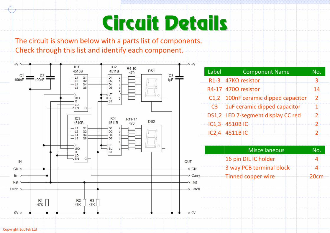
Circuit DetailsCircuit DetailsThe circuit is shown below with a parts list of components.
Check through this list and identify each component.
24511B ICIC2,4
11uF ceramic dipped capacitorC3
43 way PCB terminal block
20cmTinned copper wire
No.Miscellaneous
416 pin DIL IC holder
24510B ICIC1,3
2LED 7-segment display CC redDS1,2
2100nF ceramic dipped capacitorC1,2
14470Ω resistorR4-17
347KΩ resistorR1-3
No.Component NameLabel
Copyright EduTek Ltd
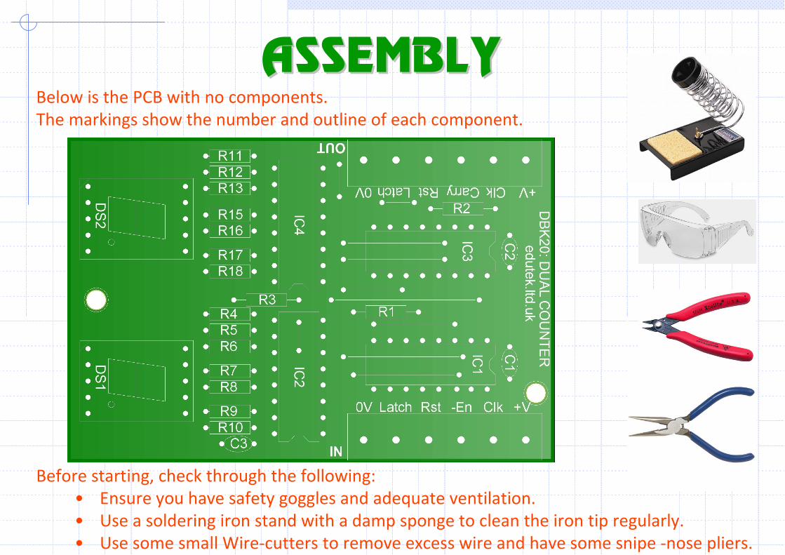
ASSEMBLYASSEMBLYBelow is the PCB with no components.
The markings show the number and outline of each component.
Before starting, check through the following:
• Ensure you have safety goggles and adequate ventilation.
• Use a soldering iron stand with a damp sponge to clean the iron tip regularly.
• Use some small Wire-cutters to remove excess wire and have some snipe -nose pliers.
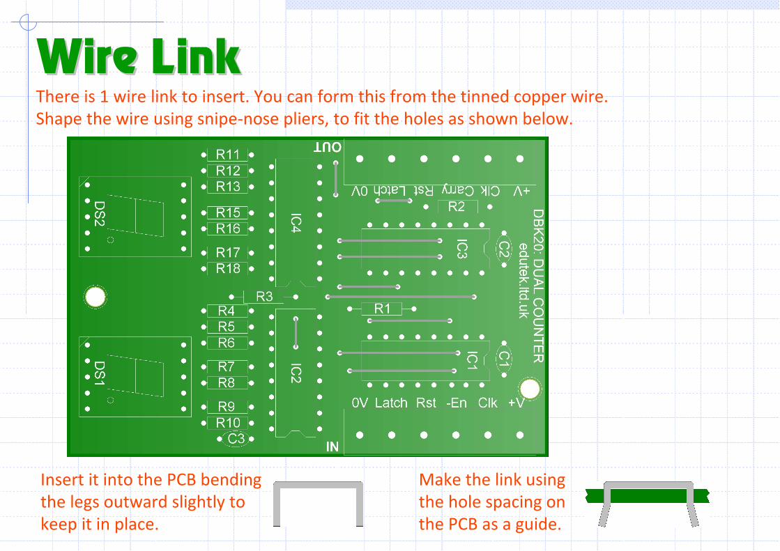
There is 1 wire link to insert. You can form this from the tinned copper wire.
Shape the wire using snipe-nose pliers, to fit the holes as shown below.
Wire LinkWire Link
Make the link using
the hole spacing on
the PCB as a guide.
Insert it into the PCB bending
the legs outward slightly to
keep it in place.
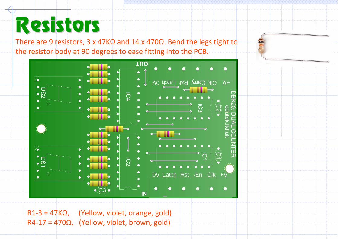
There are 9 resistors, 3 x 47KΩ and 14 x 470Ω. Bend the legs tight to
the resistor body at 90 degrees to ease fitting into the PCB.
ResistorsResistors
R1-3 = 47KΩ, (Yellow, violet, orange, gold)
R4-17 = 470Ω, (Yellow, violet, brown, gold)
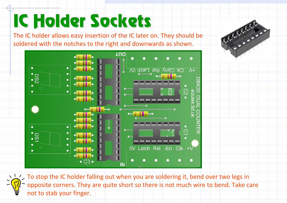
The IC holder allows easy insertion of the IC later on. They should be
soldered with the notches to the right and downwards as shown.
IC Holder SocketsIC Holder Sockets
To stop the IC holder falling out when you are soldering it, bend over two legs in
opposite corners. They are quite short so there is not much wire to bend. Take care
not to stab your finger.
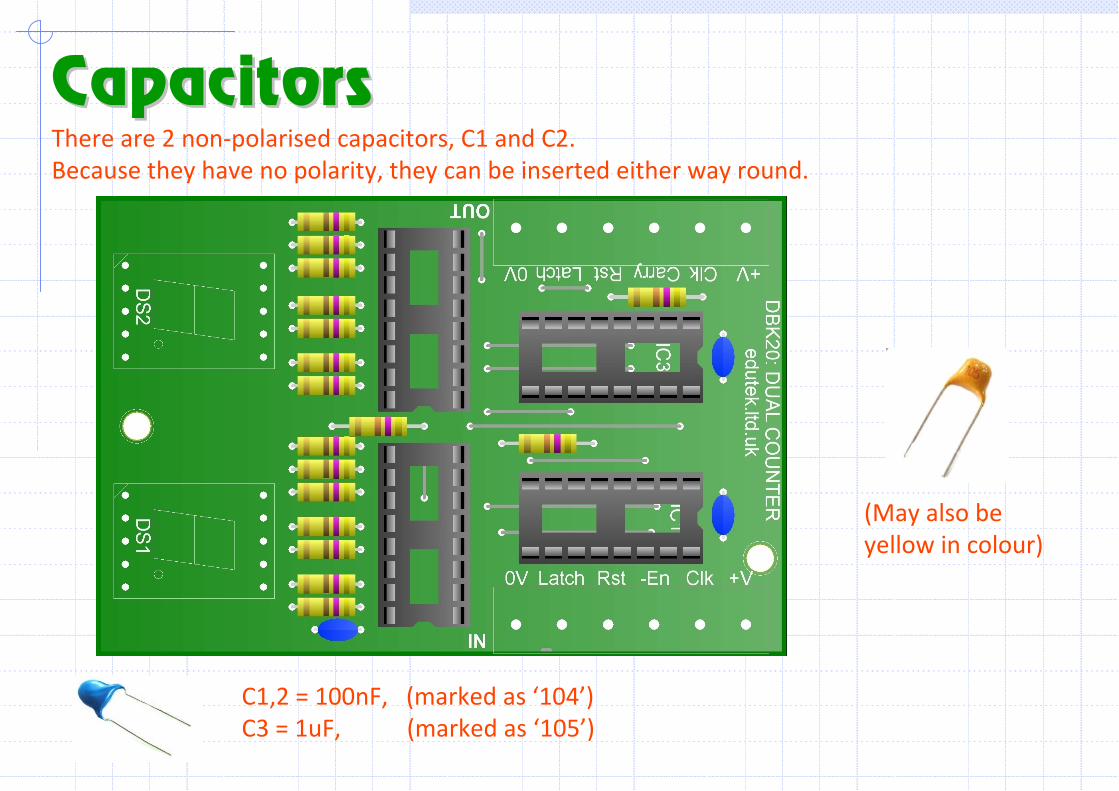
There are 2 non-polarised capacitors, C1 and C2.
Because they have no polarity, they can be inserted either way round.
CapacitorsCapacitors
C1,2 = 100nF, (marked as ‘104’)
C3 = 1uF, (marked as ‘105’)
(May also be
yellow in colour)
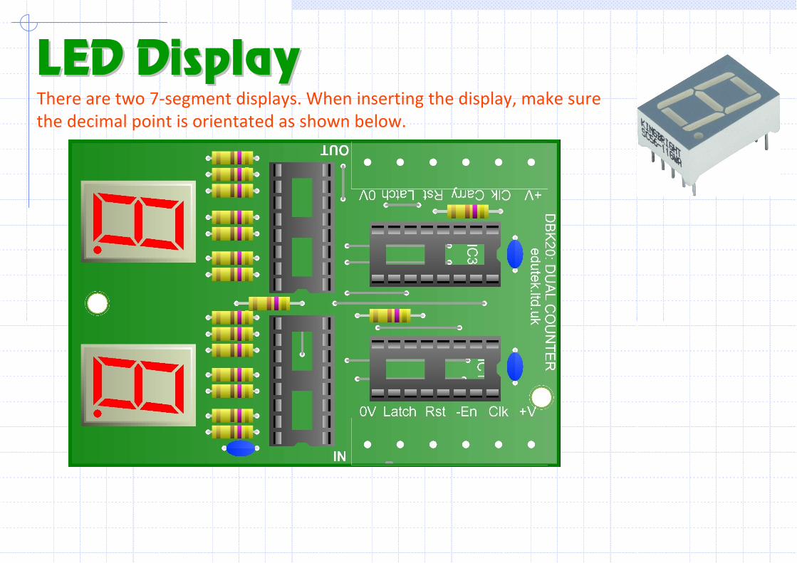
There are two 7-segment displays. When inserting the display, make sure
the decimal point is orientated as shown below.
LED DisplayLED Display
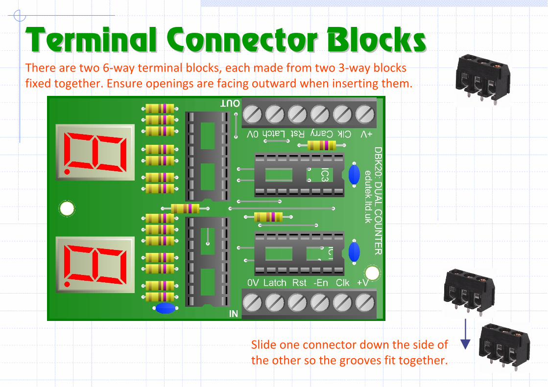
There are two 6-way terminal blocks, each made from two 3-way blocks
fixed together. Ensure openings are facing outward when inserting them.
Terminal Connector BlocksTerminal Connector Blocks
Slide one connector down the side of
the other so the grooves fit together.
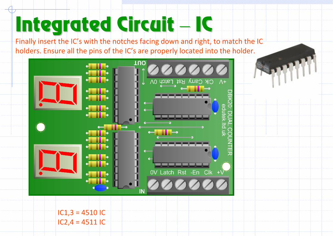
Finally insert the IC’s with the notches facing down and right, to match the IC
holders. Ensure all the pins of the IC’s are properly located into the holder.
Integrated Circuit Integrated Circuit –– IC IC
IC1,3 = 4510 IC
IC2,4 = 4511 IC