Embed Size (px)
Citation preview

PC7I N S T RU C T I O N M A N UA L
www.saftronics.com

Page i
Table of Contents
© 1999. Saftronics, Inc.
PC7 Mini VectorUser’s Manual
OverviewI. Thank You! ......................................................................... III. Safety/Hazards .................................................................. IIII. Waiver of Liability ............................................................ I IIV. Copyright .......................................................................... I IV. Introduction ...................................................................... I IVI. About This Manual .......................................................... I I IVII. If You Have Difficulty ...................................................... I I IVIII. Product Overview .......................................................... IVIX. Standard Features .......................................................... IVX. CE Marking ....................................................................... VXI. Product Specifications: 230V ........................................ VI
Product Specifications: 460V ........................................ IX
Chapter 1: Installation1.0 Receiving ...................................................................... 1-21.1 Assess the Environment .............................................. 1-31.2 Positioning ..................................................................... 1-31.3 Model Numbers ............................................................. 1-41.4 Dimensions and Weights .............................................. 1-51.5 Heat Dissipation ............................................................ 1-71.6 NEMA 4 Model Numbers ............................................... 1-71.7 NEMA 4 Dimensions ...................................................... 1-8
Chapter 2: Quickstart2.0 Pre-Power Checks ....................................................... 2-22.1 Operating the Inverter .................................................. 2-32.2 Operating the Digital Operator ..................................... 2-42.3 LED Description ............................................................ 2-7

Table of ContentsPC7 Mini Vector
User’s Manual
Page ii © 1999. Saftronics, Inc.
2.4 Monitoring ...................................................................... 2-92.5 Setting and Referencing Constants .......................... 2-112.6 Simple Data Setting ..................................................... 2-12
Chapter 3: Wiring3.0 General Precautions ..................................................... 3-33.1 Power Wiring ................................................................ 3-5
3.1.1 Power Wiring Precautions ........................................... 3-5
3.1.2 Input Protection ........................................................... 3-73.1.3 Wire Selection Recommendations .............................. 3-83.1.4 Power Interconnect Wiring .......................................... 3-93.1.5 DB Resistor Values ................................................... 3-10
3.2 Control Wiring .............................................................. 3-113.2.1 Control Wiring Precautions ........................................ 3-113.2.2 Terminal Locations ...................................................... 3-113.2.3 Control Terminal Layout ............................................ 3-123.2.4 Terminal Definitions ................................................... 3-133.2.5 Standard I/O Wiring ................................................... 3-14
3.3 Grounding ................................................................... 3-15
Chapter 4: Programming4.0 Programming ................................................................. 4-24.1 Keypad Layout .............................................................. 4-24.2 Key Functions ............................................................... 4-2
4.2.1 Display Key ................................................................. 4-3
4.2.2 Up/Down Arrows .......................................................... 4-34.2.3 Basic LED Description ................................................ 4-44.2.4 Switching Local/Remote Modes .................................. 4-54.2.5 Selecting Run/Stop Commands ................................. 4-64.2.6 Selecting Frequency Reference ................................. 4-7
4.3 First Functions ............................................................ 4-104.3.1 Constant Set-up and Initialization ............................. 4-10
4.3.2 Control Method .......................................................... 4-124.3.3 Precaution for Vector Control Application ................ 4-12
Page iii
Table of Contents
© 1999. Saftronics, Inc.
PC7 Mini VectorUser’s Manual
4.3.4 Motor Constant Calculation ...................................... 4-144.3.5 Using V/f Mode ......................................................... 4-154.3.6 When Torque is not sufficient at Low Speed ........... 4-194.3.7 Decreasing Motor Speed Fluctuation ....................... 4-194.3.8 Selecting Run/Stop Commands ............................... 4-204.3.9 Selecting Frequency by Current Reference Input .. 4-224.3.10 Selecting Stopping Method ....................................... 4-254.3.11 Setting Reverse Run Prohibit ................................... 4-264.3.12 Operator Stop Key Selection .................................... 4-264.3.13 Using Two Accel/Decel Times .................................. 4-274.3.14 Soft-Start Characteristics ......................................... 4-284.3.15 Setting Preset Speeds .............................................. 4-294.3.16 Jog Frequency Reference ....................................... 4-304.3.17 Adjusting Upper/Lower Limits ................................... 4-314.3.18 Unit Selection for Frequency Reference ................. 4-324.3.19 Motor Overload Protection ........................................ 4-334.3.20 Selecting Cooling Fan Operation .............................. 4-36
4.4 Second Functions ....................................................... 4-364.4.1 Building Interface Circuits with External Devices ... 4-364.4.2 Programming Output Terminals ................................. 4-384.4.3 Adjusting Frequency Reference Signal ................... 4-404.4.4 Using Analog Output as a Pulse Train Signal Output4-424.4.5 Using Frequency Meter or Ammeter ........................ 4-434.4.6 Calibrating Frequency Meter or Ammeter ................ 4-444.4.7 Using Multi-Function Analog Input ............................ 4-45
4.5 Third Functions ........................................................... 4-474.5.1 Carrier Frequency ..................................................... 4-47
4.5.2 Auto-Restart after Momentary Power Loss ............. 4-494.5.3 Continue Operation by Auto-Fault Reset ................. 4-494.5.4 Jump Frequencies ..................................................... 4-504.5.5 Elapsed Timer ............................................................ 4-504.5.6 Applying DC Injection Braking .................................. 4-51

Table of ContentsPC7 Mini Vector
User’s Manual
Page iv © 1999. Saftronics, Inc.
4.5.7 Stall Prevention During Decel .................................. 4-524.5.8 Preventing Motor From Stalling ................................ 4-524.5.9 Stall Prevention During Run ..................................... 4-534.5.10 Frequency Detection ................................................ 4-554.5.11 Torque Detection ....................................................... 4-574.5.12 Timing Chart Up/Down Command Input .................. 4-584.5.13 Holding Accel/Decel Temporarily ............................. 4-604.5.14 Stall Prevention During Operation ............................ 4-614.5.15 Accel/Decel Time Selection during Stall Prevention 4-62
4.6 Fourth Functions ......................................................... 4-634.6.1 Using PID Control Mode ........................................... 4-63
4.6.2 Using Energy-Saving Control Mode ......................... 4-704.6.3 Frequency Command by Pulse Train Input ............. 4-744.6.4 Using MODBUS Communications ............................ 4-75
4.6.4.1 Serial Communications Wiring ..................... 4-764.6.4.2 Procedure for Communications with PLC ... 4-77.6.4.3 Setting Parameters for Communication ........ 4-784.6.4.4 Message Format ........................................... 4-794.6.4.5 Data Read Command .................................. 4-814.6.4.6 Example of Loop-Back Test ......................... 4-824.6.4.7 Data Write Command .................................. 4-834.6.4.8 Data ............................................................... 4-84
4.6.5 Performing Self-test ................................................. 4-904.6.6 Search Operation Power Detection Hold Width ....... 4-914.6.7 Using Constant Copy Function ................................ 4-92
4.6.7.1 Constant Copy Function Selection ............. 4-934.6.7.2 Prohibiting Constant Read Selection ........... 4-934.6.7.3 Read (Upload) Function ............................... 4-944.6.7.4 Copy (Download) Function .......................... 4-954.6.7.5 Verify Function ............................................ 4-974.6.7.6 Inverter Capacity Display ........................... 4-984.6.7.7 Software Number Display ............................ 4-99
Chapter 5: PM/Troubleshooting5.0 Periodic Inspection ....................................................... 5-2

Page v
Table of Contents
© 1999. Saftronics, Inc.
PC7 Mini VectorUser’s Manual
5.1 Parts Replacement Schedule ....................................... 5-25.2 Operational Faults ......................................................... 5-25.3 Alarm and Fault Codes ................................................. 5-6
Appendix A: Parameter ListFirst Functions (n001 to n049) ................................... A-2Second Functions (n050 to n079) .............................. A-6Third Functions (n080 to n119) ................................... A-9Fourth Functions (n120 to n179) .............................. A-12
Appendix B: PID Set-upPID Set-up .....................................................................B-2
Appendix C: PC3 to PC7PC3 to PC7 Parameter Cross Reference ....................C-2
Appendix D: PID Set-upTypes of Enclosures ....................................................D-2International Electrotechnical Commission (IEC) .........D-4Cross References between NEMA Enclosures
and IEC Enclosures ..........................................D-6Enclosures for Non-Hazardous Locations .................D-7Formulas ........................................................................D-8Glossary of Terms ..................................................... D-10Conversion Factors ................................................... D-19Literature Request Form ............................................ D-20
Index
OverviewPC7 Mini VectorUser’s Manual
Page I©2000 Saftronics , Inc.
I. THANK YOU !
We at Saftronics appreciate your purchase of this PC7model adjustable frequency drive. When properlyinstalled, operated, and maintained, this unit will providea lifetime of reliable, troublefree operation.This manual was written to serve as a tool for qualifiedpersonnel to use in the installation, programming, andtroubleshooting of this equipment. It is IMPORTANT theinstaller thoroughly reads and understands theinformation contained herein before any action is taken.This document is organized via numbered chapters,which should be read in sequence before any work isperformed.
II. SAFETY/HAZARDS
!
The safety of personnel is of utmost importance toSaftronics, Inc. This symbol is used throughout thismanual to identify specific hazards which can lead topersonal injury, death, property damage or economicloss. The applicable procedures must be performedonly by qualified personnel who have been instructedwith respect to the hazards involved with potentiallylethal voltages.

Page II
Overview PC7 Mini VectorUser’s Manual
©2000 Saftronics , Inc.
III. WAIVER OF LIABILITY
IV. COPYRIGHT
V. INTRODUCTION
No patent liability is assumed with respect to the use ofthe information contained herein. Moreover, because weat Saftronics are constantly improving our high qualityproducts, the information contained in this manual issubject to change without notice. Every precaution hasbeen taken in the preparation of this manual.Nevertheless, Saftronics assumes no responsibility forerrors or omissions. Neither is any liability assumed fordamages resulting from the use of the informationcontained in this publication. In no event will Saftronicsbe responsible or liable for indirect or consequentialdamages resulting from the use or application of thisequipment.
© 2000 Saftronics, Inc. All rights reserved. Theinformation contained herein is the proprietary propertyof Saftronics, Inc., and may not be copied, reproduced ortransmitted to other parties without the expressed writtenconsent of Saftronics, Inc.
The PC7 is a high performance, microprocessor-basedAC motor speed controller. Its inherent programmingand mechanical flexibility make it the ultimate generalpurpose inverter for distributor and OEM alike. It isavailable as a protected chassis. The ultra-compactprotected chassis units are available through 10 HP at230V and through 10 HP at 460V. (see notes on productspecifications)

OverviewPC7 Mini VectorUser’s Manual
Page III©2000 Saftronics , Inc.
VI. ABOUT THIS MANUAL
VII. IF YOU HAVE DIFFICULTY
This document will serve as the installation, programmingand troubleshooting manual for the PC7 Mini Vector. Itmust be read in its entirety before any installation ortroubleshooting is performed. This manual should befollowed in sequence, starting with Chapter 1. Thechapters are organized as follows:
Chapter 1: InstallationChapter 2: QuickstartChapter 3: WiringChapter 4: ProgrammingChapter 5: PM & Troubleshooting
The PC7 adjustments are made through a family ofprogramming parameters which have a numberdesignator. By convention, this manual will print theFUNCTION numbers in bold to highlight them.
Please reread the applicable sections of this manual. Ifyou still have difficulty, contact your local distributor orauthorized representative. If they are unable to answeryour questions, please contact Saftronics technicalsupport by phone at 941-693-7200 or by fax at 941-693-2431. Before you contact the factory, make sure you havethe unit model number, serial number, program data andwiring diagram available. Your cooperation will help usserve you promptly and efficiently.

Page IV
Overview PC7 Mini VectorUser’s Manual
©2000 Saftronics , Inc.
VIII. PRODUCT OVERVIEW
IX. STANDARD FEATURES
The PC7 was designed as a compact, yet powerfulplatform to handle a wide variety of general purposeapplications. This product uses the latest inmicroprocessor technology to provide a precise, reliablecontroller for three-phase AC motors.The PC7 can be used with a single phase input, but mustalways be used with 3 phase AC motors. Consult withthe factory for special input power requirements.The PC7 has programmable I/O and will satisfy a widevariety of applications. This allows the product to suit therequirements of the user, distributor, or OEM.
þ Latest generation of power device technologyþ Compact physical sizeþ High carrier frequency (low noise) without derateþ Keypad is standardþ Single-phase operationþ Programmable I/Oþ Fan ventilated design (no cooling fans)þ Keypad for storage of programþ RS-485 communications port is standardþ DC injection braking & DB transistor are includedþ Designed to meet requirements of CEþ Meets requirements of cULþ 400 Hz maximum outputþ Comprehensive keypad displaysþ 4 fault memory (nonvolatile to retain even after power removal)þ Comprehensive ground fault protection

OverviewPC7 Mini VectorUser’s Manual
Page V©2000 Saftronics , Inc.
X. CE MARKINGThis product complies with the low voltage directive (73/23/EEC), the generic standard for industrial immunity(EN50081-2) and the CE marking directive (93/68/EEC).The PC7 also complies with the ElectromagneticCompatibility (EMC) Directive (89/336/EEC) when thefollowing requirements for a conforming installation areapplied:
þ An input RFI filter must be installed to limitconducted emissions.
þ The controller must be mounted inelectromagnetically shielded enclosure to reduceradiated emissions. A typical NEMA or IEC metalenclosure is adequate, provided there are novents and the seams are continuously welded.
þ The motor cables should be shielded cable orin metal conduit to attenuate radiated emissions.
þ Motor cable length must be kept as short aspossible.
Please Note: The conformity of the PC7 controller andany applicable filters does not necessarily guarantee thatthe entire installation will conform. Many installationspecific factors (wire routing, proper grounding, etc.) caninfluence the total installation and only directmeasurements can ensure total conformity.

Page VI
Overview PC7 Mini VectorUser’s Manual
©2000 Saftronics , Inc.
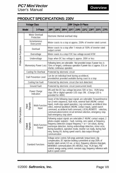
XI. PRODUCT SPECIFICATIONS: 230VssalCegatloV ssalCegatloV ssalCegatloV ssalCegatloV ssalCegatloV esahP-3/-elgniSV032 esahP-3/-elgniSV032 esahP-3/-elgniSV032 esahP-3/-elgniSV032 esahP-3/-elgniSV032
ledoM ledoM ledoM ledoM ledoMXXXX-7CP XXXX-7CP XXXX-7CP XXXX-7CP XXXX-7CP esahP-3 esahP-3 esahP-3 esahP-3 esahP-3 1P02 1P02 1P02 1P02 1P02 2P02 2P02 2P02 2P02 2P02 4P02 4P02 4P02 4P02 4P02 7P02 7P02 7P02 7P02 7P02 5P12 5P12 5P12 5P12 5P12 2P22 2P22 2P22 2P22 2P22 7P32 7P32 7P32 7P32 7P32 5P52 5P52 5P52 5P52 5P52 5P72 5P72 5P72 5P72 5P72
tuptuOrotoMelbacilppA.xaM†)PH(Wk
1.0)31.0(
2.0)52.0(
55.0)57.0(
1.1)1(
5.1)2(
2.2)3(
7.3)5(
5.5)5.7(
5.7)01(
)AVk(yticapaCretrevnI 3.0 6.0 1.1 9.1 0.3 2.4 7.6 5.9 31
)A(tnerruCtuptuOdetaR 8.0 6.1 3 5 8 11 5.71 52 33
)V(egatloVtuptuO.xaM )egatlovtupniotlanoitroporp(V032ot002,esahP-3)egatlovtupniotlanoitroporp(V042ot002,esahP-elgniS
tuptuO.xaM)zH(ycneuqerF )elbammargorp(zH004
dnaegatloVtupnIdetaRycneuqerF
zH06/05,V032ot002,esahP-3zH06/05,V042ot002,esahP-elgniS
egatloVelbawollAnoitautculF %01+ot51-
ycneuqerFelbawollAnoitautculF %5±
dohteMlortnoC )elbatceleslortnocrotcevpoolnepolortnocf/V(MWPevaWeniS
egnaRlortnoCycneuqerF zH004ot1.0
ycaruccAycneuqerF)egnahCerutarepmeT(
)C°05+ot01-(%10.0±:ecnerefeRlatigiD)C°01±52(%5.0±:ecnerefeRgolanA
gnitteSycneuqerFnoituloseR
zH1.0/)zH001nahtssel(zH10.0:ecnerefeRlatigiD )eromrozH001(ycneuqerftuptuo.xamfo0001/1:ecnerefeRgolanA
ycneuqerFtuptuOnoituloseR zH10.0
yticapaCdaolrevO etunimenoroftnerructuptuodetar%051
ecnerefeRycneuqerFlangiS
2(CDV01ot0 W0 52(Am02ot4,) W0 52(Am02ot0,) 0W eslup))elbatceles(emulovgnittesycneuqerf,tupniniart
emiTleceD/leccA .ces0006ot10.0)demmargorpyltnednepednieraemitleced/lecca(
euqroTgnikarB
‡euqrotnoitarelecedegarevamret-trohS%051:)PH52.0,PH31.0(Wk52.0,1.0
%001:)PH1,PH5.0(Wk1.1,55.0%05:)PH2(Wk5.1
%02:eromro)PH3(Wk2.2lanoitpohtiw%051(%02.xorppA:euqrotevitarenegersuounitnoC
)ni-tliubrotsisnartgnikarb,rotsisergnikarb
scitsiretcarahCf/V nrettapf/VnamargorpotelbissoP
Pow
er S
uppl
yO
utpu
tC
hara
cter
istic
sC
ontr
ol C
hara
cter
istic
s
OverviewPC7 Mini VectorUser’s Manual
Page VII©2000 Saftronics , Inc.
PRODUCT SPECIFICATIONS: 230V
ssalCegatloV ssalCegatloV ssalCegatloV ssalCegatloV ssalCegatloV esahP-3/-elgniSV032 esahP-3/-elgniSV032 esahP-3/-elgniSV032 esahP-3/-elgniSV032 esahP-3/-elgniSV032
ledoM ledoM ledoM ledoM ledoM esahP-3 esahP-3 esahP-3 esahP-3 esahP-3 1P02 1P02 1P02 1P02 1P02 2P02 2P02 2P02 2P02 2P02 4P02 4P02 4P02 4P02 4P02 7P02 7P02 7P02 7P02 7P02 5P12 5P12 5P12 5P12 5P12 2P22 2P22 2P22 2P22 2P22 7P32 7P32 7P32 7P32 7P32 5P52 5P52 5P52 5P52 5P52 5P72 5P72 5P72 5P72 5P72
daolrevOrotoMnoitcetorP yalerdaolrevolamrehtcinortcelE
suoenatnatsnItnerrucrevO tnerrucdetarretrevnifo%052.xorppatapotsaotstsaocrotoM
daolrevO detarretrevnifo%051taetunim1retfapotsaotstsaocrotoMtnerructuptuo
egatlovrevO V014deecxeegatlovsubCDfipotsaotstsaocrotoM
egatlovrednU sselroV002.xorppasiegatlovsubCDnehwspotS
ssoLrewoPyratnemoMsissolrewopfispots(dedivorptoN:elbatceleserasmetigniwolloF
ros5.0.xorppasissolrewopfinoitareposuounitnoc,)regnolrosm51noitareposuounitnoc,retrohs
taehrevOniFgnilooC tiucriccinortceleybdetcetorP
leveLnoitneverPllatS ,leced/leccagnirudlevellaudividnitesebnaCpotsaottsaocgnirudelbaliavadedivorpton/dedivorp
tluaFnaFgnilooC )noitcetedkcolnaf(tiucriccinortceleybdetcetorP
tluaFdnuorG )leveltnerrucrevo(tiucriccinortceleybdetcetorP
egrahCrewoPnoitacidnI
pmalNUR.sselroV05semocebegatlovsubCDehtlitnuNOsiDELegrahC(.NOsyatsDELrotarepolatigidroNOsyats
)V004rofdedivorp
noitcnuF-itluMtupnI
esrever/drawroF:elbatceleseraslangistupnigniwollofehtfoneveStcatnocCN/ON(tluaflanretxe,tesertluaf,)ecneuqeseriw-3(nur
emitleced/lecca,dnammocgoJ,noitarepodeepspets-itlum,)tupnihcraesdeeps,)tupnitcatnocCN/ON(kcolbesablanretxe,tceles
,dnammocdlohleced/lecca,dnammoc ETOMER/LACOL ,noitcelespotsycnegreme,noitceleslanimrettiucriclortnoc/noitacinummoc
mralapotsycnegremetluaf
noitcnuF-itluMtuptuO
2,tuptuotcatnocCN/ON1(elbatceleseraslangistuptuogniwolloF,ycneuqerfta,deepsorez,gninnur,tluaF:)stuptuorelpuoc-otohp
ycneuqerftuptuo(noitcetedycneuqerf < ro > gnirud,)eulavtes,rorreronim,noitcetedegatlovrednugnirud,noitcetedeuqrotrevotluafgnirud,ydaernurretrevni,edomnoitarepo,kcolbesabgnirud
hguorhttuptuoatad,hcraesdeepsgnirud,VUgnirud,yrternoitacinummoc
snoitcnuFdradnatS
pils,tsoobeuqrotcitamotuaegnar-lluf,lortnocrotcevegatloVfo%05(potstaemit/tnerrucgnikarbnoitcejniCD,noitasnepmoc
,niag/saibecnereferycneuqerf,)sselro.ces5.0,tnerrucdetarretrevniDIP,)spbK2.91.xam,224/584-SR(snoitacinummocSUBOMEM
htiwecnereferycneuqerf,ypoctnatsnoc,lortnocgnivas-ygrene,lortnoclortnocdeepsni-tliub
Oth
er F
unct
ions
Pro
tect
ive
Fun
ctio
ns
Out
put
Sig
nals
Inpu
tS
igna
ls

Page VIII
Overview PC7 Mini VectorUser’s Manual
©2000 Saftronics , Inc.
PRODUCT SPECIFICATIONS: 230V
** Temperature during shipping (for short period)
ssalCegatloV ssalCegatloV ssalCegatloV ssalCegatloV ssalCegatloV esahP-3/-elgniSV032 esahP-3/-elgniSV032 esahP-3/-elgniSV032 esahP-3/-elgniSV032 esahP-3/-elgniSV032
XXXX-7CPledoM XXXX-7CPledoM XXXX-7CPledoM XXXX-7CPledoM XXXX-7CPledoM esahP-3 esahP-3 esahP-3 esahP-3 esahP-3 1P02 1P02 1P02 1P02 1P02 2P02 2P02 2P02 2P02 2P02 4P02 4P02 4P02 4P02 4P02 7P02 7P02 7P02 7P02 7P02 5P12 5P12 5P12 5P12 5P12 2P22 2P22 2P22 2P22 2P22 7P32 7P32 7P32 7P32 7P32 5P52 5P52 5P52 5P52 5P52 5P72 5P72 5P72 5P72 5P72
sutatSrotacidnI
)DEL(s'DELdradnatssadedivorpMRALAdnaNUR
latigiDrotarepO
)041-POVJ(
,ycneuqerftuptuo,ecnereferycneuqerfrotinomotelbaliavAtnerructuptuo
slanimreT slanimretwercs:tiucricniaMlanimretwercsni-gulp:tiucriclortnoC
neewtebecnatsiDgniriWrotoMdnaretrevnI )sselrotf823(m001
erusolcnE detnuom-llawdesolcnerosissahcnepO
dohteMgnilooC ,)esahp-elgnis/-3(Wk57.0,V002rofdedivorpsinafgnilooCgnilooc-fleserasrehto,)esahp-3(Wk5.1,V004
erutarepmeTtneibmA05+ot01-:sissahCnepO 0 221ot41(C 0 )F
04+ot01-:detnuom-llawdesolcnE 0 501ot41(C 0 )F)nezorfton(
ytidimuH )gnisnednoc-non(sselroHR%59
**erutarepmeTegarotS 06+ot02- 0 041ot4-(C 0 )F
noitacoL )tsudrosesagevisorrocmorfeerf(roodnI
noitavelE sselro)tf0823(m0001
noitarbiV S/8.9otpU 2 ,zH02nahtsselta)G1(S/m2otpU 2 zH05ot02nahtsselta)G2.0(
Oth
er F
unct
ions
Envi
ronm
enta
l Con
ditio
ns
Dis
play

OverviewPC7 Mini VectorUser’s Manual
Page IX©2000 Saftronics , Inc.
PRODUCT SPECIFICATIONS: 460V
ssalCegatloV ssalCegatloV ssalCegatloV ssalCegatloV ssalCegatloV esahP-3V064 esahP-3V064 esahP-3V064 esahP-3V064 esahP-3V064
XXXX-7CPledoM XXXX-7CPledoM XXXX-7CPledoM XXXX-7CPledoM XXXX-7CPledoM esahP-3 esahP-3 esahP-3 esahP-3 esahP-3 2P04 2P04 2P04 2P04 2P04 4P04 4P04 4P04 4P04 4P04 7P04 7P04 7P04 7P04 7P04 5P14 5P14 5P14 5P14 5P14 2P24 2P24 2P24 2P24 2P24 7P34 7P34 7P34 7P34 7P34 5P54 5P54 5P54 5P54 5P54 5P74 5P74 5P74 5P74 5P74
tuptuOrotoMelbacilppA.xaM)PH(Wk
73.0)5.0(
55.0)1/57.0(
1.1)2/5.1(
5.1)3(
2.2)3(
7.3)5(
5.5)5.7(
5.7)01(
)AVk(yticapaCretrevnI 9.0 4.1 6.2 7.3 2.4 0.7 11 41
)A(tnerruCtuptuOdetaR 2.1 8.1 4.3 8.4 5.5 2.9 8.41 81
)V(egatloVtuptuO.xaM )egatlovtupniotlanoitroporp(V064ot083,esahp-3
ycneuqerFtuptuO.xaM)zH( )elbammargorp(zH004
egatloVtupnIdetaRycneuqerFdna zH06/05,V064ot083,esahp-3
egatloVelbawollAnoitautculF %01+ot51-
ycneuqerFelbawollAnoitautculF %5±
dohteMlortnoC )elbatceleslortnocegatlov/lortnocf/V(MWPevaweniS
egnaRlortnoCycneuqerF zH004ot1.0
ycaruccAycneuqerF)egnahCerutarepmeT(
)F°221ot41(C°05+ot01-,%10.0±:ecnereferlatigiD)F°59ot95(C°01±52,%5.0±:ecnerefergolanA
gnitteSycneuqerFnoituloseR
zH1.0/)zH001nahtssel(zH10.0:ecnereferlatigiD)eromrozH001(
ycneuqerftuptuo.xamfo0001/1:ecnerefergolanA
ycneuqerFtuptuOnoituloseR zH10.0
yticapaCdaolrevO etunimenoroftnerructuptuodetar%051
ecnerefeRycneuqerFlangiS
02(CDV01ot0 kW 02ot4,) 052(Am W ,) 052(Am02ot0 W))elbatceles(emulovgnittesycneuqerf,tupniniarteslup
emiTleceD/leccA yltnednepednieraemitleced/lecca(.ces0006ot10.0)demmargorp
euqroTgnikarB
‡euqrotnoitrelecedegarevamret-trohS%051:Wk2.0%001:Wk57.0
%05:)PH2(Wk5.1%02:eromro)PH3(Wk2.2
htiw%051(%02.xorppA:euqrotevitarenegersuounitnoC)ni-tliubrotsisnartgnikarb,rotsisergnikarblanoitpo
scitsiretcarahCf/V nrettapf/VynamargorpotelbissoP
Pow
er S
uppl
yO
utpu
tC
hara
cter
istic
sC
ontr
ol C
hara
cter
istic
s

Page X
Overview PC7 Mini VectorUser’s Manual
©2000 Saftronics , Inc.
egatloV egatloV egatloV egatloV egatloV esahP-3V064 esahP-3V064 esahP-3V064 esahP-3V064 esahP-3V064
XXXX-7CPledoM XXXX-7CPledoM XXXX-7CPledoM XXXX-7CPledoM XXXX-7CPledoM esahP-3 esahP-3 esahP-3 esahP-3 esahP-3 2P04 2P04 2P04 2P04 2P04 4P04 4P04 4P04 4P04 4P04 7P04 7P04 7P04 7P04 7P04 5P14 5P14 5P14 5P14 5P14 2P24 2P24 2P24 2P24 2P24 7P34 7P34 7P34 7P34 7P34 5P54 5P54 5P54 5P54 5P54 5P74 5P74 5P74 5P74 5P74
daolrevOrotoMnoitcetorP
yalerdaolrevolamrehtcinortcelE
suoenatnatsnItnerrucrevO
detarretrevnifo%052.xorppatapotsaotstsaocrotoMtnerruc
daolrevO retrevnifo%051taetunim1retfapotsaotstsaocrotoMtnerructuptuodetar
egatlovrevO V028deecxeegatlovsubCDfipotsaotstsaocrotoM
egatlovrednU sselroV004.xorppasiegatlovsubCDnehwspotS
ssoLrewoPyratnemoM
fispots(dedivorptoN:elbatceleserasmetigniwolloFfinoitareposuounitnoc,)regnolrosm51sissolrewop
suounitnoc,retrohsros5.0.xorppasissolrewopnoitarepo
taehrevOniFgnilooC tiucriccinortceleybdetcetorP
leveLnoitneverPllatS ,leced/leccagnirudslevellaudividniottesebnaCpotsaottsaocgnirudelbaliavadedivorpton/dedivorp
tluaFnaFgnilooC )noitcetedkoolnaf(tiucriccinortceleybdetcetorP
tluaFdnuorG )leveltnerrucrevo(tiucriccinortceleybdetcetorP
noitacidnIegrahCrewoPnuR.sselroV05semocebegatlovsubCDehtlitnuNO
.NOsyatsDELrotarepolatigidroNOsyaspmal)V004rofdedivorpsiDELegrahC(
noitcnuF-itluMtupnI
:elbatceleseraslangistupnigniwollofehtfoneveS,tesertluaf,)ecneuqeseriw-3(nuresreveR/drawroF
deepspets-itlum,)tupnitcatnocCN/ON(tluaflanretxelanretxe,tcelesemitleced/lecca,dnammocgoJ,noitarepo,dnammochcraesdeeps,)tupnitcatnocCN/ON(kcolbesab
,noitcelesETOMER/LACOL,dnammocdlohleced/lecca,noitceleslanimrettiucriclortnoc/noitacinummoc
mralapotsycnegremetluafpotsycnegreme
noitcnuF-itluMtuptuO
tcatnocCN/ON1(elbatceleseraslangistuptuogniwolloForez,gninnur,tluaF:)stuptuorelpuoc-otohp2,tuptuo
tuptuo(noitcetedycneuqerf,ycneuqerfta,deepsycneuqerf < ro > ,noitcetedeuqrotrevognirud,)eulavtes
gnirud,rorreronim,noitcetedegatlovrednugnirudgnirud,ydaernurretrevni,edomnoitarepo,kcolbesab
tuptuoatad,hcraesdeepsgnirud,VUgnirud,yrtertluafnoitacinummochguorht
snoitcnuFdradnatS
,tsoobeuqrotcitamotuaegnar-lluf,lortnocrotcevegatloVtaemit/tnerrucgnikarbnoitcejniCD,noitasnepmocpils
,)sselro.ces5.0,tnerrucdetarretrevnifo%05(potsSUBOMEM,niag/saibecnereferycneuqerf
DIP)spbK2.91.xam,224/584-SR(snoitacinummocycneuqerf,ypoctnatsnoc,lortnocgnivas-ygrene,lortnoc
lortnocdeepsni-tliubhtiwecnerefer
PRODUCT SPECIFICATIONS: 460V
Pro
tect
ive
Fun
ctio
ns
Out
put
Sig
nals
Inpu
tS
igna
ls
Oth
er F
unct
ions

OverviewPC7 Mini VectorUser’s Manual
Page XI©2000 Saftronics , Inc.
PRODUCT SPECIFICATIONS: 460V
ssalCegatloV ssalCegatloV ssalCegatloV ssalCegatloV ssalCegatloV esahP-3V064 esahP-3V064 esahP-3V064 esahP-3V064 esahP-3V064
XXXX-7CPledoM XXXX-7CPledoM XXXX-7CPledoM XXXX-7CPledoM XXXX-7CPledoM esahP-3 esahP-3 esahP-3 esahP-3 esahP-3 2P04 2P04 2P04 2P04 2P04 4P04 4P04 4P04 4P04 4P04 7P04 7P04 7P04 7P04 7P04 5P14 5P14 5P14 5P14 5P14 2P24 2P24 2P24 2P24 2P24 7P34 7P34 7P34 7P34 7P34 5P54 5P54 5P54 5P54 5P54 5P74 5P74 5P74 5P74 5P74
sutatSrotacidnI
)DEL(s'DELdradnatssadedivorpMRALAdnaNUR
latigiDrotarepO
)041-POVJ(
tuptuo,ecnereferycneuqerfrotinomotelbaliavAtnerructuptuo,ycneuqerf
slanimreT slanimretwercs:tiucricniaMlanimretwercsni-gulp:tiucriclortnoC
ecnatsiDgniriWdnaretrevnIneewteb
rotoM)sselrotf823(m001
erusolcnE detnuom-llawdesolcnerosissahcnepO
dohteMgnilooC -elgnis/-3(Wk57.0,V002rofdedivorpsinafgnilooCgnilooc-fleserasrehto,)PH5.1(Wk57.0,V002,)esahp
erutarepmeTtneibmA05+ot01-:sissahcnepO 0 221ot41(C 0 )F
)°501+ot41-(C°04+ot01-:detnuomllawdesolcnE)nezorfton(
ytidimuH )gnisnednoc-non(sselroHR%59
**erutarepmeTegarotS 06+ot02- 0 041ot4-(C 0 )F
noitacoL )tsudrosesagevisorrocmorfeerf(roodnI
noitavelE sselro)tf0823(m0001
noitarbiV S/m8.9otpU 2 zH02nahtsselta)G1(S/m2otpU 2 zH05ot02nahtsselta)G2.0(
Oth
er F
unct
ions
Envi
ronm
enta
l Con
ditio
ns
Dis
play
** Temperature during shipping (for short period)

Page XII
Overview PC7 Mini VectorUser’s Manual
©2000 Saftronics , Inc.
This page intentionally left blank.

Page 1-1
Chapter 1: InstallationPC7 Mini VectorUser’s Manual
©2000 Saftronics , Inc.
Chapter 1:
Installation
What this chapter tells you:1) How to properly receive the PC7.2) How to assess the installation environment.3) How to properly mount the PC7.4) The unit dimensions and heat dissipation.

Page 1-2
Chapter 1: Installation PC7 Mini VectorUser’s Manual
©2000 Saftronics , Inc.
You must confirm the model number and outputcurrent (HP) rating of the inverter before you applypower. Application of the wrong power supply cancause unit damage.
!
1.0 RECEIVING
The PC7 has been subjected to demanding tests prior toshipment from Saftronics’ factory. To ensure properoperation and life of the equipment you must verify themodel number is proper for the application. Please dothe following before applying power:
þ Inspect the shipping container. If damaged,you should immediately notify both Saftronics andthe carrier and file a claim with the carrier within14 days of receipt of the unit.
þ Verify that the model number on the box (and theinverter) matches the invoice and the originalpurchase order.
þ If you find any discrepancy, please notify eitheryour distributor or authorized Saftronics agentimmediately so corrective action can beimplemented.

Page 1-3
Chapter 1: InstallationPC7 Mini VectorUser’s Manual
©2000 Saftronics , Inc.
1.1 ASSESS THE ENVIRONMENTThe selection of the proper mounting location of the PC7is imperative to achieve maximum operating performanceand reliability. These units were designed to withstandthe harsh demands of industrial installations.Nevertheless, caution should be exercised to ensure thechosen environment meets the following:
þ Ambient temperature: 14 to 1220F (-10 to +500 )þ Protect from rain or moistureþ Protect from corrosive gases or liquidsþ Shelter from direct sunlightþ Free from excessive mechanical vibrationþ Free from radioactivityþ Free from oil sprays or splashesþ Relative humidity: 95% maximum,
non-condensingþ Protect from salt sprayþ Protect from dust or metallic particles in the airþ Protect from magnetic noise: welding
machines, power devices, etc.þ Combustibles: thinner, solvents, etc.
1.2 POSITIONINGMake sure there is a minimum clearance of 1.18” (30mm) around the sides of the PC7 unit and at least 4inches above and below it to provide effective coolingand to meet NEC wiring requirements. The unit shouldbe installed on a flat, vertical and level surface with theheatsink ribs oriented vertically.

Page 1-4
Chapter 1: Installation PC7 Mini VectorUser’s Manual
©2000 Saftronics , Inc.
1.3 MODEL NUMBERSThe PC7 is available as a protected chassis unit.The table below gives the various model numbers.
PC7 Mini Vector Model Numbers
egatloVtupnIrebmuNledoM
esahP-3PH
)Wk(tuptuOdetaR
tnerruC
esahP-3V032-V002
1P027CP 31.0)10.( 8.0
2P027CP 52.0)2.0( 6.1
4P027CP 57.0/05.0)4.0( 3
7P027CP 0.1)57.0( 5
5P127CP 0.2)5.1( 8
2P227CP 0.3)2.2( 11
7P327CP 0.5)7.3( 5.71
5P527CP 5.7)5.5( 52
5P727CP 01)5.7( 33
esahP-3V064-V083
2P047CP 05.0)2.0( 2.1
4P047CP 0.1/57.0)4.0( 8.1
7P047CP 0.2/5.1)57.0( 4.3
5P147CP 0.3)5.1( 8.4
2P247CP 0.3)2.2( 5.5
7P347CP 0.5)7.3( 2.9
5P547CP 5.7)5.5( 8.41
5P747CP 01)5.7( 81

Page 1-5
Chapter 1: InstallationPC7 Mini VectorUser’s Manual
©2000 Saftronics , Inc.
1.4 DIMENSIONS AND WEIGHTSThe PC7 is available as a NEMA 1 unit, the table gives thedimensions in inches (mm), mass in lbs (kg) and heatloss (W). (For single-phase information consultfactory.
PC7 Mini Vector Dimensions
egatloV egatloV egatloV egatloV egatloVssalC ssalC ssalC ssalC ssalC
yticapaC yticapaC yticapaC yticapaC yticapaC)Wk(PH )Wk(PH )Wk(PH )Wk(PH )Wk(PH
)mm(sehcnIsnoisnemiDllarevO )mm(sehcnIsnoisnemiDllarevO )mm(sehcnIsnoisnemiDllarevO )mm(sehcnIsnoisnemiDllarevO )mm(sehcnIsnoisnemiDllarevO ssaM ssaM ssaM ssaM ssaMbLbLbLbLbL
)gk( )gk( )gk( )gk( )gk(
)W(ssoLtaeH )W(ssoLtaeH )W(ssoLtaeH )W(ssoLtaeH )W(ssoLtaeH.giF .giF .giF .giF .giF
WWWWW HHHHH DDDDD 1W1W1W1W1W 1H1H1H1H1H 2H2H2H2H2H 3H3H3H3H3H 4H4H4H4H4H ddddd-taeH -taeH -taeH -taeH -taeH
knis knis knis knis knis tinU tinU tinU tinU tinU latoT latoT latoT latoT latoT
V032esahP-3
31.0)1.0(
86.2)86(
38.5)841(
99.2)67(
02.2)65(
56.4)811(
02.0)5(
40.5)821(
97.0)02( 4M 55.1
)7.0( 7.3 3.9 31 1
52.0)2.0(
86.2)86(
38.5)841(
99.2)67(
02.2)65(
56.4)811(
02.0)5(
40.5)821(
97.0)02( 4M 55.1
)7.0( 7.7 3.01 81 1
05.0)4.0(
86.2)86(
38.5)841(
52.4)801(
02.2)65(
56.4)811(
02.0)5(
40.5)821(
97.0)02( 4M 02.2
)0.1( 8.51 3.21 1.82 1
0.1)57.0(
52.4)801(
38.5)841(
40.5)041(
02.2)65(
56.4)811(
02.0)5(
40.5)821(
97.0)02( 4M 56.2
)2.1( 4.82 7.61 1.54 1
0.2)5.1(
52.4)801(
38.5)841(
61.5)131(
87.3)69(
56.4)811(
02.0)5(
40.5)821(
97.0)02( 4M 35.3
)6.1( 7.35 1.91 8.27 2
0.3)2.2(
52.4)801(
38.5)841(
15.5)041(
87.3)69(
56.4)811(
02.0)5(
40.5)821(
97.0)02( 4M 57.3
)7.1( 4.06 4.43 8.49 2
0.5)7.3(
15.5)041(
38.5)841(
36.5)341(
40.5)821(
56.4)811(
02.0)5(
40.5)821(
97.0)02( 4M 03.5
)4.2( 7.69 4.25 1.941 2
*5.7)5.5(
90.7)081(
42.01)062(
96.6)071(
64.6)461(
16.9)442(
13.0)8(
42.01)062 0 4M 31.01
)6.4( 4.071 4.97 8.942 2
*01)5.7(
90.7)081(
42.01)062(
96.6)071(
64.6)461(
16.9)442(
13.0)8(
42.01)062 0 5M 75.01
)8.4( 2.912 6.89 1.813 2
V064esahP-3
05.0)2.0(
52.4)801(
38.5)841(
26.3)29(
87.3)69(
56.4)811(
02.0)5(
40.5)821(
97.0)02( 4M 56.2
)2.1( 4.9 7.31 1.32 2
57.0)4.0(
52.4)801(
38.5)841(
34.4)011(
87.3)69(
56.4)811(
02.0)5(
40.5)821(
97.0)02( 4M 56.2
)2.1( 1.51 0.51 1.03 2
2/5.1)57.0(
52.4)801(
38.5)841(
15.5)041(
87.3)69(
56.4)811(
02.0)5(
40.5)821(
97.0)02( 4M 57.3
)7.1( 3.03 6.42 9.45 2
0.3)5.1(
52.4)801(
38.5)841(
41.6)651(
87.3)69(
56.4)811(
02.0)5(
40.5)821(
97.0)02( 4M 57.3
)7.1( 8.54 9.92 7.57 2
0.3)2.2(
52.4)801(
38.5)841
41.6)651(
87.3)69(
56.4)811(
02.0)5(
40.5)821(
97.0)02( 4M 57.3
)7.1( 5.05 5.23 38 2
0.5)7.3(
15.5)041(
38.5)841(
36.5)341(
40.5)821(
56.4)811(
02.0)5(
40.5)821(
97.0)02( 4M 03.5
)4.2( 4.37 5.44 9.711 2
*5.7)5.5(
90.7)081(
42.01)062(
96.6)071(
64.6)461(
16.9)442(
13.0)8(
42.01)062 0 5M 75.01
)8.4( 8.861 7.78 5.652 2
*01)5.7(
90.7)081(
42.01)062
96.6)071(
64.6)461(
16.9)442(
13.0)8(
42.01)062( 0 5M 75.01
)8.4( 6.902 3.99 9.803 2
*200/400V class, 7.5/10 HP (5.5/7.5 kW) inverters can be used as “IPOO” if the top and bottomcovers are removed.

Page 1-6
Chapter 1: Installation PC7 Mini VectorUser’s Manual
©2000 Saftronics , Inc.
D0.33(8.5)
H1 H3
W
W1
2-d
H2
D0.33 (8.5)
H1 H3
WW1
4-d
H
H4
0.06
(1.5
)
H
0.06
(1.5
)
Fig. 2
Fig. 1

Page 1-7
Chapter 1: InstallationPC7 Mini VectorUser’s Manual
©2000 Saftronics , Inc.
1.5 HEAT DISSIPATIONThe wattage figures given in the table above should beused for evaluating enclosure size for non-ventilatedNEMA 12 and NEMA 4 enclosures.
1.6 NEMA 4 MODEL NUMBERSThe PC7 is available as a Nema 4 unit. The table belowgives the NEMA 4 model numbers.
PC7 NEMA 4 Mini Vector Model Numbers
egatloVtupnI egatloVtupnI egatloVtupnI egatloVtupnI egatloVtupnIrebmuNledoM rebmuNledoM rebmuNledoM rebmuNledoM rebmuNledoM
esahP-3 esahP-3 esahP-3 esahP-3 esahP-3PO/w4AMEN PO/w4AMEN PO/w4AMEN PO/w4AMEN PO/w4AMEN
rebmuNledoM rebmuNledoM rebmuNledoM rebmuNledoM rebmuNledoMesahP-3 esahP-3 esahP-3 esahP-3 esahP-3
o/w4AMEN o/w4AMEN o/w4AMEN o/w4AMEN o/w4AMENPOPOPOPOPO
)Wk(PH )Wk(PH )Wk(PH )Wk(PH )Wk(PH tuptuOdetaR tuptuOdetaR tuptuOdetaR tuptuOdetaR tuptuOdetaRtnerruC tnerruC tnerruC tnerruC tnerruC
esahP-3 esahP-3 esahP-3 esahP-3 esahP-3V032-002 V032-002 V032-002 V032-002 V032-002
41P027CP B41P027CP )10.(31.0 8.0
42P027CP B42P027CP )2.0(52.0 6.1
44P027CP B44P027CP )4.0(57.0/05.0 3
47P027CP B47P027CP )57.0(0.1 5
esahP-3 esahP-3 esahP-3 esahP-3 esahP-3V064-V083 V064-V083 V064-V083 V064-V083 V064-V083
42P047CP B42P047CP )2.0(05.0 2.1
44P047CP B44P047CP )4.0(0.1/57.0 8.1
47P047CP B47P047CP )57.0(0.2/5.1 4.3
NOTE: You must supply liquid-tight conduit to comply with NEC codes and local applicablecodes for a NEMA 4 enclosure. The NEC code states that the properly sized terminal fittingsmust be utilized in the connection between the conduit and the NEMA 4 enclosure to insure theNEMA 4 integrity of the system.

Page 1-8
Chapter 1: Installation PC7 Mini VectorUser’s Manual
©2000 Saftronics , Inc.
1.7 NEMA 4 DIMENSIONSThe PC7 is available as a NEMA 4 unit, the table belowgives the overall dimensions.
PC7 NEMA 4 Mini Vector Dimensions
egatloV egatloV egatloV egatloV egatloVssalC ssalC ssalC ssalC ssalC
yticapaC yticapaC yticapaC yticapaC yticapaC)Wk(PH )Wk(PH )Wk(PH )Wk(PH )Wk(PH
snoisnemiDllarevO snoisnemiDllarevO snoisnemiDllarevO snoisnemiDllarevO snoisnemiDllarevO)mm(sehcnI )mm(sehcnI )mm(sehcnI )mm(sehcnI )mm(sehcnI erugiF erugiF erugiF erugiF erugiF
thgieH thgieH thgieH thgieH thgieH htdiW htdiW htdiW htdiW htdiW *htpeD *htpeD *htpeD *htpeD *htpeD
V032 V032 V032 V032 V032esahP-3 esahP-3 esahP-3 esahP-3 esahP-3
)1.0(31.0 )742(47.9 )191(5.7 )931(84.5 3)2.0(52.0 )742(47.9 )191(5.7 )931(84.5 3)4.0(05.0 )742(47.9 )191(5.7 )931(84.5 3)57.0(0.1 )742(47.9 )191(5.7 )931(84.5 3
V064 V064 V064 V064 V064esahP-3 esahP-3 esahP-3 esahP-3 esahP-3
)2.0(05.0 )742(47.9 )191(5.7 )931(84.5 3)4.0(57.0 )742(47.9 )191(5.7 )931(84.5 3
)57.0(2/5.1 )742(47.9 )191(5.7 )931(84.5 3
*Add .71” (18 mm) for NEMA 4 with speed pot
D
D w/OP
H
W
Fig. 3

Chapter 2: Quickstart
Page 2-1
PC7 Mini VectorUser’s Manual
©2000 Saftronics , Inc.
Chapter 2:
Quickstart
What this chapter tells you:1) The features of the digital operator.2) The functions of the digital operator.3) The monitoring constants of the PC7.4) Simple data setting of the PC7.

Chapter 2: Quickstart
Page 2-2
PC7 Mini VectorUser’s Manual
©2000 Saftronics , Inc.
!Only qualified personnel should attempt start-up of this equipment. Improper operationcould present a hazard to personnel safety orto the driven equipment. This manual mustbe read and understood in its entirety beforeany changes are made to the programmingparameters. Potentially lethal voltages arepresent in and around this equipment andextreme caution must be exercised at all times.
2.0 PRE-POWER CHECKSYou must first inspect the installation to make sure theinverter is mounted and wired in accordance withChapters 1 & 2 of this manual. Take special care to lookfor the following:
þ Make sure power is off (the red charged LED onthe unit must also be off).
þ Check to make sure wiring is secure and allscrew terminals are tight.
þ Make sure there is no loose debris in or aroundthe inverter (closely check for metal filings).
þ If possible, make sure the motor is uncoupledfrom the load. If this isn’t possible, make sure theequipment is ready for rotation and be preparedto verify the direction of rotation.
þ Measure the input voltage and make sure it iswithin the inverter’s specifications.
þ Verify the proper direction of motor rotation. Thiscan easily be done by using the Run key on thekeypad and apply a FREF to the drive.

Chapter 2: Quickstart
Page 2-3
PC7 Mini VectorUser’s Manual
©2000 Saftronics , Inc.
You must confirm the model number and outputcurrent (HP) rating of the inverter before you applypower. Application of the wrong power supplycan cause unit damage.
!
2.1 OPERATING THE INVERTER
Initially set the control mode parameter (n002) to the V/fmode.
Test Run
The inverter will not operate until the frequency reference(speed) is set. There are three types of run commandmodes for the PC7:
1. Run command from the digital operator(volume/digital setting).
2. Run command from the control circuit terminal.
3. Run command from communications(MODBUS communications).
Prior to shipping, the drive is set up to receive runcommand and frequency reference from the terminals.Table on page 2-5 has instructions for running the PC7using the digital operator. For instructions on operation,refer to pages 2-5 and 2-11.

Chapter 2: Quickstart
Page 2-4
PC7 Mini VectorUser’s Manual
©2000 Saftronics , Inc.
2.2 OPERATING THE DIGITAL OPERATOR
All functions of the PC7 are set by the digital operator.Below are descriptions of the display and keypadsections.
FERFecnereferycneuqerF
gnirotinom/gnittes( NEERG )
TUOFycneuqerftuptuO
rotinom)NEERG(
TUOItnerructuptuO
rotinom)NEERG(
RTNMnoitcnuf-itluM
rotinom)NEERG(
R/FNURrotarepO
VER/DWFdnammocnoitceles)NEERG(
ER/OLETOMER/LACOL
noitceleS)DER(
MGRPatad/.ontnatsnoC
)DER(
Digital Operator: JVOP-140
Press to enter theconstant data.(Display the constantdata when selectingconstant no. byPRGM LED.)
Data display section
Press to switchbetweenfunctions LED’s
Press to increaseconstant no./datavalue.
Press to decreaseconstant no./datavalue.
Status indicator(same function withRUN indicator)
Press to stop the motor.(Press to reset at faults.)
Press to runthe motor.
Frequencysetting control(potentiometer)Changes frequencysetting according toposition.
Function display LED’sLED switches to anotherfunction each timeDSPL is pressed.The displayed datacan be changed. FREF
F/R
FOUT IOUT
LO/RE
MNTR
PRGM
DSPL
DATA
RUN
STOPRESET
DigitalOperatorJVOP-140
ENTER

Chapter 2: Quickstart
Page 2-5
PC7 Mini VectorUser’s Manual
©2000 Saftronics , Inc.
spetSnoitarepOrotarepO
yalpsiDDEL-21yalpsiD
sutatSrotacidnI
DEL
.NOrewopehtnruT.1 00.0 NURMRALA
.tfelehtotylluflortnocdeepsehtnruT.2 00.0 NURMRALA
.syekgnisunurVER/DWFtceleS.sknilbR/F.3 ROFroVER
NURMRALA
sinuresrevernehwVERtcelesreveN.detibihorp
.NURsserpnehT.FERFknilbotLPSDsserP.4 00.0 NURMRALA
lortnocdeepsehtgninrutybrotomehtsetarepO.5sdnopserrocecnereferycneuqerf(.thgirehtot
).deyalpsidsinoitisoplortnocdeepsehtot
ot00.000.06
muminiMtuptuo
ycneuqerfzH05.1si
NURMRALA
,yldipardehctiwssilortnocdeepsehtfIrosetareleccaoslarotomehtehtotgnidnopserrocyldiparsetarelecednoitnettayaP.tnemevomlortnocdeepshtiwemulovehthctiwsdnasutatsdaolot.tnemevomrotomtceffaottondeepseht
PC7 Digital Operator
NOTE:
NOTE:
FREF
FREF
F/R
FREF
FREF
þ Motor rotates smoothlyþ Motor rotates in the correct directionþ Motor does not have abnormal vibration or noiseþ Acceleration or deceleration is smoothþ Current matching the load flowsþ Status indicator LED’s and digital operator display
are correct
Operation Check Points
Status Indicator Lamp : Blinking: ON : OFF

Chapter 2: Quickstart
Page 2-6
PC7 Mini VectorUser’s Manual
©2000 Saftronics , Inc.
Description of Status Indicator LED’s
There are two LED’s on the middle right section of theface of the PC7. The inverter status is indicated by variouscombinations of ON, BLINKING, and OFF LED’s. RUNindicator and status indicator on the RUN button have thesame function.
For details on how the status indicator LED’s functionat inverter faults, refer to Chapter 5 “PM andTROUBLESHOOTING” on page 5-6. If a fault occurs, theALARM LED lights.
The fault can be reset by turning ON the fault reset signal(or pressing key on the digital operator) with theoperation signal OFF or by turning OFF the power supply.If the operation signal is ON, the fault cannot be reset bythe fault reset signal.
NOTE:
STOPRESET
Operation Ready(during stop)(Green)
(Red)RUN
ALARM
ON Blinking (Long Blinking) Blinking OFF
NormalOperation

Chapter 2: Quickstart
Page 2-7
PC7 Mini VectorUser’s Manual
©2000 Saftronics , Inc.
FORFORFORFORFOR (forward run) RRRRREEEEEV V V V V (reverse run)
2.3 LED DESCRIPTION
FREF
By pressing DSPL on the digital operator, each of thefunction LED’s can be selected.
The following flowchart describes each function LED.
Power ON
Frequency referencesetting/monitor (Hz)Sets PC7 operation speed.
Output frequency monitor (Hz)Displays frequency that PC7is currently outputting.Setting disabled.
Output current monitor (A)Displays current that PC7is currently outputting.Setting disabled.
Multi-function monitorDescription of the selectedmonitor is displayed.(see pg. 2-8 and 2-9)
FWD/REV run selectionSets the motor rotation directionwhen run command is given bythe digital operator.
DSPL
DSPL
DSPL
DSPL
FOUT
IOUT
MNTR
F/R
DSPL
If the PC7 losespower while in one ofthese modes, it willreturn to this modeonce power isrestored.
Monitor No.U-01: Frequency
reference (FREF)U-02: Output frequency (FOUT)U-03: Output current (IOUT)U-04: Output voltage reference
(Unit: 1V)U-05: DC bus voltage (Unit: 1V)U-06: Input terminal statusU-07: Output terminal statusU-08: Torque monitorU-09: Fault HistoryU-10: Software No.U-11: Output powerU-15: Data reception errorU-16: PID feedbackU-17: PID outputU-18: PID output
fg

Chapter 2: Quickstart
Page 2-8
PC7 Mini VectorUser’s Manual
©2000 Saftronics , Inc.
DSPL
DSPL
LO/RE
PRGM
LLLLLooooo (Local) rrrrrEEEEE (Remote)
LOCAL/REMOTE SelectionThis function switches the operation: operation usingthe digital operator including frequency setting withvolume, or that using the input terminals or throughcommunications.
Constant No./DataSets and changes data using constant No.(Refer to page 4-15).
F/R
Return to
Multi-Function Monitor
Selecting monitorPress key. When is ON, datacan be displayed by selecting monitor constant no.
Example: Monitoring Output Voltage Reference
DSPL
MNTR
FREF
MNTR
or
IOUT
DSPL
MNTRU - 0 4
DSPL2 0 0
MNTRENTER
Output voltage referenceis displayed.
ENTERSelect U-04 bypressing or key.<<
DSPL
fg

Chapter 2: Quickstart
Page 2-9
PC7 Mini VectorUser’s Manual
©2000 Saftronics , Inc.
2.4 MONITORING
Following items can be monitored by U-constants.
tnatsnoC tnatsnoC tnatsnoC tnatsnoC tnatsnoCrebmuN rebmuN rebmuN rebmuN rebmuN emaN emaN emaN emaN emaN noitpircseD noitpircseD noitpircseD noitpircseD noitpircseD
10-U ecnereferycneuqerF1*)FERF( zH .derotinomebnacecnereferycneuqerF
)FERFsaemaS(
20-U )TUOF(ycneuqerftuptuO1* zH emaS(.derotinomebnacycneuqerftuptuO
)TUOFsa
30-U 1*)TUOI(tnerructuptuO zH emaS(.derotinomebnactnerructuptuO.)TUOIsa
40-U egatlovtuptuO V .derotinomebnacegatlovtuptuO
50-U egatlovsubCD V .derotinomebnacegatlovsubCD
60-U 2*sutatslanimrettupnI - tiucriclortnocfosutatslanimrettupnI.derotinomebnacslanimret
70-U 2*sutatslanimrettuptuO - tiucriclortnocfosutatslanimrettuptuO.derotinomebnacslanimret
80-U rotinomeuqroT %ebnaceuqrottuptuofotnuomaehT
siedomlortnocf/VnehW.derotinom.deyalpsidsi"___",detceles
90-U )stluaf4tsal(yrotsihtluaF - .deyalpsidsiyrotsihtluafruoftsaL
01-U .oNerawtfoS - .dekcehcebnac.oNerawtfoS
11-U 3*rewoptuptuO Wk .derotinomebnacrewoptuptuO
51-U 4*rorrenoitpecerataD -
atadnoitacinummocSUBDOMfostnetnoCstnetnoc(.dekcehcebnacrorrenoitpecer
ehteraHD300.oNretsigernoissimsnartfo)emas
61-U 5*kcabdeefDIP % roycneuqerftuptuo.xaM/)%(001tupnI.tnelaviuqe
71-U 5*tuptuoDIP % .ycneuqerftuptuo.xaM±/)%(001±
81-U 5*tuptuoDIP % .ycneuqerftuptuo.xaM±/)%(001±
*1 The status indicator LED is not turned ON.*2 Refer to the next page for input/output terminal status.*3 The display range is from -9.99 kW to 99.99 kW. When regenerating, the output
power will be displayed in units of 0.01 kW. When -9.99 kW or less and in unitsof 0.1 kW when more than -9.99 kW. Only displayed in vector mode.
*4 Refer to the next page for data reception error.*5 Displayed in units of 0.1% when less than 100% and in units of 1% when 100%
or more. The display range is from -999% to 999%.

Chapter 2: Quickstart
Page 2-10
PC7 Mini VectorUser’s Manual
©2000 Saftronics , Inc.
1: Terminal S1 is “closed”.1: Terminal S2 is “closed”.1: Terminal S3 is “closed”.1: Terminal S4 is “closed”.1: Terminal S5 is “closed”.1: Terminal S6 is “closed”.1: Terminal S7 is “closed”.Not used
I I II III
Input/Output terminal status
U-07 Output terminal status
U-15 Data reception error display
1: CRC error1: Data length faultNot used1: Parity error1: Over run error1: Framing error1: TimeoverNot used
I I II II
U-06 Input terminal status
1: Terminal MA-MC is “closed”.
1: Terminal P2-PC is “closed”.1: Terminal P1-PC is “closed”.
Not used
III

Chapter 2: Quickstart
Page 2-11
PC7 Mini VectorUser’s Manual
©2000 Saftronics , Inc.
Example:..... 4-digit numbers
: Order of fault (1 to 4)
: Fault description
“---” is displayed if there is no fault.
(Refer to page 5-6 for details.)
• Switching fault history - Order of the fault history can bechanged by or key.
• Clearing fault history - Set constant n001 to 6 to clear faulthistory. Display returns to n001 after completion of 6 setting.
NOTE: Constant initialize (n001 = 8, 9, 10, 11) clears fault history.
2.5 SETTING AND REFERENCING CONSTANTSThe following shows how to select and change constants
Fault history display methodWhen U-09 is selected, a four-digit box is displayed. Thethree digits from the right show the fault description, andthe digit on the left shows the order of fault (from one tofour). Number 1 represents the latest fault, and 2, 3, 4, inascending order of fault occurrence.
L O
LO/RE
PRGM
N 0 0 1
FREF
6 0 0 0
ENTER
DSPL
PRGM
N 0 0 3
PRGM
0
PRGM
1
ENTERConstantNo./Data
<<
DSPL
PRGM
N 0 0 3
PRGM
1
n003Operationreferenceselection
Initial setting: 0operator reference
Set to 1 Controlcircuit terminal ref.(blinks after changing)
Data setReturn to constantNo. display
- Setting n003 (operation reference selection)
REMOTE/LOCALselection
<<

Chapter 2: Quickstart
Page 2-12
PC7 Mini VectorUser’s Manual
©2000 Saftronics , Inc.
spetSnoitarepOrotarepO
yalpsiDDEL
yalpsiD
sutatSrotacidnI
DEL
.1 .ylppusrewopehtNOnruT 00.0 FERFNUR
MRALA
.2 1ot400ntnatsnocteS)noitcelesecnereferycneuqerf(
1MGRP
NURMRALA
.3 stnatsnocgniwollofehtteS
MGRPNUR
MRALA)emitnoitarelecca(0.51:910n 0.51
)emitnoitareleced(0.5:020n 0.5
.4 ybnuresreverrodrawroftceleS.yekrognisserp
FOR
)drawroF(ro
REV
)esreveR(
R/FNUR
MRALA.noitacilppaehtenimaxEnehwVERtcelesreveN(
).detibihorpsinuresrever
.5 gnisserpybecnereferehtteS.yekro
00.06 FERF NURMRALA
.6 .NURsserP ot00.000.06
TUOFNUR
MRALA
.7 .potsotPOTSsserP ot00.0600.0 TUOF NUR
MRALA
Speed control setting [refer to page 2-5 (Step 5)OPERATING THE INVERTER] and digital setting are bothavailable for simple accel/decel operation of the PC7.Following is an example in which the digital operator keysare used to set frequency reference, acceleration time,deceleration time, motor direction and start/stop.
2.6 SIMPLE DATA SETTING
NOTE:
<<
i
<
<

Page 3-1
Chapter 3: WiringPC7 Mini VectorUser’s Manual
©2000 Saftronics , Inc.
Chapter 3:
Wiring
What this chapter tells you:1) General wiring precautions.2) How to wire the power circuit.3) How to wire the control circuit.4) How to connect to a RS-485 network.5) Proper grounding practice.

Page 3-2
Chapter 3: Wiring PC7 Mini VectorUser’s Manual
©2000 Saftronics , Inc.
Only trained, qualified personnel should be used toinstall the PC7. Hazardous voltage levels are presentthat could jeopardize the safety of personnel. Donot attempt any wiring with power in the drivecabinet. Never change any inverter wiring untilpower is removed and the red charge LED on thePC7 is extinguished.
!
Saftronics manufactures component parts that can be used in awide variety of industrial applications. The selection and applica-tion of Saftronics products remains the responsibility of theequipment designer or end user. Saftronics accepts no responsibil-ity for how it’s products may be incorporated into the final design.
Under no circumstances should any Saftronics product be incor-porated into any product or design as the exclusive or sole safetycontrol. Without exception, all controls should be designed todynamically fault detect and fail safe under all circumstances. Allproducts designed to incorporate a component part manufacturedby Saftronics, must be supplied to the end user with appropriatewarnings and instructions as to the safe use and operation. Anywarnings provided by Saftronics must be passed through to theend user.
Saftronics offers an express warranty only as to the quality of it’sproducts to conform to the catalog specifications. NO OTHERWARRANTY EXPRESS OR IMPLIED ARE OFFERED. Saftronicsassumes no liability for any personal injury, property damage, lossesor claims, arising out of the mis-application of it’s products.
!
Page 3-3
Chapter 3: WiringPC7 Mini VectorUser’s Manual
©2000 Saftronics , Inc.
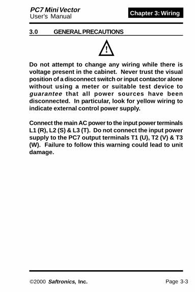
3.0 GENERAL PRECAUTIONS
!
Do not attempt to change any wiring while there isvoltage present in the cabinet. Never trust the visualposition of a disconnect switch or input contactor alonewithout using a meter or suitable test device toguarantee that all power sources have beendisconnected. In particular, look for yellow wiring toindicate external control power supply.
Connect the main AC power to the input power terminalsL1 (R), L2 (S) & L3 (T). Do not connect the input powersupply to the PC7 output terminals T1 (U), T2 (V) & T3(W). Failure to follow this warning could lead to unitdamage.

Page 3-4
Chapter 3: Wiring PC7 Mini VectorUser’s Manual
©2000 Saftronics , Inc.
!
The local codes and the NEC guidelines should befollowed when connecting the wiring.
Please try to run the motor wiring in separate conduitor wire tray from the inverter’s input power wiring.
Branch circuit protection must be provided externallyto comply with the NEC.
Make sure all screws are tightened before any poweris applied to the unit.
Check for loose debris or wire clippings before poweris applied.
Make sure no wires strands are touching adjacentstrands.
Physically separate the inverter’s control wiring frompower wiring. If they must cross, do so at right angles(90°).
Size the incoming power feeder per NEC in keeping thevoltage drop to within 2%, depending upon the wiringdistance.

Page 3-5
Chapter 3: WiringPC7 Mini VectorUser’s Manual
©2000 Saftronics , Inc.
!
3.1 POWER WIRINGNOTE: You must provide branch circuit protectionto comply with the requirements of the NEC and anyother applicable local codes. Do not attempt anywiring unless all power is removed from the drivecabinet and the red Power LED on the control boardis extinguished.
3.1.1 Power Wiring Precautions
Be sure to provide either branch circuit protection (eitherCB or input fuses) between the incoming power sourceand the PC7 inverter.
Make sure that any ground fault interrupter is rated for aminimum of 200 mA earth leakage current to preventnuisance trips.
If the source is greater than 600 KVA you should connecta 3% impedance input line reactor to minimize the shortcircuit currents in the system.
If you choose to connect a contactor between the inverteroutput and the motor, you must make sure the contactoris never switched while the inverter is operating.Otherwise, the peak currents or voltage could causenuisance trips.
Never connect the incoming AC input power to the output
terminals [T1 (U), T2 (V), or T3 (W)].

Page 3-6
Chapter 3: Wiring PC7 Mini VectorUser’s Manual
©2000 Saftronics , Inc.
Separate the incoming power leads from the inverteroutput wiring whenever possible.
Separate control leads (120 V or less) from power leads.If they must cross, make sure they do so at 90° angles.
Use R-C surge suppressors across the coils of allcontactors installed in a control panel with the inverter.
You must install separate motor thermal protection(overload relay or thermostat) whenever more than onemotor is connected to the inverter output.
Make sure the resistance to earth is less than 100 Ω(230 V units) or 10 Ω (460 V units). Never ground theinverter in common with welding machines, large motors,arc furnaces, or other high current devices.
Never connect power factor correction capacitors directlyto the input or output of the PC7.

Page 3-7
Chapter 3: WiringPC7 Mini VectorUser’s Manual
©2000 Saftronics , Inc.
3.1.2 Input Protection
!The following are only recommended values. Youmust always conform to the NEC and local applicablecodes.
You must install branch circuit protection between theinverter input and the incoming AC power supply. Ourrecommendations are given in the table below.
Recommended Input Protection
rebmuNledoM-7CP
esahP-3
sgnitaRtupnI)A(
esuFyaleDemiTBCCM
1P02 1.1 )A5(/A5
2P02 8.1 )A5(/A5
4P02 9.3 )A01(/A5
7P02 4.6 )A02(/A01
5P12 11 )A02(/A02
2P22 1.51 )A04(/A02
7P32 42 )A05(/A03
5P52 43 A05
5P72 54 A06
2P04 6.1 A5
4P04 4.2 A5
7P04 2.4 A5
5P14 0.7 A01
2P24 1.8 A01
7P34 5.31 A02
5P54 8.91 A03
5P74 0.82 A04

Page 3-8
Chapter 3: Wiring PC7 Mini VectorUser’s Manual
©2000 Saftronics , Inc.
3.1.3 Wire Selection RecommendationsThe table below gives recommended minimum wiresizes for the PC7 inverter. You must size the wiring inaccordance with NEC and with locally accepted practices.
Recommended Wire SizesrebmuNledoM
-7CPesahP-3
rewoPMM/GWA( 2)
lortnoCMM/GWA( 2)
1P02 1.2/41 2/41
28.0/81
2P02 1.2/41 2/41
4P02 1.2/41 2/41
7P02 1.2/41 3.3/21
5P12 1.2/41 3.5/01
2P22 3.3/21 3.5/01
7P32 3.3/21 4.8/8
5P52 8/8
5P72 8/8
2P04 1.2/41
4P04 1.2/41
7P04 1.2/41
5P14 1.2/41
2P24 1.2/41
0P44 1.2/41
5P54 5.5/01
5P74 5.5/01

Page 3-9
Chapter 3: WiringPC7 Mini VectorUser’s Manual
©2000 Saftronics , Inc.
The terminal arrangement for 200/400 V class, 3-Phaseinput series 7.5/10 HP is shown below.
Models PC7 - 25P5, 27P5, 45P5, 47P5
3.1.4 Power Interconnect WiringPlease refer to the figure below for the proper powerinterconnections.
Power Interconnect Wiring
Power Interconnect Wiring for 7.5/10 HP
- +1 +2
MOptional
DBResistorInput Power
Supply
L1 L2 L3 B1 B2 T1 T2 T3
R/L1 S/L2 T/L3 - +1 +2 B1 B2 U/T1 V/T2 W/T3

Page 3-10
Chapter 3: Wiring PC7 Mini VectorUser’s Manual
©2000 Saftronics , Inc.
3.1.5 DB Resistor ValuesThe PC7 contains the required electronics for DynamicBraking (DB). DB allows the motor to develop up to 150%rated braking torque for rapid deceleration or to dissipateregenerative loads. You must make sure the DB resistor(connected between terminals B1 and B2 as shown inthe figure on page 3-9) is greater than the followingminimum resistor values.
DB Resistor Values
egatloV egatloV egatloV egatloV egatloV
mumixaM mumixaM mumixaM mumixaM mumixaMelbacilppA elbacilppA elbacilppA elbacilppA elbacilppA
tuptuO tuptuO tuptuO tuptuO tuptuO)Wk(PH )Wk(PH )Wk(PH )Wk(PH )Wk(PH
retrevnI retrevnI retrevnI retrevnI retrevnIledoM ledoM ledoM ledoM ledoM )elcyCytuD%01(rotsiseRgnikarB )elcyCytuD%01(rotsiseRgnikarB )elcyCytuD%01(rotsiseRgnikarB )elcyCytuD%01(rotsiseRgnikarB )elcyCytuD%01(rotsiseRgnikarB
HP3 HP3 HP3 HP3 HP3-7CP -7CP -7CP -7CP -7CP
HP1 HP1 HP1 HP1 HP1-7CP -7CP -7CP -7CP -7CP
rotsiseR rotsiseR rotsiseR rotsiseR rotsiseRnoitacificepS noitacificepS noitacificepS noitacificepS noitacificepS)sttaW/seR( )sttaW/seR( )sttaW/seR( )sttaW/seR( )sttaW/seR(
muminiM muminiM muminiM muminiM muminiM.seR .seR .seR .seR .seR
traP traP traP traP traPrebmuN rebmuN rebmuN rebmuN rebmuN
.ytQ .ytQ .ytQ .ytQ .ytQd'qeR d'qeR d'qeR d'qeR d'qeR
V002
)1.0(31.0)2.0(52.0)4.0(5.0)57.0(1
)5.1(2)2.2(3)7.3(5)5.5(5.7)5.7(01
1P022P024P027P025P122P227P325P525P72
1P0B2P0B4P0B7P0B5P1B2P2B7P3P
--
W001/003W001/003W001/003W001/041
W002/07W002/07W004/04W006/02W009/21
003003002021
0606236.96.9
6082-5006082-5006082-5005082-5005082-500 )1(
5082-500 )1(
8114-5005060-5006060-500
111122111
V004
)2.0(05.0)4.0(57.0)57.0(5.1
)5.1(3)2.2(3)7.3(5)5.5(5.7)5.7(01
2P044P047P045P142P247P345P545P74
-
W001/057W001/057W001/057W002/082W002/022W004/051
W006/07W008/07
057057015042002001
2323
7082-5007082-5007082-5005082-500 )2(
3082-500 )2(
9114-5003124-5004224-500
11122111
lellarapnidetcennocebotsrotsiseR)1(seiresnidetcennocebotsrotsiseR)2(
W001,mho011=3082-500W001,mho041=4082-500W001,mho041=5082-500
knistaehtuohtiwsttaw05knistaehhtiwsttaw001
W001,mho003=6082-500W001,mho057=7082-500
Page 3-11
Chapter 3: WiringPC7 Mini VectorUser’s Manual
©2000 Saftronics , Inc.
3.2 CONTROL WIRING
!Warning: Make sure the input control wiring isconsistent with the programmed start/stopmethod. Wiring 2-wire control inputs into a driveprogrammed for 3-wire control could result inunexpected operation.
3.2.1 Control Wiring Precautions
Physically separate control wiring from power wiring. Ifthey must cross, make sure they do so at 90° angles.
Use twisted, shielded wires for the analog input or outputsignals (use Belden no. 8760 for 2 wire and use Beldenno. 8770 for 3 wire, or their equivalents).
Control wiring must be less than 164 ft. (50 m) in length.Please note: the maximum allowable cable length isinstallation dependent due to electrical noiseconsiderations.
Observe proper grounding methods by connecting onlyone end of the shield sheath to ground. Typically, youshould ground the shield on the inverter’s side.
Separate any 120 VAC control wiring from the DC wiring.Never connect AC power to any input terminals withoutusing a suitable interface card.
Use R-C type surge absorbers across any contactors inthe VFD panel. MOV type absorbers alone are notadequate in reducing electromagnetically coupled noise.
3.2.2 Terminal Locations
The control terminals can be found at the bottom of thecontrol card. These terminals are suitable for 20-16 AWGwire (0.5-1.25 mm2).

Page 3-12
Chapter 3: Wiring PC7 Mini VectorUser’s Manual
©2000 Saftronics , Inc.
3.2.3 Control Terminal LayoutPass the cable through wiring hole and connect. Be sureto mount the cover in its original position.
MA
S3S2S1
FCFRFSR-R+P2P1S7S6S5
MCMB
1312
ION
SW2
VOFF
NPN
PNPSW1
ACAMS-S+ RPSCS4 PC
MBMCMA
321 11
2214
CONTACT OUTPUT
*SW1 can be changed according to input signal polarity.0V common: NPN side24 common: PNP sideRefer to page 4-21 for SW2
Wiring the control circuit terminals
0.22 in.(5.5 mm)
0.016 in. max.(0.4 mm)
0.098 in. max.(2.5 mm)
Insert the wire into the lower part of the terminal blockand connect it tightly with a screwdriver.
Wire sheath strip length mustbe 0.22 in (5.5 mm).
Screwdriver blade width

Page 3-13
Chapter 3: WiringPC7 Mini VectorUser’s Manual
©2000 Saftronics , Inc.
3.2.4 Terminal DefinitionThe PC7 incorporates multi-function type inputs andoutputs in the control circuit. Refer to the table below forthe control circuits and function.
epyT epyT epyT epyT epyT lanimreT lanimreT lanimreT lanimreT lanimreT emaN emaN emaN emaN emaN )leveLlangiS(noitcnuF )leveLlangiS(noitcnuF )leveLlangiS(noitcnuF )leveLlangiS(noitcnuF )leveLlangiS(noitcnuF
1S 1noitcelestupninoitcnuf-itluM :nepo,nurDWF:desolcgnittesyrotcaFnurVER
-otohPrelpuocnoitalusni,cdV42
Am8
2S 2noitcelestupninoitcnuf-itluM :nepo,nurVER:desolcgnittesyrotcaFnurDWF
3S 3noitcelestupninoitcnuf-itluM ON(tluaflanretxE:gnittesyrotcaF)tcatnoc
4S 4noitcelestupninoitcnuf-itluM tesertluaF:gnittesyrotcaF
5S 5noitcelestupninoitcnuf-itluM deepspets-itluM:gnittesyrotcaF1ecnerefer
6S 6noitcelestupninoitcnuf-itluM deepspets-itluM:gnittesyrotcaF2ecnerefer
7S 7noitcelestupninoitcnuf-itluM ecnerefergoJ:gnittesyrotcaF
CS noitcelestupninoitcnuf-itluMnommoc langislortnocroF
PR eslupecnereferdeepsretsaMtupniniart xamzHk03
SF gnittesycneuqerfrofrewoP ).xamAm02tnerrucelbissimrep(V21+
RF ycneuqerfdeepsretsaMecnerefer
)mhok052(Am02ot4ro)mhok02(CDV01+ot0)noituloser0001/1(
CF nommocecnereferycneuqerF V0
AM tuptuotcatnocON
tluaf:gnittesyrotcaFyticapactcatnoC
,sselroA1CAV052sselroA1CDV03
BM tuptuotcatnocCN
CM nommoctuptuotcatnoC
1P 1tuptuorelpuoc-otohP nuR:gnittesyrotcaFtuptuorelpuoc-otohP
roAm05,CDV84+ssel
2P 2tuptuorelpuoc-otohP ycneuqerF:gnittesyrotcaFdeerga
CP nommoctuptuorelpuoc-otohP V0
MA tuptuorotinomgolanA :gnittesyrotcaF01+ot0ycneuqerftuptuO V roAm2,CDV01+
noitulosertib-8,sselCA nommocrotinomgolanA V0
+R )+(tupnisnoitacinummoCnoitacinummocSUBDOM
-SRro584-SRhguorhtnuR224
SUBDOM224/584-SR,locotorp
.xamspk2.91
-R )-(tupnisnoitacinummoC
+S )+(tuptuosnoitacinummoC
-S )-(tuptuosnoitacinummoC
Con
trol C
ircui
tO
utpu
tIn
put
Mul
ti-fu
nctio
nco
ntac
t ou
tput
Freq
uenc
yre
fere
nce
Sequ
ence
Com
mun
icat
ion
Circ
uit T
erm
inal
M
OD
BUS
com
mun
icat
ions
Control Terminal Definitions

Page 3-14
Chapter 3: Wiring PC7 Mini VectorUser’s Manual
©2000 Saftronics , Inc.
DC Reactor(optional)
ThermalOverload
Relay
BrakingResistor(optional)
Factory Jumper
MCCB
L1
L2
L3
Forward Run
Reverse Run
Ext Fault (NO)
Fault ResetMulti-Step Speed Ref 1Multi-StepSpeed Ref 2
Jog Reference
Multi-FunctionInput
FrequencyReference
Pulse Train Input
2 K Ω
ModbusCommunicationsRS-485/422Max. 19.2 KBPS
R+
R-
S+
S-
AM
AC
Output FrequencyPulse Monitor/AnalogMonitor Selectable
FMAnalog MonitorOutput0 - 10 Vdc, 2 mA
DigitalOperatorControlSetting Min Max
P1
P2
PC
MA
MB
MC
T1
T2
T3
IM
Multi-FunctionContact Output250 Vac, 1A30 Vdc, 1A
Multi-FunctionPhotocoupler Output+48 Vdc, 50 mA
S1
S2
S3
S4
S5
S6
S7SC
Shield Ground
RP
FS
FR
FC
Pulse Train Input (30 kHz)
Power Supply(+12 V, 20 mA)
Frequency Ref.0 to +10 V (20 k Ω)4 to 20 mA (250 Ω)
PC7
+2 +1 B1 B2-
3.2.5 Standard I/O Wiring

Page 3-15
Chapter 3: WiringPC7 Mini VectorUser’s Manual
©2000 Saftronics , Inc.
3.3 GROUNDINGWarning: A solid ground is required for personnelsafety and to guarantee reliable, nuisance freeoperation.
!
You must provide a low impedance ground connection tothe PC7 on the green Earth Ground terminal on theheatsink assembly.
The resistance to ground must be less than 100 Ω(230 V units) or 10 Ω (460 V units). You should alwayskeep the ground connections as short as possible.
Never ground the PC7 in common with large currentequipment such as welding machines, arc furnaces, orlarge motors.
If you have an installation with multiple inverter units, besure to follow the wiring practice given in the figure below.
Proper Grounding Methods
PC7#3
PC7#3
PC7#3
OK
OK
NOTOK
EarthEarthEarth
EarthEarthEarth
EarthEarthEarth
PC7#2
PC7#2
PC7#2
PC7#1
PC7#1
PC7#1

Page 3-16
Chapter 3: Wiring PC7 Mini VectorUser’s Manual
©2000 Saftronics , Inc.
This page intentionally left blank.

Page 4-1
Chapter 4: ProgrammingPC7 Mini VectorUser’s Manual
©2000 Saftronics , Inc.
Chapter 4:
Programming
What this chapter tells you:1) Introduction to the PC7 keypad.2) Quick setup for PC7.3) Simple programming examples.4) Programming
- First Functions (pg. 4-10)- Second Functions (pg. 4-36)- Third Functions (pg. 4-48)- Fourth Functions (pg. 4-64)
Note: Refer to Appendix A for a complete listing ofparameters
Page 4-2
Chapter 4: Programming PC7 Mini VectorUser’s Manual
©2000 Saftronics , Inc.
Note: This chapter must be read in its entirety beforeany programming changes are attempted. Onlyauthorized personnel should modify the invertersettings as power is applied and lethal voltages maybe present.
!
4.0 PROGRAMMING
This chapter details the programming of the PC7 inverterunit. The programming parameters are organized in anumeric fashion with an appropriate FUNCTION code(“N” prefix). These parameters shouldn’t be changedunnecessarily.
The first part of the chapter deals with the programmingmethod. Step-by-step programming examples are thenprovided for some of the more commonly changedparameters. Finally, a complete parameter list isprovided in Appendix A.
4.1 KEYPAD LAYOUT
4.2 KEY FUNCTIONS
The PC7 keypad has 6 buttons and 7 LEDs as shown onthe facing page. Please refer to page 4-4 for a detaileddescription of the LEDs.
You will only need to use the display (DSPL) and enterkeys and the arrow keys to setup the inverter.

Page 4-3
Chapter 4: ProgrammingPC7 Mini VectorUser’s Manual
©2000 Saftronics , Inc.
FREF FOUT IOUT MNTR
F/R LO/RE PRGM
DIGITALOPERATORJVOP-140
MIN MAX
DSPL RUN
DATAENTER
STOPRESET
4.2.1 Display Key DSPL
The Display (DSPL) key is context sensitive and has mul-tiple functions. It is used to navigate between the variousdrive (operating) modes and the programming (setup)mode. It is also used to switch the display function be-tween the FUNCTION LED’s and between the edit screenfor each PROGRAM.
4.2.2 Up/Down Arrows <<
These keys are used to edit the selected data. Thesekeys will allow fine-tuning or a quick scroll, dependingupon the length of time the key is depressed.

Page 4-4
Chapter 4: Programming PC7 Mini VectorUser’s Manual
©2000 Saftronics , Inc.
FORFORFORFORFOR (forward run) RRRRREEEEEV V V V V (reverse run)
4.2.3 Basic LED Description
FREF
By pressing DSPL on the digital operator, each of thefunction LED’s can be selected.
The following flowchart describes each function LED.
Power ON
Frequency referencesetting/monitor (Hz)Sets PC7 operation speed.
Output frequency monitor (Hz)Displays frequency that PC7is currently outputting.Setting disabled.
Output current monitor (A)Displays current that PC7is currently outputting.Setting disabled.
Multi-function monitorDescription of the selectedmonitor is displayed.(see pg. 2-8 and 2-9)
FWD/REV run selectionSets the motor rotation directionwhen run command is given bythe digital operator.
DSPL
DSPL
DSPL
DSPL
FOUT
IOUT
MNTR
F/R
DSPL
If the PC7 losespower while in one ofthese modes, it willreturn to this modeonce power isrestored.
Monitor No.U-01: Frequency
reference (FREF)U-02: Output frequency (FOUT)U-03: Output current (IOUT)U-04: Output voltage reference
(Unit: 1V)U-05: DC Bus voltage (Unit: 1V)U-06: Input terminal statusU-07: Output terminal statusU-08: Torque monitorU-09: Fault HistoryU-10: Software No.U-11: Output powerU-15: Data reception errorU-16: PID feedbackU-17: PID outputU-18: PID output
fg

Page 4-5
Chapter 4: ProgrammingPC7 Mini VectorUser’s Manual
©2000 Saftronics , Inc.
4.2.4 Switching LOCAL/REMOTE ModesThe following functions can be selected by switchingthe LOCAL or REMOTE mode. To select RUN/STOPcommands or frequency reference, change the mode inadvance depending on the following applications.
• LOCAL mode: Enables the digital operator forRUN/STOP commands and FWD/REV runcommands. Frequency reference can be set byvolume or FREF
• REMOTE mode: RUN/STOP commands andFWD/REV run commands can be given by thedigital operator, control circuit terminal ortransmission.n003 = 0: Enables digital operator (LOCAL)
= 1: Enables control circuit terminal (REMOTE)= 2: Enables transmission (MODBUS
communications)Setting of frequency reference selection (n004)becomes valid. (Refer to page 4-7)
• How to select LOCAL/REMOTE modesWhen LOCAL/REMOTEswitching function is not set formulti-function input selection
When LOCAL/REMOTE switchingfunction is set for multi-functioninput selection
Select LO foroperator LO/REselection.
Select RE foroperator LO/REselection.
Set multi-functioninput terminal isturned ON.
Set multi-functioninput terminal isturned OFF.
LOCAL mode REMOTE mode
(When 17 is set toany of constantsn050 to n056)
(When 17 isnot se t toany ofcons tan tsn050 to n056)

Page 4-6
Chapter 4: Programming PC7 Mini VectorUser’s Manual
©2000 Saftronics , Inc.
• LOCAL mode
When LO (local mode) is selected for digitaloperator LO/RE selection, run operations (run/stop) is enabled by the STOP or RUN button ofthe digital operator, and forward/reverse run isenabled by blinking F/R lamp (using or key).
• REMOTE mode- Select remote mode.
Following are two methods to select remote modes.1. Select rE (remote mode) for LO/RE selection.2. When the local/remote switching function is
selected for multi-function input selection, turnOFF the input terminal to select remote mode.
- Select operation method by setting the constantn003.
4.2.5 Selecting RUN/STOP CommandsRefer to switching LOCAL/REMOTE modes (page 4-5) toselect either the LOCAL mode or REMOTE mode.Operation method (RUN/STOP commands, FWD/REVrun commands) can be selected by the following method.
<
n003 = 0 : Enables the digital operator (same with local mode).= 1 : Enables the multi-function input terminals (figure on
following page).= 2 : Enables serial communications (refer to page 4-76).= 3 : Enables communication card (optional)
<

Page 4-7
Chapter 4: ProgrammingPC7 Mini VectorUser’s Manual
©2000 Saftronics , Inc.
Example for using the multi-function input terminal asoperation reference (two-wire sequence).For an example of three-wire sequence, refer to page4-24.
Note: When inverter is operated without the digitaloperator, always set the constant n010 to 0.
n010 =0 :Digital operator connection fault is not detected (initialsetting).
=1 :Digital operator connection fault is detected.• Operating (RUN/STOP commands) by communica-
tions Setting constant n003 to 2 in REMOTE mode cangive RUN/STOP commands by communication(MODBUS communications). For the command bytransmission, refer to page 4-76.
4.2.6 Selecting Frequency Reference (n004)Frequency reference can be selected by the followingmethods.
• Setting by operatorSelect REMOTE or LOCAL mode in advance. Formethod for selecting the mode, refer to page 4-5.
- LOCAL mode
Select command method by constant n004.
n004 = 0 : Enables the setting by potentiometer on digital operator.= 1 : Enables the digital setting by digital operator, setting value is
stored in constant n024 (frequency reference 1).
FWD RUN/STOPREV RUN/STOP
S1
S2
SC
IM
n003 : 1 (Initial setting : 0)n050 : 1 (Initial setting)n051 : 2 (Initial setting)

Page 4-8
Chapter 4: Programming PC7 Mini VectorUser’s Manual
©2000 Saftronics , Inc.
• Digital setting by digital operatorInput frequency while FREF is lit (ENTER aftersetting the numeric value).
- LOCAL modeSelect command method by parameter n008.n008 = 0 :Enables the setting by potentiometer on digital operator.
= 1 :Enables the digital setting by digital operator. (Initial setting)Factory setting of the model with digital operator (withpotentiometer) JVOP-140 is n008=0.
* Frequency reference setting is effective when 1(factory setting) is set to constant n009 instead ofpressing ENTER key
n009 = 0 :Enables frequency reference setting by ENTER key.= 1 :Disables frequency reference setting by ENTER key.
- REMOTE modeSelect command method by constant n004.
n004 = 0 :Enables frequency reference setting by potentiometer ondigital operator.
= 1 :Effective frequency reference 1 (constant n024)= 2 :Voltage reference (0 to 10V) (See figure below)= 3 :Current reference (4 to 20mA) (Refer to page 4-22)= 4 :Current reference (0 to 20mA) (Refer to page 4-22)= 5 :Pulse train reference (Refer to page 4-75)= 6 :Communication (Refer to page 4-76)=7 : Voltage reference from digital operator circuit terminal (0-10V)
(CN2)=8 : Current reference from digital operator circuit terminal
(4-20mA) (CN2)=9 : Communication

Page 4-9
Chapter 4: ProgrammingPC7 Mini VectorUser’s Manual
©2000 Saftronics , Inc.
Example of frequency reference by a voltage signal
• Setting by transmissionLOCAL/REMOTE switching function is selected formulti-function input selection, turn OFF the terminalinput to set the remote mode.
MASTER SPEEDFREQUENCYREFERENCE
(0 to +10V)
FS(frequencysetting power+12V, 20mA)FR
FC (0V)2KΩ
IM
n004 : 2 (Initial setting : 0)

Page 4-10
Chapter 4: Programming PC7 Mini VectorUser’s Manual
©2000 Saftronics , Inc.
4.3 FIRST FUNCTION (n001 - n039)Factory settings of the constants are shown as in the tables.
4.3.1 Constant Set-up and Initialization (n001)
The following table describes the data which can be setor read when n001 is set.
Unused constants among n001 to n179 are notdisplayed.
100ngnitteS
tahttnatsnoCtesebnac
tahttnatsnoCdeweivebnac
0 100n 971not100n
1 *940not100n 940not100n
2 *970not100n 970not100n
3 *911not100n 911not100n
4 *971not100n 971not100n
5 desutoN
6 deraelcyrotsihtluaF
01 )ecneuqeseriw2(ezilaitinI
11 )ecneuqeseriw3(ezilatinI
*Excluding setting disabled constants.

Page 4-11
Chapter 4: ProgrammingPC7 Mini VectorUser’s Manual
©2000 Saftronics , Inc.
NOTE: “““““EEEEERRRRRRRRRR” ” ” ” ” appears on the LED display for onesecond and the set data returns to its initial values inthe following cases:
(1) The set values of input terminal function selectionS1 to S7 (n050 to n056) are the same.
(2) If the following conditions are not satisfied in theVolt/Hz pattern setting (V/f pattern setting):Max. output frequency (n011) Max. voltage output
frequency (n013) > Mid. output frequency (n014)
Min. output frequency (n016)For details, refer to “Adjusting torque according toapplication” (V/f pattern setting) on page 4-15.
(3) If the following conditions are not satisfied in theJump frequency setting:Jump frequency 3 (n085) Jump frequency 2 (n084)
Jump frequency 1 (n083)(4) If frequency reference lower limit (n034)
Frequency reference upper limit (033)
(5) If Electronic thermal reference current (n036)150% of inverter rated current
(6) Constant n018 is set to 1 (accel/decel time unit is0.01 sec.) when n018 is set to 0 and the valueexceeding 600.0 sec. is set to accel/decel time(n019 to n022).
>=
<=
<=<=
<=
<=

Page 4-12
Chapter 4: Programming PC7 Mini VectorUser’s Manual
©2000 Saftronics , Inc.
4.3.2 Control Method (n002)
4.3.3 Precaution for V ector Control Application
For optimal performance in the vector mode, the motorparameter data must be programmed in the PC7. Thefollowing parameters must be programmed with themotor nameplate data.
.oN .oN .oN .oN .oN emaN emaN emaN emaN emaN tinU tinU tinU tinU tinU egnaRgnitteS egnaRgnitteS egnaRgnitteS egnaRgnitteS egnaRgnitteS laitinI laitinI laitinI laitinI laitinIgnitteS gnitteS gnitteS gnitteS gnitteS
601n pilsdetarrotoM zH1.0 zH0.02ot0.0 *
701n enil-ot-enilrotoMecnatsiser
100.0 W nahtssel( 10W)10.0 W 1( 0W )eromro .56ot000.0 05 W *
630n tnerrucdetarrotoM A1.0 retrevnifo%051ot0tnerrucdetar *
011n daol-onrotoMtnerruc %1 rotom=%001(%99ot0
)tnerrucdetar 051
Determine the proper control method for the application.
Open Loop Vector Control - Parameter n002 = 1. Openloop vector control method should be used for mostconstant torque applications of the PC7. With this controlmethod there is excellent starting torque and speedregulation.V/f Control - Parameter n002 = 0. V/f control should beused for most variable torque applications. Variabletorque applications would include: fan, blower,centrifugal pump, and mixers. Generally, variable torqueloads do not require high levels of starting torque. V/fcontrol can also be used for some constant torque loadswhere starting torque and speed regulation are not criti-cal and multiple motor applications.
*Setting depends on inverter capacity.

Page 4-13
Chapter 4: ProgrammingPC7 Mini VectorUser’s Manual
©2000 Saftronics , Inc.
Adjustment of torque compensation time parameter(n104) and torque iron loss compensation parameter(n105) are normally not required.
Adjust torque compensation parameter under the follow-ing conditions:
• Increase setting when the motor generates vibration.• Reduce setting when motor response is low.
To adjust for slip compensation gain (n111), reduce loadso that motor speed reaches target value. Increase ordecrease the value by 0.1.
- When speed is less than target value, increase slipcompensation gain.
- When speed is more than target value, reduce slipcompensation gain.
Adjustment of slip compensation gain time parameter(n112) is normally not required. Adjust under the follow-ing conditions:
- Reduce the setting when response is slow.- Increase the setting when speed is unstable.

Page 4-14
Chapter 4: Programming PC7 Mini VectorUser’s Manual
©2000 Saftronics , Inc.
(3) Motor rated current (n036)= Output current with 100% load at (nameplate FLA)
(4) Motor no-load current (n110)
Example11.743.0
No-load output current at 60HzRated Full Load Amp (FLA)
= x 100
= 27%
4.3.4 Motor Constant Calculation
The following shows an example of motor constantcalculation.
(1) Motor rated slip (n106)Synchronous speed at - Motor speed with 100%(nameplate RPM) load at (nameplate RPM)
120 / Motor Poles
Example1800 - 1763 (r / min)
120 / 4
(2) Motor line-to-line resistance (n107)Line-to-line resistance of x 273 = (25oC + Insulation class temperature) / 2insulation class temperature 273 + Insulation class temperature
Example273 + (25 + 115) / 2 273 + 115
= 1.2 Hz
=
=
0.145 x = 0.128Ω

Page 4-15
Chapter 4: ProgrammingPC7 Mini VectorUser’s Manual
©2000 Saftronics , Inc.
Adjust motor torque by using “V/f pattern” and “full-rangeautomatic torque boost”.• V/f pattern setting
Set V/f pattern by n011 to n017 as described below. Seteach pattern when using a special motor (high-speedmotor, etc.) or when requiring special torque adjustmentof machine.
Set 106 (motor rated slip), n036 (motor rated current), n107 (motor line-to-line resistance) and n110 (motor no-load current) according to themotor test report.To connect a reactor between the inverter and the motor, set n108 to thevalue of “n108 (leaking inductance) initial value + externally-mountedreactor value”. Unless a reactor is connected, n108 (leaking inductance)does not have to be set according to the motor.
4.3.5 Using V/f Mode
Be sure to satisfy the follow-ing conditions for the settingof n011 to n017.n016 n014 < n013 n011If n016 = n014 is set, the setvalue of n015 is disabled.
<= <=
stnatsnoCrebmuN emaN tinU egnaRgnitteS laitinI
gnitteS
110n ycneuqerftuptuo.xaM zH1.0 zH004ot05 zH06
210n egatlov.xaM V1 V552ot1)V015ot1.0(
V032)V064(
310n ycneuqerftuptuoegatlov.xaM)ycneuqerfesab( zH1.0 zH004ot2.0 zH06
410n ycneuqerftuptuo.diM zH1.0 zH9.993ot1.0 zH5.1
510n egatlovycneuqerftuptuo.diM V1 V552ot1.0)V015ot1.0(
V21)V42(
610n ycneuqerftuptuo.niM zH1.0 zH01ot1.0 zH5.1
710n egatlovycneuqerftuptuo.niM V1 V05ot1)V001ot1.0(
V21)V42(

Page 4-16
Chapter 4: Programming PC7 Mini VectorUser’s Manual
©2000 Saftronics , Inc.
(2) For fans/pumpsMotor Specifications: 60 Motor Specifications: 50
• Typical setting of V/f patternSet the V/f pattern according to the application asdescribed below. For 400V class, the voltagevalues(n012, n015, and n017) should be doubled. Whenrunning at a frequency exceeding 50Hz/60Hz, changethe maximum output frequency (n011).
NOTE: Be sure to set the maximum output frequencyaccording to the motor characteristics.
(1) For general-purpose applications
Motor Specifications: 60 Motor Specifications: 50(Factory Setting)

Page 4-17
Chapter 4: ProgrammingPC7 Mini VectorUser’s Manual
©2000 Saftronics , Inc.
(3) For applications requiring high starting torqueMotor Specifications: 60 Motor Specifications: 50
Increasing voltage of V/f pattern increases motor torque,but an excessive increase may cause motor overexcitation,motor overheat or vibration.
NOTE: n012 is to set to motor rated voltage.
When operating with frequency larger than 60Hz, changeonly maximum output frequency (n011).
PARAMETER TORQUE
PARAMETER OUTPUTVARIABLE OUTPUT
BASE POINT
n013= 60Hz
n011= 90Hz
n012= 200Hz

Page 4-18
Chapter 4: Programming PC7 Mini VectorUser’s Manual
©2000 Saftronics , Inc.
Full-range automatic torque boost (only when in V/f moden002 = 0) Motor torque requirement changes according toload conditions. Full-range automatic torque boost adjustsvoltage of V/f pattern according to the requirement. ThePC7 automatically adjusts the voltage during constant-speed operation as well as during acceleration.The required torque is calculated by the inverter.This ensures tripless operation and energy-saving effects.
Output voltage ααααα Automatic torque boost gain (n103) x Required torque
Required torque a Increase voltage
f (Frequency)
V (Voltage)
• Operation
Normally, no adjustment is necessary for automatic torqueboost gain (n103 factory setting : 1). When the wiringdistance between the inverter and the motor is long, orwhen the motor generates vibration, decrease theautomatic torque boost gain (n103).
Note: α means proportional to

Page 4-19
Chapter 4: ProgrammingPC7 Mini VectorUser’s Manual
©2000 Saftronics , Inc.
As the load becomes larger, motor speed is reduced andmotor slip value is increased. The slip compensating func-tion controls the motor speed at a constant value even ifthe load varies.When inverter output current is equal to the motor ratedcurrent (electronic thermal reference current, n036), thecompensation frequency is added to the output frequency.
Compensation frequency = Motor rated slip (n106)
4.3.6 When Torque is not sufficient at Low SpeedIf sufficient torque cannot be obtained, change the V/fpattern settings of n011 to n017 to those for high-start V/f.
4.3.7 Decreasing Motor Speed Fluctuation
Output current - Motor no-load current (n110)Motor rated current - Motor no-load current (n110)
X
Slip Compensation gain (n111)X

Page 4-20
Chapter 4: Programming PC7 Mini VectorUser’s Manual
©2000 Saftronics , Inc.
Refer to switching LOCAL/REMOTE modes (page 4-5) toselect either the LOCAL mode or REMOTE mode.Operation method (RUN/STOP commands, FWD/REV runcommands) can be selected by the following method.
• LOCAL modeWhen LO (local mode) is selected for digital operatorLO/RE selection, run operations (run/stop) is enabledby the STOP or RUN button on the digital operator, andforward/reverse run is enabled by blinking F/R lamp(using or key).LO/RE is not effective when local/remote switchingfunction is selected for multi-function input selection.
Related ParameterssretemaraP
rebmuN emaN tinU egnaRgnitteS yrotcaFgnitteS
630n tnerrucdetarrotoM A1.0 tnerrucdetarretrevnifo%051ot0 *
111n niagnoitasnepmocpilS 1.0 5.2ot0.0 0.0
011n tnerrucdaol-onrotoM %1 tnerrucdetarrotoM=%001(%99ot0)630n *
211n yramirpnoitasnepmocpilSemityaled s1.0
s5.52ot0.0semocebemityaled,tessis0.0nehW
.s0.2s0.2
601n pilsdetarrotoM 1.0 02ot0.0 *
* Differs depending on inverter capacity.
(1) Slip compensation is not performed in the followingcondition: Output frequency < minimum output frequency(n016).
(2) Slip compensation is not performed during regenera-tion.
(3) Slip compensation is not performed when motor ratedcurrent (n036) is set to 0.0A.
(4) Parameter n113 enables or disables slip compensa-tion during regeneration. Factor setting is disabled.
4.3.8 Selecting RUN/STOP Commands (n003)
<
<
NOTE:

Page 4-21
Chapter 4: ProgrammingPC7 Mini VectorUser’s Manual
©2000 Saftronics , Inc.
• REMOTE mode- Select remote mode.
Following are two methods to select remote modes.1. Select “rErErErErE” (remote mode) for LO/RE selection.2. When the local/remote switching function is
selected for multi-functIon input selection, turnOFF the input terminal to select remote mode.
- Select operation method by setting the constant n003.
n003 = 0 :Enables the digital operator (same with local mode)(Factory Setting)
= 1 :Enables the multi-function input terminal (see fig. below)= 2 :Enables communications (refer to page 4-76)
Example for using the multi-function input terminal asoperation reference (two-wire sequence).
For example of three-wire sequence, refer to page 4-24.
FWD RUN/STOPREV RUN/STOP
S1
S2
SC
IM
n003 : 1 (Initial setting : 0)n050 : 1 (Initial setting)n051 : 2 (Initial setting)
When inverter is operated without the digital operator,always set the constant n010 to 0.
n010 = 0 :Digital operator connection fault is not detected(initial setting).
= 1 :Digital operator connection fault is detected.• Operating (RUN/STOP commands) by communica-
tions Setting constant n003 to 2 in REMOTE mode cangive RUN/STOP commands by communication(MODBUS communications). For the command bytransmission, refer to page 4-76).
NOTE:

Page 4-22
Chapter 4: Programming PC7 Mini VectorUser’s Manual
©2000 Saftronics , Inc.
4.3.9 Selecting Frequency by Current ReferenceInput (n004)
When setting frequency byinputting current reference(4-20mA) from control circuitterminal FR, switch the dipswitch SW2 on the controlcircuit board to “I” side.SW2 is accessed by removingthe digital operator.
SW2SW2
V I
NOTE:
Never input voltage reference to control circuit terminal FRwhen DIP switch SW2 is switched to “I” side.Current reference selectionSelect current reference as shown below.
4-20mA.....n004 = 30-20mA.....n004 = 4
Refer to 4-7 for more information on n004.

Page 4-23
Chapter 4: ProgrammingPC7 Mini VectorUser’s Manual
©2000 Saftronics , Inc.
After changing DIP switch (SW2), select PRGM on thedigital operator, then set the following constants.
Press the digital operator keys torun or stop the inverter. Switchrun and stop direction by settingF/R LED.
Set frequency by the analogcurrent signal [0-100% (max.frequency)/4-20mA] connected tothe control circuit terminal.
Switch run/stop and FWD/REVrun with switching deviceconnected to the control circuitterminal (2-wire start/stop).
Multi-function input terminals S1and S2 are set to Forward run /stop (n050 = 1) and Reverse RUN/STOP (n051 = 2) respectively.
Set frequency by the analogcurrent signal [0-100% (max.frequency)/4-20mA] connected tothe control circuit terminal.
Frequency reference gain (n060)/bias (n061) can be seteven when current reference input is selected. For details,refer to “Adjusting Frequency Reference Signal” on page4-41.
FS
CurrentReference4-20mA or0-20mA(nn04=3 or 4)
- Setting : n003 = 0, n004 = 3
FCFR
IM
FC
FR
SC
S2
S1
CurrentReference4-20mA or0-20 mA(n004+3or4)
FWDRun/StopREV Run/Stop
- Setting : n003 = 1
IMS

Page 4-24
Chapter 4: Programming PC7 Mini VectorUser’s Manual
©2000 Saftronics , Inc.
When 0 is set at the terminal S3 (n052), terminal S1becomes run command, terminal S2 becomes stopcommand, and terminal S3 becomes FWD/REVcommand.
STOP SW(NC Contact) Run command
(Run when “closed”)
RUN SW(NO Contact)
S1S2
S3
SC FWD run when “open”REV run when “closed”
FWD/REV run selection
Stop Command(Stop when “open”)
• LOCAL/REMOTE select (setting: 17)(Refer to page 4-37)Selects operation reference by the digital operator or bythe multi-function input terminal. LOCAL/REMOTEselect is abailable only during stop.
Frequency reference changes according to the setting of
Open : Run according to the setting of run command selection(n003) or frequency reference selection (n004).
Closed: Run by frequency reference and run command fromthe digital operator.
Example: Set n003 = 1, n004 = 2, n008 = 0Open : Run by frequency reference from multi-function input
terminal FR and run command from multi-functionterminals S1 to S7.
Closed: Run by volume frequency reference and run commandfrom the digital operator.
Terminal Function - 3-Wire Sequence Selection

Page 4-25
Chapter 4: ProgrammingPC7 Mini VectorUser’s Manual
©2000 Saftronics , Inc.
4.3.10 Selecting Stopping Method (n005)Selects the stopping method suitable for the application.
gnitteS noitpircseD
0 potSotnoitareleceD
1 potsottsaoC
• Deceleration to stopExample when accel/decel time 1 is selected
Upon removal of the FWD (REV) run command, themotor decelerates at the decel rate determined by thetime set to decel time 1 (n020) and DC injection brakingis applied immediately before stop. If the decel time isshort or the load inertia is large, overvoltage (OV) faultmay occur at deceleration. In this case, increase thedecel time or install an optional braking resistor.
Braking Torque:Without braking resistor: Approx. 20% torque
of motor rating
With braking resistor: Approx. 150% torqueof motor rating

Page 4-26
Chapter 4: Programming PC7 Mini VectorUser’s Manual
©2000 Saftronics , Inc.
4.3.11 Setting Reverse Run Prohibit (n006)“Reverse run disabled” setting does not accept a reverserun command from the control circuit terminal or digitaloperator. This setting is used for applications where areverse run command can cause problems.
gnitteS noitpircseD
delbanenuresreveR
1 delbasidnuresreveR
4.3.12 Operator Stop Key Selection (n007)
Selects processing when STOP key is pressed duringoperation from multi-function input terminal.
gnitteS noitpircseD
0
noitcnuf-itlummorfgninnurnehwevitceffeyekPOTSeht,desserpsiyekPOTSnehW.slanimrettupni
.500ntnatsnocfognittesehtotgnidroccaspotsretrevnisyalpsidrotarepolatigideht,emitsihttA " PTS PTS PTS PTS PTS " mrala
.)gniknilb(htoblitnuretrevniehtnidlehsidnammocpotssihT
.nepoerasdnammocnuresreverdnadrawrof
1 noitcnuf-itlummorfgninnurnehwevitceffeniyekPOTS.slanimrettupni
n008 Refer to page 4-8n009 Refer to page 4-8n010 = 0 : Digital operator connection fault is not detected
(Factory Setting)= 1 : Digital operator connection fault is detected
n011-n017 Refer to control method (n002) page 4-15
Volts per Hertz Setting

Page 4-27
Chapter 4: ProgrammingPC7 Mini VectorUser’s Manual
©2000 Saftronics , Inc.
4.3.13 Using Two Accel/Decel Times (n018 to n022)• n018 Setting
.oN gnitteS tinU egnaRgnitteS
810n
0 .ces1.0 )sselro.ces0001(.ces9.999-0.0)eromro.ces0001(.ces0006-0001
1 .ces10.0 )sselro.ces001(.ces99.99-00.0)eromro.ces001(.ces006-0.001
- If the numeric value exceeds 600 sec., set accel/deceltime n018 = 0 (in units of 0.1 sec.)
- Accel timeSet the time needed for output frequency to reach 100%from 0%
- Decel timeSet the time needed for output frequency to reach 0%from 100%
*When “deceleration to a stop” is selected (n005 = 0)
OutputFrequency
Accel Time 1(n019)
Decel Time 1(n020)
Accel Time 2(n021)
Decel Time 2*(n022)
Decel Time 1*(n020)
TIME
ON
ON
ON
Forward (Reverse)Run CommandMulti-StepSpeed ReferenceAccel/DecelTime Selection(Terminals S3 to S7)
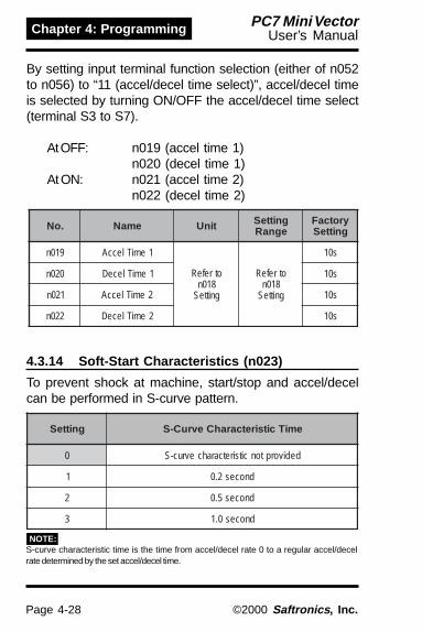
Page 4-28
Chapter 4: Programming PC7 Mini VectorUser’s Manual
©2000 Saftronics , Inc.
By setting input terminal function selection (either of n052to n056) to “11 (accel/decel time select)”, accel/decel timeis selected by turning ON/OFF the accel/decel time select(terminal S3 to S7).
At OFF: n019 (accel time 1)n020 (decel time 1)
At ON: n021 (accel time 2)n022 (decel time 2)
.oN emaN tinU gnitteSegnaR
yrotcaFgnitteS
910n 1emiTleccA
otrefeR810ngnitteS
otrefeR810ngnitteS
s01
020n 1emiTleceD s01
120n 2emiTleccA s01
220n 2emiTleceD s01
4.3.14 Soft-Start Characteristics (n023)
To prevent shock at machine, start/stop and accel/decelcan be performed in S-curve pattern.
gnitteS emiTcitsiretcarahCevruC-S
0 dedivorptoncitsiretcarahcevruc-S
1 dnoces2.0
2 dnoces5.0
3 dnoces0.1
S-curve characteristic time is the time from accel/decel rate 0 to a regular accel/decelrate determined by the set accel/decel time.
NOTE:

Page 4-29
Chapter 4: ProgrammingPC7 Mini VectorUser’s Manual
©2000 Saftronics , Inc.
FWDRUN/STOP
REV RUN/STOP
MULTI-STEPSPEED REF 1
MULTI-STEPSPEED REF 2
MULTI-STEPSPEED REF 3
EXTERNAL FAULT
FAULT RESET
S1
S7
S6
S5
S2
S3
SC
S4
4.3.15 Setting Preset Speeds (n024 to n031)By combining frequency reference and input terminalfunction selections, up to 16 preset speeds can be set.
8-Step Speed Changen003 = 1 (Operation mode selection)n004 = 1 (Frequency reference selection)n024 = 25 (Frequency reference 1)n025 = 30 (Frequency reference 2)n026 = 35 (Frequency reference 3)n027 = 40 (Frequency reference 4)n028 = 45 (Frequency reference 5)n029 = 50 (Frequency reference 6)n030 = 55 (Frequency reference 7)n031 = 60 (Frequency reference 8)
n054 = 6 (Multi-function contact input terminal 5)n055 = 7 (Multi-function contact input terminal 6)n056 = 8 (Multi-function contact input terminal 7)n053 = 1
n050 = 1 (Input terminal S1) Factory Settingn051 = 2 (Input terminal S2) Factory Settingn052 = 3 (Input terminal S3) Factory Settingn053 = 5 (Input terminal S4) Factory Settingn054 = 6 (Input terminal S5) Factory Settingn055 = 7 (Input terminal S6) Factory Settingn056 = 10 (Input terminal S7) Change the setting to 8
NOTE:
When n004 is set at 1, 2, 3, 4,5, or 6, frequency reference1 (n024) becomes disabled.
Only when multi-step speedinput ref. 1 is closed and n077= 1, the effective frequencyreference becomes the CN2analog input signal.
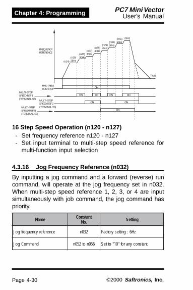
Page 4-30
Chapter 4: Programming PC7 Mini VectorUser’s Manual
©2000 Saftronics , Inc.
16 Step Speed Operation (n120 - n127)- Set frequency reference n120 - n127- Set input terminal to multi-step speed reference for
multi-function input selection
4.3.16 Jog Frequency Reference (n032)
By inputting a jog command and a forward (reverse) runcommand, will operate at the jog frequency set in n032.When multi-step speed reference 1, 2, 3, or 4 are inputsimultaneously with job command, the jog command haspriority.
emaN tnatsnoC.oN gnitteS
ecnereferycneuqerfgoJ 230n zH6:gnittesyrotcaF
dnammoCgoJ 650not250n tnatsnocynarof"01"otteS
FREQUENCYREFERENCE
(n24)(n25)25Hz
(n30)50Hz(n29)
45Hz(n28)40Hz(n27)
35Hz(n26)30Hz
25Hz(n31)55Hz
TIME
ON
FWD (REV)RUN/STOP
MULTI-STEPSPEED REF 1(TERMINAL S5) MULTI-STEP
SPEED REF 2(TERMINAL S6)MULTI-STEP
SPEED REF31(TERMINAL S7)
ON
ON
ONON
ONONON

Page 4-31
Chapter 4: ProgrammingPC7 Mini VectorUser’s Manual
©2000 Saftronics , Inc.
4.3.17 Adjusting Upper/Lower Limits (n033 to n034)• Frequency reference upper limit (n033)
Sets the upper limit of the frequencyreference in units of 1%.(n011 : Maximum output frequency = 100%)*Factory setting : 100%
• Frequency reference lower limit (n034)Sets the lower limit of the frequencyreference in units of 1%.(n011 : Maximum output frequency = 100%)When operating at frequency reference 0,operation is continued at the frequencyreference lower limit.
However, when frequency reference lowerlimit is set to less than the minimum outputfrequency (n016), operation is notperformed.*Factory setting : 0%

Page 4-32
Chapter 4: Programming PC7 Mini VectorUser’s Manual
©2000 Saftronics , Inc.
gnitteS gnitteS gnitteS gnitteS gnitteS noitpircseD noitpircseD noitpircseD noitpircseD noitpircseD
0··········
)eromdnazH001(zH1.0,)zH001nahtssel(zH10.0:tinugnitteS)430n(timilrewolecnereferycneuqerFx)110n(xamFnim:egnargnitteS
zH004,)330n(timilreppuecnereferycneuqerF)110n(xamFot
1··········
)110n(xamF/%0.001:%1.0fostinunignitteSycneuqerFot)430n(timilrewolecnereferycneuqerFnim:egnargnitteS
%001)110n(xamF/zH004(,)330n(timilreppuecnerefer
93ot2
·····
·····
·····
530n/)zH(ecnereferycneuqerFx021=nim/r:nim/r1fostinunignitteS)530nrofseloprotomforebmunehtteS(
timilrewolecnereferycneuqerF)110n(xxamF(021nim:egnargnitteStimilreppuecnereferycneuqerFx)110n(xamF(x021~530n/)430n(
nim/r9999,P021xzH004,530n))330n(xamFfoeulavtes(ecnereferycneuqerffo%001taeulavyalpsidehtteS
.530nfo1ta))110n(
993ot04
·····
·····
xamFfoeulavtes(ecnereferycneuqerffo%001taeulavyalpsidehtteS.530nfotigidht4otts1ta))110n(
.tnioplamicedfonoitisopehttes,530nfotigidht4forebmunayB.tnioplamicedgnidulcxeerugiftigid-3ates,530nfotigidht4otts1yB
9993ot04tnioplamicedfonoitisop,tigidht4forebmuN
:elpmaxE :elpmaxE :elpmaxE :elpmaxE :elpmaxE ."0021"ot530ntes,ecnereferycneuqerffo%001ta0.02yalpsidoTrewolecnereferycneuqerFx)530nfostigid-3rewoL(nim:egnargnitteStimilreppuecnereferycneuqerFx)530nfostigid-3rewoL(ot)430n(timil
999,)110n(xamF)530nfostigid-3rewol(zH004,)330n(xamFx))530nfostigid-3rewoL(/eulavteS(:eulavtimilreppu.xaM
)110n( < zH004
0 q q q1 q q.q2 q.q q
3 0.q q q
4.3.18 Unit Selection for Frequency Reference(n035)
• Function OutlineThe frequency reference, output frequency and thenumerical data of frequency reference constant can bedisplayed in %, r/min, m/min according to the set valueof constant n035.

Page 4-33
Chapter 4: ProgrammingPC7 Mini VectorUser’s Manual
©2000 Saftronics , Inc.
Constant n035Setting/DisplayFrequency reference constantsData for monitor display
Units of HzEach UnitSystem Setting
Display
(1) The frequency reference constants and monitordisplay data for which this selection of unit function is valid,are stored in the inverter in units of Hz. The units areconverted as follows:
NOTE:
(2) The upper limit for each unit is the figure whosefractions below the significant digits are cut off.Example: Where the upper limit value for the unit Hz is60.00 Hz and n035 - 39, 120 x 60.00 Hz / 39 = 184.9,accordingly 184 r/min is displayed for the upper limit value.For the display other than upper limit value, the fractionsbelow the significant digits are rounded.(3) The execute VERIFY for constant COPY function,frequency reference constants (in units of Hz) is applied.
4.3.19 Motor Overload Protection (n036 to n038)
The PC7 protects against motor overload with a built-inelectronic thermal overload relay.
• Motor rated current (n036)Set to the rated current value shown on the motornameplate.
NOTE: Setting to 0.0A disables the motor overloadprotective function.

Page 4-34
Chapter 4: Programming PC7 Mini VectorUser’s Manual
©2000 Saftronics , Inc.
730ngnitteS scitsiretcarahClamrehTcinortcelE
0 )CFET(sgnitardradnats,rotomesoprup-larenegotdeilppA
1 )CBET,VNET(sgnitarmret-trohs,rotomdetarretrevniotdeilppA
2 delbasidnoitcetorpdaolrevolamrehtcinortcelE
tnatsnoC.oN emaN tinU egnaRgnitteS yrotcaF
gnitteS
830n tnatsnocnoitcetorPnoitceles nim1 nim06ot1 nim8
The electronic thermal overload function monitors motortemperature, based on inverter output current and time,to protect the motor from overheating. When electronicthermal overload relay is enabled, an “oL1oL1oL1oL1oL1” error occurs,shutting OFF the inverter output and preventing exces-sive overheating in the motor. When operating with oneinverter connected to one motor, an external thermalrelay is not needed. When operating several motors withone inverter, install a thermal relay on each motor.
• General-purpose motor and inverter motorInduction motors are classified as general-purposemotors or inverter motors, based on their coolingcapabilities. Therefore, the motor overload functionoperates differently between these two motor types.
• Motor overload protection selection (n037, n038)

Page 4-35
Chapter 4: ProgrammingPC7 Mini VectorUser’s Manual
©2000 Saftronics , Inc.
60 SecShort Term
ContinuousRating
180
150
100
55
38
06 60 120
Torque(%)
Operation Frequency (Hz)
Base Frequency 60Hz(V/f for 60Hz, 220V Input Voltage)
60 SecShort Term
ContinuousRating
180
155
140
100
80
55
38
03 20 60 120
Torque(%)
Base Frequency 60Hz(V/f for 60Hz, 220V Input Voltage)
Operation Frequency (Hz)
General-Purpose Motor (TEFC)- Cooling Effect
Effective when operated at50/60Hz from commercialpower supply.
- Torque CharacteristicsFor low-speed operation,torque must be limited in orderto stop motor temperaturerise.
- Electronic Thermal Overload“ 00000L1L1L1L1L1” error (motor overloadprotection) occurs whencontinuously operated at50/60Hz or less at 100% load.
Inverter Motor (TENV, TEBC)- Cooling Effect
Effective even when operated atlow speed (approx. 6Hz)
- Torque CharacteristicsUse an inverter motor forcontinuous operation at lowspeed.
- Electronic Thermal OverloadElectronic thermal overloadprotection not activated evenwhen continuously operated at50/60Hz or less at 100% load.

Page 4-36
Chapter 4: Programming PC7 Mini VectorUser’s Manual
©2000 Saftronics , Inc.
4.3.20 Selecting Cooling Fan Operation (n039)In order to increase lifetime, the cooling fan can be set tooperate only when inverter is running.
n039 = 0 :Operates only when inverter is running (continuesoperation for 1 minute after inverter is stopped)(Factory setting)
= 1 :Operates with power ON
4.4 SECOND FUNCTIONS
4.4.1 Building Interface Circuits with ExternalDevices
Multi-function input terminal S1 to S7 functions can bechanged when necessary by setting constants n050 - n056respectively. The same value cannot be set to differentconstant settings.
.oN .oN .oN .oN .oN lanimreT lanimreT lanimreT lanimreT lanimreT gnitteSyrotcaF gnitteSyrotcaF gnitteSyrotcaF gnitteSyrotcaF gnitteSyrotcaF noitcnuF noitcnuF noitcnuF noitcnuF noitcnuF
050n 1S 1 )ecneuqeseriw-2(dnammocnurdrawroF
150n 2S 2 )ecneuqeseriw-2(dnammocnuresreveR
250n 3S 3 tluaflanretxE
350n 4S 5 tesertluaF
450n 5S 6 1ecnereferdeepspets-itluM
550n 6S 7 2ecnereferdeepspets-itluM
650n 7S 01 dnammocGOJ
2-Wire Sequence Selection
IM
S1
SCS2
FORWARD RUN/STOPREVERSE RUN/STOP
RUN/STOP AND FWD/REVCAN BE SELECTED BY ASWITCH CONNECTED TO THECONTROL CIRCUIT TERMINAL

Page 4-37
Chapter 4: ProgrammingPC7 Mini VectorUser’s Manual
©2000 Saftronics , Inc.
gnitteS gnitteS gnitteS gnitteS gnitteS emaN emaN emaN emaN emaN noitpircseD noitpircseD noitpircseD noitpircseD noitpircseD .feR .feR .feR .feR .feR
0 dnammoCnuRVER/DWF)noitcelesecneuqeseriw-3( 250nrofylnodelbanegnitteS 42-4
1 nuRdrawroF)noitcelesecneuqeseriw-2( 7-4
2 nuResreveR)noitcelesecneuqeseriw-2( 12.4
3 )tupnitcatnocON(tluaFlanretxE tluaflanretxeybspotsretrevnI.tupnilangis
siyalpsidrotarepolatigiD.)gniknilb(mrala
-
4 )tupnitcatnocCN(tluaFlanretxE -
5 teseRtluaF evitceffetontesertluaF.tluafehtsteseR.NOlangisnurehthtiw -
6 1ecnerefeRdeepSpetS-itluM
82-47 2ecnerefeRdeepSpetS-itluM8 3ecnerefeRdeepSpetS-itluM9 4ecnerefeRdeepSpetS-itluM01 dnammoCGOJ 03-411 tceleSemiTleceD/leccA 72-4
21 kcolbesaBlanretxE)tupnitcatnocON(
ybpotsaotstsaocrotoM.tupnilangissiht
siyalpsidrotarepolatigiD.)gniknilb(mrala
-
31 kcolbesaBlanretxE)tupnitcatnocCN( -
41 morfdnammoChcraeSycneuqerFmumixaM hcraesdeepS
langisecnerefer
83-4
51 morfdnammoChcraeSycneuqerFteS 83-4
61 dnammoCdloHleceD/leccA 16-471 noitceleSETOMER/LACOL 42-4
81 tiucriClortnoC/noitacinummoCnoitceleSlanimreT
91 tluaFpotSycnegremE)tupnitcatnocON( langispotsycnegremeybspotsretrevnI
dohtemgnippotsotgnidroccatupniycneuqerfnehW.)500n(noitceles)1ottessi500n(potsaotgnitsaoc
aotstsaocretrevni,detcelessidohtem2gnittesemitlecedotgnidroccapots
siyalpsidrotarepolatigiD.)220n()mralatagniknilb,tluaftatil(.deppots
-
02 mralApotSycnegremE)tupnitcatnocON( -
12 tluaFpotSycnegremE)tupnitcatnocCN( -
22 mralApotSycnegremE)tupnitcatnocCN( -
43 dnammoCNWOD/PU 95-4
53 tseT-fleS rofylnodelbanegnitteS)7Slanimret(650n 19-4

Page 4-38
Chapter 4: Programming PC7 Mini VectorUser’s Manual
©2000 Saftronics , Inc.
.oN .oN .oN .oN .oN slanimreT slanimreT slanimreT slanimreT slanimreT gnitteSyrotcaF gnitteSyrotcaF gnitteSyrotcaF gnitteSyrotcaF gnitteSyrotcaF
750n BM,AM )tluaf(0
850n 1P )noitareponi(1
950n 2P )deergaycneuqerf(2
4.4.2 Programming Output Terminals(n057, n058, n059)
Multi-function output terminal MA, MB, P1 and P2 functionscan be changed when necessary by setting constantsn057, n058, and n059.
Factory setting of multi-function output terminal
To operate coasting motor without trip, use the speedsearch command or DC injection braking at start.
• Speed search commandRestarts a coasting motor without stopping it. Thisfunction enables smooth switching between motorcommercial power supply operation and inverteroperation.
Set input terminal function selection (n052 to n056)to “14” (search command from maximum outputfrequency) or “15” (search command from setfrequency).

Page 4-39
Chapter 4: ProgrammingPC7 Mini VectorUser’s Manual
©2000 Saftronics , Inc.
gnitteS gnitteS gnitteS gnitteS gnitteS emaN emaN emaN emaN emaN noitpircseD noitpircseD noitpircseD noitpircseD noitpircseD .feR .feR .feR .feR .feRegaP egaP egaP egaP egaP
0 tluaF .sruccotluafretrevninehwdesolC 6-5
1 noitarepOnI tupnisidnammocVER/DWFrehtienehwdesolC.retrevniehtmorftuptuosiegatlovro -
2 ycneuqerFdeergA htiwseergaycneuqerfgnittesnehwdesolCycneuqerftuptuoretrevni -
3 deepSoreZ sselsiycneuqerftuptuoretrevninehwdesolCycneuqerftuptuomuminimnaht -
4 noitceteDycneuqerF levelnoitcetedycneuqerfycneuqerftuptuO.)590n( 65-4
5 noitceteDycneuqerF ycneuqerftuptuO levelnoitcetedycneuqerf.)590n( 65-4
6 noitceteDeuqrotrevO)tuptuotcatnocON( )990n-890n( 75-4
7 noitceteDeuqrotrevO)tuptuotcatnocCN( )990n-890n( 75-4
01 tluaFroniM .detacidnisimralaehtnehwdesolC -
11 dekcolbesaB .ffotuhssituptuoretrevniehtnehwdesolC -
21 edoMnoitarepO ybdetcelessi"LACOL"nehwdesolC.noitcelesETOMER/LACOL -
31 ydaeRnoitarepOretrevnI dna,detcetedtonsitluafretrevninehwdesolC.ydaersinoitarepo -
41 tratseRtluaF .yrtertluafgniruddesolC -
51 VUnI .detcetedsiegatlovrednunehwdesolC -
61 nuResreveRnI .nuresrevergniruddesolC -
71 hcraeSdeepSnI .hcraesdeepsstcudnocretrevninehwdesolC -
81 morftuptuOataDnoitacinummoC
lanimrettuptuonoitcnuf-itlumsetarepOyb(noitareporetrevnimorfyltnednepedni
.)snoitacinummocSUBDOM67-4
91 ssolkcabdeefDIP .ssolkcabdeefDIPgniruddesolC -
02 siecnereferycneuqerFgnissim .gnissimsiecnereferycneuqerfnehwdesolC -
12 -erpgnitaehrevoretrevnI3HOmrala
simrala-erpgnitaehrevoretrevninehwdesolC.)gniknilb("3HO"siyalpsidrotarepolatigiD.tupni -
<=
>=

Page 4-40
Chapter 4: Programming PC7 Mini VectorUser’s Manual
©2000 Saftronics , Inc.
4.4.3 Adjusting Frequency Reference Signal(n060, n061, n062)
To provide frequency reference by analog input of controlcircuit terminal FR to FC, the relationship between analoginput and frequency reference can be set.
(a) Frequency reference gain (n060)The analog input voltage value for the maximum outputfrequency (n011) can be set in units of 0.01 times.(n011 maximum output frequency = 100%)*Factory Setting : 100%
(b) Frequency reference bias (n061)The frequency reference provided when analog inputis 0V (4mA or 0mA) can be set in units of 1%.(n011 maximum output frequency = 100%)*Factory Setting : 0%
MAX. OUTPUTFREQUENCY
x GAIN 100
10V(20mA)(20mA)
0V(4mA)(0mA)
Frequency Reference
MAX. OUTPUTFREQUENCY x BIAS 100
(Indicates the value whencurrent reference input isselected)
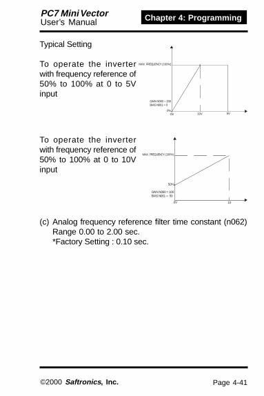
Page 4-41
Chapter 4: ProgrammingPC7 Mini VectorUser’s Manual
©2000 Saftronics , Inc.
(c) Analog frequency reference filter time constant (n062)Range 0.00 to 2.00 sec.*Factory Setting : 0.10 sec.
Typical Setting
To operate the inverterwith frequency reference of50% to 100% at 0 to 5Vinput
To operate the inverterwith frequency reference of50% to 100% at 0 to 10Vinput
MAX. FREQUENCY (100%)
0%OV 5V10V
GAIN N060 = 200BIAS N061 = 0
MAX. FREQUENCY (100%)
GAIN N060 = 100BIAS N061 = 50
50%
0V 10

Page 4-42
Chapter 4: Programming PC7 Mini VectorUser’s Manual
©2000 Saftronics , Inc.
Output frequency
Pulse
AM
AC (0V)
+
-
100%
1440 HzPulse monitor output
4.4.4 Using Analog Output (AM-AC) as a PulseTrain Signal Output (n065)
Analog output AM-AC can be used as a pulse train output(output frequency monitor).
Set n065 to 1 when using pulse train output.
n065 = 0 : Analog monitor output= 1 : Pulse monitor output (Output frequency monitor)
sretemaraP.oN emaN tinU gnitteS
egnaryrotcaFgnitteS
560n epyttuptuorotinoMnoitceles 1 1,0 0
051ngnitteS noitpircseD
0 )110n(ycneuqerf.xaM/zH04411 1xycneuqerftuptuO:F16 6xycneuqerftuptuO:F621 21xycneuqerftuptuO:F2142 42xycneuqerftuptuO:F4263 63xycneuqerftuptuO:F63
At the factory setting the pulse of 1440Hz can be outputwhen output frequency is 100%.
Pulse monitor output can be adjusted with the parametern067.
Pulse train signal can be selected by setting n150.

Page 4-43
Chapter 4: ProgrammingPC7 Mini VectorUser’s Manual
©2000 Saftronics , Inc.
Peripheral devices must be connected according to thefollowing load conditions when using pulse monitor out-put. The machine might be damaged when the conditionsare not satisfied.
Used as a sourcing output
Used as a sinking input
egatlovtuptuO)V(LRV
ecnadepmidaoLk( )Ω
V5+ k5.1 W eromroV8+ WK5.3 eromro
V8+ WK01 eromro
)V(ylppusrewoplanretxE %5+CDV21+)Am(tnerrucgnikniS sselroAm61
4.4.5 Using Frequency Meter or Ammeter (n066)
Selects to output either output fequency or output current toanalog output terminals AM-AC for monitoring.
gnitteS noitpircseD
0 ycneuqerFtuptuO1 tnerruCtuptuO2 egatloVsuBCD3 rotinoMeuqroT4 rewoPtuptuO5 ecnereferegatlovtuptuO
NOTE:
AM
AC (0V)
External power supply
Sink current
(0V)
Load Impedance
VRL
AM
AC (0V)
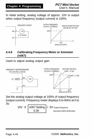
Page 4-44
Chapter 4: Programming PC7 Mini VectorUser’s Manual
©2000 Saftronics , Inc.
In initial setting, analog voltage of approx. 10V is outputwhen output frequency (output current) is 100%.
4.4.6 Calibrating Frequency Meter or Ammeter(n067)
Used to adjust analog output gain
Set the analog output voltage at 100% of output frequency(output current). Frequency meter displays 0 to 60Hz at 0 to3V.
10V X n067 Setting = 3V Output frequency
0.30 becomes 100% at this time.
AM
OUTPUT FREQUENCY(OUTPUT CURRENT)
AC0 TO 10VDC
FM
FREQUENCY METER ANALOG MONITOR GAINCAN BE SET BY N067
10VANALOG OUTPUT
0
100%
FREQUENCY METER/AMMETER(3V 1mA FULL-SCALE)
OUTPUT FREQUENCY(OUTPUT CURRENT)
FACTORY SETTING(n067 = 0.30)
-
n067
AC
AMFM
+100%
3V 10V
(n067 = 1.00)
ANALOG OUTPUT

Page 4-45
Chapter 4: ProgrammingPC7 Mini VectorUser’s Manual
©2000 Saftronics , Inc.
4.4.7 Using Multi-Function Analog Input(n077 to n079)
The input analog signal (0 to 10 V or 4 mA to 20 mA) forthe CN2 terminal of the JVOP-140 digital operator can beused as an auxiliary function for the main speed frequencyreference input to the control circuit terminals (FR or RP).Refer to the block diagram on page 4-69 for details of theinput signal.
When using the signal for the CN2 terminal of the JVOP-140 digital operator’s a multi-function analog input, neveruse it as the target value or the feedback value of PIDcontrol. (PID control is disabled when n128 is set to 0).
• n077 Multi-Function Input Selection
gnitteS gnitteS gnitteS gnitteS gnitteS emaN emaN emaN emaN emaN noitpircseD noitpircseD noitpircseD noitpircseD noitpircseD
0 delbasiD .delbasidsitupninoitcnuf-itlumehT
1 ycneuqerfyrailixuA)2FERF(ecnerefer
nidetcelessi2ecnereferycneuqerfnehWgolanatupnieht,ecnereferdeepspets-itlum
ehtsemoceblanimret2NCehtroflangisgnittes520nehT.ecnereferycneuqerf
.dilavnisemoceb
860notniagecnereferycneuqerfteS:etoNsaibecnereferycneuqerfdna,170nro
.270nro960not
2 niagecnereferycneuqerF)NIAGF( .ecnereferycneuqerfniamotniagsedivorP
3 ecnereferycneuqerF)SAIBF(
470nro060nretemarapotNIAGFehtteSrof570nro160nretemarapotSAIBFehtdna
,nehT.ecnereferycneuqerfdeepsniamehtycneuqerfgnitluserehtotSAIBFehtdda
.ecnerefertessideddaebotSAIBFehtfotnuomaehT
.970not
4 SAIBV f/VretfaegatlovtuptuoehtotSAIBVehtddA.noisrevnoc
NOTE:

Page 4-46
Chapter 4: Programming PC7 Mini VectorUser’s Manual
©2000 Saftronics , Inc.
Analog input level
• Multi-Function Analog Input Signal Selection (n078)
tnatsnoC tnatsnoC tnatsnoC tnatsnoC tnatsnoC.oN .oN .oN .oN .oN emaN emaN emaN emaN emaN tinU tinU tinU tinU tinU egnaRgnitteS egnaRgnitteS egnaRgnitteS egnaRgnitteS egnaRgnitteS yrotcaF yrotcaF yrotcaF yrotcaF yrotcaF
gnitteS gnitteS gnitteS gnitteS gnitteS
870n golananoitcnuf-itluMnoitceleslangistupni -
lanimretrotarepolatigiD=0)V01ot0:egatloV(
lanimretrotarepolatigiD=1)Am02ot4:tnerruC(
0
tnatsnoC tnatsnoC tnatsnoC tnatsnoC tnatsnoC.oN .oN .oN .oN .oN emaN emaN emaN emaN emaN tinU tinU tinU tinU tinU egnaRgnitteS egnaRgnitteS egnaRgnitteS egnaRgnitteS egnaRgnitteS yrotcaF yrotcaF yrotcaF yrotcaF yrotcaF
gnitteS gnitteS gnitteS gnitteS gnitteS
970n ecnereferycneuqerFgnittessaib %
05ot0tuptuo.xaM/%001
)110n(ycneuqerf01
• Frequency Reference Bias Setting (n079)
FREF 2
The VBIAS value to be added is doubledfor 400V class inverters.
100%
100%=Max. output frequency (n011)
10V(20mA)
0V(4mA)
0%
(1) Auxiliary frequency reference (n077 = 1)
200%
10V(20mA)
0V(4mA)
0
(2) Frequency reference gain (n077 = 2)
FGAIN
5V
1.00
FBIAS
n079
10V(20mA)
-n079
0%
(3) Frequency reference bias (n077 = 3)
VBIAS
100%
10V(20mA)
0V(4mA)
0%
(4) Output voltage bias (n077 = 4)
5V0V(4mA)

Page 4-47
Chapter 4: ProgrammingPC7 Mini VectorUser’s Manual
©2000 Saftronics , Inc.
4.5 THIRD FUNCTIONS
4.5.1 Carrier Frequency (n080)
The parameter enables the changing of the outputtransistor switching frequency (carrier frequency).
gnitteS gnitteS gnitteS gnitteS gnitteS ycneuqerFreirraC ycneuqerFreirraC ycneuqerFreirraC ycneuqerFreirraC ycneuqerFreirraC)zHk( )zHk( )zHk( )zHk( )zHk(
esioNcillateM esioNcillateM esioNcillateM esioNcillateM esioNcillateMrotoMmorf rotoMmorf rotoMmorf rotoMmorf rotoMmorf
dnaesioN dnaesioN dnaesioN dnaesioN dnaesioNegakaeLtnerruC egakaeLtnerruC egakaeLtnerruC egakaeLtnerruC egakaeLtnerruC
7 tuof21
rehgiH
elbiduAtoN
rellamS
regraL
8 tuof42
9 tuof63
1 5.2
2 0.5
3 5.7
4 0.01
Setting values 7, 8, or 9 multiplies carrier frequencyaccording to output frequency value.
n080 = 7
n080 = 8
n080 = 9
fc = Carrier Frequency
fout208.3Hz83.3Hz
1.0kHz
fc = 12 fout
2.5kHz
fc = Carrier Frequency
fout104.1Hz41.6Hz
1.0kHz
fc = 24 fout
2.5kHz
fc = Carrier Frequency
fout69.4Hz27.7Hz
1.0kHz
fc = 36 fout
2.5kHz

Page 4-48
Chapter 4: Programming PC7 Mini VectorUser’s Manual
©2000 Saftronics , Inc.
Factory setting varies according to inverter capacity (kVA).
egatloV egatloV egatloV egatloV egatloVssalC ssalC ssalC ssalC ssalC)V( )V( )V( )V( )V(
yticapaC yticapaC yticapaC yticapaC yticapaC)Wk(PH )Wk(PH )Wk(PH )Wk(PH )Wk(PH
gnitteSyrotcaF gnitteSyrotcaF gnitteSyrotcaF gnitteSyrotcaF gnitteSyrotcaF mumixaM mumixaM mumixaM mumixaM mumixaMsuounitnoC suounitnoC suounitnoC suounitnoC suounitnoC
tnerruCtuptuO tnerruCtuptuO tnerruCtuptuO tnerruCtuptuO tnerruCtuptuO*)A( *)A( *)A( *)A( *)A(
decudeR decudeR decudeR decudeR decudeRtnerruC tnerruC tnerruC tnerruC tnerruCgnitteS gnitteS gnitteS gnitteS gnitteS reirraC reirraC reirraC reirraC reirraC
ycneuqerF ycneuqerF ycneuqerF ycneuqerF ycneuqerF
002esahP-elgniS
esahP-3
)1.0(31.0 4 zHk01 8.0
-)2.0(52.0 4 zHk01 6.1
)4.0(5.0 4 zHk01 0.3)57.0(1 4 zHk01 0.5
)5.1(2 3 zHk5.7 0.8 0.7)2.2(3 3 zHk5.7 0.11 0.01)7.3(5 3 zHk5.7 5.71 5.61)5.5(5.7 3 zHk5.7 52 32)5.7(01 3 zHk5.7 33 03
004esahP-3
)2.0(5.0 3 zHk5.7 2.1 0.1)4.0(57.0 3 zHk5.7 8.1 6.1
)57.0(2 3 zHk5.7 4.3 0.3)5.1(3 3 zHk5.7 8.4 0.4)2.2(3 3 zHk5.7 5.5 8.4)0.3(3 3 zHk5.7 2.7 3.6)7.3(5 3 zHk5.7 2.9 6.7)5.5(5.7 3 zHk5.7 8.41 *)5.7(01 3 zHk5.7 81 71
*Reduction not necessary(1) Reduce continuous output current when changing carrier
frequency to 4 (10kHz) for the 200V class (1.5 kW or more)and 400V class inverters. Refer to the table above for thereduced current. [Operation Condition]
• Input power 3-phase 200 to 230V (200V class)supply voltage: Single-phase 200 to 240V (200V class)
3-phase 380 to 460V (400V class)• Ambient -10o to +50oC (Protection structure:
temperature: open chassis type IP20)
(2) If the wiring distance is long, reduce the inverter carrierfrequency as described below.
neewtebecnatsiDgniriW neewtebecnatsiDgniriW neewtebecnatsiDgniriW neewtebecnatsiDgniriW neewtebecnatsiDgniriWrotoMdnaretrevnI rotoMdnaretrevnI rotoMdnaretrevnI rotoMdnaretrevnI rotoMdnaretrevnI
.tf461otpU .tf461otpU .tf461otpU .tf461otpU .tf461otpU)m05( )m05( )m05( )m05( )m05(
.tf823otpU .tf823otpU .tf823otpU .tf823otpU .tf823otpU)m001( )m001( )m001( )m001( )m001(
.tf823nahteroM .tf823nahteroM .tf823nahteroM .tf823nahteroM .tf823nahteroM)m001( )m001( )m001( )m001( )m001(
ycneuqerFreirraC)gnittes080n(
sselrozHk01)9,8,7,4,3,2,1=080n(
sselrozHk5)9,8,7,2,1=08n(
sselrozHk5.2)9,8,7,1=080n(

Page 4-49
Chapter 4: ProgrammingPC7 Mini VectorUser’s Manual
©2000 Saftronics , Inc.
4.5.2 Auto-Restart after Momentary Power Loss(n081)
When momentary power loss occurs, operation restartsautomatically.
yrotcaF yrotcaF yrotcaF yrotcaF yrotcaFgnitteS gnitteS gnitteS gnitteS gnitteS noitpircseD noitpircseD noitpircseD noitpircseD noitpircseD
00000 tonssolrewopyratnemomretfanoitareposuounitnoC.dedivorp
*1 yratnemomnihtiwyrevocerrewopretfanoitareposuounitnoC.emiturhtedirssolrewop
*2 † tontuptuotluaf(yrevocerrewopretfanoitareposuounitnoC.)dedivorp
* Hold the operation command to continue the operation after recoveryfrom a memomentary power loss.
† When 2 is selected, operation restarts if power supply voltage reachesits normal level. No fault signal is output.
4.5.3 Continue Operation by Auto-Fault Reset(n082)
Sets the inverter to restart and reset fault detection after afault occurs. The number of self-diagnoses and retryattempts can be set at n082 up to 10. The inverter willautomatically restart after the following faults occur:
• OC (overcurrent)• OV (overvoltage)
The number of retry attempts are cleared to 0 in the fol-lowing cases:(1) If no other fault occurs within 10 minutes after retry.(2) When the fault reset signal is ON after the fault is detected.(3) Power supply is turned OFF.

Page 4-50
Chapter 4: Programming PC7 Mini VectorUser’s Manual
©2000 Saftronics , Inc.
4.5.4 Jump Frequencies (n083 to n086)
This function allows the prohibition or “jumping” of criti-cal frequencies so that the motor can operate withoutresonance caused by mechanical systems. Thisfunction is also used for dead band control. Setting thevalue to 0.00Hz disables this function.
Set prohibited frequency 1, 2 or 3 as follows:n083 n084 n085If this condition is notsatisfied, the inverterdisplays “ ERR” for oneminute and restores thedata to original settings.
>=>=
4.5.5 Elapsed Timer (n088)
yrotcaF yrotcaF yrotcaF yrotcaF yrotcaFgnitteS gnitteS gnitteS gnitteS gnitteS noitpircseD noitpircseD noitpircseD noitpircseD noitpircseD
00000 emitno-rewopretrevnI)tuptuoretrevnisierehttahtemitdespaleehtstnuoC(
1 emitgninnurretrevnI)tuptuoretrevnisierehttahtemitdespaleehtstnuoC(
Cumulative operation time setting. Inverter operating timeset with parameter n087 is accumulated by the unit of10H. Accumulation starts from the time set withparameter n088.
retemaraP retemaraP retemaraP retemaraP retemaraP.oN .oN .oN .oN .oN emaN emaN emaN emaN emaN tinU tinU tinU tinU tinU egnaRgnitteS egnaRgnitteS egnaRgnitteS egnaRgnitteS egnaRgnitteS yrotcaF yrotcaF yrotcaF yrotcaF yrotcaF
gnitteS gnitteS gnitteS gnitteS gnitteS
880n noitarepoevitalumuC H01=1 0556ot0)H00556( )H(0

Page 4-51
Chapter 4: ProgrammingPC7 Mini VectorUser’s Manual
©2000 Saftronics , Inc.
4.5.6 Applying DC Injection Braking (n089 to n091)
• DC injection braking current (n089)Sets DC injection braking current in units of 1%.(Inverter Rated Current = 100%)
• DC injection braking time at stop (n090)Sets the DC injection braking time at stopping in unitsof 0.1 second. When the setting of n090 is 0, DCinjection braking is not performed but inverter outputis shut OFF at the timing of DC injection braking start.
n016 Min.OutputFrequency
n090DC Injection Braking
Time at Stop
When coasting to a stop isspecified in stoppingmethod selection (n005),DC injection braking atstop does not operate.
• DC injection braking at start (n089, n091)Restarts a coasting motor after stopping it. Set theDC injection braking time at start in n091 in units of0.1 second. Set DC injection braking current in n089in units of 1% (inverter rated current = 100%). Whenthe setting of n091 is “0”, DC injection braking is notperformed and acceleration starts from the minimumoutput frequency.
When n089 is set to 0, ac-celeration starts from theminimum output frequencyafter the baseblocking forn091 setting time.
n016 Min.OutputFrequency
n091DC Injection Braking
Time at Start

Page 4-52
Chapter 4: Programming PC7 Mini VectorUser’s Manual
©2000 Saftronics , Inc.
4.5.7 Stall Prevention During Decel (n092)• To prevent overvoltage during deceleration the inverter
automatically extends the deceleration time accordingto the value DC Bus voltage. When using an optionalbraking resistor, set n092 to 1.
gnitteS)timiltnerruc(noitneverpllatS
noitarelecedgnirud
0 dedivorP1 )detnuomrotsisergnikarbnehw(dedivorPtoN
4.5.8 Preventing Motor From Stalling (n093)
(Current Limit) Automatically adjusts the output frequencyand output current according to the load to continueoperation without stalling the motor. • Stall prevention (current limit) level during acceleration
(n093). Sets the stall prevention (current limit) levelduring acceleration in units of 1%. (Inverter RatedCurrent = 100%)* Factory Setting : 170%
A setting of 200% disables the stall prevention (currentlimit) during acceleration. During acceleration, if the out-put current exceeds the value set for n093, accelerationstops and frequency is maintained. When the outputcurrent goes down to the value set for n093, accelerationstarts.

Page 4-53
Chapter 4: ProgrammingPC7 Mini VectorUser’s Manual
©2000 Saftronics , Inc.
In the constant horsepower area [output frequency max.voltage output frequency (n013)], the stall prevention(current limit) level during acceleration is changed by thefollowing equation.
Stall prevention (current limit) levelduring accel in constant HP area
Stall prevention (current limit) Max. voltage output frequency (n013)level during accel (n093)
=
x
4.5.9 Stall Prevention During Run (n094)
• Sets the stall prevention (current limit) level duringrunning in units of 1%.(Inverter Rated Current = 100%)* Factory Setting : 160%
A setting of 200% disables the stall prevention (currentlimit) during running.
During agreed speed if the output current exceeds thevalue set for n094, deceleration starts.
>=
Output Frequency

Page 4-54
Chapter 4: Programming PC7 Mini VectorUser’s Manual
©2000 Saftronics , Inc.
When the output current exceeds the value for n094, de-celeration continues. When the output current goes downto the value set for n094, acceleration starts, up to the setfrequency.

Page 4-55
Chapter 4: ProgrammingPC7 Mini VectorUser’s Manual
©2000 Saftronics , Inc.
RELEASEWIDTH-2HzFREQUENCY DETECTION
LEVEL [Hz] (n095)
OUTPUTFREQUENCY
FREQUENCYDETECTIONSIGNAL
ON
RELEASEWIDTH+2Hz
OUTPUTFREQUENCY
FREQUENCYDETECTIONSIGNAL
ON ON
FREQUENCYDETECTIONLEVEL [Hz](n095)
• Frequency detection 1 (output frequency frequencydetection level) (set n057, n058, or n059 to “4”)
>=
• Frequency detection 2 (output frequency frequencydetection level) (set n057, n058, or n059 to “5”)
<=
4.5.10 Frequency Detection (n095)Effective when either of output terminal functionselections n057, n058 or n059 are set to “frequencydetection” (setting: 4 or 5). “Frequency detection” turnsON when output frequency is higher or lower than thefrequency detection level (n095).

Page 4-56
Chapter 4: Programming PC7 Mini VectorUser’s Manual
©2000 Saftronics , Inc.
4.5.11 Torque Detection (n096 to n099)If an excessive load is applied to the machine, outputcurrent increases can be detected by a output alarmsignal to multi-function output terminals MA, MB, P1 andP2.
To output an overtorque detection signal, set outputterminal function selection n057 to n059 to “overtorquedetection” [Setting : 6 (NO contact) or 7 (NC contact)].
MOTOR CURRENT
n098
* Overtorque detection release width (hysterisis) is seat approx. 5% of inverter rated current.
n099n099
TIME
ONONMulti-Function Output Signal(overtorque detection signal)Temrinal MA, MB, P1, P2)
• Overtorque detection function selection 1 (n096)yrotcaF yrotcaF yrotcaF yrotcaF yrotcaFgnitteS gnitteS gnitteS gnitteS gnitteS noitpircseD noitpircseD noitpircseD noitpircseD noitpircseD
00000 .dedivorptonnoitcetedeuqrotrevO
1 retfaseunitnocnoitarepodna,gninnurdeeps-tnatsnocgniruddetceteD.noitceted
2 gnirudspotsnoitarepodna,gninnurdeeps-tnatsnocgniruddetceteD.noitceted
3 .noitcetedretfaseunitnocnoitarepodna,gninnurgniruddetceteD4 .noitcetedgnirudspotsnoitarepodna,gninnurgniruddetceteD
(1) To detect overtorque at accel/decel, set to 3 or 4.(2) To continue the operation after an overtorque detec-
tion, set to 1 or 3. During detection, the operatordisplays “ 00000L3L3L3L3L3” alarm (blinking).
(3) To halt the inverter by a fault at overtorque detection, setto 2 or 4. At detection, the operator displays “ 00000L3L3L3L3L3” fault(ON).

Page 4-57
Chapter 4: ProgrammingPC7 Mini VectorUser’s Manual
©2000 Saftronics , Inc.
• Overtorque detection level (n098)Sets the overtorque detection current level in units of1%. (Inverter Rated Current = 100%)*Factory Setting: 160%
• Overtorque detection time (n099)When motor current exceeds the overtorque detectionlevel (n098) is longer than overtorque detection time(n099), the overtorque detection function operates.*Factory Setting: 0.1 sec.
• Overtorque detection function selection 2 (n097)When vector control mode is selected, overtorquedetection can be performed either by output current orby output torque.When V/f control mode is selected, n097 settingbecomes invalid, and overtorque is detected by outputcurrent.
yrotcaFgnitteS noitpircseD
0 euqrottuptuoybdetceteD
1 tnerructuptuoybdetceteD

Page 4-58
Chapter 4: Programming PC7 Mini VectorUser’s Manual
©2000 Saftronics , Inc.
4.5.12 Timing Chart UP/DOWN Command Input(n100)
• UP/DOWN command (setting: n056 = 034)With the FWD (REV) run command entered, accel/decelis enabled by inputting the UP or DOWN signals tomulti-function input terminals S6 and S7 withoutchanging the frequency reference, so that operationcan be performed at the desired speed. When UP/DOWN commands are specified by n056, any functionset to n055 becomes disabled; terminal S6 becomesan input terminal for the UP command and terminal S7for the DOWN command.
6SlanimreTtupnInoitcnuF-itluM)dnammoCpU( desolC nepO nepO desolC
7SlanimreTtupnInoitcnuF-itluM)dnammoCNWOD( nepO desolC nepO desolC
sutatSnoitarepO leccA leceD dloH dloH
U = UP (accelerating) statusD = DOWN (decelerating) statusH = HOLD (constant speed) statusU1 = UP status, clamping at upper limit speedD1 = DOWN status, clamping at lower limit speed
FREQUENCY AGREEDSIGNAL
FWD RUN
LOWER LIMIT SPEEDOUTPUT FREQUENCY
UPPER LIMIT SPEED
DOWN COMMAND S7
UP COMMAND S6
D1H U H D H U H D D1 H U U1 H D D1 H

Page 4-59
Chapter 4: ProgrammingPC7 Mini VectorUser’s Manual
©2000 Saftronics , Inc.
NOTE:
1. When UP/DOWN command is selected, the upperlimit speed is set regardless of frequency reference.
Upper limit speed = Maximum output frequency (n013)x Frequency reference upper limit (n033)/100
2. Lower limit value is either minimum output frequency(n016) or frequency reference lower limit (n034)(whichever is larger).
3. When the FWD (REV) run command is input, operationstarts at the lower limit speed without an UP/DOWNcommand.
4. If the jog command is input while running by the UP/DOWN command, the jog command has priority.
5. Multi-step speed reference 1 to 4 is not effective whenUP/DOWN command is selected. Multi-step speedreference is effective during running in hold status.
6. Output frequency is retained when hold referencememory selection (n100) is set to 1.
yrotcaF yrotcaF yrotcaF yrotcaF yrotcaFgnitteS gnitteS gnitteS gnitteS gnitteS noitpircseD noitpircseD noitpircseD noitpircseD noitpircseD
00000 .delbasiD
1 dna,deniatersisutatsdlohniycneuqerftuptuO.delbanE.ecnereferycneuqerfehttaegappotsnoitareporetfadetratser
n100 Settings

Page 4-60
Chapter 4: Programming PC7 Mini VectorUser’s Manual
©2000 Saftronics , Inc.
Time Chart at Accel/Decel hold command input
REQUENCYREFERENCE
ACCEL/DECELHOLD COMMAND
FWD (REV)RUN COMMAND
ONON
ONON
ON
ON
FREQUENCYAGREEDSIGNAL
OUTPUTFREQUENCY
When the FWD (REV) run command is input along withthe accel/decel hold command, the motor does notoperate. However, when frequency reference lower limit(n034) is set greater than or equal to minimum outputfrequency (n016), the motor operates at frequencyreference lower limit (n034).
NOTE:
To hold acceleration or deceleration, input accel/decelhold command. The output frequency is maintained whenthe accel/decel hold command is input during accelera-tion or deceleration.
The stop command releases the accel/decel hold andthe operation ramps to stop.
Set multi-function input terminal selection (n052 to n056)to 16 (accel/decel hold command).
4.5.13 Holding Accel/Decel Temporarily

Page 4-61
Chapter 4: ProgrammingPC7 Mini VectorUser’s Manual
©2000 Saftronics , Inc.
4.5.14 Stall Prevention During Operation (n115)
• Stall prevention automatic decrease selection (n115)The stall prevention level can be increased automati-cally in the parameter output range.
.oNretemaraP .oNretemaraP .oNretemaraP .oNretemaraP .oNretemaraP emaN emaN emaN emaN emaN tinU tinU tinU tinU tinU egnaRgnitteS egnaRgnitteS egnaRgnitteS egnaRgnitteS egnaRgnitteS gnitteSyrotcaF gnitteSyrotcaF gnitteSyrotcaF gnitteSyrotcaF gnitteSyrotcaF
511nnoitneverpllatS
esaercedcitamotuanoitceles
- delbasiD=0delbanE=1 0
gnitteS gnitteS gnitteS gnitteS gnitteS noitcnuF noitcnuF noitcnuF noitcnuF noitcnuF
0 ehtrofteslevelehtsemoceblevelnoitneverpllatsehT.saeraycneuqerfllani490nretemarap
1
silevelnoitneverpllatsehttahtswohsgniwollofehTegnartuptuoretemarapehtnidesaercedyllacitamotua
.)ycneuqerftuptuoegatlov.xaM>ycneuqerf.xaM(.490nfoeulavtesehtfo%04sitimilrewolehT
Refer to page 4-18 for n103Refer to page 4-13 for n104 and n105Refer to page 4-12 for n106, n107 and n110Refer to page 4-13 for n111 and n112
n013
40% of n094
n094
Operation level Operation level =
Constant output area
n094 x max. voltage output frequency n013output frequency
Lower limit
Output frequency

Page 4-62
Chapter 4: Programming PC7 Mini VectorUser’s Manual
©2000 Saftronics , Inc.
With this function, acceleration/deceleration time whenmoving to prevent stalling during operations can beassigned to the two parameters, n021 and n022.
4.5.15 Accel/Decel Time Selection During StallPrevention (n116)
retemaraP retemaraP retemaraP retemaraP retemaraP.oN .oN .oN .oN .oN emaN emaN emaN emaN emaN tinU tinU tinU tinU tinU egnaRgnitteS egnaRgnitteS egnaRgnitteS egnaRgnitteS egnaRgnitteS yrotcaF yrotcaF yrotcaF yrotcaF yrotcaF
gnitteS gnitteS gnitteS gnitteS gnitteS
611nemitleced/leccAgnirudnoitceles
noitneverpllats- delbasiD=0
delbanE=1 0
yrotcaF yrotcaF yrotcaF yrotcaF yrotcaFgnitteS gnitteS gnitteS gnitteS gnitteS noitcnuF noitcnuF noitcnuF noitcnuF noitcnuF
0 .2ro1emitleced/leccaybtessiemitleced/leccA
1 ,120n(2emitleced/leccatadexifsiemitleced/leccA.)220n

Page 4-63
Chapter 4: ProgrammingPC7 Mini VectorUser’s Manual
©2000 Saftronics , Inc.
gnitteS gnitteS gnitteS gnitteS gnitteS noitcnuF noitcnuF noitcnuF noitcnuF noitcnuF tuptuODIP tuptuODIP tuptuODIP tuptuODIP tuptuODIPscitsiretcarahC scitsiretcarahC scitsiretcarahC scitsiretcarahC scitsiretcarahC
0 delbasiD
drawroF
1 lortnoclaitnereffidottcejbussinoitaived:delbanE2 lortnoclaitnereffidottcejbussilangiskcabdeef:delbanE
3 eranoitaiveddna,lortnocDIP+ecnereferycneuqerf:delbanElortnoclaitnereffidottcejbus
4 langiskcabdeefdna,lortnocDIP+ecnereferycneuqerf:delbanElortnoclaitnereffidottcejbusera
5 lortnoclaitnereffidottcejbussinoitaived:delbanE
esreveR
6 lortnoclaitnereffidottcejbussilangiskcabdeef:delbanE
7 eranoitaiveddna,lortnocDIP+ecnereferycneuqerf:delbanElortnoclaitnereffidottcejbus
8 langiskcabdeefdnalortnocDIP+ecnereferycneuqerf:delbanElortnoclaitnereffidottcejbusera
4.6.1 Using PID Control Mode (n128 to n138)
For details of the PID control setting, refer to the blockdiagram (page 4-69) of the Inverter’s internal PID control orthe block diagram of the operator analog speed reference.Refer to Appendix B for additional information on the setupof PID.
4.6 FOURTH FUNCTION (n120 to n179)
.oNretemaraP .oNretemaraP .oNretemaraP .oNretemaraP .oNretemaraP emaN emaN emaN emaN emaN tinU tinU tinU tinU tinU egnaRgnitteS egnaRgnitteS egnaRgnitteS egnaRgnitteS egnaRgnitteS gnitteSyrotcaF gnitteSyrotcaF gnitteSyrotcaF gnitteSyrotcaF gnitteSyrotcaF
821n lortnocDIPnoitceles - 8ot0 0
n128 Settings
Set one of the above values when using PID control.gnitteS461n gnitteS461n gnitteS461n gnitteS461n gnitteS461n noitpircseD noitpircseD noitpircseD noitpircseD noitpircseD
0 )V01ot0egatloV(RFlanimrettiucriclortnoC1 )Am02ot4tnerruC(lanimrettiucriclortnoC2 )Am02ot0tnerruC(lanimrettiucriclortnoC3 )2NC()V01ot0egatloV(lanimretrotarepO4 )2NC()Am02ot4tnerruC(lanimretrotarepO5 niartesluP
Refer to page 4-29 for n120 to n127

Page 4-64
Chapter 4: Programming PC7 Mini VectorUser’s Manual
©2000 Saftronics , Inc.
The following table shows how to determine the targetvalue and the feedback value to be input when the PIDcontrol is enabled.
tupnI tupnI tupnI tupnI tupnI noitidnoC noitidnoC noitidnoC noitidnoC noitidnoC
tegraTeulaV
ycneuqerfdetcelesyltnerrucehTecnerefer
.)400n(noitcelesecnereferycneuqerfehtybdenimreteDsieulavtegrateht,detcelessiedomlacolehtnehWlacolninoitcelesecnereferycneuqerfybdenimreted
.)800n(edomeht,detcelessiecnereferdeepspets-itlumehtnehW
ehtsemocebecnereferycneuqerfdetcelesyltnerruc.eulavtegrat
kcabdeeFeulaV
tessitahtecnereferycneuqerfehTnoitceleseulavkcabdeefDIPehtot
)461n(-
1. When selecting frequency reference from the controlcircuit terminal FR as the target or feedback value, theV-I switch of SW2 on the control circuit board must beselected depending on the input method (current orvoltage input).
2. Never use the frequency reference from the controlcircuit terminal FR for both the target and feedbackvalues. The frequency reference for both the target valueand the feedback value becomes the same.
Example: When the frequency reference from the controlcircuit terminal FR, with a voltage of 0 to 10 V, is selected asthe target value and n004 = 2, and at the same time thefrequency reference from the control circuit terminal FR,with a current of 4 to 20 mA, is selected as the fedbackvalue and n164 = 1, the feedback value will be set as thefrequency reference from the control circuit terminal Fr.
3. When using the analog signal (0 to 10 V / 4 to 20 mA)which inputs to the CN2 terminal of the digital operatorJVOP-140 as the target or feedback value of PIDcontrol, never use it as a multi-analog input. Parametern077 (multi-function analog input) should be setto 0 (disabled).
NOTE:

Page 4-65
Chapter 4: ProgrammingPC7 Mini VectorUser’s Manual
©2000 Saftronics , Inc.
• Proportional gain (P), Integral Time (I),Differential Time (D) (n130, n131, n132)
Adjust the response of the PID control with the proportionalgain (P), integral time (I), and differential time (D).
.oNretemaraP .oNretemaraP .oNretemaraP .oNretemaraP .oNretemaraP emaN emaN emaN emaN emaN tinU tinU tinU tinU tinU egnaRgnitteS egnaRgnitteS egnaRgnitteS egnaRgnitteS egnaRgnitteS gnitteSyrotcaF gnitteSyrotcaF gnitteSyrotcaF gnitteSyrotcaF gnitteSyrotcaF031n )P(niaglanoitroproP selpitluM 0.52ot0.0 0.1131n )I(emiTlargetnI s0.1 0.063ot0.0 0.1231n )D(emiTlaitnereffiD s0.1 05.2ot00.0 00.0
Optimize the responsiveness by adjusting it while operat-ing an actual load (mechanical system). Any control (P, I, orD) that is set to zero (0.0, 0.00) will not operate.
• PID Proportional Gain (n130)Proportional gain is the value by which the error signal ismultiplied to generate a new PID controller output. A highersetting will result in a more responsive system. A lowersetting will result in a more stable system.
.oNretemaraP .oNretemaraP .oNretemaraP .oNretemaraP .oNretemaraP emaN emaN emaN emaN emaN tinU tinU tinU tinU tinU egnaRgnitteS egnaRgnitteS egnaRgnitteS egnaRgnitteS egnaRgnitteS gnitteSyrotcaF gnitteSyrotcaF gnitteSyrotcaF gnitteSyrotcaF gnitteSyrotcaF031n niaGlanoitroporPDIP - 00.01ot00.0 0.1
• PID Integral Time (n131)This parameter determines how fast the PID controller willseek to eliminate any steady-state error. The lower thesetting, the faster the error will be eliminated. To eliminatethe integral function entirely, set this parameter to 0.0seconds. A lower setting will result in a more responsivesystem. A higher setting will result in a more stablesystem.
.oNretemaraP .oNretemaraP .oNretemaraP .oNretemaraP .oNretemaraP emaN emaN emaN emaN emaN tinU tinU tinU tinU tinU egnaRgnitteS egnaRgnitteS egnaRgnitteS egnaRgnitteS egnaRgnitteS gnitteSyrotcaF gnitteSyrotcaF gnitteSyrotcaF gnitteSyrotcaF gnitteSyrotcaF131n emiTlargetnIDIP .ces 0.063ot00.0 0.1
retemaraP retemaraP retemaraP retemaraP retemaraP.oN .oN .oN .oN .oN emaN emaN emaN emaN emaN tinU tinU tinU tinU tinU egnaRgnitteS egnaRgnitteS egnaRgnitteS egnaRgnitteS egnaRgnitteS gnitteSyrotcaF gnitteSyrotcaF gnitteSyrotcaF gnitteSyrotcaF gnitteSyrotcaF
921n niaggnitsujdaeulavkcabdeefDIP selpitluM 0.01ot0.0 0.1
• PID Feedback Value Adjusting Gain (n129)Parameter n129 is the gain that adjusts the feedback value.

Page 4-66
Chapter 4: Programming PC7 Mini VectorUser’s Manual
©2000 Saftronics , Inc.
.oNretemaraP .oNretemaraP .oNretemaraP .oNretemaraP .oNretemaraP emaN emaN emaN emaN emaN tinU tinU tinU tinU tinU egnaRgnitteS egnaRgnitteS egnaRgnitteS egnaRgnitteS egnaRgnitteS gnitteSyrotcaF gnitteSyrotcaF gnitteSyrotcaF gnitteSyrotcaF gnitteSyrotcaF431n timiL)I(largetnI % 001ot0 001
• PID Offset Adjustment (n133)Parameter n133 adjusts the PID control offset.If both the target value and the feedback values are set tozero, adjust the inverter output frequency to zero.
.oNretemaraP .oNretemaraP .oNretemaraP .oNretemaraP .oNretemaraP emaN emaN emaN emaN emaN tinU tinU tinU tinU tinU egnaRgnitteS egnaRgnitteS egnaRgnitteS egnaRgnitteS egnaRgnitteS gnitteSyrotcaF gnitteSyrotcaF gnitteSyrotcaF gnitteSyrotcaF gnitteSyrotcaF331n tnemtsujdAtesffODIP % 001ot001- 0
• Integral (I) Limit (n134)This parameter prevents the calculated value of theintegral control from exceeding the fixed amount. Thereis normally no need to change the setting.Reduce the setting if there is a risk of load damage, or ofthe motor going out of step by the inverter’s responsewhen the load suddenly changes. If the setting isreduced too much, the target value and the feedback valuewill not match.Set this parameter as a percentage of the maximumoutput frequency with the maximum frequency as 100%.
• Derivative Time (n132)This parameter can be adjusted to increase systemresponse to fast load or reference changes, and to reduceovershoot upon startup. To eliminate the differentialfunction entirely, set this parameter to 0.00 seconds.
.oNretemaraP .oNretemaraP .oNretemaraP .oNretemaraP .oNretemaraP emaN emaN emaN emaN emaN tinU tinU tinU tinU tinU egnaRgnitteS egnaRgnitteS egnaRgnitteS egnaRgnitteS egnaRgnitteS gnitteSyrotcaF gnitteSyrotcaF gnitteSyrotcaF gnitteSyrotcaF gnitteSyrotcaF231n emiTevitavireD .ces 0.01ot00.0 00.0

Page 4-67
Chapter 4: ProgrammingPC7 Mini VectorUser’s Manual
©2000 Saftronics , Inc.
• PID Primary Delay Time Parameter (n135)retemaraP retemaraP retemaraP retemaraP retemaraP
.oN .oN .oN .oN .oN emaN emaN emaN emaN emaN tinU tinU tinU tinU tinU egnaRgnitteS egnaRgnitteS egnaRgnitteS egnaRgnitteS egnaRgnitteS gnitteSyrotcaF gnitteSyrotcaF gnitteSyrotcaF gnitteSyrotcaF gnitteSyrotcaF
531n retemarapemityaledyramirpDIP sdnoceS 001ot0.0 0.0
• PID Output Gain (n163)retemaraP retemaraP retemaraP retemaraP retemaraP
.oN .oN .oN .oN .oN emaN emaN emaN emaN emaN tinU tinU tinU tinU tinU egnaRgnitteS egnaRgnitteS egnaRgnitteS egnaRgnitteS egnaRgnitteS gnitteSyrotcaF gnitteSyrotcaF gnitteSyrotcaF gnitteSyrotcaF gnitteSyrotcaF
361n niaGtuptuODIP selpitluM 0.52ot0.0 0.1
retemaraP retemaraP retemaraP retemaraP retemaraP.oN .oN .oN .oN .oN emaN emaN emaN emaN emaN tinU tinU tinU tinU tinU egnaRgnitteS egnaRgnitteS egnaRgnitteS egnaRgnitteS egnaRgnitteS gnitteSyrotcaF gnitteSyrotcaF gnitteSyrotcaF gnitteSyrotcaF gnitteSyrotcaF
631nDIPfonoitceleS
ssolkcabdeefnoitceted
-
ssolkcabdeefDIPfonoitcetedoN:0ssolkcabdeefDIPfonoitceteD:1)mralaLbF:deunitnocnoitarepo(ssolkcabdeefDIPfonoitceteD:2
)tluaf:nwodtuhstuptuo(
0
731n ssolkcabdeefDIPlevelnoitceted % tuptuo.xaM/%001001ot0
ycneuqerf 0
831n ssolkcabdeefDIPemitnoitceted % 5.52ot0.0 0.1
• PID LimitSets the limite after PID control as a percentage of themaximum output frequency.
• Prohibition of PID outputThe output frequency is limited to zero Hz even if the PIDcalculature yields a negative number (The motor will not“back up”).
Parameter n135 is the low-pass filter setting for PIDcontrol outputs. If the friction of the mechanical system istoo high, or if the rigidity is too low, the system can oscillate.Increasing this parameter will dampen those oscillations.
This parameter adjusts the output gain.
• PID Feedback Loss Detection (n136, n137, n138)

Page 4-68
Chapter 4: Programming PC7 Mini VectorUser’s Manual
©2000 Saftronics , Inc.
n004
Ope
rato
r P
oten
tiom
eter
FR
EF
1 (
n024
)
Ext
erna
l Ter
min
al (
0 to
10
V)
Ext
erna
l Ter
min
al (
4 to
20
mA
)E
xter
nal T
erm
inal
(0
to 2
0 m
A)
Pul
se T
rain
Com
mun
icat
ion
Ope
rato
r (0
to 1
0 V
)O
pera
tor
(4 to
20
mA
)
Ope
rato
r P
oten
tiom
eter
FR
EF
1 (
n024
)Rem
ote
/ Loc
al
Mul
ti-S
tep
Spe
ed R
efer
ence
Freq
ency
Ref
eren
ce S
elec
tion
FR
EF
2 (
n025
)F
RE
F 3
(n0
26)
FR
EF
4 (
n027
)F
RE
F 5
(n0
28)
FR
EF
6 (
n029
)F
RE
F 7
(n0
30)
FR
EF
8 (
n031
)F
RE
F 9
(n1
20)
FR
EF
10
(n12
1)F
RE
F 1
1 (n
122)
FR
EF
12
(n12
3)F
RE
F 1
3 (n
124)
FR
EF
14
(n12
5)F
RE
F 1
5 (n
126)
FR
EF
16
(n12
7)F
JO
G (
n032
)
n164
Ext
erna
l Ter
min
al (
0 to
10
V)
Ext
erna
l Ter
min
al (
4 to
20
mA
)E
xter
nal T
erm
inal
(0
to 2
0 m
A)
Ope
rato
r (0
to 1
0 V
)O
pera
tor
(4 to
20
mA
)P
ulse
Tra
inA
djus
tmen
t Gai
n
n129
100%
Z-1
n132
Diff
eren
tial T
ime
(D)
+ + n128
= 2
, 4, 6
, 8
PID
Con
trol
Sel
ectio
nn1
28 =
1, 3
, 5, 7
Fee
dbac
k V
alue
MN
TR
(U
-16)
100%
/ F
MA
X
NO
TE
S:
Z-1
can
not b
e cl
eare
d du
ring
oper
atio
n co
mm
and
inpu
t.Z
-1 c
an b
e cl
eare
d du
ring
stop
com
man
d in
put,
or d
urin
g P
ID c
ance
l by
the
mul
ti-fu
nctio
n in
put.
PID
Inpu
tM
NT
R (
U-1
7)10
0% /
FM
AX
+
- Pro
port
iona
lG
ain
n130
1n1
31
Inte
gral
Tim
e(I
)co
mpe
nsat
ion
with
rem
inde
r
Z-1
n132
Z-1
Diff
eren
tial
(D) T
ime
PID
con
trol
sel
ectio
nn1
28 =
2, 4
, 6 ,8
n128
= 1
, 3, 5
, 7In
tegr
al li
mit
from
mul
ti-fu
nctio
n in
put
-n13
4
n134
Inte
gral
lim
it fr
omm
ulti-
func
tion
inpu
t
Inte
gral
upp
erlim
it
Z-1
+ ++
-100
%
100%
+ -1
n135
PID
prim
ary
dela
y tim
eco
nsta
nt c
ompe
nsat
ion
with
rem
inde
r
Z-1
PID
con
trol
sel
ectio
nn1
28 =
1, 2
, 3, 4
x 1
x -1
n128
= 5
, 6, 7
, 8 PID
offs
et a
djus
tmen
tn1
33
n163
PID
out
put g
ain
+ +
-200
%
200%
PID
out
put v
alue
MN
TR
(U
-18)
10%
/ F
MA
X
n128
= 1
, 2, 5
, 6P
ID c
ontr
ol s
elec
tion
n128
= 3
, 4, 7
, 8
n128
= 0
or
PID
can
cel b
y th
em
ulti-
func
tion
inpu
t 00
110%
Out
put F
requ
ency
PID
Con
trol
Blo
ck D
iagr
am

Page 4-69
Chapter 4: ProgrammingPC7 Mini VectorUser’s Manual
©2000 Saftronics , Inc.
Dig
ital O
pera
tor
(JV
OP
-140
)
RS
-232
C M
OD
BU
S C
omm
unic
atio
n
(960
0 bp
s)
A/D
conv
ersi
on
0 -
10 V
VIN
Pin
1of
CN
2
RS
-232
C M
OD
BU
S C
omm
unic
atio
n
(960
0 bp
s)
A/D
conv
ersi
on
4 -
20 m
AIIN
Pin
2of
CN
2
GN
DP
in 3
of C
N 2
A/D
con
vert
er G
ND
OV
AD
CH
2
Max
. out
put f
requ
ency
n011
3FF
H1
n073
+ ++ -
Z-1
n072
Bia
sw
ith c
ompe
nsat
ion
+
+
I n07
1 I
Gai
n
n071
0
> = -
+
n011
Max
. out
put f
requ
ency
n071
< 0
0%
110%
Fref
Con
vert
s A
/D (
valu
e) in
to H
zP
rimar
y de
lay
time
cons
tant
Max
. out
put f
requ
ency
n011
3FF
H1
n070
+ ++ -
Z-1
n069
Bia
sC
ompe
nsat
ion
with
rem
inde
r
+
+
I n06
8 I
Gai
n
n068
0
> = -
+
n011
Max
. out
put f
requ
ency
n068
< 0
0%
110%
Fref
Con
vert
s A
/D (
valu
e) in
to H
zP
rimar
y de
lay
time
cons
tant
INV
ER
TE
R
Ope
rato
r A
nalo
g S
peed
Ref
eren
ce B
lock
Dia
gram
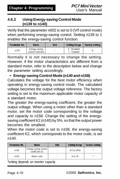
Page 4-70
Chapter 4: Programming PC7 Mini VectorUser’s Manual
©2000 Saftronics , Inc.
Verify that the parameter n002 is set to 0 (V/f control mode)when performing energy-saving control. Setting n139 to 1enables the energy-saving control function.
Normally it is not necessary to change the setting.However, if the motor characteristics are different from astandard motor, refer to the description below and changethe parameter setting accordingly.
• Energy-saving Control Mode (n140 and n158)Calculates the voltage for the best motor efficiency whenoperating in energy-saving control mode. The calculatedvoltage becomes the output voltage reference. The factorysetting is set to the maximum applicable motor capacity ofa standard motor.The greater the energy-saving coefficient, the greater theoutput voltage. When using a motor other than a standardmotor, set the motor code corresponding to the voltageand capacity to n158. Change the setting of the energy-saving coefficient K2 (n140) by 5%, so that the output powerbecomes the smallest.When the motor code is set to n158, the energy-savingcoefficient K2, which corresponds to the motor code, is setn140.
.oNretemaraP .oNretemaraP .oNretemaraP .oNretemaraP .oNretemaraP emaN emaN emaN emaN emaN tinU tinU tinU tinU tinU egnaRgnitteS egnaRgnitteS egnaRgnitteS egnaRgnitteS egnaRgnitteS gnitteSyrotcaF gnitteSyrotcaF gnitteSyrotcaF gnitteSyrotcaF gnitteSyrotcaF
931n gnivas-ygrenEnoitceleslortnoc - delbasiD:0
delbanE:1 0
.oNretemaraP .oNretemaraP .oNretemaraP .oNretemaraP .oNretemaraP emaN emaN emaN emaN emaN tinU tinU tinU tinU tinU egnaRgnitteS egnaRgnitteS egnaRgnitteS egnaRgnitteS egnaRgnitteS gnitteSyrotcaF gnitteSyrotcaF gnitteSyrotcaF gnitteSyrotcaF gnitteSyrotcaF
041n lortnocgnivas-ygrenE2Ktneiciffeoc - 0556ot0.0 *
851n edocrotoM - 07ot0 *
*setting depends on inverter capacity
4.6.2 Using Energy-saving Control Mode(n139 to n140)

Page 4-71
Chapter 4: ProgrammingPC7 Mini VectorUser’s Manual
©2000 Saftronics , Inc.
The energy-saving coefficient K2 (n140) is set to a valuethat corresponds with that motor code (n158).
epyTrotoM epyTrotoM epyTrotoM epyTrotoM epyTrotoM ssalCegatloV ssalCegatloV ssalCegatloV ssalCegatloV ssalCegatloV yticapaC yticapaC yticapaC yticapaC yticapaC :edoCrotoM :edoCrotoM :edoCrotoM :edoCrotoM :edoCrotoM851n 851n 851n 851n 851n
gnivaS-ygrenE gnivaS-ygrenE gnivaS-ygrenE gnivaS-ygrenE gnivaS-ygrenE041n:2Ktneiciffeoc 041n:2Ktneiciffeoc 041n:2Ktneiciffeoc 041n:2Ktneiciffeoc 041n:2Ktneiciffeoc
lareneGlacipyTrotoMesopruP
V002
Wk1.0 0 7.184Wk2.0 1 9.653Wk4.0 2 2.882Wk57.0 3 7.322Wk5.1 4 4.961Wk2.2 5 8.651Wk7.3 7 9.221Wk5.5 9 8.49Wk5.7 01 7.27
V004
Wk2.0 12 8.317Wk4.0 22 4.675Wk57.0 32 4.744Wk5.1 42 8.833Wk2.2 52 6.313Wk0.3 62 8.542Wk7.3 72 8.542Wk5.5 92 5.981Wk5.7 03 4.541
retrevnIlacipyTrotoM
V002
Wk1.0 04 7.184Wk2.0 14 9.653Wk4.0 24 9.003Wk57.0 34 7.422Wk5.1 44 4.061Wk2.2 54 9.831Wk7.3 74 9.601Wk5.5 94 1.48Wk5.7 05 7.17
V004
Wk2.0 16 8.317Wk4.0 26 8.106Wk57.0 36 4.944Wk5.1 46 8.023Wk2.2 56 8.772Wk0.3 66 8.312Wk7.3 76 8.312Wk5.5 96 3.861Wk5.7 07 3.341

Page 4-72
Chapter 4: Programming PC7 Mini VectorUser’s Manual
©2000 Saftronics , Inc.
• Energy-saving voltage lower/upper limit(n141, n142, n159, n160)
Sets the upper and lower limits of the output voltage. Whenthe value calculated in the energy-saving control mode islarger than the upper limit (or smaller than the lower limit),the value is output as a voltage reference value. The upperlimit is set to prevent over-excitation, and the lower limit isset to prevent stalls when the load is light. The voltage limitis set for machines using 6Hz/60Hz. For any voltage otherthan 6Hz/60Hz, set the (value of the) voltage limit accordingto linear interpolation. The parameters are set in % for200V/400V inverters.
.oNretemaraP .oNretemaraP .oNretemaraP .oNretemaraP .oNretemaraP emaN emaN emaN emaN emaN tinU tinU tinU tinU tinU egnaRgnitteS egnaRgnitteS egnaRgnitteS egnaRgnitteS egnaRgnitteS gnitteSyrotcaF gnitteSyrotcaF gnitteSyrotcaF gnitteSyrotcaF gnitteSyrotcaF
141n egatlovgnivas-ygrenE)zH06(timilrewol % 021ot0 05
241n egatlovgnivas-ygrenE)zH6(timilrewol % 52ot0 21
951n egatlovgnivas-ygrenE)zH06(timilreppu % 021ot0 021
061n egatlovgnivas-ygrenE)zH6(timilreppu % 52ot0 61
n142n160
n141
n159250V *
Voltage limit
6Hz
Upper limit
Lower limit
Output frequency60 Hz
*Doubled for the 400V class inverters.

Page 4-73
Chapter 4: ProgrammingPC7 Mini VectorUser’s Manual
©2000 Saftronics , Inc.
In the energy control mode, the maximum applicablevoltage is calculated using the output power. However, atemperature change will change the fixed parameters, andthe maximum applicable voltage may not be emitted. In thesearch operation, change the voltage slightly so that themaximum appliable voltage can be obtained.
• Search Operation Voltage Limit (n144)Limits the range where the voltage can be controlled. Theparameters are set in % for 200V/400V inverters. The searchoperation is not performed when set to ).
.oNretemaraP .oNretemaraP .oNretemaraP .oNretemaraP .oNretemaraP emaN emaN emaN emaN emaN tinU tinU tinU tinU tinU egnaRgnitteS egnaRgnitteS egnaRgnitteS egnaRgnitteS egnaRgnitteS gnitteSyrotcaF gnitteSyrotcaF gnitteSyrotcaF gnitteSyrotcaF gnitteSyrotcaF
441n noitarepohcraeStimilegatlov % 001ot0 0
.oNretemaraP .oNretemaraP .oNretemaraP .oNretemaraP .oNretemaraP emaN emaN emaN emaN emaN tinU tinU tinU tinU tinU egnaRgnitteS egnaRgnitteS egnaRgnitteS egnaRgnitteS egnaRgnitteS gnitteSyrotcaF gnitteSyrotcaF gnitteSyrotcaF gnitteSyrotcaF gnitteSyrotcaF
541n noitarepohcraeS)%001(petsegatlov % 0.01ot1.0 5.0
641n noitarepohcraeS)%001(petsegatlov % 0.01ot1.0 2.0
341n noitarepohcraeSelcyclortnoc sm42x 0002ot1 )sm42(1
• Search Operation Voltage Step (n145, n146)Sets the voltage fluctuations for one cycle of the searchoperation. Increase the value and the fluctuation of therotation speed will also increase. The value calculated bylinear interpolation is set for voltage other than above.
n146
n145
10%
Voltage fluctuation
5% 100%

Page 4-74
Chapter 4: Programming PC7 Mini VectorUser’s Manual
©2000 Saftronics , Inc.
4.6.3 Frequency Command by Pulse Train Input(n149)
Frequency reference can be set by pulse train input fromthe multi-function input terminal (RP).
• Input pulse specifications- Low-level voltage : 0.8 or less- High-level voltage : 3.5 to 13.2 V- H duty : 30 to 70%- Pulse frequency : 0 to 30 kHz
• Frequency reference methodFrequency reference is a value obtained by multiplying theratio of the maximum input pulse frequency and acutalinput pulse frequency by the maximum output frequency.
IM
FORWARD RUN/STOPRun/Stop and FWD/REV canbe selected by a switchconnected to the controlcircuit terminal.
Frequency setting can beset by pulse train inputsignal [0 to 100% (maximumfrequency)/0 to 30kHz]connected to the multi-function input terminal.
FC
RP
SCS2S1
PULSEREFERENCEDEVICE
REVERSE RUN/STOP
Reference Frequency(n011) = x Maximum Output Frequency
Maximum Pulse Train Frequency (n149)
Input Pulse Frequency

Page 4-75
Chapter 4: ProgrammingPC7 Mini VectorUser’s Manual
©2000 Saftronics , Inc.
.oN .oN .oN .oN .oN emaN emaN emaN emaN emaN gnitteS gnitteS gnitteS gnitteS gnitteS yrotcaF yrotcaF yrotcaF yrotcaF yrotcaFgnitteS gnitteS gnitteS gnitteS gnitteS
300n noitcelesdnammocnuR 1 0
400n noitcelesecnereferycneuqerF 5 0
941n zH01=1gnilacstupniniartesluP 0003)zHk03(
0052)zHk52(
4.6.4 Using MODBUS Communications(n151 to n157)
Serial transmission is available with the PC7 via MODBUSprotocol.
• MODBUS CommunicationsA MODBUS system is composed of a single master (PLC)and some number of slaves (1 to 31 PC7 units).Communication between the master and the slave(s)(serial communication) is controlled by the masterprogram with the master initiating communication andthe slave responding to those requests.The master sends a signal to one slave at a time. Eachslave has a pre-registered address number. The masterspecifies the address number along with the transmitteddata communication. The slave receives the communi-cations to carry out designated functions and reply to themaster.
ecafretnI 584SR,224-SR
noitazinorhcnyS )noitazinorhcnyspotS-tratS(suonorhcnysA
noitacinummoCsretemaraP
00291/0069/0084/0042morfdetceleS:etarduaBspb
dexiftib8:htgnelataDenon/ddo/nevemorfdetceleS:ytiraP
dexiftib1:stibpotSlocotorpnoitacinummoC )ylnoedomUTR(SUBDOMsretrevniforebmun.xaM
detcennocebnactaht )584-SRgnisunehw(stinu13
Refer to Page 4-43 for n150.
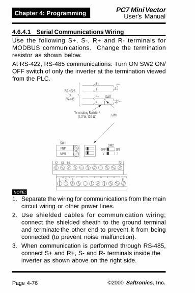
Page 4-76
Chapter 4: Programming PC7 Mini VectorUser’s Manual
©2000 Saftronics , Inc.
4.6.4.1 Serial Communications WiringUse the following S+, S-, R+ and R- terminals forMODBUS communications. Change the terminationresistor as shown below.At RS-422, RS-485 communications: Turn ON SW2 ON/OFF switch of only the inverter at the termination viewedfrom the PLC.
1. Separate the wiring for communications from the maincircuit wiring or other power lines.
2. Use shielded cables for communication wiring;connect the shielded sheath to the ground terminaland terminate the other end to prevent it from beingconnected (to prevent noise malfunction).
3. When communication is performed through RS-485,connect S+ and R+, S- and R- terminals inside theinverter as shown above on the right side.
NOTE:

Page 4-77
Chapter 4: ProgrammingPC7 Mini VectorUser’s Manual
©2000 Saftronics , Inc.
4.6.4.2 Procedure for Communication with PLCThe following shows the procedure for communicationswith PLC.(1) Connect the communication cable between the PLC
and the PC7 with the power supply turned OFF.(2) Turn the power ON.(3) Set the parameters (n151 to n157) required for
communication by using the digital operator.(4) Turn the power OFF once to verify that the digital
operator displays have been completely erased.(5) Turn the power ON again.(6) Communications with the PLC starts.

Page 4-78
Chapter 4: Programming PC7 Mini VectorUser’s Manual
©2000 Saftronics , Inc.
4.6.4.3 Setting Parameters for CommunicationCommunication related parameters must be set forMODBUS communication. Parameters n151 to n157cannot be set during communication. Always set themprior to performing communication.
retemaraP retemaraP retemaraP retemaraP retemaraP emaN emaN emaN emaN emaN noitpircseD noitpircseD noitpircseD noitpircseD noitpircseD yrotcaF yrotcaF yrotcaF yrotcaF yrotcaFgnitteS gnitteS gnitteS gnitteS gnitteS
300n noitcelesdnammocnuR
:0:1:2:3
rotareposlanimrettiucriclortnoc
noitacinummoc)lanoitpo(dracnoitacinummoc
0
400n ecnereferycneuqerFnoitceles
:0:1:2:3:4:5:6:7:8:9
)rotarepolatigid(retemoitnetoplacol)420n(1.ferycneuqerf
)V01ot0egatlov(slanimrettiucriclortnoc)Am02ot4tnerruc(slanimrettiucriclortnoc)Am02ot0tnerruc(slanimrettiucriclortnoc
niarteslup)112000,onretsiger(noitacinummocSUBDOM
)V01ot0egatlov(slanimrettiucricrotarepo)Am02ot4tnerruc(slanimrettiucricrotarepo
)lanoitpo(dracnoitacinummoc
0
151n
noitcetedrevoemiTnoitceles
emitnoissimsnartsrotinoMehtgniviecerehtneewtebCLPehtmorfatadtcerroc
)ces2:revoemiT(
:0:1
:2
:3
:4
)potsnureerf(noitcetedrevoemitdeepshtiwpotsaotgnitsaoc(noitcetedrevoemit
)1emitnoitcuderdeepshtiwpotsaotgnitsaoc(noitcetedrevoemit
)2emitnoitcudergninraw,noitareposuounitnoc(noitcetedrevoemit
)yalpsiddedivorptonnoitcetedrevoemit
0
251nycneuqerfnoitacinummoC
tinurotinomecnerefeRnoitceles
:0:1:2:3
zH1,0zH1.0:0
)ycneuqerftuptuo.xam=00003(%001/00003%1.0
0
351n sserddaevalS *23ot0:egnargnitteS 0
451n noitcelesetarduaB
:0:1:2:3
spb0042spb0084spb0069spb00291
2
551n noitcelesytiraP:0:1:2
ytirapneveytirapddo
ytirapon0
651 emitgnitiawgnidneS sm1:tinugnittessm56otsm01:timilgnitteS sm01
751n lortnocSTR :0:1
lortnocSTR)noitacinummoc1ot1A224-SR(lortnocSTRon 0
*The slave does not respond to the command from the master when set to 0.
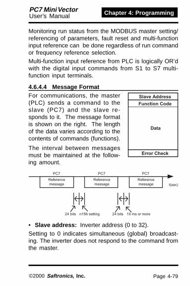
Page 4-79
Chapter 4: ProgrammingPC7 Mini VectorUser’s Manual
©2000 Saftronics , Inc.
Monitoring run status from the MODBUS master setting/referencing of parameters, fault reset and multi-functioninput reference can be done regardless of run commandor frequency reference selection.Multi-function input reference from PLC is logically OR’dwith the digital input commands from S1 to S7 multi-function input terminals.
4.6.4.4 Message FormatFor communications, the master(PLC) sends a command to theslave (PC7) and the slave re-sponds to it. The message formatis shown on the right. The lengthof the data varies according to thecontents of commands (functions).
The interval between messagesmust be maintained at the follow-ing amount.
• Slave address: Inverter address (0 to 32).Setting to 0 indicates simultaneous (global) broadcast-ing. The inverter does not respond to the command fromthe master.
Error Check
Data
Function Code
Slave Address
t(sec)
PC7PC7PC7
Referencemessage
Referencemessage
Referencemessage
10 ms or more24 bitsn156 setting24 bits

Page 4-80
Chapter 4: Programming PC7 Mini VectorUser’s Manual
©2000 Saftronics , Inc.
• Function code: Command codes (See below)
• Data: Composes a series of data by combining hold-ing register numbers (test codes for loop-back numbers)and their data. Data length depends on the contents ofthe commands.
• Error check: CRC-16 (Calculate the value by thefollowing method).
1. The default value at calculation of CRC-16 is normally0. In the MODBUS system, change the default to 1 (all1 to 16-bit).
2. Calculate CRC-16 assuming that the loop address LSBis MSB and the last data MSB is LSB.
3. Also calculate CRC-16 for a response message fromthe slave and refer it to CRC-16 in the responsemessage.
noitcnuF noitcnuF noitcnuF noitcnuF noitcnuFedoC edoC edoC edoC edoC noitcnuF noitcnuF noitcnuF noitcnuF noitcnuF
egasseMecnerefeR egasseMecnerefeR egasseMecnerefeR egasseMecnerefeR egasseMecnerefeR egasseMesnopseR egasseMesnopseR egasseMesnopseR egasseMesnopseR egasseMesnopseR
)etyB(.niM )etyB(.niM )etyB(.niM )etyB(.niM )etyB(.niM )etyB(.xaM )etyB(.xaM )etyB(.xaM )etyB(.xaM )etyB(.xaM )etyB(.niM )etyB(.niM )etyB(.niM )etyB(.niM )etyB(.niM )etyB(.xaM )etyB(.xaM )etyB(.xaM )etyB(.xaM )etyB(.xaM
H10 gnidlohgnidaeRstnetnocrotsiser 8 8 7 73
H80 tsetkcabpooL 8 8 8 8
H01 larevesnietirWsrotsisergnidloh 11 14 8 8

Page 4-81
Chapter 4: ProgrammingPC7 Mini VectorUser’s Manual
©2000 Saftronics , Inc.
4.6.4.5 Data Read Command [03H]This command reads out the contents of the holdingregisters with the continuous numbers for the specifiedquantity. The contents of holding register is divided intothe upper 8 bits and the lower 8 bits. They become thedata items in response message in the order ofnumbers.Example: Reads out status signal, fault contents, datalink status and frequency reference from the PC7 (slave2).
egassemecnerefeR)noitarepolamronta(
sserddAevalS H20
edoCnoitcnuF H30
rebmuNtratSreppU H00rewoL H02
ytitnauQreppU H00rewoL H40
61-CRCreppU H54rewoL H0F
egassemesnopseR)ecneruccotluafta(
sserddAevalS H20
edoCnoitcnuF H38
edoCrorrE H30
61-CRCreppU H1FrewoL H13
egassemesnopseR)noitarepolamronta(
sserddAevalS H20
edoCnoitcnuF H30
*ataDforebmuN H80
gnidlohtsriFrotsiser
reppU H00rewoL H56
gnidlohtxeNrotsiser
reppU H00rewoL H00
gnidlohtxeNrotsiser
reppU H00rewoL H00
gnidlohtxeNrotsiser
reppU H10rewoL H4F
61-CRCreppU HFArewoL H28
forebmunehtsahcumsaeciwT*.egassemecnerefer

Page 4-82
Chapter 4: Programming PC7 Mini VectorUser’s Manual
©2000 Saftronics , Inc.
Command message is returned as a response mes-sage without being changed. This function is used tocheck transmission between the master and the slave.Any arbitrary values can be used for test codes or data.Example: Loop-back test of slave 1 and PC7.
4.6.4.6 Example of Loop-Back Test (08H)
egassemesnopseR)noitarepolamronta(
sserddAevalS H10
edoCnoitcnuF H80
rebmuNtratSreppU H00rewoL H00
ytitnauQreppU H5ArewoL H73
61-CRCreppU HADrewoL HD8
egassemecnerefeR)ecneruccotluafta(
sserddAevalS H10
edoCnoitcnuF h98
edoCrorrE H10
61-CRCreppU h68rewoL H05
egassemesnopseR)noitarepolamronta(
sserddAevalS H10
edoCnoitcnuF H80
rebmuNtratSreppU H00rewoL H00
ytitnauQreppU H5ArewoL H73
61-CRCreppU HADrewoL HD8

Page 4-83
Chapter 4: ProgrammingPC7 Mini VectorUser’s Manual
©2000 Saftronics , Inc.
Specified data can be written into multiple consecutiveregisters. Written data must be arranged in a commandmessage in the order of the holding register numbers:from upper eight bits to lower eight bits.Example: Set forward run at frequency reference 60.0 Hzto slave 1 PC7 from the PLC.
4.6.4.7 Data Write Command [10H]
egassemecnerefeR)noitarepolamronta(
sserddAevalS H10edoCnoitcnuF H01
rebmuNtratSreppU H00rewoL H10
ytitnauQreppU H00rewoL H20
*ataDforebmuN H40
ataDtsriFreppU H00rewoL H10
ataDtxeNreppU H20rewoL H85
61-CRCreppU H36rewoL H93
ehtsaegralsaeciwtsteS*rebmunlautca
egassemesnopseR)noitarepolamronta(
sserddAevalS H10edoCnoitcnuF H01
rebmuNtratSreppU h00rewoL H10
ytitnauQreppU H00rewoL H20
61-CRCreppU H01rewoL H80
egassemecnerefeR)ecneruccotluafta(
sserddAevalS H10edoCnoitcnuF H98
edoCrorrE H10
61-CRCreppU H68rewoL H05

Page 4-84
Chapter 4: Programming PC7 Mini VectorUser’s Manual
©2000 Saftronics , Inc.
• Reference Data (available to read out / write in)
.oNretsigeR .oNretsigeR .oNretsigeR .oNretsigeR .oNretsigeR tib tib tib tib tib noitpircseD noitpircseD noitpircseD noitpircseD noitpircseD
H0000 devreseR
H1000
0 dnammoCnuR nuR:1 potS:0
1 nuResreveR nuResreveR:1 nuRdrawroF:0
2 tluaFlanretxE )OFE(tluaF:1
3 teseRtluaF dnammocteseR:1
4 1ecnerefertupninoitcnuf-itluM )050nybdetcelesnoitcnuF(
5 2ecnerefertupninoitcnuf-itluM )150nybdetcelesnoitcnuF(
6 3ecnerefertupninoitcnuf-itluM )250nybdetcelesnoitcnuF(
7 4ecnerefertupninoitcnuf-itluM )350nybdetcelesnoitcnuF(
8 5ecnerefertupninoitcnuf-itluM )450nybdetcelesnoitcnuF(
9 6ecnerefertupninoitcnuf-itluM )550nybdetcelesnoitcnuF(
A 7ecnerefertupninoitcnuf-itluM )650nybdetcelesnoitcnuF(
F-B )desUtoN(
H2000 )251n:tinu(ecnereferycneuqerF
H3000 )%001/0001(niagf/V %0.002~%0.2:egnargnitteS
H8000-H4000 devreseR
H9000
0 1ecnerefertuptuonoitcnuf-itluM)81=750nnehwevitceffE( )FFOAM=0NOAM:1(
1 2ecnerefertuptuonoitcnuf-itluM)81=850nnehwevitceffE( )FFOAM=0NO1P:1(
2 3ecnerefertuptuonoitcnuf-itluM)81=950nnehwevitceffE( )FFOAM=0NO2P:1(
F-3 )desUtoN(
HF100-HA000 devreseR
Note: Write in “0” for unused bit. Never write in data for the reserved register.
4.6.4.8 Data

Page 4-85
Chapter 4: ProgrammingPC7 Mini VectorUser’s Manual
©2000 Saftronics , Inc.
• Simultaneous (Global) Broadcasting Data(available only for data writes)
Bit signals not defined as the global broadcast signals areused as the local station data signals.
• Monitor Data (Read only).oNretsigeR .oNretsigeR .oNretsigeR .oNretsigeR .oNretsigeR tib tib tib tib tib noitpircseD noitpircseD noitpircseD noitpircseD noitpircseD
H0200
0 dnammoCnuR nuR:1 potS:01 nuResreveR nuresreveR:1 nurdrawroF:02 ydaernoitareporetrevnI ydaeR:1 ydaertoN:03 tluaF tluaF:14 rorregnittesataD rorrE:15 1tuptuonoitcnuf-itluM NOAM:1( )FFOAM:06 2tuptuonoitcnuf-itluM NO1P:1( )FFO:07 3tuptuonoitcnuf-itluM NO2P:1( )FFO:0F-8 )desUtoN(
H1200
0 )CO(tnerrucrevO1 )VO(egatlovrevO2 )2LO(daolrevoretrevnI3 )HO(taehrevoretrevnI4 )desUtoN(5 )desUtoN(6 )LbF(ssolkcabeefDIP7 )OFE,FE(tluaflanretxE )PTS(potsycnegremE8 )xxF(tluaferawdraH9 )1LO(daolrevorotoMA )3LO(noitcetedeuqrotrevOB )desUtoN(C )1VU(ssolrewoPD )2VU(tluafrewoplortnoCE )EC(revoemitsnoitacinummocSUBDOMF )RPO(noitcennocrotarepO
Stat
us S
igna
lFa
ult
Des
crip
tion
.oNretsigeR .oNretsigeR .oNretsigeR .oNretsigeR .oNretsigeR tib tib tib tib tib noitpircseD noitpircseD noitpircseD noitpircseD noitpircseD
H1000
0 dnammoCnuR nuR:1 potS:01 nuResreveR nuResreveR:1 nuRdrawroF:02 )desUtoN(3 )desUtoN(4 tluaFlanretxE )OFE(tluaF:15 teseRtluaF dnammoctesertluaF:1F-6 )desUtoN(
H2000 tinudexif%001/00003.)ffodednuorerasnoitcarfdna,retrevniehtedisnizH10.0otnidetrevnocsiataD(

Page 4-86
Chapter 4: Programming PC7 Mini VectorUser’s Manual
©2000 Saftronics , Inc.
.oNretsigeR .oNretsigeR .oNretsigeR .oNretsigeR .oNretsigeR tib tib tib tib tib noitpircseD noitpircseD noitpircseD noitpircseD noitpircseD
H2200
0 nietirwataD1 )desUtoN(2 )desUtoN(3 tluaftimilrewol/reppU4 tluafycnetsisnoCF-5 )desUtoN(
H3200 )251n:tinU(ecnereferycneuqerFH4200 )251n:tinU(ycneuqerftuptuO
H6200-H5200 )desUtoN(H7200 )A1/01(tnerructuptuOH8200 )V1/1(ecnereferegatlovtuptuO
HA200-H9200 devreseR
HB200
0 1SlanimreT desolC:1 nepO:01 2SlanimreT desolC:1 nepO:02 3SlanimreT desolC:1 nepO:03 4SlanimreT desolC:1 nepO:04 5SlanimreT desolC:1 nepO:06 6SlanimreT desolC:1 nepO:0F-7 )desUtoN(
HC200
0 nuR nuR:11 deeps-oreZ deeps-oreZ:12 deergaycneuqerF deergA:13 )detacidnisimralA(tluafroniM4 1noitcetedycneuqerF )590n(ycneuqerftuptuO:15 2noitcetedycneuqerF )590n(ycneuqerftuptuO:16 ydaernoitareporetrevnI ydaeR:17 noitcetedegatlovrednU noitcetedegatlovrednU:18 kcolbesaB kcolbesabtuptuoretrevnI:19 edomecnereferycneuqerF snoitacinummocnahtrehtO:1 snoitacinummoc:0A edomdnammocnuR snoitacinummocnahtrehtO:1 snoitacinummoc:0B noitcetedeuqrotrevO tluafeuqrotrevoronoitceteD:1C )desUtoN(D tratsertluaFE )revoemitsnoitacinummocSUBDOMgnidulcnI(tluaF tluaF:1F revoemitsnoitacinummocSUBDOM revoemiT:1
Inve
rter
Sta
tus
Sequ
ence
Inpu
t Sta
tus
Data
Lin
k St
atus
<=<=

Page 4-87
Chapter 4: ProgrammingPC7 Mini VectorUser’s Manual
©2000 Saftronics , Inc.
.oNretsigeR .oNretsigeR .oNretsigeR .oNretsigeR .oNretsigeR tib tib tib tib tib noitpircseD noitpircseD noitpircseD noitpircseD noitpircseD
HD200
0 "NO"AM desolC:1 nepO:01 "NO"1P desolC:1 nepO:02 "NO"2P desolC:1 nepO:0F-3 )desUtoN(
H0300-HE200 devreseRH1300 )V1/1(egatlovCDtiucricniaMH2300 rotinomeuqroT
H6300-H3300 )desUtoN(
H7300 htiw:W1/1(rewoptuptuO)ngis
H8300 tuohtiw;%1/01;ycneuqerftuptuo.xamottnelaviuqetupnI/%001(eulavkcabdeefDIP)ngis
H9300 (eulavtupniDIP + /%001 + )ngishtiw;%1/01;ycneuqerftuptuo.xaMHA300 (eulavtupniDIP + /%001 + )ngishtiw;%1/01;ycneuqerftuptuo.xaM
HD300
0 rorreCRC1 "NO"1P2 )desUtoN(3 rorreytiraP4 rorrenurrevO5 rorregnimarF6 revoemiT7 )desUtoN(
HFF00-HE300 devreseR
* Communications error contents are saved until fault reset is input.(Reset is enabled during run.)
Com
mun
icatio
ns E
rror
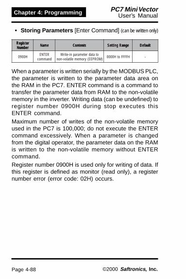
Page 4-88
Chapter 4: Programming PC7 Mini VectorUser’s Manual
©2000 Saftronics , Inc.
• Storing Parameters [Enter Command] (can be written only)
retsigeR retsigeR retsigeR retsigeR retsigeRrebmuN rebmuN rebmuN rebmuN rebmuN emaN emaN emaN emaN emaN stnetnoC stnetnoC stnetnoC stnetnoC stnetnoC egnaRgnitteS egnaRgnitteS egnaRgnitteS egnaRgnitteS egnaRgnitteS tluafeD tluafeD tluafeD tluafeD tluafeD
H0090 RETNEdnammoc
otatadretemarapni-etirW)MORPEE(yromemelitalov-non HFFFFotH0000 -
When a parameter is written serially by the MODBUS PLC,the parameter is written to the parameter data area onthe RAM in the PC7. ENTER command is a command totransfer the parameter data from RAM to the non-volatilememory in the inverter. Writing data (can be undefined) toregister number 0900H during stop executes thisENTER command.Maximum number of writes of the non-volatile memoryused in the PC7 is 100,000; do not execute the ENTERcommand excessively. When a parameter is changedfrom the digital operator, the parameter data on the RAMis written to the non-volatile memory without ENTERcommand.Register number 0900H is used only for writing of data. Ifthis register is defined as monitor (read only), a registernumber error (error code: 02H) occurs.

Page 4-89
Chapter 4: ProgrammingPC7 Mini VectorUser’s Manual
©2000 Saftronics , Inc.
• Error CodesedoCrorrE edoCrorrE edoCrorrE edoCrorrE edoCrorrE stnetnoC stnetnoC stnetnoC stnetnoC stnetnoC
H10rorreedocnoitcnuF
.H01roH80,H30nahtrehtosiCLPmorfedocnoitcnuF·
H20rebmunretsigerreporpmI
.deretsigerneebevahdesseccaebotsrebmunretsigeroN·.tuodaersawni-etirwrofretsigeresu-evisulcxenasitaht"H0090"dnammocRETNE·
H30
ytitnauqreporpmI.61dna1neewtebegnarehtnitonsini-etirwrodaerebotsmetiatadforebmunehT·
ehtgniylpitlumybdeniatboeulavehttonsiegassemanismetiatadforebmunehT·.edomni-etirwehtniowtybytitnauq
H12rorregnittesataD
.ni-etirwretemaraproatadlortnochtiwderruccororretimilrewol/reppuelpmisA·.nettirwsawretemarapanehwderruccororregnittesretemarapA·
H22
rorreedomni-etirW.gninnurgnirudedamsawCLPmorfretemarapani-etirwottpmettA·
.gninnurgnirudedamsawCLPmorfdnammocRETNEnani-etirwottpmettA·.ecnerruccoVUgnirudedamsawCLPmorfretemarapani-etirwottpmettA·
.ecnerruccoVUgnirudedamsawCLPmorfdnammocRETNEnani-etirwottpmettA·sawCLPmorf)noitazilaitini(31,21=100nnahtrehtoretemarapani-etirwottpmettA·
.ecnerrucco"40F"gnirudedam.derotsgnieberewatadelihwedamsawCLPmorfretemarapani-etirwottpmettA·
.edamsawCLPmorftuo-daerrofevisulcxeatadni-etirwottpmettA·.noitarepogniruddegnahcebnactahtsretemaraproftsilsretemarapehtotrefeR*

Page 4-90
Chapter 4: Programming PC7 Mini VectorUser’s Manual
©2000 Saftronics , Inc.
PC7 is provided with a self diagnostic check. It isavailable to test the serial communication I/F circuit. Thisfunction is called “self-test”. During connect the sendingterminal with the receiving terminal in the communica-tions section. It assures that the data received by the PC7is not being changed. It also checks if the data can bereceived normally. Carry out the self-test in the followingprocedure.(1) Turn ON the PC7 mini power supply. Set parameter
n056 to 35 (self-test).(2) Turn OFF the PC7 mini power supply.(3) Make the following wiring with the power supply
turned OFF.(4) Turn the power ON.
(Note: Select NPN side for SW1)
Normal operation: Operator displays frequency referencevalue.Fault operation: Operator displays “CE”, fault signal isturned ON and inverter ready signal is turned OFF.Refer to page 4-71 for n158 to n160
4.6.5 Performing Self-test

Page 4-91
Chapter 4: ProgrammingPC7 Mini VectorUser’s Manual
©2000 Saftronics , Inc.
When the power fluctuation is less than this value, theoutput voltage is held for 3 seconds. Then the searchoperation mode is activated. Set the hold width in % of thepower which is currently held.
• Power Detection Filter Time Parameter (n162)Response to load changes are improved when this valueis reduced. However, at low frequency, unstable rotationmay result.
.oNretemaraP .oNretemaraP .oNretemaraP .oNretemaraP .oNretemaraP emaN emaN emaN emaN emaN tinU tinU tinU tinU tinU egnaRgnitteS egnaRgnitteS egnaRgnitteS egnaRgnitteS egnaRgnitteS gnitteSyrotcaF gnitteSyrotcaF gnitteSyrotcaF gnitteSyrotcaF gnitteSyrotcaF
161n noitarepohcraeStimilegatlov % 001ot0 0
.oNretemaraP .oNretemaraP .oNretemaraP .oNretemaraP .oNretemaraP emaN emaN emaN emaN emaN tinU tinU tinU tinU tinU egnaRgnitteS egnaRgnitteS egnaRgnitteS egnaRgnitteS egnaRgnitteS gnitteSyrotcaF gnitteSyrotcaF gnitteSyrotcaF gnitteSyrotcaF gnitteSyrotcaF
261n retlifnoitcetedrewoPretemarapemit sm4x 522ot0 )sm02(5
4.6.6 Search Operation Power Detection Hold Width(n161)
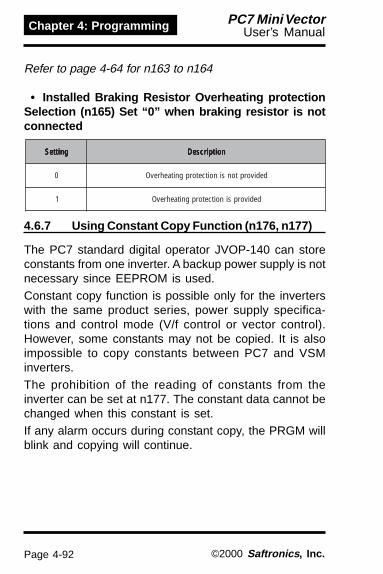
Page 4-92
Chapter 4: Programming PC7 Mini VectorUser’s Manual
©2000 Saftronics , Inc.
Refer to page 4-64 for n163 to n164
• Installed Braking Resistor Overheating protectionSelection (n165) Set “0” when braking resistor is notconnected
gnitteS gnitteS gnitteS gnitteS gnitteS noitpircseD noitpircseD noitpircseD noitpircseD noitpircseD
0 dedivorptonsinoitcetorpgnitaehrevO
1 dedivorpsinoitcetorpgnitaehrevO
4.6.7 Using Constant Copy Function (n176, n177)
The PC7 standard digital operator JVOP-140 can storeconstants from one inverter. A backup power supply is notnecessary since EEPROM is used.Constant copy function is possible only for the inverterswith the same product series, power supply specifica-tions and control mode (V/f control or vector control).However, some constants may not be copied. It is alsoimpossible to copy constants between PC7 and VSMinverters.The prohibition of the reading of constants from theinverter can be set at n177. The constant data cannot bechanged when this constant is set.If any alarm occurs during constant copy, the PRGM willblink and copying will continue.

Page 4-93
Chapter 4: ProgrammingPC7 Mini VectorUser’s Manual
©2000 Saftronics , Inc.
.oNretemaraP .oNretemaraP .oNretemaraP .oNretemaraP .oNretemaraP emaN emaN emaN emaN emaN tinU tinU tinU tinU tinU egnaRgnitteS egnaRgnitteS egnaRgnitteS egnaRgnitteS egnaRgnitteS gnitteSyrotcaF gnitteSyrotcaF gnitteSyrotcaF gnitteSyrotcaF gnitteSyrotcaF
671n ypoctnatsnoCnoitcelesnoitcnuf -
YDAER:ydrDAER:dErYPOC:yPCYFIREV:yFv
yalpsidyticapacretrevnI:Avyalpsid.oNerawtfoS:onS
ydr
Select this function to prevent accidentally overwriting theconstants stored in EEPROM or in the digital operator.Reading is not possible when this constant is set to 0.
The constant data stored in the digital operator are safefrom accidental overwriting.When reading is performed while this constant is set to0, PrE will blink. Press the DSPL or ENTER and return tothe constant number display.
.oNretemaraP .oNretemaraP .oNretemaraP .oNretemaraP .oNretemaraP emaN emaN emaN emaN emaN tinU tinU tinU tinU tinU egnaRgnitteS egnaRgnitteS egnaRgnitteS egnaRgnitteS egnaRgnitteS gnitteSyrotcaF gnitteSyrotcaF gnitteSyrotcaF gnitteSyrotcaF gnitteSyrotcaF
771n daertnatsnoCtibihorpnoitceles 1 detibihorpDAER:0
dewollaDAER:1 0
Depending on the setting of n176 for constant copyfunction selection, the following functions are available.(1) Read all the constants from the inverter (READ) and
store them in EEPROM in the digital operator.(2) Copies the constants stored in the digital operator to
the inverter (COPY).(3) Verify the constants in the digital operator and the
constants in the inverter are the same (VERIFY).(4) Displays the maximum applicable motor capacity and
the voltage class of the inverter that has theconstants stored in the digital operator.
(5) Displays the software number of the inverter that hasthe constants stored in the digital operator.
4.6.7.1 Constant Copy Function Selection (n176)
4.6.7.2 Prohibiting Constant Read Selection (n177)

Page 4-94
Chapter 4: Programming PC7 Mini VectorUser’s Manual
©2000 Saftronics , Inc.
The function of the parameter is to upload parameters.This command will instruct the digital operator to read allof the inverter parameters. These parameters can thanbe copied to other inverters by simply executing theparameter “write” command. This “copy” unit function canbe used to quickly program multiple inverters.Example: Store the constants from the inverter in theEEPROM inside the digital operator.
noitanalpxE noitanalpxE noitanalpxE noitanalpxE noitanalpxE yalpsiDrotarepO
····· ehtelbanEehtfognittes
100nstnatsnoc971not
····· ]MGRP[thgilotLPSDsserP 100 tnatsnoctnereffidaebnaC().oN
····· ehtyalpsidotRETNEsserPeulavtes
1 testnereffidaebnaC()tiL()eulav
····· yb4oteulavtesehtegnahC.yekrognisserp
4 )sknilB(
····· .RETNEsserP 4 )dnocesenoroftiL(
····· tnatsnocteSdetibihorpdaer
noitcelesDAERot)771n(
1*.delbane
····· ot.ONtnatsnocehtegnahCrognisserpyb771n
.yek
N 771
····· ehtyalpsidotRETNEsserP.eulavtes
0 )tiL(
····· yb1oteulavtesehtegnahC.yekroehtgnisserp
1 )sknilB(
····· .RETNEsserP1 )dnocesenoroftiL(
N 771 )deyalpsidtnatsnocehT(
····· etucexEretemarap
)DAER(daolpunoitcnuFyb
.671n
····· yb.oNtnatsnocehtegnahC.yekrognisserp
N 671
····· ehtyalpsidotRETNEsserP.eulavtes
RED )tiL(
····· ybdEroteulavtesehtegnahC.yekrognisserp
RED )tiL(
····· RETNEsserP
RED )DAERgnitucexeelihwsknilB(
ENDehtretfadeyalpsidsidnE(
siDAERfonoitucexe)detelpmoc
····· RETNEroLPSDsserP N 671 )deyalpsidsitnatsnocehT(
····· tnatsnocteSdetibihorpdaer
noitcelesDAERot)771n(
2*.delbasid
····· rebmuntnatsnocehtegnahCrognisserpyb771not
.yek
N 771
1 )tiL(
····· ehtyalpsidotRETNEsserP.eulavtes 0 sknilB(
····· yb0oteulavtesehtegnahC.yekrognisserp 0 )etunimenoroftiL(
····· RETNEsserP N 771 sirebmuntnatsnocehT()deyalpsid
.yrassecentonsignittessiht,)1=771n(delbanesiDAERnehW1*.detcelessinoitibihorpDAERsselnuyrassecentonsignittesehT2*
<
<<
<<
<
<<
<
<
<
<
<
<
4.6.7.3 Read (Upload) Function

Page 4-95
Chapter 4: ProgrammingPC7 Mini VectorUser’s Manual
©2000 Saftronics , Inc.
Writes the constant stored inside the digital operator tothe PC7. This download is possible only when inverterswith the same product series, power supply specifica-tions and control mode (V/f control or vector control).Therefore, writing from 200 V class to 400 V class (or viceversa), from V/f control mode to vector control mode (orvice versa), and from the PC7 to any other inverter is notpossible.Constant Copy Function (n176), Constant ReadProhibited (n177), Fault History (n178), Inverter SoftwareNumber (n179) and hold output frequency are notwritten.The following constants are not written if the invertercapacity is different.
.oNtnatsnoC .oNtnatsnoC .oNtnatsnoC .oNtnatsnoC .oNtnatsnoC emaN emaN emaN emaN emaN .oNtnatsnoC .oNtnatsnoC .oNtnatsnoC .oNtnatsnoC .oNtnatsnoC emaN emaN emaN emaN emaN
710not110n gnittesf/V 801n ecnatcudniegakaelrotoM
630n tnerrucdetarrotoM 901n retimilegatlovnoitasnepmoceuqroT
080n ycneuqerfreirraC 011n tnerrucdaol-onrotoM
501n ssolnorinoitasnepmoceuqroT 041n 2Ktneiciffeocgnivas-ygrenE
601n pilsdetarrotoM 851n edocrotoM
701n esahpenorofecnatsiserrotoM
4.6.7.4 Copy (Download) Function

Page 4-96
Chapter 4: Programming PC7 Mini VectorUser’s Manual
©2000 Saftronics , Inc.
Example:Write the constants from EEPROM inside the digitaloperator to the inverter.
noitanalpxE noitanalpxE noitanalpxE noitanalpxE noitanalpxE yalpsiDrotarepO yalpsiDrotarepO yalpsiDrotarepO yalpsiDrotarepO yalpsiDrotarepO
····· gnittesehtelbanEstnatsnocehtrof
971not100n
····· ]MGRP[thgilotLPSDsserP N 100 ).oNtnatsnoctnereffidaebnaC(
····· ehtyalpsidotRETNEsserP.eulavtes
1 testnereffidaebnaC()tiL()eulav
····· yb4oteulavtesehtegnahC.yekrognisserp
4 )sknilB(
····· .RETNEsserP 4
N 100
)dnocesenoroftiL(
)deyalpsidsi.oNtnatsnocehT(
····· etucexE)YPOC(daolnwod
ypoctnatsnocyb)671n(noitcnuf
····· ot.oNtnatsnocehtegnahCgnisserpyb671n
.yekro
N 671
····· ehtyalpsidotRETNEsserP.eulavtes
RDY )tiL(
····· yPCoteulavtesehtegnahC.yekrognisserpyb
PC Y )tiL(
····· RETNEsserP PC Y )YPCgnitucexeelihwsknilB(
····· RETNEroLPSDsserP END
N 671
ehtnehwdeyalpsidsidnE()detelpmocsiYPCfonoitucexe
)deyalpsidsi.oNtnatsnocehT(
A setting range check and matching check for thetransferred constants are executed after the constantsare copied from the digital operator to the inverter. If anyconstant error is found, the written constants arediscarded and the previous are retained.When a setting range error is found, the constantnumber where an error occurs is indicated by blinking.When a matching error is found, oP ( : a number)is indicated by blinking.
<
<
<
<
<<

Page 4-97
Chapter 4: ProgrammingPC7 Mini VectorUser’s Manual
©2000 Saftronics , Inc.
This function compares the constants stored in thedigital operator with the constants in the inverter. As wellas download, VERIFY is possible only for the inverterswith same product series, power supply specificationsand control mode (V/f control or vector control). When theconstants stored in the digital operator match those inthe inverter, vFyvFyvFyvFyvFy is displayed by blinking, the End is dis-played. Example: Compare the constants stored inEEPROM inside the digital operator with the constants inthe inverter.
noitanalpxE noitanalpxE noitanalpxE noitanalpxE noitanalpxE yalpsiDrotarepO yalpsiDrotarepO yalpsiDrotarepO yalpsiDrotarepO yalpsiDrotarepO
····· rofgnittesehtelbanEot100nstnatsnoceht
971n
····· ]MGRP[thgilotLPSDsserP N 100 ).oNtnatsnoctnereffidaebnaC(
····· ehtyalpsidotRETNEsserP.eulavtes
1 )eulavtestnereffidaebnaC()tiL(
····· yb4oteulavtesehtegnahC.yekrognisserp
4 )sknilB(
····· .RETNEsserP 4
N 100
)dnocesenoroftiL(
)deyalpsidsi.oNtnatsnocehT(
····· ybYFIREVetucexEnoitcnufypoctnatsnoc
)671n(noitceles
····· ot.oNtnatsnocehtegnahCrognisserpyb671n
.yek
N 671
····· ehtyalpsidotRETNEsserP.eulavtes
RDY )tiL(
····· yFvoteulavtesehtegnahC.yekrognisserp
VFY )tiL(
····· RETNEsserP VFY )YFIREVgnitucexeelihwsknilB(····· dehctamnuehtyalpsiD
.oNtnatsnocN 100 si100nnehW()sknilB(
)dehctamnu····· tnatsnocehtyalpsiD
retrevniehtnieulav 0.06 )sknilB(
····· RETNEsserP 0.05 )sknilB(
····· tnatsnocehtyalpsiDlatigidehtnieulav
.rotarepo····· RETNEsserP
····· noitucexeehteunitnoC.YFIREVfo
····· .yeksserP VFY )YFIREVgnitucexeelihwsknilB(
····· RETNEroLPSDsserP END ehtnehwdeyalpsidsidnE()detelpmocsiYFIREVfonoitucexe
N 671 )deyalpsidsi.oNtnatsnocehT(
While an unmatched constant number is displayed or a constantvalue is displayed pressing STOP/RESET interrups the executionof VERIFY and End is displayed. Pressing DSPL or ENTER returnsto the constant number.
<
<
<<
<
<
<
4.6.7.5 Verify Function

Page 4-98
Chapter 4: Programming PC7 Mini VectorUser’s Manual
©2000 Saftronics , Inc.
The voltage class and maximum applicable motorcapacity (whose constants stored in the digital operatorare read out) are displayed.Example: Display the voltage class and maximumapplicable motor capacity for the inverter whose constantsstored in EEPROM inside the digital operator.
noitanalpxE noitanalpxE noitanalpxE noitanalpxE noitanalpxE yalpsiDrotarepO yalpsiDrotarepO yalpsiDrotarepO yalpsiDrotarepO yalpsiDrotarepO
····· gnittesehtelbanEstnatsnocehtrof
971not100n
····· ]MGRP[thgilotLPSDsserP N 100 ).oNtnatsnoctnereffidaebnaC(
····· tesehtyalpsidotRETNEsserP.eulav
1 testnereffidaebnaC()tiL()eulav
····· yb4oteulavtesehtegnahC.yekrognisserp
4 )sknilB(
····· .RETNEsserP 4
N 100
)dnocesenoroftiL(
)deyalpsidsi.oNtnatsnocehT(
····· retrevnIetucexEyalpsiDyticapaCtnatsnocyb)Av(
noitcnufypoc)671n(noitceles
····· 671not.oNtnatsnocehtegnahC.yekrognisserpyb
N 671
····· tesehtyalpsidotRETNEsserP.eulav
RDY )tiL(
····· ybAvoteulavtesehtegnahC.yekrognisserp
VA )tiL(
····· RETNEsserP 7.02 *)7P02roF()tiL(
····· .RETNEroLPSDsserP N 671 )deyalpsidsi.oNtnatsnocehT(
The following shows the explanation of Inverter CapacityDisplay.
ssalCegatloV2 V002esahP-eerhTb V002esahP-elgniS4 V004esahP-eerhT
yticapaCrotoMelbacilppAxaMssalCV002 ssalCV004
1.0 Wk1.0 -2.0 Wk52.0 Wk73.04.0 Wk55.0 Wk55.07.0 Wk1.1 Wk1.15.1 Wk5.1 Wk5.12.2 Wk2.2 Wk2.20.3 - Wk0.30.4 Wk0.4 Wk0.4
2 0. 7
<
<
<
<<
<
4.6.7.6 Inverter Capacity Display

Page 4-99
Chapter 4: ProgrammingPC7 Mini VectorUser’s Manual
©2000 Saftronics , Inc.
The software version number (of the inverter whoseconstants stored in the digital operator are read out) isdisplayed.Example: Display the software number of the inverterwhose constants stored EEPROM inside the digitaloperator.
noitanalpxE noitanalpxE noitanalpxE noitanalpxE noitanalpxE yalpsiDrotarepO yalpsiDrotarepO yalpsiDrotarepO yalpsiDrotarepO yalpsiDrotarepO
····· gnittesehtelbanEstnatsnocehtrof
971not100n
····· ]MGRP[thgilotLPSDsserP N 100 ).oNtnatsnoctnereffidaebnaC(
····· ehtyalpsidotRETNEsserP.eulavtes
1 )eulavtestnereffidaebnaC()tiL(
····· yb4oteulavtesehtegnahC.yekrognisserp
4 )sknilB(
····· .RETNEsserP 4
N 100
)dnocesenoroftiL(
)deyalpsidsi.oNtnatsnocehT(
····· erawtfoSetucexE*)onS(yalpsiD.oN
ypoctnatsnocybnoitcelesnoitcnuf
.)671n(
····· ot.oNtnatsnocehtegnahCrognisserpyb671n
.yek
N 671
····· ehtyalpsidotRETNEsserP.eulavtes
RDY )tiL(
····· AvoteulavtesehtegnahCrognisserpyb
.yek
SNO )tiL(
····· RETNEsserP 3100 )310010PSV:noisreverawtfos()tiL(
····· .RETNEroLPSDsserP N 671 )deyalpsidsi.oNtnatsnocehT(
*Displays last 4 digits of the software version.
<
<<
<
<
<
4.6.7.7 Software Number Display

Page 4-100
Chapter 4: Programming PC7 Mini VectorUser’s Manual
©2000 Saftronics , Inc.
Display ListrotarepO rotarepO rotarepO rotarepO rotarepO
yalpsiD yalpsiD yalpsiD yalpsiD yalpsiD noitpircseD noitpircseD noitpircseD noitpircseD noitpircseD noitcAevitcerroC noitcAevitcerroC noitcAevitcerroC noitcAevitcerroC noitcAevitcerroC
RDY noitcnufypoctnatsnocrofgnitteS:tiLdelbanenoitceles -
REDdetcelesDAER:tiL
noitucexerednuDAER:dehsalF -
PC Y detceles)YPOC(gnitirW:tiL -
VFYdetcelesYFIREV:tiL
noitucexerednuYFIREV:dehsalF -
VA detcelesyalpsidyticapacretrevnI:tiL -
SNO detcelesyalpsid.oNerawtfoS:tiL -
ENDYFIREVro)gnitirw(YPOC,DAER:tiL
detelpmoc -
PREelihwDAERetucexeottpmettA:sknilB
si)771n(noitceleSdetibihorPdaeRtnatsnoC.0ottes
tesneht,DAERetucexeotytissecenehtmrifnoCot1ot)771n(noitceleSdetibihorPdaeRtnatsnoc
.DAERetucexe
RDE
daerebtondluoctnatsnocehT:sknilBniama,rO.noitarepoDAERebylreporp
DAERgniruddetcetedsiegatlovwoltiucric.noitarepo
ylppusrewoptiucricniamehttahtmrifnoC.DAERetucexe-erneht,tcerrocsiegatlov
ESC ehtnisruccororremuskcehcA:sknilB.rotarepolatigidehtniderotsatadtnatsnoc
rotarepolatigidehtniderotsstnatsnocehT.esuebtonnac
ehtnistnatsnocehterotsotDAERetucexe-eR.rotarepolatigid
D SP morfdetpmettaneebsahdaolnwodA:sknilB.ledomtnereffidaotretrevniledomeno .seirestcudorpemasehterayehtfikcehC
NDR latigidehtniderotsatadtnatsnocoN:sknilB.rotarepo .DAERetucexE
EPCro)YPOC(gnitirwetucexeottpmettA:sknilBrosessalcegatlovtnereffidneewtebYFIREV
.sedomlortnoctnereffid.edomlortnocdnassalcegatlovhcaekcehC
EYC detcetedsiegatlovwoltiucricniamA:sknilB.noitarepo)YPOC(gnitirwgnirud
ylppusrewoptiucricniamehttahtmrifnoC.)YPOC(gnitirwetucexe-ereht,tcerrocsiegatlov
40F tnatsnocehtnisruccororremuskcehcA:tiL.retrevniehtniderotsetad
,niagasruccororrenafI.stnatsnocehtezilaitinItnatsnocfoeruliafaoteudretrevniehtecalper
.retrevniehtni)MORPEE(tnemeleyromem
U ER neewtebYFIREVetucexeottpmettA:sknilB.seiticapacretrevnitnereffid
fonoitucexeehteunitnocotRETNEsserPfonoitucexeehttpurretniotPOTSsserP.YFIREV
.YFIREV
I EF sruccororrenoitacinummocA:sknilB.rotarepolatigidehtdnaretrevniehtneewteb
dnaretrevniehtneewtebnoitcennocehtkcehC.rotarepolatigideht
DAERgnirudsruccororrenoitacinummocafIoteruseb,noitarepo)YPOC(gnitirwronoitarepo
.YPOCroDAERetucexe-er
sirotarepolatigidehtnotupniyek,gniknilbybdeyalpsidsiyFvro,yPC,dErelihW:etoNRETNEroLPSDgnisserp,gniknilbybdeyalpsidtonerayFvdnayPC,dErelihW.delbasid
.rebmuntnatsnocehtsyalpsider

Page 5-1
Chapter 5: PM &Troubleshooting
PC7 Mini VectorUser’s Manual
©2000 Saftronics , Inc.
Chapter 5: PM&Troubleshooting
What this chapter tells you:1) Periodic inspection.2) Parts replacement schedule.3) Troubleshooting poor operation.4) Fault diagnostics.

Page 5-2
Chapter 5: PM &Troubleshooting
PC7 Mini VectorUser’s Manual
©2000 Saftronics , Inc.
!Never touch any high voltage terminals in the inverter.Replace all protective covers before powering up theinverter. Only authorized personnel should bepermitted to perform service on this unit.
The PC7 will provide a long, useful operational life whenyou observe all of the precautions in this manual. It is,however, a good idea to perform regular, periodicinspections to make sure there are no unexpectedproblems. These checks are very simple and will notrequire much time. Table 5.1 (page 5-3) summarizes therecommended checks.
Table 5.2 (page 5-3) gives a recommended partsreplacement schedule. While this is not absolutelyrequired, it can further prolong the useful life of the PC7.
The PC7 gives advanced diagnostic displays to assist inthe troubleshooting of operational problems. Someproblems, however, may not result in a unit fault trip.Refer to Table 5.3 (page 5-4) for typical corrective actions.
5.0 PERIODIC INSPECTION
5.1 PARTS REPLACEMENT SCHEDULE
5.2 OPERATIONAL FAULTS

Page 5-3
Chapter 5: PM &Troubleshooting
PC7 Mini VectorUser’s Manual
©2000 Saftronics , Inc.
Table 5.1 Periodic Inspection
tnenopmoC tnenopmoC tnenopmoC tnenopmoC tnenopmoC kcehC kcehC kcehC kcehC kcehC noitcAevitcerroC noitcAevitcerroC noitcAevitcerroC noitcAevitcerroC noitcAevitcerroC
,lanimretlanretxE,srotcennoc
swercsgnitnuom
slanimretesooLsnoitcennocro )nethgitrevotonod(eruceS
knistaeH ,tsudfopu-dliuBliorotrid riadesserpmocyrd,naelchtiwwolB
tiucriCdetnirPdraoB
fonoitalumuccArotridrotsud
noitarolocsid
.riadesserpmocyrd,naelchtiwwolBecalper,stsisrepmelborpfI
tnenopmocstnenopmoCrewoP
roticapaCsuB ,noitarolocsiDegrahcsid,rodo retrevniehtroroticapacehtecalpeR
nafgnilooC esionlamronbAnoitarbivro nafgniloocehtecalpeR
Table 5.2 Parts Replacement Schedule
tnenopmoC tnenopmoC tnenopmoC tnenopmoC tnenopmoC etamixorppA etamixorppA etamixorppA etamixorppA etamixorppAlavretnI lavretnI lavretnI lavretnI lavretnI skrameR skrameR skrameR skrameR skrameR
)s(roticapaCsuB sraey5 ecalperdnatcepsnI
sesuF sraey01 ecalpeR
nafgnilooC sraey3ot2 ecalpeR
roticapacgnihtoomS sraey5ecalpeR
otdedeennoitcepsnI()noitidnocenimreted
syalerrekaerB - otdedeennoitcepsnI()noitidnocenimreted
sBCPnosroticapacmunimulA sraey5ecalpeR
otdedeennoitcepsnI()noitidnocenimreted

Page 5-4
Chapter 5: PM &Troubleshooting
PC7 Mini VectorUser’s Manual
©2000 Saftronics , Inc.
Table 5.3 Operational Problems
devresbO devresbO devresbO devresbO devresbOmelborP melborP melborP melborP melborP kcehC kcehC kcehC kcehC kcehC noitcAevitcerroC noitcAevitcerroC noitcAevitcerroC noitcAevitcerroC noitcAevitcerroC
dapyekoNnoitanimulli
rewopgnimocnIylppus
tierusekamdnaegatlovtupnierusaeM.ecnarelottinunihtiwsi
egatloVsuBCD .tneserpsiegatlovsubCDyfireV)noDELegrahC()CDV056-CDV023(
gninrutsirotoMnoitceridgnorw
gniriw3T,2T,1T retfasdaelrotomowtynaesreveR.FFOsiyalpsiddnadevomersirewop
gniriWlortnoCkcehC.kosigniriwlortnocerusekaM
tahterusebottinufognimmargorp.tcerrocsignimmargorperiw-3/eriw-2
tonseoddapyeKretemarapwolla
segnahcsseccAkcehC .edommargorpniebtsuM.1
.sseccarof100nretemarapteS.2
tonseodrotoMetarelecca
DELnuR dilavagnittegsievirdehterusekaMdnammocnur
sutatSER/OL yekETOMER/LACOLsserPecnerefeR tneserpecnereferdilaV
egatloVtuptuO retemtlovepytreifitcerhtiwkcehC kooL..egatlovCAdecnalabrof
edoCtluaF ,selbatyalpsidtluafotrefeR31-5urht7-5segap
daoL .dedaolrevotonsirotomerusekaM
sitnerrucrotoMhgih
esahP-elgniS yfirevotretemmanopmalcesU.tnerructuptuoesahp-eerht,decnalab
rotoMsnoitcennoc .egatlovtcerrocrofdetcennocrotomsI
zH/V ehtsehctamnrettapzH/VehterusekaM.etalpemanrotom
daoL .daolevissecxE

Page 5-5
Chapter 5: PM &Troubleshooting
PC7 Mini VectorUser’s Manual
©2000 Saftronics , Inc.
Replacement of Cooling Fan· Inverter of W-Dimension (width) 2.68 inches,
5.51 inches, 6.64 inches
1. Removal(1) Press the right and left clicks of the fan cover and pull
them to remove the fan cover from the inverter unit.(2) Pull the wiring from the fan cover rear face and remove the
protective tube and connector.(3) Open the left and righ sides of the fan cover to remove the
cooling fan from cover.
2. Mounting(1) Mount the cooling fan on the fan cover. The arrow mark to
indicate the wind direction of the cooling fan must be in theopposite side to the cover.
(2) Connect the connector and mount the protective tube firmly.Mount the connector joint section on the fan cover rear face.
(3) Mount the fan cover on the inverter. Be sure to mount theright and left clicks of the fan cover on the heatsink.
· Inverter of W-Dimension (width) 4.25 inches1. Removal
(1) Remove the front cover and terminal cover, and remove thecooling fan connector (CN4)
(2) Press the right and left clicks of the fan cover and pull thefan cover to remove it from the inverter.
(3) Open the right and left sides of the fan cover to remove thecover from the cooling fan.
2. Mounting(1) Mount the cooling fan on the fan cover. The arrow mark to
indicate the wind direction must be opposite the cover.(2) Mount the fan cover on the inverter. Be sure to mount the
right and left clicks of the fan cover on the heatsink. Lead inthe wiring from the cable lead-in hole at the bottom of theplastic case to the inside of the inverter.
(3) Connect the wiring to the cooling fan connector (CN4) andmount the front cover and the terminal cover.

Page 5-6
Chapter 5: PM &Troubleshooting
PC7 Mini VectorUser’s Manual
©2000 Saftronics , Inc.
This section describes the alarm and fault displays,explanations for fault conditions and corrective actions tobe taken if the PC7 malfunctions.
< Corrective actions for models with blank cover >
1. Input fault reset or cycle the power supply OFF and ON.
2. When a fault cannot be corrected:a. Turn the power supply OFF and check the wiring
control logic.b. Turn the power supply OFF and replace the blank
cover with the digital operator to display faults.
5.3 ALARM AND FAULT CODES

Page 5-7
Chapter 5: PM &Troubleshooting
PC7 Mini VectorUser’s Manual
©2000 Saftronics , Inc.
< Corrective actions of models with digital cover >
: ON :BLINKING : OFF
Alarm Display and Contents
yalpsiDmralA yalpsiDmralA yalpsiDmralA yalpsiDmralA yalpsiDmralAretrevnI retrevnI retrevnI retrevnI retrevnI
sutatS sutatS sutatS sutatS sutatS noitanalpxE noitanalpxE noitanalpxE noitanalpxE noitanalpxE dnasesuaC dnasesuaC dnasesuaC dnasesuaC dnasesuaCsnoitcAevitcerroC snoitcAevitcerroC snoitcAevitcerroC snoitcAevitcerroC snoitcAevitcerroClatigiD latigiD latigiD latigiD latigiD
rotarepO rotarepO rotarepO rotarepO rotarepO)neerG(nuR )neerG(nuR )neerG(nuR )neerG(nuR )neerG(nuR)deR(mralA )deR(mralA )deR(mralA )deR(mralA )deR(mralA
uUgniknilB
GNINRAW
tluaFodstcatnocegnahcton
.etats
)egatlovwoltiucricniaM(VUspordegatlovCDtiucricniaM
noitcetedegatlov-wolehtwolebsituptuoretrevniehtelihwlevel
FFO
:gniwollofehtkcehC
•
•
•
ylppusrewoPegatlov
tiucricniaMylppusrewop
signiriwdetcennoc
swercslanimreTylerucesera
denethgit
:V002 suBCDtaspotS.xorppawolebegatlov-elgnisrofV061(V002
)esahp
:V004 suBCDtaspotS.xorppawolebegatlov
V004
vogniknilB
)egatlovrevotiucricniaM(VOehtsdeecxeegatlovsuBCD
elihwlevelnoitcetedegatlovrevo.FFOsituptuoretrevniehtssalcV032:levelnoitceteDssalcV064roV014.xorppa
)CDV028.xorppa
rewopehtkcehCegatlovylppus
lecedehtesaercnIemit
HogniknilB
ekatnI)taehrevonifgnilooC(HOehtelihwsesirerutarepmetria
.FFOsituptuoretrevni
riaekatniehtkcehC.erutarepmet
3HogniknilB
-erpgnitaehrevoretrevnI(3HOtupnisilangis*)mrala
fotupniehtesaeleRgnitaehrevoretrevni
.langismrala-erp
LACgniknilB
snoitacinummocSUBDOM(LACtonsahatadtcerroC)gnitiaw
CLPehtmorfdeviecerneeb300nstnatsnocehtnehw
)noitcelesdnammocnoitarepo(ycneuqerf(400nro2si
dna,6si)noitcelesecnerefer.NOdenrutsirewop
kcehCnoitacinummoc
dnasecivednoissimsnart
.slangis
* .sretrevni)Wk5.7/5.5(pH01/5.7.ssalcV004/002otseilppaylnoyalpsiD

Page 5-8
Chapter 5: PM &Troubleshooting
PC7 Mini VectorUser’s Manual
©2000 Saftronics , Inc.
yalpsiDmralA yalpsiDmralA yalpsiDmralA yalpsiDmralA yalpsiDmralAretrevnI retrevnI retrevnI retrevnI retrevnI
sutatS sutatS sutatS sutatS sutatS noitanalpxE noitanalpxE noitanalpxE noitanalpxE noitanalpxE evitcerroCdnasesuaC evitcerroCdnasesuaC evitcerroCdnasesuaC evitcerroCdnasesuaC evitcerroCdnasesuaCsnoitcA snoitcA snoitcA snoitcA snoitcAlatigiD latigiD latigiD latigiD latigiD
rotarepO rotarepO rotarepO rotarepO rotarepO)neerG(nuR )neerG(nuR )neerG(nuR )neerG(nuR )neerG(nuR)deR(mralA )deR(mralA )deR(mralA )deR(mralA )deR(mralA
OP 0
gniknilB
UU
GNINRAW GNINRAW GNINRAW GNINRAW GNINRAW
tluaFodstcatnocegnahcton
.etats
PO 0 rorregnittestnatsnoC(signittestnatsnocehtnehw
ehthguorhtdemrofrep.snoitacinummocSUBDOM
gnittesehtkcehC.seulav
:1PO
:2PO
:3PO
:4PO
:5PO
eraseulaveromroowTnoitcnuf-itlumroftes
.noitcelestupniot050nstnatsnoc(
)650f/VgnomapihsnoitaleR
tonsistnatsnocstnatsnoc(.tcerroc,410n,310n,110n
)610nfoeulavgnitteS
lamrehtcinortceletnerrucdradnatsfo%051sdeecxe
.tnerrucdetarretrevni)630ntnatsnoc(
fotimilrewol/reppUsiecnereferycneuqerf
stnatsnoc(.desrever)430n,330n
ot380nstnatsnoc()580n
oL 3gniknilB
)noitcetedeuqrotrevO(3LOehtdedeecxetnerrucrotoM
.890ntnatsnocnieulavteserp
dna,daolehtecudeRleced/leccaehtdnapxe
.emit
ES rgniknilB
retrevnI)rorreecneuqeS(REStcelesETOMER/LACOLseviecer
/snoitacinummocrodnammoclanimrettiucriclortnoc
ehtmorfslangisgnignahcelihwlanimretnoitcnuf-itlum
.gnittuptuosiretrevnieht
lanretxeehtkcehC.)ecneuqes(tiucric

Page 5-9
Chapter 5: PM &Troubleshooting
PC7 Mini VectorUser’s Manual
©2000 Saftronics , Inc.
yalpsiDmralA yalpsiDmralA yalpsiDmralA yalpsiDmralA yalpsiDmralAretrevnI retrevnI retrevnI retrevnI retrevnI
sutatS sutatS sutatS sutatS sutatS noitanalpxE noitanalpxE noitanalpxE noitanalpxE noitanalpxE dnasesuaC dnasesuaC dnasesuaC dnasesuaC dnasesuaCsnoitcAevitcerroC snoitcAevitcerroC snoitcAevitcerroC snoitcAevitcerroC snoitcAevitcerroClatigiD latigiD latigiD latigiD latigiD
rotarepO rotarepO rotarepO rotarepO rotarepO)neerG(nuR )neerG(nuR )neerG(nuR )neerG(nuR )neerG(nuR)deR(mralA )deR(mralA )deR(mralA )deR(mralA )deR(mralA
bbgniknilB
GNINRAW GNINRAW GNINRAW GNINRAW GNINRAW
tluaFodstcatnocegnahcton
etats .
)kcolbesablanretxE(BB-itlumtadnammockcolbesaBeht,evitcasilanimretnoitcnuf
FFOtuhssituptuoretrevniyraropmeT.)gnitsaocrotom(
tupninehwderaelcsinoitidnoc.devomersidnammoc
lanretxeehtkcehC)ecneuqes(tiucric
FEgniknilB
nurVER/DWFsuoenatlumiS(FEdnaDWFnehW)sdnammoc
erasdnammocnurVERrevoroftupniylsuoenatlumis
spotsretrevnieht,sm005.500ntnatsnocotgnidrocca
lanretxeehtkcehC)ecneuqes(tiucric
PTSgniknilB
)potsnoitcnufrotarepO(PTS
gniruddesserpsitiucriclortnocehtybgninnur
.dnammocVER/DWFslanimretotgnidroccaspotsretrevniehT
.500ntnatsnoc
retrevnI)potsycnegremE(PTSmralapotsycnegremeseviecer
gnidroccaspotsretrevnI.langis.500ntnatsnocot
VER/DWFnepOlortnocfodnammoc
slanimrettiucric
lanretxeehtkcehC)ecneuqes(tiucric
FAngniknilB
gnilooC)tluafnafgnilooC(NAF.dekcolsinaf
:gniwollofehtkcehCnafgnilooC•
signiriwnafgnilooC•detcennocton
ECgniknilB
)SUBOMEM(ECtluafsnoitacinummoc
ehtkcehCnoitacinummoc
rosecivednoitacinummoc
slangis
FbLgniknilB
ssolkcabdeefDIP(LBF)noitceted
wolebspordeulavkcabdeefDIPDIPnehW.levelnoitcetedehteht,detcetedsissolkcabdeefotgnidroccasetareporetrevni
.gnittes631neht
lacinahcemehtkcehCtcerrocdnametsys
esaercniro,esuaceht731nfoeulaveht
b SUgniknilB
snoitacinummocdracnoitpO.tluaf
sahtluafnoitacinummoCnurtahtedomaniderrucco
ycneuqerfdnadnammocehtmorfteseraecnerefer
.dracnoitponoitacinummoc
ehtkcehCnoitacinummoc
rosecivednoitacinummoc
.slangis
or STOPRESET

Page 5-10
Chapter 5: PM &Troubleshooting
PC7 Mini VectorUser’s Manual
©2000 Saftronics , Inc.
yalpsiDtluaF yalpsiDtluaF yalpsiDtluaF yalpsiDtluaF yalpsiDtluaFretrevnI retrevnI retrevnI retrevnI retrevnI
sutatS sutatS sutatS sutatS sutatS noitanalpxE noitanalpxE noitanalpxE noitanalpxE noitanalpxE snoitcAevitcerroCdnasesuaC snoitcAevitcerroCdnasesuaC snoitcAevitcerroCdnasesuaC snoitcAevitcerroCdnasesuaC snoitcAevitcerroCdnasesuaClatigiD latigiD latigiD latigiD latigiDrotarepO rotarepO rotarepO rotarepO rotarepO
)neerG(nuR )neerG(nuR )neerG(nuR )neerG(nuR )neerG(nuR)deR(mralA )deR(mralA )deR(mralA )deR(mralA )deR(mralA
oC
evitcetorPnoitarepO
situptuOFFOtuhsrotomdnaaotstsaoc
.pots
tuptuoretrevnI)tnerrucrevO(COsdeecxeyliratnemomtnerruc
.tnerrucdetarfo%052.xorppa
•
••
••
•
•
tagnidnuorgrotiucrictrohSedistuptuoretrevni
DGdaolevissecxE 2
diparylemertxE leced/leccaot910nstnatsnoc(emit
)220ndesurotomlaicepS
gnirudrotomgnitratSgnitsaoc
yticapacaforotoM retaergsahgnitarretrevniehtnaht
detratsneebrotcatnoccitengaM
retrevniehttadesolc/nepoedistuptuo
CS
*)tiucric-trohSdaoLsawdaolrotuptuoretrevnIehT
.detiucrictrohs
.tluafdnuorgrotiucrictrohsA
stignitcerroctluafehtteseR.esuac
FG
*)tluaFdnuorG(ehttatnerructluafdnuorgehT
dedeecxetuptuoretrevnIretrevnIehtfo%05yletamixorppa
.tnerructuptuodetar
ehttaderruccotluafdnuorgA.tuptuoretrevnI
gnitcerrocretfatluafehtteseR.esuacsti
vo
)egatlovrevotiucricniaM(VOsdeecxeegatlovCDtiucricniaM
levelnoitcetedegatlovrevoehtevitarenegerevissecxefoesuaceb
.rotomehtmorfygrene:levelnoitceteD
•
•
••
emitlecedtneiciffusnI)220ndna020nstnatsnoc(
daolsunimfognirewoL)cte,rotavele(
emitlecedesaercnIgnikarblanoitpotcennoC
rotsiser:V032
:V064
egatlovsuBCDtaspotSV014.xorppawoleb
egatlovsuBCDtaspotSeromroV028.xorppa
U 1u
)egatlovwoltiucricniaM(1VUspordegatlovCDtiucricniaM
noitcetedegatlov-wolehtwolebsituptuoretrevniehtelihwlevel
.NO
•
••
••
•
rewoptupnifonoitcudeRegatlovylppus
ylppustupnifoesahpnepOyratnemomfoecnerruccO
ssolrewop
:gniwollofehtkcehCegatlovylppusrewoP
ylppusrewoptiucricniaMdetcennocsigniriweraswercslanimreT yleruces
denethgit
:V032
:V064
egatlovsuBCDtaspotSV061(V002.xorppawoleb
)esahp-elgnisrof
egatlovsuBCDtaspotSeromroV004.xorppa
* .sretrevniWk5.7/5.5,pH01/5.7,ssalcV004/002otseilppaylnoyalpsiD
aa
aa

Page 5-11
Chapter 5: PM &Troubleshooting
PC7 Mini VectorUser’s Manual
©2000 Saftronics , Inc.
yalpsiDtluaF yalpsiDtluaF yalpsiDtluaF yalpsiDtluaF yalpsiDtluaFretrevnI retrevnI retrevnI retrevnI retrevnI
sutatS sutatS sutatS sutatS sutatS noitanalpxE noitanalpxE noitanalpxE noitanalpxE noitanalpxE dnasesuaC dnasesuaC dnasesuaC dnasesuaC dnasesuaCsnoitcAevitcerroC snoitcAevitcerroC snoitcAevitcerroC snoitcAevitcerroC snoitcAevitcerroClatigiD latigiD latigiD latigiD latigiD
rotarepO rotarepO rotarepO rotarepO rotarepO)neerG(nuR )neerG(nuR )neerG(nuR )neerG(nuR )neerG(nuR)deR(mralA )deR(mralA )deR(mralA )deR(mralA )deR(mralA
uU 2
evitcetorPnoitarepO
situptuOFFOtuhsrotomdna
otstsaoc.potsa
)tluafylppusrewoplortnoC(2VUrewoplortnocfotluafegatloV
.detcetedsiylppus
tluafehtfI.rewopelcyC.retrevniehtecalper,sniamer
FP
*)tluaFegatloVtiucriCniaM(egatlovCDtiucricniamehT
nehwton(yllausunusetallicso.)gnitareneger
•
•
•
•
•
••
derruccoesahp-neponArewoptupniehtni
.ylppusssorewopyratnemomA
.derruccosnoitautculfegatlovehT
ylppusrewoptupniehtni.egralootera
ecnalabegatlovenilehT.dabsi
:gniwollofehtkcehCrewoptiucricniaM
signiriwylppus.detcennoc
egatlovylppusrewoPeraswercslanimreT
.denethgityleruces
FL
*)esahP-nepOtuptuO(ehttaderruccoesahp-neponA
tuptuoretrevnI
•
•
•
•
••
nieriwnekorbasierehT.elbactuptuoeht
nieriwnekorbasierehT.gnidniwrotomeht
eraslanimrettuptuoehT.esool
signiriwtuptuO.detcennoc
.ecnadepmirotoMswercslanimrettuptuO.denethgitylerucesera
oH
)taehrevonifgnilooC(HOfoesuacebesirerutarepmeTronoitarepodaolrevoretrevni
.esirerutarepmetriaekatni
••
•
•
••
•
.daolevissecxEnrettapf/VreporpmI
.gnittesfiemitleccatneiciffusnI
gnirudsruccotluafeht.noitarelecca
erutarepmetriaekatnI221gnideecxe 0 05(F 0 .)C
:gniwollofehtkcehC.ezisdaoL
gnittesnrettapf/Vot110nstnatsnoc(
.)710n.erutarepmetriaekatnI
.sretrevniWk5.7/5.5,pH01/5.7,ssalcV004/002otseilppaylnoyalpsiD*
aa
a

Page 5-12
Chapter 5: PM &Troubleshooting
PC7 Mini VectorUser’s Manual
©2000 Saftronics , Inc.
yalpsiDtluaF yalpsiDtluaF yalpsiDtluaF yalpsiDtluaF yalpsiDtluaFretrevnI retrevnI retrevnI retrevnI retrevnI
sutatS sutatS sutatS sutatS sutatS noitanalpxE noitanalpxE noitanalpxE noitanalpxE noitanalpxE dnasesuaC dnasesuaC dnasesuaC dnasesuaC dnasesuaCsnoitcAevitcerroC snoitcAevitcerroC snoitcAevitcerroC snoitcAevitcerroC snoitcAevitcerroClatigiD latigiD latigiD latigiD latigiD
rotarepO rotarepO rotarepO rotarepO rotarepO)neerG(nuR )neerG(nuR )neerG(nuR )neerG(nuR )neerG(nuR)deR(mralA )deR(mralA )deR(mralA )deR(mralA )deR(mralA
Hr
evitcetorPnoitarepO
situptuOFFOtuhsrotomdna
otstsaoc.potsa
gnikarbepytdellatsnI(HR)gnitaehrevorotsiser
sahnoitcnufnoitcetorpehT.detarepo
•
•
•
•
siemitnoitaralcedehT.trohsoot
ygreneevitarenegerehTootsirotomehtmorf
.egral
noitarelecedehtesaercnI.emit
evitarenegerehtecudeR.daol
rr)tluaFrotsisnarTgnikarBlanretnI(
tonsirotsisnartgnikarbehT.ylreporpgnitarepo
• retrevnIehtecalpeR
oL 1
rotoM)daolrevorotoM(1LOybsetareponoitcetorpdaolrevo
lamrehtcinortceleni-tliub.yalerdaolrevo
•
•
f/VroezisdaolehtkcehCstnatsnoc(gnittesnrettap
)710not110ndetarrotomehtteS
ehtnonwohstnerructnatsnocybetalpeman
630n
oL 2
retrevnI)daolrevoretrevnI(2LOybsetareponoitcetorpdaolrevo
lamrehtcinortceleni-tliub.yalerdaolrevo
•
•
f/VroezisdaolehtkcehCstnatsnoc(gnittesnrettap
)710not110nretrevniehtkcehC
yticapac
oL 3
)noitcetedeuqrotrevO(3LO enihcamnevirdehtkcehCehtfoesuacehttcerrocdna
eulavehtesaercniro,tluafehtotpu890ntnatsnocfo
ehtrofdewollaeulavtsehgih.enihcam
f/V:edoM
tnerructuptuoretrevnIteserpehtdedeecxe
.890ntnatsnocnieulav
rotceV:edoM
euqrotrotnerrucrotoMteserpehtdedeecxe
790nstnatsnocnieulav890ndna
,detcetedsieuqrotrevonehWnoitareposmrofrepretrevni
fognittesteserpehtotgnidrocca.690ntnatsnoc

Page 5-13
Chapter 5: PM &Troubleshooting
PC7 Mini VectorUser’s Manual
©2000 Saftronics , Inc.
yalpsiDtluaF yalpsiDtluaF yalpsiDtluaF yalpsiDtluaF yalpsiDtluaFretrevnI retrevnI retrevnI retrevnI retrevnI
sutatS sutatS sutatS sutatS sutatS noitanalpxE noitanalpxE noitanalpxE noitanalpxE noitanalpxE dnasesuaC dnasesuaC dnasesuaC dnasesuaC dnasesuaCsnoitcAevitcerroC snoitcAevitcerroC snoitcAevitcerroC snoitcAevitcerroC snoitcAevitcerroClatigiD latigiD latigiD latigiD latigiD
rotarepO rotarepO rotarepO rotarepO rotarepO)neerG(nuR )neerG(nuR )neerG(nuR )neerG(nuR )neerG(nuR)deR(mralA )deR(mralA )deR(mralA )deR(mralA )deR(mralA
FE
evitcetorPnoitarepO
situptuOFFOtuhsrotomdnaaotstsaoc
pots
FE )tluaflanretxE(lanretxenaseviecerretrevnI
tiucriclortnocmorftupnitluaf.lanimret
tiucriclanretxeehtkcehC.)ecneuqes(
:0FE
:1FE
:2FE
:3FE
:4FE
:5FE
:6FE
:7FE
ecnerefertluaflanretxESUBOMEMhguorht
snoitacinummoctupnitluaflanretxE
lortnocmorfdnammoc1SlanimrettiucrictupnitluaflanretxE
lortnocmorfdnammoc2SlanimrettiucrictupnitluaflanretxE
lortnocmorfdnammoc3SlanimrettiucrictupnitluaflanretxE
lortnocmorfdnammoc4SlanimrettiucrictupnitluaflanretxE
lortnocmorfdnammoc5SlanimrettiucrictupnitluaflanretxE
lortnocmorfdnammoc6SlanimrettiucrictupnitluaflanretxE
lortnocmorfdnammoc7Slanimrettiucric
00F
00-FPCetacinummoctonnacretrevnI5rofrotarepolatigidehthtiw
sirewopnehweromro.ces.NOdenrut
ehtgnikcehcretfarewopelcyCylerucessirotarepolatigid
,sniamertluafehtfI.detnuomrorotarepolatigidehtecalper
.retrevni
10F
10-FPCderruccotluafnoissimsnarT
nehweromro.ces5rofehthtiwstratsnoissimsnart
.rotarepolatigid
ehtgnikcehcretfarewopelcyCylerucessirotarepolatigid
stluafehtfI.detnuomlatigidehtecalper,sniamer
.retrevnirorotarepo
40F
40-FPCretrevnifotluafMORPEE
.detcetedsitiucriclortnoc
•
•
atadtnatsnoclladroceR.stnatsnocehtezilaitinidna
rof01-4egapotrefer(.)noitazilaitinitnatsnoc
tluafehtfI.rewopelcyCehtecalper,sniamer
.retrevni

Page 5-14
Chapter 5: PM &Troubleshooting
PC7 Mini VectorUser’s Manual
©2000 Saftronics , Inc.
yalpsiDtluaF yalpsiDtluaF yalpsiDtluaF yalpsiDtluaF yalpsiDtluaFretrevnI retrevnI retrevnI retrevnI retrevnI
sutatS sutatS sutatS sutatS sutatS noitanalpxE noitanalpxE noitanalpxE noitanalpxE noitanalpxE dnasesuaC dnasesuaC dnasesuaC dnasesuaC dnasesuaCsnoitcAevitcerroC snoitcAevitcerroC snoitcAevitcerroC snoitcAevitcerroC snoitcAevitcerroClatigiD latigiD latigiD latigiD latigiD
rotarepO rotarepO rotarepO rotarepO rotarepO)neerG(nuR )neerG(nuR )neerG(nuR )neerG(nuR )neerG(nuR)deR(mralA )deR(mralA )deR(mralA )deR(mralA )deR(mralA
5OF
evitcetorPnoitarepO
situptuOFFOtuhsrotomdna
otstsaocpotsa
50-FPC.detcetedsitluafretrevnocDA
tluafehtfI.rewopelcyCehtecalper,sniamer
.retrevni
6OF60-FPC
.tluafgnitcennocdracnoitpOehtotrewopevomeR
ehtkcehC.retrevnilatigidehtfonoitcennoc
.rotarepo
7OF
70-FPCtiucriclortnocrotarepO
)retrevnocDAroMORPEE(.tluaf
gnikcehcretfarewopelcyCsirotarepolatigideht
ehtfI.detnuomylerucesehtecalper,sniamertluaf
.retrevnirorotarepolatigid
12F dracnoitponoitacinummoCrorrecitsongaidfles
tluafdraCnoitpO
dracnoitpoehtecalpeR22F dracnoitponoitacinummoC
rorreedocledom
32F dracnoitponoitacinummoCrorreMARPD
o RPRPO
)tluafgnitcennocrotarepo(tluafehtfI.rewopelcyC
ehtecalper,sniamer.retrevni
ECEC
snoitacinummocSUBDOM()tluaf
noitacinummocehtkcehCnoitacinummocrosecived
.slangis

Page 5-15
Chapter 5: PM &Troubleshooting
PC7 Mini VectorUser’s Manual
©2000 Saftronics , Inc.
yalpsiDtluaF yalpsiDtluaF yalpsiDtluaF yalpsiDtluaF yalpsiDtluaFretrevnI retrevnI retrevnI retrevnI retrevnI
sutatS sutatS sutatS sutatS sutatS noitanalpxE noitanalpxE noitanalpxE noitanalpxE noitanalpxE dnasesuaC dnasesuaC dnasesuaC dnasesuaC dnasesuaCsnoitcAevitcerroC snoitcAevitcerroC snoitcAevitcerroC snoitcAevitcerroC snoitcAevitcerroClatigiD latigiD latigiD latigiD latigiD
rotarepO rotarepO rotarepO rotarepO rotarepO)neerG(nuR )neerG(nuR )neerG(nuR )neerG(nuR )neerG(nuR)deR(mralA )deR(mralA )deR(mralA )deR(mralA )deR(mralA
PTS
spotSotgnidrocca
stnatsnoc
PTS)potSycnegremE(
otgnidroccaspotsretrevniehTgniviecerretfa500ntnatsnoc
tluafpotsycnegremeeht.langis
tiucriclanretxeehtkcehC.)ecneuqes(
LbF
ssolkcabdeefDIP(LBF)noitceted
spordeulavkcabdeefDIP.levelnoitcetedehtwolebsissolkcabdeefDIPnehW
setareporetrevnieht,detceted.gnittes631nehtotgnidrocca
lacinahcemehtkcehCehttcerrocdnametsys
ehtesaercniro,esuac.731nfoeulav
SUb
snoitacinummocdracnoitpO.tluaf
sahtluafnoitacinummoCnurtahtedomaniderrucco
ycneuqerfdnadnammocehtmorfteseraecnerefer
.dracnoitponoitacinummoc
snoitacinummocehtkcehCnoitacinummocrosecived
.slangis
•FFO
•
•
ylppusrewoptneiciffusnIegatlov
tluafylppusrewoplortnoCtluaferawdraH
:gniwollofehtkcehC
••
•
•
egatlovylppusrewoPrewoptiucricniaM
signiriwylppusdetcennoc
eraswercslanimreTdenethgityleruces
ecneuqeslortnoC
retrevniehtecalpeR
or

Page 5-16
Chapter 5: PM &Troubleshooting
PC7 Mini VectorUser’s Manual
©2000 Saftronics , Inc.
The page intentionally left blank.

Page A-1
Appendix AProgram Parameter
PC7 Mini VectorUser’s Manual
©2000 Saftronics , Inc.
Appendix A:
Parameter List
This Appendix provides a complete listingof the program parameters.

Page A-2
Appendix AProgram Parameter
PC7 Mini VectorUser’s Manual
©2000 Saftronics , Inc.
FIRST FUNCTIONS (n001 to n049)
.oN .oN .oN .oN .oN emaN emaN emaN emaN emaN noitpircseD noitpircseD noitpircseD noitpircseD noitpircseD yrotcaF yrotcaF yrotcaF yrotcaF yrotcaFgnitteS gnitteS gnitteS gnitteS gnitteS
resU resU resU resU resUgnitteS gnitteS gnitteS gnitteS gnitteS
.feR .feR .feR .feR .feRegaP egaP egaP egaP egaP
100
drowssaPretemaraP
noitceleSnoitazilainI/
:0
:1
:2
:3
:4
:6:8:9:01:11
,daer/tes100nretemaraP.ylnodaer)971n~200nretemarap(
.)tesebnacrotarepoehtfoFERF()940n~100nsretemarap(noitcnufts1
.daer/tesebnacsnoitcnufdn2dnats1
.daer/tesebnac)970n~100nsretemarap(snoitcnufdr3dnadn2,ts1
.daer/tesebnac)911n~100nsretemarap(snoitcnufht4dnadr3,dn2,ts1
.daer/tesebnac)971n~100nsretemarap(yrotsihtluafraelC
)scepsesenapaJ(noitazilaitinieriw-2)scepsesenapaJ(noitazilaitinieriw-3)scepsnaciremA(noitazilaitinieriw-2)scepsnaciremA(noitazilaitinieriw-3
1 01-4
200 edomlortnoCnoitceles
:0:1
lortnocf/VlortnocrotcevegatloV
01* 21-4
300 dnammocnuRnoitceles
:0:1:2
rotarepOlanimrettiucriclortnoC
noitacinummoC0 02-4
400tceleS
ycneuqerfecnerefer
:0:1:2:3:4:5:6:7
:8
:9
dapyeklatigidnoretemoitnetoP)420n(1ecnereferycneuqerF
)V01-0egatlov(lanimrettiucriclortnoC)Am02-4tnerruc(lanimrettiucriclortnoC)Am02-0tnerruc(lanimrettiucriclortnoC
tupniesluP)H2000rebmunretsiger(noitacinummoC
tiucricrotarepolatigidmorfecnereferegatloV)2NC()01-0(lanimret
tiucricrotarepolatigidmorfecnerefertnerruC)2NC()Am02-4(lanimret
)lanoitpo(dracnoitacinummoC
0
5*7-4
500gnippotS
dohtemnoitceles
:0:1
potsotleceDpotsottsaoC 0 52-4
600 nuresreveRpots
:0:1
delbanenuresreveRdelbasidnuresreveR 0
62-4700
yekpotSelbasid/elbane
noitceles
:0:1
delbaneyekpotSdnammocnurnehwylnodelbanesiyekpotS
.rotarepoehtotdetcelessi0

Page A-3
Appendix AProgram Parameter
PC7 Mini VectorUser’s Manual
©2000 Saftronics , Inc.
.oN .oN .oN .oN .oN emaN emaN emaN emaN emaN noitpircseD noitpircseD noitpircseD noitpircseD noitpircseD yrotcaF yrotcaF yrotcaF yrotcaF yrotcaFgnitteS gnitteS gnitteS gnitteS gnitteS
resU resU resU resU resUgnitteS gnitteS gnitteS gnitteS gnitteS
.feR .feR .feR .feR .feRegaP egaP egaP egaP egaP
800ycneuqerF
noitcelesecnereferedomlacolta
:0:1
)retemoinetoprotarepolatigid(-emuloV)420n(noitcelesecnereferycneuqerF 0 8-4
900ycneuqerF
gnittesecnerefernoitcelesdohtem
:0
:1
sirotarepoehtybgnittesecnereferycneuqerF.yekRETNEehthtiwdelbane
rotarepoehtybgnittesecnereferycneuqerFsiyekRETNE.ylnoyektnemerced/tnemercni
.deriuqerton
0 8-4
010rotarepO
tluafnoitcennocnoitcelesnoitceted
:0:1
delbasidnoitcetedtluafnoitcennocrotarepOdelbanenoitcetedtluafnoitcennocrotarepO 0 62-4
110 tuptuoxaMyceuqerf
tinugnitteSgnitteS
egnar
zH1.0:zH004~05: zH06
51-4
210 egatlov.xaMtinugnitteS
gnitteSegnar
V1.0:V552~1.0: V032
2*
310 tuptuoegatlov.xaMycneuqerf
tinugnitteSgnitteS
egnar
zH1.0:zH004~2.0: zH06
410 tuptuodiMycneuqerf
tinugnitteSgnitteS
egnar
zH1.0:zH9.993~1.0: zH5.1
3*
510 tuptuodiMegatlovycneuqerf
tinugnitteSgnitteS
egnar
V1.0:V552~1.0:
V212*3*
610 tuptuo.niMycneuqerf
tinugnitteSgnitteS
egnar
zH1.0:zH01~1.0: zH5.1
3*
710 tuptuo.niMegatlovycneuqerf
tinugnitteSgnitteS
egnar
V1.0:V05~1.0:
V212*3*
810 emitleced/leccAtinugnittes
tinus1.0:0tinus10.0:1 0 72-4
910 1emitnoitareleccA gnittes810nretemarapnosdnepeD:tinugnitteSs0006~00.0:egnargnitteS s01
72-4020 1emitnoitareleceD gnittes810nretemarapnosdnepeD:tinugnitteS
s0006~00.0:egnargnitteS s01
120 2emitnoitareleccA gnittes810nretemarapnosdnepeD:tinugnitteSs0006~00.0:egnargnitteS s01
220 2emitnoitareleceD gnittes810nretemarapnosdnepeD:tinugnitteSs0006~00.0:egnargnitteS s01
320 emitevruc-Snoitceles
:0:1:2:3
sevruc-SoNs2.0s5.0s0.1
0 82-4

Page A-4
Appendix AProgram Parameter
PC7 Mini VectorUser’s Manual
©2000 Saftronics , Inc.
.oN .oN .oN .oN .oN emaN emaN emaN emaN emaN noitpircseD noitpircseD noitpircseD noitpircseD noitpircseD yrotcaF yrotcaF yrotcaF yrotcaF yrotcaFgnitteS gnitteS gnitteS gnitteS gnitteS
resU resU resU resU resUgnitteS gnitteS gnitteS gnitteS gnitteS
.feR .feR .feR .feR .feRegaP egaP egaP egaP egaP
4201ecnereferycneuqerF
deepsretsaM()ecnereferycneuqerf
tinugnitteS
egnargnitteS
,)zH001nahtssel(zH10.0:)retaergrozH001(zH1.0:
zH004~00.0:zH6
92-4
520 2ecnereferycneuqerFtinugnitteS
egnargnitteS
,)zH001nahtssel(zH10.0:)retaergrozH001(zH1.0:
zH004~00.0:zH00.0
620 3ecnereferycneuqerFtinugnitteS
egnargnitteS
,)zH001nahtssel(zH10.0:)retaergrozH001(zH1.0:
zH004~00.0:zH00.0
720 4ecnereferycneuqerFtinugnitteS
egnargnitteS
,)zH001nahtssel(zH10.0:)retaergrozH001(zH1.0:
zH004~00.0:zH00.0
820 5ecnereferycneuqerFtinugnitteS
egnargnitteS
,)zH001nahtssel(zH10.0:)retaergrozH001(zH1.0:
zH004~00.0:zH00.0
920 6ecnereferycneuqerFtinugnitteS
egnargnitteS
,)zH001nahtssel(zH10.0:)retaergrozH001(zH1.0:
zH004~00.0:zH00.0
030 7ecnereferycneuqerFtinugnitteS
egnargnitteS
,)zH001nahtssel(zH10.0:)retaergrozH001(zH1.0:
zH004~00.0:zH00.0
130 8ecnereferycneuqerFtinugnitteS
egnargnitteS
,)zH001nahtssel(zH10.0:)retaergrozH001(zH1.0:
zH004~00.0:zH00.0
230 ecnereferycneuqerfgoJtinugnitteS
egnargnitteS
,)zH001nahtssel(zH10.0:)retaergrozH001(zH1.0:
zH004~00.0:zH6 03-4
330 ecnereferycneuqerFeulavtimilreppu
tinugnitteSegnargnitteS
%1:%011~0: %001
13-4430 ecnereferycneuqerF
eulavtimilrewoltinugnitteS
egnargnitteS%1:
%011~0: %0
530 ecnereferycneuqerFnoitcelestinu
:0:1
zH10.0tinu%1.0
stinumotsuC:9993ot040 23-4

Page A-5
Appendix AProgram Parameter
PC7 Mini VectorUser’s Manual
©2000 Saftronics , Inc.
.oN .oN .oN .oN .oN noitcnuF noitcnuF noitcnuF noitcnuF noitcnuFemaN emaN emaN emaN emaN noitpircseD noitpircseD noitpircseD noitpircseD noitpircseD yrotcaF yrotcaF yrotcaF yrotcaF yrotcaF
gnitteS gnitteS gnitteS gnitteS gnitteSresU resU resU resU resUgnitteS gnitteS gnitteS gnitteS gnitteS
.feR .feR .feR .feR .feRegaP egaP egaP egaP egaP
630 tnerrucdetarrotoM
tinugnitteSegnargnitteS
A1.0:detarretrevnifo%051~0:
tnerructuptuosdnepeD
AVkno3*
33-4
ETON ETON ETON ETON ETON rotomcinortceleneht,A0.0ottesfI:.delbasidsidaolrevo
730rotomcinortcelE
noitcetorpdaolrevonoitceles
:0:1:2
noitacilpparotomdradnatSnoitacilpparotomdezilaicepS
noitcetorpdaolrevorotomcinortceleoN0
830rotomcinortcelE
noitcetorpdaolrevoemit
tinugnitteSegnargnitteS
.nim1:.nim06~1: .nim8
930 nafgnilooCnoitarepo
:0:1
nurgnirudylnosetarepONOsirewopnehwsetarepO 0 63-4
040ot940
)DEVRESER(

Page A-6
Appendix AProgram Parameter
PC7 Mini VectorUser’s Manual
©2000 Saftronics , Inc.
.oN .oN .oN .oN .oN emaN emaN emaN emaN emaN noitpircseD noitpircseD noitpircseD noitpircseD noitpircseD yrotcaF yrotcaF yrotcaF yrotcaF yrotcaFgnitteS gnitteS gnitteS gnitteS gnitteS
resU resU resU resU resUgnitteS gnitteS gnitteS gnitteS gnitteS
.feR .feR .feR .feR .feRegaP egaP egaP egaP egaP
050 tupninoitcnufitluM)1SlanimreT(
:0:1:2:3:4:5:6:7:8:9:01:11:21:31:41:51:61:71:81
:91:02:12:22:32:42:52:62:43:53
)ecneuqeseriw-3(nurVER/DWF)ecneuqeseriw-2(ecnerefernurdrawroF)ecneuqeseriw-2(ecnerefernuresreveR
)tupnitcatnoc.O.N(tluaflanretxE)tupnitcatnoc.C.N(tluaflanretxE
tesertluaF1ecnereferdeepsitluM2ecnereferdeepsitluM3ecnereferdeepsitluM4ecnereferdeepsitluM
dnammocgoJrevohctiwsemitleced/leccA
)tupnitcatnoc.O.N(kcolbesablanretxE)tupnitcatnoc.C.N(kcolbesablanretxE
ycneuqerftuptuo.xammorfhcraesdeepSycneuqerftesmorfhcraesdeepS
dlohleced/leccArevohctiwsetomeR/lacoL
lanimrettiucriclortnoc/noitacinummoCrevohctiws
)tupnitcatnoc.O.N(tluafpotsycnegremE)tupnitcatnoc.O.N(mralapotsycnegremE
)tupnitcatnoc.C.N(tluafpotsycnegremE)tupnitcatnoc.C.N(mralapotsycnegremE
)delbasidlortnocDIP:NO(lecnaclortnocDIP)teserlargetnI:NO(teserlargetnilortnocDIP
)dlohlargnI:NO(dlohlortnocDIP7*)3H0(noitciderptaehrevoretrevnI
01*dnammocNWOD/PUtset-fleS
1
73-4
150tupninoitcnufitluM
2noitceles)2SlanimreT(
05retemarapsaemaS 2
250tupninoitcnufitluM
3noitceles)3SlanimreT(
:0 )ecneuqeseriw-3(dnammocesrever/drawroF.05retemarapsaemasehterasrehtO 3
350tupninoitcnufitluM
4noitceles)4SlanimreT(
05retemarapsaemaS 5
450tupninoitcnufitluM
5noitceles)5SlanimreT(
05retemarapsaemaS 6
550tupninoitcnufitluM
6noitceles)6SlanimreT(
05retemarapsaemaS 7
650tupninoitcnufitluM
7noitceles)7SlanimreT(
05retemarapsasemaS0101*:43
:53ecnerefernwod/pU
)FFO/NOrewoptadilav:ETON(tset-fleS
SECOND FUNCTIONS (n050 to n079)

Page A-7
Appendix AProgram Parameter
PC7 Mini VectorUser’s Manual
©2000 Saftronics , Inc.
.oN .oN .oN .oN .oN emaN emaN emaN emaN emaN noitpircseD noitpircseD noitpircseD noitpircseD noitpircseD yrotcaF yrotcaF yrotcaF yrotcaF yrotcaFgnitteS gnitteS gnitteS gnitteS gnitteS
resU resU resU resU resUgnitteS gnitteS gnitteS gnitteS gnitteS
.feR .feR .feR .feR .feRegaP egaP egaP egaP egaP
750
tuptuonoitcnufitluM1noitceles
lanimrettuptuotcatnoc()CM-BM-AM
:0:1:2:3:4
:5
:6
:7
:01:11:21:31:41:51:61:71:81:91:02:12
tluaFnurgniruD
eergaycneuqerFdeeps0gniruD
rolevelnoitceted(noitcetedycneuqerF)retaerg
rolevelnoitceted(noitcetedycneuqerF)ssel
.O.N(noitcetedeuqrotrevogniruD)tuptuotcatnoc
.C.N(noitcetedeuqrotrevogniruD)tuptuotcatnoc
)mralagnirud(tluafroniMkcolbesabgniruD
edomlacoLydaernurretrevnI
yrtertluafgniruDVUgniruD
esrevergniruDhcraesdeepsgniruD
noitacinummochguorhtdnammoCssolkcabdeefDIPgniruD
7*gnissimsiecnereferycneuqerF7*)3H0(noitciderptaehrevoretrevnI
0
93-4
850
tuptuonoitcnufitluM2noitceles
tuptuorotcellocnepo()CP-1Planimret
75retemarapsaemaS 1
950
tuptuonoitcnufitluM3noitceles
tuptuorotcellocnepo()CP-2Planimret
75retemarapsaemaS 2
060ycneuqerfgolanA
lortnoC(niagecnerefer)tupniRFlanimret
tinugnitteSegnargnitteS
%1:%552~0: %001
14-4160ycneuqerfgolanA
lortnoC(saibecnerefer)tupniRFlanimret
tinugnitteSegnargnitteS
%1:%001~%001-: %0
260
ycneuqerfgolanAemitretlifecnerefer
lortnoC(tnatsnoc)tupniRFlanimret
tinugnitteSegnargnitteS
s10.0:s2~00.0: s01.0
.delbasidsiretlif,tessis00.0nehW:ETON
460 roftcelesnoitarepOssolecnereferycneuqerf
1:tinugnitteS1.0:egnargnitteS 0
560 epyttuptuorotinoMnoitceles
:0:1
tuptuorotinomgolanAtuptuorotinomesluP 0 34-4

Page A-8
Appendix AProgram Parameter
PC7 Mini VectorUser’s Manual
©2000 Saftronics , Inc.
.oN .oN .oN .oN .oN emaN emaN emaN emaN emaN noitpircseD noitpircseD noitpircseD noitpircseD noitpircseD yrotcaF yrotcaF yrotcaF yrotcaF yrotcaFgnitteS gnitteS gnitteS gnitteS gnitteS
resU resU resU resU resUgnitteS gnitteS gnitteS gnitteS gnitteS
.feR .feR .feR .feR .feRegaP egaP egaP egaP egaP
660 noitcelesmetirotinoM
:0
:1
:2
:3
:4
tuptuo.xaM/V01(ycneuqerftuptuOycneuqerf
detarretrevnI/V01(tnerructuptuO)tnerruc
cdV004/V01(egatlovsubCD)]cdV008[
retrevnI/V01(rotinomeuqroT)Wkyticapac
yticapacretrevnI/V01(rewoptuptuO)Wk
0 44-4
golana(0=560nnehwylnoelbanE:etoN.ssalcV004rofsi][noitceles)tuptuorotinom
760 niagrotinoM tinugnitteSegnargnitteS
10.0:2~10.0: 1 54-4
860 niagycneuqerfgolanA)2NC(
tinugnitteSegnargnitteS
%1:%552~552-: %001
960 saibycneuqerfgolanA)2NC()tupniferegatlov(
tinugnitteSegnargnitteS
%1:%001~001-: %0
070ecnereferycneuqerfgolanAegatlov(tnats-nocemitretlif
)2NC()tupnifer
tinugnitteSegnargnitteS
s1.0:s00.2~00.0: s01.0
.delbasidsiretlif,tessis00.0nehW:etoN
170 niagycneuqerfgolanA)2NC()tupnifertnerruc(
tinugnitteSegnargnitteS
%1:%552~552-: %001
270 saibycneuqerfgolanA)2NC()tupnifertnerruc(
tinugnitteSegnargnitteS
%1:%001~001-: %0
370ecnereferycneuqerfgolanA
tnatsnocemitretlif)2NC()tupnifertnerruc(
tinugnitteSegnargnitteS
s10.0:s00.2~00.0: s01.0
.delbasidsiretlif,tessis00.0nehW:etoN
470 ycneuqerfgnirtsesluP)PR(niagycnerefer
tinugnitteSegnargnitteS
%1:%552~0: %001
570 ycneuqerfgnirtsesluP)PR(saibecnerefer
tinugnitteSegnargnitteS
%1:%001~001-: %0
670ycneuqerfgnirtsesluP
emitretlifecnerefer)PR(tnatsnoc
tinugnitteSegnargnitteS
s10.0:s00.2~00.0: s01.0
delbasidsiretlif,tessis00.0nehW:etoN
770 tupnigolananoitcnuf-itluM)2NC(noitceles
:0:1:2:3:4
delbasidtupnigolananoitcnuf-itluMecnereferycneuqerf.xuA
niagycneuqerFsaibycneuqerF
saibegatloV
64-4
870 tupnigolananoitcnuf-itluMnoitceleslangis
:0:1
)2NC()lanimretrotarepo(V01~0)2NC()lanimretrotarepo(Am02~4 74-4
970 golananoitcnuf-itluMgnittessaibycneuqerf
tinugnitteSegnargnitteS
%1.0:%05~0: %01 74-4

Page A-9
Appendix AProgram Parameter
PC7 Mini VectorUser’s Manual
©2000 Saftronics , Inc.
.oN .oN .oN .oN .oN emaN emaN emaN emaN emaN noitpircseD noitpircseD noitpircseD noitpircseD noitpircseD yrotcaF yrotcaF yrotcaF yrotcaF yrotcaFgnitteS gnitteS gnitteS gnitteS gnitteS
resU resU resU resU resUgnitteS gnitteS gnitteS gnitteS gnitteS
.feR .feR .feR .feR .feRegaP egaP egaP egaP egaP
080 ycneuqerfreirraC
eulavteS
eulavteS
tes=ycneuqerfreirrac4~1:zHk5.2xeulav
rewol9~7reirracdezinorhcnyS:zHk5.2timilreppudnazHk1timil
44* 84-4
180 rewopyratnemoMnoitcelesssol
:0:1
:2
delbasidhguorhtedirssolrewopyratnemoMdelbanehguorhtedirssolrewopyratnemoM
emithguorhtedirrewopyratnemomnihtiwoN.emitllatadelbanessolrewopyratnemoM
1VUtatuptuotluaf
005-4
280 tesertluafotuA tinugnitteSegnargnitteS
emit1:semit01~0: 0
380 1ycneuqerfpmuJ
tinugnitteS
egnargnitteS
,)zH001nahtssel(zH1.0:retaergrozH001(zH1.0
zH004~00.0: zH00.0
15-4
delbasidsi1ycneuqerfpmuj,tessizH00.0fI:etoN
480 2ycneuqerfpmuJ
tinugnitteS
egnargnitteS
,)zH001nahtssel(zH10.0:)retaergrozH001(zH1.0
zH004~00.0: zH00.0
delbasidsi2ycneuqerfpmuj,tessizH00.0fI:etoN
580 3ycneuqerfpmuJ
tinugnitteS
egnargnitteS
,)zH001nahtssel(zH10.0:)retaergrozH001(zH1.0
zH004~00.0: zH00.0
delbasidsi3ycneuqerfpmuj,tessizH00.0fI:etoN
680 ycneuqerfpmuJhtdiw
tinugnitteSegnargnitteS
zH10.0:zH5.52~00.0:
zH00.0era3~1seicneuqerfpmuj,tessizH00.0fI:etoN
delbasid
780 noitarepoevitalumuCnoitcelesemit
tinugnitteSegnargnitteS
1:1.0: 0
880 noitarepoevitalumuC tinugnitteSegnargnitteS
H01=1:0556-0: H0
980 tnerrucgnikarbCDtinugnitteS
egnargnitteS%1:
%001~0: %05 25-4demrofrepsikcolbesab,tessi%0fI:etoN
THIRD FUNCTIONS (n080 to n119)

Page A-10
Appendix AProgram Parameter
PC7 Mini VectorUser’s Manual
©2000 Saftronics , Inc.
.oN .oN .oN .oN .oN emaN emaN emaN emaN emaN noitpircseD noitpircseD noitpircseD noitpircseD noitpircseD yrotcaF yrotcaF yrotcaF yrotcaF yrotcaFgnitteS gnitteS gnitteS gnitteS gnitteS
resU resU resU resU resUgnitteS gnitteS gnitteS gnitteS gnitteS
.feR .feR .feR .feR .feRegaP egaP egaP egaP egaP
090 taemitgnikarbCDpots
tinugnitteSegnargnitteS
s1.0:s5.52~0.0: s5.0
25-4etarepotonlliwnoitcnufsiht,tessis0.0fI:ETON
190 taemitgnikarbCDtrats
tinugnitteSegnargnitteS
s1.0:s5.52~0.0: s0.0
etarepotonlliwnoitcnufsiht,tessis0.0fI:ETON
290noitneverpllatSgnirudnoitceles
noitareleced
:0
:1
gniruddelbanesinoitneverpllatSnoitareleced
delbasidsinoitcnufnoitneverpllatSnoitarelecedgnirud
0 35-4
390noitneverpllatS
gnirudlevelnoitareponoitarelecca
tinugnitteSegnargnitteS
%1:%002~03:
%071 35-4ehT.delbasidsinoitcnufsiht,%002tatesfI:ETONegatlovehtnidecuderyllacitamotuasilevelnoitarepo
.egnarnoitarutas
490noitneverpllatS
gnirudlevelnoitareponur
tinugnitteSegnargnitteS
%1:%002~03: %061 45-4
delbasidsinoitcnufsiht,%002tatesfI:ETON
590 noitcetedycneuqerFlevel
tinugnitteS
egnargnitteS
,)zH001nahtssel(zH10.0:retaergrozH001(zH1.0
zH004~00.0:zH00.0 65-4
690 noitcetedeuqrotrevO1noitceles
:0:1
:2
:3
:4
delbasidnoitcetedeuqrotrevOnoitarepo,eergadeepstaylnostceteD)tluafronim(noitcetedretfaseunitnocsituptuo,eergadeepstaylnostceteD)tluafrojam(noitcetedretfanwodtuhsseunitnocnoitarepo,nurgnirudstceteD
)tluafronim(noitcetedretfatuhssituptuo,nurgnirudstceteD)tluafrojam(noitcetedretfanwod
0
75-4
790noitcetedeuqrotrevO
2noitceles)edomlortnocrotcev(
:0:1
ecnerefereuqrotybeuqrotrevostceteDtnerructuptuoybeuqrotrevostceteD
011*
890 noitcetedeuqrotrevOlevel
tinugnitteSegnargnitteS
%1:%002~03: %061
990 noitcetedeuqrotrevOemit
tinugnitteSegnargnitteS
s1.0:s01~1.0: s1.0

Page A-11
Appendix AProgram Parameter
PC7 Mini VectorUser’s Manual
©2000 Saftronics , Inc.
.oN .oN .oN .oN .oN noitcnuF noitcnuF noitcnuF noitcnuF noitcnuFemaN emaN emaN emaN emaN noitpircseD noitpircseD noitpircseD noitpircseD noitpircseD yrotcaF yrotcaF yrotcaF yrotcaF yrotcaF
gnitteS gnitteS gnitteS gnitteS gnitteSresU resU resU resU resUgnitteS gnitteS gnitteS gnitteS gnitteS
.feR .feR .feR .feR .feRegaP egaP egaP egaP egaP
001tuptuodloH
erotsycneuqerfnoitceles
:0:1
derotssiycneuqerftuptuodlohoNderotssiycneuqerftuptuodloH 0 95-4
101 hcraesdeepSemitnoitceted
tinUgnitteSegnaRgnitteS
s10:0.01-0.0:
s0.29* 83-4
201 hcraesdeepSlevelnoitarepo
tinUgnitteSegnaRgnitteS
%1:%002-0:
%0519* 83-4
301 noitasnepmoceuqroTniag
tinugnitteSegnargnitteS
s1.0:s5.2~0.0: 0.1 81-4
401 noitasnepmoceuqroTtnatsnocemit
tinugnitteSegnargnitteS
s1.0:s5.52~0.0: s3.0
01* 31-4yaledyramirpeht,tessis0.0nehW:etoN
.delbasidsiretlif
501noitasnepmoceuqroT
ssolnori)edomlortnocf/V(
tinugnitteS
egnargnitteS
,)W0001nahtssel(W1.0:)retaergroW0001(W1
W0556~0.0:
5*11* 31-4
601 pilsdetarrotoM tinugnitteSegnargnitteS
zH1.0:zH02~0.0: 5* 21-4
701 lanimretrotoMecnatsiser
tinugnitteS
egnargnitteS
00.0: 1W 1nahtssel( 0W ,)0.0 1W 1( 0W )retaergro
5.56~000.0: W 5*
21-4tessi2/ecnatsiserlanimreT:etoN
801egakaelrotoM
ecnatcudni)edomlortnocrotcev(
tinugnitteS
egnargnitteS
,)Hm001nahtssel(Hm10.0:)retaergroHm001(Hm1.0
Hm556~00.0:5*
901 retimileuqroT)edomlortnocrotcev(
tinugnitteSegnargnitteS
%1:%052~0: %051 -
011 tnerrucdaol-onrotoM tinugnitteSegnargnitteS
%1:%99~0: 5* 21-4
71-A
111 noitasnepmocpilSniag
tinugnitteSegnargnitteS
1.0:5.21~0.0:
0.03*
31-4211 noitasnepmocpilS
emityaled
tinugnitteSegnargnittes
s1.0:s5.52~0.0: s2
3*siretlifyaledyramirp,tessis0.0nehW:etoN.edomlortnocybdeilppa
311
noitasnepmocpilSnoitarenegergnirud
noitarepo)edomlortnocrotcev(
:0
:1
gniruddelbasidsinoitasnepmocpilSnoitareponoitareneger
gniruddelbanesinoitasnepmocpilSnoitareponoitarereger
0 -
511evobanoitneverpllatS
gniruddeepsesabnur
:0
:1
fognittesnodesabsilevel(delbasiD)490n
)4.0x490nsixamFtalevel(delbanE0 26-4
611emitleceD/leccA
llatsgnirudnoitcelesnoitneverp
:0
:1
ro)010n,910n(1#leced/leccaswolloF)220n,120n(2#leced/lecca
elbatcelesnoitcnuf-itluM:etoN)220n,120n(2#leced/leccaswolloF
.syawla
0 36-4

Page A-12
Appendix AProgram Parameter
PC7 Mini VectorUser’s Manual
©2000 Saftronics , Inc.
FOURTH FUNCTIONS (n120 to n179)
.oN .oN .oN .oN .oN emaN emaN emaN emaN emaN noitpircseD noitpircseD noitpircseD noitpircseD noitpircseD yrotcaF yrotcaF yrotcaF yrotcaF yrotcaFgnitteS gnitteS gnitteS gnitteS gnitteS
resU resU resU resU resUgnitteS gnitteS gnitteS gnitteS gnitteS
.feR .feR .feR .feR .feRegaP egaP egaP egaP egaP
021 ycneuqerF9ecnerefer
tinugnitteS
egnargnitteS
zH001nahtssel(zH10.0:)retaergrozH001(zH1.0
zH004~00.0:zH00.0
92-4
121 ycneuqerF01ecnerefer
tinugnitteS
egnargnitteS
zH001nahtssel(zH10.0:)retaergrozH001(zH1.0
zH004~00.0:zH00.0
221 ycneuqerF11ecnerefer
tinugnitteS
egnargnitteS
zH001nahtssel(zH10.0:)retaergrozH001(zH1.0
zH004~00.0:zH00.0
321 ycneuqerF21ecnerefer
tinugnitteS
egnargnitteS
)zH001nahtssel(zH10.0:)retaergrozH001(zH1.0
zH004~00.0:zH00.0
421 ycneuqerF31ecnerefer
tinugnitteS
egnargnitteS
)zH001nahtssel(zH10.0:)retaergrozH001(zH1.0
zH004~00.0:zH00.0
521 ycneuqerF41ecnerefer
tinugnitteS
egnargnitteS
)zH001nahtssel(zH10.0:)retaergrozH001(zH1.0
zH004~00.0:zH00.0
621 ycneuqerF51ecnerefer
tinugnitteS
egnargnitteS
)zH001nahtssel(zH10.0:)retaergrozH001(zH1.0
zH004~00.0:zH00.0
721 ycneuqerF61ecnerefer
tinugnitteS
egnargnitteS
)zH001nahtssel(zH10.0:)retaergrozH001(zH1.0
zH004~00.0:zH00.0
821 lortnocDIPnoitceles
:0:1:2
:3
:4
:5:6
:7
:8
delbasidlortnocDIPdelbanelortnocDIP
laitnereffiD:eulavkcabdeeF(delbanelortnocDIP)lortnoc
DIP+ecnereferycneuqerF(delbanelortnocDIP)lortnoclaitnereffiD:noitaiveddnatuptuo
DIP+ecnereferycneuqerF(delbanelortnocDIP)lortnoclaitnereffiD:eulavkcabdeefdnatuptuo
)gnitcaesreveR(delbanelortnocDIPlaitnereffiD:eulavkcabdeeF(delbanelortnocDIP
)lortnocDIP+ecnereferycneuqerF(delbanelortnocDIP
)lortnoclaitnereffiD:noitaiveddnatuptuoDIP+ecnereferycneuqerF(delbanelortnocDIP
)lortnoclaitnereffiD:eulavkcabdeeftuptuo
0 46-4
desrevnisemocebtuptuoDIP,8~5seulav
921 kcabdeefDIPniag
tinugnitteSegnargnitteS
10.0:00.01~00.0: 00.1 66-4

Page A-13
Appendix AProgram Parameter
PC7 Mini VectorUser’s Manual
©2000 Saftronics , Inc.
.oN .oN .oN .oN .oN emaN emaN emaN emaN emaN noitpircseD noitpircseD noitpircseD noitpircseD noitpircseD yrotcaF yrotcaF yrotcaF yrotcaF yrotcaFgnitteS gnitteS gnitteS gnitteS gnitteS
resU resU resU resU resUgnitteS gnitteS gnitteS gnitteS gnitteS
.feR .feR .feR .feR .feRegaP egaP egaP egaP egaP
031 )P(niaglanoitroporP:tinugnitteS
:egnargnitteS1.0
0.52~0.0 0.1
66-4
.delbasidsilortnocP,tessi0.0nehW:etoN
131 )I(emitlargetnI:tinugnitteS
:egnargnitteSs1.0
0.063~0.0 0.1.delbasidsilortnocI,tessi0.0nehW:etoN
231 )D(emitevitavireD:tinugnitteS
:egnargnitteSs10.0
05.2~00.0 00.0.delbasidsilortnocD,tessi0.0nehW:etoN
331 tesffODIPtnemtsujda
:tinugnitteS:egnargnitteS
%1.xaMfo%001(%001~001-
ycneuqerftuptuo%0 76-4
431 reppu)I(largetnItimil
:tinugnitteS:egnargnitteS
%1.xamfo%001(%001~001-
)ycneuqerftuptuo%001 76-4
531 yramirptuptuoDIPemittnatsnocyaled
:tinugnitteS:egnargnitteS
s1.00.01~0.0 0.0
86-4
631 ssolkcabdeefDIPnoitcelesnoitceted
:0:1
:2
delbasidnoitcetedssolkcabdeefDIPdelbanenoitcetedssolkcabdeefDIP
)mralaLbF:seunitnocnoitarepo(delbanenoitcetedssolkcabdeefDIP
)tluafLbF:nwodstuhsevirD(
0
731 ssolkcabdeefDIPlevelnoitceted
:tinugnitteS:egnargnitteS
%1.xaMfo%001(%001~0
)ycneuqerftuptuo%0
831 ssolkcabdeefDIPemitnoitceted
:tinugnitteS:egnargnitteS
s1.05.52~0.0 0.1
931gnivas-ygrenE
f/V(noitceleslortnoc)edomlortnoc
:0:1
delbasidlortnocgnivas-ygrenEdelbanelortnocgnivas-ygrenE
0
17-4semoceblortnocgnivas-ygrenE:etoN
.edomlortnocf/Vybdelbane
041 gnivas-ygrenE2Ktneiciffeoc
:tinugnitteS:egnargnitteS
1.00556~0.0 4*
tinu1:retaergro0001roF:etoN
141gnivas-ygrenE
timilrewolegatlov)zH06ta(
:tinugnitteS:egnargnitteS
%1%021~0 %05
37-4
241gnivas-ygrenE
retimilwolegatlov)zH6ta(
:tinugnitteS:egnargnitteS
%1%52~0 %21

Page A-14
Appendix AProgram Parameter
PC7 Mini VectorUser’s Manual
©2000 Saftronics , Inc.
.oN .oN .oN .oN .oN emaN emaN emaN emaN emaN noitpircseD noitpircseD noitpircseD noitpircseD noitpircseD yrotcaF yrotcaF yrotcaF yrotcaF yrotcaFgnitteS gnitteS gnitteS gnitteS gnitteS
resU resU resU resU resUgnitteS gnitteS gnitteS gnitteS gnitteS
.feR .feR .feR .feR .feRegaP egaP egaP egaP egaP
341 egarevaylppusrewoPemit
tinugnitteSegnargnitteS
sm42=1:002~1: 1
)sm42(
37-4
lortnocnoitarepohcraeshtiwnommoC:etoNdoirep
441 noitarepohcraeSretimilegatlov
tinugnitteSegnargnitteS
%1:%001~1: %0
541 noitarepohcraeS)%001ta(petsegatlov
tinugnitteSegnargnitteS
%1.0:%0.01~1.0: %5.0
641 noitarepohcraeS)%5ta(petsegatlov
tinugnitteSegnargnitteS
%1.0:50.01~1.0: %2.0
741 egatlovdetarrotoM tinugnitteSegnargnitteS
V1.0:3*V0.552~0.051:
V0.0323* -
941 51*gnilacstupniesluPtinugnitteS
egnargnitteSzH01=1:
)zHk33~1(0033~001:0052
)zHk52(1*
57-4
051 tuptuorotinomesluPnoitcelesycneuqerf
:0:1:6:21:42:63
ycneuqerftuptuo.xaM/zH0441tuptuof1tuptuof6tuptuof21tuptuof42tuptuof63
0
151 noitcetedrevoemiTnoitceles
:0:1
:2
:3
:4
)pots-ot-tsaoc(delbanenoitcetedrevoemiTdelbanenoitcetedrevoemiT
)1emitnoitaralcedybpotsnoitareleced(delbanenoitcetedrevoemiT
)2emitnoitaralcedybpotsnoitareleced(delbanenoitcetedrevoemiT
)mralasyalpsid,seunitnocnoitarepo(delbasidnoitcetedrevoemiT
0
67-4251
ecnereferycneuqerFrotinomycneuqerfdna
ybnoitcelestinunoitacinummoc
:0:1:2:3
1/zH1.01/zH10.0
00003/%0011/%1.0
0
351 sserddaevalS tinugnitteSegnargnitteS
1:23~0: 0
451 noitcelesetarduaB
:0:1:2:3
spb0042spb0084spb0069spb00291
2
551 noitcelesytiraP:0:1:2
ytirapnevEytirapddO
ytirapoN
01*

Page A-15
Appendix AProgram Parameter
PC7 Mini VectorUser’s Manual
©2000 Saftronics , Inc.
.oN .oN .oN .oN .oN emaN emaN emaN emaN emaN noitpircseD noitpircseD noitpircseD noitpircseD noitpircseD yrotcaF yrotcaF yrotcaF yrotcaF yrotcaFgnitteS gnitteS gnitteS gnitteS gnitteS
resU resU resU resU resUgnitteS gnitteS gnitteS gnitteS gnitteS
.feR .feR .feR .feR .feRegaP egaP egaP egaP egaP
651 snoitacinummoCemitgnitiaw
tinugnitteSegnargnitteS
sm1=1:sm56~0: sm01
67-4751 lortnocSTR :0
:1delbanelortnocSTRdelbasidlortnocSTR 0
851 edocrotoM tinugnitteSegnargnitteS
1:07~0: 4* 27-4
951 egatlovgnivas-ygrenE)zH06ta(timilreppu
tinugnitteSegnargnitteS
%1:%021~0: %021 37-4
061 egatlovgnivasygrenE)zH6ta(timilreppu
tinugnitteSegnargnitteS
%1:%52~0: %61 37-4
161noitarepohcraeS
noitcetedylppusrewophtdiwdloh
tinugnitteSegnargnitteS
%1:%001~0:
%01
29-4
fo%01ybsnoitcnufti,tessi50nehW:etoNeulavlaitini
261 retlifnoitcetedrewoPtnatsnocemit
tinugnitteSegnargnitteS
sm4=1:552~0: 5
)sm02(laitiniybsnoitcnufti,tessi50nehW:etoN)sm02(5eulav
361 niagtuptuoDIP tinugnitteSegnargnitteS
1.0:0.52~0.0 0.1 86-4
461 noitceleskcabdeefDIP
:0
:1
:2
:3:4:5
RFlanimrettiucriclortnoC)V01-0egatloV(
RFlanimrettiucriclortnoC)Am02-4tnerruC(
RFlanimrettiucriclortnoC)Am02-0tnerruC(
)V01-0egatloV(lanimretrotarepO)Am02-4tnerruC(lanimretrotarepO
tupniesluP
0 46-4
561tcelestcetorptaehrevO
gnikarbdellatsnirofrotsiser
1:tinugnitteS1.0:egnargnitteS 0 39-4
661 esahp-nepotupnIlevelnoitceted
%1:tinugnitteS8*%001ot0:egnargnitteS %0 -
761 esahp-nepotupnIemitnoitceted
.ces1:tinugnitteS8*.ces5.52ot0:egnargnitteS s,0 -
861 esahp-nepotuptuOlevelnoitceted
%1:tinugnitteS8*%001ot0:egnargnitteS %0 -
961 esahp-nepotupnIemitnoitceted
.ces1.0:tinugnitteS8*.ces0.2ot0:egnargnitteS s,0.0 -
571ycneuqerfreirraC
tanoitcelesnoitcuderdeepswol
:0:1
delbasiDdelbanE 0 -
671 ypocretemaraP61*noitcelesnoitcnuf
ydrdEryPCyFvAvonS
sutatsYDAER:setucexeDAER:setucexeYPOC:
setucexeYFIREV:yalpsidyticapacretrevnI:
yalpsid.oNerawtfoS:
ydr 39-4
771 tuodaerretemaraP61*noitcelestibihorp
:0:1
detibihorpDAERdewollaDAER 0 39-4
871 yrotsihtluaF deyalpsiderastnevetsewenruoFdelbasidsignitteS:etoN - -
971 .oNerawtfoS erasrebmunerawtfosfostigidruofrewoLdelbasidsignitteS:etoN.deyalpsid - 001-4

Page A-16
Appendix AProgram Parameter
PC7 Mini VectorUser’s Manual
©2000 Saftronics , Inc.
1. Not initialized by constant initialization.
2. Upper limit and initial setting of setting range are doubled at 400 class.10.0 V for 200 V class, 7.5/10HP (5.5/7.5 kW) inverters, and 20.0 Vfor 7.5/10 HP (5.5/7.5 kw) inverters.
3. Changes depending on control mode. Refer to table below.
4. Changes depending on inverter capacity. Refer to page 4-49.
5. Initial setting of the model with operator JVOP-147 (withoutpotentiometer) is 1. Setting can be set to 0 by constant initialization.
6. Setting 26 of n052 to n056 and setting 20, 21 of n057 to n059 onlyapply to 200/400 class, 7.5/10 HP (5.5/7.5 kW) inverters.
7. Constants only applies to 200/400 V class, 7.5/10 HP (5.5/7.5 kW)inverters.
8. Initial setting for 200/400 V class, 7.5/10 HP (5.5/7.5 kW) inverters is1 (enabled).
9. When 34: UP/DOWN command is set to term. S7, term. S6becomes the UP command, and term. S7 becomes the DOWNcommand.
10.Valid only in vector mode, when V/f control mode is selected,overtorque detection is enabled by current.
NOTE:
.oN .oN .oN .oN .oN emaN emaN emaN emaN emaN edomlortnocf/V edomlortnocf/V edomlortnocf/V edomlortnocf/V edomlortnocf/V)0=200n( )0=200n( )0=200n( )0=200n( )0=200n(
edomlortnocrotceV edomlortnocrotceV edomlortnocrotceV edomlortnocrotceV edomlortnocrotceV)1=200n( )1=200n( )1=200n( )1=200n( )1=200n(
410n ycneuqerftuptuo.diM zH5.1 zH0.3
510n ycneuqerftuptuo.diMegatlov †*V0.21 *V0.11
610n tuptuomuminiMycneuqerf zH5.1 zH0.1
710n tuptuomuminiMegatlovycneuqerf †*V0.21 *V3.4
401n noitasnepmoceuqroTtnatsnocemit s3.0 s2.0
111n noitasnepmocpilSniag 0.0 0.1
211n noitasnepmocpilStnatsnocemitniag s0.2 s2.0
.ssalcV004htiwdelbuoderaseulaV*.sretrevni)Wk5.7/5.5(PH01/5.7,ssalcV002rofV0.01†.sretrevni)Wk5.7/5.5(PH01/5.7,ssalcV004rofV0.02

Page A-17
Appendix AProgram Parameter
PC7 Mini VectorUser’s Manual
©2000 Saftronics , Inc.
esahP-3ssalCV002n esahP-3ssalCV002n esahP-3ssalCV002n esahP-3ssalCV002n esahP-3ssalCV002n.oN .oN .oN .oN .oN emaN emaN emaN emaN emaN tinU tinU tinU tinU tinU gnitteSyrotcaF gnitteSyrotcaF gnitteSyrotcaF gnitteSyrotcaF gnitteSyrotcaF
- yticapacretrevnI Wk 1.0 2.0 4.0 57.0 5.1 2.2
-
7.3 5.5 5.7630n tnerrucdetarrotoM A 6.0 1.1 9.1 3.3 2.6 5.8 1.41 6.91 6.62
501neuqroT
norinoitasnepmocssol
W 7.1 4.3 2.4 5.6 1.11 8.11 91 8.82 9.34
601n pilsdetarrotoM zH 5.2 6.2 9.2 5.2 6.2 9.2 3.3 5.1 3.1
701n enil-ot-enilrotoM*ecnatsiser W 99.71 82.01 375.4 575.2 332.1 8.0 583.0 991.0 111.0
801n kaelrotoMecnatcudni HM 4.011 80.65 12.24 70.91 4.31 18.9 43.6 22.4 56.2
011n daol-onrotoMtnerruc % 27 37 26 55 54 53 23 62 03
esahP-elgniSssalCV002n esahP-elgniSssalCV002n esahP-elgniSssalCV002n esahP-elgniSssalCV002n esahP-elgniSssalCV002n.oN .oN .oN .oN .oN emaN emaN emaN emaN emaN tinU tinU tinU tinU tinU gnitteSyrotcaF gnitteSyrotcaF gnitteSyrotcaF gnitteSyrotcaF gnitteSyrotcaF
- yticapacretrevnI Wk 1.0 2.0 4.0 57.0 5.1 2.2
-
7.3
-
630n tnerrucdetarrotoM A 6.0 1.1 9.1 3.3 2.6 5.8 1.41
501neuqroT
norinoitasnepmocssol
W 7.1 4.3 2.4 5.6 1.11 8.11 91
601n pilsdetarrotoM zH 5.2 6.2 9.2 5.2 6.2 9.2 3.3
701n enil-ot-enilrotoM*ecnatsiser W 99.71 82.01 375.4 575.2 332.1 8.0 583.0
801n kaelrotoMecnatcudni HM 4.011 80.65 12.24 70.91 4.31 18.9 43.6
011n daol-onrotoMtnerruc % 27 27 26 55 54 53 23
esahP-3ssalCV004n esahP-3ssalCV004n esahP-3ssalCV004n esahP-3ssalCV004n esahP-3ssalCV004n.oN .oN .oN .oN .oN emaN emaN emaN emaN emaN tinU tinU tinU tinU tinU gnitteSyrotcaF gnitteSyrotcaF gnitteSyrotcaF gnitteSyrotcaF gnitteSyrotcaF
- yticapacretrevnI Wk - 2.0 4.0 57.0 5.1 2.2 0.3 7.3 5.5 5.7630n tnerrucdetarrotoM A - 6.0 0.1 6.1 1.3 2.4 0.7 0.7 8.9 3.31
501neuqroT
norinoitasnepmocssol
W - 4.3 0.4 1.6 0.11 7.11 3.91 3.91 8.82 9.34
601n pilsdetarrotoM zH - 5.2 7.2 6.2 5.2 0.3 2.3 2.3 5.1 3.1
701n enil-ot-enilrotoM*ecnatsiser W - 79.14 80.91 22.11 440.5 442.3 415.1 415.1 797.0 344.0
801n kaelrotoMecnatcudni HM - 3.422 8.861 67.08 52.35 30.04 48.42 48.42 78.61 95.01
011n daol-onrotoMtnerruc % - 27 36 25 54 53 33 33 62 03
.eulavdradnatsehtfoflahotteseraecnatsiserenil-ot-enilrotomfoseulaV*.edomlortnocrotceVdnaf/VneewtebseulaV=

Page A-18
Appendix AProgram Parameter
PC7 Mini VectorUser’s Manual
©2000 Saftronics , Inc.
this page intentionally left blank.
Page B-1
PC7 Mini VectorUser’s Manual
©2000 Saftronics , Inc.
Appendix BPID Set-up
Appendix B:
PID Set-up

Page B-2
PC7 Mini VectorUser’s Manual
©2000 Saftronics , Inc.
Appendix BPID Set-up
PID SET-UPThe following technical note is written to assistin programming the PC7 drive to operate in PID mode.• Set parameter n001=4. This allows reading and
writing of all parameters in the drive. (assumingthe drive has been initialized for the properoperation 2-wire or 3-wire control)
• Set n002=0. V/f control.• Determine how the run command is given and set
parameter n003 to proper mode.(keypad/terminal/serial)
Once the above programming has been set in thedrive, then determine the setpoint and feedback inputsto the drive. Refer to the following table for assistance.
400neulaVtegraT/tnioPteS 400neulaVtegraT/tnioPteS 400neulaVtegraT/tnioPteS 400neulaVtegraT/tnioPteS 400neulaVtegraT/tnioPteS 461ngnitteSkcabdeeFDIP 461ngnitteSkcabdeeFDIP 461ngnitteSkcabdeeFDIP 461ngnitteSkcabdeeFDIP 461ngnitteSkcabdeeFDIP
retemoitnetoprotarepolatigiD:0 CFdnaRFlanimretnolangistlov01-0:0
420nnoteseulaV:1 CFdnaRFlanimretnolangisam02-4:1
CFdnaRFlanimretnolangistlov01-0:2 CFdnaRFlanimretnolangisam02-0:2
CFdnaRFlanimretnolangisam02-4:3 norotcennoc2NCnolangistlov01-0:3)3dna1sniP(rotarepolatigid
CFdnaRFlanimretnolangisam02-0:4 norotcennoc2NCnolangisam02-4:4)3dna2sniP(rotarepolatigid
CFdnaPRlanimretnotupniniartesluP:5 CFdnaPRslanimretnotupniniartesluP:5
noitacinummoclaireS:6

Page B-3
PC7 Mini VectorUser’s Manual
©2000 Saftronics , Inc.
Appendix BPID Set-up
a) When selecting terminal FR to be the set point orthe feedback value, SW2 on the control board mustbe properly selected according to the input method(current or voltage).
b) When using a analog signal (current or voltage)which connects to the CN2 terminal on the digitaloperator as the set point or feedback value makesure that n077=0 (disable). For More informationon the CN2 connector refer to TN_VFD_PC7039 atwww.saftronics.com.
c) Do Not input a voltage to the FR terminal whenSW2 is set to the I side.(May cause damage to thecontrol card)
d) Determine the type of feedback signal suppliedfrom the external transducer (0-10 volts or 4-20ma) and the real world value that it represents inthe system.Example 0-100 PSI 0r 0-250 degrees, etc.
e) Set parameter n035(display units) to equal thatmaximum number, i.e. 100PSI or 250 degrees, etc.
f) If the maximum number of the transducer fallsbetween 1 and 39, you will need to program n035as the following: (Refer to page 4-32)
NOTE:

Page B-4
PC7 Mini VectorUser’s Manual
©2000 Saftronics , Inc.
Appendix BPID Set-up
• Maximum number equals 10 then n035=1100.The digital operator will display 1.00 for themaximum value.
• Maximum number equals 1 then n035=2100. Thedigital operator will display 1.00 for the maximumvalue.
• Determine the type of PID action desired. Programn128 for the correct value. Refer to the followingtable for assistance.
gnitteS noitcnuF noitcADIP
0 elbasiD
drawroF
1 lortnoclaitnereffidottcejbussinoitaived:delbanE)edomDIPgnitcalamron(
2 laitnereffidottcejbussilangiskcabdeef:elbanElortnoc
3 dna,lortnocDIP+ecnereferycneuqerf:delbanElortnoclaitnereffidottcejbuseranoitaived
4 dna,lortnocDIP+ecnereferycneuqerf:delbanElortnoclaitnereffidottcejbuseralangiskcabdeef
5 lortnoclaitnereffidottcejbussinoitaived:delbanE)edomDIPesrever(
esreveR
6 laitnereffidottcejbussilangiskcabdeef:elbanElortnoc
7 dna,lortnocDIP+ecnereferycneuqerf:delbanElortnoclaitnereffidottcejbuseranoitaived
8 dna,lortnocDIP+ecnereferycneuqerf:delbanElortnoclaitnereffidottcejbuseralangiskcabdeef
n128 settings

Page B-5
PC7 Mini VectorUser’s Manual
©2000 Saftronics , Inc.
Appendix BPID Set-up
a) For most PID applications, a setting of 1 or 5 willbe the only value to enter in parameter n128.
b) Setting 1: The output of the VFD will decrease asthe feedback signal increases, i.e.: if trying to keepa certain pressure in a system. As pressure goesup so does the feedback signal, therefore thespeed of the motor decreases to bring the pres-sure down (normal acting PID).
c) Setting 5: The output of the VFD will increase asthe feedback signal increase, i.e.: trying to keep acertain temperature in a cooling tower. As tempera-ture goes up so does the feedback signal there-fore the speed of the motor must go up to maintainthe temperature (reverse acting PID).
Adjustments
There are several parameters that can be adjusted tofine tune the system, but in most cases only two param-eters are necessary to adjust to correct any responseproblems in the system.
1. n130 proportional gain. Adjusts the proportionalerror of the feedback signal. Default value is 1.0and the setting range is 0.0 to 25.0. for a fasterresponse increase the value and for a slowerresponse decrease the value.
NOTE:

Page B-6
PC7 Mini VectorUser’s Manual
©2000 Saftronics , Inc.
Appendix BPID Set-up
2. n131 integral time. Adjusts the integration rate ofthe feedback signal. Default value 1.0 with a rangeof 0.0 to 360.0. for a quicker response increase thevalue for a slower response decrease the value.
The Appendix will help in setting up the PID capabilitiesof the PC7 inverter. This technical note is intended to setup simple PID loops. If the application requires a morecomplex set up, please contact the technical support groupat Saftronics at 1-941-693-7200.

Page C-1©2000 Saftronics , Inc.
PC7 Mini VectorUser’s Manual
Appendix CPC3 to PC7 Cross Reference
Appendix C:
PC3 to PC7Parameter Cross
Reference

Page C-2
PC7 Mini VectorUser’s Manual
©2000 Saftronics , Inc.
Appendix CPC3 to PC7 Cross Reference
3CP 3CP 3CP 3CP 3CP 7CP 7CP 7CP 7CP 7CP
drowssaP=00N sgnitteStnatsnoC=100N
noitceleSlangiSfeR/nuR=10N
noitceleSecnerefeRnoitarepO=300NnoitceleSecnerefeRycneuqerF=400N
noitceleSdohteMgnippotS=500NedoMlacoLniecnerefeRycneuqerF=800N
ycneuqerFrofdohteMgnitteS=900NecnerefeR
ycneuqerFtuptuOxaM=20N ycneuqerFtuptuOxaM=110N
egatloVxaM=30N egatloVxaM=210N
ycneuqerFtuptuOegatloVxaM=40N ycneuqerFtuptuOegatloVxaM=310N
ycneuqerFtuptuOetaidemretnI=50N ycneuqerFtuptuOdiM=410N
ycneuqerFtuptuOetaidemretnI=60NegatloV egatloVycneuqerFtuptuOdiM=510N
ycneuqerFtuptuOniM=70N ycneuqerFtuptuOniM=610N
egatloVycneuqerFtuptuOniM=80N egatloVycneuqerFtuptuOniM=710N
1emiTnoitareleccA=90N 1emiTnoitareleccA=910N
1emiTnoitareleceD=01N 1emiTnoitareleceD=020N
2emiTnoitareleccA=11N 2emiTnoitareleccA=120N
2emiTnoitareleceD=21N 2emiTnoitareleceD=220N
1ecnerefeRycneuqerF=31N 1ecnerefeRycneuqerF=420N
2ecnerefeRycneuqerF=41N 2ecnerefeRycneuqerF=520N
3ecnerefeRycneuqerF=51N 3ecnerefeRycneuqerF=620N
4ecnerefeRycneuqerF=61N 4ecnerefeRycneuqerF=720N
A/N
5ecnerefeRycneuqerF=820N6ecnerefeRycneuqerF=920N7ecnerefeRycneuqerF=030N8ecnerefeRycneuqerF=130N
ecnerefeRycneuqerFgoJ=71N ecnerefeRycneuqerFgoJ=230N
noitceleSnoitcetorProtoM=81N
noitcetorProtoMlamrehTcinortcelE=730NnoitcetorPL/OrotoMcinortcelE=830N
emiTnoitceleSnoitarepOnaFgnilooC=930N
With the introduction of the PC7 to the market place, wehave prepared a cross-reference sheet to assist in thetransition from PC3 to PC7. This sheet should be usedto quickly update your current programming parametersused in the PC3 to the New PC7 units.

Page C-3©2000 Saftronics , Inc.
PC7 Mini VectorUser’s Manual
Appendix CPC3 to PC7 Cross Reference
3CP 3CP 3CP 3CP 3CP 7CP 7CP 7CP 7CP 7CP
tnerruCdetaRrotoM=91N tnerrucdetaRrotoM=630N
2noitceleSlangiSnuR=02N tibihorPnuResreveR=600NnoitareleceDgniruDnoitneverPllatS=290N
/noitceleSrotinoMtuptuO=12NnoitceleSevruC-S
noitceleSrotinoMtuptuO=660NleceD/leccAnoitceleSevruC-S=320N
niaGecnerefeRycneuqerF=22N
niaGecnerefeRycneuqerFgolanA=060NniaGecnerefeRycneuqerFgolanA=860N
)tupniegatlovrotarepo(niaGecnerefeRycneuqerFgolanA=170N
)tupnitnerrucrotarepo(niaGecnerefeRycneuqerFgnirtSesluP=470N
saiBecnerefeRycneuqerF=32N
saiBecnerefeRycneuqerFgolanA=160NsaiBecnerefeRycneuqerFgolanA=960N
)tupniegatlovrotarepo(saiBecnerefeRycneuqerFgolanA=270N
)tupnitnerrucrotarepo(saiBecnerefeRycneuqerFgnirtSesluP=570N
timiLreppUycneuqerF=42N timiLreppUecnerefeRycneuqerF=330N
timiLrewoLycneuqerF=52N timiLrewoLecnerefeRycneuqerF=430N
tnerruCgnikarBnoitcejnICD=62N tnerruCgnikarBnoitcejnICD=980N
potStaemiTnoitcejnICD=72N potStaemiTgnikarBnoitcejnICD=090N
tratStaemiTgnikarBnoitcejnICD=82N tratStaemiTgnikarBnoitcejnICD=190N
niaGtsooBeuqroTcitamotuA=92N niaGnoitasnepmoCeuqroT=301NnoitasnepmoCeuqroTtatnatsnoCemiT=401N
elihWleveLnoitneverPllatS=03NgninnuR gninnuRgniruDnoitneverPllatS=490N
gniruDleveLnoitneverPllatS=13NnoitareleccA leccAgniruDnoitneverPllatS=390N
)3lanimreT(1tupnInoitcnufitluM=23N )3SlanimreT(3tupnInoitcnufitluM=250N
)4lanimreT(2tupnInoitcnufitluM=33N )4SlanimreT(4tupnInoitcnufitluM=350N
)5lanimreT(3tupnInoitcnufitluM=43N )5SlanimreT(5tupnInoitcnufitluM=450N
A/N )6SlanimreT(6tupnInoitcnufitluM=550N)7SlanimreT(7tupnInoitcnufitluM=650N
tupnIgolanAnoitcnufitluM=53NnoitceleS
noitceleStupnigolanAnoitcnufitluM=770NnoitceleSlangiStupnIgolanA=870NgnittessaiBycneuqerFgolanA=970N
noitceleStuptuOnoitcnufitluM=63N)C,B,A-TLF( )C,B,AM(noitceleStuptuOnoitcnufitluM=750N
noitceleStuptuOnoitcnufitluM=73N)31lanimreT( )1P(noitceleStuptuOnoitcnufitluM=850N
noitceleStuptuOnoitcnufitluM=83N)41lanimreT( )2P(noitceleStuptuOnoitcnufitluM=950N

Page C-4
PC7 Mini VectorUser’s Manual
©2000 Saftronics , Inc.
Appendix CPC3 to PC7 Cross Reference
3CP 3CP 3CP 3CP 3CP 7CP 7CP 7CP 7CP 7CP
leveLnoitceteDycneuqerF=93N leveLnoitceteDycneuqerF=590N
noitcnuFnoitceteDeuqrotrevO=04NnoitceleS
1noitceteDeuqrotrevO=690N)ylnoedomrotcev(2noitceteDeuqrotrevO=780N
leveLnoitceteDeuqrotrevO=14N levelnoitceteDeuqrotrevO=890N
)emit(leveLnoitceteDeuqrotrevO=24N emiTnoitceteDeuqrotrevO=990N
ycneuqerFreirraC=34N ycneuqerFreirraC=080N
desUtoN=44N A/N
niaGrotinoMgolanA=54NnoitceleStuptuOrotinoM=560N
noitceleSmetIrotinoM=660NniaGrotinoM=760N
rewoPyratnemoMretfAnoitarepO=64NssoL ssoLrewoPyratnemoMretfAnoitarepO=180N
noitceleSyrteRtluaF=74N tratseRtluaF=280N
droceRtluaF=84N yrotsiHtluaF=871N
.oNMORP=94N .oNnoisreVerawtfoS=971N
ycneuqerFdetibihorP=05N1ycneuqerFpmuJ=380N2ycneuqerFpmuJ=480N3ycneuqerFpmuJ=580N
htdiWdetibihorP=15N htdiWycneuqerfpmuJ=680N
desUtoN95Nhguorht25N A/N

Page D-1©2000 Saftronics , Inc.
Appendix D
Appendix D

Page D-2
PC7 Mini VectorUser’s Manual
©2000 Saftronics , Inc.
Appendix D
The appendix contains brief description of various types ofenclosure commonly used in the industry. Definitions of termi-nology, complete descriptions and test criteria are contained inNational Electric Manufactures Association (NEMA) standardspublication No. 250. A brief description of the InternationalElectrotechnical Commission (IEC) enclosures requirements andhow they compare to NEMA standards. Available enclosurestypes for Saftronics inverters, and the optional enclosures, arelocated in the Price Guide part #027-7007.
The design of NEMA type enclosure does not normally protectdevices against condition such as condensation, icing, corro-sion or contamination which may occur within the enclosures orenter via the conduit or unsealed openings. It is up to the enduser to take the additional measures to safeguard against suchconditions and satisfy all installation requirements for the equip-ments protection.
NOTE:
Enclosures are intended for use indoors, pri-marily to prevent accidental contact of person-nel with the enclosed equipment in areas whereunusual service conditions do not exist.
Enclosures are intended for outdoor use toprovide a degree of protection against wind-blown dust, rain, sleet, and external ice forma-tion.
Enclosures are intended for outdoor use prima-rily to provide a degree of protection againstfalling rain, sleet, and external ice formation (maybe ventilated).
Nema 1
Nema 3
Nema 3R
TYPES OF ENCLOSURES

Page D-3©2000 Saftronics , Inc.
Appendix D
Enclosures are intended for indoors or outdoorsuse, to protect against splashing water,seepage of water, falling or hose directedwater, and severe external condensation. Theyare sleet resistant but not sleet (ice) proof.
Type 4X enclosures have the same provisionsas Type 4 enclosures and in addition, are corro-sion-resistant.
Type 6P enclosure are intended for indoor oroutdoor use primarily to provide degree ofprotection against the entry of water during pro-longed submersion at a limited depth. They aredesigned to meet air pressure, external icing,and rust-resistance design tests. They are notintended to provide protection against conditionssuch as internal condensation or internal icing.
Enclosures are intended for use indoors toprotect the enclosed equipment against fibers,flyings, lint, dust, and dirt, and light splashing,seepage, dripping and external condensation ofnoncorrosive liquids.
Enclosures are intended for use indoors pri-marily to house pilot devices such as limitswitches, pilot lights, etc., and to protect thesedevices against lint and dust, seepage, externalcondensation, and spraying of water, oil, ancoolant.
Nema 4
Nema 4X
Nema 6P
Nema 12
Nema 13

Page D-4
PC7 Mini VectorUser’s Manual
©2000 Saftronics , Inc.
Appendix D
INTERNATIONAL ELECTROTECHNICAL COMMISSION(ICE)
0 No protection of personnel from direct contact with activeor moving parts. No protection from access from solidforeign object.
1 Protection of personnel from accidental large area directcontact with active or internal moving parts (handcontact, etc.) but no guard against intentional access tosuch parts. Protection from access of solid foreign objectlarger than 50mm in diameter.
2 Protection of personnel from finger contact with active orinternal moving parts. Protection from access of solidforeign matter larger than 12mm in diameter.
3 Protection of personnel from touching active or internalmoving parts with tools, wires or similar foreign objectsthicker than 2.5mm in diameter.
4 Protection of personnel from touching active or internalmoving parts with tools, wires or similar foreign objectsthicker than 1mm in diameter.
5 Total protection of personnel from touchingvoltagecarrying or internal moving parts. Protection from harmfuldeposit of dust. Access of dust is not completelyprevented.
6 Total protection of personnel from touching voltagecarrying or internal moving parts. Protection from accessof dust.
1st digit Definition

Page D-5©2000 Saftronics , Inc.
Appendix D
0 No special protection
1 Water drops falling vertically must not have any harmfuleffect.
2 Water drops falling at any angle up to 15 degrees fromthe vertical must not have any harmful effect.
3 Water hitting the object at any angle up to 60 degreeswith the vertical must not have any harmful effect.
4 Water splashing against the object from all directionsmust not have any harmful effect.
5 A jet of water nozzled from all directions must not haveharmful effect.
6 Water from a temporary flooding , such as heavy seas,must not enter in any harmful quantity.
7 If the object is dipped into water under the definedconditions of pressure and time, water must not enter inany harmful quantity.
8 If the object is submerged in water, water must not enterin any harmful quantity.
2nd digit Definition
INTERNATIONAL ELECTROTECHNICAL COMMISSION(ICE)

Page D-6
PC7 Mini VectorUser’s Manual
©2000 Saftronics , Inc.
Appendix D
Cross References betweenNEMA Enclosures and IEC Enclosures
serusolcnE serusolcnE serusolcnE serusolcnE serusolcnE CEI CEI CEI CEI CEI 32PI 32PI 32PI 32PI 32PI 03PI 03PI 03PI 03PI 03PI 23PI 23PI 23PI 23PI 23PI 46PI 46PI 46PI 46PI 46PI 56PI 56PI 56PI 56PI 56PI 66PI 66PI 66PI 66PI 66PI 76PI 76PI 76PI 76PI 76PI
11111 X
22222 X
33333 X
R3R3R3R3R3 X
44444 X
X4X4X4X4X4 X
66666 X
2121212121 X
3131313131 X

Page D-7©2000 Saftronics , Inc.
Appendix D
Enclosures for Non-Hazardous Locations
ameN ameN ameN ameN ameN 11111 2121212121 3131313131 R3R3R3R3R3 33333 44444 X4X4X4X4X4 P6P6P6P6P6
CEI CEI CEI CEI CEI 32PI 32PI 32PI 32PI 32PI 56PI 56PI 56PI 56PI 56PI 56PI 56PI 56PI 56PI 56PI 23PI 23PI 23PI 23PI 23PI 46PI 46PI 46PI 46PI 46PI 66PI 66PI 66PI 66PI 66PI 66PI 66PI 66PI 66PI 66PI 76PI 76PI 76PI 76PI 76PI
foeergedaroF foeergedaroF foeergedaroF foeergedaroF foeergedaroF:tsniaganoitcetorp :tsniaganoitcetorp :tsniaganoitcetorp :tsniaganoitcetorp :tsniaganoitcetorp esUroodnI esUroodnI esUroodnI esUroodnI esUroodnI roodtuO roodtuO roodtuO roodtuO roodtuO
esU esU esU esU esUroodtuOroroodnI roodtuOroroodnI roodtuOroroodnI roodtuOroroodnI roodtuOroroodnI
esU esU esU esU esU
tnempiuqelanretnihtiwtcatnoclacisyhP X X X X X X X X
tridgnillaF X X X X X X X X
tsuR X X X X X X X X
)sepytroodtuorof;nwolbdniw(tsuD X X X X X X
sdiuqilevisorroc-nonfoliognippirD X X
sdiuqilevisorroc-nonroliogniyarpS X
niargnillaF X X X X X
niarnwolbdniW X X X X
retawdetcerid-esoH X X X
htapdetimiltanoisrembuS X
gnicilanretxednateelS X X X X X
noisorroC X X X

Page D-8
PC7 Mini VectorUser’s Manual
©2000 Saftronics , Inc.
Appendix D
OHMS LAWR = E I WHERE:
R = Ohms I = Amperes E = VoltageE = I x R
I = E ÷ R
POWER IN 3Ø AC CIRCUITSW
1.732 x E x PFI =
1.732 x E x I x PF1000
kVA =
1.732 x E x I x PFW =
Input W1.732 x E x I
PF =
WHERE: I = Amperes W = Watts E = Voltage PF = Power Factor kVA = Kilovolt-Amperes
ROTATING OBJECTST x N5252
HP =WHERE: T = Torque (lb - ft) N = Speed (RPM)
LINEAR OBJECTSF x V
33,000HP = WHERE:
F = Force (lb) V = Velocity (ft/min)
ELECTRICAL FORMULAS
HORSEPOWER FORMULAS
PUMPSGPM x FT x Specific Gravity3960 x Efficiency of Pump
HP =
GPM x PSI x Specific Gravity1713 x Efficiency of Pump
HP =
WHERE: GPM = Gallons per Min. FT = Head in Feet gravity (2.31 x lbs per square in. gravity) PSI = Pounds per Square inch
FANS and BLOWERSCFM x PSF
33000 x Efficiency of FanHP =
CFM x PIW6343 x Efficiency of Fan
HP =
CFM x PSI229 x Efficiency of Fan
HP =
WHERE: CFM = Cubic Feet per Minute PSF = Pounds per Square Foot PIW = Inches of Water Gauge PSI = Pounds per Square Inch

Page D-9©2000 Saftronics , Inc.
Appendix D
HP x 5252N
T (ft lb) =
KW x 9550RPM
T (NM) =
WHERE: T (ft lb) = Torque in Ft. lbs T (NM) = Torque in Newton Meters HP = Horsepower KW = Kilowatts
MOTOR lb PER HP
TORQUE FORMULAS
MISCELLANEOUS FORMULAS
AC MOTOR FORMULASF x 120
Number of PolesSP =
(SP - FL Speed) x 100SP
% Slip =
HP x 746E x 1.732 x Eff x PF
Motor I =
kVA x 10001.73 x E
Motor I =
kW x 10001.73 x E x PF
Motor I =
WHERE: HP = Horsepower E = Voltage Eff. = Efficiency of Motor (%/100) kVA = Kilovolt Amperes kW = Kilowatts PF = Power Factor SP = Synchronous Speed % Slip = Percent Motor Slip I = Amperes
2 - Pole = 1.5 ft lb per HP
4 - Pole = 3 ft lb per HP
6 - Pole = 4.5 ft lb per HP
8 - Pole = 6 ft lb per HP
DC BUS VOLTAGE
DC Bus Voltage = 1.414 x AC line voltage
LINE VOLTAGE
Line Voltage = DC Bus Voltage x 0.707

Page D-10
PC7 Mini VectorUser’s Manual
©2000 Saftronics , Inc.
Appendix D
AC - Alternating-current, current that periodically changes polarity frompositive to negative and back to positive.
ACCELERATING TORQUE - The torque required to bring the machine toan operating speed within a given time.
AC CONTACTOR - An alternating-current (AC) contactor is designed forthe specific purpose of establishing and interrupting an alternating-current power circuit.
ADJUSTABLE SPEED DRIVE - A motor, drive controller, (electrical ormechanical) and operating controls that can adjust the output speedof the motor to selected speeds.
AMBIENT TEMPERATURE - Ambient temperature is the temperature ofthe medium such as air, water, or earth into which the heat of theequipment is dissipated.For self-ventilated equipment, the ambient temperature is theaverage temperature of the air in the immediate neighborhood of theequipment.
AUXILIARY CONTACTS - Auxiliary contacts of a switching device arecontacts in addition to the main-circuit contacts and function with themovement of the latter.
BASE SPEED - The manufacturer’s nameplate speed where the motordevelops rated horsepower at rated voltage. An AC motor will operateat base speed with 60Hz applied.
BIT - The most basic unit of digital information. A bit can only be one oftwo states: 1 or 0, Hi or Low, On or Off. In electronic terms, thestate of a bit can be determined by the presence or absence ofvoltage.
BHP - Brake horsepower, Calculated horsepower required at the drivenshaft, at the desired speed. Bhp is the term usually used with fansand pumps.
BREAK-AWAY TORQUE - Torque required to overcome friction andinertia, to start a machine from standstill. It will be greater thanrunning torque.
BREAKDOWN TORQUE - Maximum torque an AC motor can developat rated voltage and frequency.
GLOSSARY OF TERMS

Page D-11©2000 Saftronics , Inc.
Appendix D
BYPASS - A control system that may be used to operate the AC motordirect from the AC line instead of from the solid state controller. Maybe manual or automatic.
BYTE - A string of bits
CHOKE - See Inductor.
CIRCUIT BREAKER - An electrical power-interrupting device. May beused with solid state motor controllers as a manually operatedincoming disconnect.
CLOSED-LOOP CONTROL - Generally refers to a control system inwhich the magnitude of the feedback (motor speed for example) iscontinuously compared to a set-point reference.
COGGING - A condition in which a motor does not rotate smoothly but“steps” or “jerks” from one position to another during shaft revolution.Cogging is most pronounced at low motor speeds and can causeobjectionable vibrations in the driven machine.
CONTINUOUS RATING - The continuous rating is a maximum constantload that can be carried continuously without exceeding establishedtemperature rise limitations under prescribed conditions of test andwithin the limitations of established standards.
CONTROL CIRCUIT - The control circuit of a control apparatus orsystem is the circuit which carries the electric signals directingperformance of the controller but does not carry the main powercircuit.
CONTROL DEVICE - A control device is an individual device used toexecute a control function.
CONTROL CIRCUIT TRANSFORMER - A control circuit transformer isa voltage transformer utilized to supply a voltage suitable for theoperation of control devices.
CONVERTER - The section of an adjustable frequency control thatchanges AC voltage to DC voltage. See also rectification.
CRITICAL SPEED - A speed that may result in mechanical resonanceof the combined mechanical drive train: motor, coupling, gears,shafts, and driven load. Critical speeds may be inherent in anyparticular drive train.
CURRENT-LIMIT - A control function that prevents a current fromexceeding its prescribed limits. Note: Current-limiting values areusually expressed as percent of rated-load value.

Page D-12
PC7 Mini VectorUser’s Manual
©2000 Saftronics , Inc.
Appendix D
CURRENT-LIMIT ACCELERATION - A system of control in whichacceleration is governed that the motor armature current does notexceed an adjustable maximum value.
CURRENT-LIMITING FUSE - A fuse that, when it is melted by acurrent within its specified current-limiting range, abruptly introducesa high arc voltage to reduce the current magnitude and duration.
DC LINK - The center section of an inverter. Includes devices such ascapacitors and inductors to smooth out the DC voltage before it issupplied to the inverter section.
DISPLACEMENT POWER FACTOR - The ratio of the active power ofthe fundamental wave to the apparent power of the fundamentalwave in RMS voltamperes.Displacement power factor is the power factor for which electricalpower utility companies charge penalties for low power factor.
DIMENSION OR OUTLINE DRAWING - A dimension or outline drawing(base plan, floor plan, etc.) is one which shows the physical spaceand mounting requirements of a piece of equipment. It may alsoindicate ventilation requirements and space provided for connectionsor the location to which connections are to be made.
DIODE - A device that passes current in one direction, but blocksreverse current.
DUTY CYCLE - Operating time at specific loads compared to totaloperating time plus idle time.
EFFICIENCY - The ratio of mechanical output to electrical inputexpressed in percent. A measure of the energy losses in a system.
ELEVATION - Distance above sea level. The criterion for design ofmost electronic power equipment is that maximum elevation will notexceed 3300 ft. (1000 M)
ERROR - The difference between a set-point reference signal and thefeedback. An error must be present to make a correction in thesystem.
FAULT CURRENT - Is a current which results from the loss ofinsulation between conductors or between a conductor and ground.
FEEDBACK - A signal that reflects the actual operating condition forcomparison with the command reference signal.
FULL-LOAD CURRENT - The armature current of a motor operated atits full load torque.

Page D-13©2000 Saftronics , Inc.
Appendix D
FULL-LOAD SPEED - The speed that the output shaft of the drivemotor attains with rated load connected and with the drive controlleradjusted to deliver rated output at rated speed.
FUSE - A device that protects an electrical circuit from excessiveamperes by opening its internal element.
FUSED DISCONNECT - A device that allows AC power to be removedand applied while offering the protection of a fuse.
GAIN - In process control terminology gain is the maximum output of acontrolled device for a specified maximum signal output.
HARMONICS - In electrical usage, harmonics are multiple of thefrequency of the base sine wave of voltage or current. For examplethe 5th harmonic of a 60 Hz sine wave is 300 Hz. Nonsinusoidialrepetitive waveforms can be broken down into specific values of thefundamental and its harmonics by Fourier analyses.
HEATER ELEMENT (Thermal Overload Relay) - Is the part of a thermaloverload relay that is intended to produce heat when conductingcurrent. Heater elements are sometimes referred to as heaters,thermal units, current elements or heating elements.
HERTZ - The frequency of an electrical sinusoidal waveform, in cyclesper second. For example 60 cycles per second = 60 Hz.
HORSEPOWER - A measure of work that can be done over time.
HP = Torque (lb-ft) x RPM 5250HP x 0.746 = kW
I2T PROTECTION - See Inverse-time overload protection
IGBT’S - Insulated Gate Bi-polar Transistors, a high speed switchingdevice capable of switching either polarity, used to produce a PWMoutput waveform.
INDUCTION MOTOR - An AC machine with electrical connections to thestator only. The rotor includes conductors embedded in laminated ironslots. Voltage is induced into the rotor by the rotating magnetic fieldin the stator, causing a transfer of energy to the rotor, andsubsequently to the motor shaft.
INDUCTOR - A ferro-magnetic assembly installed in line and/or loadconductors of a drive to help control the effects of harmonics. Oftenused in place of isolation transformer. (Does not provide electricalisolation)

Page D-14
PC7 Mini VectorUser’s Manual
©2000 Saftronics , Inc.
Appendix D
INERTIA - A measure of a body’s resistance to changes in velocity.Typically expressed as WK2, which represents its weight times thesquare if the radius of gyration. It is usually expressed in units ofLbFt2.
INSTANTANEOUS OVERCURRENT - A protective feature that willcause a drive to trip when the instantaneous current reaches apredetermined value. Usually results in gate pulse suppression.
INTERRUPTING CAPABILITY - The maximum value of current that acontact assembly is required to successfully interrupt at aspecificed voltage for a limited number of operations under specifiedconditions.
INVERSE-TIME OVERLOAD - A control circuit or device that will causea trip when the overcurrent-time relationship will cause dangerousoverheating. Also known as I2T protection.
INVERTER - A device used to change DC current to AC current.Commonly used in a generic sense to identify an AC variablefrequency drive.
ISOLATION TRANSFORMER - A transformer that electrically isolates adrive from the AC power line. It protects solid state power compo-nents from high transient voltage and current, limits line disturbancescreated by the solid state devices, and protects the line fromgrounded drive motors.
LINE REACTOR - Device used in the input AC lines of drives toincrease the line impedance, which can assist in reducing shortcircuit kVA, help reduce harmonics and help correct effects ofvoltage unbalance. Also known as AC line inductors and chokes. Seealso inductors.
LINE STARTING - Causing an induction motor and its load to start andaccelerate to rated speed by applying full line voltage to the motor atstandstill.
LOCKED ROTOR AMPERES - The maximum value of amperes that willbe present in an AC motor on line starting. It is assumed that therotor of motor is locked temporarily in a station condition. Usualvalues of locked rotor amperes are on the order of six to eight timethe motor nameplate.
MULTI-MOTOR OPERATION - A system in which one drive operates twoor more motors simultaneously.

Page D-15©2000 Saftronics , Inc.
Appendix D
NEC - National Electrical Code, gives minimum electrical regulations aspublished by the National Fire Protection Association every 3 years.
NEMA - National Electrical Manufacturers’ Association. Providesvoluntary standards that aid users and manufacturers in designing,selecting, and specifying electrical devices, enclosures, assemblies,and rotating machines.
NEMA ENCLOSURE DESIGNATIONS - To assist in designing andselecting enclosures for electrical equipment. NEMA standardsdescribe various enclosures by numbers. Each number describes thedegree of protection from hazards such as entrance, dust, water, ice,rain, oil, and corrosion, as well as indoor/outdoor service. Typicalenclosures, (NEMA publication number 250) include:
NEMA 1 - General purpose indoor type enclosure to prevent accidentalcontact of personnel with enclosed equipment and meet NEMAspecifications for rod entry and rust resistance.
NEMA 3R - Rain proof and sleet (ice) resistant, intended for out-dooruse to protect enclosed equipment against rain. Requires conduit hubor watertight connection.
NEMA 4 - Watertight and dust tight for use indoors and outdoors.Protects against splashing water, seepage of water, falling or hosedirected water, and severe external condensation.
NEMA 4X - Same as NEMA 4, except that enclosure is corrosionresistant.
NEMA 12 - Dust tight and drip tight for industrial indoor use. Protectsenclosed equipment against fibers, lint, dust, dirt, and light splashing,seepage, dripping, and external condensation of non corrosiveliquids. Enclosures have no knock outs for conduit and are gasketed.
NO-LOAD - The state of a machine rotating at normal speed under ratedconditions, but when no output is required of it.
NON-FUSED DISCONNECT - A device that allows AC power to beremoved and applied without the protection of a fuse.
NONVOLATILE MEMORY - A memory that does not require power tomaintain its contents.
OVERLOAD CAPACITY - NEMA specifies that standard industrial motorsshould have the capacity of 150% overload for one minute.

Page D-16
PC7 Mini VectorUser’s Manual
©2000 Saftronics , Inc.
Appendix D
PARAMETER - A value in a register of a digital controller whichdetermines an operating mode or condition. Examples are currentlimit, Max speed, accel/decel ramp, start/stop, etc.
POTENTIOMETER - A three terminal rheostat, or resistor with one ormore adjustable sliding contacts, that function as an adjustablevoltage divider. Typically used to manually control the operatingspeed of a drive.
PRESET SPEED - A control function that establishes the desiredoperating speed of a drive. Usually by means of a contact closure.
PROGRAM - A sequence of instructions that tells a computer how toreceive, store, process, and deliver information.
PROTOCOL - A set of conventions or rules governing the format andtiming of data communication.
PWM - Pulse Width Modulated drive. This drive uses a diode bridge fora constant voltage DC bus. The DC bus is stabilized by capacitors,and usually will have an inductor to improve power factor. The outputis controlled by IGBT’s and produces a variable voltage, variablefrequency using a high frequency “switching “ algorithm. The outputclosely simulates the line sine wave.
REACTANCE - Any force that opposes a change in current flow. Coilsproduce inductive reactance that delays the flow of current.Capacitors produce capacitive reactance that accelerates currentflow. Reactance is measured in ohms and affects the current andvoltage relationships in AC circuits.
RECTIFIER - A device that converts alternating current to directcurrent.
RELAY - A relay is an electric device that is designed to interpret inputconditions in a prescribed manner and after specified conditions aremet to respond to cause contact operation or similar abrupt changesin associated electric control circuits.
REMOTE CONTROL - Is a control function which provides for initiationor change of a control function form a remote point.
RESET - To restore a mechanism, storage or device to a prescribedstate or condition.
RS232 - A hardware protocol for data communication. Basic characteristics are common ground for all signals and maximum 50 foot cablelength.

Page D-17©2000 Saftronics , Inc.
Appendix D
RS422/485 - A hardware protocol for data communications. Usesdifferential, ungrounded signals, has a maximum cable length of4-5000 feet and can be daisy chained between multiple devices.
SCHEMATIC OR ELEMENTARY DIAGRAM - Is one that shows allcircuits and device elements of an eqipment and its associatedapparatus or any clearly defined functional portion thereof. Such adiagram emphasizes the device elements of circuit and theirfunctions as distinguished from the physical arrangement of theconductors, devices or elements of a circuit system.
SERIAL COMMUNICATION - A Communication bus that relaysinformation one bit at time. Serial busses use a minimum number ofconductors at the cost of communication speed.
SERVICE FACTOR - A value shown on a motor nameplate indicating apercent of loading above the motor nameplate rating that can betolerated continuously without serious degradation. A 1.15% servicefactor indicates that the motor can operate at 115% of nameplatevalue, if necessary, when rated ambient temperature is notexceeded.
SHORT-CIRCUIT CAPACITY - In a distribution system, this is the valueof amperes (or kVA) that would flow if the line leads of the systemwere totally shorted or solidly connected to each other. It is generallythe “worst-case” condition used to select protective devices.
SHORT-CIRCUIT RATIO - This is the ratio of the short-circuit capacity,in kVA, to the sum of all inverters (in kVA) connected to a commonpoint in an AC distribution system. Used to obtain a measure of theeffect of harmonics that may be present at that point in the system.
SURGE PROTECTOR - MOV (Metal Oxide Varistor) or special RCnetworks designed to clip or absorb voltage transients form anincoming AC source.
TORQUE - The turning force applied to a shaft. Usually measured inpound-feet or ounce-inches. It is equal to the force applied times theradius through which it acts.
TRANSDUCER - A device used to convert one energy form to another.(e.g. pneumatic to electrical)
UL - Underwriters’ laboratory. An organization concerned primarily withsafety considerations of electrical devices and assemblies. UL will“List” or “Recognize” devices or assemblies after specified testshave been passed successfully.

Page D-18
PC7 Mini VectorUser’s Manual
©2000 Saftronics , Inc.
Appendix D
UNDERVOLTAGE PROTECTION - Monitors the DC bus level of a driveand cause the drive to perform a protective shut down when the DCbus falls below a pre-determined level. (Typically when the incomingAC voltage drops)
VARIABLE TORQUE LOAD - A load in which the steady-state torque orturning effort changes with the operating rpm. Centrifugal machinessuch as pumps and fans have variable torque characteristics, withthe steady state load torque increasing as the square of the rpm.
VENTILATED ENCLOSURE - Is an enclosure provided with ameans ofto permit circulation of sufficient air to remove excess of heat.
VOLTS PER HERTZ - This is a number derived from rated motorvoltage divided by rated motor hertz. This ratio should not exceededwhen operating the motor at different frequencies continuouslybecause it will result in excessive amperes.

Page D-19©2000 Saftronics , Inc.
Appendix D
CONVERSION FACTORS
1 sq. mile = 640 acres1 acre = 4840 sq. yards1 acre = 43,560 sq. ft.1 sq. foot = 144 sq. inches1 sq. yard = 0.836 sw. meters1 sq. meter = 1.196 sq. yards
Area1 sq. ft. = 0.929 sq. meters1 cir. mil = 7.854 x 10⁻⁷ sq. inch.1 cir. mil = 0.7854 sq. mils1 sq. mil = 1.273 cir. mils1 sq. inch = 6.452 sq. cm1 sq. cm = 0.155 sq. inch
Angle1 quadrant = 90 degrees1 quadrant = 1.57 radians1 radian = 57.3 degress
1 degree = 0.175 radian1 minute = 0.1667 degree1 minute = 2.9 x 10⁻⁴ radian
Length1 mile = 5280 feet1 mile = 1.609 kilometers1 kilometer = 0.621 miles1 yard = 0.9144 meters1 meter = 3.28 feet1 meter = 39.37 inches1 meter = 1.094 yards
1 foot = 12 inches1 foot = 0.3048 meters1 inch = 2.54 cm1 centimeter = 0.394 inch1 fathom = 6 feet1 rod = 5 1/2 yards
Weight1 short ton = 2000 pounds1 short ton = 907.2 kilograms1 kilogram = 2.205 pounds
1 pound = 453.6 grams1 ounce = 28.35 grams1 gram = 0.353 ounces
Dry Volume1 cu. meter = 1.308 cu. yards1 cu. yard = 0.7646 cu. meters
1 cu. meter = 35.31 cu. feet1 cu. foot = 0.283 cu. meters
Liquid Volume1 U.S. gallon = 3.785 liters1 liter = 0.2642 U.S. Gallon
1 U.S. quart = 0.9463 liter1 liter = 1.057 U.S. quarts
Power
1 horsepower = 746 watts1 horsepower = 33000 ft-lbs/min
1 BTU/hour = 0.293 watts1 BTU = 252 gram-calories1 BTU = 778.3 ft-lbs.

Page D-20
PC7 Mini VectorUser’s Manual
©2000 Saftronics , Inc.
Appendix D
Brochure Part # QuantityInvertersPC7 Mini Vector Inverter (NEW) 027-2048VM7 Micro AC Inverter (NEW) 027-2062FP5 Variable Torque Inverter 027-2004GP5 Constant Torque Inverter 027-2006VG5 Flux Vector Inverter 027-2009FPC5001 HVAC Package (NEW) 027-2061RapidPak 027-2043Saflink Software 027-2041SDBU Dynamic Brake Module 027-3011
StartersAS6 Automation Starter (NEW) 027-2054SY6 package Starter 027-3004EZ Start Digital Starter 027-3007Mega Start Medium Voltage Starter 027-3009DY4 Electronic Brake X010027
DC DrivesM6/M12 + Digital DC Drive (NEW) 027-2049DF8P, DG2P Single phase DC Drives X010036
LITERATURE REQUEST FORMWe are pleased to offer several ways to obtain the latestliterature from Saftronics. Visit us at www.saftronics.com todownload the latest literature or fill out the form online andsubmit it directly. Simply fill out the form below and either faxor mail to Saftronics, Inc.
5580 Enterprise ParkwayFort Myers, FL 33905Fax # (800) 226-1461
Company Name _____________________________________Attention _____________________________________Address _____________________________________City ______________ State ____ Zip Code ______Phone Number _____________________________________E-mail address _____________________________________

Page I-1
IndexPC7 Mini VectorUser’s Manual
©2000 Saftronics , Inc.
- A -Acceleration
Accel time 1 ............................................................................ 4-28Accel time 2 ............................................................................ 4-28Hold ................................................................................... 4-61S-curve ................................................................................... 4-28Time setting unit ..................................................................... 4-27
Analog monitor outputs,multi-function ............................................ 4-39Auto restart ................................................................................... 4-50
- B -Braking
DC injection ............................................................................. 4-52Dynamic .................................................................................. 4-25
- C -Carrier fequency .............................................................................. 4-48Conformance to European
EMC Directive .............................................................................. VContactors a Peripheral DevicesControl Circuit
Terminal ................................................................................... 3-12Wiring ................................................................................... 3-14
Critical frequency rejection a Jump FrequenciesCurrent
Limit a Stall PreventionMotor ................................................................................... 4-53Output (IOUT) .......................................................................... 4-54Output (monitor) ...................................................................... 4-54
- D -DATA/ENTER key .............................................................................. 4-3DC injection
Time at start ............................................................................ 4-52Time at stop ............................................................................ 4-52
DecelerationDecel time 1 ............................................................................ 4-28Decel time 2 ............................................................................ 4-28S-curve ................................................................................... 4-28Time setting unit ..................................................................... 4-27Decrease (v) key ...................................................................... 4-3
INDEX

Page I-2
Index PC7 Mini VectorUser’s Manual
©2000 Saftronics , Inc.
Diagnostics a TroubleshootingDigital operator ................................................................................... 4-3Dimensions ..................................................................................... 1-5DSPL key ..................................................................................... 4-3Dynamic braking option ................................................................... 4-25
- E -EMC Directive, Conformance to European ......................................... VEnclosure ............................................................................... App. DEnvironment ..................................................................................... 1-3
- F -F/R LED ..................................................................................... 4-3Fault displays ..................................................................................... 5-6Fault history .................................................................................... 2-11Faults
Restart Attempts .................................................................... 4-50FOUT LED ..................................................................................... 4-4FREF LED ..................................................................................... 4-4Frequency
Detection ................................................................................. 4-55Max. output .............................................................................. 4-15Output (FOUT) ........................................................................... 4-4Output (monitor) ........................................................................ 4-4
Frequency referenceBias (analog) ............................................................................ 4-41Gain (analog) ........................................................................... 4-41Jog ................................................................................... 4-30Limits ................................................................................... 4-31Retention (Up/Down) ............................................................... 4-59V/f parameters ........................................................................ 4-15
- G -Gain
Analog monitor ........................................................................ 4-43Frequency reference (analog) ................................................ 4-41Torque compensation .............................................................. 4-18
Grounding ................................................................................... 3-15
- H -Heat loss (watts) ................................................................................ 1-5Hold

Page I-3
IndexPC7 Mini VectorUser’s Manual
©2000 Saftronics , Inc.
Accel/Decel ............................................................................. 4-61Frequency ref. (retention) ...................................................... 4-61
- I -Increase ( ) key ............................................................................... 4-4Initialize parameters ......................................................................... 4-10Inputs, multi-function ....................................................................... 4-37Inspection (receiving) ......................................................................... 1-2Installation
Electrical .................................................................................... 1-6Physical ..................................................................................... 1-6
IPOO ............................................................................... App. DIOUT LED ..................................................................................... 4-4
- J -Jog reference ................................................................................... 4-32Jump Frequencies ............................................................................ 4-51
- K -Keypad a Digital Operator
- L -LEDs
Function ..................................................................................... 2-4Status indicator ......................................................................... 2-4
Local/Remote reference and sequence selection ............................ 4-3LO/RE LED ..................................................................................... 4-4
- M -Main Circuit
Terminals ................................................................................. 3-12Wiring ................................................................................... 3-14
Mechanical resonance a Critical Frequency RejectionMNTR LED ..................................................................................... 4-4MODBUS control .............................................................................. 4-76Model Number, PC7 ........................................................................... 1-4Monitor Displays ................................................................................ 2-9Motor
No-load current ....................................................................... 4-12Protection ................................................................................ 4-33Rated Current .......................................................................... 4-33Rated slip ................................................................................ 4-12
<

Page I-4
Index PC7 Mini VectorUser’s Manual
©2000 Saftronics , Inc.
Wiring ................................................................................... 3-14Mounting
Clearances ................................................................................ 1-3Dimensions ................................................................................ 1-5European EMC conformance ...................................................... VLocation ..................................................................................... 1-3
Multi-function analog monitor output ............................................... 4-44Multi-function input terminals ........................................................... 4-36Multi-function output terminals ........................................................ 4-39Multi-step speeds ............................................................................. 4-29
- O -Open loop vector .............................................................................. 4-12Operation mode ................................................................................ 4-12Operator display ................................................................................. 2-4Outputs
Analog ................................................................................... 4-44Multi-function .......................................................................... 4-39Open collector ......................................................................... 4-39
Overtorque detection ....................................................................... 4-57
- P -Parameters
Listing of ............................................................................. App. AReset (initialize) ....................................................................... 4-10
PID Control ............................................................ 4-69, 4-70, App. BPre-power checks ............................................................................... 2-2Preset speed a Multi-step speedsPRGM LED ..................................................................................... 4-4Prohibited frequency deadband ....................................................... 4-51Protection
Overcurrent ............................................................................. 5-10Overheat (drive) ...................................................................... 5-11Overtorque .............................................................................. 5-12Overvoltage (decel) ................................................................ 5-10Undervoltage ........................................................................... 5-10
Protective functions, miscellaneous ................................................. 5-6
- R -Rated current, motor ........................................................................ 4-33Ratings ...................................................................................... VIIReceiving ..................................................................................... 1-2

Page I-5
IndexPC7 Mini VectorUser’s Manual
©2000 Saftronics , Inc.
Remote reference a Local/RemoteReverse prohibit ............................................................................... 4-26RUN key ..................................................................................... 4-4
- S -S-curve ................................................................................... 4-28Shock resistance a S-curveSlip compensation ............................................................................ 4-13Soft start a S-curveSpecifications ...................................................................................... VIIStall prevention
Accel ................................................................................... 4-53Decel ................................................................................... 4-53During running ......................................................................... 4-53
STOP/RESET key ............................................................................ 4-26Stopping method selection ............................................................... 4-25Switching frequency a Carrier frequency
- T -Temperature
Ambient ..................................................................................... 1-3Storage ..................................................................................... 1-3
TerminalsFunctions ................................................................................. 3-13Screw sizes ................................................................................ 3-8
Thermal overload protection ............................................................ 4-33Torque compensation gain (V/f control) ........................................... 4-18Torque detection ............................................................................... 4-57Troubleshooting .................................................................................. 5-6
- U -Up/Down function ............................................................................ 4-93
- V -V/f pattern ................................................................................... 4-15Voltage
DC bus (monitor) ...................................................................... 4-4DC bus (stall prevention) ....................................................... 4-53Maximum output ..................................................................... 4-15Output (monitor) ........................................................................ 4-4V/f parameters ........................................................................ 4-15
Page I-6
Index PC7 Mini VectorUser’s Manual
©2000 Saftronics , Inc.
- W -Weight ..................................................................................... 1-5Wiring
2-Wire control .......................................................................... 4-213-Wire control .......................................................................... 4-23Control circuit ........................................................................... 3.11Diagrams ................................................................................. 3.14Distances .................................................................................. 3.5Main circuit ................................................................................ 3.5

REV 02 - 09/00P/N 027-2045
5580 Enterprise Parkway, Fort Myers, Florida 33905Telephone (941) 693-7200 · Fax (941) 693-2431
www.saftronics.com


![[XLS]procure.ohio.gov pricelist.pdf.xls · Web viewDataMate Model DME037E-PC7 (3 Ton Cooling System) DME037E-PC7 CRV Model CR020RA1C7A040 (Precision Air Cooler) CR020RA1C7A040 Optional](https://img.pdfslide.us/doc/110x75/5b096d1e7f8b9ac90f8e09f0/xls-pricelistpdfxlsweb-viewdatamate-model-dme037e-pc7-3-ton-cooling-system.jpg)


![Untitled-1 [] · Title: Untitled-1 Author: PC7 Created Date: 2/24/2012 1:56:01 PM](https://img.pdfslide.us/doc/110x75/5e4df22147448b2f6a079f08/untitled-1-title-untitled-1-author-pc7-created-date-2242012-15601-pm.jpg)