Embed Size (px)
Citation preview
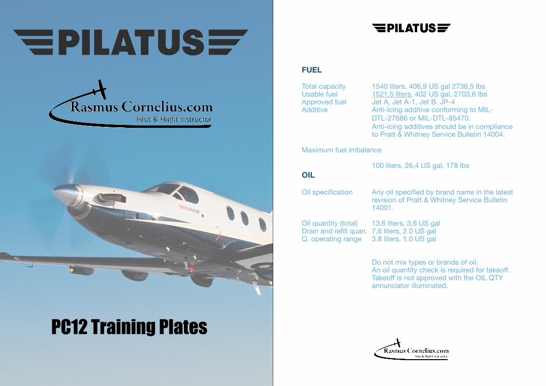
PC12 Training Plates
FUEL
Total capacity 1540 liters, 406,9 US gal 2736,5 lbsUsable fuel 1521,5 liters, 402 US gal, 2703,6 lbsApproved fuel Jet A, Jet A-1, Jet B, JP-4Additive Anti-Icing additive conforming to MIL- DTL-27686 or MIL-DTL-85470.
Anti-icing additives should be in compliance to Pratt & Whitney Service Bulletin 14004.
Maximum fuel imbalance
100 liters, 26,4 US gal, 178 lbsOILOil specification Any oil specified by brand name in the latest revision of Pratt & Whitney Service Bulletin 14001.
Oil quantity (total) 13,6 liters, 3,6 US galDrain and refill quan. 7,6 liters, 2.0 US galQ. operating range 3.8 liters, 1.0 US gal
Do not mix types or brands of oil. An oil quantity check is required for takeoff. Takeoff is not approved with the OIL QTY annunciator illuminated.
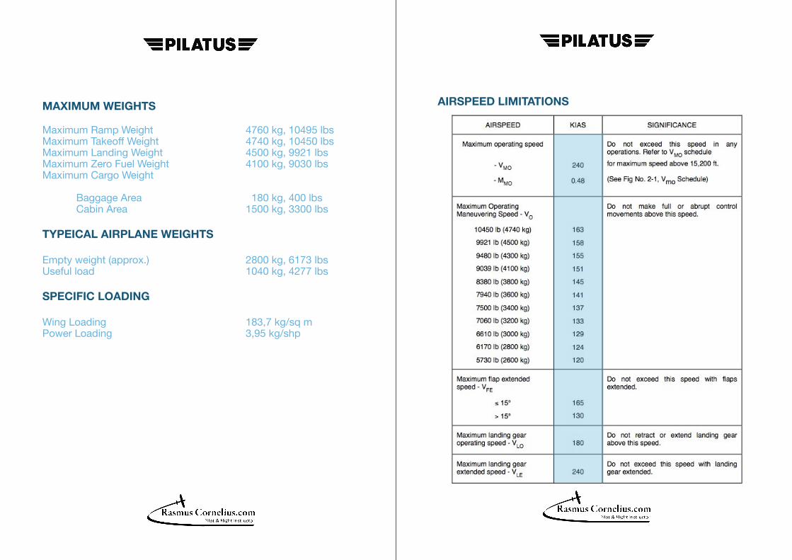
AIRSPEED LIMITATIONS MAXIMUM WEIGHTS
Maximum Ramp Weight 4760 kg, 10495 lbsMaximum Takeoff Weight 4740 kg, 10450 lbsMaximum Landing Weight 4500 kg, 9921 lbsMaximum Zero Fuel Weight 4100 kg, 9030 lbsMaximum Cargo Weight
Baggage Area 180 kg, 400 lbs Cabin Area 1500 kg, 3300 lbs
TYPEICAL AIRPLANE WEIGHTS
Empty weight (approx.) 2800 kg, 6173 lbsUseful load 1040 kg, 4277 lbs
SPECIFIC LOADING
Wing Loading 183,7 kg/sq mPower Loading 3,95 kg/shp

ENGINGE OPERATING LIMITS ENGINE OPERATING LIMITS
. (1) Torque limit applies within a range of 1000 to 1700 propeller rpm. Torque is limited to 23.9 psi below 1000 propeller rpm.
. (2) Normal oil pressure is 90 to 135 psi at gas generator speeds above 72%. With engine torque below 35.87 psi, minimum oil pressure is 85 psi at normal oil temperature (60 to 70° C). Oil pressures under 90 p si are undesirable. Under emergency conditions, to complete a flight, a lower oil pressure of 60 psi is permissible at reduced power level not exceeding 23.9 psi torque. Oil pressures below 60 psi are unsafe and require that either the engine be shut down or a landing be made as soon as possible using the minimum power required to sustain flight.
. (3) These values are time limited to 5 seconds maximum.
. (4) These values are time limited to 20 seconds maximum.
. (5) Applies over a speed range of 50.7% to 61.4% Ng rpm.
. (6) For increased service life of the engine oil, an oil temperature of between 60 to 70°is recommended.
. (7) Oil temperature limits are -40° C to 105° C with limited periods of 10 minutes at 105 to 110°C.
. (8) 100% gas generator speed corresponds to 37468 rpm. 100% power turbine speed (N1) corresponds to 29894 rpm which also corresponds to 1700 rpm propeller speed.
. (9) Takeoff power is time limited to 5 minutes.

PROPELLER OPERATING LIMITS
Maximum normal operation 1,700 rpmMaximum trasient (20 sec.) 1,870 rpmMaximum reverse 1,650 rpm Stabilized operation on the ground between 350 and 950 rpm is not permitted.
Blade Angles at Station 42 Fine Pitch 19°+/-0.1° Max. Reverse Pitch -17.5°+/-0.5° Feather 79.6°+/- 0.5 °
Minimum pitch in flight 6°
STARTER
The engine starting cycle shall be limited to the following intervals:
1. Sequence, 60 seconds OFF 2. Sequence, 60 seconds OFF 3. Sequence, 30 minutes OFF
Generator 2 is acting as a starter.
POWER CONTROL LEVER OPERATION
Power Control Lever operation aft of the idle detent is prohibited:
1. When Engine is not running. 2. During flight. Such operation may lead to loss of airplane control and total power loss. 3. When engine is control by the Manual Override System (MOR). Such operation may lead to loss of airplane control or may result in an engine/propeller overspeed condition and consequent loss of engine power. MANEUVER LIMITS
This airplane is certificated in the Normal Category. The normal category is applicable to aircraft intended for non-aerobatic operations. These include any maneuvers incidental to normal flying, stalls (except whip stalls), lazy eights, chandelles, and turns in which the bank angle does not exceed 60°.
Aerobatic maneuvers, including spins, are not approved.
FLIGHT LOAD FACTOR LIMITS
Flight load limits with flaps up +3.3 g, -1.32 g
Flight load limits with flaps down +2.0 g, -0.0 g

KIND OF OPERATION
The Pilatus PC-12 is approved for the following types of operation when the required equipment is installed and operational:
1. VFR Day 2. VFR Night 3. IFR Day incl. CAT 1 approaches, single pilot. 4. IFR Night incl. CAT 1 approaches, single pilot. 5. Flight into Known Icing Conditions.
PNEUMATIC DEICING BOOT SYSTEM
The wing and tail leading edge pneumatic deicing boot system must be activated at the first sign of ice formation anywhere on the aircraft.
The wing and tail leading edge pneumatic deicing boot system may be deactivated only after leaving icing conditions and after the aircraft is determined to be clear of ice.
MAXIMUM OPERATING ALTITUDE Maximum operating altitude 30,000 ft (9,144 m)
OUTSIDE AIR TEMPERATURE LIMITS Minimum OAT -55°C (-67°F)Maximum OAT +50°C (122°F)Operation on the ground is prohibited when the aircraft has been exposed to outside air temperatures below minus 35° C for more than 3 hours without the engine running.
CABIN PRESSERIZATION LIMITS
Maximum cabin pressure differential is 5.75 psi (400 mbar).
Pressurized landing is approved, up to 0.8 psid.
STALL WARNING / STICK PUSHER SYSTEM
Preflight function test required before takeoff.
System is required to function properly in normal mode for all flights and in ice mode for flights into known icing conditions.
TRIM SYSTEM
Stabilizer normal and alternate, and rudder trim systems must function properly for all flights.
HEATED WINDSHIELD
Left Hand and Right Hand Heated Windshields must function properly for all flights. Exception, for IFR flights conducted into no known or forecast icing conditions at least one heating zone of the windshield on the side of the pilot in command must function properly.

FIRE DETECTION SYSTEM
Preflight Function Test is required for takeoff.System must function properly for all flights.
ENGINE ICE PROTECTION
Preflight Function Test is required for takeoff.OXYGEN SYSTEM
A minimum oxygen supply of 10 minutes duration for each occupant is required for dispatch for pressurized flight above FL250.
NOTE Some National Operating Requirements may require that a larger
quantity of oxygen be carried on the aircraft.
The oxygen system shut-off valve handle in the cockpit must be selected to on prior to engine start and throughout the duration of flight.
The oxygen masks for the crew must be connected for all flights.
For aircraft with the Corporate Commuter side wall paneling, oxygen masks must be connected and properly stowed for each passenger prior to takeoff when the aircraft is to be operated above 10,000 feet.
NOTE In the executive interior configurations the oxygen masks are
permanently connected.
PNEUMATIC DEICE SYSTEM
The pneumatic deice system boots are required to be installed for all flights. Preflight function test required before takeoff and flight into known icing conditions. The system is required to function properly for flight into known icing conditions.
PROBE HEAT
Preflight function test required before takeoff. The system is required to function properly for IFR flight and flight into known icing condition.
FLAP SYSTEM CYCLE LIMITS
A flap cycle is defined as movement from 0° to 15° to 0° and from 0° to 15° to 40° to 0°. Maximum number of cycles per hour -
Up to 25°C OAT 10 25°C to 50°C OAT 8
PRIMUS APEX
The Honeywell PRIMUS APEX Integrated Avionics System for the Pilatus PC-12E – Pilot’s Guide must always be on board the aircraft.

PRIMUS APEX - AUTOMATIC FLIGHT CONTROL SYSTEM
During autopilot operation, a pilot must be seated in a pilot position with seat belt fastened.
The autopilot (AP) and yaw damper (YD) must be OFF during takeoff and landing.
Minimum engagement height after takeoff is 400 ft AGL.
With the exception of the approaches defined below, the autopilot must be disengaged below 1000 ft AGL.
For non-precision approaches (at airspeeds <150 KIAS & VS <1500 ft/min) the autopilot must be disengaged below 400 ft AGL.
For approach procedures with vertical guidance in VGP mode, the autopilot must be disengaged below 200 ft AGL.
For autopilot coupled ILS approaches up to 4° the autopilot must be disengaged below 200 ft AGL.
For approaches that do not include a co-located DME, the autopilot must be disengaged below 400 ft AGL
The system is approved for Category 1 operation (Approach mode selected).
Maximum approved glideslope angle for all coupled approaches is 4°.During normal operation do not overpower the autopilot to change pitch and roll attitude.
YAW DAMPER
Above FL200, when the yaw damper is not operating, the aircraft must be flown only in balanced flight (slip ball centered +/- 1 ball).
PRIMUS APEX – ELECTRONIC CHARTS
Electronic Charts provide supplemental situation awareness and do not allow “blind taxi” procedures or navigation by use of the charts.
The pilot shall remain responsible for taxiing by external visual reference and airborne navigation by use of the primary navigation instruments.
The position accuracy of the aircraft symbol on the charts can decrease in the case of insufficient GPS signal reception or a GPS sensor failure.
The Electronic Charts do not replace the published paper copies of charts, the paper charts must remain available as a backup reference for chart data.
Implementation of Electronic Charts does not constitute operational approval.

RUNWAYS Aircraft operation is limited to dry and wet paved runways and surfaces with a minimum surface hardness of 8 kg/cm2.
Maximum airfield elevation is 14000 feet.
FLIGHTS OVER WATER
Flights over an expanse of water must be performed within the gliding range of land.
MAXIMUM WIND
Maximum allowed wind value limits:
During taxiing 50 kts (26 m/s)
Take-off and landing Tailwind 10 kts ( 5 m/s) Crosswind Flap 0° 30 kts (15 m/s) Flap 15° 25 kts (13 m/s) Flap 30° 20 kts (10 m/s) Flap 40° 15 kts ( 8 m/s)
For wind strengths greater than 30 m/s (53 kts) the aircraft must be parked in an area protected from the wind.
NORMAL PROCEDURES SPEEDS
Rotation Speed (Vr) Flap 15° 82 kts Flap 30° 76 kts
Airspeeds are based on a maximum takeoff weight of 10,450 lb (4,740 kg) at sea level under ISA standard day conditions.
Recommended Climb SpeedFlaps retracted 140 ktsPusher Ice Mode
Best Rate (Vy), Flaps 0° Sea level 130 kts 5,000 ft 125 kts 10,000 ft 125 kts 15,000 ft 125 kts 20,000 ft < 120 ktsMaximum Climb (Vx)
Best Angle 120 kts
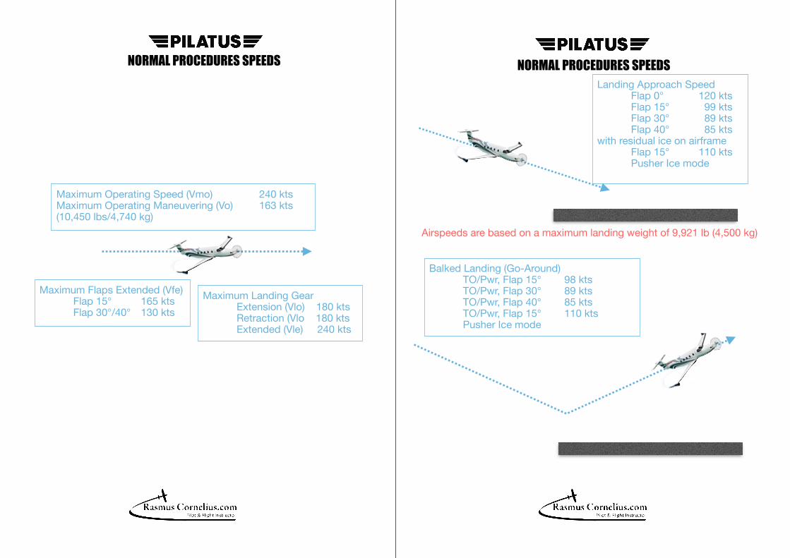
NORMAL PROCEDURES SPEEDSNORMAL PROCEDURES SPEEDS
Maximum Operating Speed (Vmo) 240 ktsMaximum Operating Maneuvering (Vo) 163 kts(10,450 lbs/4,740 kg)
Maximum Flaps Extended (Vfe) Flap 15° 165 kts Flap 30°/40° 130 kts
Maximum Landing Gear Extension (Vlo) 180 kts Retraction (Vlo 180 kts Extended (Vle) 240 kts
Landing Approach Speed Flap 0° 120 kts Flap 15° 99 kts Flap 30° 89 kts Flap 40° 85 ktswith residual ice on airframe Flap 15° 110 kts Pusher Ice mode
Balked Landing (Go-Around) TO/Pwr, Flap 15° 98 kts TO/Pwr, Flap 30° 89 kts TO/Pwr, Flap 40° 85 kts TO/Pwr, Flap 15° 110 kts Pusher Ice mode
Airspeeds are based on a maximum landing weight of 9,921 lb (4,500 kg)
Short Overview
Flight Controls Ailerons
- Controlled by cables - Flettner tab to aid in reducing control forces - Electrically controlled trim tab - Trim not controlled by the autopilot
Rudder
- Controlled by cables - Electrically controlled trim tab - Trim can be controlled by the autopilot
Elevator
- Controlled by cables - Trim provided by positioning Horizontal Stabilizer - Two electrical trim motors - One controlled by pilots - One Controlled by Autopilot and alternate control for pilots

Short Overview
Flaps Positions
- 0°, 15°, 30°, 40°
Power Drive Unit
- Single Electric Drive Unit, which drives screw actuators at the flaps, through a flexible shaft
Failures
- Flap asymmetry or twist, will receive Pusher Safe Mode CAS - In the ‘safe’ mode the stick pusher will operate at the flap 0° flap speed setting - If a failure is detected, the Flap Control and Monitoring Unit (FCWU) disconnects the power to the PDU and the CAS will show a Flaps caution
Short Overview
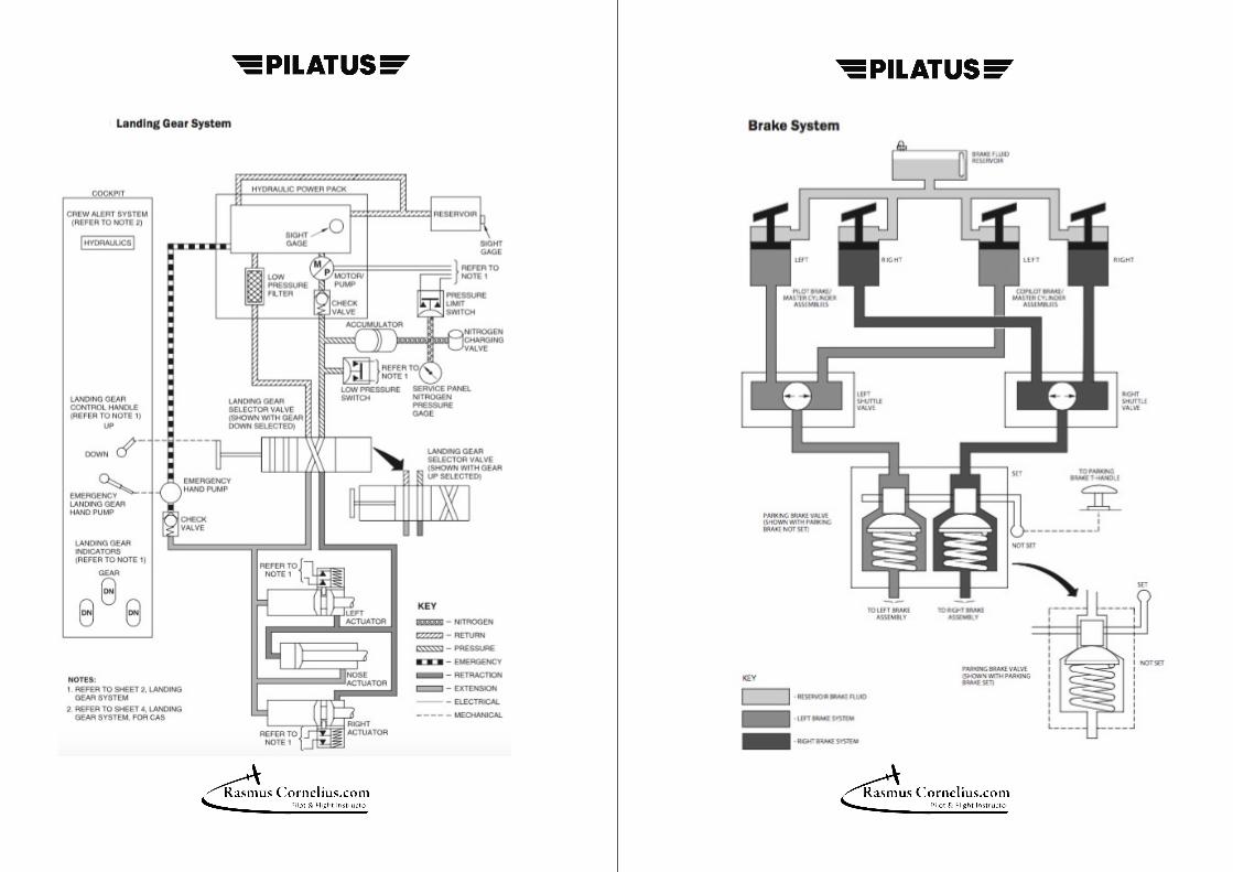
Landing Gear Operation
- Landing Gear extension and retraction, controlled by hydraulic pressure - Gear held in the up position by hydraulic pressure - Gear is held down by mechanical locks and a over center joint on the nose gear - Proximity sensors for up and down limits for each gear
Failure
- Loss of hydraulic pressure while gear is up, nitrogen accumulator will hold gear in the up position for 200 minutes - Emergency landing gear hand pump is used to assist in free fall emergency landing gear deployment (airspeed less than 110)
- Hydraulic CAS for: - Low hydraulic pressure - Pump operation in flight greater than 2 minutes - After landing, pump operated more than 6 times in flight
Flight Alerting System
- Gear handle in UP position, aural warning: - Airspeed less than 130, PCL idle - Flaps set to 30° or 40° - Radar altitude of less than 200 and torque less than 10 psi
Short Overview
Air / Ground Operation
- Aircraft air/ground status determined by an interface with the Modular Avionics Unit (MAU) through a combination of: - LH main gear proximity switch - RH main gear proximity switch - Radar Altimeter - Calibrated airspeed (ADAHRS) - If MAU determines a disparity in a sensor, it can still determine correct status through the other sensors - If MAU cannot determine the correct status in a disparity: - MAU will go to Air/Ground Fail - Air/Ground Fail CAS - Air/Ground state will default to Air
Short Overview
Brakes Operation
-Independent left and right main landing gear hydraulic brakes - Controlled by either the pilot's or copilot's toe brakes - Pilot applying the greater pressure controls that brake - Parking brake, when engaged, holds in pressure applied to the brakes - Each brake has a brake wear indicator pin

Short Overview
Doors and Exit Forward Cabin Door
- Door operation from either inside or outside - Secured by six locking pins, which can be visually checked from within the cabin - Emergency exit, which must be accessible at all times - Passenger Door CAS when door is open or not closed properly
Cargo Door
- Normally opened from the outside, emergency handle on the inside - Secured by locking pins and hooks, can be visually verified from the outside - Not a required emergency exit - Electric wench aids in closing, power from the HOT BAT BUS - Cargo Door CAS when door is open or not closed properly
Emergency Window Exit
- Required emergency exit - Quick opening from either inside or out - No CAS if window is open
Short Overview
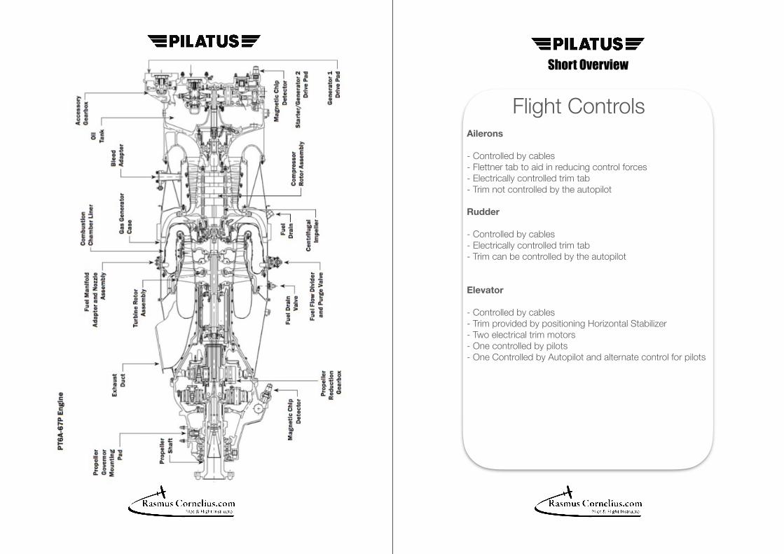
Engine Operation
- Light weight, reverse flow, free turbine engine - Air enters the back of the engine, compressed into the combustion chamber, ignited, then directed through the compressor and power turbines, before exiting the exhaust ducts at the front of the engine
Inertial Separator
- Electrically controlled door - When open, allows FOD in the air intake flow path to pass out the back of the inlet duct - Opened by a INERT SEP switch on the pilot's lower right panel - Used during Icing and FOD conditions
Engine Fire
- Stainless steel tube filled with helium, wrapped around the outside of the engine - Engine Fire CAS - There is an engine fire, which is sensed by the steel tube overheating and tripping a sensor - Fire Detector CAS - There is a fault with the fire sensor system
Short Overview
Engine Controls Power Control Lever (PCL)
- PCL selects required engine power (Ng) and also propeller pitch in reverse - Direct linkage to the Fuel Control Unit (FCU) - PCL has an idle detent, lifting action required to move into ground operating ranges - Reverse range adjusts pitch and power, limited by the Nf governor
Manual Override Level (MOR)
- Directly controls engine power, by the fuel metering valve, in the event of an FCU or PCL failure - Possible to exceed engine limits if operated too fast - When in use, torque limiter and Nf governor are inoperative
Condition Lever
- Three possible positions, Ground idle, Flight idle, Cut-off/Feather - Flight idle will ensure sufficient bleed air for pressurization with the PCL at idle - Cut-off/Feather mechanically stops fuel and electrically feathers the propeller
Short Overview
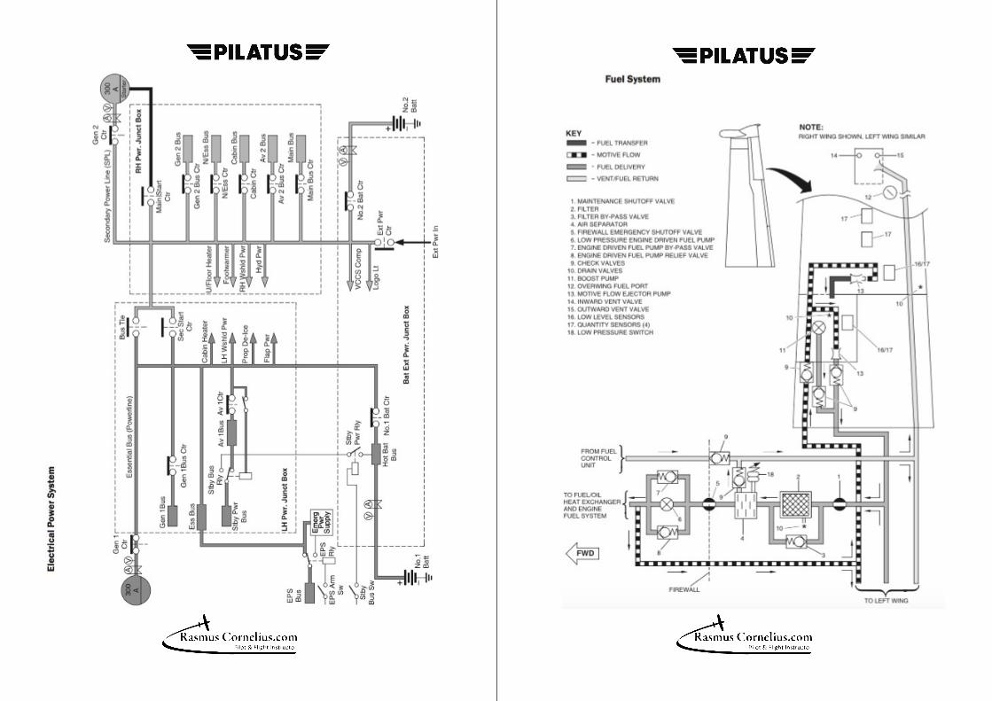
Fuel System Operation
- Two integral wing tanks, with over wing refill points for each tank - Anti-icing agent "Prist" must be added to fuel for flights below 0° C - Fuel/Oil Heat Exchange, heats fuel before entering the FCU, no pilot interaction - FCU determines how much fuel to deliver to the engine, excess fuel returns to each tank
Pumps
- Motive flow pumps (solid state venturi) move fuel out of each tank - Electric boost pumps in each tank used for engine start, fuel imbalances and low pressure - Two engine driven fuel pumps (Low and High Pressure), Electric boost pumps can maintain pressure in the event of a low pressure pump failure
Filters
- Two fuel filters, automatic bypass in the event of blockage - No cockpit indication in the event of a filter bypass
Continues…
Short Overview
Fuel System … Continued
Pilot Controls
- Fuel Reset softkey in the Fuel window re-datums total fuel quantity and resets fuel used - Fire Wall Shutoff allows pilot to shut off fuel flow, before it enters the engine compartment - Electric Boost Pumps controlled by an AUTO/ON switch for each pump - AUTO will allow boost pumps to turn on in the event of a low pressure or tank imbalance
Indication
- Pump caption - Either Boost Pump on - LH or RH Fuel Low CAS - Tank with less than 20 US gallons - Fuel Pressure Low CAS - Low fuel system pressure - Fuel Quantity Fault CAS - Unable to determine fuel quantity - Fuel Imbalance CAS - Fuel imbalance of more than 178 lbs between tanks (takeoff prohibited) - Fuel Balance Fault CAS- Auto balancing unsuccessful
Short Overview
Oil System Operation
- Oil delivered by an engine driven pressure pump and returned by scavenger pumps - Oil cooled through an oil cooler and the Fuel/Oil Heat Exchange
Pilot Indication and Control
- Oil quantity checked through a sight gauge in the engine compartment - Engine start not recommended when oil below green range on the sight gauge - Engine Oil Level CAS - Oil quantity too low for start - Engine Chip CAS - Foreign matter in the oil system
Short Overview
Fuel Control Unit
Operation
- Mechanically meters fuel delivered to the engine from the fuel tanks, based on Ng, Compressed air (P3), PCL position, Condition level, and MOR - No Electrical connections
Torque limiter
- Monitors torque and limits power sets to 44.34 PSI at sea level - When torque exceeds 44.34 PSI, torque limiter bleeds off compressed air from the FCU (Py), which causes the FCU to decrease fuel flow
Short Overview
Starter and Ignition
Starter
- When the starter switch is engaged, Generator 2 energized as a starter - Battery 2 provides power to the starter - Battery 1 powers the essential systems initially, then provides power to the starter - The starter will say engaged until Ng reaches 50% or 80 seconds after the start sequence began - The start can also be interrupted by an interrupt switch, at any time
Ignition
- The Ignition Switch has two positions, On or Auto - When in Auto, the igniters will turn on when the ITT is less than 500° C and the Ng is greater than 10%

Short Overview Short Overview
Propeller Operation
- Four blade variable pitch, full feathering propeller - Driven by the engine power turbine, through the reduction gearbox - Each blade incorporates an electric deice boot
Propeller Pitch
- Propeller moved to the feather position by feathering spring and a counterweight on each blade - Propeller moved to a fine pitch, and reverse pitch, by oil entering the propeller hub under pressure from the engine
Constant Speed Unit (CSU)
- Mechanical governor which regulates the amount of oil begin sent to the propeller hub - Limits propeller speed to 1700 RPM - No interaction required for the pilot
Overspeed Governor
- Works the same way as the CSU, excepts limits propeller RPM to 1802
Continues…
Propeller… Continued Nf Governor
- Limits propeller RPM to 1853 RPM - Limits propeller speed by bleeding off Py air from the FCU, which makes the FCU decrease fuel flow to the engine - Also used to limit propeller speed in reverse to 1650 RPM
Reverse Operations
- When the PCL is moved past the idle detent, it directly controls the amount of oil begin delivered to the propeller hub - As the PCL is moved further aft, more oil enters the hub, moving the Propeller blades to a reverse condition
De-ice
-The electric de-icing boots are controlled by a Prop Heat switch on the Ice Protection panel -When the electric heat is turned on, a deice timer control automatically selects the de-icing blade pattern based on IOAT > 0° C - Timer in Standby (No power) 0° C to -16° C - Blades 1 and 3 on for 45 seconds / Blades 2 and 4 on for 45 seconds / 90 seconds off Below -16° C - Blades 1 and 3 on for 90 seconds / Blades 2 and 4 on for 90 seconds

Short Overview Short Overview
Electrical Batteries
-Two lead-acid or nickel-cadmium 24 volt batteries - Emergency Power Supply (EPS) 24 volt lead-acid battery
Generators
- Two 28 Volt, 300 Amp Generators
Operation
- Correct power up procedures include: - STBY BUS on (wait 30 seconds) - EPS tested and armed - Batteries on - External Power on, if required - Correct power down procedures include: - External power off - STBY BUS off - EPS off - Batteries off - Generator 2, used for starting - Generators turn on and off automatically, with each switch left on
Failures
- Single Generator failure can provided power to the system, some services automatically shed - External Power Controller monitors external power supply and disconnects external power if needed - Batteries can supply sufficient power for up to 33 minutes
- EPS will supply sufficient power to the EPS bus for 30
Environmental Control System
ECS
- Comprises of: - Air Cycle System (ACS) - Auxiliary heaters - Vapor Cycle Cooling System (VCCS) - Vent fans and flood fan
ACS
- Engine bleed air delivered to the cabin at the desired temperature - Pilots can turn the ACS off by the ACS inhibit switch or the firewall shutoff
Auxiliary heaters
- Cabin Heater used to aid in heating the cabin - The Underfloor Heater heats under floor avionics and electrical equipment - Both controlled by the MAU based on the desired temperature - The Electrical Heat/Cool inhibit switch will shut both off
Continues…
Short Overview Short Overview
Environmental Control System
… Continued
VCCS
- Uses a refrigerant gas through a compressor and evaporator circulated by a vent and flood fan to cool the cabin - The fans and compressor are turned on automatically, based on the desired temperature set by the pilot - The vent fan, which has a low and a high setting, can be turned to Auto on Low by a switch - The flood fan can be turned off by the Flood Fan inhibit switch - The entire VCCS system can be turned off by the Electrical Heat/Cool inhibit switch
Indication/Warning
- ACS Low Inflow CAS - ACS shutdown down due to an overpressure or over temperature condition or unable to achieve the required cabin pressure - ECS Fault CAS - ECS controller has detected a critical fault or a loss of communication with the MAU
Cabin Pressure Control System
Operation
- Controls the outflow of pressurized air to regulate cabin pressurization - CPCS comprises of: - Cabin Pressure Control Unit (CPCU) - Electrically Driven Outflow Valve - Pneumatic Safety Pressure Relief Valve - Negative Pressure Relief Valves
CPCU
- Through sensors with the MAU, controls the outflow valve to adjust the cabin pressure - Desired cabin altitude automatically determined by the MAU, but can be manually entered by the pilot
Outflow Valve
- Butterfly valve controlled by two electric motors, which receives position settings from the CPCU - In emergencies can be controlled manually by a Cabin Climb/Descent switch
Continues…
Short Overview Short Overview
Cabin Pressure Control System
… Continued
Pneumatic Safety Pressure Relief Valve
- Completely independent of all other systems - Reduces differential pressure between the atmosphere and cabin if the max value is exceeded - Will also open if there is a negative differential
Negative Pressure Relief Valves
- Located in the rear bulkhead, provide secondary means to relieve a negative pressure situation
Oxygen System Operation
- Emergency system to provide oxygen to crew and passengers - Comprises of: - Pilot and copilot quick-donning, diluter-demand masks - Constant flow passenger masks - Composite oxygen cylinder
Crew Masks
- Permanently connected to outlets in the cockpit sidewall - Switch for 100% Oxygen flow (in event of fire) or diluter demand - Each mask has a built in microphone for communication - The Mic/Mask switch must be in Mask to communicate
Passenger Masks
- Cockpit three position switch (Auto, On, Off) controls flow of oxygen - In Auto, oxygen will flow to masks above a cabin altitude of 13,500 - Mask for each seat and one in the lavatory
Oxygen Bottle
- Oxygen level, mounted to the right of the center console, controls main shutoff for the bottle - Should be charged to 1850 PSI - Relief valve rupture disc, will discharge contents of the bottle when the pressure reaches 2775 PSI
Short Overview Short Overview
Pitot Static System
Pitot
- Heated pitot heads installed under each wing - Pressure sensed through the pitot heads, sent to the ADAHRS Channels A and B
Static
- Dual heated static ports installed on each side of the rear fuselage - Static pressure sensed by the static ports sent to the ADAHRS Channels A and B
Heating
- Both static ports and pitot tubes are electrically heated - Electric heat controlled by the Probes switch on the ice protection panel
Shaker/Pusher System
Operation
- Aircraft equipped with a stick shaker-pusher system to prevent inadvertent stall entry - System contains two Angle-of-Attack (AOA) sensors connected to two computers - One computer can activate stick shaker, two required for pusher activation
Indications and Control
- The Dynamic Speed Bug (DSB) is located adjacent to the airspeed indicator and is represented a green arrow - The DSB displays filter AOA and can be used for corrected approach speeds and stall awareness - Visual and aural "Stall" warnings during shaker and pusher activation - Each control yoke is equipped with a pusher interrupt switch, stick shaker activation cannot be interrupted
Ice Protection
- When in icing conditions, or if residual ice is on the airframe, the Inertial Separator and Prop Heat must be on - When these systems are activated the stick shaker and pusher system divert to pusher ice mode (with a Pusher Ice Mode advisory) - In pusher ice mode the shaker and pusher actuating points are shifted down 8° AOA
Short Overview
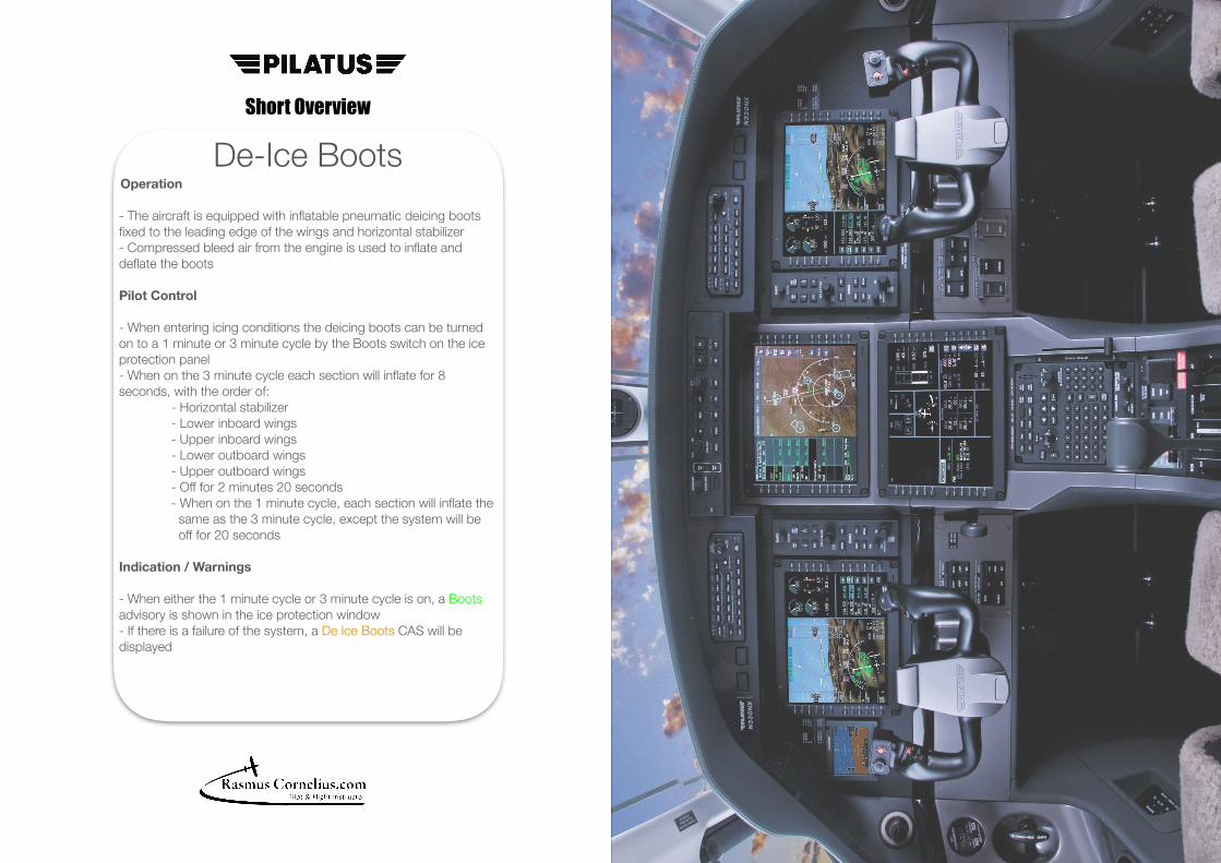
De-Ice Boots Operation
- The aircraft is equipped with inflatable pneumatic deicing boots fixed to the leading edge of the wings and horizontal stabilizer - Compressed bleed air from the engine is used to inflate and deflate the boots
Pilot Control
- When entering icing conditions the deicing boots can be turned on to a 1 minute or 3 minute cycle by the Boots switch on the ice protection panel - When on the 3 minute cycle each section will inflate for 8 seconds, with the order of: - Horizontal stabilizer - Lower inboard wings - Upper inboard wings - Lower outboard wings - Upper outboard wings - Off for 2 minutes 20 seconds - When on the 1 minute cycle, each section will inflate the same as the 3 minute cycle, except the system will be off for 20 seconds
Indication / Warnings
- When either the 1 minute cycle or 3 minute cycle is on, a Boots advisory is shown in the ice protection window - If there is a failure of the system, a De Ice Boots CAS will be displayed