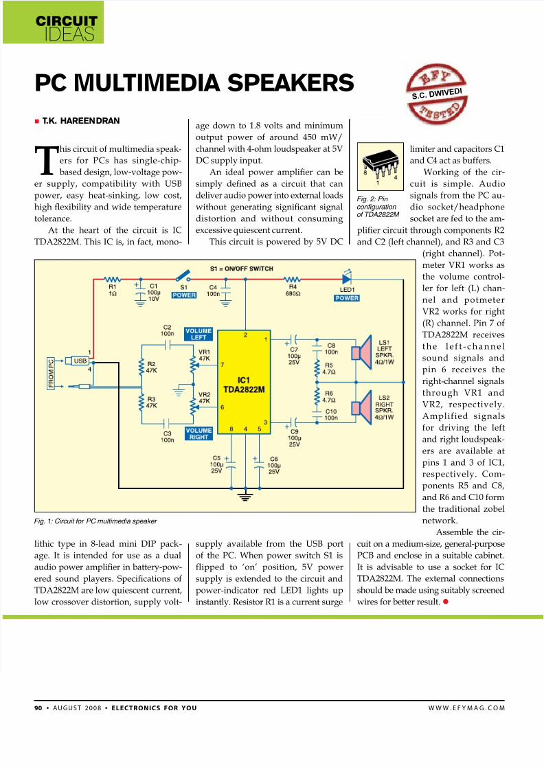
circuit ideas 90 • august 2008 • electronics for you www.efymag.com limiter and capacitors C1 and C4 act as buffers. Working of the cir- cuit is simple. Audio signals from the PC au- dio socket/headphone socket are fed to the am- plier circuit through components R2 and C2 (left channel), and R3 and C3 (right channel). Pot- meter VR1 works as the volume control- ler for left (L) chan- nel and potmeter VR2 works for right (R) channel. Pin 7 of TDA2822M receives the left-channel sound signals and pin 6 receives the right-channel signals through VR1 and VR2, respectively. Amplified signals for driving the left and right loudspeak- ers are available at pins 1 and 3 of IC1, respectively. Com- ponents R5 and C8, and R6 and C10 form the traditional zobel network. Assemble the cir- cuit on a medium-size, general-purpose PCB and enclose in a suitable cabinet. It is advisable to use a socket for IC TDA2822M. The external connections should be made using suitably screened wires for better result. T .K. Hareendran PC Mul TiMedia SPeaKerS s.c.d w i v e d i T his circuit of multimedia speak- ers for PCs has single-chip- based design, low-voltage pow- er supply, compatibility with USB power, easy heat-sinking, low cost, high exibility and wide temperature tolerance. At the heart of the circuit is IC TDA2822M. This IC is, in fact, mono- lithic type in 8-lead mini DIP pack - age. It is intended for use as a dual audio power amplier in battery-pow- ered sound players. Specications of TDA2822M are low quiescent current, low crossover distortion, supply volt- age down to 1.8 volts and minimum output power of around 450 mW/ channel with 4-ohm loudspeaker at 5V DC supply input. An ideal power amplier can be simply dened as a circuit that can deliver audio power into external loads without generating signicant signal distortion and without consuming excessive quiescent current. This circuit is powered by 5V DC supply available from the USB port of the PC. When power switch S1 is flipped to ‘on’ position, 5V power supply is extended to the circuit and power-indicator red LED1 lights up instantly. Resistor R1 is a current surge RIGHT Fig. 1: Circuit for PC multimedia speakerFig. 2: Pin configuration of TDA2822M