Embed Size (px)
Citation preview

the antenna solutions provider
SPECIFICATION
Part No. : PC-2908-09 Product Name : TheStripe™ Penta-band
GSM 850/900/1800/1900 & UMTS/WCDMA 2100 MHz 80mm*30mm PCB Antenna for Murata GSC Connections
Features : 119mm long, 0.81mm diameter Miniature Co-axial Cable Murata GSC (Compatible) Connector Tested in Freespace ROHS Compliant
Photo :
REVISION STATUS
Version Date Page Revision Description Prepared Approved
01 May 24th 2007 All New format TW Product Centre Ronan Quinlan
the antenna solutions provider
Contents
1.0 Introduction 3
2.0 Key Antenna Performance Indicators 3
3.0 Mechanical Specifications 4
4.0 Placement 4
5.0 Electrical Characteristics Charts 5
6.0 Environmental Conditions and Reliability 7
7.0 Test Setup and Detailed Results 8
8.0 Packaging 19
9.0 Cable and Connector Drawings 20
the antenna solutions provider
1.0 Introduction This high performance, low profile, PCB antenna is based on smart TheStripe™ antenna technology. It consists of a PCB antenna and mini coaxial cable. The product is a high gain Penta-band 850/900/1800/1900/2100 antenna suitable for worldwide GSM, UMTS and WCDMA applications. The product should be tested in freespace conditions connected to the client’s cellular device. It is designed for connection to Murata GSC receptacles. Further optimization can be done upon receipt of the client’s device at a local Taoglas facility.
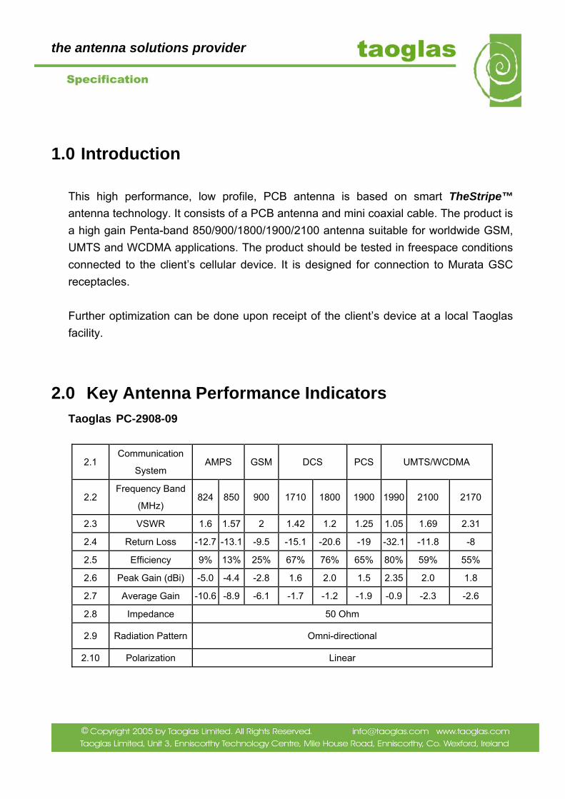
2.0 Key Antenna Performance Indicators Taoglas PC-2908-09
2.1 Communication
System AMPS GSM DCS PCS UMTS/WCDMA
2.2 Frequency Band
(MHz) 824 850 900 1710 1800 1900 1990 2100 2170
2.3 VSWR 1.6 1.57 2 1.42 1.2 1.25 1.05 1.69 2.31
2.4 Return Loss -12.7 -13.1 -9.5 -15.1 -20.6 -19 -32.1 -11.8 -8
2.5 Efficiency 9% 13% 25% 67% 76% 65% 80% 59% 55%
2.6 Peak Gain (dBi) -5.0 -4.4 -2.8 1.6 2.0 1.5 2.35 2.0 1.8
2.7 Average Gain -10.6 -8.9 -6.1 -1.7 -1.2 -1.9 -0.9 -2.3 -2.6
2.8 Impedance 50 Ohm
2.9 Radiation Pattern Omni-directional
2.10 Polarization Linear
the antenna solutions provider
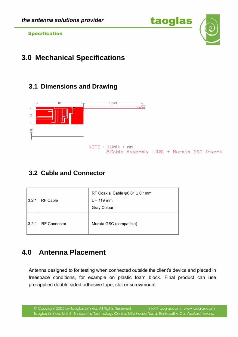
3.0 Mechanical Specifications
3.1 Dimensions and Drawing
3.2 Cable and Connector
4.0 Antenna Placement
Antenna designed to for testing when connected outside the client’s device and placed in freespace conditions, for example on plastic foam block. Final product can use pre-applied double sided adhesive tape, slot or screwmount
3.2.1 RF Cable
RF Coaxial Cable ψ0.81 ± 0.1mm
L = 119 mm
Gray Colour
3.2.1 RF Connector Murata GSC (compatible)
the antenna solutions provider
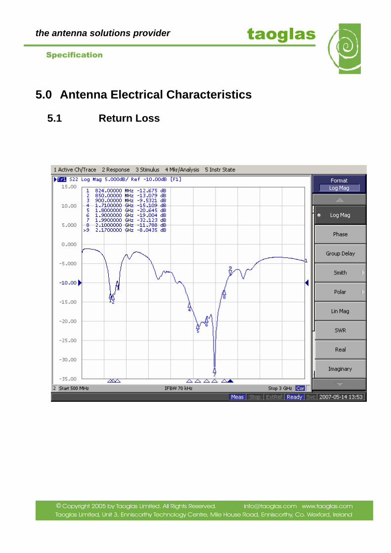
5.0 Antenna Electrical Characteristics
5.1 Return Loss

the antenna solutions provider
5.2 VSWR

the antenna solutions provider
6.0 Environmental Conditions and Reliability
6.1 Environmental Conditions
2.1.1 Operation Temperature -20°C to + 65°C
2.1.2 Storage Temperature -30°C to + 75°C
2.1.3 Relative Humidity 40% to 95%
6.2 Reliability
Test Items Procedure Requirement
Thermal Shock
Starting at -40 for 30minutes and then cycled to +85
to remain 30minutes (a complete cycle).
To repeat 5 complete cycles.
(Refer to IEC 68-2-14 Method Na)
1. The value of return loss must be within
product specifications after this test.
2. No physical deformation should be evident.
Storage
Temperature
(Cold)
Samples must be put into -30°C chamber for 72
hours and samples shall be powered during test.
(Refer to IEC 68-2-1 Method Aa)
1. The value of return loss must be within
product specifications after this test.
2. No physical deformation should be evident.
Storage
Temperature
(Dry Heat)
Samples must be put into +75°C chamber for 72
hours and samples shall be powered during test.
(Refer to IEC 68-2-1 Method Ba)
1. The value of return loss must be within
product specifications after this test.
2. No physical deformation should be evident.
Operating
Temperature
(Cold)
Samples must be put into -20°C chamber for 2
hours and samples shall be powered during test.
(Refer to IEC 68-2-1 Method Aa)
1. The value of return loss must met specification
during test/after test
2. No mechanical defects after test.
Operating
Temperature
(Dry Heat)
Samples must be put into +65°C chamber for 72
hours and samples shall be powered during test.
(Refer to IEC 68-2-1 Method Ba)
1. The value of return loss must met specification
during test/after test
2. no mechanical defects after test.
the antenna solutions provider
7.0 Antenna Test Procedures and Setup
7.1 Test Procedure for VSWR/Return Loss
7.1.1 STEP 1 Route Cable in Correct Position
7.1.2 STEP 2 Connect Antenna to Module
Connect feed-line to network analyzer
7.1.3 STEP 3 Assemble Antenna in Correct Position on Isolated Foam Block
the antenna solutions provider
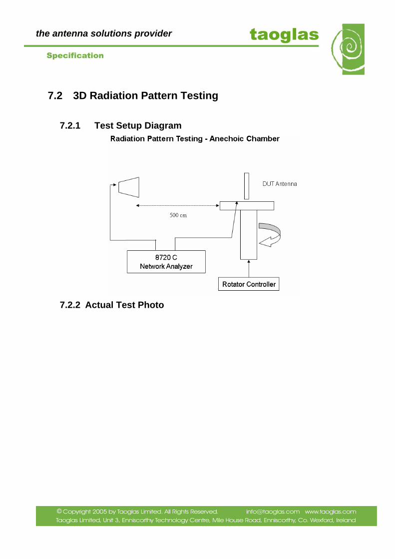
7.2 3D Radiation Pattern Testing
7.2.1 Test Setup Diagram
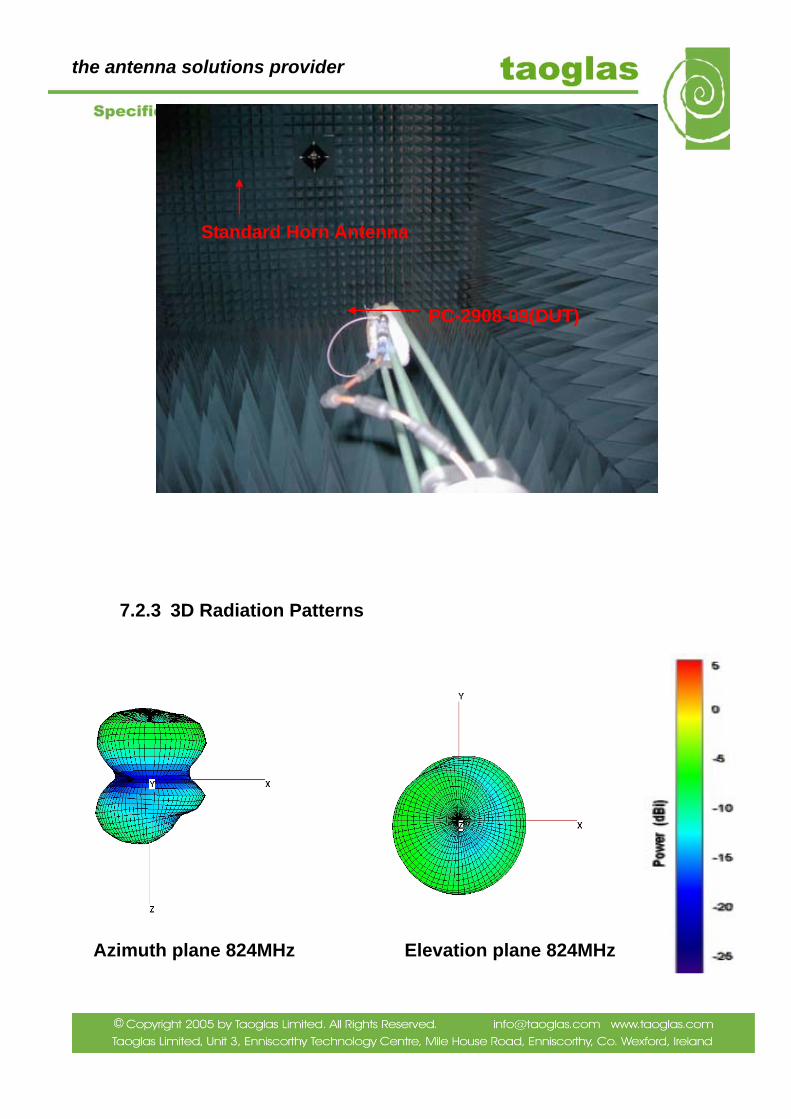
7.2.2 Actual Test Photo
the antenna solutions provider
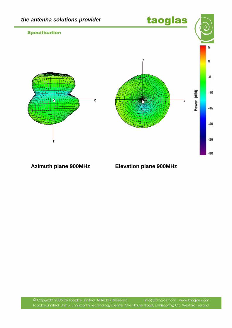
7.2.3 3D Radiation Patterns
Azimuth plane 824MHz Elevation plane 824MHz
Standard Horn Antenna
PC-2908-09(DUT)
the antenna solutions provider
4
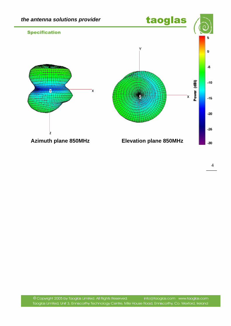
Azimuth plane 850MHz Elevation plane 850MHz
the antenna solutions provider
Azimuth plane 900MHz Elevation plane 900MHz
the antenna solutions provider
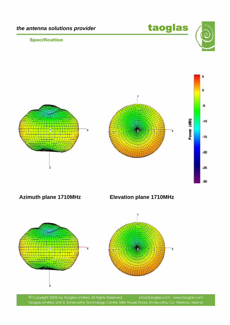
Azimuth plane 1710MHz Elevation plane 1710MHz
the antenna solutions provider
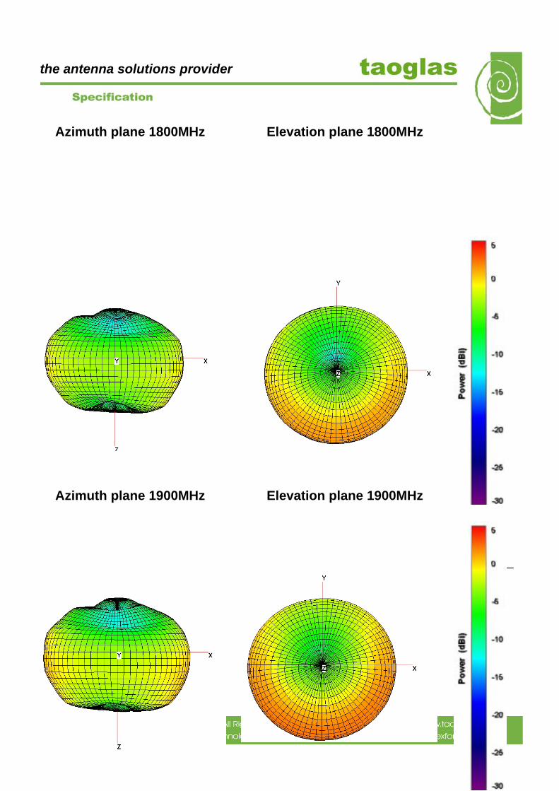
Azimuth plane 1800MHz Elevation plane 1800MHz
Azimuth plane 1900MHz Elevation plane 1900MHz
6
the antenna solutions provider
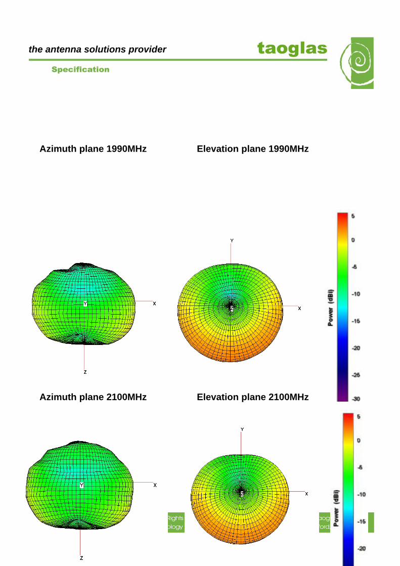
Azimuth plane 1990MHz Elevation plane 1990MHz
Azimuth plane 2100MHz Elevation plane 2100MHz
the antenna solutions provider
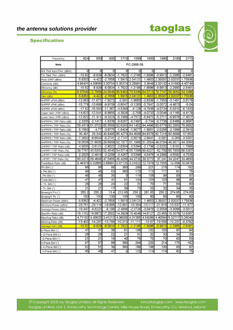
7.2.4 3D CHAMBER TESTING – TABULAR RESULTS
PC-2908-09
8
Azimuth plane 2170MHz Elevation plane 2170MHz
the antenna solutions provider
the antenna solutions provider
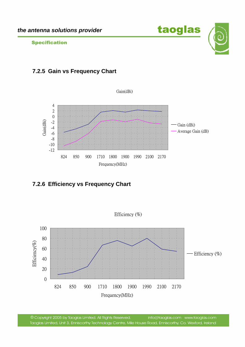
7.2.5 Gain vs Frequency Chart
7.2.6 Efficiency vs Frequency Chart
Efficiency (%)
0
20
40
60
80
100
824 850 900 1710 1800 1900 1990 2100 2170
Frequency(MHz)
Eff
icie
ncy(
%)
Efficiency (%)
Gain(dBi)
-12
-10
-8
-6
-4
-2
0
2
4
824 850 900 1710 1800 1900 1990 2100 2170
Frequency(MHz)
Gai
n(dB
i)
Gain (dBi)
Average Gain (dB)
the antenna solutions provider
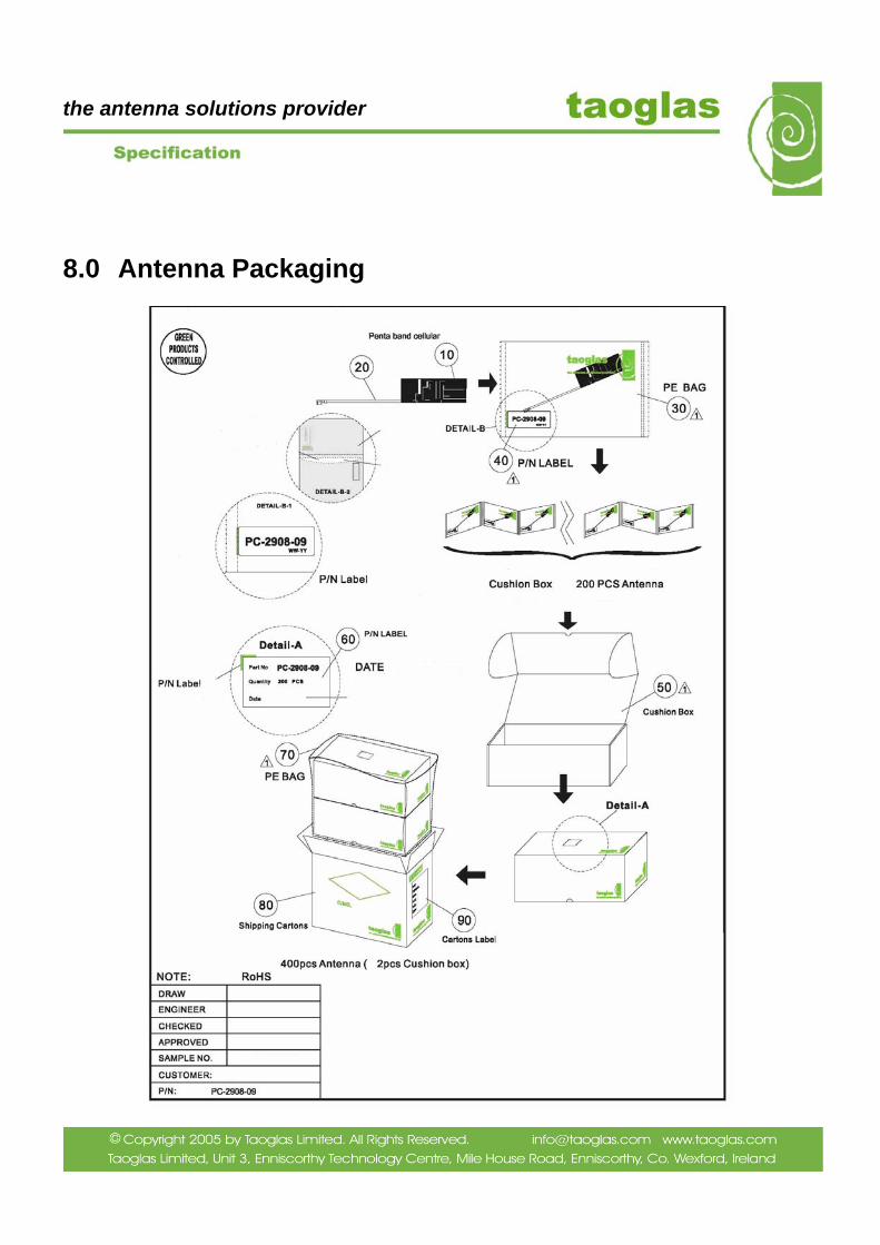
8.0 Antenna Packaging

the antenna solutions provider
9.0 Cable and Connector Drawings
0.81mm Outside Diameter Cable Specification

the antenna solutions provider
Murata GSC Connector (Compatible)