Embed Size (px)
Citation preview
PB2006-100660
\\\ 11\\11 \\1\11\1\ \11\1\ \1\\\\ \\i\
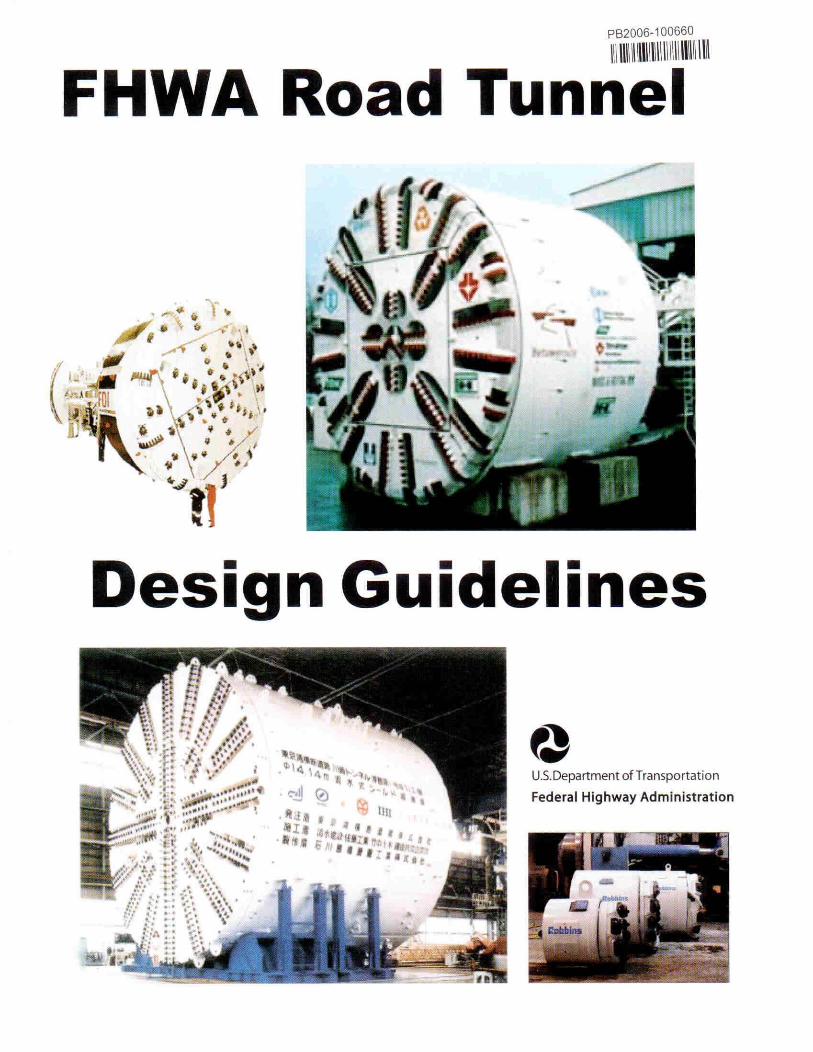
FHWA Road Tunnel
Design Guidelines
U.5.Department ofTransportation
Federal Highway Administration
Notice
This documenl is disseminaled under the sponsorship ()/Ihe Us. Department ()!"Transportationin the interest ofin/orma/ion exchonge. The Us. Govemment assumes no liability/or the use 0/the information conwined in lilis documelll.
The Us. Government does not endorse products or mam!facturers. Trademarks ormwm/aclllrers' names appear in this reporl onlv because Ihey are considered essential to theobjeClive ofthe document.
Quality Assurance Statement
The Federal Highway Administration (FHWA) provides high-qualit)' information to serveGovemment. indusli)', and the public in a manner that promotes public underswnding.Standards and policies are used to ensure and maximi~e the quali(I'. objectivity. utility, andintegritv 0/ its in/ormation. FHWA periodical(v re\'iell's qualit)' issues and adjusts its programsand processes to ensure continuous quality improvement.
RErROOlCEDor; NJIS,l,.S.l)rpullnrnlllfConllnn'Cf - - •'~fNlnal Ttchnk"al Inrorm:uion S<-n inS"rlnl:firkl. \ir;;ni. 22161
PROTECTED UNDER INTERNA TIONAL COPYRIGHTALL RIGHTS RESERVED
NATIONAL TECHNICAL INFORMATION SERVICEU.S. DEPARTMENT OF COMMERCE
FI-IIVA Road TUJlnel Design Guide/files JWIIICflV. 2004
~"" l.,[ S C(·j:::(Jttrr~en" ,'"::1 fr:YHq:0"fa1Io....'{.,. Federal Highway Administratlofl
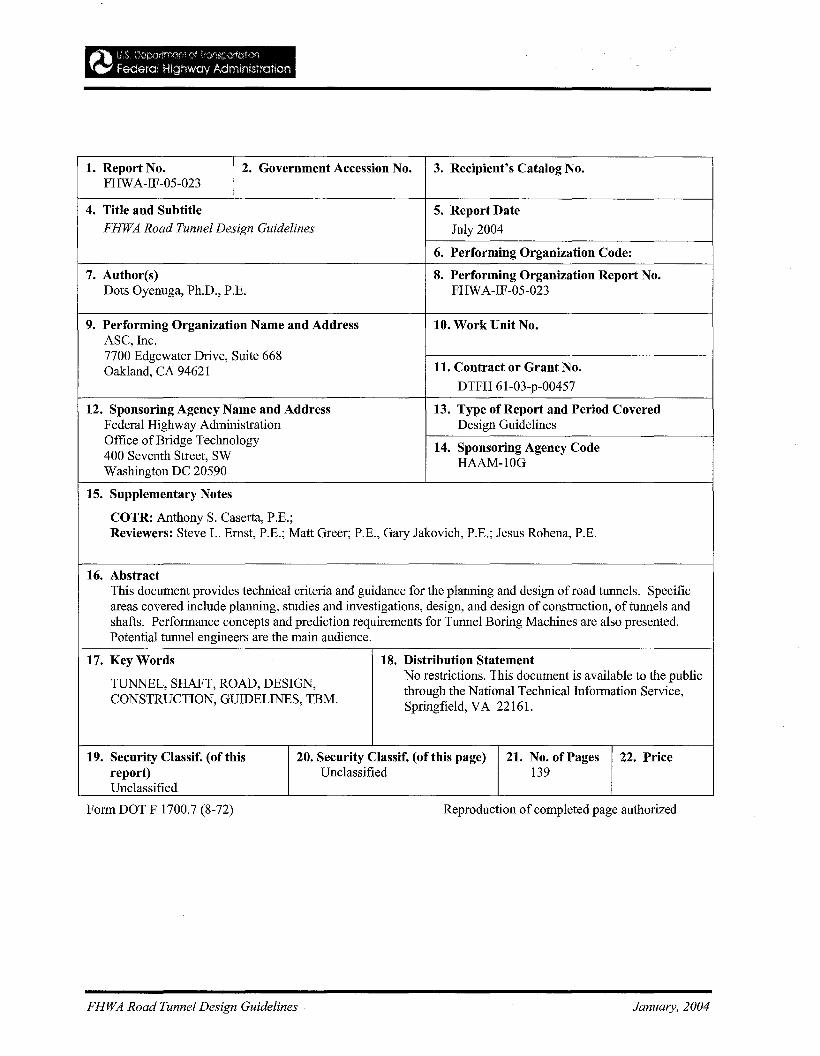
1. Report No. 2. Government Accession No. 3. Recipient's Catalog No.FHWA-IF-05-023
4. Title and Snbtitle 5. Report DateFHWA Road Tunnel Design Guidelines July 2004
6. Performing Organization Code:
7. Author(s) 8. Performing Organization Report No.Dots Oyenuga, Ph.D., P.E. FHWA-IF-05-023
9. Performing Organization Name and Address 10. Work Unit No.ASC, Inc.7700 Edgewater Drive, Suite 668
11. Contract or Grant No.Oakland, CA 94621DTFH 6l-03-p-00457
12. Sponsoring Agency Name and Address 13. Type of Report and Period CoveredFederal Highway Administration Design GuidelinesOffice of Bridge Technology 14. Sponsoring Agency Code400 Seventh Street, SW HAAM-10GWashington DC 20590
15. Supplementary Notes
COTR: Anthony S. Caserta, P.E.;Reviewers: Steve L. Ernst, P.E.; Matt Greer; P.E., Gary Jakovich, P.E.; Jesus Rohena, P.E.
16. AbstractThis document provides technical criteria and guidance for the planning and design of road tunnels. Specificareas covered include planning, studies and investigations, design, and design of construction, of tunnels andshafts. Performance concepts and prediction requirements for Tunnel Boring Machines are also presented.Potential tunnel engineers are the main audience.
17. KeyWords 18. Distribution Statement
TUNNEL, SHAFT, ROAD, DESIGN,No restrictions. This document is available to the publicthrough the National Technical Information Service,
CONSTRUCTION, GUIDELINES, TBM.Springfield, VA 22161.
19. Security Classif. (of this 20. Security Classif. (of this page) 21. No. of Pages 22. Pricereport) Unclassified 139Unclassified
Form DOT F 1700.7 (8-72)
FHWA Road Tunnel Design Guidelines
Reproduction of completed page authorized
January, 2004
FHWA Road Tunnel Design Guidelines January, 2004
ROAD TUNNEL DESIGN GUIDELINES
This Road Tunnel Design Guidelines document provides technical criteria and guidance for the planningand design of road tunnels. Specific areas covered include planning, studies and investigations, design,and design of construction, of tunnels and shafts. Performance concepts and prediction requirements forTunnel Boring Machines are also presented. It is hoped that potential tunnel engineers will obtain anoverall view of the field, and gain an appreciation of the diversity of problems that tunnel engineers mustaddress.
FHWA Road Tunnel Design Guidelines January, 2004
.~"' I):'; C,z,'l}<Jlt",.",n' 'Y 'ran"lf~11on
{~ Federal Highway Admlnlstratioo
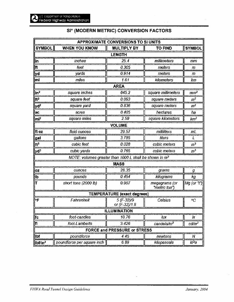
SI* (MODERN METRIC) CONVERSION FACTORS
I APPROXIMATE CONVERSIONS TO 51 UNITS IISYMBOL II WHEN YOU KNOW II MULTIPLY BY II TO FIND "SYMBOll
I LENGTH Ilin II inches II 25.4 II millimeters I[ mm I1ft II feet JI 0.305 II meters I( m IIlYd II yards II 0.914 ]1 meters II m IImi II miles II 1.61 II kilometers II km II AREA ]lin2 II square inches II 645.2 II square millimeters mm2 IIft2 II square feet II 0.093 II square meters ~ I~~ II square yard ][ 0.836 II square meters m2
lac II acres II 0.405 II hectares II haImi2 · II square miles II 2.59 II square kIlometers II k~
I VOLUME
IfI oz II fluid ounces II 29.57 II milliliters II mL
Igal II gallons JI 3.785 II liters II L ]Ift3 II cubic feet II 0.028 II cubic meters II m3 IWd3 II cubic yards II 0.765 II cubic meters II rrf3 II NOTE: volumes greater than 1000 L shall be shown in m3 JI MASS Iloz U ounces II 28.35 11 grams II g 1rIb J[ pounds II 0.454 11 kilograms II kg I
c=J1 short tons (2000 fb)II
0.907I
megagrams (or IMY(Or"1"metric ton"
I TEMPERATURE (exact degrees) I
r=J1 Fahrenheit I 5 (F-32)19 I CelsiusI~or (F-32)/1.8
I ILLUMINATION IIfc 11 foot-eandles II 10.76 II lux Il Ix
Ifl II foot-Lamberls II 3.426 II candeJalm2 II cd/ny.
I FORCE and PRESSURE or STRESS
Ilbf II poundforce II 4.45 II nellVtons II N
IIbflin2 II poundforce per square inch II 6.89 II kilopasca/s II kPa
FHWA Road Tunnel Design Guidelines January, 2004
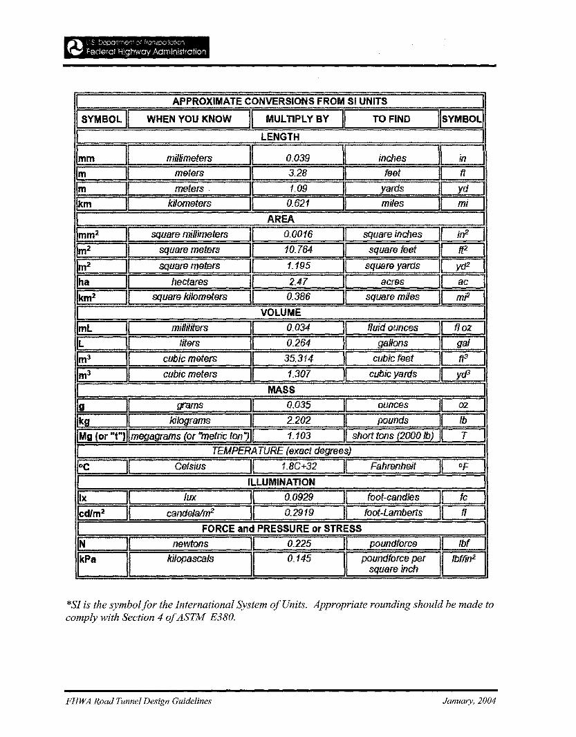
I! APPROXIMATE=CONVERSIONS FROM SI UNITS ]
'I SYMBOL II WHEN YOU KNOW II MULTIPLY BY II TO FIND IISYMBOLI
I ~~ IImm : II millimeters II 0.039 11 inches JI in I,1m II meters Il 3.28 n feet!1 ft I1m II meters . II 1.09 II yards II ydl
Ikm II kilometers II 0.621 II miles II mi ,
L=:: n. =- ::. : :..... = :A.REA.:.:::. :: :: :.:=n IImm2 II square millimeters II 0.0016 If square incheslL in2 I1m2 II square meters II 10.764 II square feet II ttl I1m2 II square meters II 1. 195 II square yards tl yeP IIha II hectares II 2.47 II acres nac IIk:m2 :JI~: ~~re ki/~rl?~!ers II La 0.~8~ I[ square miles II mP II VOLUME ]
ImL II milliliters II 0.034 II fluid ounces II fJ 02 I
(l: :: :]1 l~tefS:: :.:11 0.26~ If ~allons .. :: : ... 11 ..... gaC]
1m3 II cubic meters II 35.314 II cub/creet II ft3 I1m3 II cubic meters II 1.307 " cubic yards II yeP II MASS ::110 II grams II 0.035 II ounces If 02 I[~ii : II kilograms II *.202: ]1 pounds II Ib ]
IMg (or "tU))lmegagrams (or "metric ton.,11 1.103 II short tons (2000 Ib) UTIr: :: TEMPERAiyRE (ex~CJ~~~~es) = . ~ ~ Iloe II Celsius II 1.BC+32 II Fahrenheit tI of II ILLUMINATION III!: : ]1 :: =Iu~=:~ II: 0.09?? : It: :foot--e~n~es: n fc I,1cd/m2 II candelalm2 II 0.2919 II: foof-Lamberts :II fI II FORCE and PRESSURE or STRESS IIN II newtons II 0.225 I poundforce I lbf ]
~t kilopascals II 0.145 I P~:~~:~~c'her EJ*SI is the symbolfor the International System ofUnits. Appropriate rounding should be made tocomply with Section 4 ofASTM E380.
FHWA Road Tunnel Design Guidelines January, 2004
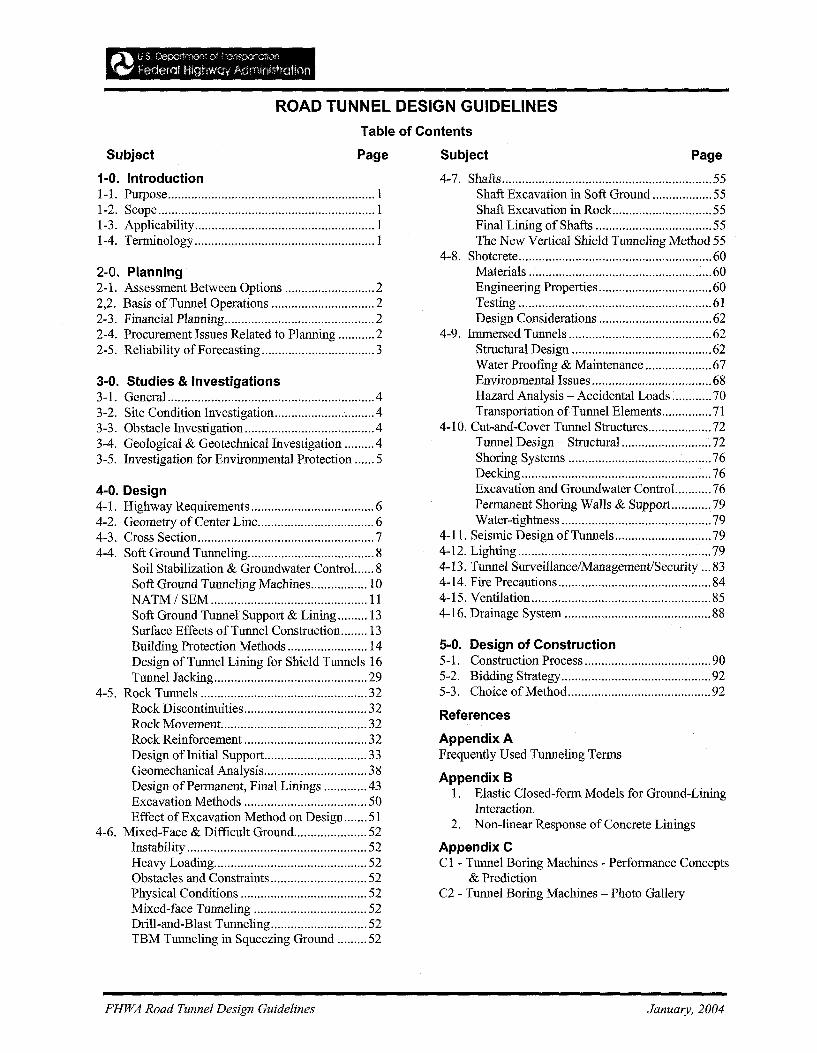
ROAD TUNNEL DESIGN GUIDELINES
Table of Contents
SUbject Page
1-0. Introduction1-1. Purpose 11-2. Scope 11-3. Applicability 11-4. Terminology l
2-0. Planning2-1. Assessment Between Options 22,2. Basis ofTunnel Operations 22-3. Financial Planning 22-4. Procurement Issues Related to Planning 22-5. Reliability of Forecasting 3
3-0. Studies & Investigations3-1. General 43-2. Site Condition Investigation 43-3. Obstacle Investigation 43-4. Geological & Geotechnical Investigation .43-5. Investigation for Environmental Protection 5
4-0. Design4-1. Highway Requirements 64-2. Geometry of Center Line 64-3. Cross Section 74-4. Soft Ground Tunneling 8
Soil Stabilization & Groundwater Control... 8Soft Ground Tunneling Machines 10NATM/ SEM 11Soft Ground Tunnel Support & Lining 13Surface Effects ofTunnel Construction 13Building Protection Methods 14Design ofTunnel Lining for Shield Tunnels 16Tunnel Jacking 29
4-5. Rock Tunnels 32Rock Discontinuities 32Rock Movement. 32Rock Reinforcement 32Design ofInitial Support 33Geomechanical Analysis 38Design ofPermanent, Final Linings 43Excavation Methods 50Effect of Excavation Method on Design 51
4-6. Mixed-Face & Difficult Ground 52Instability 52Heavy Loading 52Obstacles and Constraints 52Physical Conditions 52Mixed-face Tunneling 52Drill-and-Blast Tunneling 52TBM Tunneling in Squeezing Ground 52
FHWA Road Tunnel Design Guidelines
Subject Page
4-7. Shafts 55Shaft Excavation in Soft Ground 55Shaft Excavation in Rock 55Final Lining of Shafts 55The New Vertical Shield Tunneling Method 55
4-8. Shotcrete 60Materials 60Engineering Properties 60Testing 61Design Considerations 62
4-9. Immersed Tunnels 62Structural Design 62Water Proofing & Maintenance 67Environmental Issues 68Hazard Analysis - Accidental Loads 70Transportation ofTunnel Elements 71
4-10. Cut-and-Cover Tunnel Structures 72Tunnel Design - Structural 72Shoring Systems 76Decking 76Excavation and Groundwater Contro!.. 76Permanent Shoring Walls & Support 79Water-tightness 79
4-11. Seismic Design ofTunnels 794-12. Lighting 794-13. Tunnel SurveillancelManagement/Security 834-14. Fire Precautions 844-15. Ventilation 854-16. Drainage System 88
5-0. Design of Construction5-1. Construction Process 905-2. Bidding Strategy 925-3. Choice of Method 92
References
Appendix AFrequently Used Tunneling Terms
Appendix B1. Elastic Closed-form Models for Ground-Lining
Interaction.2. Non-linear Response of Concrete Linings
Appendix CCl - Tunnel Boring Machines - Performance Concepts
& PredictionC2 - Tunnel Boring Machines - Photo Gallery
January, 2004
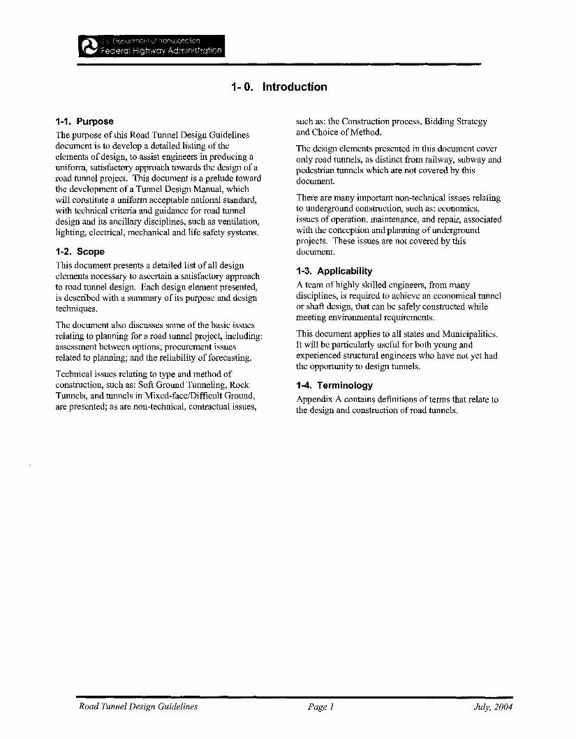
1- O. Introduction
1-1. PurposeThe purpose of this Road Tunnel Design Guidelinesdocument is to develop a detailed listing of theelements of design, to assist engineers in producing auniform, satisfactory approach towards the design of aroad tunnel project. This document is a prelude towardthe development of a Tunnel Design Manual, whichwill constitute a uniform acceptable national standard,with technical criteria and guidance for road tunneldesign and its ancillary disciplines, such as ventilation,lighting, electrical, mechanical and life safety systems.
1-2. ScopeThis document presents a detailed list of all designelements necessary to ascertain a satisfactory approachto road tunnel design. Each design element presented,is described with a summary of its purpose and designtechniques.
The document also discusses some of the basic issuesrelating to planning for a road tunnel project, including:assessment between options; procurement issuesrelated to planning; and the reliability of forecasting.
Technical issues relating to type and method ofconstruction, such as: Soft Ground Tunneling, RockTunnels, and tunnels in Mixed-face/Difficult Ground,are presented; as are non-technical, contractual issues,
such as: the Construction process, Bidding Strategyand Choice of Method.
The design elements presented in this document coveronly road tunnels, as distinct from railway, subway andpedestrian tunnels which are not covered by thisdocument.
There are many important non-technical issues relatingto underground construction, such as: economics,issues of operation, maintenance, and repair, associatedwith the conception and planning ofundergroundprojects. These issues are not covered by thisdocument.
1-3. ApplicabilityA team of highly skilled engineers, from manydisciplines, is required to achieve an economical tunnelor shaft design, that can be safely constructed whilemeeting environmental requirements.
This document applies to all states and Municipalities.It will be particularly useful for both young andexperienced structural engineers who have not yet hadthe opportunity to design tunnels.
1-4. TerminologyAppendix A contains definitions of terms that relate tothe design and construction of road tunnels.
Road Tunnel Design Guidelines Page 1 July, 2004
...... IJ $ [;'CCQrtlT~)f,~ cJ rr<lf\SD{)1o:t~)nr.., federal Higrlway AdministraTIon
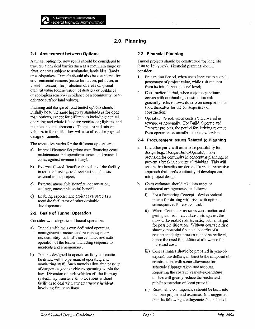
2.0. Planning
2-1. Assessment between Options
A tunnel option for new roads should be considered totraverse a physical barrier such as a mountain range orriver, or areas subject to avalanche, landslides, floodsor earthquakes. Tunnels should also be considered forenvironmental reasons (noise limitation, pollution, orvisual intrusion); for protection of areas of specialcultural value (conservation of districts or buildings);or ecological reasons (avoidance of a community, or toenhance surface land values).
Planning and design of road tunnel options shouldinitially be to the same highway standards as for openroad options, except for differences including: capital,operating and whole life costs; ventilation; lighting andmaintenance requirements. The nature and mix ofvehicles in the traffic flow will also affect the physicaldesign of tunnels.
The respective merits for the different options are:
a) Internal Finance: Set prime cost, financing costs,maintenance and operational costs, and renewalcosts, against revenue (if any);
b) External Costed Benefits: the value of the facilityin terms of savings to direct and social costsexternal to the project;
c) External uncostable Benefits: conservation,ecology, uncostable social benefits;
d) Enabling aspects: The project evaluated as arequisite facilitator ofother desirabledevelopments.
2-2. Basis of Tunnel Operation
Consider two categories of tunnel operation:
a) Tunnels with their own dedicated operatingmanagement structure and resources; retainresponsibility for traffic surveillance and safeoperation of the tunnel, including response toincidents and emergencies;
b) Tunnels designed to operate as fully automaticfacilities, with no permanent operating andmonitoring staff. Such tunnels allow free passageof dangerous goods vehicles operating within thelaw. Diversion of such vehicles off the freewaysystem may transfer risk to locations withoutfacilities to deal with any emergency incidentinvolving fire or spillage.
2-3. Financial Planning
Tunnel projects should be constructed for long life(100 to 150 years). Financial planning shouldconsider:
1. Preparation Period, when costs increase to a smallpercentage ofproject value, while risk reducesfrom its initial 'speculative' level;
2. Construction Period, when major expenditureoccurs with outstanding construction riskgradually reduced towards zero on completion, orsoon thereafter for the consequences ofconstruction;
3. Operation Period, when costs are recovered inrevenue or notionally. For Build, Operate andTransfer projects, the period for deriving revenuefrom operation on transfer to state ownership.
2-4. Procurement Issues Related to Planning
a. If another party will assume responsibility fordesign (e.g., Design-Build-Operate), makeprovision for continuity in conceptual planning, toprevent a break in conceptual thinking. This willensure that benefits are derived from an innovativeapproach that needs continuity of developmentinto project design.
b. Costs estimates should take into accountcontractual arrangements, as follows:
i) For a Partnering Concept - devise optimalmeans for dealing with risk, with optimalconsequences for cost control;
ii) Where Contractor assumes construction andgeological risk - calculate costs against themost unfavorable risk scenario, with a marginfor possible litigation. Without equitable risksharing, potential financial benefits of acompetent design process cannot be realized,hence the need for additional allowance forincreased cost.
iii) Cost estimates should be prepared in year-ofexpenditure dollars, inflated to the midpoint ofconstruction, with some allowance forschedule slippage taken into account.Reporting the costs in year-of-expendituredollars will greatly reduce the media andpublic perception of "cost growth".
iv) Reasonable contingencies should be built intothe total project cost estimate. It is suggestedthat the following contingencies be included:
Road Tunnel Design Guidelines Page 2 July, 2004
./ A construction contingency for cost growthduring construction;
./ A design contingency based on differentlevels of design completion;
./ An overall Management contingency forthird-party and other unanticipated changes;and
./ Other contingencies for areas that may showa high potential for risk and change; forexample: environmental mitigation, utilities,highly specialized designs, etc.
v) Cost estimates should consider the economicimpact of the major project on the localgeographical area; for example, materialmanufacturers that would normally competewith one another may be "forced" to teamtogether in order to meet the demand of themajor project. Extremely large constructionpackages also have the potential to reduce theamount of contractors that have the capabilityofbidding on the project, and may need to bebroken up into smaller contracts to attractadditional competition. Bid options(simultaneous procurements of similar scopeswith options to award) should also beconsidered for potential cost savings resulting
from economies of scale and reducedmobilization. A Value Analysis should beperformed on the project to determine themost economical and advantageous way ofpackaging the contracts for advertisement.
2-5. Reliability of Forecasting
For subsurface projects, the site-specific nature of theground further compounds the uncertainties offinancial forecasting. The main areas ofuncertainty,listed below, should be qualified in estimates:
• Politics;
• Competence and agenda of source ofestimates;
• Timing of completion;
• Development of competitor projects /technology;
• Ranges and qualifications
• Attention to climate of risk;
• Potential changes in requirements;
• Contractual relationships;
• Bidding process
Road Tunnel Design Guidelines Page 3 July, 2004
....... Ij ~ Depcrtn-'Gff ,y: IrJI"X;<'t(ltHxll..- Federar HilghwO'y Admimstrahof1
3.0. Studies & Investigations
3-1. GeneralInvestigations should be conducted to obtain data forplanning, design, construction and maintenance.
3-2. Site Condition InvestigationSite condition investigation should be conducted toselect tunnel route, judge suitability of tunnel methods,size of the tunnel, and should cover local conditionsalong the tunnel alignment related to:
a. Land usage and related property rights, includingencumbrances and restrictions onsurface/underground land usage
b. Future development plans along the route, includingtheir scale and schedules;
c. Road classification and traffic conditions; to aid indetermining vertical shaft locations;
d. Difficulty ofland use for construction; e.g.,construction yard around a vertical shaft;
e. River, lake and sea conditions; including crosssection, structure of its banks, etc.
f. Availability and capacity ofpower, water andsewage connection for construction.
3-3. Obstacle Investigation
Obstacle investigation should be conducted to identifythe following items:
a. Existing surface and underground structures;including foundation type, basements and structureswith sensitive instruments;
b. Existing underground utilities;
c. Wells in use and abandoned wells to assess risk ofblowout/leakage of slurry, oxygen-deficient air.
d. Sites of removed structures and temporary works,including contaminated soils and groundwater.
3-4. Geological & Geotechnical Investigations
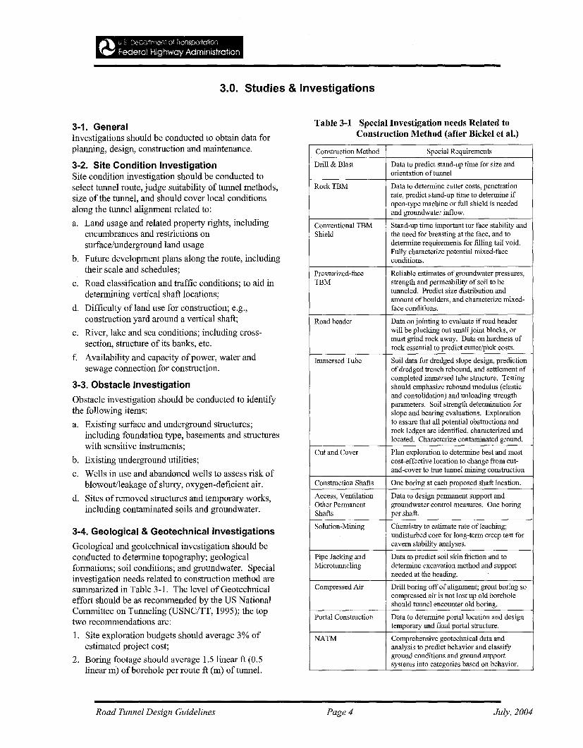
Geological and geotechnical investigation should beconducted to determine topography; geologicalformations; soil conditions; and groundwater. Specialinvestigation needs related to construction method aresummarized in Table 3-1. The level ofGeotechnicaleffort should be as recommended by the US NationalCommittee on Tunneling (USNC/TT, 1995); the toptwo recommendations are:
1. Site exploration budgets should average 3% ofestimated project cost;
2. Boring footage should average 1.5 linear ft (0.5linear m) of borehole per route ft (m) of tunnel.
Table 3-1 Special Investigation needs Related toConstruction Method (after Bickel et aI.)
Construction Method Special Requirements
Drill & Blast Data to predict stand-up time for size andorientation of tunnel
RockTBM Data to determine cutter costs, penetrationrate, predict stand-up time to determine ifopen-type machine or full shield is neededand groundwater inflow.
Conventional TBM Stand-up time important tor face stability andShield the need for breasting at the face, and to
determine requirements for filling tail void.Fully characterize potential mixed-faceconditions.
Pressurized-face Reliable estimates of groundwater pressures,TBM strength and permeability of soil to be
tunneled. Predict size distribution andamount of boulders, and characterize mixed-face conditions.
Road header Data on jointing to evaluate if road headerwill be plucking out small joint blocks, ormust grind rock away. Data on hardness ofrock essential to predict cutter/pick costs.
Immersed Tube Soil data for dredged slope design, predictionof dredged trench rebound, and settlement ofcompleted immersed tube structure. Testingshould emphasize rebound modulus (elasticand consolidation) and unloading strengthparameters. Soil strength determination forslope and bearing evaluations. Explorationto assure that all potential obstructions androck ledges are identified, characterized andlocated. Characterize contaminated ground,
Cut and Cover Plan exploration to determine best and mostcost-effective location to change from cut-and-cover to true tuunel mining construction
Construction Shafts One boring at each proposed shaft location.
Access, Ventilation Data to design permanent support andOther Permanent groundwater control measures. One boringShafts per shaft.
Solution-Mining Chemistry to estimate rate ofleaching;undisturbed core for long-term creep test forcavern stability analyses.
Pipe Jacking and Data to predict soil skin friction and toMicrotunneling determine excavation method and support
needed at the heading.
Compressed Air Drill boring offof alignment; grout boring socompressed air is not lost up old boreholeshould tunnel encounter old boring.
Portal Construction Data to determine portal location and designtemporary and final portal structure.
NATM Comprehensive geotechnical data andanalysis to predict behavior and classifyground conditions and ground supportsystems into categories based on behavior.
Road Tunnel Design Guidelines Page 4 July, 2004
3-5. Investigation for Environmental Protection
The following items should be investigated, as the needarises, in order to protect the environment, during andafter tunnel construction:
a. Noise and Vibration
Should be monitored both prior to and duringconstruction to evaluate those generated just bytunnel construction
b. Ground Movements
Condition of the ground and structures along thealignment should be surveyed and monitored,during and after construction, in order to quantifydegree ofground heave I subsidence and effect onstructures along tunnel route.
c. Groundwater
Use of wells, water level and quality ofthe wells,and spring water in the sphere of influence shouldbe surveyed. Timing of survey and theconstruction should be compared to account forseasonal fluctuation in groundwater level.
d. Oxygen-deficient Air and Hazardous Gases
Such as methane; oxygen-deficient air resultingfrom oxidation of iron content and organicmaterial in soil may be pushed into nearby wellsand basements by application of the pneumaticshield tunneling method.
Therefore, locations of wells, their water levelsand basement structures to be potentially affectedshould be investigated prior to construction andthe leakage of oxygen-deficient air should bemonitored during construction. Existence ofhazardous gases, such as methane should beinvestigated prior to construction by borings. Ifdetected, its concentration should be measured andmonitored prior to, and during, construction.
e. Chemical grouting
Water quality in wells and rivers that will bepotentially affected by leakage of injectedchemical grout or slurry from shield tunnelingshould be surveyed and monitored for any changesduring construction
f. Construction By-products
Reduction and recycling of construction byproducts should be encouraged for smoothconstruction operations and preservation of theenvironment.
Road Tunnel Design Guidelines Page 5 July, 2004

4.0. Design
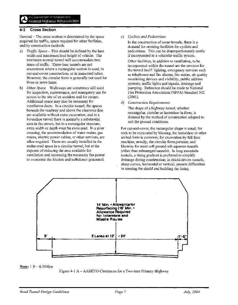
4-1. Highway RequirementsHighway requirements for road tunnels vary accordingto the tunnel situation and character (urban, interstate,sub aqueous or mountain), and whether long or short.Standards for lane and shoulder width, and verticalclearance for highways, should be as established by theFHWA and AASHTO according to classification(Figure 4-IA).
a. General -- In addition to width of traveled lanes, leftand right shoulders should be provided flush withpavement surface.
Horizontal clearances on curved tunnels should beincreased to provide sight distances past the tunnelwall.
In lieu of maintenance walks, closed circuittelevision camera surveillance is used, and lanes areclosed when maintenance access is required.
b. Urban Underpasses - the straightest practicable lineshould be adopted and gradients should be restricted,ifpossible, to less than 3-4%, because steepergradients give rise to congestion when large, heavilyloaded vehicles are ascending;
c. Interstate Highway Tunnels - Tunnel line andgradients should conform to standards specified forthe interstate: sight lines appropriate to the designspeed should require particular care, especiallywhere vertical curves are necessary. Design speedshould be greater than 60 mph (97 kmph), unlessotherwise restricted in urban areas; the minimumradius of curvature should not be less than 1,500 ft(457 m).
d. Sub aqueous Tunnels - line should be fixed nearly atright angles to the waterway, to minimize tunnellength, unless valley topography imposes anotheralignment. As with urban tunnels, any gradientexceeding 3-4% slows heavy trafficdisproportionately. Tunnel profile will usuallycomprise a descending gradient, a nearly levelcentral gradient and a rising gradient. Verticalcurves required at changes ofgradient should be aslong as practicable, to simplifY construction if ashield is used, and to avoid restricting the line ofsight in the tunnel approaching the change ofgradient.
e. Mountain Tunnels - The geometry should be relatedto the topography and geology in order to design andensure the stability of cuttings, embankments,viaducts and portals leading to tunnels.
4-2. Geometry of Center LineThe principal factors determining the center lineinclude: the relative positions of the portals anddirections of approach; geology; clearances fromexternal obstacles; gradients; vertical curves; andhorizontal curves.
a) Approaches - For very short and simple tunnels,align the tunnel in a straight line joining the portals,otherwise introduce curves to suit the approaches,and varying gradients to carry it under and aroundobstacles.
b) Geology - The choice of the most suitable strata fortunneling will influence the alignment, as may theavoidance of water-bearing ground or unstable rock.
c) Clearance from External Obstacles -- As a broadgeneralization, it is usually satisfactory if uniformundisturbed ground outside the tunnel extends forone tunnel diameter; more careful analysis isrequired if discontinuities and obstructions occurwithin this zone.
d) Gradients - A steep gradient should not be used forhighway tunnels because heavy vehicles resort touse of their lowest gears, reducing traffic capacityand increasing demand on the ventilation system.Gradients should be limited to 3-4%. A minimumgradient should be specified (0.25%, usually) toensure longitudinal drainage of the roadway.
e) Vertical Curves - Changes ofgradient are normallysmall in interstate highway tunnels and mountaintunnels, and connecting curves are correspondinglyshort, and should follow applicable roadwaygeometry specifications..
f) Horizontal Curves - In plan, curves may benecessary to align the tunnel with its approachroads and to avoid obstacles in the ground. Thesame considerations apply in determining the radiusas in surface roads: design speed, centrifugal force,super elevation, and line of sight.
On very sharp curves, some extra lane width forlong vehicles is desirable, but may be prohibitivelyexpensive.
Road Tunnel Design Guidelines Page 6 July, 2004
4-3 Cross Section
General- The cross section is determined by the spacerequired for traffic, space required for other facilities,and by construction methods.
a) Traffic Space - This should be defmed by the lanewidth and maximum load height of vehicle. Theminimum normal tunnel will accommodate twolanes of traffic. Three-lane tunnels are notuncommon where a rectangular section is used, incut-and-cover construction, or in immersed tubes.However, the circular form is generally not used forthree or more lanes.
b) Other Space - Walkways are sometimes still usedfor inspection, maintenance, and emergency use foraccess to the site of an accident and for escape.Additional space may also be necessary forventilation ducts. In a circular tunnel, the spacesbeneath the roadway and above the clearance lineare available without extra excavation, and in ahorseshoe tunnel there is normally a substantialarea in the crown; but in a rectangular structure,extra width or depth must be excavated. In a rivercrossing, the accommodation of water mains, gasmains, electric power cables, or other services, areoften required. These are usually installed in theunder-road space in a circular tunnel, but at theexpense of reducing the area available forventilation and increasing the necessary fan powerto overcome the friction and turbulence generated.
c) Cyclists and Pedestrians
In the construction of some tunnels, there is ademand for crossing facilities for cyclists andpedestrians. This can be disproportionately costlyif incorporated in a vehicular traffic system.
Other facilities, in addition to ventilation, to beincorporated within the tunnel are the services forthe tunnel itself: lighting, emergency services suchas telephones and fire alarms, fire mains, air qualitymonitoring devices and visibility, public addresssystems, traffic lights and signals, drainage andpumping. Reference should be made to NationalFire Protection Association (NFPA) Standard 502(2001).
d) Construction Requirements
The shape of a highway tunnel, whetherrectangular, circular or horseshoe in form, isdictated by the method of construction adopted tosuit the ground conditions.
For cut-and-cover, the rectangular shape is usual; forrock to be excavated by blasting, the horseshoe or otherarched form is common; for excavation by full facemachine, usually, the circular form pertains; andlikewise for most soft ground sub aqueous tunnels(other than submerged tunnels). In long mountaintunnels, a rising gradient is preferred to simplifydrainage during construction; in shield-driven tunnels,sharp curves, horizontal or vertical, present difficultiesin steering the shield and building the lining.
3'
Note: 1 ft = 0.3048m
14' Min. ,.. AUowancefofAeIUrladn~6'Min. +Allowance. ..• uitedfor lntvltate andMillil. Rou*
2 lanes at 12' :t 24'
Figure 4-1 A - AASHTO Clearances for a Two-lane Primary Highway
Road Tunnel Design Guidelines Page 7 July, 2004
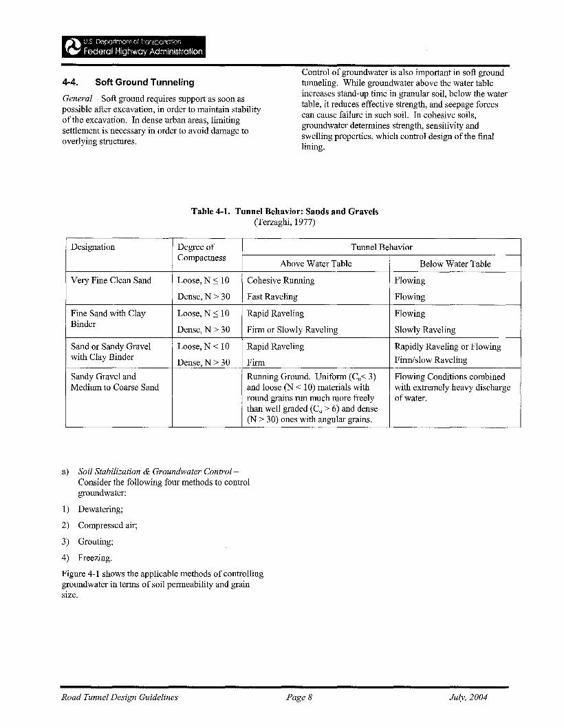
4-4. Soft Ground Tunneling
General - Soft ground requires support as soon aspossible after excavation, in order to maintain stabilityof the excavation. In dense urban areas, limitingsettlement is necessary in order to avoid damage tooverlying structures.
Control of groundwater is also important in soft groundtunneling. While groundwater above the water tableincreases stand-up time in granular soil, below the watertable, it reduces effective strength, and seepage forcescan cause failure in such soil. In cohesive soils,groundwater determines strength, sensitivity andswelling properties, which control design of the fmallining.
Table 4-1. Tunnel Behavior: Sands and Gravels(Terzaghi, 1977)
Designation Degree of Tunnel BehaviorCompactness
Above Water Table Below Water Table
Very Fine Clean Sand Loose, N::; 10 Cohesive Running Flowing
Dense, N> 30 Fast Raveling Flowing
Fine Sand with Clay Loose, N::; 10 Rapid Raveling FlowingBinder
Dense, N> 30 Firm or Slowly Raveling Slowly Raveling
Sand or Sandy Gravel Loose, N < 10 Rapid Raveling Rapidly Raveling or Flowingwith Clay Binder
Dense, N> 30 Firm Finn/slow Raveling
Sandy Gravel and Running Ground. Uniform (Cu< 3) Flowing Conditions combinedMedium to Coarse Sand and loose (N < 10) materials with with extremely heavy discharge
round grains run much more freely of water.than well graded (Cu > 6) and dense(N > 30) ones with angular grains.
a) Soil Stabilization & Groundwater ControlConsider the following four methods to controlgroundwater:
I) Dewatering;
2) Compressed air;
3) Grouting;
4) Freezing.
Figure 4-1 shows the applicable methods of controllinggroundwater in terms of soil permeability and grainsize.
Road Tunnel Design Guidelines Page 8 July, 2004
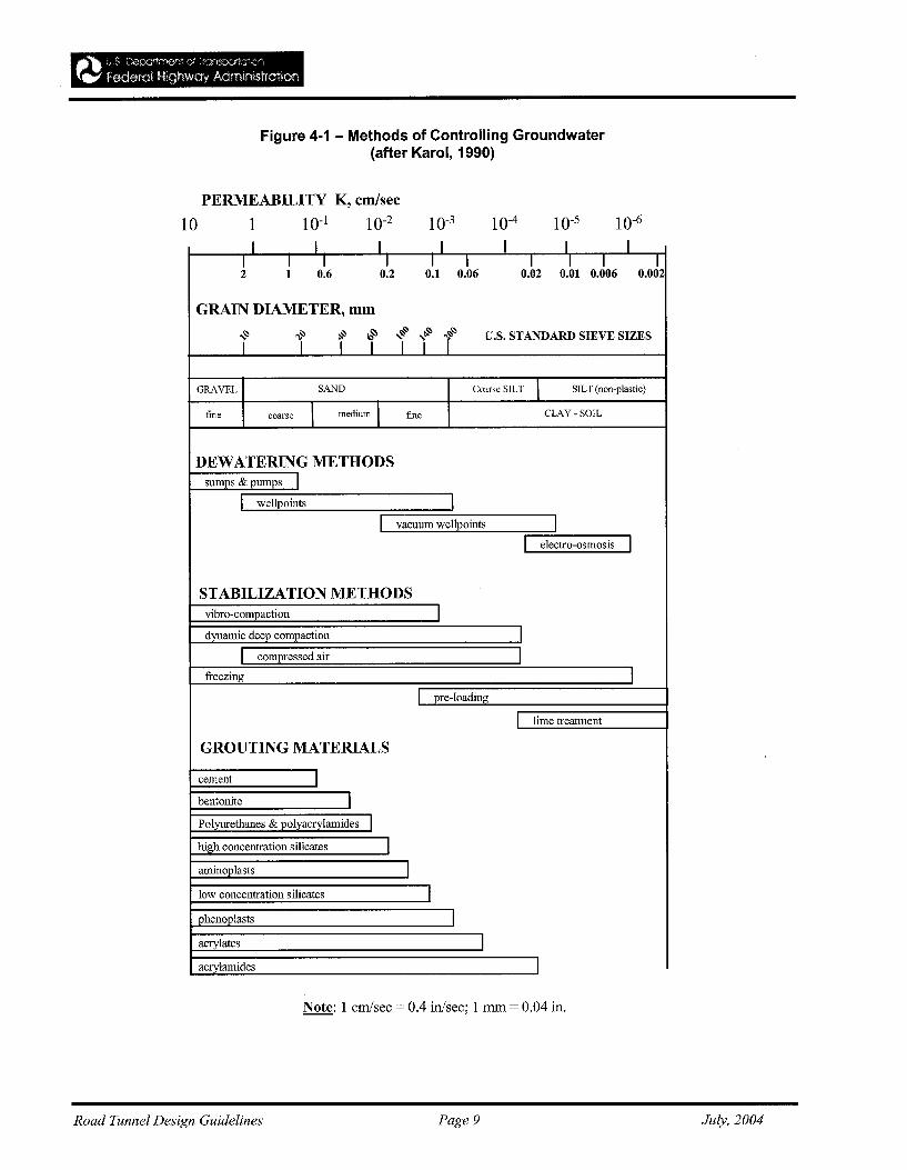
Figure 4-1 - Methods of Controlling Groundwater(after Karol, 1990)
PERMEABILITY K, em/sec
10 1 10-1 10-2 10-3 10-4 10-5 10-6
I I I I I I I
! I I I I I I I I I1 0.6 0.2 0.1 0.06 0.02 0.01 0.006 0.002
GRAIN DIAMETER, mm
>$' -.~ ~ ia~ ~~ ~ r~ u.s. STANDARD SIEVE SIZESf I T 1 I 1
GRAVEL SAND Coarse SILT I SILT (non-plastic)
fine coarse I medium I fine CLAY -SOIL
DEWATERING METHODSsumps & pumps I
I wellpoints II vacuum wellpoints I
I electro-osmosis I
STABILIZATION METHODSvibro-compaction
dynamic deep compaction II compressed air I
freezing II pre-loading
I lime treatment
GROUTING MATERIALS
cement Ibentonite IPolyurethanes & polyacrylamides Ihigh concentration silicates Iaminoplasts I
low concentration silicates I
phenoplasts
acrylates Iacrylamides I
Note: 1 em/sec = 0.4 in/sec; 1 mm = 0.04 in.
Road Tunnel Design Guidelines Page 9 July, 2004
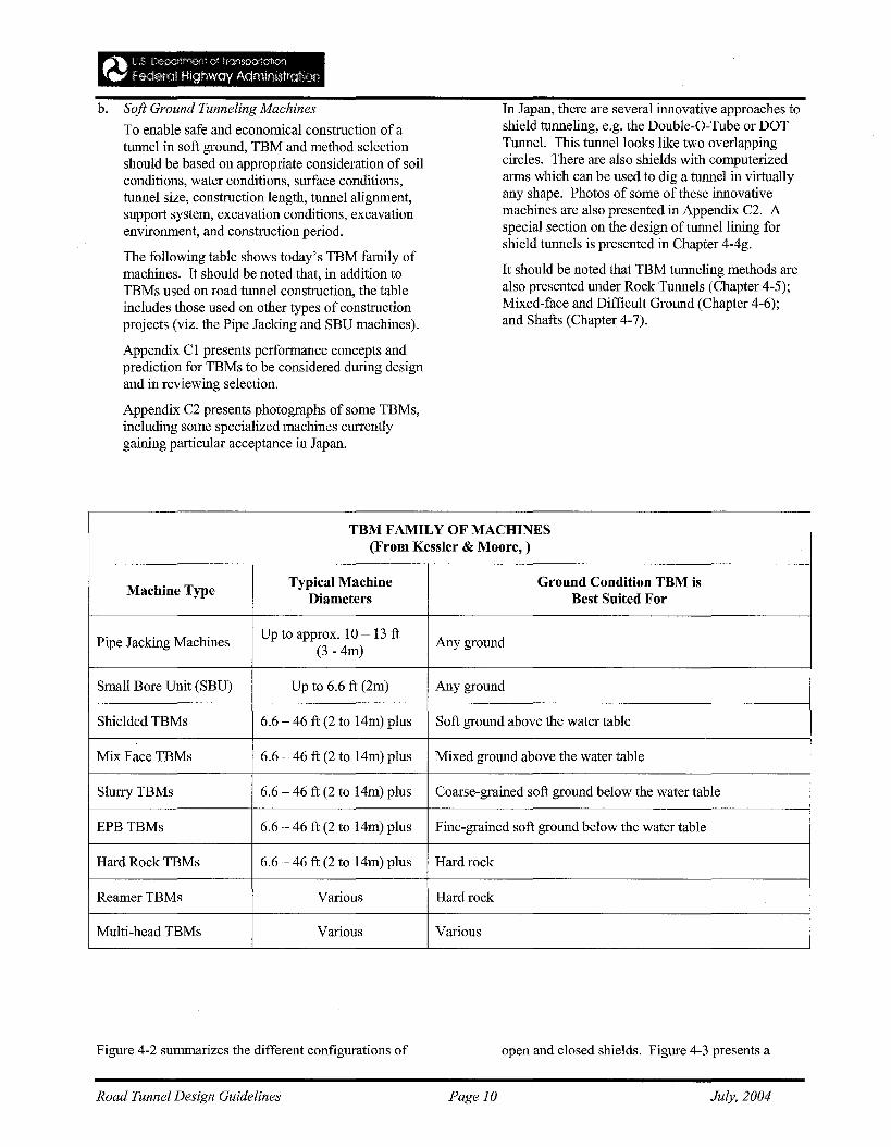
b. Soft Ground Tunneling Machines
To enable safe and economical construction of atunnel in soft ground, TBM and method selectionshould be based on appropriate consideration of soilconditions, water conditions, surface conditions,tunnel size, construction length, tunnel alignment,support system, excavation conditions, excavationenvironment, and construction period.
The following table shows today's TBM family ofmachines. It should be noted that, in addition toTBMs used on road tunnel construction, the tableincludes those used on other types of constructionprojects (viz. the Pipe Jacking and SBU machines).
Appendix CI presents performance concepts andprediction for TBMs to be considered during designand in reviewing selection.
Appendix C2 presents photographs of some TBMs,including some specialized machines currentlygaining particular acceptance in Japan.
In Japan, there are several innovative approaches toshield tunneling, e.g. the Double-O-Tube or DOTTunnel. This tunnel looks like two overlappingcircles. There are also shields with computerizedarms which can be used to dig a tunnel in virtuallyany shape. Photos of some of these innovativemachines are also presented in Appendix C2. Aspecial section on the design of tunnel lining forshield tunnels is presented in Chapter 4-4g.
It should be noted that TBM tunneling methods arealso presented under Rock Tunnels (Chapter 4-5);Mixed-face and Difficult Ground (Chapter 4-6);and Shafts (Chapter 4-7).
TBM FAMILY OF MACHINES(From Kessler & Moore, )
Machine TypeTypical Machine Gronnd Condition TBM is
Diameters Best Snited For
Pipe Jacking MachinesUp to approx. 10 - 13 ft
Any ground(3 - 4m)
Small Bore Unit (SBU) Up to 6.6 ft (2m) Any ground
Shielded TBMs 6.6 - 46 ft (2 to 14m) plus Soft ground above the water table
Mix Face TBMs 6.6 - 46 ft (2 to 14m) plus Mixed ground above the water table
SlurryTBMs 6.6 - 46 ft (2 to 14m) plus Coarse-grained soft ground below the water table
EPBTBMs 6.6 - 46 ft (2 to 14m) plus Fine-grained soft ground below the water table
Hard Rock TBMs 6.6 - 46 ft (2 to 14m) plus Hard rock
ReamerTBMs Various Hard rock
Multi-head TBMs Various Various
Figure 4-2 summarizes the different configurations of
Road Tunnel Design Guidelines Page 10
open and closed shields. Figure 4-3 presents a
July, 2004
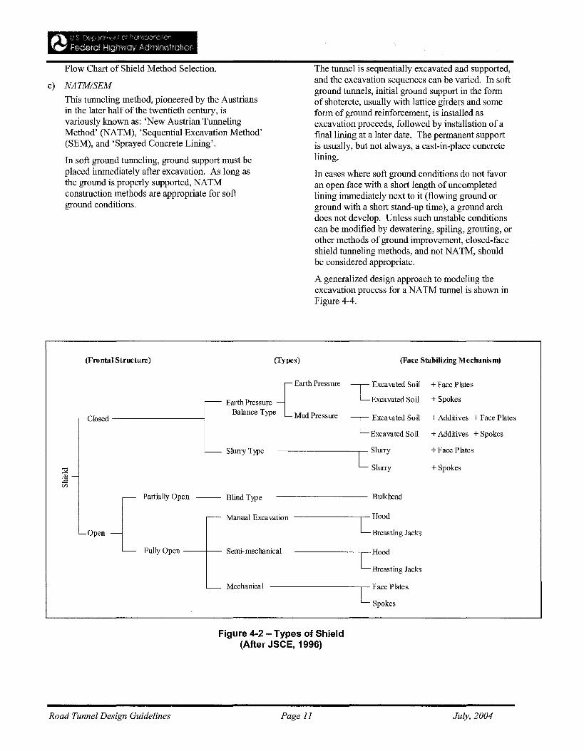
Flow Chart of Shield Method Selection.
c) NATM/SEM
This tunneling method, pioneered by the Austriansin the later half of the twentieth century, isvariously known as: 'New Austrian TunnelingMethod' (NATM), 'Sequential Excavation Method'(SEM), and 'Sprayed Concrete Lining'.
In soft ground tunneling, ground support must beplaced immediately after excavation. As long asthe ground is properly supported, NATMconstruction methods are appropriate for softground conditions.
The tunnel is sequentially excavated and supported,and the excavation sequences can be varied. In softground tunnels, initial ground support in the formof shotcrete, usually with lattice girders and someform of ground reinforcement, is installed asexcavation proceeds, followed by installation of afinal lining at a later date. The permanent supportis usually, but not always, a cast-in-place concretelining.
In cases where soft ground conditions do not favoran open face with a short length of uncompletedlining immediately next to it (flowing ground orground with a short stand-up time), a ground archdoes not develop. Unless such unstable conditionscan be modified by dewatering, spiling, grouting, orother methods of ground improvement, closed-faceshield tunneling methods, and not NATM, shouldbe considered appropriate.
A generalized design approach to modeling theexcavation process for a NATM tunnel is shown inFigure 4-4.
(Frontal Structure) (Types) (Face Stabilizing Mechanism)
~ Excavated Soil
LExcavated Soil
L Excavated Soil
Excavated Soil[
Earth Pressure {EarthPressure
Balance Type Mud Pressurer-Closed ---------
Slurry Type --------[ Slurry
Slurry
+ Face Plates
+ Spokes
+ Additives + Face Plates
+ Additives + Spokes
+ Face Plates
+ Spokes
[HOOd
Breasting Jacks
--------- Bulkhead
..- Manual Excavation ------[Hood
Breasting Jacks
-- Blind TypeI ',",.lly O,on
L FIDlyO,~ --t-- Semi-mechanical
'-Open
'--- Mechanical [ Face Plates
Spokes
Figure 4-2 - Types of Shield(After JSCE, 1996)
Road Tunnel Design Guidelines Page 11 July, 2004
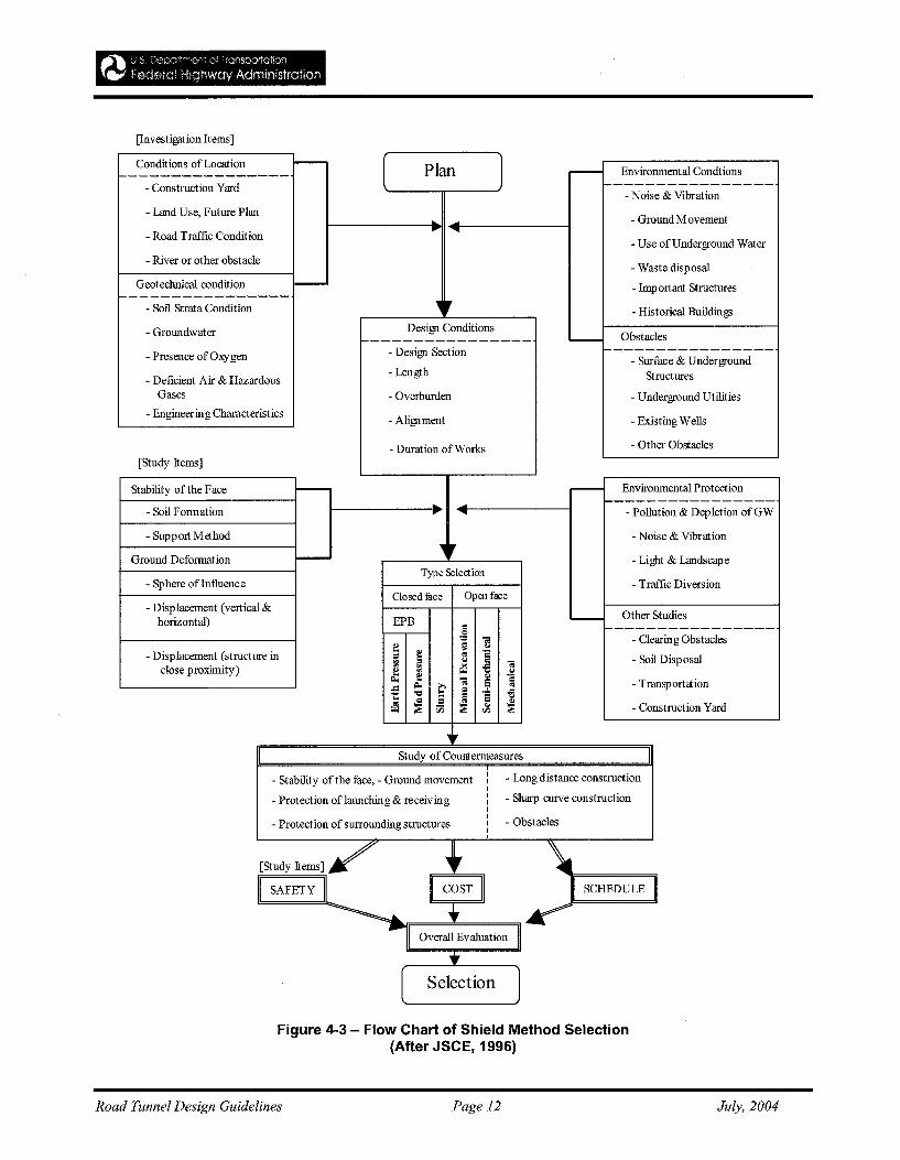
[Investigation Items]
Conditions of Location ----------------- Plan ,....- Environmental Condtions
- Construction Yard ----------------- Noise & Vibration
- Land Use, Future Plan- Ground Movement
- Road Traffic Condition... ...
- Use of Underground Water
- River or other obstacle- Waste disposal
Geotechnical condition - - Imp ortant Structures---------------- ., r- Soil Strata Condition - Historical BuildingsDesign Conditions- Groundwater Obstacles
~--------------- ""---
- Presence of Oxygen - Design Section ----------------- Surface & Underground
- Deficient Air & Hazardous- Length Structures
Gases - Overburden - Underground Utilities
- Engineering Characteristics- Alignment - Existing Wells
- Duration ofWorks - Other Obstacles
[Study Items]
Stability ofthe Face
]- Environmental Protection
~ ... ~---------------- Soil Formation - Pollution & Depletion of GW
- Support Method - Noise & Vibration., rGround Deformation - Light & Landscape
Type Selection- Sphere ofInfluence - Traffic Diversion
Closed fuce Open face- Displacement (vertical &
Other Studieshorizontal) EPB -
§ ~---------------
"" B - Clearing Obstacles~ ~
- Displacement (structure in~
~ " "§ - Soil Disposal~
...'01close proximity) £ ~ '5.~~ "'01 ~ - Transp ortation..= ~ .... :=
t: 'tl l:~
"s '5~ ~ ~ " ~ - Construction Yard00
"Study of Countermeasures
- Stability of the face, - Ground movementI - Long distance constructionII
- Protection oflaunching & receiving I - Sharp curve constructionIII
- Obstacles- Protection of surrounding structures III
[Study Items]/' • \SAFETY II COST II SCHEDULE
..-II Overall Evaluation I...[ Selection
Figure 4-3 - Flow Chart of Shield Method Selection(After JSCE, 1996)
Road Tunnel Design Guidelines Page 12 July, 2004
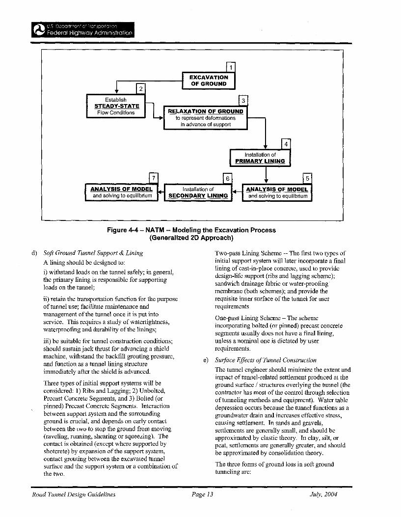
EstablishSTEADY-STATE
Flow Conditions
EXCAVATIONOF GROUND
3
RELAXATION OF GROUNDto represent deformations
in advance of support
4
ANALYSIS OF MODELand solving to equilibrium
Installation ofSECONDARY LINING
Installation ofPRIMARY LINING
5
ANALYSIS OF MODELand solving to equilibrium
Figure 4-4 - NATM -- Modeling the Excavation Process(Generalized 20 Approach)
d) Soft Ground Tunnel Support & Lining
A lining should be designed to:
i) withstand loads on the tunnel safely; in general,the primary lining is responsible for supportingloads on the tunnel;
ii) retain the transportation function for the purposeof tunnel use; facilitate maintenance andmanagement of the tunnel once it is put intoservice. This requires a study of watertightness,waterproofing and durability of the linings;
iii) be suitable for tunnel construction conditions;should sustain jack thrust for advancing a shieldmachine, withstand the backfill grouting pressure,and function as a tunnel lining structureimmediately after the shield is advanced.
Three types of initial support systems will beconsidered: 1) Ribs and Lagging; 2) Unbolted,Precast Concrete Segments, and 3) Bolted (orpinned) Precast Concrete Segments. Interactionbetween support system and the surroundingground is crucial, and depends on early contactbetween the two to stop the ground from moving(raveling, running, shearing or squeezing). Thecontact is obtained (except where supported byshotcrete) by expansion of the support system,contact grouting between the excavated tunnelsurface and the support system or a combination ofthe two.
Two-pass Lining Scheme -- The first two types ofinitial support system will later incorporate a finallining of cast-in-place concrete, used to providedesign-life support (ribs and lagging scheme);sandwich drainage fabric or water-proofing·membrane (both schemes); and provide therequisite inner surface of the tunnel for userrequirements
One-pass Lining Scheme - The schemeincorporating bolted (or pinned) precast concretesegments usually does not have a fmallining,unless a nominal one is dictated by userrequirements.
e) Surface Effects ofTunnel Construction
The tunnel engineer should minimize the extent andimpact of tunnel-related settlement produced at theground surface / structures overlying the tunnel (thecontractor has most of the control through selectionof tunneling methods and equipment). Water tabledepression occurs because the tunnel functions as agroundwater drain and increases effective stress,causing settlement. In sands and gravels,settlements are generally small, and should beapproximated by elastic theory. In clay, silt, orpeat, settlements are generally greater, and shouldbe approximated by consolidation theory.
The three forms of ground loss in soft groundtunneling are:
Road Tunnel Design Guidelines Page 13 July, 2004
~ Face Losses - soil movement out in front ofthe shield and into the shield, through raveling,caving, flowing, running, or squeezing;
~ Shield Losses - soil movement toward theshield between the cutting edge and tail, as aresult of the shield plowing, pitching, oryawing, and from the void created byovercutters;
~ Tail Losses - soil movement toward thesupport system as it leaves the shield's tail,resulting from soil moving to fill the tail voidcreated by the volume of the tail skin plate and
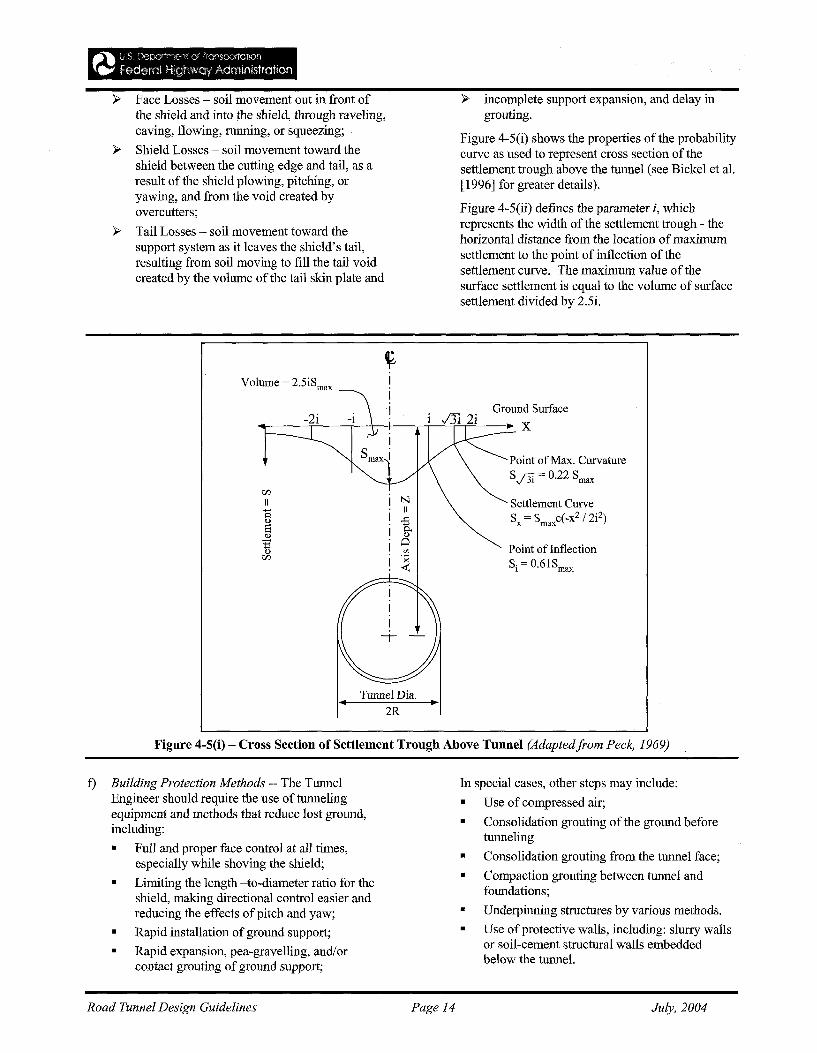
Volume = 2.5iSmax
Tunnel Dia...2R
~ incomplete support expansion, and delay ingrouting.
Figure 4-5(i) shows the properties of the probabilitycurve as used to represent cross section of thesettlement trough above the tunnel (see Bickel et al.[1996] for greater details).
Figure 4-5(ii) defines the parameter i, whichrepresents the width of the settlement trough - thehorizontal distance from the location of maximumsettlement to the point of inflection of thesettlement curve. The maximum value of thesurface settlement is equal to the volume of surfacesettlement divided by 2.5i.
Ground Surface
X
Point ofMax. CurvatureSJ3i = 0.22 Smax
Settlement CurveSx = Smaxe(-xZ / 2iz)
Point of InflectionSi = 0.6lSmax
Figure 4-5(i) - Cross Section of Settlement Trough Above Tunnel (Adaptedfrom Peck, 1969)
f) Building Protection Methods -- The TunnelEngineer should require the use of tunnelingequipment and methods that reduce lost ground,including:
• Full and proper face control at all times,especially while shoving the shield;
• Limiting the length -to-diameter ratio for theshield, making directional control easier andreducing the effects of pitch and yaw;
• Rapid installation of ground support;
• Rapid expansion, pea-gravelling, and/orcontact grouting ofground support;
Road Tunnel Design Guidelines Page 14
In special cases, other steps may include:
• Use of compressed air;
• Consolidation grouting of the ground beforetunneling
• Consolidation grouting from the tunnel face;
• Compaction grouting between tunnel andfoundations;
• Underpinning stIuctures by various methods.
• Use of protective walls, including: slurry wallsor soil-cement structural walls embeddedbelow the tunnel.
July, 2004
See Cording & Hansmire (1975) for detailedexamples of actual measurements of groundmovement about tunnels in sand;
See Palmer & Belshaw (1979, 1980) for detailedexamples of ground movement about tunnels inclay.
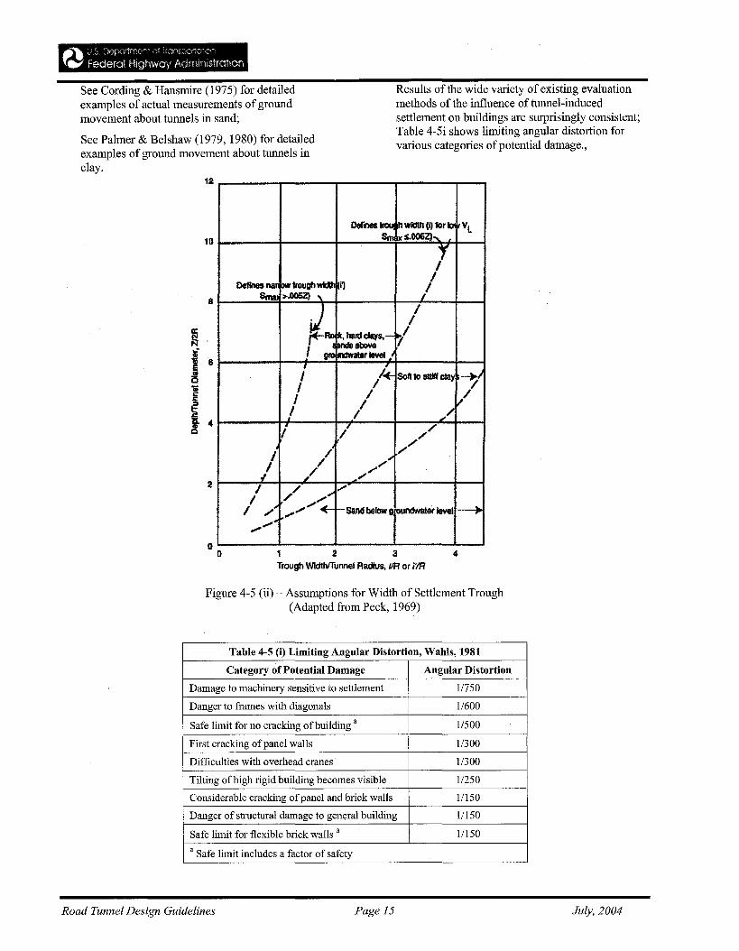
Results of the wide variety of existing evaluationmethods of the influence of tunnel-inducedsettlement on buildings are surprisingly consistent;Table 4-5i shows limiting angular distortion forvarious categories ofpotential damage.,
41 2 3Trough Wid1hlTunnel Radius. VR or i'IR
Oetines~ h wldtfl (Q for b ilLSm xs.OO5ZJ,
JDeffnesnafi M troughwidIh i')
ISma: >.0052} , /
~~I
I~. hard cIays,- ..l
I ~~atlove 7nclWater level J
I 4 Solt to sttlff Clay "7'I /I / ,//
/I I ~/
• / ,,;/I
I / ""-,,,'j / ".'"
,/ .".,/
I / ".
I / ,."".'"
/ /~ ,."".,."".,."". +- I-sand below g ounctNatef level ---+-,,""
"I}
I}
8
2
12
10
Figure 4-5 (ii) - Assumptions for Width of Settlement Trough(Adapted from Peck, 1969)
Table 4-5 (i) Limiting Angular Distortion, Wahls, 1981
Category of Potential Damage Angular Distortion
Damage to machinery sensitive to settlement 1/750
Danger to frames with diagonals 1/600
Safe limit for no cracking ofbuilding a 1/500
First cracking ofpanel walls 11300
Difficulties with overhead cranes 11300
Tilting ofhigh rigid building becomes visible 1/250
Considerable cracking ofpanel and brick walls 11150
Danger of structural damage to general building 1/150
Safe limit for flexible brick walls a 11150
a Safe limit includes a factor of safety
Road Tunnel Design Guidelines Page 15 July, 2004
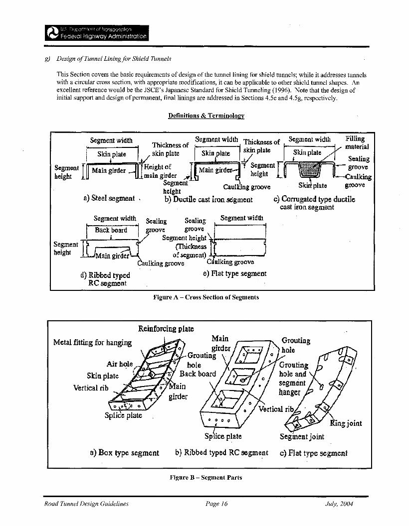
g) Design ofTunnel Liningfor Shield Tunnels
This Section covers the basic requirements of design of the tunnel lining for shield tunnels; while it addresses tunnelswith a circular cross section, with appropriate modifications, it can be applicable to other shield tunnel shapes. Anexcellent reference would be the JSCE's Japanese Standard for Shield Tunneling (1996). Note that the design ofinitial support and design ofpermanent, final linings are addressed in Sections 4.5e and 4.5g, respectively.
Definitions & Terminology
Fillingmaterial
Sealing-~- groove
-Caulkinggroove
Segment width
Skirt plate
. Segment width Thickness ofI Thickness of /- -, .I..t/ skin plate Skin plate -'plate
;""'-==:I..--"i'llHeiBftt of T~Main~1rd""1"T Se!!"'ent [main girder ....lJ height
Se~ent CauI~ng groove Skin: plateheIght -b) Ductile cast iron segment c) Corrugated type ductile
cast iron segmenta) Steel segment .
Segment width
I' 1Segment width Sc;aling Sealing
Back board "j groove grooveSegment height
(Thicknessof segment) 4~-----..I
aulking groove C vIking groove
e) Flat type segmentd) Ribbed typedRCsegment
Segmentheight
Figure A - Cross Section of Segments
Reinforcing plate
a) Box type segment
Segment joint
b) Ribbed typed RC segment c) Flat type segment
Maino girder
'''--''--", Grollting .hole
Back boardAi.r hole ._
• • .ALlo.__
Skin plate 1~~5!=i{
Vertical rib
Metal fitting for hanging
Figure B - Segment Parts
Road Tunnel Design Guidelines Page 16 July, 2004
Terminology
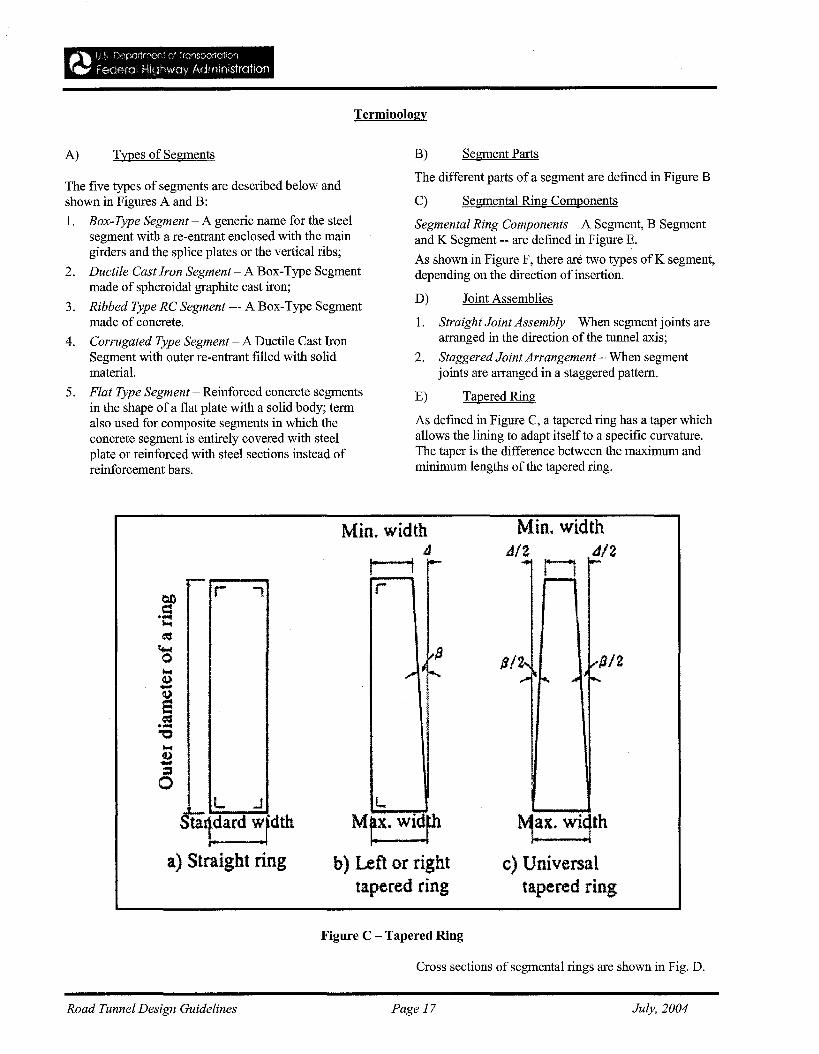
A) Types of Segments B) Segment Parts
The five types of segments are described below andshown in Figures A and B:
1. Box-Type Segment - A generic name for the steelsegment with a re-entrant enclosed with the maingirders and the splice plates or the vertical ribs;
2. Ductile Cast Iron Segment - A Box-Type Segmentmade of spheroidal graphite cast iron;
3. Ribbed Type RC Segment --- A Box-Type Segmentmade of concrete.
4. Corrugated Type Segment - A Ductile Cast IronSegment with outer re-entrant filled with solidmaterial.
5. Flat Type Segment - Reinforced concrete segmentsin the shape of a flat plate with a solid body; termalso used for composite segments in which theconcrete segment is entirely covered with steelplate or reinforced with steel sections instead ofreinforcement bars.
The different parts of a segment are defined in Figure B
C) Segmental Ring Components
Segmental Ring Components - A Segment, B Segmentand K Segment -- are defined in Figure E.
As shown in Figure F, there are two types ofK segment,depending on the direction of insertion.
D) Joint Assemblies
1. Straight Joint Assembly - When segment joints arearranged in the direction of the tunnel axis;
2. Staggered Joint Arrangement - When segmentjoints are arranged in a staggered pattern.
E) Tapered Ring
As defmed in Figure C, a tapered ring has a taper whichallows the lining to adapt itself to a specific curvature.The taper is the difference between the maximum andminimum lengths of the tapered ring.
r--_--...r
L .J
Statdard wJdth
a) Straight ring
Min. width4,.. '\-
r
L
Mt>'. Wl~fhb) Left or right
tapered ring
Figure C - Tapered Ring
Min. width11/2 d/2.... 11 .....
....--i
~~x. wi1th
c) Universaltapered ring
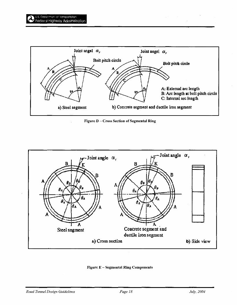
Cross sections of segmental rings are shown in Fig. D.
Road Tunnel Design Guidelines Page 17 July, 2004
_""\ L S L"112j::Klrtr·"w:)r" (.t 'rons/:K:tiON:""1
l".... Federal Highway Adrnlnisfratloo
Joint angelar
A: External arc lengthB: Arc length at bolt pitch circleC: Internal arc length
b) Concrete segment and ductile iron segment
Bolt pitch circle
Joint angel arI
a) Steel segment
Figure D - Cross Section of Segmental Ring
b) Side view
- Joint angle a t
AConcrete segment "andductile iron segment
a) Cross section
ASteel segment
Figure E - Segmental Ring Components
Road Tunnel Design Guidelines Page 18 July, 2004
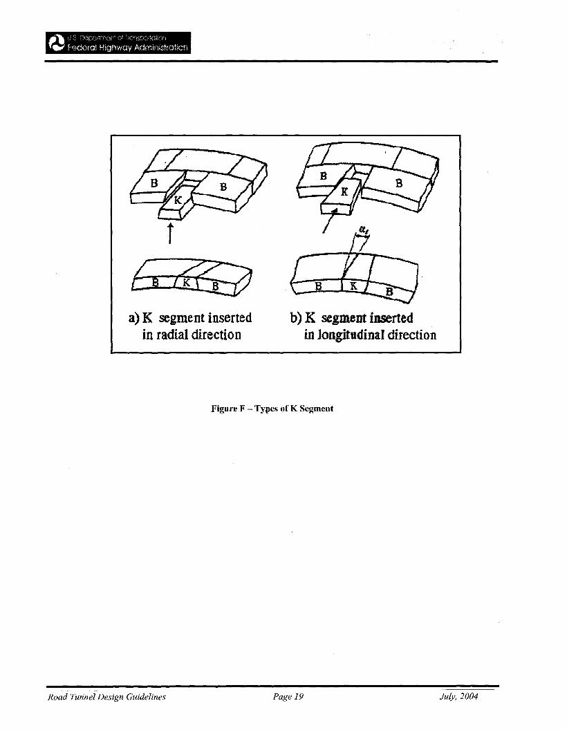
f
a) K segment insertedin radial direction
b) K segment insertedin longitudinal direction
Road Tunnel Design Guidelines
Figure F - Types of K Segment
Page 19 July, 2004
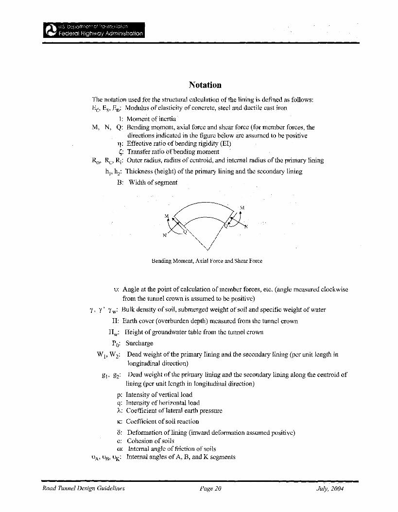
Notation
The notation used for the structural calculation of the lining is defined as follows:Eb Es' Eo: Modulus of elasticity of concrete, steel and ductile cast iron
I: Moment of inertiaM, N, Q: Bending mQment, axial force and shear force (for member forces, the
directions indicated in the figure below are assumed to be positive11: Effective ratio of bending rigidity (EI)l;: Transfer ratio of bending moment
Ro' Re, ~: Outer radius, radius of centroid, and internal radius of the primary lining
hj, h2: Thickness (height) of the primary lining and the secondary lining
B: Width of segment
Bending Moment, Axial Force and Shear Force
u: Angle at the point of calculation of member forces, etc. (angle measured clockwise
from the tunnel crown is assumed to be positive)
y, y' y w: Bulk density of soil, submerged weight of soil and specific weight of water
H: Earth cover (overburden depth) measured from the tunnel crown
Hw: Height of groundwater table from the tunnel crown
Po: Surcharge
W l' W2: Dead weight of the primary lining and the secondary lining (per unit length inlongitudinal direction)
gl' g2: Dead weight of the primary lining and the secondary lining along the centroid of
lining (per unit length in longitudinal direction)
p: Intensity of vertical loadq: Intensity ofhorizontal load1.,: Coefficient of lateral earth pressure
K: Coefficient of soil reaction
8: Deformation oflining (inward deformation assumed positive)c: Cohesion of soilsco: Internal angle of friction of soils
uA, 1.13, ut<.: Internal angles ofA, B, and K segments
Road Tunnel Design Guidelines Page 20 July, 2004
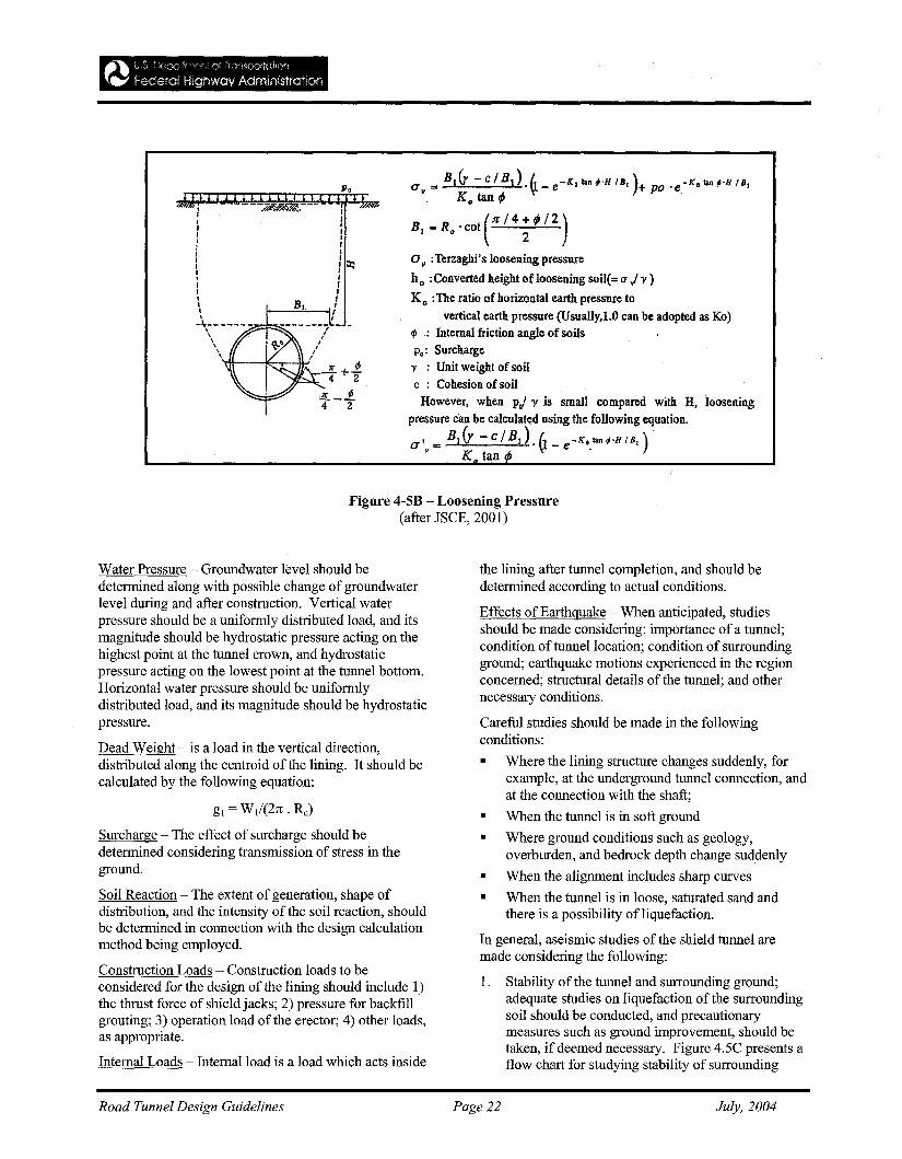
for H > 1-2 Do, and tunnel in stiffclay with N > 8
Cohesive Soil -
Figure 4-5B summarizes the loosening pressure.
The loosening width for sections other than the circlecan also be calculated from the expression ofTerzaghi,if the loosening width (Bl) can be suitably evaluated.However, in such cases, the distribution of the loadneeds to be carefully decided as it may vary accordingto the configuration of the tunnel cross section. Forsuch cases the designer should refer to results of fieldmeasurements along with data on earth pressure andgroundwater pressure, etc, in similar ground conditions.
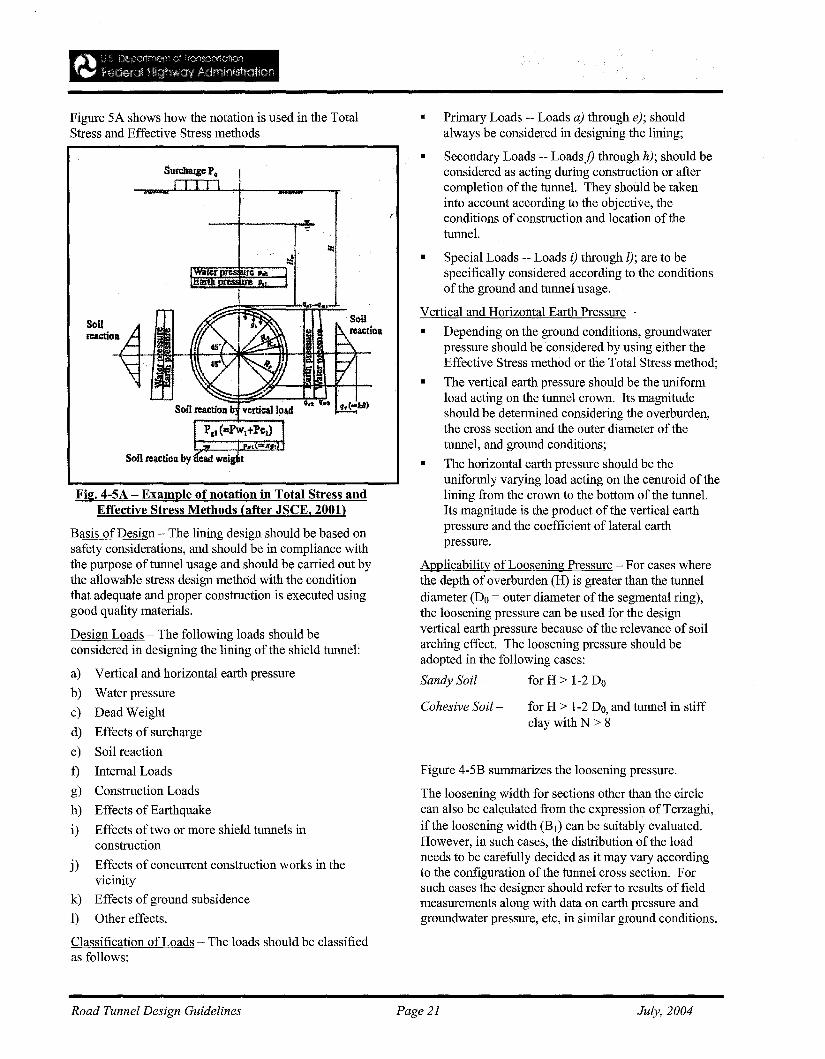
• Primary Loads -- Loads a) through e); shouldalways be considered in designing the lining;
• Secondary Loads -- Loadsj) through h); should beconsidered as acting during construction or aftercompletion of the tunnel. They should be takeninto account according to the objective, theconditions of construction and location of thetunnel.
• Special Loads -- Loads i) through l); are to bespecifically considered according to the conditionsof the ground and tunnel usage.
Vertical and Horizontal Earth Pressure -
• Depending on the ground conditions, groundwaterpressure should be considered by using either theEffective Stress method or the Total Stress method;
• The vertical earth pressure should be the uniformload acting on the tunnel crown. Its magnitudeshould be determined considering the overburden,the cross section and the outer diameter of thetunnel, and ground conditions;
• The horizontal earth pressure should be theuniformly varying load acting on the centroid of thelining from the crown to the bottom of the tunnel.Its magnitude is the product of the vertical earthpressure and the coefficient of lateral earthpressure.
Applicability of Loosening Pressure - For cases wherethe depth of overburden (H) is greater than the tunneldiameter (Do = outer diameter of the segmental ring),the loosening pressure can be used for the designvertical earth pressure because of the relevance of soilarching effect. The loosening pressure should beadopted in the following cases:
Sandy Soil- for H > 1-2 Do
Construction Loads
Effects of Earthquake
Effects of two or more shield tunnels inconstruction
Soil reaction by eal! wei t
Fig. 4-5A - Example of notation in Total Stress andEffective Stress Methods (after JSCE, 2001)
Basis of Design - The lining design should be based onsafety considerations, and should be in compliance withthe purpose of tunnel usage and should be carried out bythe allowable stress design method with the conditionthat adequate and proper construction is executed usinggood quality materials.
Design Loads - The following loads should beconsidered in designing the lining of the shield tunnel:
a) Vertical and horizontal earth pressure
b) Water pressure
c) Dead Weight
d) Effects of surcharge
e) Soil reaction
f) Internal Loads
g)
h)
i)
Figure 5A shows how the notation is used in the TotalStress and Effective Stress methods
j) Effects of concurrent construction works in thevicinity
k) Effects of ground subsidence
1) Other effects.
Classification of Loads - The loads should be classifiedas follows:
Road Tunnel Design Guidelines Page 21 July, 2004
I ------:j7"~.----
IIIIIIIIIIIII,I
-\,- - - -- --"'-;..-0......."\\
'.\
PoCI ". Bier - c / B1).t. _ e-lColan;'H IB,)+ po 'e.-lColan;'H IB,
v. Ko tan tP Y.
B".R 'cot(Jr/4+ tP /2)I 0 2
O. :Terzaghi's loosening pressure
h0 : Converted height of loosening soil(=a vi l' )
K o :The ratio ofhorizontal earth pressure tovertical earth pressure (Usually,loO can be adopted as Ko)
q,: Internal friction angle of soilsPo: Surchargel' : Unit weight of soilc : Cohesion of soil
However, when prJ l' is small compared with H, looseningpressure can be calculated using the following equation.
a'. = HI(r - c I HI). (1- e-lCo.lan;'H 18, )
K tan
Figure 4-5B - Looseuing Pressure(after JSCE, 2001)
Water Pressure - Groundwater level should bedetermined along with possible change ofgroundwaterlevel during and after construction. Vertical waterpressure should be a uniformly distributed load, and itsmagnitude should be hydrostatic pressure acting on thehighest point at the tunnel crown, and hydrostaticpressure acting on the lowest point at the tunnel bottom.Horizontal water pressure should be uniformlydistributed load, and its magnitude should be hydrostaticpressure.
Dead Weight - is a load in the vertical direction,distributed along the centroid of the lining. It should becalculated by the following equation:
gl = W1/(2rc . Rc)
Surcharge - The effect of surcharge should bedetermined considering transmission of stress in theground.
Soil Reaction - The extent ofgeneration, shape ofdistribution, and the intensity of the soil reaction, shouldbe determined in connection with the design calculationmethod being employed.
Construction Loads - Construction loads to beconsidered for the design of the lining should include 1)the thrust force of shield jacks; 2) pressure for backfillgrouting; 3) operation load of the erector; 4) other loads,as appropriate.
Internal Loads - Internal load is a load which acts inside
the lining after tunnel completion, and should bedetermined according to actual conditions.
Effects of Earthquake - When anticipated, studiesshould be made considering: importance of a tunnel;condition of tunnel location; condition of surroundingground; earthquake motions experienced in the regionconcerned; structural details of the tunnel; and othernecessary conditions.
Careful studies should be made in the followingconditions:
• Where the lining structure changes suddenly, forexample, at the underground tunnel connection, andat the connection with the shaft;
• When the tunnel is in soft ground
• Where ground conditions such as geology,overburden, and bedrock depth change suddenly
• When the alignment includes sharp curves
• When the tunnel is in loose, saturated sand andthere is a possibility ofliquefaction.
In general, aseismic studies of the shield tunnel aremade considering the following:
1. Stability of the tunnel and surrounding ground;adequate studies on liquefaction of the surroundingsoil should be conducted, and precautionarymeasures such as ground improvement, should betaken, if deemed necessary. Figure 4.5C presents aflow chart for studying stability of surrounding
Road Tunnel Design Guidelines Page 22 July, 2004
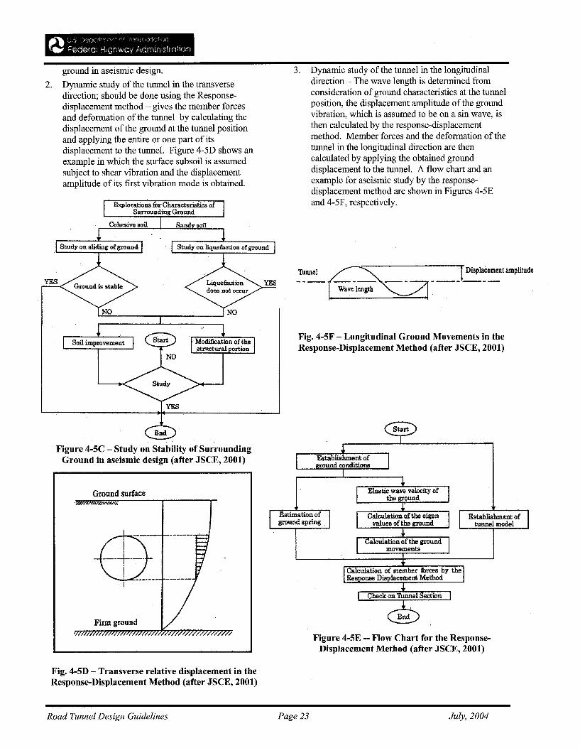
Figure 4-5E -- Flow Chart for the ResponseDisplacement Method (after JSCE, 2001)
Establishment oftunnel model
Fig. 4-5F - Longitudinal Ground Movements in theResponse-Displacement Method (after JSCE, 2001)
::""~.__. _. _rDiSPla~~ntamPliludeWavelength
3. Dynamic study of the tunnel in the longitudinaldirection - The wave length is determined fromconsideration of ground characteristics at the tunnelposition, the displacement amplitude of the groundvibration, which is assumed to be on a sin wave, isthen calculated by the response-displacementmethod. Member forces and the deformation of thetunnel in the longitudinal direction are thencalculated by applying the obtained grounddisplacement to the tunnel. A flow chart and anexample for aseismic study by the responsedisplacement method are shown in Figures 4-5Eand 4-5F, respectively.
Estimation ofground spring.
/.
Cohesive soil Sand soil
ground in aseismic design.
2. Dynamic study of the tunnel in the transversedirection; should be done using the Responsedisplacement method - gives the member forcesand deformation of the tunnel by calculating thedisplacement of the ground at the tunnel positionand applying the entire or one part of itsdisplacement to the tunnel. Figure 4-5D shows anexample in which the surface subsoil is assumedsubject to shear vibration and the displacementamplitude of its first vibration mode is obtained.
Figure 4-5C - Study on Stability of SurroundingGround in aseismic design (after JSCE, 2001)
e! ------ --------
---+--j
Firm ground
N •
&;plorations ror'Characteristics ofSurrounding Ground
Ground surface
Fig. 4-5D - Transverse relative displacement in theResponse-Displacement Method (after JSCE, 2001)
Road Tunnel Design Guidelines Page 23 July, 2004
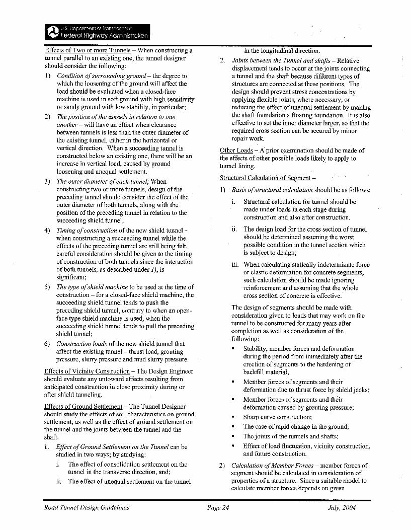
Effects of Two or more Tunnels - When constructing atunnel parallel to an existing one, the tunnel designershould consider the following:
1) Condition ofsurrounding ground - the degree towhich the loosening of the ground will affect theload should be evaluated when a closed-facemachine is used in soft ground with high sensitivityor sandy ground with low stability, in particular;
2) The position ofthe tunnels in relation to oneanother - will have an effect when clearancebetween tunnels is less than the outer diameter ofthe existing tunnel, either in the horizontal orvertical direction. When a succeeding tunnel isconstructed below an existing one, there will be anincrease in vertical load, caused by groundloosening and unequal settlement.
3) The outer diameter ofeach tunnel; Whenconstructing two or more tunnels, design of thepreceding tunnel should consider the effect of theouter diameter ofboth tunnels, along with theposition of the preceding tunnel in relation to thesucceeding shield tunnel;
4) Timing ofconstruction of the new shield tunnelwhen constructing a succeeding tunnel while theeffects of the preceding tunnel are still being felt,careful consideration should be given to the timingofconstruction of both tunnels since the interactionofboth tunnels, as described under 1), issignificant;
5) The type ofshield machine to be used at the time ofconstruction - for a closed-face shield machine, thesucceeding shield tunnel tends to push thepreceding shield tunnel, contrary to when an openface type shield machine is used, when thesucceeding shield tunnel tends to pull the precedingshield tunnel;
6) Construction loads of the new shield tunnel thataffect the existing tunnel- thrust load, groutingpressure, slurry pressure and mud slurry pressure.
Effects of Vicinity Construction - The Design Engineershould evaluate any untoward effects resulting fromanticipated construction in close proximity during orafter shield tunneling.
Effects of Ground Settlement - The Tunnel Designershould study the effects of soil characteristics on groundsettlement; as well as the effect of ground settlement onthe tunnel and the joints between the tunnel and theshaft.
1. Effect ofGround Settlement on the Tunnel can bestudied in two ways; by studying:
i. The effect of consolidation settlement on thetunnel in the transverse direction, and;
11. The effect of unequal settlement on the tunnel
in the longitudinal direction.
2. Joints between the Tunnel and shafts - Relativedisplacement tends to occur at the joints connectinga tunnel and the shaft because different types ofstructures are connected at these positions. Thedesign should prevent stress concentrations byapplying flexible joints, where necessary, orreducing the effect of unequal settlement by makingthe shaft foundation a floating foundation. It is alsoeffective to set the inner diameter larger, so that therequired cross section can be secured by minorrepair work.
Other Loads - A prior examination should be made ofthe effects of other possible loads likely to apply totunnel lining..
Structural Calculation of Segment-
1) Basis ofstructural calculation should be as follows:
i. Structural calculation for tunnel should bemade under loads in each stage duringconstruction and also after construction.
ii. The design load for the cross section of tunnelshould be determined assuming the worstpossible condition in the tunnel section whichis subject to design;
iii. When calcula,ting statically indeterminate forceor elastic deformation for concrete segments,such calculation should be made ignoringreinforcement and assuming that the wholecross section of concrete is effective.
The design of segments should be made withconsideration given to loads that may work on thetunnel to be constructed for many years aftercompletion as well as consideration of thefollowing:
• Stability, member forces and deformationduring the period from immediately after theerection of segments to the hardening ofbackfill material;
• Member forces of segments and theirdeformation due to thrust force by shield jacks;
• Member forces of segments and theirdeformation caused by grouting pressure;
• Sharp curve construction;
• The case of rapid change in the ground;
• The joints of the tunnels and shafts;
• Effect ofload fluctuation, vicinity construction,and future construction.
2) Calculation ofMember Forces - member forces ofsegment should be calculated in consideration ofproperties of a structure. Since a suitable model tocalculate member forces depends on given
Road Tunnel Design Guidelines Page 24 July, 2004
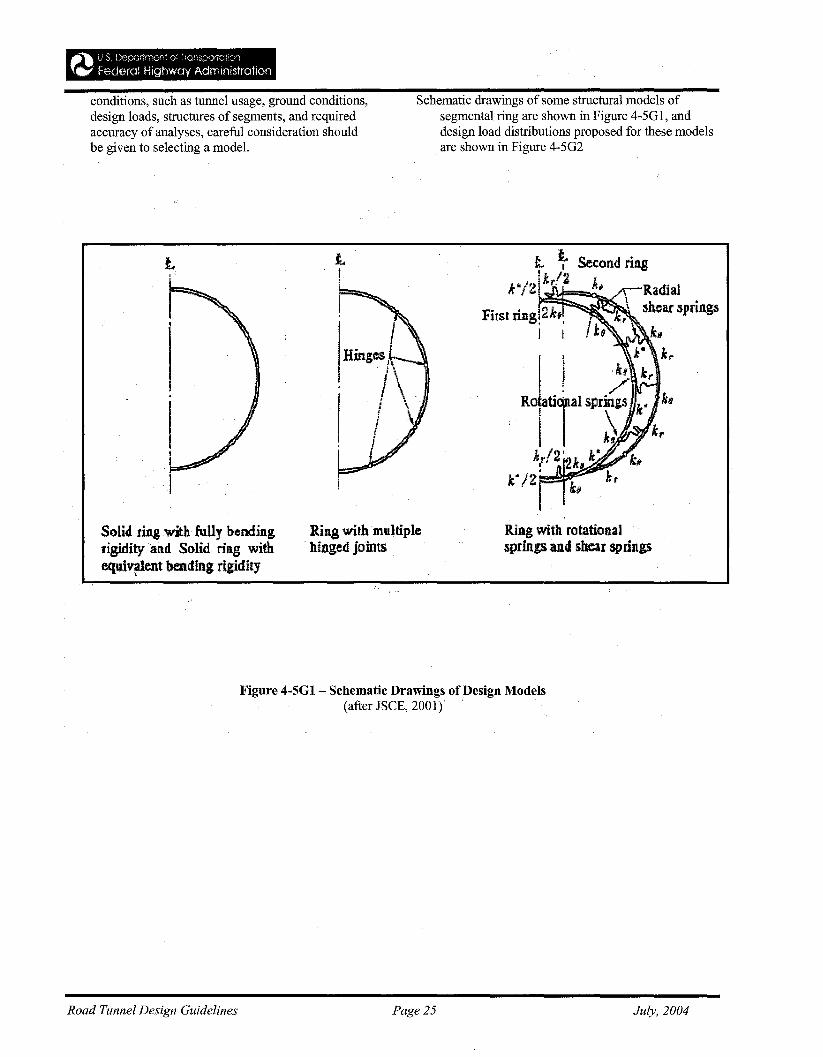
conditions, such as tunnel usage, ground conditions,design loads, structures of segments, and requiredaccuracy of analyses, careful consideration shouldbe given to selecting a model.
Schematic drawings of some structural models ofsegmental ring are shown in Figure 4-5G1, anddesign load distributions proposed for these modelsare shown in Figure 4-5G2
L
Solid ring with fully bendins;rigidityatld Solid ring withequiv,1.ent bending rigidity
Ring with multiplehinged joints
Rin.g with rotatioaal.springs and shear springs
Road Tunnel Design Guidelines
Figure 4-5G1 - Schematic Drawings of Design Models(after JSCE, 2001)
Page 25 July, 2004
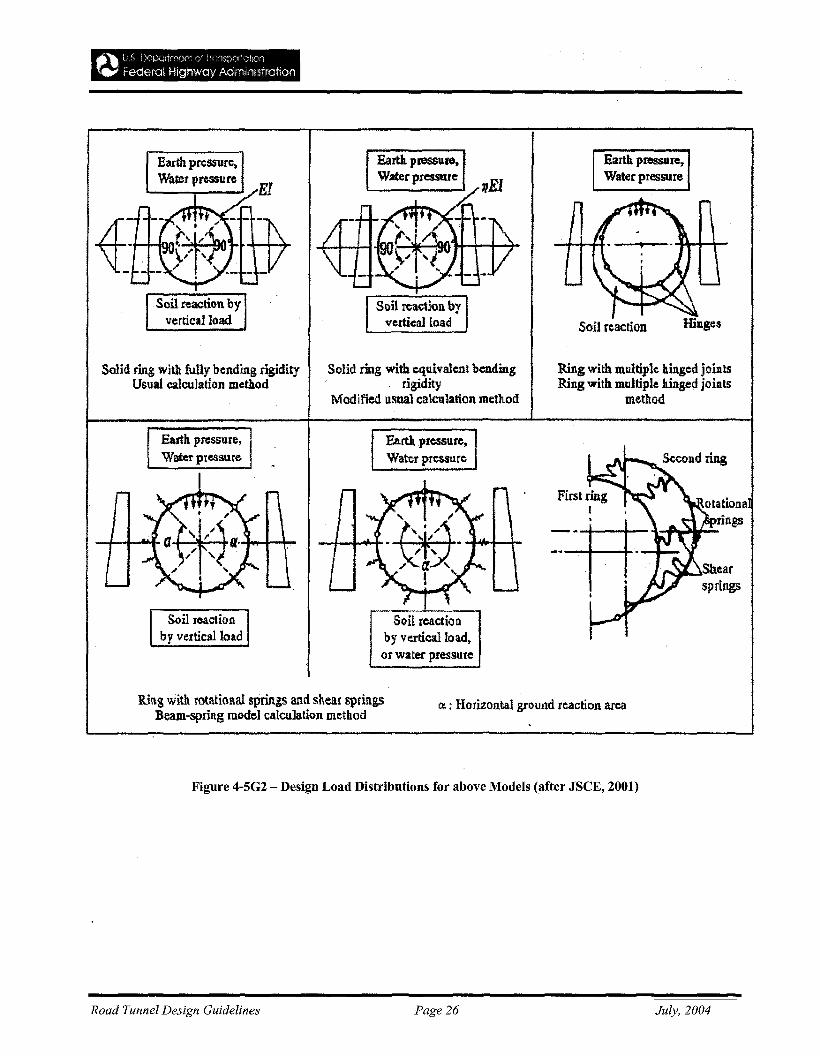
Earth pressure,Watet pressure
Solid ring with fully hending rigidityUsual calculation method
Earth pressure.Water pressure
Earth p.ressure.Water pressure
Solid ring with equivalent bendingrigidity
Modified usual calculation method
Earth pressure,Water pressure
Soil rcac:tiolby vertical1oa~
or water pressure
Earth pressure.Water pressure
Soil reaction
Ring with multiple hinged jointsRing with multiple hinged joints
method
Ril\g with rotational springs and shear springsBeam-spring model calculalion method
ell : Horizontal ground rcactiO.R area
Figure 4-5G2 - Design Load Distributions for above Models (after JSCE, 2001)
Road Tunnel Design Guidelines Page 26 July, 2004
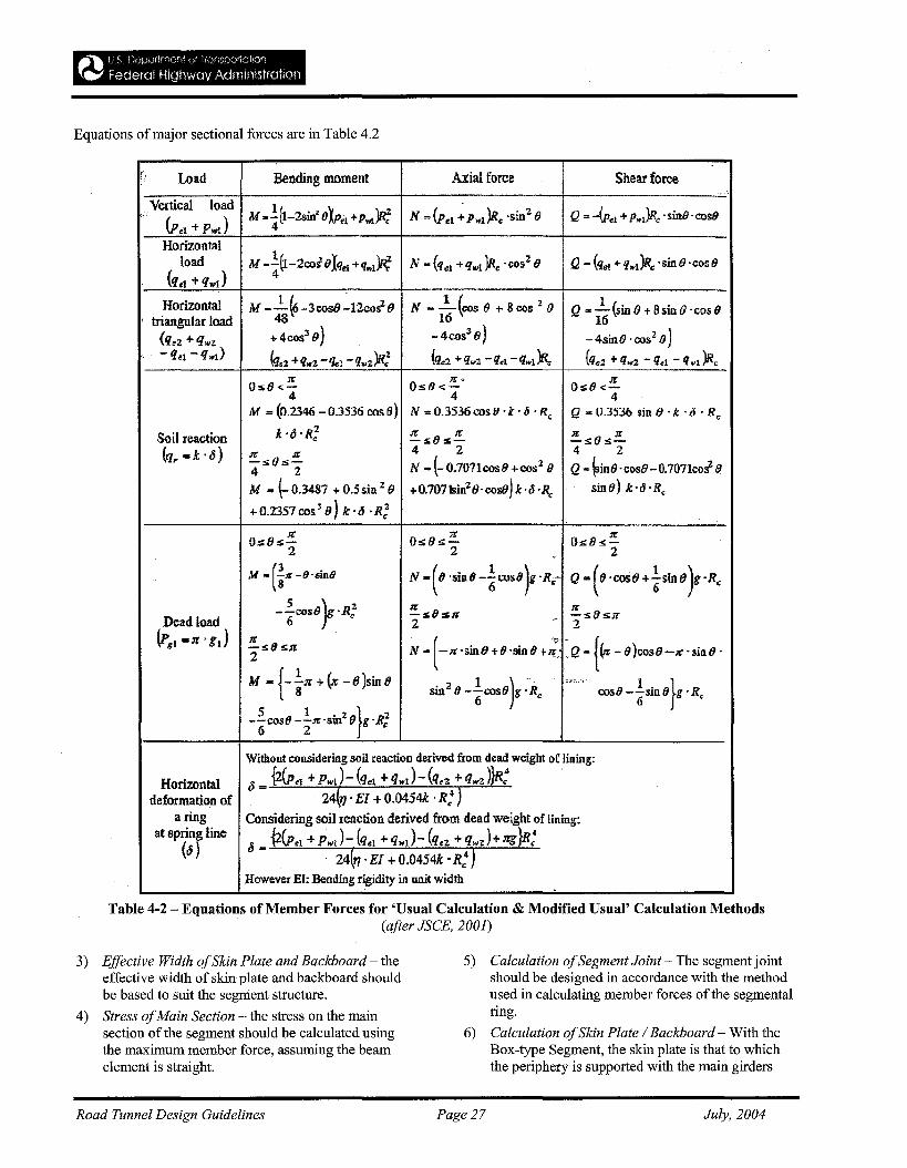
Equations of major sectional forces are in Table 4.2
, Load Bending moment Axial force Shear force
Vertical loadM ...!.(l_2sin" exPel ~P104)R; N .. (pel ~PwI)Rc 'sinze Q .. -(Pel +P",l)Rc •sinB 'cosO
(Pel + Pwt) 4
Horizontalload M • .!.(1-2coS'OXqel +qwl)R; N -{qel +qwl)Rc ·cosz(J Q - (qel + q.,l)Rc 'sinO 'cos8
(qel + qwl) 4
Horizontal M --..!..(6-3COS8~12CO~(J N - 1-(C05 e + 8 cos 2(J Q .. -..!..(sinO+8sinO·CQsOtriangular load 48 16 16
(qez + Qw2 + 4cos3 0) -4C053 0) -4sinO ·oos2 0)
-q"1 -q.,l) (q.:z +q..z -Q"l -q..z)R; (q..2 +Q",2 -qe1-Qwt)R. {q.,z +q..z -qd -q..t)Re
Os8«;!!.T{;".
Os8<.T{;Os8 <.-4 4 4
M = (0.2346 - 0.3536 cos B) N .. 0.3536 cos 1:1 •k • ., •Ro Q .. 0.3536 sin 0 •k . 0 . Ro
Soil reaction k'!5'R; !!. s (J s!E. !!.s(Js!!..(q,. =k '6) !!.:ra(Js!E.
4 2 4 2
N - (- 0.7071cos8 + cos2 8 Q - ~inO' cosO - O.7071co~ 94 2
M "" (- 0.3481 + 0.5 sin 2 e +O.707kin2 e.cosej k·6·R" sinfJ) k·"·R.
+0.2357 COS3 8) k·o .R;
Os8sl!. Oso,,!. o"es;!2 2 . 2
M -(iZ-9.sin8 N • (8 'sin 8 -~COS8 )g.Re- Q • (0 ·cost) +iSin tJ )g'Rc
S f2 !!.so :!iR !!.sfJ SOT{;--cos8 ·RDead load 6 c 2 - 2
(Fgt -n' gIl ;!sOs,n ( ..~ ~Q - {(;r -8 )COSO-R' sill 0 .2 N - -R'sinO+e'sine+~
M - {- in + (z - e)sin esin2 8 -iCOS09)g.Re
';J;;Io'.7•• ","
cosO -iSin 09}g .He
5 1 .:z} 2--cosO --.n; .SIn fJ g'~6 2
Without cousidering soil reaction derived from dead weight of lining:
Horizontal 6 _ {2(p<t + PW1)- (qet +qwt)-(q.z +qwz)}R:
deformation of - 24(1J .EI + O.0454k .R: )a ring Considering soil reaction derived from dead weight of lining:
at spring line 6{2(pd + PwJ-(q,,! ~q..J-(q'2 +qwz)+Jtg}R.4
(6 )-. . 24(11' EI +O.0454k •R: J
However EI: Bending rigidity in unit width
Table 4-2 - Equations of Member Forces for 'Usual Calculation & Modified Usual' Calculation Methods(after JSCE, 2001)
3) Effective Width ofSkin Plate and Backboard - theeffective width of skin plate and backboard shouldbe based to suit the segment structure.
4) Stress ofMain Section - the stress on the mainsection of the segment should be calculated usingthe maximum member force, assuming the beamelement is straight.
5) Calculation ofSegment Joint - The segment jointshould be designed in accordance with the methodused in calculating member forces of the segmentalring.
6) Calculation ofSkin Plate / Backboard - With theBox-type Segment, the skin plate is that to whichthe periphery is supported with the main girders
Road Tunnel Design Guidelines Page 27 July, 2004
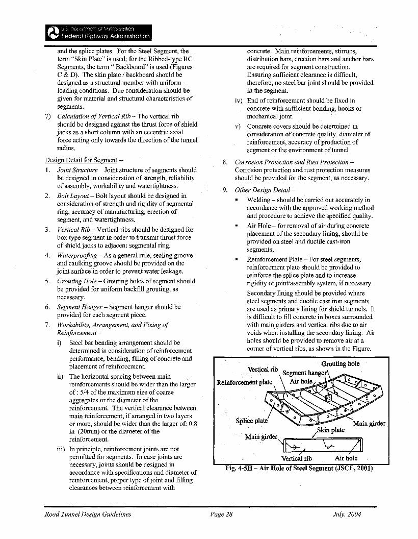
/SkinplateMairi.girder~:~
lL:!:/~_~_\; ;711Vertical rib Air hole
Fig. 4-5H - Air Hole of Steel Segment (JSCE, 2001)
concrete. Main reinforcements, stirrups,distribution bars, erection bars and anchor barsare required for segment construction.Ensuring sufficient clearance is difficult,therefore, no steel bar joint should be providedin the segment.
iv) End of reinforcement should be fixed inconcrete with sufficient bonding, hooks ormechanical joint.
v) Concrete covers should be determined inconsideration of concrete quality, diameter ofreinforcement, accuracy ofproduction ofsegment or the environment of tunnel
8. Corrosion Protection and Rust Protection Corrosion protection and rust protection measuresshould be provided for the segment, as necessary.
9. Other Design Detail-
• Welding - should be carried out accurately inaccordance with the approved working methodand procedure to achieve the specified quality.
• Air Hole ~ for removal ofair during concreteplacement of the secondary lining, should beprovided on steel and ductile cast-ironsegments;
• Reinforcement Plate - For steel segments,reinforcement plate should be provided toreinforce the splice plate and to increaserigidity ofjoint/assembly system, if necessary.
Secondary lining should be provided wheresteel segments and ductile cast iron segmentsare used as primary lining for shield tunnels. Itis difficult to fill concrete in boxes surroundedwith main girders and vertical ribs due to airvoids when installing the secondary lining. Airholes should be provided to remove air at acomer ofvertical ribs, as shown in the Figure.
and the splice plates. For the Steel Segment, theterm "Skin Plate" is used; for the Ribbed-type RCSegments, the term" Backboard" is used (FiguresC & D). The skin plate / backboard should bedesigned as a structural member with uniformloading conditions. Due consideration should begiven for material and structural characteristics ofsegments.
7) Calculation ofVertical Rib - The vertical ribshould be designed against the thrust force of shieldjacks as a short column with an eccentric axialforce acting only towards the direction of the tunnelradius.
Design Detail for Segment --
I. Joint Structure - Joint structure of segments shouldbe designed in consideration of strength, reliabilityof assembly, workability and watertightness.
2. Bolt Layout - Bolt layout should be designed inconsideration of strength and rigidity of segmentalring, accuracy ofmanufacturing, erection ofsegment, and watertightness.
3. Vertical Rib - Vertical ribs should be designed forbox type segment in order to transmit thrust forceof shield jacks to adjacent segmental ring.
4. Waterproofing - As a general rule, sealing grooveand caulking groove should be provided on thejoint surface in order to prevent water leakage.
5. Grouting Hole - Grouting holes of segment shouldbe provided for uniform backfill grouting, asnecessary.
6. Segment Hanger - Segment hanger should beprovided for each segment piece.
7. Workability, Arrangement, and Fixing ofReinforcement -
i) Steel bar bending arrangement should bedetermined in consideration ofreinforcementperformance, bending, filling of concrete andplacement of reinforcement.
ii) The horizontal spacing between mainreinforcements should be wider than the largerof: 5/4 of the maximum size of coarseaggregates or the diameter of thereinforcement. The vertical clearance betweenmain reinforcement, if arranged in two layersor more, should be wider than the larger of: 0.8in (20mm) or the diameter of thereinforcement.
iii) In principle, reinforcement joints are notpermitted for segments. In case joints arenecessary, joints should be designed inaccordance with specifications and diameter ofreinforcement, proper type ofjoint and fillingclearances between reinforcement with
Road Tunnel Design Guidelines Page 28 July, 2004
h) TunnelJacking
1. Introduction
Tunnel jacking is used to construct large shallowunderground openings beneath facilities that must bekept in service during construction. The method, whichevolved from pipe jacking, is generally used in softground for relatively short lengths of tunnel, whereTBM or cut-and-cover methods would be less desirable.
The technique of tunnel jacking is not new, but in recentyears it has been used to construct openings primarily inEurope and Asia, often under railroad lines andhighways.
Until recently, when it was used on the Central Artery /Tunnel project (CA/T) in Boston, the method has hadlimited use in the United States. However, its use onthe CA/T project was the largest application of its kindin the world, resulting in several awards and accolades.
Ropkins (1999) and Taylor & Winsor (1999) areexcellent references on design and construction ofjacked tunnels.
ii. Technique SelectionSelection of the Technique should consider thefollowing:
,/ Required tunnel clearance envelope
,/ Requirement for services within the completedtunnel
,/ Driver sight lines
,/ Acceptable amount of disturbance to theoverlying facility
,/ Ability to re-level or adjust the overlyingfacility periodically during construction
,/ Optimum depth from ground surface to the topof the tunnel
,/ Ground conditions both for stability at thetunnel face and for provision of the requiredjacking force to install the tunnels
,/ Maintenance provisions to the completedtunnel
,/ Details ofany abutting structures or tunnels
,/ ArchitecturaVaesthetic requirements
,/ Health and safety of construction staff.
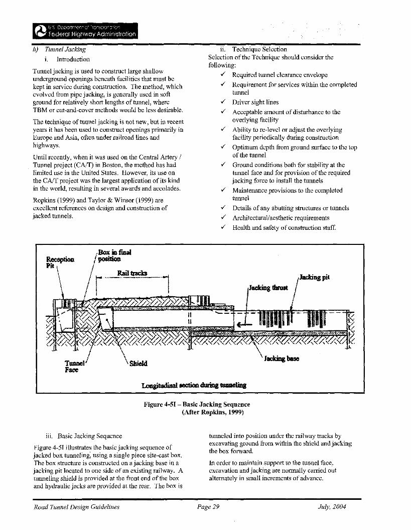
TmmellFace
~~~~~
\SbieId
Figure 4-51 - Basic Jacking Sequence(After Ropkins, 1999)
iii. Basic Jacking Sequence
Figure 4-51 illustrates the basic jacking sequence ofjacked box tunneling~ using a single piece site-cast box.The box structure is constructed on a jacking base in ajacking pit located to one side of an existing railway. Atunneling shield is provided at the front end of the boxand hydraulic jacks are provided at the rear. The box is
tunneled into position under the railway tracks byexcavating ground from within the shield and jackingthe box forward.
In order to maintain support to the tunnel face,excavation and jacking are normally carried outalternately in small increments of advance.
Road Tunnel Design Guidelines Page 29 July, 2004
iv. Design
Ground Drag --
Design should include provisions for controlling downdrag. An excellent solution for the longer boxes is theAnti-drag System (ADS), discussed by Ropkins (1999),which effectively separates the external surface of thebox from the adjacent ground during tunneling.
The ADS is an array of closely-spaced wire ropes whichare initially stored within the box with one end of eachrope anchored at the jacking pit. As the box advances,the ropes are progressively drawn out through guideholes in the shield and form a stationary separation layerbetween the moving box and the adjacent ground. Thedrag forces are absorbed by the ADS and transferredback to the jacking pit. In this manner the ground isisolated from drag forces and remains largelyundisturbed.
Vertical Alignment
Design should also include provisions for controllingvertical alignment. A long box has directional stabilityby virtue of its large length to depth ratio. The box isguided during the early stages of installation by its selfweight acting on the jacking base. Beyond the jackingbase, the bottom ADS 'tracks' maintain the box on acorrect vertical alignment. As the pressure on theground under the 'tracks' is normally less than or similarto the pre-existing pressure in the ground and aslocalized disturbance of the ground is eliminated, nosettlement of the tracks can occur. Any tendency for thebox to dive is thereby prevented.
In the case of a short box or series of short boxes, it isnecessary to steer each box by varying the elevation ofthe jacking thrust. This is done by arranging groups ofjacks at each jacking station at different elevationswithin the height of the box and by selectively isolatingindividual groups. The jacking process is complicatedby the need to check, at each stage of the operation, thealignment of all box units and if necessary to employ asuitable steering response at all jacking stations.
Horizontal Alignment
Design should also include provisions for controllinghorizontal alignment. As discussed previously undervertical alignment, a long box has a degree ofdirectional stability by virtue of its length to width ratio,and is normally guided during the early stages ofinstallation by fixed guides located on the jacking basealong both sides of the box. Where appropriate,steerage may also be used and is normally provided byselectively isolating one or more groups of thrust jackslocated across the rear of the box.
In the case of a short box or series of short boxes, fixedside guides are also appropriate but more reliance has tobe placed on steerage.
Face Loss
Design should also include provisions for controllingface loss which occurs when the ground ahead of theshield moves towards the tunnel as a result of reductionin lateral pressure in the ground at the tunnel face. Withface loss, as the tunnel advances, a greater volume ofground is excavated than that represented by thetheoretical volume displaced by the tunnel advance.
In cohesive ground, face loss is controlled by supportingthe face at all times by means of a specifically-designedtunneling shield and by careful control of both faceexcavation and box advance. The shield is normallydivided into cells by internal walls and shelves whichare pushed firmly into the face. Typically 0.5 ft(150mm) of soil is trimmed from the face followingwhich the box is jacked forward 0.5 ft (150mm). Thissequence is repeated until the tunneling operation iscomplete, thus maintaining the necessary support to theface.
The ground may need to be stabilized in advance of thetunneling operation, where the ground is weak or wherethere is high water table or artesian pressure.Techniques for stabilizing ground include: grouting,well point dewatering, and freezing.
The Tunnel Designer should ensure that groundtreatment measures do not in themselves cause anunacceptable degree of ground disturbance and surfacemovement.
Overcut
Design should also include provisions for controllingovercut in soft ground, by ensuring that the shieldperimeter is kept buried and cuts the ground to therequired profile. However, a degree of over-cut at theroof and sides beyond the nominal dimensions ofthebox is required for two reasons:
1. The hole through which the box travels must belarge enough to accommodate irregularities in theexternal surfaces of the box;
2. It is desirable to reduce contact pressures betweenthe ground and the box, to reduce drag.
The amount of over-cut required should be minimized ifunnecessary ground disturbance and surface settlementis to be avoided. This demands that the externalsurfaces of the box be formed as accurately as possible.Typical forming tolerances are: ± 0.4 in (10mm) at thebottom and ± 0.6 in (15mm) at the walls and roof.
Road Tunnel Design Guidelines Page 30 July, 2004
Tunneling Operation
The jacked box tunneling operation must be carefullymonitored and controlled to ensure proper performanceand safety. Throughout the tunneling operation,movements at the ground surface over the area affectedby the tunneling operation, jacking forces and boxalignments are all regularly monitored and compared topredicted or specified values.
The jacking operation can be adjusted based on themonitoring data.
Box Jacking & ADS Loads
Interface Drag Loads -- Soil/box contact pressures arecalculated and multiplied by appropriate friction factors,and are used to estimate drag loads at frictionalinterfaces; an appropriate adhesion value is used at theinterface between the box and cohesive ground.
Jacking Load -- The ultimate bearing pressures on theface supports and on the shield perimeter are used tocalculate the jacking load required to advance theshield.
ADS Loads - Simplifying assumptions are made indeveloping ADS loads and modeling box/ADS/soilinteraction, the validity of which is done by backanalyses ofloads and other historical data.
Jacking Thrust
Jacking thrust is provided by means of specially builthigh capacity hydraulic jacking equipment. Jacks of
500 tons (4,448 kN) or more can be utilized on largetunnels. Sufficient capacity is provided, via multiplejacks, to allow for steerage control and for possibleinaccuracies in the assessment ofjacking loads.
Reaction to the jacking thrust developed is provided byeither a jacking base or a thrust wall, depending on thesite topography and the relative elevation of the tunnel.These temporary structures must in turn transmit thethrust into a stable mass of adjacent ground.
A jacking base is normally stabilized by shearinteraction with the ground below and on each side.Where the interface is frictional, the interaction may beenhanced by surcharging the jacking base by means ofpre-stressed ground anchors or compacted tunnel spoil.The jacking base is also stabilized by both the top andbottom ADS which are anchored to it.
A thrust wall is normally stabilized by passive groundpressure. In developing this reaction, the wall maymove into the soil and this movement must be taken intoaccount when designing the jacking system. When athrust wall is used in a vertical sided jacking pit, care isrequired to ensure that movement of the thrust wallunder load does not cause any lack of stabilityelsewhere in the pit.
Road Tunnel Design Guidelines Page 31 July, 2004
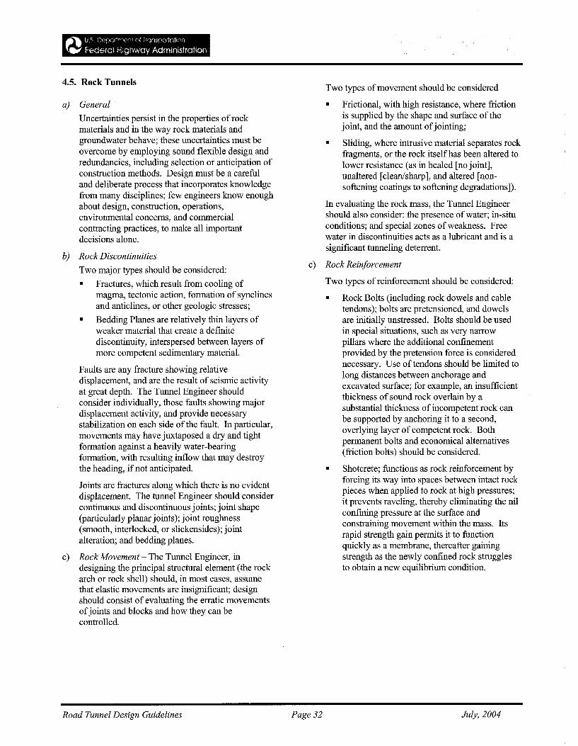
4.5. Rock Tunnels
a) General
Uncertainties persist in the properties of rockmaterials and in the way rock materials andgroundwater behave; these uncertainties must beovercome by employing sound flexible design andredundancies, including selection or anticipation ofconstruction methods. Design must be a carefuland deliberate process that incorporates knowledgefrom many disciplines; few engineers know enoughabout design, construction, operations,environmental concerns, and commercialcontracting practices, to make all importantdecisions alone.
b) Rock Discontinuities
Two major types should be considered:
• Fractures, which result from cooling ofmagma, tectonic action, formation of synclinesand anticlines, or other geologic stresses;
• Bedding Planes are relatively thin layers ofweaker material that create a definitediscontinuity, interspersed between layers ofmore competent sedimentary material.
Faults are any fracture showing relativedisplacement, and are the result of seismic activityat great depth. The Tunnel Engineer shouldconsider individually, those faults showing majordisplacement activity, and provide necessarystabilization on each side of the fault. In particular,movements may have juxtaposed a dry and tightformation against a heavily water-bearingformation, with resulting inflow that may destroythe heading, if not anticipated.
Joints are fractures along which there is no evidentdisplacement. The tunnel Engineer should considercontinuous and discontinuous joints; joint shape(particularly planar joints); joint roughness(smooth, interlocked, or slickensides); jointalteration; and bedding planes.
c) Rock Movement - The Tunnel Engineer, indesigning the principal structural element (the rockarch or rock shell) should, in most cases, assumethat elastic movements are insignificant; designshould consist of evaluating the erratic movementsofjoints and blocks and how they can becontrolled.
Two types of movement should be considered
• Frictional, with high resistance, where frictionis supplied by the shape and surface of thejoint, and the amount ofjointing;
• Sliding, where intrusive material separates rockfragments, or the rock itself has been altered tolower resistance (as in healed [no joint],unaltered [clean/sharp], and altered [nonsoftening coatings to softening degradations]).
In evaluating the rock mass, the Tunnel Engineershould also consider: the presence of water; in-situconditions; and special zones of weakness. Freewater in discontinuities acts as a lubricant and is asignificant tunneling deterrent.
c) Rock Reinforcement
Two types of reinforcement should be considered:
• Rock Bolts (including rock dowels and cabletendons); bolts are pretensioned, and dowelsare initially unstressed. Bolts should be usedin special situations, such as very narrowpillars where the additional confinementprovided by the pretension force is considerednecessary. Use of tendons should be limited tolong distances between anchorage andexcavated surface; for example, an insufficientthickness of sound rock overlain by asubstantial thickness of incompetent rock canbe supported by anchoring it to a second,overlying layer of competent rock. Bothpermanent bolts and economical alternatives(friction bolts) should be considered.
• Shotcrete; functions as rock reinforcement byforcing its way into spaces between intact rockpieces when applied to rock at high pressures;it prevents raveling, thereby eliminating the nilconfming pressure at the surface andconstraining movement within the mass. Itsrapid strength gain permits it to functionquickly as a membrane, thereafter gainingstrength as the newly confined rock strugglesto obtain a new equilibrium condition.
Road Tunnel Design Guidelines Page 32 July, 2004
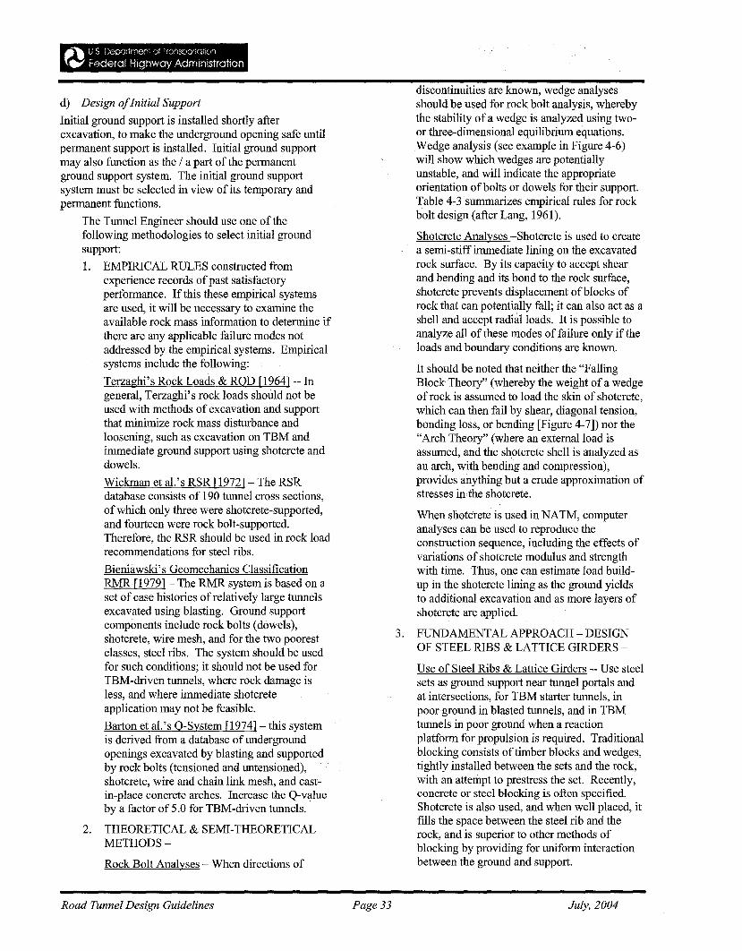
d) Design ofInitial Support
Initial ground support is installed shortly afterexcavation, to make the underground opening safe untilpermanent support is installed. Initial ground supportmay also function as the / a part of the permanentground support system. The initial ground supportsystem must be selected in view of its temporary andpermanent functions.
The Tunnel Engineer should use one of thefollowing methodologies to select initial groundsupport:
1. EMPIRICAL RULES constructed fromexperience records ofpast satisfactoryperformance. If this these empirical systemsare used, it will be necessary to examine theavailable rock mass information to determine ifthere are any applicable failure modes notaddressed by the empirical systems. Empiricalsystems include the following:
Terzaghi's Rock Loads & ROD [1964] -- Ingeneral, Terzaghi's rock loads should not beused with methods of excavation and supportthat minimize rock mass disturbance andloosening, such as excavation on TBM andimmediate ground support using shotcrete anddowels.
Wickman et at's RSR [1972] - The RSRdatabase consists of 190 tunnel cross sections,of which only three were shotcrete-supported,and fourteen were rock bolt-supported.Therefore, the RSR should be used in rock loadrecommendations for steel ribs.
Bieniawski's Geomechanics ClassificationRMR[1979] - The RMR system is based on aset of case histories of relatively large tunnelsexcavated using blasting. Ground supportcomponents include rock bolts (dowels),shotcrete, wire mesh, and for the two poorestclasses, steel ribs. The system should be usedfor such conditions; it should not be used forTBM-driven tunnels, where rock damage isless, and where immediate shotcreteapplication may not be feasible.
Barton et al.'s O-System [1974] - this systemis derived from a database ofundergroundopenings excavated by blasting and supportedby rock bolts (tensioned and untensioned),shotcrete, wire and chain link mesh, and eastin-place concrete arches. Increase the Q-valueby a factor of 5.0 for TBM-driven tunnels.
2. THEORETICAL & SEMI-THEORETICALMETHODS-
Rock Bolt Analyses - When directions of
Road Tunnel Design Guidelines
discontinuities are known, wedge analysesshould be used for rock bolt analysis, wherebythe stability of a wedge is analyzed using twoor three-dimensional equilibrium equations.Wedge analysis (see example in Figure 4-6)will show which wedges are potentiallyunstable, and will indicate the appropriateorientation ofbolts or dowels for their support.Table 4-3 summarizes empirical rules for rockbolt design (after Lang, 1961).
Shotcrete Analyses -Shotcrete is used to createa semi-stiff immediate lining on the excavatedrock surface. By its capacity to accept shearand bending and its bond to the rock surface,shotcrete prevents displacement ofblocks ofrock that can potentially fall; it can also act as ashell and accept radial loads. It is possible toanalyze all of these modes of failure only if theloads and boundary conditions are known.
It should be noted that neither the "FallingBlock Theory" (whereby the weight of a wedgeof rock is assumed to load the skin of shotcrete,which can then fail by shear, diagonal tension,bonding loss, or bending [Figure 4-7]) nor the"Arch Theory" (where an extemalload isassumed, and the shotcrete shell is analyzed asan arch, with bending and compression),provides anything but a crude approximation ofstresses in the shotcrete.
When shotcrete is used in NATM, computeranalyses can be used to reproduce theconstruction sequence, including the effects ofvariations of shotcrete modulus and strengthwith time. Thus, one can estimate load buildup in the shotcrete lining as the ground yieldsto additional excavation and as more layers ofshotcrete are applied.
3. FUNDAMENTAL APPROACH - DESIGNOF STEEL RIBS & LATTICE GIRDERS-
Use of Steel Ribs & Lattice Girders -- Use steelsets as ground support near tunnel portals andat intersections, for TBM starter tunnels, inpoor ground in blasted tunnels, and in TBMtunnels in poor ground when a reactionplatform for propulsion is required. Traditionalblocking consists of timber blocks and wedges,tightly installed between the sets and the rock,with an attempt to prestress the set. Recently,concrete or steel blocking is often specified.Shotcrete is also used, and when well placed, itfills the space between the steel rib and therock, and is superior to other methods ofblocking by providing for uniform interactionbetween the ground and support.
Page 33 July, 2004
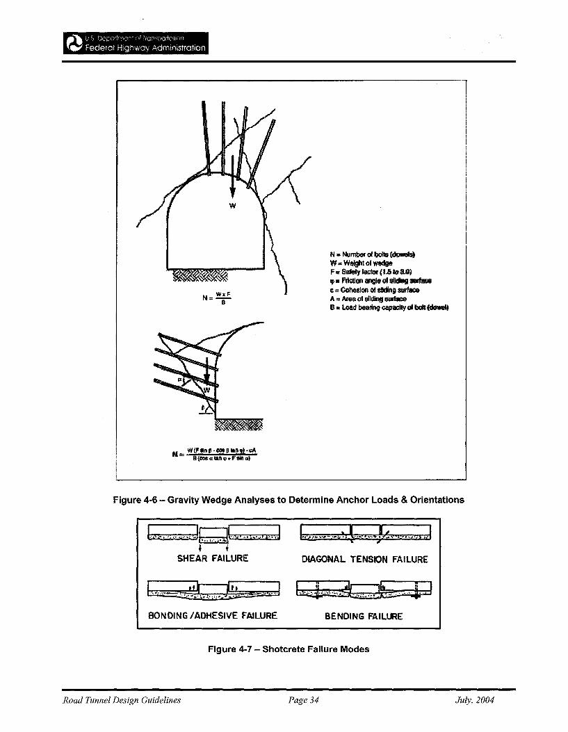
l'l. Number 01 bolls (dowels)W",W_oIW1Idg&F;; &IeIy Il!CIor jt.5 to3.0Jtp. Fdc1Ion qaot sll~ lIUffaeec.. CohMIOJI 01 siding surfaceA.. Area (II i!lIiding~B.. l.oacI beaftng~Glbolt(doweIt
N= WCFIlnI!-_~II!II.,H:'A
1I'(Cos ..1aJI q>" F1l1li ul
Figure 4-6 - Gravity Wedge Analyses to Determine Anchor Loads & Orientations
L,.: 'i" ...,.J~L1iI_";""i....1 b.·.·.~·.·jt~. ~!, .." ....• ...1~ t
SHEAR FAILURE DIAGONAL TENSION FAILURE
BONDING IADHESIVE FAILURE BENDING FAILURE
Figure 4-7 - Shotcrete Failure Modes
Road Tunnel Design Guidelines Page 34 July, 2004
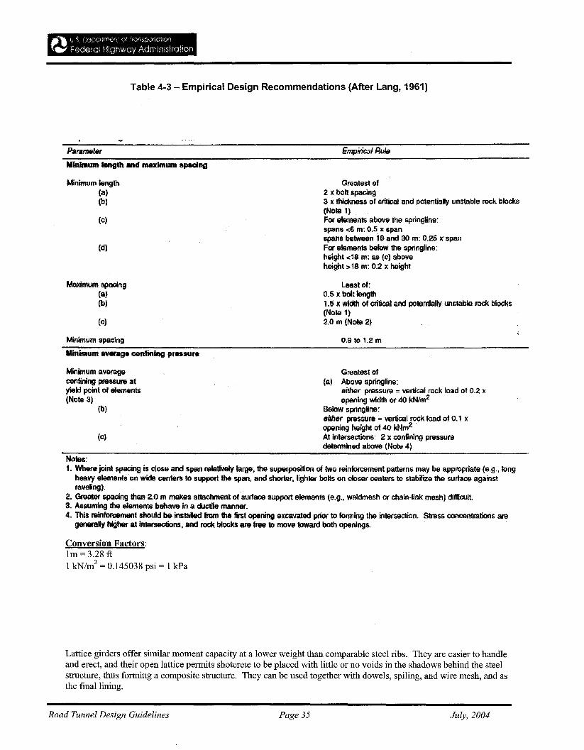
Table 4-3 - Empirical Design Recommendations (After Lang, 1961)
ParameterMinimum length and maximum spacing
Minimum length(a)(b)
(c)
(d)
Maximum spacing(a)(b)
(c)
Minimum spacing
Minimum lMM'age confining pressure
Minimum averageconfining pressure atyield point of elements(Note 3)
(b)
(0)
Empirical Rule
Greatest of2 x bolt spacing3x thickness of critical and potentially unstable rock blocks(NOle 1)For elements above the springline:spans <6 m: 0.5 x spanspans between 18 and 30 m: 0.25 )( spanFor elements below the springline:height <18 m: as (c) aboveheight>18 m: 0.2 x height
Least of:0.5 )( bolt length1.5 x width of critical and potentially unstable rock blocks(Note 1)2.0 m (Note 2)
0.9 to 1.2 m
Greatest of(a) Above springfine:
either pressure =vertical rock toad of 0.2 xopening width or 40 kNlm2
Below springline:either pressure =vertical rock load of 0.1 xopening height of 40 kNm2At intersections: 2 xconfining pressuredetermined above (Note 4)
Notes:1. Where joint spacing is close and span relatiVely large, the superposition of two reinforcement patterns may be appropriate (e.g., long
heavy elements on wide centers to support the span, and shorter, lighter bolts on closer centers to stabilize the surface againstraveling).
2. Greater spacing than 2.0 m makes attachment of sutface support elements (e.g., weldmesh or chain-fink mesh) difficult.3. Assuming the elements behave in a ciletile manner.4. This reintorC9l'l'lElnt should be installed from the first opening excavated prior to forming the intersection. Stress concentrations are
generally higher at intersections, and l'OCk blocks are free to move toward both openings.
Conversion Factors:Im= 3.28 ft1 kN/m2 = 0.145038 psi = 1 kPa
Lattice girders offer similar moment capacity at a lower weight than comparable steel ribs. They are easier to handleand erect, and their open lattice permits shotcrete to be placed with little or no voids in the shadows behind the steelstructure, thus forming a composite structure. They can be used together with dowels, spiling, and wire mesh, and asthe final lining.
Road Tunnel Design Guidelines Page 35 July, 2004
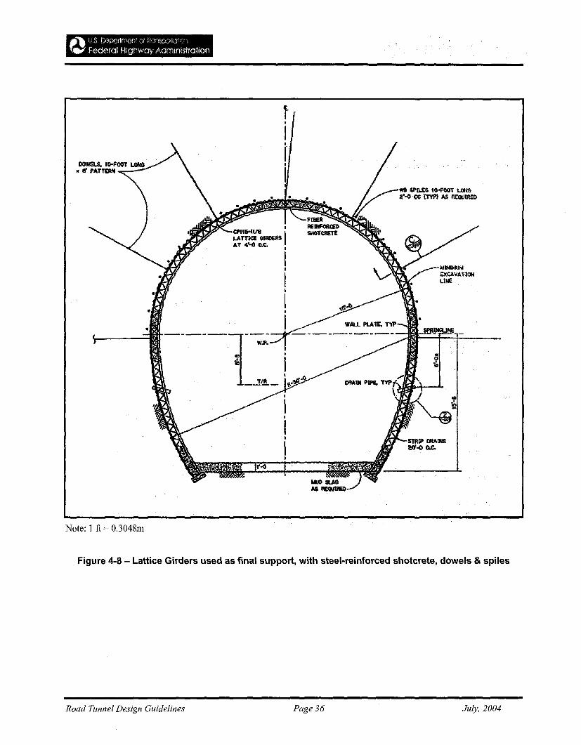
Note: 1 ft = 0.3048m
Figure 4-8 - Lattice Girders used as final support, with steel-reinforced shotcrete, dowels & spiles
Road Tunnel Design Guidelines Page 36 July, 2004
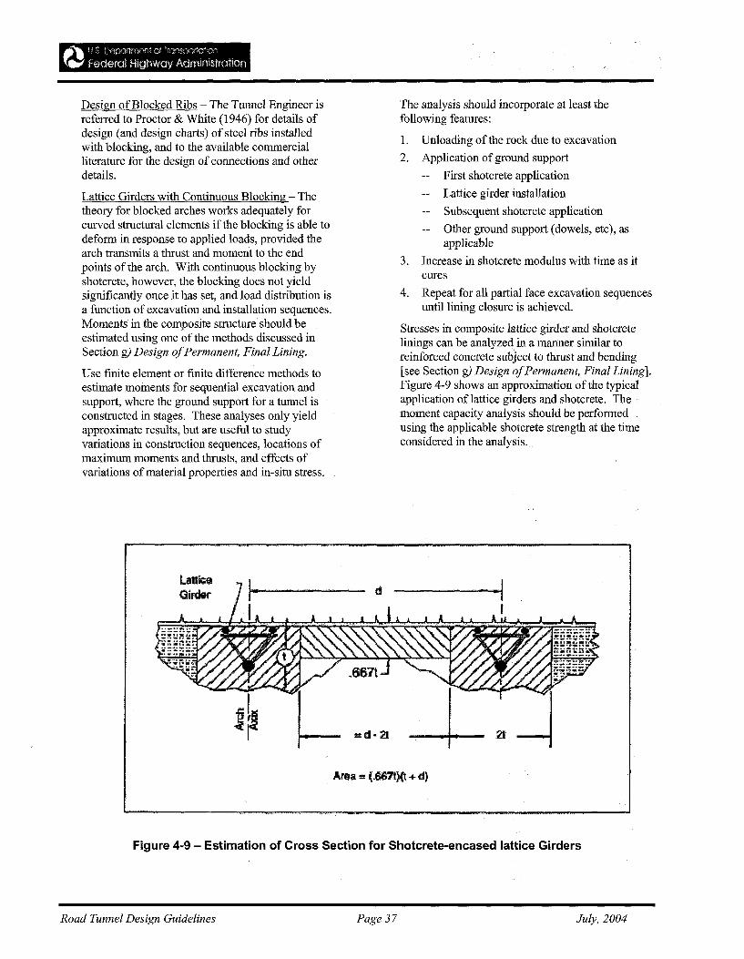
~~ c t; r:~m:M::;rtr~-w:~" e f rrO!lSD;)fiof!-i)n
r~, f&dera! HighWay Admimstration
Design of Blocked Ribs - The Tunnel Engineer isreferred to Proctor & White (1946) for details ofdesign (and design charts) of steel ribs installedwith blocking, and to the available commercialliterature for the design ofconnections and otherdetails.
Lattice Girders with Continuous Blocking - Thetheory for blocked arches works adequately forcurved structural elements if the blocking is able todeform in response to applied loads, provided thearch transmits a thrust and moment to the endpoints of the arch. With continuous blocking byshotcrete, however, the blocking does not yieldsignificantly once it has set, and load distribution isa function of excavation and installation sequences.Moments in the composite structure should beestimated using one of the methods discussed inSection g) Design ofPermanent, Final Lining.
Use finite element or finite difference methods toestimate moments for sequential excavation andsupport, where the ground support for a tunnel isconstructed in stages. These analyses only yieldapproximate results, but are useful to studyvariations in construction sequences, locations ofmaximum moments and thrusts, and effects ofvariations ofmaterial properties and in-situ stress.
L.ilIlI~a
·GitdrK
The analysis should incorporate at least thefollowing features:
1. Unloading of the rock due to excavation
2. Application ofground support
First shotcrete application
Lattice girder installation
Subsequent shotcrete application
Other ground support (dowels, etc), asapplicable
3. Increase in shotcrete modulus with time as itcures
4. Repeat for all partial face excavation sequencesuntil lining closure is achieved.
Stresses in composite lattice girder and shotcretelinings can be analyzed in a manner similar toreinforced concrete subject to thrust and bending[see Section g) Design ofPermanent, Final Lining].Figure 4-9 shows an approximation of the typicalapplication of lattice girders and shotcrete. Themoment capacity analysis should be performedusing the applicable shotcrete strength at the timeconsidered in the analysis.
Area == (.687f!}(t + d)
Figure 4-9 - Estimation of Cross Section for Shotcrete~encasedlattice Girders
Road Tunnel Design Guidelines Page 37 July, 2004
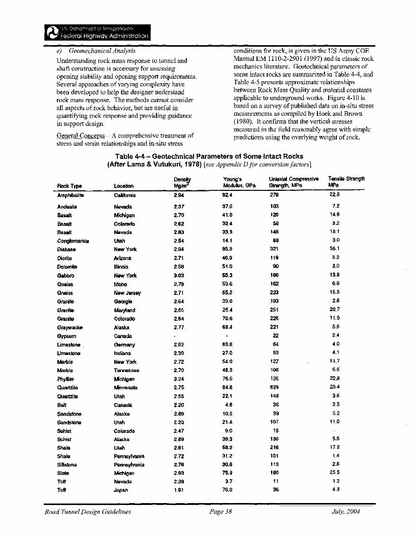
~~ t,:, Lt,,:t)(lrlf'!"\t:~~ '::/ ·f~.\f'l~,O;)'rGlt::tD
.... Federat Highway Admifvstratlon
e) Geomechanical Analysis
Understanding rock mass response to tunnel andshaft construction is necessary for assessingopening stability and opening support requirements.Several approaches of varying complexity havebeen developed to help the designer understandrock mass response. The methods cannot considerall aspects ofrock behavior, but are useful inquantifying rock response and providing guidancein support design.
General Concepts - A comprehensive treatment ofstress and strain relationships and in-situ stress
conditions for rock, is given in the US Army COEManual EM 1110-2-2901 (1997) and in classic rockmechanics literature. Geotechnical parameters ofsome intact rocks are summarized in Table 4-4, andTable 4-5 presents approximate relationshipsbetween Rock Mass Quality and material constantsapplicable to underground works. Figure 4-10 isbased on a survey ofpublished data on in-situ stressmeasurements as compiled by Hoek and Brown(1980). It confirms that the vertical stressesmeasured in the field reasonably agree with simplepredictions using the overlying weight of rock.
Table 4-4 - Geotechnical Parameters of Some Intact Rocks(After Lama & Vutukuri, 1978) [see Appendix D for conversion factors]
Dens, Young's Uniaxial CompressiVe Tensile StrengthRock Type Location MgIn1 Modulus, GPa Strength, MPs MPa
Amphibolite California 2.94 92.4 278 22.8
Andesillil Nevada 2.37 37.0 103 7.2
Basalt Michigan 2.70 41.0 120 14.6
Basalt Colorado 2.62 32.4 58 3.2
Basalt Navada 2.83 33.9 148 18.1
ConglGmerallil Ulah 2.54 14.1 88 3.0
Diabase HawVor!< 2.94 95.8 321 55.1
Diorite Arizona 2.71 46.9 119 8.2
Dolomite Illinois 2.58 51.0 90 3.0
Gabbro NewYoti< 3.03 55.3 186 13.8
Gneiss Idaho 2.79 53.6 162 6.9
Gneiss New Jersey 2.71 55.2 223 15.5
Granite Georgia 2.64 39.0 193 2.13
Granite Mal)'land 2.65 25.4 251 20.7
Granite Colorado 2.64 71).6 226 11.9
Graywacke Alaska 2.n 68.4 221 5.5
Gypsum canada 22 2.4
Umestone Germany 2.62 63.8 64 4.0
Umestone Indiana 2.30 27.0 53 4.1
Marble New York 2.72 54,0 127 11.7
Marble Tennessee 2.70 48.3 106 6.5
Phyllite Michigan 3.24 76.5 126 22.8
Quartzite MinNlsota 2.75 84.8 629 23.4
Quarttit8 Utah 2.55 22.1 148 3.5
Salt Canada 2.20 4.6 36 2.5
Sandstone Alaska 2.89 10.5 39 5.2
Sand$1one Utah 2.20 21.4 107 11.0
Schist Colorado 2.47 9.0 15
Schist Alaska 2.89 39.3 130 5.5
Shale Ulah 2.81 58.2 216 17.2
Shale Pennsylvania 2.12 31.2 101 1.4
SihGlone Pennsylvania 2.76 30.6 113 2.8
Slate Michigan :t93 75.9 180 25.5
Tuff Nevada 2.39 3.7 11 1.2
Tuff Japan 1.91 76.0 36 4.3
Road Tunnel Design Guidelines Page 38 July, 2004
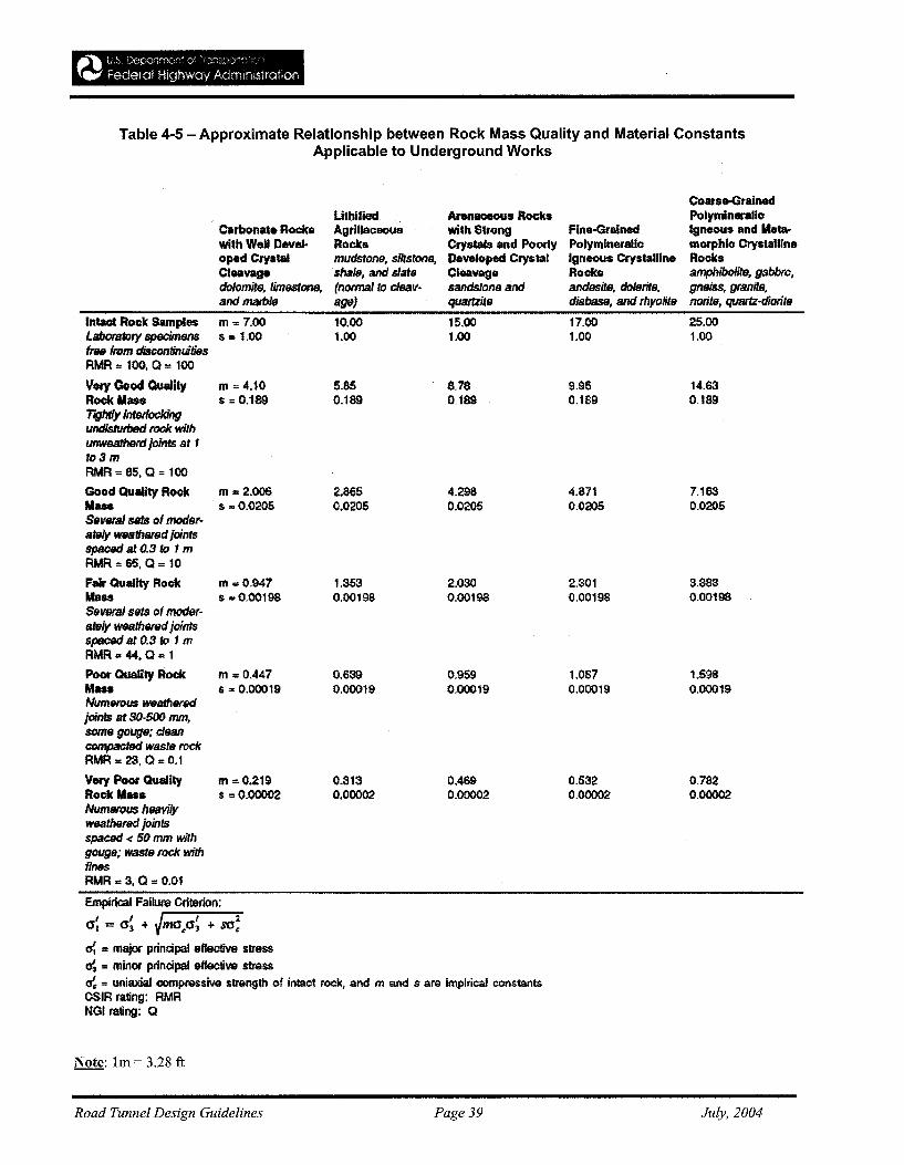
Table 4-5 - Approximate Relationship between Rock Mass Quality and Material ConstantsApplicable to Underground Works
Coarse-GralnedLithified Arenaceous Rocks Polymineralic
Carbonate Rocks Agtillaoeous with Strong Fine-Grained Igneous and U....with Well Dave). Rocks Cryscala and Poorly Polymineralic morphic Crystallineoped Crystal mudstone, siltstone, Developed Crystal Igneous Crystalline RocksCleavage shale, and slate Cleavage Rocks amphibolite, gabbro,dolomite, lim9StOll8, (normal to clflav- sandstone and andesite, dolerite, gnei$s. granite,and marble age) quartzite diabase, and rhyolite notite, quartz-diorite
In1actRock Samples m .. 7.00 10.00 15.00 17.00 25.00Laboratory specimens s = 1.00 1.00 1.00 1.00 1.00free from discontinuitiesRMR = 100,0 = 100
Very Cood Quality m .. 4.10 5.85 8.78 9.95 14.63Rock Mass s = 0.189 0.189 0.189 0.189 0.189Tightly interlockingundislUtbed rock withunweatherd joints at fto3mRMR .. 85, Q .. 100
Good Quality Rock m = 2.006 2,865 4.298 4.871 7.163Uau s =0.0205 0.0205 0.0205 0.0205 0.0205Several sets ofmoder-ately wealh8f8dJointsspaced at 0.3 to 1 mRMR '" 65, 0 = 10
Fair Quality Rock m.. 0.947 1.353 2.030 2.301 3.383Uass s =0.00198 0.00198 0.00198 0.00198 0.00198Several sets of moder-ately weathered jointsspacsd at 0.3 to 1mRMR=44.Q= 1
Poor Quality Rock m=0.447 0.639 0.959 1.087 1.598Mau s .. 0.00019 0.00019 0.00019 0.00019 0.00019Numerous wealheredjoints at 30-500 mm.some gouge; deancompacted wast. rockRMR = 23, Q = 0.1
Very Poor Quality m=0.219 0.313 0.469 0.532 0.782RockMass s =0.00002 0.00002 0.00002 0.00002 0.00002Numsrous heavilyweathered jointsspaced < 50 mm withgouge; wasts rock withfinesRMR = 3, 0 = 0.G1
Empirical Failure Criterion:
I I " I :I.0'1 = 0'3 + mac0'3 + roc~ = major principal effective stress~ = minor principal effective stresscT. =uniaxial compressive strength of intact rock, and m and s are impirical constantsCSIR rating: RMRNGI rating: Q
Note: 1m = 3.28 ft
Road Tunnel Design Guidelines Page 39 July, 2004
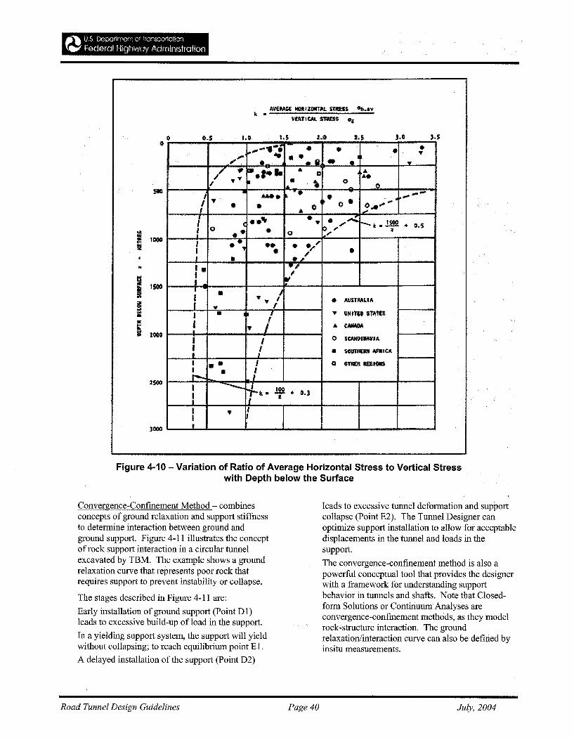
-"'\1} S C",p(]rtrr~)ft' (:! tronsp,mt"::n~..... fooera! HlghlNay Mministratjoo
-..... • • • •~.... ... ...,.' • • ... lit • l• • ..;/ 'fI ..... .. • ,
CI ...., ... " ~ • \. 00
I ....... ~ • • -- ...~,. • ~-I 0 o "... ....• • Cl .......; • • '9 • " ., .....r-t .1!!( • CI.S, 0 •• • 0
~ ... <!....I .., •• • ....,I • .. i' •,I •f •
.,: iIf'I • If
'II' • AtlSTMI.IA'II'... IJ • !
, .,. IlNI'riD s:T'A1U
i T l ... ~I I I) U'Ml)llMVIA
! ! • 1iOlmllM ""'ltA ,
I • • I CI ~ncl\ 1\(1'iI(IIl$I • /. .-.I ---~k. .!!& .- I).)
I :J
I ., ,It
oI)
~
i 1000
....~ 15llOI~III.,It:s 2000
(15 I" 2.0
Figure 4-10 - Variation of Ratio of Average Horizontal Stress to Vertical Stresswith Depth below the Surface
Convergence-Confinement Method - combinesconcepts ofground relaxation and support stiffuessto determine interaction between ground andground support. Figure 4-11 illustrates the conceptof rock support interaction in a circular tunnelexcavated by TBM. The example shows a groundrelaxation curve that represents poor rock thatrequires support to prevent instability or collapse.
The stages described in Figure 4-11 are:
Early installation ofground support (Point D1)leads to excessive build-up of load in the support.
In a yielding support system, the support will yieldwithout collapsing; to reach equilibrium point E1.
A delayed installation of the support (Point D2)
Road Tunnel Design Guidelines Page 40
leads to excessive tunnel deformation and supportcollapse (Point E2). The Tunnel Designer canoptimize support installation to allow for acceptabledisplacements in the tunnel and loads in thesupport.
The convergence-confinement method is also apowerful conceptual tool that provides the designerwith a framework for understanding supportbehavior in tunnels and shafts. Note that Closedform Solutions or ContinuumAnalyses areconvergence-confinement methods, as they modelrock-structure interaction. The groundrelaxation/interaction curve can also be defined byinsitu measurements.
July, 2004
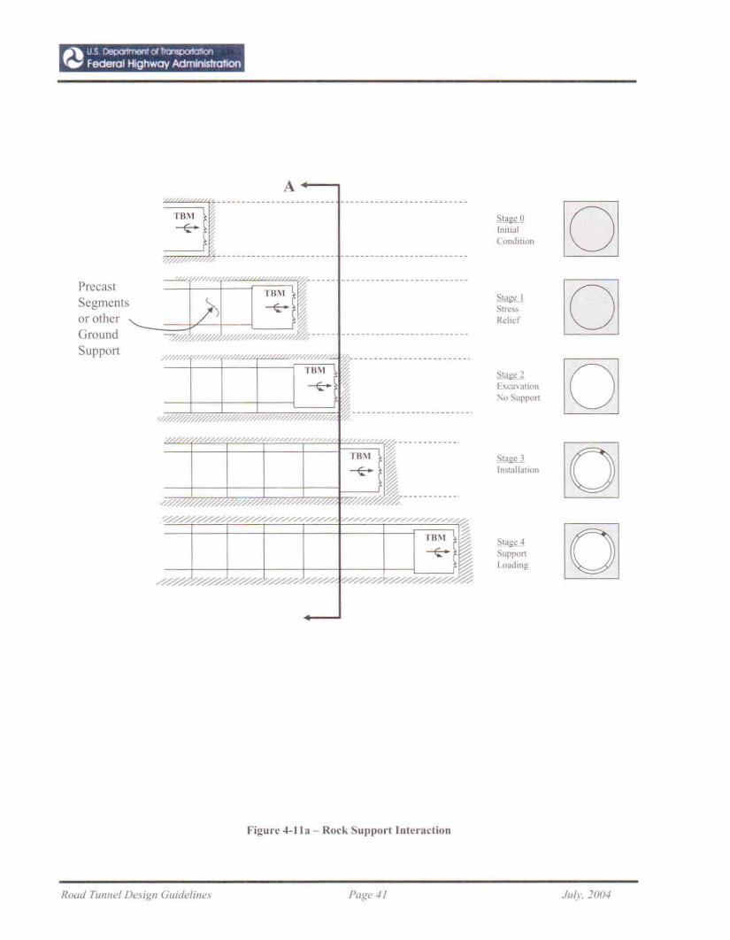
PrecastSegmentsor otherGroundSuppon
A~~~~~~~~~~~~~~~~~~~ ----_._-------------------
~. "... ~~~~ .. ~~~~~~.~~.~~~~~ --------------------------
-----.J ,. , ----- --------------------------TBJ\I ~}> ~ ~
~M h/ all,-···· ---------.-----_.---------
, ///, " 1'/./.1,; , w.... I///L ~._......._..........._.. "
TIJ\I ~~ ~
~
"Mr" @~w '~////// ' 'lW' ''//h/,/.----------------------_ ..
"'''"", v///////////////~·~///h,."., "" .",.. ~, , ~..........._.1'8\1 ~~~
~~
>0"~##/////////////////h~I//#~~·_----_·_---
~~.///.........///./........///.....................-/........................................................ "'"''''''''""fl~§§
~V///A.y///.4' :--/.Y//AV/////////A~
Figure 4-lla - Rock Supporllnleraction
.s:IU~ [0]1I11U:l1
(ondillon
Stage I [0]StressRehef
Slage 2- [0][xca\atlun'\0 Suppon
StaJtc.-l [QIn~lallallon
Sla1!C 4 [QSupponLoading
Road TUllnel Design Guideline.\' Page 41 JI/(I, 201M
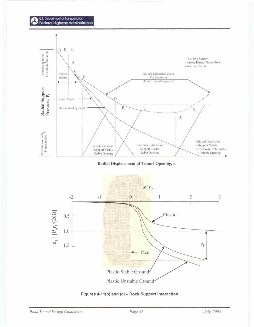
B
Ela)lIc:pla)lle:
,
cD,
•• Yielding Support-- Lincar Elastlc·Plastlc Rock-- No wne erreds
(iround Rel:l'I:al1on CUrl C
For Section A(PlastIc. un"tabk ground)
Delayed Installation- Support Y,cllh- EXCCS)I\C Deformation_. Un<;lablc Opemng
-- E,
D,
On·Time Installallon-- Suppon Elu)tu.:-- Swblc OpeJllng
.~.
~~~ _ .
Early Installation-- Support Yields- Slable Opemng
Pla:.l1c. Mable groutuJ,
Flastlc ~todl,.'
Radial Displacement of Tunnel Opening, It
xiI' I
-2 -I 0 2 3
~
""' Elastic0 0.5C'l'-'......"'0
0- 1.0~
......::;
1.5 rl
face
Plastic Stable Ground
Plastic Unstable Groun
Figures 4-11(b) and (c) - Rock Support Interaction
Road TUl1nel Design Guidelil1e'i Page 42 .h/~". 200-1
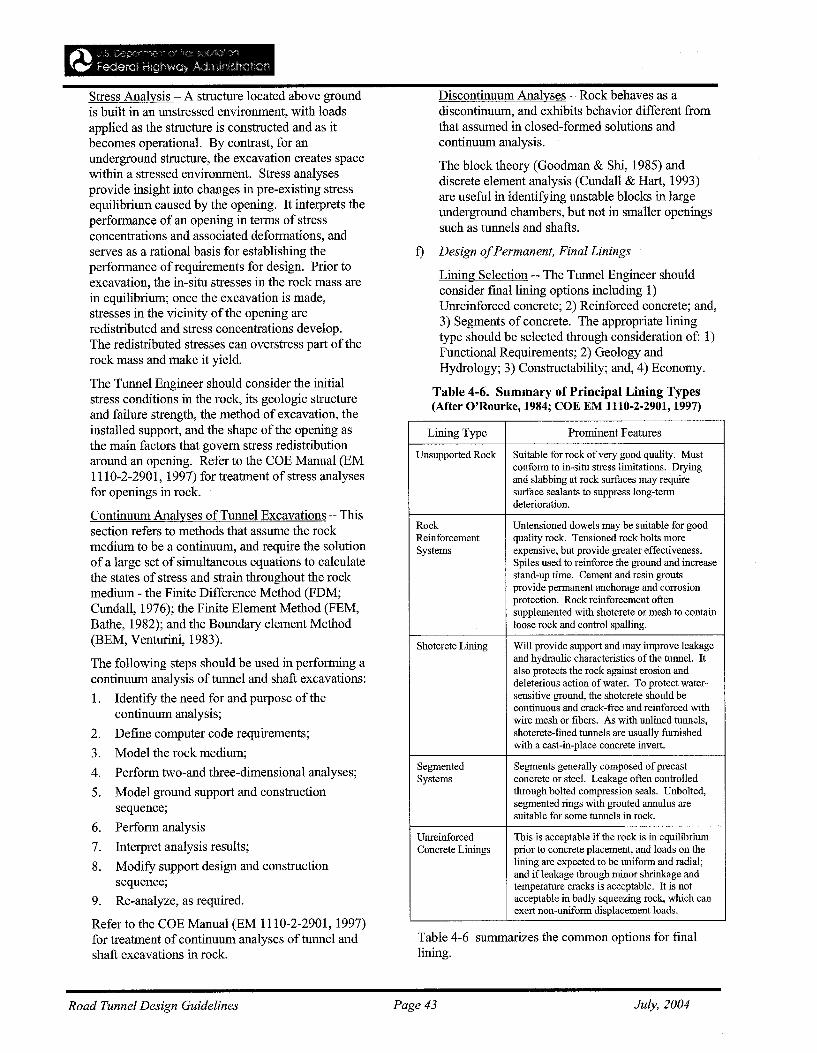
Stress Analysis - A structure located above groundis built in an unstressed environment, with loadsapplied as the structure is constructed and as itbecomes operational. By contrast, for anunderground structure, the excavation creates spacewithin a stressed environment. Stress analysesprovide insight into changes in pre-existing stressequilibrium caused by the opening. It interprets theperformance ofan opening in terms of stressconcentrations and associated deformations, andserves as a rational basis for establishing theperformance of requirements for design. Prior toexcavation, the in-situ stresses in the rock mass arein equilibrium; once the excavation is made,stresses in the vicinity of the opening areredistributed and stress concentrations develop.The redistributed stresses can overstress part of therock mass and make it yield.
The Tunnel Engineer should consider the initialstress conditions in the rock, its geologic structureand failure strength, the method of excavation, theinstalled support, and the shape of the opening asthe main factors that govern stress redistributionaround an opening. Refer to the COE Manual (EM1110-2-2901, 1997) for treatment of stress analysesfor openings in rock.
Continuum Analyses of Tunnel Excavations - Thissection refers to methods that assume the rockmedium to be a continuum, and require the solutionof a large set of simultaneous equations to calculatethe states of stress and strain throughout the rockmedium - the Finite Difference Method (FDM;Cundall, 1976); the Finite Element Method (FEM,Bathe, 1982); and the Boundary element Method(BEM, Venturini, 1983).
The following steps should be used in performing acontinuum analysis of tunnel and shaft excavations:
1. Identify the need for and purpose of thecontinuum analysis;
2. Define computer code requirements;
3. Model the rock medium;
4. Perform two-and three-dimensional analyses;
5. Model ground support and constructionsequence;
6. Perform analysis
7. Interpret analysis results;
8. Modify support design and constructionsequence;
9. Re-analyze, as required.
Refer to the COE Manual (EM 1110-2-2901, 1997)for treatment of continuum analyses of tunnel andshaft excavations in rock.
Discontinuum Analyses - Rock behaves as adiscontinuum, and exhibits behavior different fromthat assumed in closed-formed solutions andcontinuum analysis.
The block theory (Goodman & Shi, 1985) anddiscrete element analysis (Cundall & Hart, 1993)are useful in identifying unstable blocks in largeunderground chambers, but not in smaller openingssuch as tunnels and shafts.
t) Design ofPermanent, Final Linings
Lining Selection -- The Tunnel Engineer shouldconsider fmallining options including 1)Unreinforced concrete; 2) Reinforced concrete; and,3) Segments of concrete. The appropriate liningtype should be selected through consideration of: 1)Functional Requirements; 2) Geology andHydrology; 3) Constructability; and, 4) Economy.
Table 4-6. Summary of Principal Lining Types(After O'Rourke, 1984; COE EM 1110-2-2901, 1997)
Lining Type Prominent Features
Unsupported Rock Suitable for rock of very good quality. Mustconform to in-situ stress limitations. Dryingand slabbing at rock surfaces may requiresurface sealants to suppress long-termdeterioration.
Rock Untensioned dowels may be suitable for goodReinforcement quality rock. Tensioned rock bolts moreSystems expensive, but provide greater effectiveness.
Spiles used to reinforce the ground and increasestand-up time. Cement and resin groutsprovide permanent anchorage and corrosionprotection. Rock reinforcement oftensupplemented with shotcrete or mesh to containloose rock and control spalling.
Shotcrete Lining Will provide support and may improve leakageand hydraulic characteristics of the tunnel. Italso protects the rock against erosion anddeleterious action of water. To protect water-sensitive ground, the shotcrete should becontinuous and crack-free and reinforced withwire mesh or fibers. As with unlined tunnels,shotcrete-lined tunnels are usually furnishedwith a cast-in-place concrete invert.
Segmented Segments generally composed ofprecastSystems concrete or steel. Leakage often controlled
through bolted compression seals. Unbolted,segmented rings with grouted aunulus aresuitable for some tunnels in rock.
Unreinforced This is acceptable if the rock is in equilibriumConcrete Linings prior to concrete placement, and loads on the
lining are expected to be uniform and radial;and ifleakage through minor shrinkage andtemperature cracks is acceptable. It is notacceptable in badly squeezing rock, which canexert non-uniform displacement loads.
Table 4-6 summarizes the common options for finallining.
Road Tunnel Design Guidelines Page 43 July, 2004
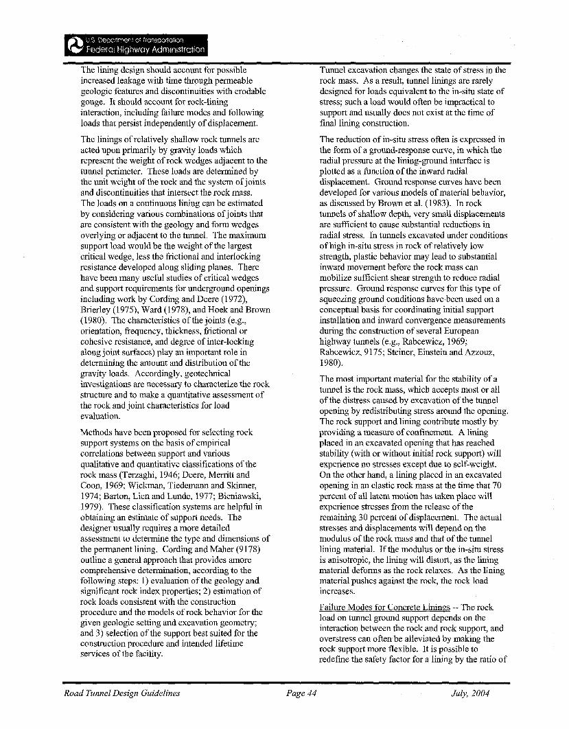
The lining design should account for possibleincreased leakage with time through permeablegeologic features and discontinuities with erodablegouge. It should account for rock-lininginteraction, including failure modes and followingloads that persist independently of displacement.
The linings ofrelatively shallow rock tunnels areacted upon primarily by gravity loads whichrepresent the weight of rock wedges adjacent to thetunnel perimeter. These loads are determined bythe unit weight of the rock and the system ofjointsand discontinuities that intersect the rock mass.The loads on a continuous lining can be estimatedby considering various combinations ofjoints thatare consistent with the geology and form wedgesoverlying or adjacent to the tunnel. The maximumsupport load would be the weight of the largestcritical wedge, less the frictional and interlockingresistance developed along sliding planes. Therehave been many useful studies of critical wedgesand support requirements for underground openingsincluding work by Cording and Deere (1972),Brierley (1975), Ward (1978), and Hoek and Brown(1980). The characteristics of the joints (e.g.,orientation, frequency, thickness, frictional orcohesive resistance, and degree of inter-lockingalong joint surfaces) play an important role indetermining the amount and distribution ofthegravity loads. Accordingly, geotechnicalinvestigations are necessary to characterize the rockstructure and to make a quantitative assessment ofthe rock and joint characteristics for loadevaluation.
Methods have been proposed for selecting rocksupport systems on the basis of empiricalcorrelations between support and variousqualitative and quantitative classifications of therock mass (Terzaghi, 1946; Deere, Merritt andCoon, 1969; Wickman, Tiedemann and Skinner,1974; Barton, Lien and Lunde, 1977; Bieniawski,1979). These classification systems are helpful inobtaining an estimate of support needs. Thedesigner usually requires a more detailedassessment to determine the type and dimensions ofthe permanent lining. Cording and Maher (9178)outline a general approach that provides amorecomprehensive determination, according to thefollowing steps: 1) evaluation ofthe geology andsignificant rock index properties; 2) estimation ofrock loads consistent with the constructionprocedure and the models of rock behavior for thegiven geologic setting and excavation geometry;and 3) selection of the support best suited for theconstruction procedure and intended lifetimeservices of the facility.
Road Tunnel Design Guidelines Page 44
Tunnel excavation changes the state of stress in therock mass. As a result, tunnel linings are rarelydesigned for loads equivalent to the in-situ state ofstress; such a load would often be impractical tosupport and usually does not exist at the time offinal lining construction.
The reduction of in-situ stress often is expressed inthe form of a ground-response curve, in which theradial pressure at the lining-ground interface isplotted as a function of the inward radialdisplacement. Ground response curves have beendeveloped for various models of material behavior,as discussed by Brown et al. (1983). In rocktunnels of shallow depth, very small displacementsare sufficient to cause substantial reductions inradial stress. In tunnels excavated under conditionsof high in-situ stress in rock ofrelatively lowstrength, plastic behavior may lead to substantialinward movement before the rock mass canmobilize sufficient shear strength to reduce radialpressure. Ground response curves for this type ofsqueezing ground conditions have been used on aconceptual basis for coordinating initial supportinstallation and inward convergence measurementsduring the construction of several Europeanhighway tunnels (e.g., Rabcewicz, 1969;Rabcewicz, 9175; Steiner, Einstein and Azzouz,1980).
The most important material for the stability ofatunnel is the rock mass, which accepts most or allof the distress caused by excavation of the tunnelopening by redistributing stress around the opening.The rock support and lining contribute mostly byproviding a measure of confinement. A liningplaced in an excavated opening that has reachedstability (with or without initial rock support) willexperience no stresses except due to self-weight.On the other hand, a lining placed in an excavatedopening in an elastic rock mass at the time that 70percent of all latent motion has taken place willexperience stresses from the release of theremaining 30 percent of displacement. The actualstresses and displacements will depend on themodulus of the rock mass and that of the tunnellining material. If the modulus or the in-situ stressis anisotropic, the lining will distort, as the liningmaterial deforms as the rock relaxes. As the liningmaterial pushes against the rock, the rock loadincreases.
Failure Modes for Concrete Linings -- The rockload on tunnel ground support depends on theinteraction between the rock and rock support, andoverstress can often be alleviated by making therock support more flexible. It is possible toredefine the safety factor for a lining by the ratio of
July, 2004
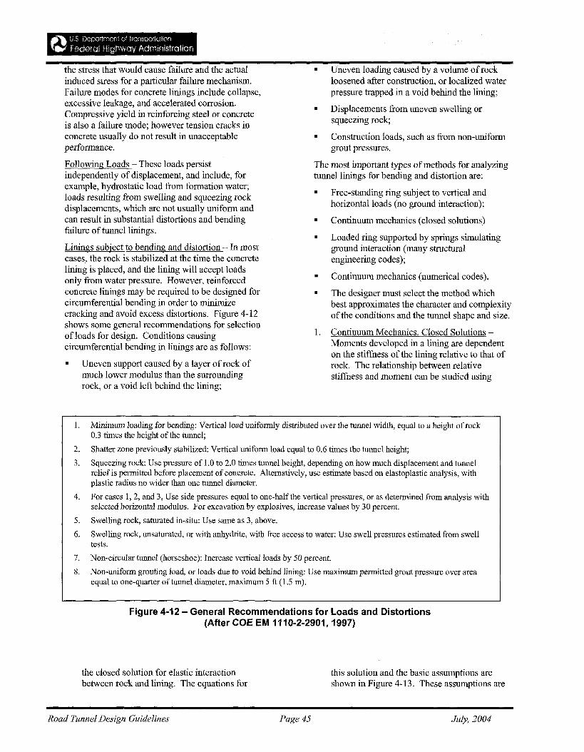
_'"'\ U,S [!e~,::lIirr,('''' 0' fr'J'Is:pCl1Gll")"
.~~ federal Hign'!'I"ay Admlntstration
the stress that would cause failure and the actualinduced stress for a particular failure mechanism.Failure modes for concrete linings include collapse,excessive leakage, and accelerated corrosion.Compressive yield in reinforcing steel or concreteis also a failure mode; however tension cracks inconcrete usually do not result in unacceptableperformance.
Following Loads - These loads persistindependently of displacement, and include, forexample, hydrostatic load from formation water;loads resulting from swelling and squeezing rockdisplacements, which are not usually uniform andcan result in substantial distortions and bendingfailure of tunnel linings.
Linings subject to bending and distortion - In mostcases, the rock is stabilized at the time the concretelining is placed, and the lining will accept loadsonly from water pressure. However, reinforcedconcrete linings may be required to be designed forcircumferential bending in order to minimizecracking and avoid excess distortions. Figure 4-12shows some general recommendations for selectionofloads for design. Conditions causingcircumferential bending in linings are as follows:
• Uneven support caused by a layer ofrock ofmuch lower modulus than the surroundingrock, or a void left behind the lining;
• Uneven loading caused by a volume ofrockloosened after construction, or localized waterpressure trapped in a void behind the lining;
• Displacements from uneven swelling orsqueezing rock;
• Construction loads, such as from non-uniformgrout pressures.
The most important types of methods for analyzingtunnel linings for bending and distortion are:
• Free-standing ring subject to vertical andhorizontal loads (no ground interaction);
• Continuum mechanics (closed solutions)
• Loaded ring supported by springs simulatingground interaction (many structuralengineering codes);
• Continuum mechanics (numerical codes).
• The designer must select the method whichbest approximates the character and complexityof the conditions and the tunnel shape and size.
1. Continuum Mechanics, Closed Solutions Moments developed in a lining are dependenton the stiffness of the lining relative to that ofrock. The relationship between relativestiffness and moment can be studied using
1. Minimum loading for bending: Vertical load uniformly distributed over the tunnel width, equal to a height of rock0.3 times the height of the tunnel;
2. Shatter zone previously stabilized: Vertical uniform load equal to 0.6 times the tunnel height;
3. Squeezing rock: Use pressure of 1.0 to 2.0 times tunnel height, depending on how much displacement and tunnelrelief is permitted before placement of concrete. Alternatively, use estimate based on elastoplastic analysis, withplastic radius no wider than one tunnel diameter.
4. For cases 1,2, and 3, Use side pressures equal to one-halfthe vertical pressures, or as determined from analysis withselected horizontal modulus. For excavation by explosives, increase values by 30 percent.
5. Swelling rock, saturated in-situ: Use same as 3, above.
6. Swelling rock, unsaturated, or with anhydrite, with free access to water: Use swell pressures estimated from swelltests.
7. Non-circular tunnel (horseshoe): Increase vertical loads by 50 percent.
8. Non-uniform grouting load, or loads due to void behind lining: Use maximum permitted grout pressure over areaequal to one-quarter of tunnel diameter, maximum 5 ft (1.5 m).
Figure 4-12 - General Recommendations for Loads and Distortions(After COE EM 1110-2-2901, 1997)
the closed solution for elastic interactionbetween rock and lining. The equations for
Road Tunnel Design Guidelines Page 45
this solution and the basic assumptions areshown in Figure 4-13. These assumptions are
July, 2004

hardly ever met in real life, except when alining is installed immediately behind the
advancing face of a tunnel or shaft, beforeelastic stresses have reached a state ofplanestrain equilibrium. Nonetheless, the solution isuseful for examining the effects of variations inimportant parameters. Note that the maximummoment is controlled by the flexibility ratio.
Road Tunnel Design Guidelines Page 46
Analysis of Moments & Forces using FEMMoments and forces in circular and noncircular tunnel linings can be determined usingstructural FEM computer programs. Suchanalyses have the following advantages:
• Variable properties can be given to rock aswell as lining elements;
• Irregular boundaries and shapes can behandled;
• Incremental construction loads can beanalyzed, including, for example, loads frombackfill grouting;
July, 2004
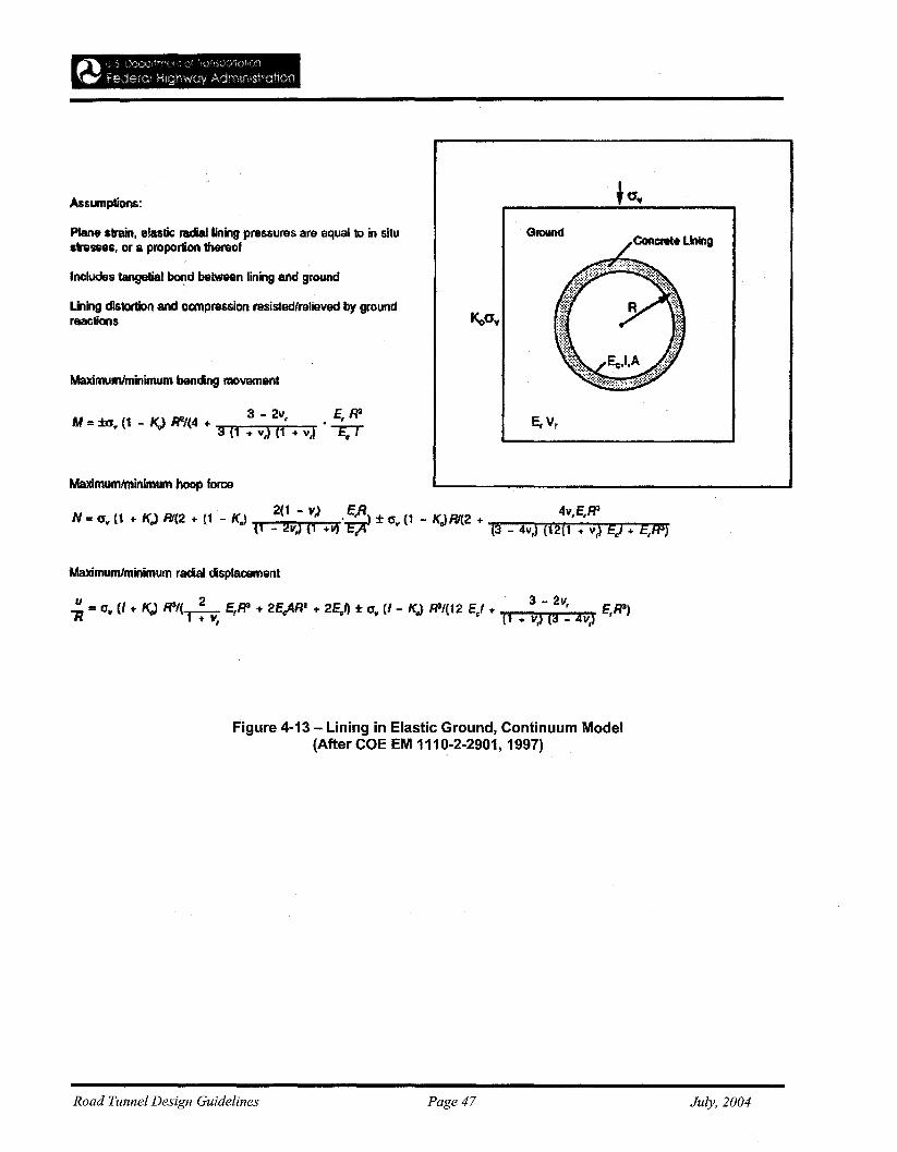
Assumptions:
Plane snin. elastic radial lining pressures are equal kI in sUustresses, or a proportion thereof
Includes tangelial bOfld between lining and ground
Liling cfl$tortion and ocmpression rasistedfrelieved by groundreactions
Maximumlminimum bending movement
AI : ±tY~ (1 _ KJ Ri/(4 + 3 - 2v, •~3 (1 ... vt) (1 ... vJ C c I
Maximumlminimum hoop force
N : or (1 ... KJ B'(2 + (1 - KJ 2(1 - 11,) VJ'i~) ± Gr
(1 - KJ Rf(2 + 4v,E,R'(1 - 211) (1 ... (3 _ av,) (12(1 ... v,) Ei ... EtRs)
Maximumhninimum radal displacement
u 2 3 - 211.... = err (l + KJ W/(.....---::- E,Ff3 .. 2E"ARz + 2EJI ± Or (1- K.,) RtJ(12 Ei .... 'E,FP)" I + V, (1 ... II,) (9 - 411)
Figure 4-13 - Lining in Elastic Ground, Continuum Model(After COE EM 1110·2·2901, 1997)
Road Tunnel Design Guidelines Page 47 July, 2004
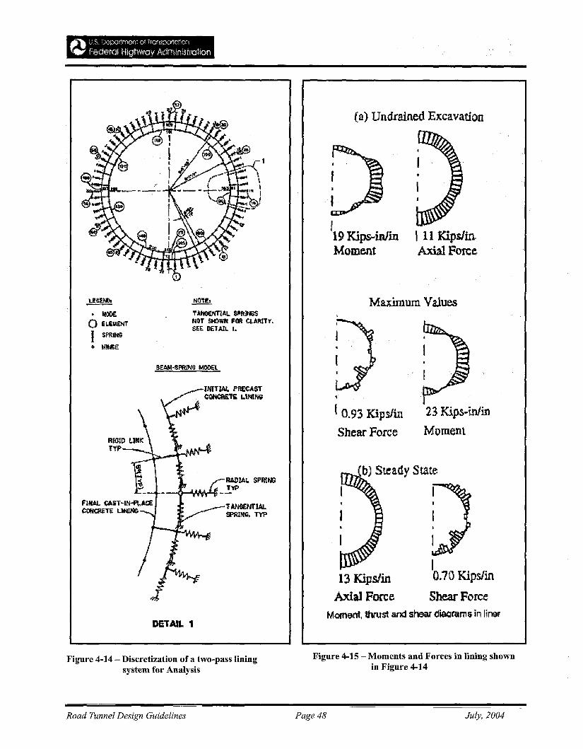
(a) Undrained Excavation
I 11 Kips/in.Axial Force
fI,I19 IGps-inlinMoment
23 Kips-inlin
Moment
Maximum V!lues
(bJ Steady State
II
I,
1
I0.70 Kips/in
Shear Force13 Kips/in
Axial Force
10.93 Kips/in
Shear Force
lAN~NT1AL
SPRING. TVP
NOTE,
T..utCC:NTIAL. sPat~hDT SI«)\lIN FCIfl 4AftlT '1'.SEE. DETAIL. I.
~
• tt:lO£o ELIM£NT
I SPRUtG
• 1oI1Nl:E
DETAIL 1Manent, thrust and shear disarama- in liner
Figure 4-14 - Discretization of a two-pass liningsystem for Analysis
Figure 4-15 - Moments and Forces in lining shownin Figure 4-14
Road Tunnel Design Guidelines Page 48 July, 2004
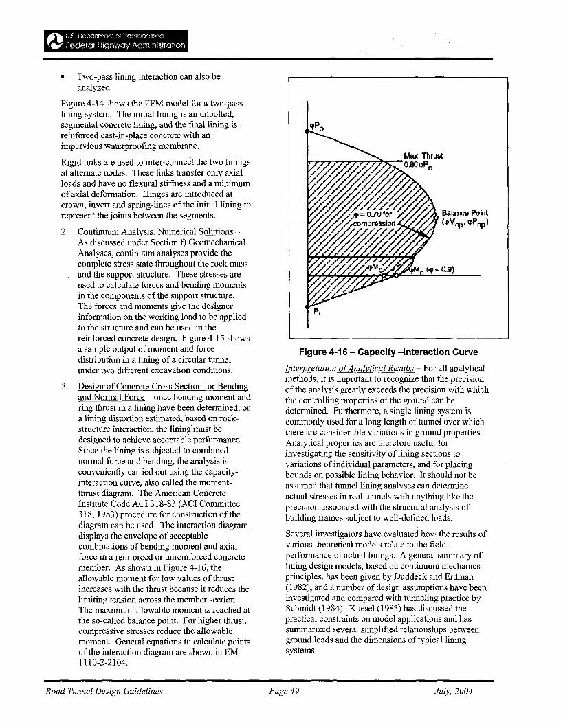
• Two-pass lining interaction can also beanalyzed.
Figure 4-14 shows the FEM model for a two-passlining system. The initial lining is an unbolted,segmental concrete lining, and the final lining isreinforced cast-in-place concrete with animpervious waterproofing membrane.
Rigid links are used to inter-connect the two liningsat alternate nodes. These links transfer only axialloads and have no flexural stiffness and a minimumof axial deformation. Hinges are introduced atcrown, invert and spring-lines ofthe initial lining torepresent the joints between the segments.
2. Continuum Analysis, Numerical Solutions As discussed under Section t) GeomechanicalAnalyses, continuum analyses provide thecomplete stress state throughout the rock massand the support structure. These stresses areused to calculate forces and bending momentsin the components of the support structure.The forces and moments give the designerinformation on the working load to be appliedto the structure and can be used in thereinforced concrete design. Figure 4-15 showsa sample output of moment and forcedistribution in a lining of a circular tunnelunder two different excavation conditions.
3. Design of Concrete Cross Section for Bendingand Normal Force ~ once bending moment andring thrust in a lining have been determined, ora lining distortion estimated, based on rockstructure interaction, the lining must bedesigned to achieve acceptable performance.Since the lining is subjected to combinednormal force and bending, the analysis isconveniently carried out using the capacityinteraction curve, also called the momentthrust diagram. The American ConcreteInstitute Code ACI 318-83 (ACI Committee318, 1983) procedure for construction of thediagram can be used. The interaction diagramdisplays the envelope of acceptablecombinations of bending moment and axialforce in a reinforced or unreinforced concretemember. As shown in Figure 4-16, theallowable moment for low values of thrustincreases with the thrust because it reduces thelimiting tension across the member section.The maximum allowable moment is reached atthe so-called balance point. For higher thrust,compressive stresses reduce the allowablemoment. General equations to calculate pointsof the interaction diagram are shown in EM1110-2-2104.
Balance Point(lpMop' cpPnp)
Figure 4-16 - Capacity -Interaction Curve
Interpretation ofAnalytical Results - For all analyticalmethods, it is important to recognize that the precisionof the analysis greatly exceeds the precision with whichthe controlling properties of the ground can bedetermined. Furthermore, a single lining system iscommonly used for a long length of tunnel over whichthere are considerable variations in ground properties.Analytical properties are therefore useful forinvestigating the sensitivity of lining sections tovariations of individual parameters, and for placingbounds on possible lining behavior. It should not beassumed that tunnel lining analyses can determineactual stresses in real tunnels with anything like theprecision associated with the structural analysis ofbuilding frames subject to well-defmed loads.
Several investigators have evaluated how the results ofvarious theoretical models relate to the fieldperformance of actual linings. A general summary oflining design models, based on continuum mechanicsprinciples, has been given by Duddeck and Erdman(1982), and a number of design assumptions have beeninvestigated and compared with tunneling practice bySchmidt (1984). Kuese1 (1983) has discussed thepractical constraints on model applications and hassummarized several simplified relationships betweenground loads and the dimensions of typical liningsystems
Road Tunnel Design Guidelines Page 49 July, 2004
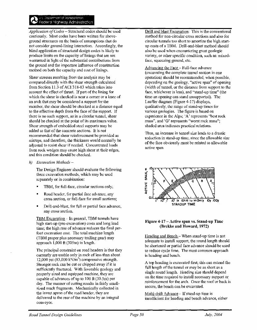
Application ofCodes - Structural codes should be usedcautiously. Most codes have been written for aboveground structures on the basis of assumptions that donot consider ground-lining interaction. Accordingly, theblind application of structural design codes is likely toproduce limits on the capacity of linings that are notwarranted in light of the substantial contributions fromthe ground and the important influence of constructionmethod on both the capacity and cost of linings.
Shear stresses resulting from the analysis may becompared directly with the shear strength calculatedfrom Section 11.3 of ACI 318-83 which takes· intoaccount the effect of thrust. If part of the lining forwhich the shear is checked is near a comer or a knee ofan arch that may be considered a support for themember, the shear should be checked at a distance equalto the effective depth from the face of the support. Ifthere is no such support, as in a circular tunnel, shearshould be checked at the point of its maximum value.Shear strength of embedded steel supports may beadded to that of the concrete sections. It is notrecommended that shear reinforcement be provided asstirrups, and therefore, the thickness would normally beadjusted to resist shear if needed. Concentrated loadsfrom rock wedges may cause high shear at their edges,and this condition should be checked.
h) Excavation Methods -
The Design Engineer should evaluate the followingthree excavation methods, which may be usedseparately or in combination:
• TBM, for full-face, circular sections only;
• Road header, for partial face advance, anycross section, or full-face for small sections;
• Drill-and-blast, for full or partial face advance,any cross section.
TBM Excavation - In general, TBM tunnels havehigh start-up (pre-excavation) costs and long leadtime; the high rate of advance reduces the final perfoot excavation cost. The total machine length(TBM proper plus necessary trailing gear) mayapproach 1,000 ft (305m) in length.
The principal constraint on road headers is that theycurrently are usable only in rock ofless than about12,000 psi (83,000 kN/m2
) compressive strength.Stronger rock can be cut or chipped away if it issufficiently fractured. With favorable geology andproperly sized and equipped machine, they arecapable of advances of up to 100 ft (30.5m) perday. The manner of cutting results in fairly smallsized muck fragments. Mechanically collected inthe invert apron of the road header, they aredelivered to the rear of the machine by an integralconveyor.
Road Tunnel Design Guidelines Page 50
Drill and blast Excavation: This is the conventionalmethod for non-circular cross sections and also forcircular tunnels too short to amortize the high startup costs of a TBM. Drill-and-blast method shouldalso be used when encountering great geologicvariety, or other specific condition, such as: mixedface, squeezing ground, etc.
Advancing the Face - Full-face advance(excavating the complete tunnel section in oneoperation) should be recommended, when possible,depending on the geology, "active span" of opening(width of tunnel, or the distance from support to theface, whichever is less), and "stand-up time" (thetime an opening can stand unsupported). TheLauffer diagram (Figure 4-17) displays,qualitatively, the range of stand-up times forvarious geologies. The figure is based onexperience in the Alps; 'A' represents "best rockmass", and 'G' represents "worst rock mass";shaded area indicates practical relations.
Thus, an increase in tunnel size leads to a drasticreduction in stand-up time, since the allowable sizeof the face obviously must be related to allowableactive span
e IO~....-.--.........,.....,...<""""!"..,-.,.....--.~,....-r-~
Z~III
IlJ>tce
Figure 4-17 - Active span vs. Stand-up Time(Brekke and Howard, 1972)
Heading and Bench - When stand-up time is notadequate to install support, the round length shouldbe shortened or partial face advance should be usedto reduce cycle time. The most common approachis heading and bench.
A top heading is excavated first; this can extend thefull length of the tunnel or may be as short as asingle round length. Heading size should dependon the time required to install necessary support orreinforcement for the arch. Once the roof or back issecure, the bench can be excavated.
Multi-drift Advance - If stand-up time isinsufficient for heading and bench advance, either
July, 2004
because of the geology or large spans, the topheading should be divided into two or more drifts.Advantages to doing this include:
1. Increase in stand-up time from reduced span;
2. Decrease in mucking time from reducedvolume;
3. Reduction in time required to install support orreinforcement.
NATM - NATM was discussed earlier in Chapter4.4 - Soft Ground Tunneling. As discussed here, itis a multi-drift approach based on observationalprocedure for verifying adequacy of installedsupport. Best judgment and past experience werecombined to select an initial drift size andaccompanying stabilization system. Measurementswere made to determine if inward movements weredecreasing or if additional stabilization wasnecessary. Theory was developed gradually andmore difficult ground conditions were evaluated.
Shotcrete and rock bolts should be used; they areavailable, inexpensive, and can easily beaugmented when the initial array must bereinforced. Shotcrete can also be used totemporarily stabilize the face of each advance,when necessary.
Lattice girders are a frequent component ofNATM,and consist of three or four sizeable concretereinforcing bars arranged in triangular ortrapezoidal section, pre-bent to the shape of theexcavation periphery, and joined together into apre-fabricated unit with continuous small-diameterlattice bars. After erection, the girder is filled andencased in shotcrete, and becomes an integral partof the initial support membrane.
i) Effect ofExcavation Method on Design
Unless the specifics of a tunnel clearly indicate thesuperiority of one excavation method over theother, the contract documents should leave thechoice to the contractor.
However, the Tunnel Designer should consider andanticipate the following
• Use of different stabilization patterns for a TBMdrive than for drill-and-blast excavation (forexample, use of circular steel ribs throughout,rather than only where required by bad ground).
• Preclusion of shotcreting within 500 ft (152m) ofthe cutter head ofa TBM because the bulk of themachine inhibits access to the tunnel walls andshotcrete rebound would foul the TBM.
• Use of Pattern Bolting in rock ofhigh massstrength, where the TBM is usually advanced bythrusting outward laterally with gripper jacks toprovide the necessary resistance to the thrust ofthe TBM ram jacks.
• Excavation ofTBM tunnel full-length for thelargest diameter required (i.e., steel rib or similarsystem) when tunnels have both good and badreaches. The rib or similar system then must beused full length, unless the TBM tail skin is slottedto permit rock bolting, or is equipped with boththrust jack and gripper propulsion systems andtime is taken to change over from one system tothe other, when necessary.
Road Tunnel Design Guidelines Page 51 July, 2004
~"""l: 1) S D('oartrrj.c~r" ::'~ i rCtrrS;::1\)1atl')f"t
{~ Federal Hlgrlwav AclrnlrJlStratloo
4.6 Mixed-Face or Difficult Ground
The Tunnel Designer should consider factors related to:
a) Instability -- Can arise from lack of stand-up timein: non-cohesive sands and gravels (especiallybelow the water table) and weak cohesive soils withhigh water content, or in blocky and seamy rock;adverse orientation ofjoint and fracture planes; orthe effects of flowing water
b) Heavy Loading: -- For a tunnel driven at depth inweak rock, squeezing, popping or explosive failureof the rock mass may be experienced due to heavyloading. For combinations ofparallel andintersecting tunnels, loadings should be evaluatedcarefully by the Tunnel Designer.
c) Obstacles and Constraints - Special considerationshould be given to natural obstacles, such as:boulder beds, in association with running silt andcaverns in limestone. In urban areas, potentialconstraints include: abandoned foundations andpiles, support systems for buildings in use and forfuture development.
d) Physical Conditions - The designer should considerthe potential for noxious gases in areas affected byrecent tectonic activity or continuing geothermalactivity; rock of organic origin; elevatedtemperatures; and contaminated soil.
e) Mixed-Face Tunneling - This term should be takento refer to situations, such as:
• when the lower part ofthe working face is in rockwhile the upper part is in soil, or vice versa;
• hard rock ledges in a soft matrix;
• beds of hard rock alternating with soft,decomposed, or weathered rock; or
• non-cohesive granular soil above hard clay;
• boulders in a soft matrix; or hard nodular inclusionsin soft rock (flint beds in chalk, or garnet in schist).
Consideration should be given to the potential for waterflow into the tunnel once the mixed condition isexposed, increasing further destabilization potential.Groundwater control and adequate, continuous supportof the weak material should be used to stabilize thehazard. The best time to seal off groundwater is beforeit starts to flow into the tunnel; otherwise, a bulkheadshould be needed to stop it from within the tunnel.
j) Drill-and-Blast Tunneling -- In squeezing ground, acloser approximation to a circular tunnel shapeoffers improved stability and longer tunnel life overvariations to the horseshoe shape offered by thistraditional method.
The Tunnel designer should consider techniques againstexcessive ground loading on the tunnel, such as:
• concrete-filled drifts;
• steel supports, and;
• use ofyielding supports when ground conditionsmake it imperative to provide for greaterconvergence for stress relief; support systemprovides a relatively low initial support pressure,and permits almost uniform stress relief for the rockin a controlled manner, around the entire tunnelcircumference, while preventing the rock fromraveling (Figures 4-18 and 4-19).
Long-term support resistance should be increased byadding small amounts of shotcrete at the junctionbetween the side wall and the invert slab and in the roofarch, as illustrated in Figure 4-19. This additionalshotcrete should be applied at a distance from theworking face that will avoid interference with mainproduction operations.
g) TBM Tunneling in squeezing ground -- In faultcrossings, water inflow carrying sand and fine rocktend to jam the cutters; cutter head design shouldallow only limited projection ofthe cutters forwardof the cutter head, using a face shield ahead of thestructural support element. Design should permitchanging of worn cutters from within the tunnel,requiring no access in front of the cutter head.
A short shrinkable shield should be used on themachine, to prevent closure of the ground around thecutter head shield and consequent immobilization of theTBM from the load on the shield system being too highto permit the machine to advance.
It is practical to delay major support installation until ahigh percentage of the total strain has taken place andground loading has been reduced, to prevent immediateinstability from squeezing of the soft rock.
TBM Tunneling System: The Tunnel designer shouldnote that the following TBM components are affectedby the difference between tunneling in squeezing andnon-squeezing ground:
L Cutter head - while the cutter head design isselected on the basis of the ground to be penetrated,the gauge cutters should be designed to be changedfrom behind, and a lighter false face should beprovided so that the cutter disks protrude only ashort distance. However, in weak ground a closedface shield should be used.
ii. Propulsion - Limit the bearing pressure on thetunnel walls to prevent failure of the weak rock,even under light loads. Use of multiple gripperscovering most of the circumference should beconsidered; the grippers should be of limited lengthto minimize uneven bearing on the squeezing rockface.
Road Tunnel Design Guidelines Page 52 July, 2004
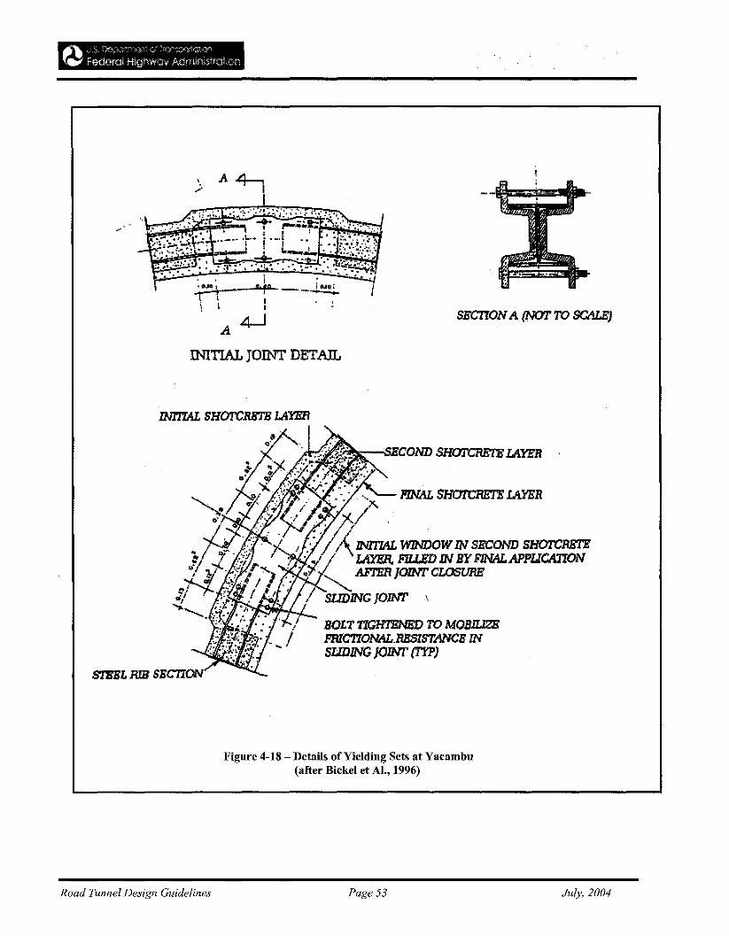
\ .A 4-..... . II
1 Ii~L g'1° - iOo.llf''T l . '''~.........-....
\' :,A4-J
OOTIAL JOINT DETAIL
SECTIONA (NOT TO SCALE)
S1EELRIBSEC770
Road Tunnel Design Guidelines
'~:-...;sEIr:OND SHOTCRET.B L4.1"FB
BOLTTlGHTENED TO MOBIlJZEFRlCT70NAL.RESISTANCE INSLIDING JOINT (TYP)
Figure 4-18 - Details of Yielding Sets at Yacambu(after Bickel et AI., 1996)
Page 53 July, 2004
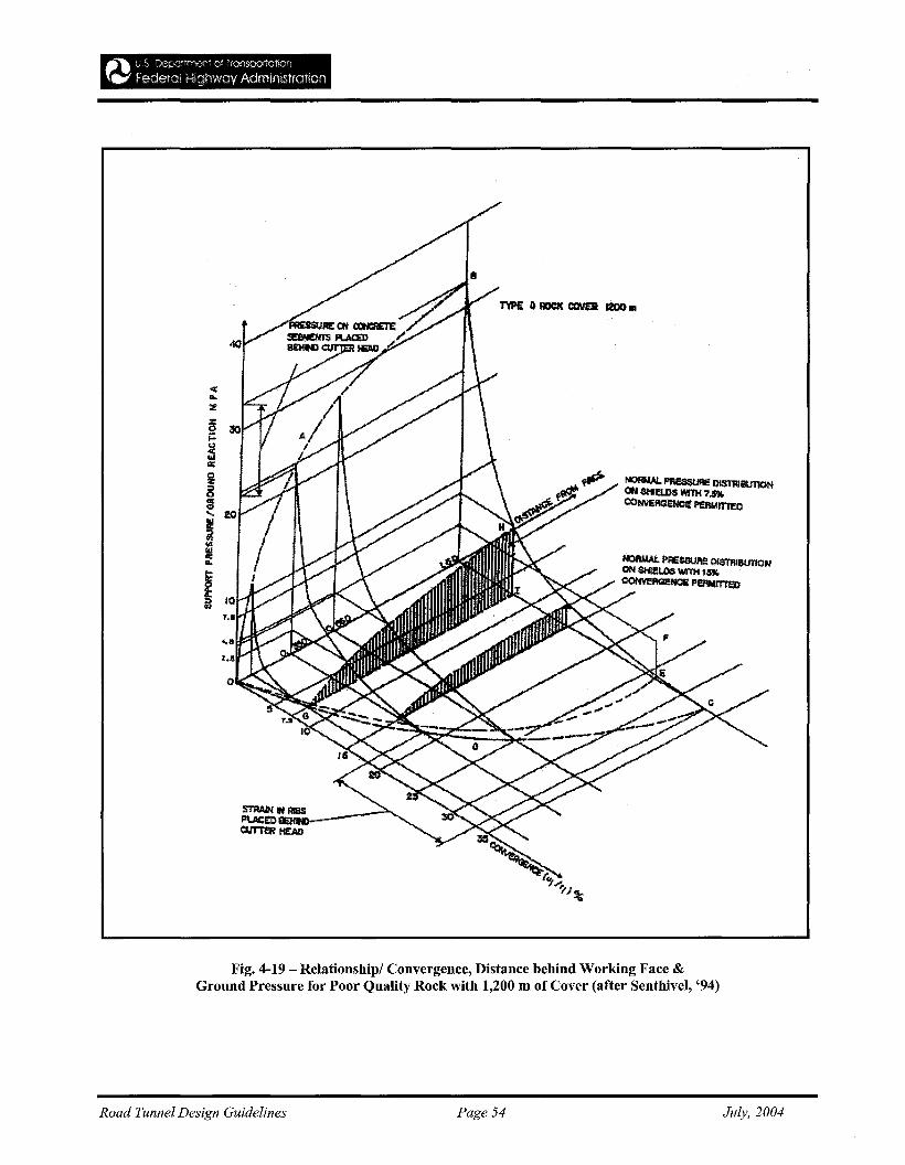
S'ilWH IN AISSPI.AC:£O EHNlQI.I'r1'!I'l' HEAD
Fig. 4-19 - Relationship/ Convergence, Distance behind Working Face &Ground Pressure for Poor Quality Rock with 1,200 m of Cover (after Senthivel, '94)
Road Tunnel Design Guidelines Page 54 July, 2004
Erector - The erector should be free to move along thetunnel, mounted on the conveyor truss, for completeflexibility in selecting the point at which ring erection isto take place.
Spoil Removal- conventional conveyor to rail carsystems, or single conveyor systems designed for thetunnel size selected, are appropriate.
Back-up System - any ancillary equipment should bekept clear of the area between the grippers and the ringerection area at track level.
4-7 Shafts
a) General --
Tunnels built through urban areas should consider usingshafts to reach the working area and to provide for muckremoval to minimize interference with existing services.Temporary tunnel shafts are used by the contractorduring construction while permanent shafts will becomean integral part of the tunnel structure.
b) Shaft Excavation in Soft Ground--
Installation Rate -- The rate of primary shaft lininginstallation should depend on the type of lining and thenature of the soil medium; installation every 4 or 5 ft(1.2 or 1.5 m) of advance is normal, albeit, shafts havebeen sunk up to 30 ft (9 m) without support.
Shaft Configuration -- Permanent shafts should beround, oval (NATM) or rectangular in shape and usuallywill have a final lining ofconcrete, which may be cast,either with forms on both sides or on the inside only,with the ground support system on the outside.
Shaft Support System -- The shaft support systemshould be designed to prevent plastic yielding duringshaft sinking in soft ground, and damage to existingstructures. The choice of sheeting and bracing systemshould be dictated by soil characteristics, shaft depth,diameter and economic factors, and should includeconsideration of: Timber Sheet Piling; Steel Sheet
Piling; Soldier Piles and Lagging; Liner Plates;Horizontal Ribs and Vertical Lining; Slurry Walls; anda NATM Shaft Support System (shown in Figure 4-20).
Excavation in Soft Wet Ground - Design of shaftexcavation in soft wet ground should evaluate: methodsoflowering the groundwater table; Open Pumping; useofa well point system, or deep wells; Soil Freezing; useof slurry; grouting; sinking a pneumatic caisson; andsinking a dredged drop caisson with a tremie concreteseal (Figures 4-21 and 4-22).
c) Shaft Excavation in Rock
Shaft excavation for tunnels are usually less than 120 ft(36.6 m) deep and, in rock, should be excavated by thedrill-and-blast method. The designer should refer tostandard Foundation Engineering texts for shaftconstruction in rock, and temporary and permanentwalls through weathered rock
Temporary Supports - In sedimentary, fractured orblocky rock, rock support should be placed quickly afterexcavation, when required. Evaluation of support typeshould include consideration of: Steel ribs and linerplates, steel ribs with lagging; rock bolts, with orwithout wire mesh; or shotcrete. Generally, all thevarious types of supports described earlier for support ofsoft ground shafts can be used (with some modification)in rock shafts.
d) Final Lining ofShafts -
The planned permanent usage of the shaft shoulddetermine the type of final lining; however, concrete orrock bolts and wire mesh/shotcrete lining should beconsidered.
e) The New Vertical Shield Tunnel -
This is a new system where a shield machine boresupward to excavate a vertical shaft from the shieldedtunnel with the primary lining.
The method has achieved successful results in reducingconstruction time and costs, enhancing work safety,minimizing public environmental hazard caused byconstruction noise, vibration, etc.
A synopsis of the method as used in excavating shaftson the Bandai-Hannan Trunk Sewer project is given byKonoha & Yamamoto (2002). Photo 4-7A shows a 7.5ft (228m) dia. EPB shield machine used for seweragetunnel in Japan.
Road Tunnel Design Guidelines Page 55 July, 2004
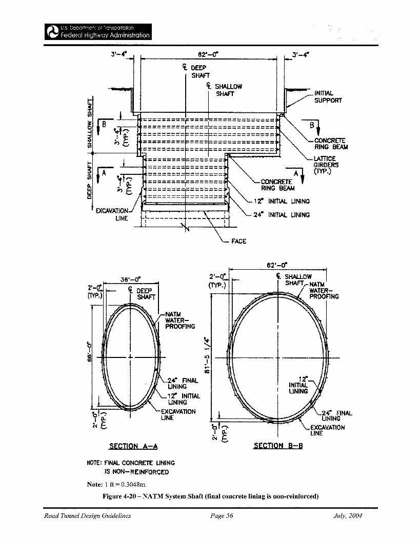
J'-4" 62'-0" 3'-4"
INITIALSUPPORT
~CONCRETERING BEAM
LAmeEGIRDERS(TYP.)
INITIAL UNING
INITIAL UNING
CONCRrn:Al
RING BEAM
ct. DEEPSHAFT
ct. SHAlLOWSHAFT
----_ ..-........... __ .... -.... .......
L _t
EXCAVATIONUNE
----_._--------i fA ..-r---~-K~~~~~~~-~ ~~o
82'-0"
SECTION A-A
<t. DEEPSHAFT
24'" FINALUNING
EXCAVATIONUNE
t SHAU.OWSHAFT NATM
WATERPROOFlNG
SECTION B-B
2'-(1'(TYP.)
NATMWATERPROOFlNG
24" FINAlUNING,2" INJTlAlUNING
EXCAVATIONUNE
36'-0"
NOTE: FINAL CONCRETE UNINGIS NON-REINFORCED
Note: 1 ft = O.3048m.
Figure 4-20 - NATM System Shaft (final concrete lining is non-reinforced)
Road Tunnel Design Guidelines Page 56 July, 2004

a)
i
n!lIi
b) AIRLINES
Figure 4-21- Schematic Representation of Dredged Caisson; a) Excavation by Clamshell, b) by Airlift.
Road Tunnel Design Guidelines Page 57 July, 2004
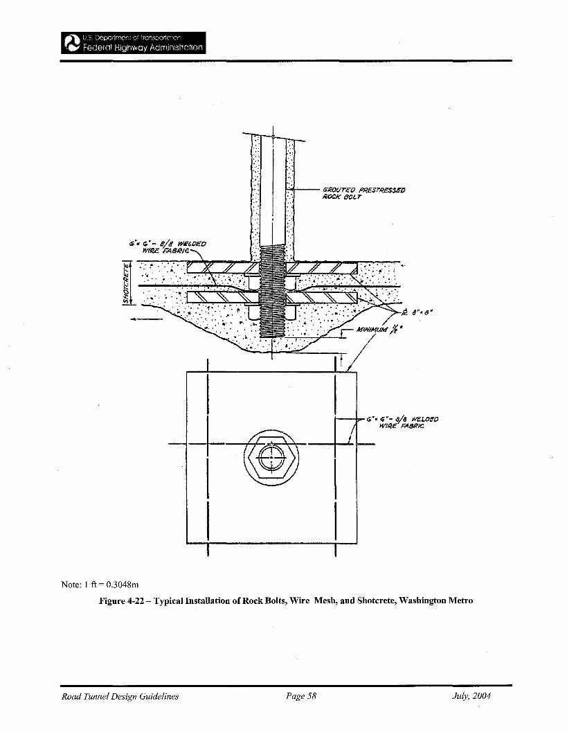
:;
;:
",-." .
.' :
'. "
""
I--~<:P'. ~'- ala we.I./)f!OWIR£ FABRIC
Note: 1 ft = O.3048m
Figure 4-22 - Typical Installation of Rock Bolts, Wire Mesh, and Shotcrete, Washington Metro
Road Tunnel Design Guidelines Page 58 July, 2004
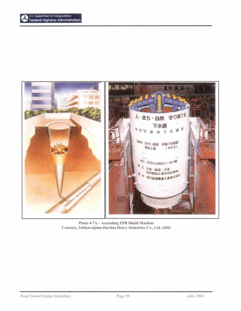
_", uS [)epa""",\! (J/ "<7>"""'''''''''~W federal Highway Administration
Photo ~-7A - Ascending EPR Shield I\JachineCourtes). Ishika\\ajima-Barima Bea,'y Industries Co., Ltd. (IBI)
Road TUflnel Design Guideline., Page 59 Ju/r. ]00./
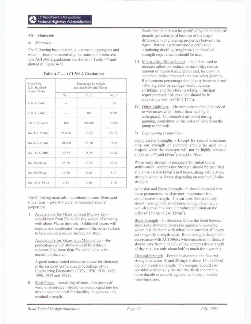
4-8 Shotcrete
oj Almerials-
The following basic materials -- cement. aggregates andwater -- should be essentially the same as for concrete.The ACI 506-2 gradations are shown in Table 4-7 andplotted in Figure 4-23.
Table ~-7·-ACI 506-2 Grad.tions
SIC\ C Size Percentage bj \\cighlu. . Standard passmg Indl\ idual Sie\ esSquare Mesh
No. I No.2 No.3
J/4111• (19 mill) -- 100
1''110. (12 mm) - 100 80-95
J RIn. (10 mm) 100 \/0-100 70-90
'\0.4 (4.75 mill) 95-100 70-.5 50-70
No.8 (2.4 mm) 80-100 50-70 35-55
No. J6{1.2 mill) 50-85 35-55 :W-lO
No. .10 (600 ~ I 25-60 20-35 10-.10
:"0. 50 (300 ~) 10-30 ·20 5-17
1\0.100(1 5°11) 2-10 1-10 2-10
The following materials accelerators, steel fibers andsilica fume - give shotcrete its necessary specialpropcl1ies:
I. Accelerators for Mixes withollt Micro silicashould vary from 2% 10 8% (by weighl of ccmenl).wilh aboUl 5% on Ihe arch. Addilional layers willrequire less accelerator because of lhe bener surfaceto be shot and lessened surface moisture.
AccelcraLOrs for Mixes with Micro silica -- thepercentages given above should be reducedsubstanlially: more Ihan 2% is unlikely to beneeded on the arch.
A good concentrated reference source lor shotcrcteis the series of conference proceedings oftheEngineering FoundaJion (1973. 1976_ 1978. 1982.1990. 1993 and 1995).
II. Sleel Fibers - consisling of shorl. Ihin pieces ofwire. or sheet steel. should be incorporated into themix to meet the need for ductility. toughness. andresidual strength.
teeI fiber should not bc specified by Ihe number ofpounds pcr cubic yard because of Ihe majordifference in engineering properties bct\\ccn thctypes. Rather, a performance specificationstipulating ductility (toughness) and residualstrength requirements should bl.': used.
III. Micro silica <Silica Fume) should be used toincrease adhesion. reduce permeability. reduceamount of required accelerator and. for dry-mix~hotcrcte. reduce rebound and dust when gunning.Replacemenl percentagc should \'ary belween 8 and13°0; a greater percentage would increase~hrillkage, and therefore. cracking. Principalrequirements for Micro silica should be inaccordancc wilh ASTM C 1240).
IV. Other Addilives - Air entrainment should be addedto wet mixes \\ hen freeze-thaw cycling isanticipated. Considerable air is lost duringgunning. sometimes on Ole order of 60% from thepump to Ihe \\all.
h) Engineering Properties
Compressive Strengths ~ Except for special siruations,only one strenglh of shotcrele should be used on aproject: when thc shotcrctc will not be highly stressed,4,000 psi (27,600 kN/m') should sumce.
When early strength is necessary for initial tunnelstabilizalion. compressive Strenglh should be specifiedal 700 psi (4.826 km') in 8 hours. along with a 3-dayslrength which will vary depending on required 28-dayslrength_
Adhesion and Shear Sirengih - II should be notcd Ihalthese parameters are of greater importance thancompressive strength. The surfaces shot are rarelysmooth enough that adhesion is acting alone: but. awell-designed mix should produce adhesiOli on theorder of 180 psi (1.2~1 k m').
Bond Strength - In shotcrete. this is the bond bemeensuccessivc shotcrcte layers (as opposed to concrete.where it is the bond wilh rebar) 10 ensure Ihal all layers.cl inlegrally strenglh-wise. Bond strengtb should be inaccordance with ACI 506R: \' hen measured in shear. itshould vary from 8 to 12% of the compressive strengthof dry mix. but only abollt half as mllch for a wet mix.
Flexural Strength For plain shotcrete. the flexuralstrength between 10 and 28 days is about 15 to 20% ofthe compressive strength. The designer should alsoconsider qualitalively Ihe facI Iha. fresh sholcrele IS
more ductile at an early age and will creep, therebyrelieving stress.
Road Tunnel Design Guidelines Page 60 Jill ... 2004
GRADINa CHART FaR SHDTCRIBT•. MIX••
•
It
•
...
'DO
•- .!'Bva..-'ZR-:.,U.II.8TeN~RD ~••l.& - ••U~A.~~~N'N=• ..-....
.~ ;.:.
oo~Ii•• IN ao"•••, :1 .I I I l. .......11i I i .r ! I j / II ; I
•[-AGGREGATE: i I t r : 1 !,..
GRADATION CIlIlVE I 1/ !l I I ,I
Rll\ ~1lE:rE I. X ". i I II / I j I ! i !, I 1 / l 1/ I ,I· i II 1_.
/ I j I II I I II I I I V y I i ! !
I t I !/ /! : ! ,II,
/' / I I I :..I I 1I,
I I V ./ : i I I I, I... " V I 17 I I I I iI
IZt it i I r 1 I ;I .' I
" V I /1 ! I I I II'JI ./1 I V ; 1 I I 1.. I i./ I I I f II
I ./ I /1 i I I : ! l•• -- I ........... T l i I 1 II
I 1--1 1 I l I I I I..1M •• •• .. ... to It 10 • • • ~ ~ '. • ........11I
a-..2at ...«~.....IIIUIIIIIII...~~
Fig. 4-23 Grading Chart for Shotcrete Mixes
Ductility - The ability to incur large defonnationwithout rupture is obtained by the use of fiberreinforcement. Flexural strength and residual strengthshould be specification items.
Impenneability - Greater impenneability should beobtained by:
• Avoiding excessively cement-rich mixes (tominimize shrinkage cracking);
• Using fiber (to minimize and distribute opening ofshrinkage cracks);
• Using more finely-ground cements;
• Adding silica fume;
• Careful control of nozzle distance and attitude(promotes maximum density in the in-placeconcrete).
c) Testing-
Shotcrete placed for the Contractor's convenienceshould be his sole responsibility and testing should notbe required by the designer. Shotcrete testing should bea three-part process, as follows:
1. Compatibility Testing - should be required beforeproposed materials and sources are approved.ASTM Cl102 should be followed with regards to
cement-accelerator compatibility. Proposed mixesshould be prepared, cured and tested in thelaboratory.
2, Field Trials - should follow upon completion ofcompatibility testing, and, after curing in themanner proposed for the production work, coresand beams should be taken and tested.
3. Production Testing - should be done in three parts:
• The field trial process should be repeated at theheading during production shotcreting, upondemand by the engineer;
• Cores should be taken from the in-place shotcrete,at specified intervals, to check thickness, adhesion,and compressive strength;
• Visual check and sounding at frequent intervals,with cores removed and tested at suspectlocations.
Special Tests - When a high degree ofimpenneability is required, the mix designeffectiveness should be tested according to ASTMC642 using a maximum boiling absorption value of6%.
Flexural toughness of fiber-impregnated shotcrete
Road Tunnel Design Guidelines Page 61 July, 2004
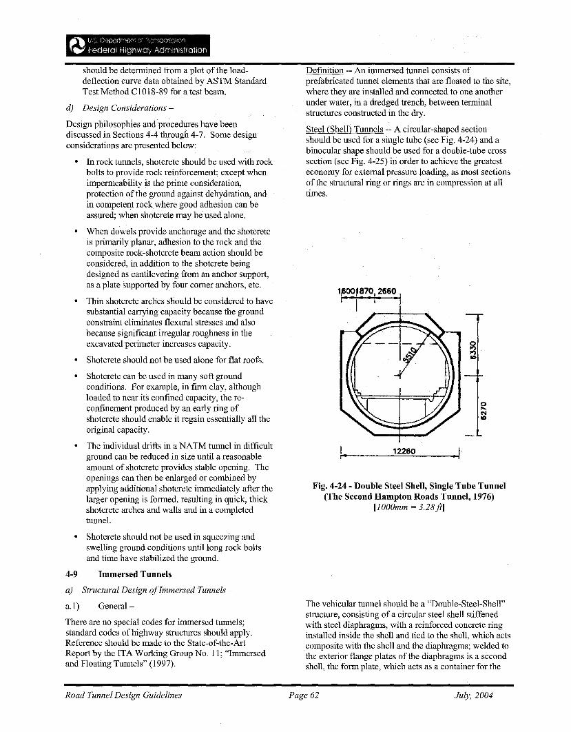
should be detennined from a plot of the loaddeflection curve data obtained by ASTM StandardTest Method C1018-89 for a test beam.
d) Design Considerations-
Design philosophies and procedures have beendiscussed in Sections 4-4 through 4-7. Some designconsiderations are presented below:
• In rock tunnels, shotcrete should be used with rockbolts to provide rock reinforcement; except whenimpenneability is the prime consideration,protection of the ground against dehydration, andin competent rock where good adhesion can beassured; when shotcrete may be used alone.
• When dowels provide anchorage and the shotcreteis primarily planar, adhesion to the rock and thecomposite rock-shotcrete beam action should beconsidered, in addition to the shotcrete beingdesigned as cantilevering from an anchor support,as a plate supported by four corner anchors, etc.
• Thin shotcrete arches should be considered to havesubstantial carrying capacity because the groundconstraint eliminates flexural stresses and alsobecause significant irregular roughness in theexcavated perimeter increases capacity.
• Shotcrete should not be used alone for flat roofs.
• Shotcrete can be used in many soft groundconditions. For example, in finn clay, althoughloaded to near its confined capacity, the reconfinement produced by an early ring ofshotcrete should enable it regain essentially all theoriginal capacity.
• The individual drifts in a NATM tunnel in difficultground can be reduced in size until a reasonableamount of shotcrete provides stable opening. Theopenings can then be enlarged or combined byapplying additional shotcrete immediately after thelarger opening is fonned, resulting in quick, thickshotcrete arches and walls and in a completedtunnel.
• Shotcrete should not be used in squeezing andswelling ground conditions until long rock boltsand time have stabilized the ground.
4-9 Immersed Tunnels
a) Structural Design ofImmersed Tunnels -
a.1) General -
There are no special codes for immersed tunnels;standard codes of highway structures should apply.Reference should be made to the State-of-the-ArtReport by the ITA Working Group No. 11; "Immersedand Floating Tunnels" (1997).
Defmition -- An immersed tunnel consists ofprefabricated tunnel elements that are floated to the site,where they are installed and connected to one anotherunder water, in a dredged trench, between tenninalstructures constructed in the dry.
Steel (Shell) Tunnels -- A circular-shaped sectionshould be used for a single tube (see Fig. 4-24) and abinocular shape should be used for a double-tube crosssection (see Fig. 4-25) in order to achieve the greatesteconomy for external pressure loading, as most sectionsof the structural ring or rings are in compression at alltimes.
gNo
1r-1.. -..:.::12=26=..:O::..-_--...J
Fig. 4-24 - Double Steel Shell, Single Tube Tunnel(The Second Hampton Roads Tunnel, 1976)
[lOOOmm = 3.28ft]
The vehicular tunnel should be a "Double-Steel-Shell"structure, consisting of a circular steel shell stiffenedwith steel diaphragms, with a reinforced concrete ringinstalled inside the shell and tied to the shell, which actscomposite with the shell and the diaphragms; welded tothe exterior flange plates of the diaphragms is a secondshell, the fonn plate, which acts as a container for the
Road Tunnel Design Guidelines Page 62 July, 2004
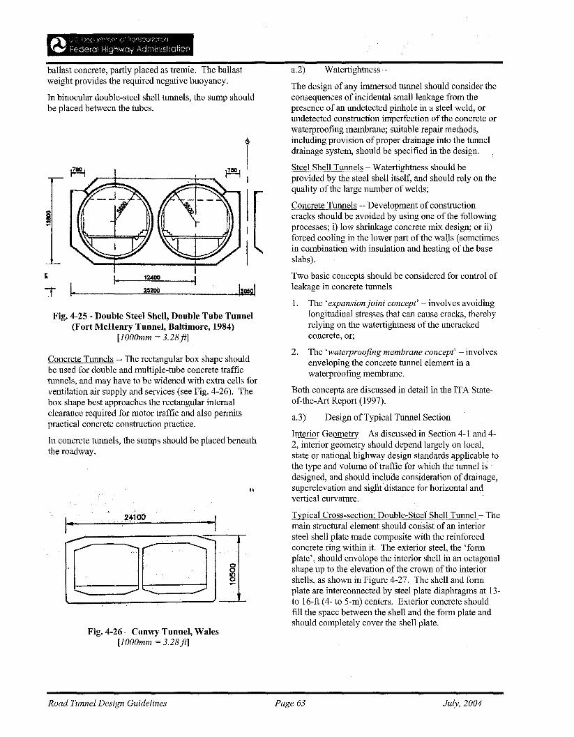
ballast concrete, partly placed as tremie. The ballastweight provides the required negative buoyancy.
In binocular double-steel shell tunnels, the sump shouldbe placed between the tubes.
i
I-r ~ --=252=OO~ _
Fig. 4-25 - Double Steel Shell, Double Tube Tunnel(Fort McHenry Tunnel, Baltimore, 1984)
[lOOOmm = 3.28ft]
Concrete Tunnels -- The rectangular box shape shouldbe used for double and multiple-tube concrete traffictunnels, and may have to be widened with extra cells forventilation air supply and services (see Fig. 4-26). Thebox shape best approaches the rectangular internalclearance required for motor traffic and also permitspractical concrete construction practice.
In concrete tunnels, the sumps should be placed beneaththe roadway.
I'
1..~__··~_·~1_00 ",·=-I_r
o:6o...
Fig. 4-26 - Conwy Tunnel, Wales[lOOOmm = 3.28ft]
a.2) Watertightness-
The design of any immersed tunnel should consider theconsequences of incidental small leakage from thepresence of an undetected pinhole in a steel weld, orundetected construction imperfection of the concrete orwaterproofing membrane; suitable repair methods,including provision ofproper drainage into the tunneldrainage system, should be specified in the design.
Steel Shell Tunnels - Watertightness should beprovided by the steel shell itself, and should rely on thequality of the large number of welds;
Concrete Tunnels -- Development of constructioncracks should be avoided by using one of the followingprocesses; i) low shrinkage concrete mix design; or ii)forced cooling in the lower part of the wa\ls (sometimesin combination with insulation and heating of the baseslabs).
Two basic concepts should be considered for control ofleakage in concrete tunnels -
1. The'expansion joint concept' - involves avoidinglongitudinal stresses that can cause cracks, therebyrelying on the watertightness of the uncrackedconcrete, or;
2. The 'waterproofing membrane concept' - involvesenveloping the concrete tunnel element in awaterproofing membrane.
Both concepts are discussed in detail in the ITA Stateof-the-Art Report (1997).
a.3) Design ofTypical Tunnel Section
Interior Geometry - As discussed in Section 4-1 and 42, interior geometry should depend largely on local,state or national highway design standards applicable tothe type and volume oftraffic for which the tunnel isdesigned, and should include consideration of drainage,superelevation and sigut distance for horizontal andvertical curvature.
Typical Cross-section; Double-Steel Shell Tunnel- Themain structural element should consist of an interiorsteel shell plate made composite with the reinforcedconcrete ring within it. The exterior steel, the 'formplate', should envelope the interior shell in an octagonalshape up to the elevation of the crown of the interiorshells, as shown in Figure 4-27. The shell and formplate are interconnected by steel plate diaphragms at 13to 16-ft (4- to 5-m) centers. Exterior concrete shouldfill the space between the shell and the form plate andshould completely cover the shell plate.
Road Tunnel Design Guidelines Page 63 July, 2004
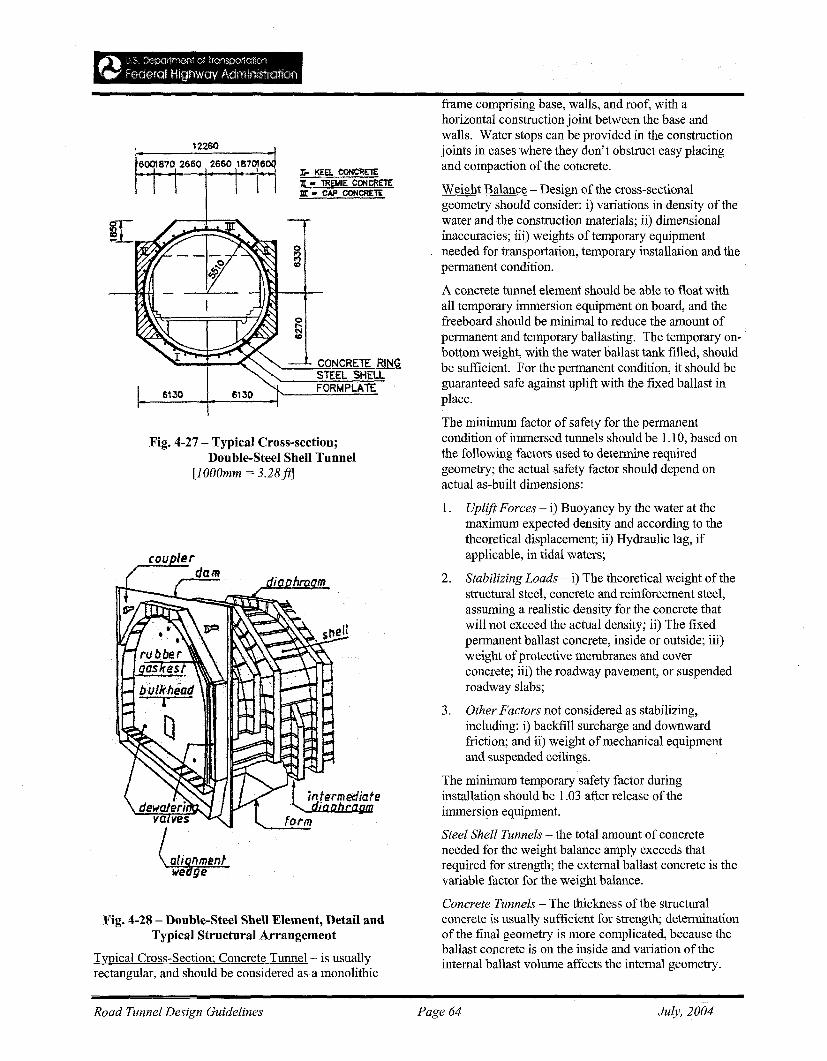
Fig. 4-27 - Typical Cross-section;Double-Steel Shell Tunnel
[lOOOmm = 3.28ft]
:Ii- KEa CONCRETEJI: - lREMIE CONCRETE:m: - CAP CONCRETE
CONCRElE RINGSTEEL SHELLFORMPLATE
frame comprising base, walls, and roof, with ahorizontal construction joint between the base andwalls. Water stops can be provided in the constructionjoints in cases where they don't obstruct easy placingand compaction of the concrete.
Weight Balance - Design of the cross-sectionalgeometry should consider: i) variations in density of thewater and the construction materials; ii) dimensionalinaccuracies; iii) weights of temporary equipmentneeded for transportation, temporary installation and thepermanent condition.
A concrete tunnel element should be able to float withall temporary immersion equipment on board, and thefreeboard should be minimal to reduce the amount ofpermanent and temporary ballasting. The temporary onbottom weight, with the water ballast tank filled, shouldbe sufficient. For the permanent condition, it should beguaranteed safe against uplift with the fixed ballast inplace.
The minimum factor of safety for the permanentcondition of immersed tunnels should be 1.10, based onthe following factors used to determine requiredgeometry; the actual safety factor should depend onactual as-built dimensions:
(au
l intermediatediaDbrafJDl
form
Fig. 4-28 - Double-Steel Shell Element, Detail andTypical Structural Arrangement
Typical Cross-Section; Concrete Tunnel- is usuallyrectangular, and should be considered as a monolithic
1. Uplift Forces - i) Buoyancy by the water at themaximum expected density and according to thetheoretical displacement; ii) Hydraulic lag, ifapplicable, in tidal waters;
2. Stabilizing Loads - i) The theoretical weight of thestructural steel, concrete and reinforcement steel,assuming a realistic density for the concrete thatwill not exceed the actual density; ii) The fixedpermanent ballast concrete, inside or outside; iii)weight ofprotective membranes and coverconcrete; iii) the roadway pavement, or suspendedroadway slabs;
3. Other Factors not considered as stabilizing,including: i) backfill surcharge and downwardfriction; and ii) weight of mechanical equipmentand suspended ceilings.
The minimum temporary safety factor duringinstallation should be 1.03 after release of theimmersion equipment.
Steel Shell Tunnels - the total amount of concreteneeded for the weight balance amply exceeds thatrequired for strength; the external ballast concrete is thevariable factor for the weight balance.
Concrete Tunnels - The thickness of the structuralconcrete is usually sufficient for strength; determinationof the final geometry is more complicated, because theballast concrete is on the inside and variation of theinternal ballast volume affects the internal geometry.
Road Tunnel Design Guidelines Page 64 July, 2004
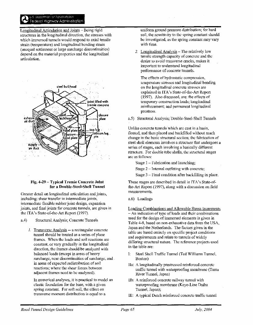
Longitudinal Articulation and Joints - Being rigidstructures in the longitudinal direction, the stresses withwhich immersed tunnels would respond to axial tensilestrain (temperature) and longitudinal bending strain(unequal settlement or large surcharge discontinuities)depend on the material properties and the longitudinalarticulation.
"dOlureplJle
Fig. 4-29 - Typical Tremie Concrete Jointfor a Double-Steel-Shell Tunnel
Greater detail on longitudinal articulation and joints,including: shear transfer in intermediate joints,intermediate flexible rubber joint design, expansionjoints, and final joints for concrete tunnels, are given inthe ITA's State-of-the-Art Report (1997).
a.4) Structural Analysis; Concrete Tunnels
1. Transverse Analysis -- a rectangular concretetunnel should be treated as a series ofplaneframes. When the loads and soil reactions areconstant, or vary gradually in the longitudinaldirection, the frames should be analyzed withbalanced loads (except in areas ofheavysurcharge, near discontinuities of surcharge, and "in areas of expected redistribution of soilreactions; where the shear forces betweenadjacent frames need to be analyzed).
In numerical analyses, it is practical to model anelastic foundation for the base, with a givenspring constant. For soft soil, the effect ontransverse moment distribution is equal to a
uniform ground pressure distribution; for hardsoil, the sensitivity to the spring constant shouldbe investigated, as the spring constant may varywith time.
2. Longitudinal Analysis - The relatively lowtensile strength capacity of concrete and thedesire to avoid transverse cracks, makes itimportant to understand longitudinalperformance of concrete tunnels.
The effects of hydrostatic compression,temperature stresses and longitudinal bendingon the longitudinal concrete stresses areexplained in ITA's State-of-the-Art Report(1997). Also discussed, are: the effects oftemporary construction loads; longitudinalreinforcement; and permanent longitudinalprestress.
a.5) Structural Analysis; Doub1e-Stee1-Shell Tunnels
Unlike concrete tunnels which are cast in a basin,floated, and then placed and backfilled without muchchange in the basic structural section; the fabrication ofsteel shell elements involves a structure that undergoes aseries of stages, each involving a basically differentstructure. For double tube shells, the structural stagesare as follows:
Stage 1 - Fabrication and launching;
Stage 2 - Internal outfitting with concrete;
Stage 3 - Final condition after backfilling in place.
These stages are described in detail in ITA's State-ofthe-Art Report (1997), along with a discussion on fieldmeasurements.
a.6) Loadings
Loading Combinations and Allowable Stress Increments- An indication of type of loads and their combinationsused for the design of immersed elements is given inTable 4-8, based on non-exhaustive data from the USA,Japan and the Netherlands. The factors given in thetable are based entirely on specific project conditionsand requirements and relate to tunnels of widelydiffering structural nature. The reference projects usedin the table are:
I: Steel Shell Traffic Tunnel (Ted Williams Tunnel,Boston)
IIa: A longitudinally prestressed reinforced concretetraffic tunnel with waterproofing membrane (TamaRiver Tunnel, Japan)
IIb: A reinforced concrete railway tunnel withwaterproofing membrane (Keyo-Line DaibaTunnel, Japan);
III: A typical Dutch reinforced concrete traffic tunnel
Road Tunnel Design Guidelines Page 65 July, 2004
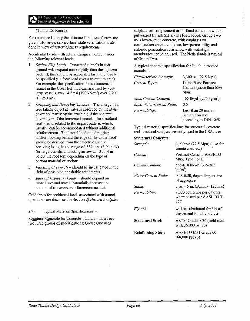
3,300 psi (22.5 Mpa).
Dutch Blast FurnaceCement (more than 65%Slag)
465 Ib/yd3 (275 kg/m3)
0.5
Less than 20 mm inpenetration test,according to DIN 1048.
4,000 psi (27.5 Mpa) (also fortremie concrete)
Portland Cement: AASHTOM85, Type I or II
565-610 Ib/yd3 (335-362kg/m3
)
0.48-0.50, depending on sizeofaggregate
2 in. - 5 in. (50mm - 125mm)
2,000 coulombs per 6 hours,where tested per AASHTO T277
Cement:
Water/Cement Ratio:
Cement Content:
Typical material specifications for structural concreteand structural steel, as presently used in the USA, are:
Structural Concrete:
Strength:
Characteristic Strength:
Cement Types:
Slump
Permeability:
sulphate-resisting cement or Portland cement to whichpulverized fly ash (p.f.a.) has been added; Group Twouses lower-grade concrete, with emphasis onconstruction crack avoidance, low permeability andchloride penetration resistance, with watertightmembranes not being used. The Netherlands is typicalof Group Two.
A typical concrete specification for Dutch immersedtunnels is:
Max. Cement Content:
Max. Water/Cement Ratio:
Permeability:
(Tunnel De Noord).
For reference II, only the ultimate-limit state factors aregiven. However, service-limit state verification is alsodone in view of watertightness requirements.
Accidental Loads - Structural design should considerthe following relevant loads:
1. Sunken Ship Loads - Immersed tunnels in softground will respond more rigidly than the adjacentbackfill; this should be accounted for in the load tobe specified (uniform load over a minimum area).For example, the specification for an immersedtunnel in the Great Belt in Denmark used by verylarge vessels, was 14.5 psi (100 kN/m2
) over 2,700ft2 (250 m2
).
2. Dropping and Dragging Anchors - The energy of afree falling object in water is absorbed by the stonecover and partly by the crushing of the concretecover layer of the immersed tunnel. The structuralroof load is related to the impact pattern, which,usually, can be accommodated without additionalreinforcement. The lateral load of a dragginganchor hooking behind the edge of the tunnel roofshould be derived from the effective anchorbreaking loads, in the range of 337 tons (3,000 kN)for large vessels, and acting as low as 13 ft (4 m)below the roof top; depending on the type ofbottom material or anchor.
3. Flooding ofTunnels - should be investigated in thelight ofpossible undesirable settlements.
4. Internal Explosion Loads - should depend ontunnel use; and may substantially increase theamount of transverse reinforcement needed.
Guidelines for accidental loads associated with tunneloperations are discussed in Section d) Hazard Analysis.
a.7) Typical Material Specifications --
Structural Concrete for Concrete Tunnels - There aretwo main groups of specifications: Group One uses
Fly Ash
Structnral Steel:
Reinforcing Steel:
will be substituted for 5% ofthe cement for all concrete.
ASTM Grade A 36 (mild steelwith 36,000 psi yp)
AASHTO M31 Grade 60(60,000 psi yp).
Road Tunnel Design Guidelines Page 66 July, 2004
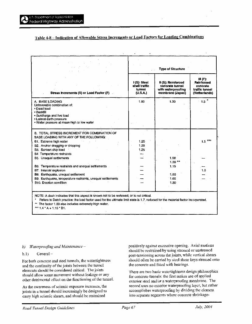
Table 4-8 - Indication of Allowable Stress Increments or Load Factors for Loading Combinations
Type of Structure
I (S): Steel II (S): ReinforcedIII (F):
Reinforcedshell traffic concrete tunnel concrete
tunnel with waterproofing traffic tunnelStress Increments (8) or Load Factor (F) (U.S.A.) membrane (Japan) (Netherlands)
A. BASE LOADING 1.00 1.00 1.5 *Unfavorable combination of:" Dead load• Backfill• Surcharge and live load• Lateral earth pressure• Water pressure at mean high or low water
B. TOTAL STRESS INCREMENT FOR COMBINATION OFBASE LOADING WITH ANY OF THE FOLLOWING: ~
B1. Extreme high water 1.25 1.5 ***B2. Anchor dragging or dropping 1.25B3. Sunken Ship load 1.25B4 Temperature restraints -B5. Unequal settlements - 1.00 -
1.30 **B6. Temperature restraints and unequal settlements - 1.15 -B7. Internal explosion - 1.068. Earthquake, unequal settlement - 1.50 -89. Earthquake, temperature restraints, unequal settlements - 1.65 -810. Erection condition - 1.30
NOTE: A dash indicates that this aspect is known not to be reviewed, or is not critical.* Refers to Dutch practice: the load factor used for the ultimate limit state is 1.7, reduced for the material factor incorporated.** The factor 1.30 also includes extremely high water.***1.4·A+1.15·B1.
b) Waterproofing and Maintenance ~
b.l) General-
For both concrete and steel tunnels, the watertightnessand the continuity of the joints between the tunnelelements should be considered critical. The jointsshould allow some movement without leakage or anyother detrimental effect on the functioning of the tunnel.
As the awareness of seismic exposure increases, thejoints in a tunnel should increasingly be designed tocarry high seismic shears, and should be restrained
positively against excessive opening. Axial motionsshould be restrained by using stressed or unstressedpost-tensioning across the joints, while vertical shearsshould often be carried by steel shear keys stressed ontothe concrete and fitted with bearings.
There are two basic watertightness design philosophiesfor concrete tunnels: the first makes use of appliedexterior steel and/or a waterproofing membrane. Thesecond uses no exterior waterproofing layer, but ratheraccomplishes waterproofing by dividing the elementinto separate segments where concrete shrinkage-
Road Tunnel Design Guidelines Page 67 July, 2004
cracking can be prevented.
Being completely enclosed by a steel shell, for steeltubes, the issue of waterproofing largely concerns thedesign of the joint between elements, and corrosion ofthe steel.
b.2) Steel Tunnels -
For the Ted Williams Tunnel in Boston, the design ofthe gasketted joint was revised to accomplish twoobjectives:
1. Make the joint flexible, to prevent damage to theseal resulting from motions observed on similartunnels, and;
2. Provide a controlled location for the movement inthe joint to appear in the surface of the wall.
This flexible joint detail (Fig. 4-30) is used in a steeltunnel for the first time in the USA, and is very similarto that commonly used in Europe for concrete tunnels.Typical joints and contingency method for sealing themare discussed in ITA (1997).
b.3) Concrete Tunnels-
Alternatives to the steel shell were developed in Europebecause steel is expensive. Problems have occurredbecause the concrete was not watertight due to cracksand lack of density.
Leakage water can enter the tunnel in two ways:
• Through the concrete structure;
• Through the joints.
These types of leakage are discussed in detail in ITA(1997).
b.3) Maintenance -
Leakage in Steel Tunnels - watertightness in steeltunnels depends primarily on the care with which theintegrity ofthe steel shell is maintained through designand fabrication. Therefore, tunnel specifications shouldrequire suitable welder qualifications, as well asradiographic, ultrasonic, and dye penetration methods ofweld inspection and tests for watertightness duringfabrication.
Permanent penetrations of the shell should be avoidedwhenever possible in the design. Where openings areprovided for access or concrete placement, great care
should be taken to inspect and test welds ofthe closureplates for watertightness.
While rare, a leakage problem when it occurs, mostoften occurs at the terminal joints with the land section,at the transition from a totally enclosing steel shell to aconventional externally applied structural waterproofingsystem. Furthermore, it may be difficult to keep theexcavation area dry where the waterproofmg is beinginstalled; hence proper detailing at this interface iscritical.
b.4) Leakage in Concrete Tunnels-
Leakages have mostly concerned minor leakage throughthe floor, walls and roof. In tunnels with membranes,leakage through cracks in the floor or walls is difficultto repair because it is almost impossible to find wherethe corresponding leak in the membrane is located. Insuch cases, the leakage is stopped by injecting allcracks, in the absence ofwater flow.
e) Environmental Issues -
This section identifies specific aspects of immersedtunnel design and construction that commonly causeenvironmental concern and gives recommendations forgood practice. It neither comments on proceduralmatters nor addresses the broader issue ofenvironmentally sustainable transport policy.
c.l) Effects on Watercourses -
• Changes in flow patterns and patterns of scour andsiltation; pollution of the water course; and effectson aquatic life; should all be considered during theconceptual planning process.
• Planners should begin collecting data on behaviorof the watercourse as soon as the possibility of animmersed tunnel crossing is established;
• Problems associated with currents, tides,variations in salinity, sediment transport, scourand siltation should be considered; hydraulicstudies, including numerical rather than physicalmodeling, should be performed;
• Contracts should be drafted to strike a balancebetween control and cost of disposal ofdredgedmaterial.
Road Tunnel Design Guidelines Page 68 July, 2004
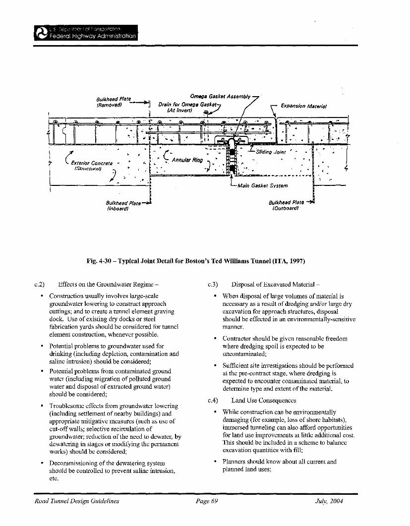
\ .. ~.
.' ·l~ ,,: ':r. .. ,
Omega GlIsket Assembly
Drllin for Omega GlISket(At InvertJ
t ," P .( ·AnnUllIf RIng •"- "".,.... .J'" . If-
: -, "'1 ... "...
: .,:~i•.~~~~'.~j'._,.':: ~ ~:I': :! .. ;'. 6 ..' II ," . ---." ,I I
..
Bulkhead PllIt~1(RemovedJ I
~
c:.xteflor Concrete(SllIIcrur,,1I
)
l\I
;.
I
ifI
Bulkhelld Plate(InbollrdJ
Bulkhelld Plate(OutbollrdJ
Fig. 4-30 - Typical Joint Detail for Boston's Ted Williams Tunnel (ITA, 1997)
c.2) Effects on the Groundwater Regime - c.3) Disposal of Excavated Material -
• Construction usually involves large-scalegroundwater lowering to construct approachcuttings; and to create a tunnel element gravingdock. Use of existing dry docks or steelfabrication yards should be considered for tunnelelement construction, whenever possible.
• Potential problems to groundwater used fordrinking (including depletion, contamination andsaline intrusion) should be considered;
• Potential problems from contaminated groundwater (including migration of polluted groundwater and disposal of extracted ground water)should be considered;
• Troublesome effects from groundwater lowering(including settlement of nearby buildings) andappropriate mitigative measures (such as use ofcut-off walls; selective recirculation ofgroundwater; reduction of the need to dewater, bydewatering in stages or modifying the permanentworks) should be considered;
• Decommissioning of the dewatering systemshould be controlled to prevent saline intrusion,etc.
• When disposal oflarge volumes of material isnecessary as a result of dredging and/or large dryexcavation for approach structures, disposalshould be effected in an environmentally-sensitivemanner.
• Contractor should be given reasonable freedomwhere dredging spoil is expected to beuncontaminated;
• Sufficient site investigations should be performedat the pre-contract stage, where dredging isexpected to encounter contaminated material, todetermine type and extent of the materiaL
c.4) Land Use Consequences
• While construction can be environmentallydamaging (for example, loss of shore habitats),immersed tunneling can also afford opportunitiesfor land use improvements at little additional cost.This should be included in a scheme to balanceexcavation quantities with fill;
• Planners should know about all current andplanned land uses;
Road Tunnel Design Guidelines Page 69 July, 2004
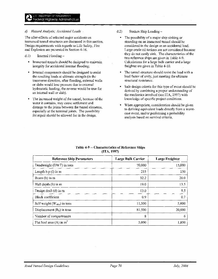
d) Hazard Analysis; Accidental Loads -
The after-effects of selected major accidents onimmersed tunnel structures are discussed in this section.Design requirements with regards to Life Safety, Fireand Explosion are presented in Section 4-16.
d.1) Internal Flooding -
• Immersed tunnels should be designed to maintainintegrity for accidental internal flooding;
• Internal components should be designed to resistthe resulting loads at ultimate strength (in thetransverse direction, after flooding, external wallsor slabs would lose pressure due to externalhydrostatic loading; the reverse would be true foran internal wall or slab).
• The increased weight of the tunnel, because of thewater it contains, may cause settlement anddamage to the joints between the tunnel elements,especially at the terminal joints. The possibilityfor repair should be allowed for in the design.
d.2) Sunken Ship Loading -
• The possibility ofa major ship sinking orstranding on an immersed tunnel should beconsidered in the design as an accidental load.Large crude oil tankers are not considered becausethey do not easily sink. The characteristics of thetwo reference ships are given in Table 4-9.Calculations for a large bulk carrier and a largefreighter are given in Table 4-10.
• The tunnel structure should resist the load with aload factor of unity, just meeting the ultimatestructural resistance.
• Safe design criteria for this type of event should bederived by combining a proper understanding ofthe mechanics involved (see ITA, 1997) withknowledge of specific project conditions.
• When appropriate, consideration should be givento deriving equivalent loads directly from a worstcase event, and/or performing a probabilityanalysis based on survival criteria.
Table 4-9 -- Characteristics of Reference Ships(ITA,1997)
Reference Ship Parameters Large Bulk Carrier Large Freighter
Deadweight (DWT) in tons 70,000 15,000
Length b.p (1) in m 215 150
Beam (b) inm 32.2 20.0
Hull depth (h) in m 19.0 13.5
Design draft (d) in m 13.0 9.5
Block coefficient 0.9 0.7
Self weight (Wship) in tons 11,500 5,000
Displacement (Bo) in tons 81,500 20,000
Number of compartments 8 6
Flat keel area (A) in m2 5,000 1,800
Road Tunnel Design Guidelines Page 70 July, 2004
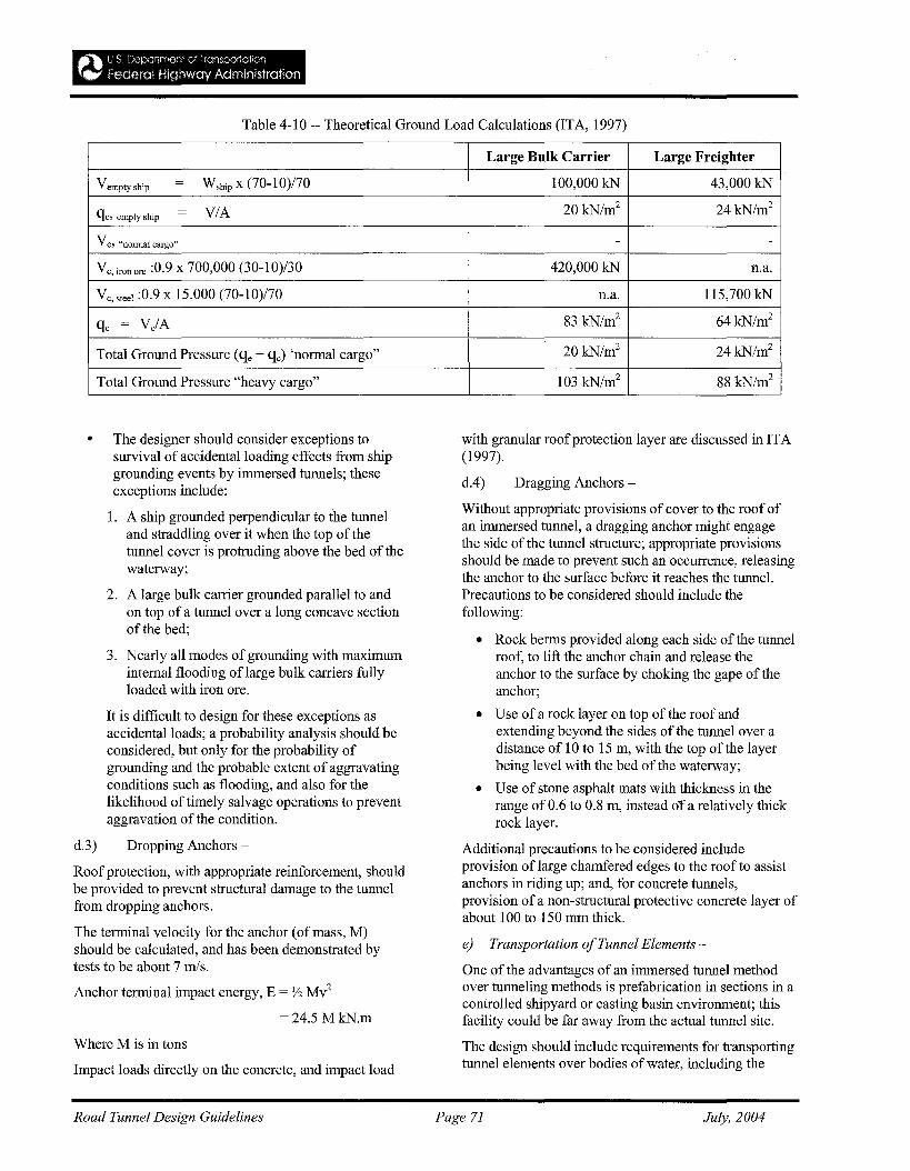
Table 4-10 -- Theoretical Ground Load Calculations (ITA, 1997)
V e, steel :0.9 X 15,000 (70-10)/70
Ve,ironore :0.9 x 700,000 (30-10)/30
Total Ground Pressure "heavy cargo"
Large Bulk Carrier Large Freighter
100,000 kN 43,000 kN
20 kN/m2 24 kN/m2
- -
420,000 kN n.a.
n.a. 115,700 kN
83 kN/m2 64 kN/m2
20 kN/m2 24kN/m2
103 kN/m2 88 kN/m2
VIA
W ship x (70-10)/70
qe. empty ship
vc, "normal cargo"
Vemptyship
Total Ground Pressure (qe + qe) 'normal cargo"
• The designer should consider exceptions tosurvival of accidental loading effects from shipgrounding events by immersed tunnels; theseexceptions include:
1. A ship grounded perpendicular to the tunneland straddling over it when the top of thetunnel cover is protruding above the bed of thewaterway;
2. A large bulk carrier grounded parallel to andon top of a tunnel over a long concave sectionofthe bed;
3. Nearly all modes of grounding with maximuminternal flooding of large bulk carriers fullyloaded with iron ore.
It is difficult to design for these exceptions asaccidental loads; a probability analysis should beconsidered, but only for the probability ofgrounding and the probable extent of aggravatingconditions such as flooding, and also for thelikelihood of timely salvage operations to preventaggravation of the condition.
d.3) Dropping Anchors -
Roof protection, with appropriate reinforcement, shouldbe provided to prevent structural damage to the tunnelfrom dropping anchors.
The terminal velocity for the anchor (of mass, M)should be calculated, and has been demonstrated bytests to be about 7 mls.
Anchor terminal impact energy, E = Y2 M~
=24.5 MkN.m
Where M is in tons
Impact loads directly on the concrete, and impact load
with granular roof protection layer are discussed in ITA(1997).
dA) Dragging Anchors-
Without appropriate provisions of cover to the roof ofan immersed tunnel, a dragging anchor might engagethe side of the tunnel structure; appropriate provisionsshould be made to prevent such an occurrence, releasingthe anchor to the surface before it reaches the tunnel.Precautions to be considered should include thefollowing:
• Rock berms provided along each side of the tunnelroof, to lift the anchor chain and release theanchor to the surface by choking the gape of theanchor;
• Use of a rock layer on top of the roof andextending beyond the sides of the tunnel over adistance of 10 to 15 m, with the top of the layerbeing level with the bed of the waterway;
• Use of stone asphalt mats with thickness in therange of 0.6 to 0.8 m, instead of a relatively thickrock layer.
Additional precautions to be considered includeprovision of large chamfered edges to the roof to assistanchors in riding up; and, for concrete tunnels,provision of a non-structural protective concrete layer ofabout 100 to 150 mm thick.
e) Transportation ofTunnel Elements-
One of the advantages of an immersed tunnel methodover tunneling methods is prefabrication in sections in acontrolled shipyard or casting basin environment; thisfacility could be far away from the actual tunnel site.
The design should include requirements for transportingtunnel elements over bodies of water, including the
Road Tunnel Design Guidelines Page 71 July, 2004
open ocean. Consideration should be given to thefollowing:
I. Most tunnel elements are blunt-ended, resulting inslow towing speeds and difficult maneuverability;
2. There is no redundancy in flotation to protect theelement from sinking if the hull is breached orcracks; furthermore, freeboard is as low as 4 in(100 mm) for some concrete elements, leavingthem little spare floating capacity;
3. More severe loading cases can apply duringtransportation than permanent loads (differentialand external loads). The design of the elementand provisions for the method of transport shouldtake into account load cases during transportresulting from factors, such as:
• Weight of the end bulkheads;
• Equipment mounted on the element forplacing;
• Temporary mounting or support of the elementduring transport;
• Offshore wave height and period;
• Structural staging of the element at the time oftransport.
Details on: transportation route; preparation fortransport; internal forces during transport; towingforces; nautical aspects; hydraulic model tests;transportation by barge, and; examples of inland andoffshore transportation; are provided in ITA (1997).
4-10 Cut-and-Cover Tunnel Structures
a) Tunnel Design - Structural
a.l) General -
The cut-and-cover structure should be designed tosafely resist all loads expected over its life; the principalloads are: long-term development of water and earthpressures; dead load, including weight of earth cover;surface surcharge load; and live load. Load categoriesshould be in accordance with AASHTO StandardSpecifications, and should represent the requirements ofthe particular cut-and-cover structure underconsideration. Earthquake forces are discussed in 4-11.
a.2) Dead Load
Dead load should consist of the following:
1. Weight of the basic structure;
2. Weight of secondary elements permanentlysupported by the structure;
3. Weight of the earth cover supported by the roofof the structure and acting as a simple gravityload.
4. In order to factor in future loadings over shallowvehicular tunnels (e.g., special vehicle loadings inexcess of normal axle loads, and future buildingloads, etc.), the structure should be designed for aminimum vertical load equivalent to 8 ft (2.45m)of earth cover, regardless of actual cover.
a.3) Live Load, Impact and Other Dynamic Forces
Live load, impact and other dynamic forces imparted tocut-and-cover vehicular tunnels and their application,should conform to, or exceed, the requirementscontained in the AASHTO specifications for HS20-44loading.
a.4) Horizontal Earth Pressure-
Horizontal earth pressure, lateral pressure due to bothretained soil and retained water in soil when water ispresent, may include the effect of surcharge loadingresulting form adjacent building foundation loading,surface traffic loading, or other surface live loading. Allof these components should be evaluated both in termsofpresent and future conditions, particularlygroundwater levels.
When future changes could adversely affect thesubsurface structure, needed protective measures tomitigate adverse effects might not be foreseen, andmight be extremely costly to add to an existingstructure.
The short-term and long-term changes in horizontalearth pressure should be considered, and cut-and-covertunnels should be designed for both short-term andlong-term loading. Immediately following construction,the actual short-term earth pressure may be considerablyless than long-term design pressure.
To provide a competent factor of safety against futuremishap resulting from adjacent construction, the tunnelsshould be proportioned for side sway, if a single-storystructure; and side sway should be considered in theupper story only, in the case of two or more stories.
a.5) Buoyancy -
When the groundwater table lies above the bottom ofthe invert or base slab of a subsurface structure, anupward pressure on the bottom of the base slab, equal tothe piezometric head at that level, should be accountedfor.
When B (the buoyant force per lineal feet of structure)exceeds DL min. (the reliable minimum weight of thestructure plus the fill above the structure), otherresisting features should be incorporated into the design,including the following:
• The weight of the structure may be increased bythickening the walls, roof or base slab; the baseslab may also be widened to increase the weight
Road Tunnel Design Guidelines Page 72 July, 2004
of earth resistance;
• Tension piles designed to provide a tensile forceon the base slab should be provided; both steelpiles and precast concrete piles have been used inthis application;
• Tie-down anchors, resembling permanent tieback anchors, should be provided; drilling for theanchors is accomplished at some convenient timeafter the base slab is placed. The anchor headsare located in formed recesses in the base slab.After completion of the tie-down installation, therecess is filled with concrete. The type of anchorused will depend in part on whether the anchorcan be founded in bedrock beneath the structure,or in competent soil.
a.5) Flood-
Where a potential for river floods, or other flooding thatcould add loads to subsurface structures, the design forthe structures should allow for this loading, as requiredby the particular type of structure and the conditionsaffecting each location.
a.6) Shrinkage and Thermal Forces-
Shrinkage forces and thermal forces between transversejoints should be accounted for by the longitudinalreinforcement in the walls, roof, and invert slab; thestresses produced by these forces should not enter into
frame analysis of the structure (as they are typicallynormal to the principal stresses caused by DL, LL, andI).
a.7) Loading Cases -
The particular load cases to be analyzed should dependon the type of structure, its location, the type ofgroundin which the structure is founded, location of thegroundwater table, and other local factors.
All reasonable foreseeable temporary and permanentloading cases that would affect the design of thestructure should be investigated.
a.8) Frame Analysis -
Loads and pressures representing each loading case areapplied, and the shears, thrusts and bending momentsfor each element of the frame are determined throughrigid frame analysis using commonly acceptedmethodology (usually contained in structural analysiscomputer programs).
Except for particularly wide invert spans, it should beassumed that the vertical reactions are uniformlydistributed over the bottom ofthe invert slab,conservatively resulting in maximum slab bendingmoments.
Figures 4-3la and 4-31b contain illustrations of threeloading cases applied to a reinforced concrete structureand the configuration of each resulting bending momentdiagram.
Road Tunnel Design Guidelines Page 73 July, 2004
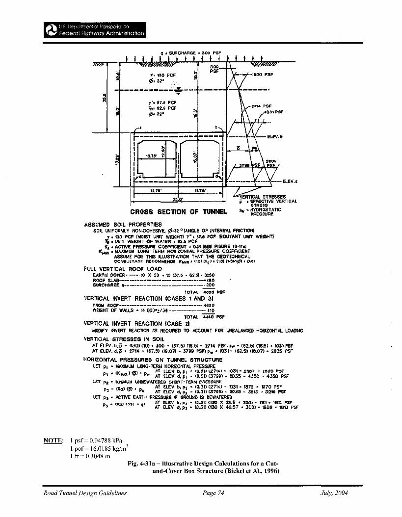
f',au, PCFTw' eu PCI'1Z5' 3~"
CROSS SECnON OF TUNNEL
ASSUMED SOIL PROPERliESSOlI. lMlFORMl Y NON·COHESIVe.. ¢.32 ~ IANG~e OF Il'ffeRNI\L FRICTlOtoiI
., • 130 f'CF 1I\II0IS1 UMT WEIGHTI y·. &7.6 l>OF IeOtJ't'IINT UNIT WEIGHTl~ • utIlT WeIGHT OF WAT£PI ,6M POFK. • ACTIVE PRESSURE OoeFflOIENT • Q,J,tISEE FIGURE 16·1~.1
l(W\l • MAXIMUM LONG TERM HORIZONTAl. PRiSSUFtC OOErflOENT.ASSUME FOR THIS LlUSTflATION THAT lIE GEOTEOHl\1IOALeON$UlTANT fleCOMN!I!HDS K r.r.uc • '131I)(D)' fl..31 11·$1Il¢1. CMI1
FUl.l VERTICAL ROOF l.OAOEAATH COveFl----' 10 X 30 • ~ 1&1.6 • $~.51. 3250ROOF Sl..IlB·_·-··_·_·_·_··_·__·_···_--_·_··-- ~10SUACHJl.RGE. q---.--------------------------1I00
10r",-.. -4"110 P9FVERlICAl INVERT REACTION (CASES 1 AND 31
'''OM ltQQF-------------------.---------- 411ilOWtlGHT OF W.AJ..I.S - 14,OOO".t/J4 --------.-.-- 41(1
TOTAL 4«ii" PSFVERTICAL INVERT REAOTION CCASE 21
UOOIFY INVERT fi(JlClION .IIS REQlJllED 10 ACCOllllT fOR uteAI.JHCEDHORJZONT14. LO.-DNG
veRTICAL STREsses IN SOILAT £tE\". b, po - flJOl no) • 300 • '&;.51 mS.51 - 2114 PSf'~ POw - (62.5) (1M,1 .. 1031 PSFAT REV. d. Ii • :2114 • (67.5) (18.01) ~ 3799 PSF; Pw .. '1031- 1&2.5) <11$.071 - 2035 !'SF
HORIZONiAL PRESSURes ON TUNNEl. STRUOTURe:I.ET p, .. UAXIWU'tl L(lI'lQ~ tERM HORIZONTAl. PRESSURE
P1 & (I( ) (ji~ • ''L. AT .!:L.f;V b, PI" ~o.em 127141 • 1)J1 - 2/li1:l7 .. ~(lW PSI'"IU,\( r-... AT £LEV d, Pl" ({I.fi11 (3799) • :r035 - 4352 -4350 PSF'
Ltt Pit .. MNMUhl UNOEWATEA£:tl SHlH'tT-fE:fthl PRESSlJfl:E~ _ (K<:I) ~, 'L Ai fi.EV b. FIt .. (o.:m (21'1<1-'. 1031 - 1sn .. 111170 FSF
2 ..........T £U:V d, Pi - (0.311 (3799) • !03S - ,uU - 32tlJ PSflET p) .. ACTIVE: EAAnI PRESS1JRE IF' GROIJNl) IS DEWATERO
P .. (KG) (rH .. q) AT EI.Ellb, p~ - (O.31l <130 )It 2:.&,,5 • 300) .. 111$1 .. 1I8C P15FJ. AT EL.E:V d. P3 " 10.31) nJO x 42.57 • 3000) .. 1809 .. 11ln PSt
NOTE: 1 psf= 0.04788 kPa1 pcf= 16.0185 kg/m3
1 ft = 0.3048 mFig. 4-31a - Illustrative Design Calculations for a Cut
and·Cover Box Structure (Bickel et AI., 1996)
Road Tunnel Design Guidelines Page 74 July, 2004
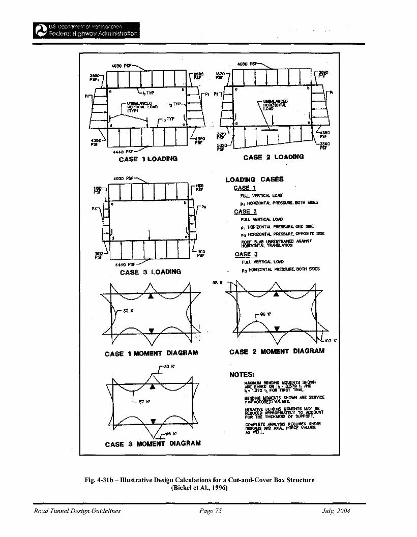
PI
CASE 3 LOADING
CASE 1 MOMENT DIAGRAM
:..;::.''15 It'
CASE 3 MOMENT DIAGRAM
98 1('
CASE 2 LOADING
LOADING CASESCASE 1
F'ULL VERTIC~ LO~
p, HClRIZOHT"I. PRESSURE. BOTH SIDES
CAse 2FULL VERTICAl LOAD
1', HORIZONTAL PRESSlflE. ONE: SU
P:r HllRlZONTA. PRESSiJRE, OPPOSITE S1D£
ROOf' $lAI ltIR£STRM4ED NlAI4STHORIZQNT~ TRHfSLATlON
CASE 3FULlVERTlC.AL LO~
I'll HORIZONTAL PRESSURE.OOTlI SIDES
CASE 2 MOMENT DIAGRAM
NOTES:M..-.uhl SENDlNllhlOMENTS SHOWN.ME BASED ON 12·0.579 II JtlO.... 1.372 It FOR FIRST 1Tl!Al.
BENOINtl UOME:NTS SHOWN ARE SERVICEW!'F,!,CTORED} VALIIES.
NEGATIVE 'hlOMENTS WAY BERtDUCIiD :rELY TO ":;COUNTFOR THE Of SUPPORT.
COWL£TE NUl."$IS REQUIflf:S SHEARDIGFW.IS 1HD AXl"l. fORCE V1l.ue:S#IS WELL.
Fig. 4-31b - Illustrative Design Calculations for a Cut-and-Cover Box Structure(Bickel et AI., 1996)
Road Tunnel Design Guidelines Page 75 July, 2004
It should be noted that in frame analysis, the crackedmoment of inertia (Ie) is typically much less than thegross moment of inertia (Ig). If strains are not aconcern, gross values of EI should be used since onlyrelative internal reactions (forces and moments) aredesired.
a.9) Reinforced Concrete Design
Design should be carried out according to AASHTOspecifications in the design of reinforced concrete forcut-and-cover road tunnels. The design must alsoconform to all local and other mandated codes, exceptwhen particular provisions of those codes can be shownnot to be applicable.
Where earthquake forces are a factor, the structureshould be designed for a desired degree of ductility andtoughness as well. To incorporate these provisions intoreinforced concrete design, authoritative and pertinentliterature on the subject of seismic design should beconsulted.
Minimum requirements for shrinkage and temperaturereinforcement, as specified by AASHTO, have not beenconsidered applicable for cut-and-cover road tunnels.For the design of road tunnel walls and roof slabs, withtransverse joints about 50 ft apart, it is common toprovide temperature and shrinkage reinforcement, onboth faces of the wall or slab, in the amount of 80 to 100percent of normal ACI 318 (7.12) requirements, up to aspecified maximum. Treatment of invert slabs has beensimilar to that of walls and roof slabs. In some cases,subgrade drag may need to be investigate
b) Shoring Systems-
To prevent detrimental settlement of the ground,utilities, and adjacent structures, temporary walls orshoring walls have to be in place before significant cutand-cover excavation commences.
The design of the support system should considerfactors including the following:
• Physical properties of the soil throughout andbeneath the cut;
• Position of the groundwater table duringconstruction;
• Width and depth of excavation;
• Configuration of the subsurface structure to beconstructed within the cut;
• Size, foundation design and proximity of adjacentstructures; .
• Number, size and type of utilities crossing theproposed excavation, or adjacent to theexcavation;
• Requirements for street decking across theexcavation;
• Traffic and construction equipment surchargeadjacent to the excavation;
• Noise restrictions in urban areas.
Authoritative and pertinent literature on the subject ofshoring walls should be consulted for types of walls andwall support; design; and performance of shoringsystems. An excellent reference on allowablemovement of excavation support system is
c) Decking
Decking consists of deck framing and roadway decking.Figures 4-32 a and b illustrate a typical generalarrangement for street decking over a cut-and-coverexcavation.
For cut-and-cover road tunnels, similar to cut-and-coverfor rapid transit structures (SFBART, WMATA, etc),deck framing should be designed for AASHTO HS 2044 loading, or for loading due to construction equipmentthat will operate on the deck, whichever is greater.Allowable stresses in the deck framing are limited tobasic unit stresses as prescribed by AASHTO. For deckbeams, maximum deflection due to service live load andimpact equal to 1/600 of the span is usually permitted.
When the live loads are construction equipment and thedeck is not carrying public traffic, permissibledeflection due to service live load and impact can beincreased to 1/500 of the deck beam span, and theallowable stress on the webs of cap beams may beincreased by 20%.
Fig. 4-32c illustrates an application where the structuralsteel deck beams are utilized also as struts so that thedeck structure becomes the uppermost bracing tier.
d) Excavation and Groundwater Control -
d.l) Internally Braced Excavations -
Figure 4-33 shows the general construction sequencetypically employed during construction of a cut-andcover road tunnel structure. The two most commonlyused pieces of equipment for excavating braced cuts arethe backhoe and the clamshell bucket. Extensible,vertical or inclined belt conveyors have also beenemployed to, for example, raise excavated material fromthe hole and deposit into a truck-loading bin.
Road Tunnel Design Guidelines Page 76 July, 2004
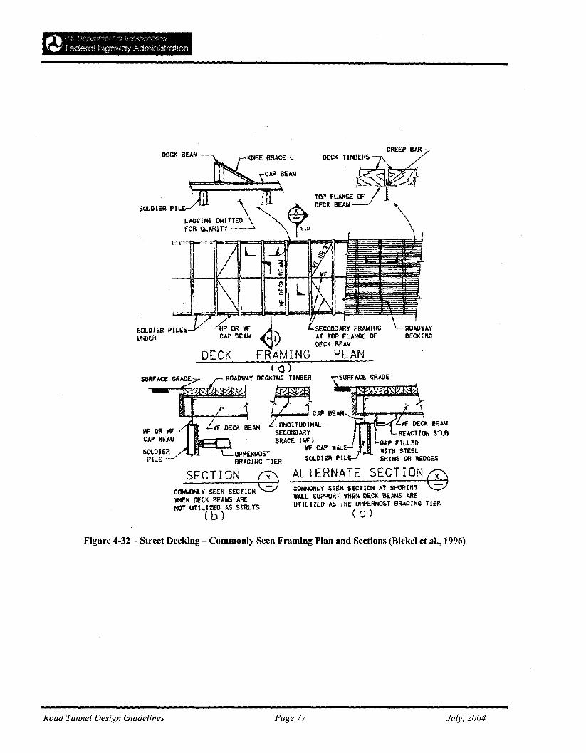
CREEP BAR
SECOkOARY FRANINGAT TOP FLANGE OFtlECI\. BEAll
PLAN
~..";.:; 4DECK FRAMING
SO\..DtER PIl.E I \
LAGGING 0"'11T£0 ~fOR CLARITY
SOLI}IER PILESUNDER.
AL TERNATE SECT ION @COl\NJtll.Y SEEN SECTION AT SHORINGWALL SUPPORT WHEI'i DECK BEANS AREUTILIZE]) AS THE UPPERNOST BRACING TIER
( c)
( a)ROADWAY DECKING UNSER SURFACE GRADE
'" DEGl< ..'" tz:1.c: .."'~OO\.~F==;F'lWF-"'OE-\CK B£A'"
SECOHOARY l REACTION STUBBRACE Illf i GAP FILLED
WF CMi "ALE WI Ttl STEELStlLlHER PIL SHINS OR WEOGES
UPPERf,(lSTBRACING TIER
SECTION @co~Y SEEN SECTIONWHEN DECK BEANS ARENOT UTILIZED AS STRUTS
( b)
Figure 4-32 - Street Decking - Commonly Seen Framing Plan and Sections (Bickel et aI., 1996)
Road Tunnel Design Guidelines Page 77 July, 2004
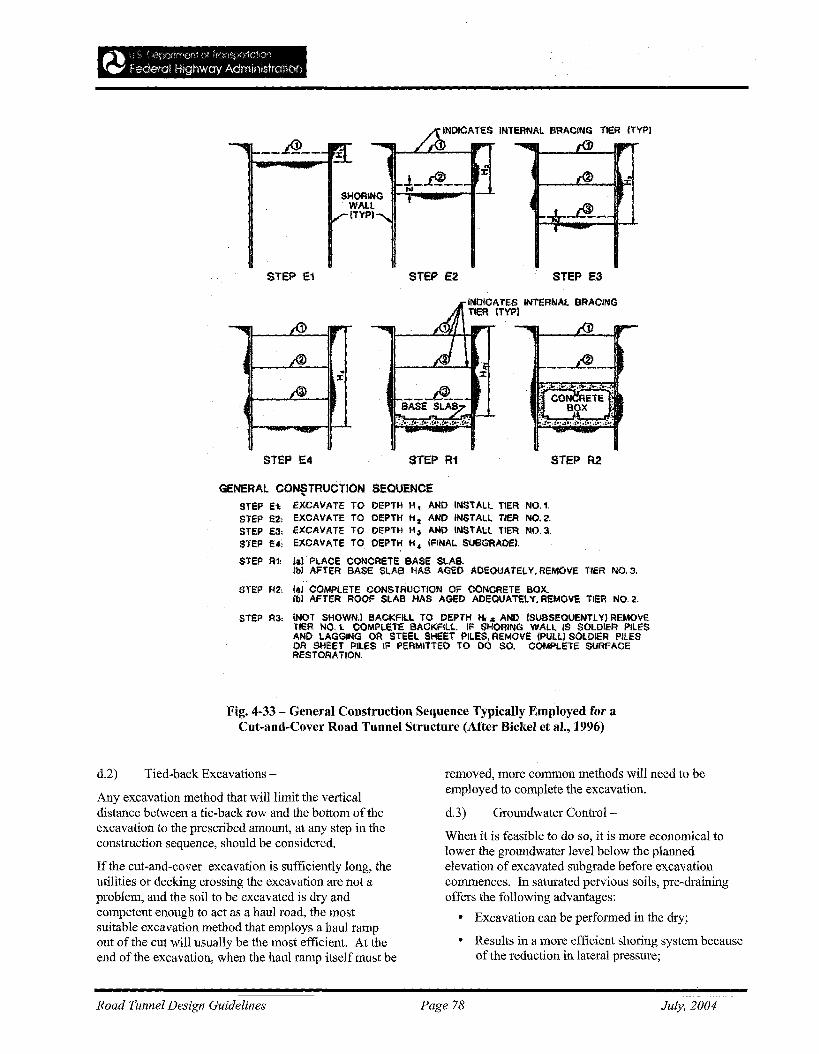
-_.&_-
STEP E1 STEP E2 STEP E3
STEP E4 STEP R1 STEP R2
GENERAL CO~TRUci;nON SEOUENCESTEP E1: EXCAVATE TO DePTH H. AND INSTALL TIER NO.1.STep £2; EXCAVATE TO OEPTH H 2 AND INSTALL TIER NO.2.STEP £3; EXCAVATE TO oePTH H" AND INSTAll TIER NO.3.STEP E'i eXCAVATE TO OEPTH H 4 (FINAL SUSGRAoel.
STep IU lal" PLAce CONCReTE BASE SlAS.Ibl AFTER BASE SLAB HAS AGeD AOEaUATELY. REMOVE ilEA NO.3.
STEP R2; fal COMPLETE CONSTRUCTION OF CONCReTE BOX.lill AFTER ROOF SLAB HAS AGEO AOeQUATElY. REMOliE TIER NO.2.
SrS? R3: {NOT SHOWN.! BACKFll.l TO DEPTH Ii, '" AND ISUBSEOUENTlYI REMOVETIER NO. 1. CQMPlET£ BACKFILL. IF SHORIIIIG WALL IS SOLDIER PILESAND LAGGING OR STEEL SHEET PilES, REMove (PULLI SOlDIeR PILESOR SHEET PILES IF peRMITTED TO DO SO. COMPLeTE SlJRFACERESTORATION.
Fig. 4-33 - General Construction Sequence Typically Employed for aCut-and-Cover Road Tunnel Structure (After Bickel et aI., 1996)
d.2) Tied-back Excavations -
Any excavation method that will limit the verticaldistance between a tie-back row and the bottom of theexcavation to the prescribed amount, at any step in theconstruction sequence, should be considered.
If the cut-and-cover excavation is sufficiently long, theutilities or decking crossing the excavation are not aproblem, and the soil to be excavated is dry andcompetent enough to act as a haul road, the mostsuitable excavation method that employs a haul rampout of the cut will usually be the most efficient. At theend of the excavation, when the haul ramp itself must be
removed, more common methods will need to beemployed to complete the excavation.
d.3) Groundwater Control-
When it is feasible to do so, it is more economical tolower the groundwater level below the plannedelevation of excavated subgrade before excavationcommences. In saturated pervious soils, pre-drainingoffers the following advantages:
• Excavation can be performed in the dry;
• Results in a more efficient shoring system becauseof the reduction in lateral pressure;
Road Tunnel Design Guidelines Page 78 July, 2004
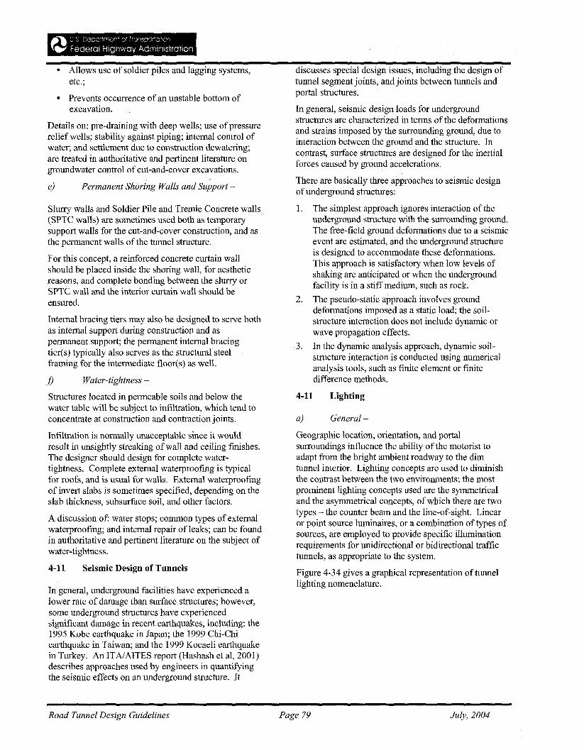
• Prevents occurrence of an unstable bottom ofexcavation.
• Allows use of soldier piles and lagging systems,etc.;
Details on: pre-draining with deep wells; use ofpressurerelief wells; stability against piping; internal control ofwater; and settlement due to construction dewatering;are treated in authoritative and pertinent literature ongroundwater control of cut-and-cover excavations.
In general, underground facilities have experienced alower rate of damage than surface structures; however,some underground structures have experiencedsignificant damage in recent earthquakes, including: the1995 Kobe earthquake in Japan; the 1999 Chi-Chiearthquake in Taiwan; and the 1999 Kocaeli earthquakein Turkey. An ITAJAITES report (Hashash et aI, 2001)describes approaches used by engineers in quantifyingthe seismic effects on an underground structure. It
a) General-
Geographic location, orientation, and portalsurroundings influence the ability of the motorist toadapt from the bright ambient roadway to the dimtunnel interior. Lighting concepts are used to diminishthe contrast between the two environments; the mostprominent lighting concepts used are the symmetricaland the asymmetrical concepts, of which there are twotypes - the counter beam and the line-of-sight. Linearor point source luminaires, or a combination of types ofsources, are employed to provide specific illuminationrequirements for unidirectional or bidirectional traffictunnels, as appropriate to the system.
Figure 4-34 gives a graphical representation of tunnellighting nomenclature.
4-11 Lighting
discusses special design issues, including the design oftunnel segment joints, and joints between tunnels andportal structures.
In general, seismic design loads for undergroundstructures are characterized in terms of the deformationsand strains imposed by the surrounding ground, due tointeraction between the ground and the structure. Incontrast, surface structures are designed for the inertialforces caused by ground accelerations.
There are basically three approaches to seismic designofunderground structures:
1. The simplest approach ignores interaction of theunderground structure with the surrounding ground.The free-field ground deformations due to a seismicevent are estimated, and the underground structureis designed to accommodate these deformations.This approach is satisfactory when low levels ofshaking are anticipated or when the undergroundfacility is in a stiff medium, such as rock.
2. The pseudo-static approach involves grounddeformations imposed as a static load; the soilstructure interaction does not include dynamic orwave propagation effects.
3. In the dynamic analysis approach, dynamic soilstructure interaction is conducted using numericalanalysis tools, such as finite element or finitedifference methods.
Permanent Shoring Walls and Support-e)
Slurry walls and Soldier Pile and Tremie Concrete walls(SPTC walls) are sometimes used both as temporarysupport walls for the cut-and-cover construction, and asthe permanent walls of the tunnel structure.
For this concept, a reinforced concrete curtain wallshould be placed inside the shoring wall, for aestheticreasons, and complete bonding between the slurry orSPTC wall and the interior curtain wall should beensured.
Internal bracing tiers may also be designed to serve bothas internal support during construction and aspermanent support; the permanent internal bracingtier(s) typically also serves as the structural steelframing for the intermediate floor(s) as well.
f) Water-tightness-
Structures located in permeable soils and below thewater table will be subject to infiltration, which tend toconcentrate at construction and contraction joints.
Infiltration is normally unacceptable since it wouldresult in unsightly streaking of wall and ceiling finishes.The designer should design for complete watertightness. Complete external waterproofing is typicalfor roofs, and is usual for walls. External waterproofingof invert slabs is sometimes specified, depending on theslab thickness, subsurface soil, and other factors.
A discussion of: water stops; common types ofexternalwaterproofing; and internal repair of leaks; can be foundin authoritative and pertinent literature on the subject ofwater-tightness.
4-11 Seismic Design of Tunnels
Road Tunnel Design Guidelines Page 79 July, 2004
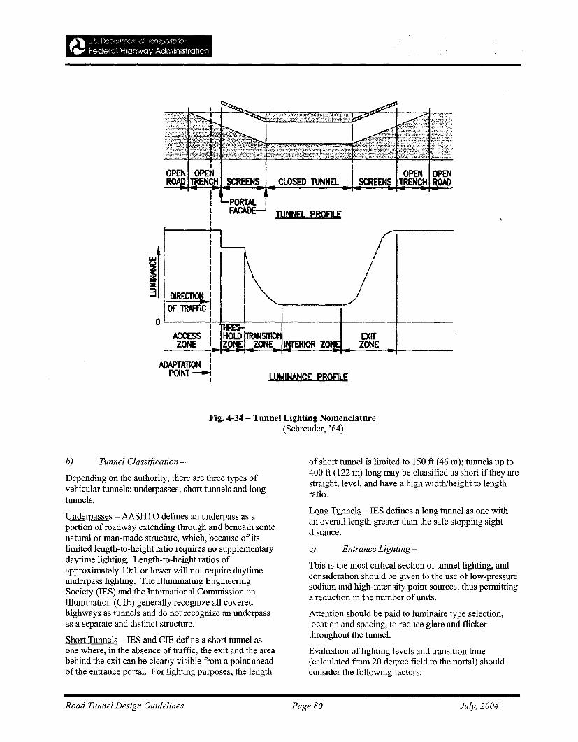
Fig. 4-34 - Tunnel Lighting Nomenclatnre(Schreuder, '64)
b) Tunnel Classification-
Depending on the authority, there are three types ofvehicular tunnels: underpasses; short tunnels and longtunnels.
Underpasses - AASHTO defines an underpass as aportion of roadway extending through and beneath somenatural or man-made structure, which, because of itslimited length-to-height ratio requires no supplementarydaytime lighting. Length-to-height ratios ofapproximately 10: I or lower will not require daytimeunderpass lighting. The Illuminating EngineeringSociety (IES) and the International Commission onIllumination (CIE) generally recognize all coveredhighways as tunnels and do not recognize an underpassas a separate and distinct structure.
Short Tunnels - IES and CIE define a short tunnel asone where, in the absence of traffic, the exit and the areabehind the exit can be clearly visible from a point aheadof the entrance portal. For lighting purposes, the length
of short tunnel is limited to 150 ft (46 m); tunnels up to400 ft (122 m) long may be classified as short if they arestraight, level, and have a high width/height to lengthratio.
Long Tunnels - IES defines a long tunnel as one withan overall length greater than the safe stopping sightdistance.
c) Entrance Lighting-
This is the most critical section of tunnel lighting, andconsideration should be given to the use of low-pressuresodium and high-intensity point sources, thus permittinga reduction in the number ofunits.
Attention should be paid to luminaire type selection,location and spacing, to reduce glare and flickerthroughout the tunnel.
Evaluation oflighting levels and transition time(calculated from 20 degree field to the portal) shouldconsider the following factors:
Road Tunnel Design Guidelines Page 80 July, 2004
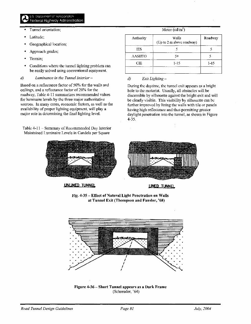
• Tunnel orientation;
• Latitude;
• Geographical location;
• Approach grades;
• Terrain;
• Conditions where the tunnel lighting problem canbe easily solved using conventional equipment.
d) Luminance in the Tunnel Interior-
Based on a reflectance factor of 50% for the walls andceilings, and a reflectance factor of 20% for theroadway, Table 4-11 summarizes recommended valuesfor luminaire levels by the three major authoritativesources. In many cases, economic factors, as well as theavailability ofproper lighting equipment, will playamajor role in determining the final lighting level.
Table 4-11- Summary of Recommended Day InteriorMaintained Luminaire Levels in Candela per Square
UNUtjED TUNNEL.
Authority Walls Roadway(Up to 2 ill above roadway)
IES 5 5
AASHTO 5+ 5+
eIE 1-15 1-15
d) Exit Lighting -
During the daytime, the tunnel exit appears as a brighthole to the motorist. Usually, all obstacles will bediscernible by silhouette against the bright exit and willbe clearly visible. This visibility by silhouette can befurther improved by lining the walls with tile or panelshaving high reflectance and thus permitting greaterdaylight penetration into the tunnel, as shown in Figure4-35.
UtjEQ TUNNEL.
Fig. 4-35 - Effect of Natural Light Penetration on Wallsat Tunnel Exit (Thompson and Fanslor, '68)
Figure 4-36 - Short Tunnel appears as a Dark Frame(Schreuder, '64)
Road Tunnel Design Guidelines Page 81 July, 2004
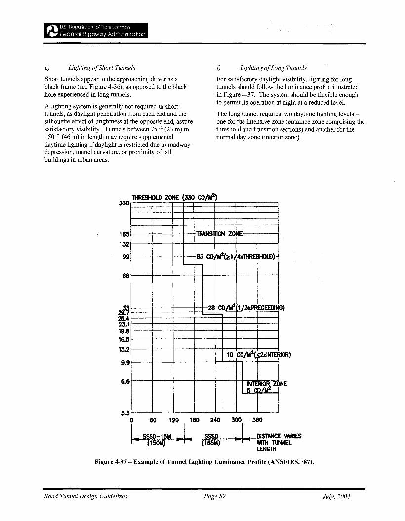
e) Lighting ofShort Tunnels-
Short tunnels appear to the approaching driver as ablack frame (see Figure 4-36), as opposed to the blackhole experienced in long tunnels.
A lighting system is generally not required in shorttunnels, as daylight penetration from each end and thesilhouette effect of brightness at the opposite end, assuresatisfactory visibility. Tunnels between 75 ft (23 m) to150 ft (46 m) in length may require supplementaldaytime lighting if daylight is restricted due to roadwaydepression, tunnel curvature, or proximity of tallbuildings in urban areas.
j) Lighting ofLong Tunnels
For satisfactory daylight visibility, lighting for longtunnels should follow the luminance profile illustratedin Figure 4-37. The system should be flexible enoughto permit its operation at night at a reduced level.
The long tunnel requires two daytime lighting levels one for the intensive zone (entrance zone comprising thethreshold and transition sections) and another for thenormal day zone (interior zone).
lOR)
0)
ZONE
TRANSI110N ZorE
83 CD ftI(~114XlHRESHOlD)
28 COlt/- 1/3xPRECEEDIN
10 COM$2xINTER
I5 criiU2
66
6.6
Jj26.423.119.816.513.2
9.9
1HRESHOlD ZONE (330 co/ti-)330
165132
99
3.3o 60 120 180
~~fM ..I..240
SSSD(165M)
300 360
..!--DlSTANCE VARIESWfTH 1\JNNELLENGTH
Figure 4-37 - Example of Tunnel Lighting Luminance Profile (ANSI/IES, '~7).
Road Tunnel Design Guidelines Page 82 July, 2004
g) Tunnel Lining
Finally, the tunnel roadway surface should have as higha reflectance factor as possible
Finally, the IES Handbook (1990) gives acomprehensive procedure for developing a meaningfulmaintenance factor.
The designer should refer to ANSIIIES RP-22,American Standard Practice for Tunnel Lighting, for useof the Zonal Cavity Method. Computer software isreadily available for illuminance and luminancecalculations.
provide the following:
1. Traffic Flow Monitoring -- Monitor traffic flow andidentify impending congestion from breakdowns oraccidents;
2. Safe Environment -- Maintain a safe tunnelenvironment responsive to traffic density and travelspeed;
3. Communications -- Communicate trafficrestrictions to motorists;
4. Emergency Response -- Mobilize requiredemergency response to clear accidents within thetunnel;
5. Emergency Systems Operations -- Initiate requiredemergency systems operations;
6. Service Equipment Monitoring -- Monitor status oftunnel service equipment
b) Design and Implementation-
Combined input from the disciplines of trafficengineering, computer/communication design, andsoftware development is required for system design.
b.l) Traditional Design Approach - involvespreparation of design plans and specifications forcontractor construction, but is usually successful onlywhen contracted directly with pre-qualified controlsystems contractors.
b.2) System Manager Approach - the systemmanager is contracted with to design and prepareprocurement and installation contracts, and isresponsible for system integration, documentation andtraining; he also provides the application software. Thecomplete control systems services package includes:Operating Manual; Maintenance Manual; Training;Provisions to supply a management staff for a specifiedperiod during start-up; and a warranty that ensuresresponsibility for a specified period, for all componentsincluding manufacturer in-house product warranties thatmay have expired.
c) Tunnel Security-
The Tunnel Designer should make special reference tothe FHWAIAASHTO Report entitled:'Recommendations for Bridge and Tunnel Security';dated September 2003, and prepared by the BlueRibbon Panel on Bridge and Tunnel Security. The BlueRibbon Panel developed strategies and practices fordeterring, disrupting, and mitigating potential attacks;they recommended policies and actions to reduce theprobability of catastrophic structural damage that couldresult in substantial human casualties, economic losses,and socio-political damage.
4-12 Fire Precautions
Emergency Lightingh)
Complete interruption of tunnel lighting isunacceptable.
h.l) Dual Utility Power Sources - one-half of thetunnel lighting is connected to each supply, sothat, in case of failure, at least one-half of thesystem remains energized until transfer of theentire load to the remaining source.
h.2) Single Utility Service and Standby Generator one-sixth of the tunnel lighting is connected to anemergency circuit, which, in case ofpowerfailure, is immediately transferred to a centralemergency battery system until the generatorpicks up to carry one-half of the tunnel lighting.
i) Design Computations
Mathematical methods of analysis (account for interreflection oflight) have led to progressively moreaccurate coefficients ofutilization data. The ZonalCavity Method improved older systems by providingincreased flexibility and accuracy in lightingcalculations.
4-11 - Tunnel Surveillance/ManagementiSecurity
a) General-
Modern roadway tunnels and their approach roadsrequire a centralized traffic control system to maintainsafety. While particular requirements vary, thefollowing minimum general surveillance and controlsystems are common to all, and should be used to
The brightness and uniformity of the interior walls andceiling of the tunnel depend on the reflectance quality ofthe surface.
The light color and high reflectance of the tunnel ceilingis desirable because of the higher wall and roadwaybrightness that will result. A light-colored matte fmishsurface with a reflectance factor of at least 70% isrecommended.
Road Tunnel Design Guidelines Page 83 July, 2004
When designing the fire protection, the heating as wellas the cooling phases of the fire cycle should be takeninto consideration.
Materials in main load-bearing systems, fittings andinstallations must not contribute to the spread of fire andfire combustible gases.
A material should be non-combustible unless thecontribution to the spread of fire by the material can beconsidered negligible.
Supplementary requirements should be specified in thetechnical description(s). The requirements should bebased on an estimate of the damage the client considersto be acceptable.
It will be accepted that attention be paid only to theheating phase when doors are designed and when thedesign is carried out by means of testing.
A tunnel should be designed so as to prevent thepropagation ofhighly inflammable or explosive gasesand fluids to side spaces. Installations that are parts ofthe safety system of the tunnel should be protectedagainst fire during the required time. The required timemust be specified in the technical specifications.
Installations should be designed so that excessiveeffects on an individual structural member will notresult in other subsequent damages.
c) Verification offire resistance
The fire resistance capacity should be verified by meansoftesting, calculation or a combination of thesealternatives.
For rock tunnels, the verification ofthe resistancecapacity is required only for the main load-bearingsystem, provided that the capacity is ensured by asupporting construction.
Structures that separate escape routes and chambers andaccess routes and escape routes should also comply withthe requirements on integrity and isolation.
It must be proved that main load-bearing systems,fittings and installations have enough capacity to resistfire effects during the time required for evacuation andrescue operations without the risk of falling parts thatcan cause local damage. Installations should complywith this requirement at temperatures below 270° C(543.2K).
It should be remembered that the chipping of concretestructures starts at a surface temperature of 150-200° C(423.2-473.2K). The speed of heating as well as thestrength and impermeability of the concrete are alsosignificant, influential factors.
a) General-
Special reference is made to FHWA Report No.FHWA-RD-83-032 entitled: 'Prevention and Control ofHighway Tunnel Fires'. This report presents methodsofpreventing, responding to, and controlling fires inexisting and future highway tunnels. The means ofevaluation of and reducing the risk for such fires andreducing damage, injuries, and fatalities are presented.The findings and recommendations of the report arebased on evaluations of: (1) experimental tunnel firetests; (2) significant highway tunnel fires; (3)observations of highway tunnels; (4) interviews withmajor highway tunnel operators; and (5) accident risksof unrestricted transit of hazardous materials. Theeffects of traffic, tunnel design, and operations on suchrisks are discussed. A ventilation system with afire/emergency operating mode is recommended.
Furthermore, the National Fire Protection Association(NFPA) has published numerous standards, codes,recommended practices, and guides for fire and safetyissues. The Tunnel Designer should refer to NFPA 502entitled: 'Standardfor Road Tunnels, Bridges and OtherLimited Access Highways', 2001 Edition.
In general, the following factors influence thedetermination of safety equipment and systems to beinstalled in a tunnel:
• Tunnellength
• Amount of traffic;
• Tunnel location (urban area, outside an urban area,underwater);
• Number of traffic lanes;
• Amount of heavy-goods traffic;
• Regulations in force for the transit of dangerousmaterial through the tunnel
The significance of time in a tunnel fire can best beidentified by the sequence of events in a fire situation asfollows:
• Time to detect a fire;
• Time to send an alarm;
• Time to verify the source of the fire;
• Time to implement emergency responseprocedures.
b) Preconditions
Building elements that are an integral parts of the mainload-bearing systems and fittings that are adjacent totraffic spaces should be designed for the effects of fire.
Fire protection documentation should be presented inthe land acquisition plan.
Road Tunnel Design Guidelines
d)
Page 84
Materials-
July, 2004
Plastic materials in fittings and installations should befree from chlorine.
e) Checking-
Emergency plans should be prepared, and shouldinclude instructions that state how different firescenarios should be handled as well as schemes forregularly training of the personnel involved. The plansshould also include explosion scenarios.
usually diesel oil. As indicated in Table 4-13, the majorcomponents of diesel engine exhaust are: Nitrogendioxide, carbon dioxide, and sulfur dioxide.
c) Criteria-
The permissible concentration level of contaminantswithin the tunnel roadway area should be in accordancewith EPA and FHWA standards.
Compression-ignited engines are more prevalent intrucks and large buses, albeit, some small buses do havespark-ignited engines. This engine uses liquid fuel withlow volatility, ranging from kerosene to crude oil, but
b) Vehicle Emissions-
Most passenger cars on the road in the u.s. today arespark-ignited engines fueled by gasoline; the majorconstituents ofthe exhaust are carbon monoxide, carbondioxide, sulfur dioxide, oxides of nitrogen, andunburned hydrocarbons (Table 4-12).
Table 4-12 - Typical Composition of Spark-ignitedEngine Exhaust
Component % of Total ExhaustGas Stream
Carbon Monoxide 3.0000
Carbon Dioxide 13.200
Oxides ofNitrogen 0.0600
Sulfur Dioxide 0.0060
Aldehyde 0.0040
Formaldehyde 0.0007
Adapted from Stahel et al. (1961)
The design should control the level of vehicle emissioncontaminants within the roadway tunnel during normaltunnel operations, and should also control smoke andheated gases during fire emergencies. In general, thedesign of the ventilation system should comply with thefollowing general requirements:
• Requirements on air quality;
• Requirements on discharge to the environment inthe vicinity;
• Requirements on noise and vibrations;
• Requirements on visibility;
• Requirements on protection against propagation ofcombustible gases and fire;
• Control of heat and smoke movement during a fireincident.
d) Roadway Tunnel Ventilation Systems -
To limit the concentration of obnoxious or dangerouscontaminants to acceptable levels during normaloperation, and to remove and control smoke and hotgases during fire emergencies, tunnel ventilation shouldbe provided by one ofthe following means:
• Natural means;
• Traffic-induced piston effects;
• Mechanical ventilation equipment.
The ventilation system selected should meet thespecified criteria for both normal and emergencyoperations, and should be the most economical solution,considering both construction and operating costs.
When deciding on the type and design of ventilationsystem to be installed, the background levels of nitrogendioxide (NOz), carbon monoxide (CO) and particlesshould be taken into consideration.
• The ventilation system may be based either onlongitudinal ventilation or cross ventilation or acombination of these principles (so called semicross ventilation).
• Longitudinal ventilation may be used in both oneway traffic tunnels and two-way traffic tunnels.
Table 4-13 - Typical Composition of compressionignited Engine Exhaust
Component % of Total ExhaustGas Stream
Carbon Monoxide (maximum) 0.100
Carbon Monoxide (minimum) 0.020
Carbon Dioxide 9.000
Oxides ofNitrogen 0.040
Sulfur Dioxide 0.020
Aldehyde 0.002
Formaldehyde 0.001
Adapted from Stahel et al. (1961)
General-
Ventilation
a)
4-13
Road Tunnel Design Guidelines Page 85 July, 2004
• In long tunnels where there is a risk of congestedtraffic, air evacuation, or alternatively, air supplythrough ventilation chimneys, may be neededalong the tunnel.
• Longitudinal ventilation is inappropriate in twoway traffic tunnels that do not have separateemergency evacuation arrangements.
When selecting a ventilation system and designing it,the fact that the necessary air flow rate may decrease inthe future should be taken into consideration; forexample, as a result of reduced emissions from vehicles.Reduced air velocity in the tunnel and chimneys willaffect the dispersion ofpollution in the surrounding.
The mechanical ventilation plant should generate thenecessary air velocity for the design fire load and itsduration.
The entire ventilation system, as well as the associatedcomponents, should comply with the requirements onnoise and vibrations.
e) Mainfans-
The main fans supply the tunnel with fresh air from theoutside and remove polluted tunnel air; for examplethrough ventilation chimneys. Main fans may begrouped in the categories: air extraction fans and airsupply fans.
Main fans should be fitted with outlet diffusers;reversible main fans should also be fitted with inletdiffusers.
Main fans for extracting and supplying air shouldpreferably be designed as axial-flow fans with directdrive.
The design ofthe flow rate regulation system must bedetermined in each individual case. The flow rateregulation system may be designed according todifferent principles:
1. blades with variable pitch for continuous feedbackcontrol;
2. blades with variable pitch for step-by-step feedbackcontrol;
3. feedback control using a speed governor withpower frequency converter;
4. two-speed electric motors.
Main fans should be installed with static and dynamicbalancing; the fans should be mounted on absorbers.This must be done in order to limit the transmission ofresidual unbalance to the mounting.
f) Jet Fans-
Jet fans generate and maintain the necessary air flowrate in the traffic spaces if the vehicles do not generatesufficient piston effect. The air flow rate in the trafficspaces can be varied, partly by varying the number ofjet fans put into operation, and partly by controlling theflow rate generated by the jet fans.
The relative longitudinal distance between the jet fansshould be determined to obtain an even and stable airvelocity profile from one fan or group of fans to thenext.
Supplementary jet fans should be installed in low levelzones of the tunnel if there is a need toextract pollutedair caused by cold down-draughts.
Jet fans should normally be designed for reversibleoperation. They should preferably be designed as axialflow fans with direct drive. The design of the flow rateregulation must be determined in each individual case.
Jet fans are normally installed hanging from the ceiling.The jet fans should be mounted to the frame supportsusing a uniform system in order to facilitatemaintenance, replacement and stock-keeping of spareparts. Jet fans should be installed with static anddynamic balancing. The fans should be mounted onabsorbers.
If the space for installation is limited, the jet fans maybe fitted with adjustable air flow directors for setting theoptimum jet effect.
g) Outdoor air intakes -
The grille over outdoor air intakes should be designedand located so that water, snow, leaves and rubbishcannot be sucked into the ventilation ducts or block theintake openings.
The outdoor air intakes should be located so that smokegenerated by a fire in the tunnel or exhausts from thevehicles will not be circulated back into the ventilationsystem. It must not be possible for the air from extractair fans to be circulated back through the outdoor airintakes.
The air velocity in the ducts ofoutdoor air intakesshould be determined in each individual case and therequirements concerning noise, vibrations and otherfactors which can affect the operational conditionsshould be taken into consideration.
Sound attenuators with porous absorbers should bedesigned so that they can be cleaned.
h) Air Extraction Outlets-
Outlets should be installed so that the requirements onair quality in the vicinity of the tunnel are compliedwith.
Road Tunnel Design Guidelines Page 86 July, 2004
Extracted air may be discharged through tunnelopenings or ventilation chimneys.
The air velocity in the ducts of air extraction outletsshould be determined in each individual case and therequirements on noise, vibration and other factors whichcan affect the operational conditions should be takeninto consideration.
i) Control ofcombustible gases
The following factors should be considered for thecontrol of combustible gases:
• If a cross ventilation system is installed, the suctionsystem should be designed so that the suction effectis automatically increased near the fire.
• The system should be supplemented with reversiblejet fans in order to permit control of combustiblegases.
• If a semi-cross ventilation system is installed, thesystem for airsupply should be reversible so that itcan be turned into an extract air system. Theventilation system should be fitted with hatches thatopen automatically at high temperatures so thatsuction is increased near the fire.
• If a longitudinal ventilation system is installed, itshould be possible to reverse the jet fans so that aneffective control of combustible gases is possible.
• Non-reversible jet fans may be considered for alongitudinally ventilated tunnel intended solely forone-way traffic, after consultation with the localRescue Service.
j) Dust separation plants -
Dust separation plants should be installed if aninvestigation based on the requirements on air qualityand visibility shows that there is a need. The design ofa dust separation plant must be made in each individualcase based on the purpose of the plant.
If the purpose is to reduce the content of dust toimprove visibility in the tunnel and clean the extractedair at the openings to protect the environment in thevicinity, the plant should be fitted with electro-filters.
Ifthe purpose is to clean the extracted air throughchimneys to protect the environment in the vicinity, theplant should be fitted with separators for coarse-grainedparticles.
Dust separation plants with electro-filters includeseparators for coarse-grained particles, electro-filterswith equipment for flushing and sludge tanks, and, ifnecessary, fans.
The decrease in the contents of gases in a dustseparation plant should not be included when designingthe ventilation system.
The filter equipment is normally installed together withthe main fans or in a separate tunnel tube runningparallel to the road tunnel, but other installationprinciples may also be applied.
k) Design-
The design of the ventilation system should be basedeither on calculation of the necessary air flow rate tomaintain air quality, or the control of the design fire;whichever controls. The preconditions concerning theair quality, as well as the requirements on the control ofcombustible gases, should be taken into consideration.
Calculation methods and sequence adopted and theassumptions applied should be explained and presented.The level ofutilization of the ventilation plant should beshown in the calculations; this means documentation ofthe anticipated operational time of the plant, etc.
The presentation of the results should at least includethe air flow rates, air flow directions, pressure drops andpollution levels for each ventilation sector calculated.The contributions to the air flow rates of the naturalventilation and the mechanical ventilation, respectively,should be documented.
Natural ventilation is taken to mean the air flowgenerated by the piston effects of vehicles and forcesgenerated by meteorological conditions. Mechanicalventilation is taken to mean the air flow generated bythe fans that can be controlled.
If mechanical ventilation is deemed not necessary, thismust be proved by means of calculation. The need forthe control of combustible gases must be taken intoconsideration.
In addition to the factors required according to Section4-13 a) - General, the following factors should also beconsidered and presented in the design:
• Effects of air flow rates that can occur both at theopenings of adjacent tunnel tubes or chimneys,and at the connecting points of ramp tunnels;
• Influence of wind against tunnel openings as wellas other meteorological conditions;
• Suspended road signs;
• Piston effects generated by vehicles;
• Distribution of traffic in both directions in the caseof two-way traffic tunnels with longitudinalventilation systems.
Piston effects may be included only in the case of noncongested traffic, which may be assumed to prevail ifthe load factor during the design hour is lower than 0.8.
When designing a ventilation plant with jet fans thetarget should be that the air velocity in traffic spaces
Road Tunnel Design Guidelines Page 87 July,2004
Ventilation plants should be designed to permit regulartesting of the functions and associated controlequipment.
0) Inspection-
Ventilation devices should be fitted with openings andhatches to the extent necessary to permit inspection andcleaning.
4-14 Drainage Systems
will not exceed 3.28 fils (10 mls) in one-way traffictunnels and 23 fils (7 mls) in two-way traffic tunnels.
When designing the fire control system it should beconsidered that a number of fans near the seat of the firemay be eliminated due to the heat effect.
I) Construction -
Ifnecessary, electric motors should be protected againstdropping water due to condensation; the need for thismust be investigated in each individual case.
m) Running adjustments -
Running adjustments and testing of fans and otherventilation devices and associated control equipmentshould be coordinated and carried out simultaneously onall installations.
a) General-
Drainage systems to collect, treat, and dischargewastewater resulting from fire-fighting operations,washing operations, and leakage, should be installed intunnels. Side spaces should be fitted with the necessarywater and sewage connections.
b) Drainage Design Criteria-
Drainage system design should be predicated on properdetermination of the anticipated flow rate (peakdischarge rate) of the water to be drained.
Details on Tunnel drainage, drainage pump stations,drainage pumps, water treatment, and flood protectionare given in Bickel et al. (1996).
c) Drainage -
The tunnel drainage system should collect and drain offwater in the tunnel. Road drainage should beconstructed to ensure that the pavement structure is keptdry and that water can run off unobstructed from theprepared sub-grade to maintain the properties ofthebearing capacity.
d) Dewatering-
Drainage devices should collect and drain off surfacewater from the carriageway and road zone to avoid
flooding and other associated problems. Surface watersystems should be designed to permit collecting andhandling of combustible or toxic fluids.
Drainage devices should prevent the surface water fromroad and ground zones outside the tunnel from enteringthe tunnel.
The methods for taking care ofeffluents should beresolved in consultation with the municipal bodyresponsible for water supply and sewerage and the bodyresponsible for nature conservation of the applicablecounty administration.
e) Basins-
Basins should have sufficient capacity to collect thenecessary amounts of water and to allow the necessarysedimentation time for pollution suspended in the water.
Water supply-
The need for water hydrants for cleaning purposes, andfire hydrants as well as the requirements on theirlocation and capacity should be specified in thetechnical specifications.
g) Preconditions
Drainage, water removal and water supply systems mustnot be damaged due to freezing. Protection againstfreezing can be achieved by placing the devices belowthe frost penetration depth or in a frost-protected spaceor by means of insulation. If frost protection isachieved by means of insulation, the heat available onthe hot side of the insulation should be considered.
If the drainage water will be re-used by means ofinfiltration or analysed to determine its chemicalcomposition, two separate sewerage systems must beinstalled, one for drainage water and the other forsurface water.
g.]) Drainage_- The amounts of drainage water inrock tunnels should be estimated on the basis of a rockmass investigation and the driving and waterproofingmeasures employed.
Subsoil drains should be fitted with manholes atintervals not exceeding 325 fi (100 m).
Rock tunnels -- The theoretical floor profile of theexcavation should be given a crossfall of about 2 %.The drains should be laid at the lowest point of thetunnel floor with an invert level of at least 1 meterbelow the carriageway. Drains, collecting pipes andother pipes are normally laid in a separately blasted pipetrench along one of the walls. A layer of at least 1 fi(0.3 m), consisting ofpermeable material, should be laidunder the pavement structure so as to comply with thedrainage requirements. This requirement is met if therock is blasted to a level ofat least 1 fi (0.3 m) belowthe theoretical profile of the floor in 15 fi (5 m) sections.
f)Testing offunctions-n)
Road Tunnel Design Guidelines Page 88 July, 2004
~ t~, !·~'(ci=.',(~r1r·~'of''' '..~ '({~'1~D\)"iGrt')n
f federa~ I1lgrY;lloy Admlfll:;tralK.i:"1
Drain pipes should be connected to collecting pipes(surface water pipes) by means of gullies. Outlets fromthe drain pipes should be installed at intervals notexceeding 650 ft (200 m).
Normally the water will run out of the tunnel undergravity or to pumping stations installed at low zones ofthe tunnel. It should be possible to measure the waterflow rates and the water quality in the pumping stations.
The final extent of drainage measures cannot be decideduntil the blasted rock masses have been mucked out.
Tunnels on sub-grades of soil -- Drainage systemsshould be designed according to AASHTO guidelines.
Concrete tunnels -- Ground drains should be installedat intervals not exceeding 65 ft (20 m).
g.2) Dewatering - Gullies that collect the surfacewater should be installed in tunnels and connected tolongitudinal pipes. The gullies should be designed sothat the propagation of fire into the outward-boundpipes is prevented.
Gullies are normally fitted with grit chambers and waterseals. Manholes can also be fitted with grit chambersand water seals. The distance between gullies should besuch that the catchment area for each gully will notexceed 2,700 ft2 (250 m2
) and so that the longitudinaldistance will not exceed 65 ft (20 m). Attention must bepaid to gradients and crossfalls in order to minimize thelength of the flow paths. Gullies should be installedoutside lanes.
The runoff should normally flow towards the side of thetunnel, that is, without entrances to emergency escaperoutes. If this cannot be achieved, two gullies or, as analternative, covered grooves should be installed"upstream" of the entrance to reduce the risk of burningfluids passing the entrance. Covered grooves may beused instead ofgullies. The possibilities for adjustingthe covering ofgrooves and the covering of gulliesshould be the same in both cases.
The Tunnel drainage design should incorporateoil/water separators to separate gas and oil spills fromwastewater; typically, prior to discharge ofwastewaterto a designated system, oil/water separators enablebreak-up of gas and oil influent, which rise to thesurface, facilitating removal and proper disposal.
The design water flow rates for pipe systems should bespecified in the technical specifications.
g.3) Basins -- Pump sumps and pumping stationsshould be installed in the low zones of the tunnel.Where necessary, the surface water should be drainedoff to sedimentation basins. Sedimentation basinsshould be fitted with water seals, oil traps and cleaningdevices. It should be possible to shut off the discharge
from the sedimentation basins so that the fluid can beanalyzed.
The need for decontamination before further fluidhandling takes place should be based on the results ofthe analysis of the quality of the fluids.
The water flow rates, water volumes and thesedimentation time which should be the basis for thedesign of the sedimentation basins should be specifiedin the technical specifications.
The normal sedimentation time should be assumed to be36 hours.
g.4) Water supply - The water flow rates thatshould be the basis for the design of the pipeline systemshould be specified in the technical specifications.
h) Design--
The flushing water or the fire water will normally bedesigned factors for the water removal systems intunnels.
The protection of the water supply and sewerage pipesgrouted into concrete structures from freezing should bedesigned for the maximum cold content.
Protection of other water supply and sewer pipes fromfreezing should be designed for the mean cold content.
i) Materials --
Gullies and the coverings of gravity sewers for surfacewater should be made of incombustible materials.
Gullies in the concrete base plates between the tunnelwalls should have holes in the upper part of the gulliesor covering so that they can serve as ground drains.
Manholes covers should be fitted with locking devices.
Road Tunnel Design Guidelines Page 89 July, 2004
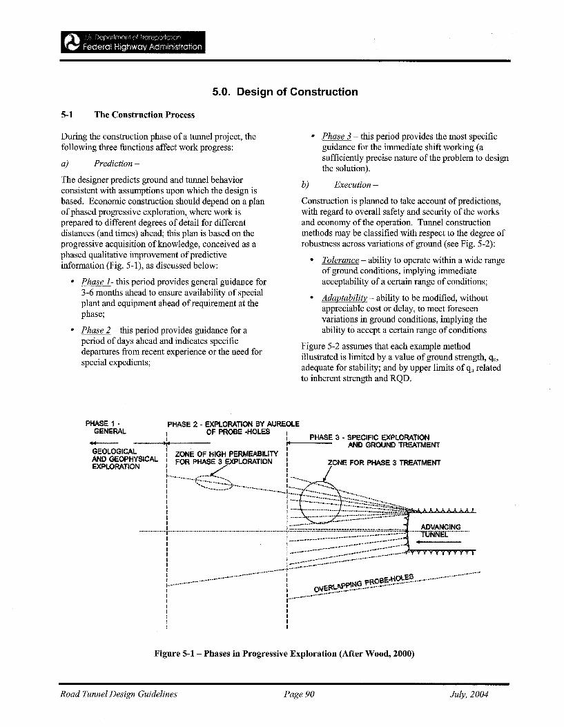
5.0. Design of Construction
5-1 The Construction Process
During the construction phase of a tunnel project, thefollowing three functions affect work progress:
a) Prediction -
The designer predicts ground and tunnel behaviorconsistent with assumptions upon which the design isbased. Economic construction should depend on a planofphased progressive exploration, where work isprepared to different degrees of detail for differentdistances (and times) ahead; this plan is based on theprogressive acquisition of knowledge, conceived as aphased qualitative improvement ofpredictiveinformation (Fig. 5-1), as discussed below:
• Phase 1- this period provides general guidance for3-6 months ahead to ensure availability of specialplant and equipment ahead of requirement at thephase;
• Phase 2 - this period provides guidance for aperiod of days ahead and indicates specificdepartures from recent experience or the need forspecial expedients;
• Phase 3 - this period provides the most specificguidance for the immediate shift working (asufficiently precise nature of the problem to designthe solution).
b) Execution -
Construction is planned to take account ofpredictions,with regard to overall safety and security ofthe worksand economy of the operation. Tunnel constructionmethods may be classified with respect to the degree ofrobustness across variations of ground (see Fig. 5-2):
• Tolerance - ability to operate within a wide rangeofground conditions, implying immediateacceptability of a certain range ofconditions;
• Adaptability - ability to be modified, withoutappreciable cost or delay, to meet foreseenvariations in ground conditions, implying theability to accept a certain range of conditions
Figure 5-2 assumes that each example methodillustrated is limited by a value ofground strength, qu,adequate for stability; and by upper limits of qu relatedto inherent strength and RQD.
GEOLOGICALAND GEOPHYSICALEXPLORATION
PHASE 1 •GENERAL
PHASE 2 • EXPLORATION BY AUREOLE
I OF PROBE -HOLES I PHASE :'3 • SPECIFIC EXPLORATION.:. :;.1---- AND GROUND TREATMENT: ZONE OF HIGH PERMEABILITY :l FOR PHASE 3 EXPLORATION: ZONE FOR PHASE 3 TREATMENT
1"-'(~~~-"-""-!~~~~~~~~~;j,~~i2' -'~...::Io.<l....ll.oll...ll>.oil..L.I ,I_.•._•••••••••••••••_•••_••••_••__~_______ ADVANCING
-·-··r··-···-·-····::~:~::::~:]~;~;.~~~~~~~§~~ ..~:~~~~- ..-I I ""0 ..ROBe.·HO~~-.•.•.•.•._..·~.-.•.'" I O\lER\.APPh.. ':.•.•••.•••.•.••! ~ _ _._ _._ _.I II II II II I
Figure 5-1- Phases in Progressive Exploration (After Wood, 2000)
Road Tunnel Design Guidelines Page 90 July, 2004
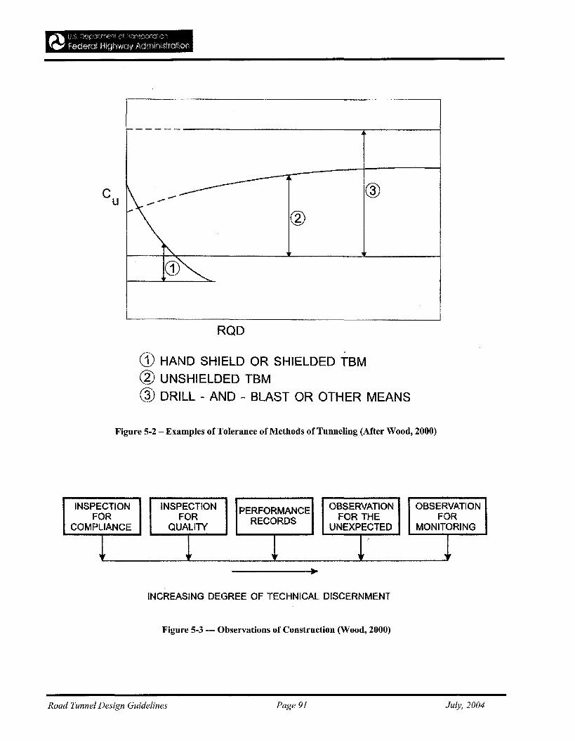
~, tr:~ r)(·J:i'!:trtr~'(-f.l--'i (! ~fons:))lla1}~)n
f~ Federal HighwClv Adml!l,strafiOfl
------
K- @
@
~
CD~
RQD
CD HAND SHIELD OR SHIELDED -rBM@ UNSHIELDED TBM
@ DRILL - AND - BLAST OR OTHER MEANS
Figure 5-2 - Examples of Tolerance of Methods of Tunneling (After Wood, 2000)
INSPECTION INSPECTION PERFORMANCE OBSERVATION OBSERVATIONFOR FOR RECORDS FOR THE FOR
COMPLIANCE QUALITY UNEXPECTED MONITORING.r ,it it ,
INCREASING DEGREE OF TECHNICAL DISCERNMENT
Figure 5-3 --- Observations of Construction (Wood, 2000)
Road Tunnel Design Guidelines Page 91 July, 2004
1.
11.
~~ :... 1) DecJ'(]rtrn(i'fr." .'),~ fr'J("r~)10r"On
f~ federal Highway Adminastraflofi
c) Observation -
Construction inspection, which may include provisionof design data to permit refinement of the initial design(see Fig. 5-3), includes several functions:
Inspection - ascertains that work is conducted incompliance with specifications supplemented by otherparticular requirements, including those arising fromprediction;
Geological Observation - gives advance warning ofunforeseen hazards;
Performance Observation - recording of obviouscharacteristics of defects, and of movements, strains,stresses, groundwater levels, pore water pressures, etc.
5-2 Bidding Strategy
a) General-
A bidding strategy should be prepared, whether or notconstruction is separated contractually from design ofthe project, where competition is based primarily onprice.
Assessment of geological risk should be a centralcomponent of the bidding strategy, and may beapproached in three elements:
Factual infOrmation on geological hazardsavailable to bidders;
Interpretation o[factual data with areas of majoruncertainty identified in relation to engineeringconsequences
iii. Consideration ofthe extent ofthe geological hazardimposed on the bidder by the terms of the contract,giving rise to geological risk when coupled with thepreferred method of construction.
Bidding strategy should bedominated by iii) resulting inthe following risk sharing scenarios:
1. No Risk Sharing - full imposition of geological riskon Contractor, who is expected to takeresponsibility for circumstances incompatible withdata provided by designer(s).
2. Protection ofContractor against 'unfOreseeable'extreme risk - in the absence of an obligation bythe Engineer to reveal his understanding of'foreseeable' at bid time, there remains problems ininterpretation of 'foreseeable' risk.
3. Equitable Risk Sharing - elements of geologicalhazard of major importance to a preferred schemeof construction and to its cost are identified, with
reimbursement based on stated Reference Conditions.The Contractor must be prepared, in turn, to provide,from time to time, details ofhis proposals forundertaking the work in sufficient detail to permitassessments against any particular interests of theOwner which might be affected.
5-3 Choice of Method
a) General-
The choice of method is usually dictated by the degreeof certainty to which potential geologic problems maybe identified and located, and should includeconsideration of the following factors:
• Ground conditions
• Continuous tunnel length ofa particular size;
• Extent of inter-connection between tunnels;
• Useful tunneled space in relation to practicabletunnel profiles;
• Value of time;
• Spacing between tunnels;
• Local experience and maintenance facilities;
• Accessibility ofproject;
• Environmental concerns.
For overall project economy and optimal constructionstrategy, there needs to be clear mutual understanding ofthe significance of the factors listed above.
Details on the possible significance of each of thesefactors are given in Wood (2000).
Road Tunnel Design Guidelines Page 92 July, 2004
,~~ L S !fi~oortrnt)(r" o~ j f ::!t"'SPO"tO:fuy"
'f." fooeral Highway Administration
REFERENCES
AASHTO 1984American Association of State Highway and TransportationOfficials (AASHTO) 1984 Guide for Roadway Lighting,Washington, D.C.
Abramson 1994Abramson, L. W. 1994. Groundwater lowering and drainagetechniques. In Ground Control and Improvement, P.PXanthakos, L. W. Abramson, and D.A. Bruce, eds. NewYork: John Wiley and Sons.
Adrian, W.K.1990Adrian, W.K. 1990 " A Method for the Design of TunnelEntrance Lighting," Journal ofthe Illuminating EngineeringSociety, Winter.
Adrian, W.K.1987Adrian, W.K. 1987 Adaptation Luminance WhenApproaching a Tunnel in Daytime, Lighting Research andTechnology, 19(3),73-79.
Amadei and Pan 1992Amadei, B., and Pan, E. 1992. "Gravitational Stresses inAnisotropic Rock Masses with Inclined Strata," Int. J. RockMech. Min. Sci. & Geomech., Abstr., Vol. 29:225-236.
Amadei, Swolfs, and Savage 1988Amadei, B., Swolfs, H. S., and Savage, W. Z. 1988."Gravity-Induced Stresses in Stratified Rock Masses: RockMechanics and Rock Engineering, 21: 1-20.
American Society of Civil Engineers 1991American Society of Civil Engineers. 1991. "Avoidingand Resolving Disputes during Construction."
American Society of Civil Engineers 1993American Society of Civil Engineers. 1993. "SteelPenstocks" Manual on Engineering Practice No. 79, NY.
American Society of Civil Engineers 1994American Society of Civil Engineers. 1994, "Avoidingand Resolving Disputes during Construction," ASCETechnical Committee on Contracting Practices oftheUnderground Technology Research Council, ASCE, NY.
Amstutz 1970Amstutz, I. E. 1970. "Buckling of Pressure-Shafts andTunnel Linings," Water Power.
Anderson and Richards 1987Anderson, M. G., and Richards, K. S. 1987. SlopeStability - Geotechnical Engineering and Geomorphology.John Wiley and Sons, New York.
Andreis and Valent 1993Andreis, I., and Valent, G. 1993. "Yindaruqin Irrigation
Project: High Speed Tunneling in China;" RETCProceedings: 383-399.
Annett and Stewart 1991Annett, M. F., and Stewart, J. 1991. "Development ofGrouting Methods for Channel Tunnel United KingdomSegmental Liner," Tunneling '91:173-179.
Anonymous 1977Anonymous. 1977. "Precast Segments Line Bored Tunnel,"California Builder & Engineer, September. (Buckskin Mt.Project, Arizona)
Anonymous 1980Anonymous. 1980. "Precast Liner Keeps Diversion Tunnelon Track," Highway & Heavy Construction, June.(park River Diversion Tunnel, Hartford, Connecticut)
ANSIIIES 1987ANSIIIES RP-22 1987 American National Standard Practicefor Tunnel Lighting.
Aristorenus 1992Aristorenus, G. 1992. "Time-Dependent Behavior of TunnelsExcavated in Shale," Ph.D. dissertation, Department ofCivil Engineering, Massachusetts Institute of Technology,Cambridge, MA: 337.
ASHRAE Handbook 1989ASHRAE Handbook. 1989. Fundamentals I-P Edition,American Society of Heating Refrigeration and AirConditioning Engineers, Inc.
ASME Boiler and Pressure Vessel CodeASME Boiler and Pressure Vessel Code, Section VIII,Division 1, Pressure Vessels.
Associated Engineers, JV 1980Associated Engineers, a N of Parsons Brinckerhoff Quade& Douglas, Inc., De Leuw Cather and Company, and KaiserEngineers 1980 Subway Environmental Design Handbook,Volume IL Subway Environment Simulation (SES) ComputerProgram, Version3.0, Part 1: User's Manual, prepared forthe Transportation Systems Center ofU.S.D.O.T.,November.
Associated Engineers, JV 1980Associated Engineers, a Joint Venture of ParsonsBrinckerhoff Quade & Douglas, Inc., De Leuw Cather andCompany and Kaiser Engineers 1976 Subway EnvironmentalDesign Handbook, Volume 1, Principles and Applications,Second Edition, National Infonnation Service No. PB-254788.
Road Tunnel Design Guidelines Page 93 July, 2004
Association Francaise des Travaux en Souterrain 1991Association Francaise des Travaux en Souterrain. 1991."Recommendations on Grouting for Underground Works,"Tunneling and Underground Space Technology, Vol. 6, No.4:383-462
ASTMC 1240ASTM C 1240 "Standard Specification for Silica Fume forUse in Hydraulic Cement Concrete and Mortar."
ASTMA820ASTM A 820 "Standard Specification for Steel Fibers forSteel Fiber-Reinforced Concrete."
ASTM C 1116-91ASTM C 1116-91 "Standard Specification for FiberReinforced Concrete and Shotcrete."
ASTM C 1018-92ASTM C 1018-92 "Standard Test Method for FlexuralToughness and First-Crack Strength of Fiber-ReinforcedConcrete."
Australasian Fire Authorities Council 2001Australasian Fire Authorities Council 2001 "Fire SafetyGuidelinesfor Road Tunnels" AFAC Ltd., Australia.
Baker 1992Baker,W. H., ed. (1992). Grouting in GeotechnicalEngineering. New York: American Society of CivilEngineers.
Bamford 1984Bamford, W. E. 1984. "Rock Test Indices Are BeingSuccessfully Correlated with Tunnel Boring MachinePerformance," Proceedings, 5th Australian TunnelingConference, Melbourne, October, Vol. 2: 19-22.
Barton 1988Barton, N. 1988. "Rock Mass Classification and TunnelReinforcement Selection Using the Q-System," ASTM STP984, Rock Classification Systems for Engineering Purposes.
Barton, Lien, and Lunde 1974Barton, N., Lien, R, and Lunde, 1 1974. "EngineeringClassification of Rock Masses for the Design of TunnelSupport" Rock Mechanics, Vol. 6, No.4.
Bathe 1982Bathe, K-J. 1982. Finite Element Procedures in EngineeringAnalysis. Prentice-Hall: 735.
Beavis 1985Beavis, F. C. 1985. Engineering Geology. BlackwellScientific Publications.
Beldwald 1992Beldwald, P. 1992. "A Contribution to the Design ofTunnels in Argillaceous Rock; Ph.D. dissertation,Department of Civil Engineering, Massachusetts Institute ofTechnology, Cambridge, MA: 427.
Berge, Wang and Bonner 1993Berge, P. A., Wang, H. F., and Bonner, B. P. 1993."Pore Pressure Buildup Coefficient in Synthetic and NaturalSandstones," Int. J Rock Mech. Min. Sci. & Geomech.,Abstr., Vol. 30, No. 7:1135-1141.
Bickel, Kuesel and King 1996Bickel, Kuesel and King, 2nd ed. "Tunnel EngineeringHandbook"; Chapman & Hall, N.Y.
Bieniawski 1979Bieniawski, Z. T. 1979. "The Geomechanics Classificationin Rock Engineering Applications," Proceedings, 4thInternational Congress on Rock Mechanics, ISRM,Montreux. A. A. Balkema, Rotterdam, Vol. 2:41-48.
Blanck 1969Blanck, lAo (1969) The Balboa Outlet Tunnel MonorockPublication.
Blaster's Handbook 1980Blaster's Handbook, 16th ed. 1980. E. I. DuPont deNemours, Wilmington, DE. (Later editions may be available)
Bonilla., Mark, and Lienkaemper. 1984Bonilla, M.G., R K. Mark, and 11 Lienkaemper. (1984).Statistical relations among fault displacement. Bulletin oftheSeismological Society ofAmerica, 74.
Brady, Bhore, Gordon and Honeycutt 1985Brady, 1J. Bhore, 1S., Gordon, RB., and Honeycutt, J.W.1985 "Practical Methods of Shallow Shaft Sinking,"Proceedings ofRapid Excavation and Tunneling Conference,June 16-20, New York.
Brekke and Ripley 1993Brekke, T. L., and Ripley, B. D. 1993. "Design of PressureTunnels and Shafts," Chapter 14 of ComprehensiveRock Engineering - Vol. 2, J. A. Hudson, cd.: 349-369.
British Highway Agency 1999British Highway Agency 1999 "Design ofRoad Tunnels"Design Manual for Roads and Bridges, vol. 2, Section 2 Part9, BD 78/99.
BTS and ICE 2004British Tunnelling Society (BTS) and Institution of CivilEngineers (ICE) 2004; "Tunnel Lining Design Guide",Thomas Telford Ltd., March
Brockenbrough and Johnston 1974Brockenbrough, R.L., and Johnston, B.G. 1974 u.s.s. SteelDesign Manual.
Broms and Bennermark 1967Broms, B.B. and H. Bennermark. (1967). Stability of clay atvertical openings. Journal ofthe Geotechnical Division 3.
Brown 1981Brown, E. T. 1981. "Rock Characterization Testing andMonitoring: ISRM Suggested Methods, published for theCommission on Testing Methods, International Society for
Road Tunnel Design Guidelines Page 94 July, 2004
Rock Mechanics by Pergammon Press.
Brown, Bray, Ladanyi, and Hock 1983Brown, E. T., Bray, J. W., Ladanyi, B., and Hock, E.1983. "Ground Response Curves for Rock Tunnels, Journalof Geotechnical Engineering," Vol. 109, No.1, AmericanSociety ofCivil Engineering.
Cassinelli, Cina, Innaurato, Mancini, Smapaolo 1982Cassinelli, F., Cina, S., Innaurato, N., Mancini, R., andSmapao10, A. 1982. "Power Consumption and MetalWear in Tunnel Boring Machines: Analysis of TunnelBoring Operations in Hard Rock," Proceedings, Tunnelling'82, London, IMM 73-81.
Chabannes 1982Chabannes, C. R. 1982. "An Evaluation of the TimeDependent Behavior of Solution Mined Caverns in Salt forthe Storage ofNatural Gas," M.S. thesis, PennsylvaniaState University.
Cecil (ca. 1970)Cecil, O.S. (ca. 1970) "Site Inspection at TehachapiMountains Crossing of the California Aqueduct, TunnelNo.1, North PortaL"
Chaiken, RE, Singer, J.M., and Lee, C.K. 1979Chaiken, RE, Singer, J.M., and Lee, C.K. 1979 Model CoalTunnel Fires in Ventilation Flow, U. S. Bureau of MinesReport of Investigations, Rl8355.
Cheng, Abousleiman, and Roegiers 1993Cheng, A. H-D., Abous1eiman, Y., and Roegiers, J. C.1993. "Review of Some Poroelastic Effects in RockMechanics," Int. J. Rock Mech. Min. Sci. & Geomech.,Abstr., Vol. 30, No. 7:1119-1126.
CIE 1990Commission Intemationale de I'Eclainage (CIE) 1990 Guidefor the Lighting ofRoad Tunnels and Underpasses,Publication, CIE 53-1990 CIE Central Bureau, Vienna,Austria.
Clayton, Simons, and Matthews 1982Clayton, C. R. I., Simons, N. E., and Matthews, H. C.1982. Site [investigation, A Handbookfor Engineers,Halstead Press.
Cording and Hansmire 1975Cording, E. J., and W. H. Hansmire. (1975). Displacementsaround soft ground tunnels. Proceedings, Fifth PanamericanCongress on Soil Mechanics and Foundation Engineering,Buenos Aires.
Croce, P.A., et al. 1978Croce, P.A., et al. 1978 A Full-Scale Investigation oftheFuel-Load Hazard ofTimber Sets in Mines, Second AnnualReport, No: RC 78-T-6, Factory Mutual ResearchCorporation, Norwood, MA.
Critchfield 1985Critchfield, J. W. 1985. Tunneling in Gassy Ground,"
Proceedings, RETC, New York, AIME: 441-461.
Culverwell 1989Culverwell, D.R. 1989 "Comparative merits of steel andconcrete forms of tunnel," Proceedings of the ImmersedTunnel Techniques Symposium, Manchester, UK.
Cundall 1976Cundall, P. A. 1976. "Explicit Finite Difference Methodsin Geomechanics, Numerical Methods in Engineering,"Proceedings of the EF Conference on Numerical Methodsin Geomechanics, Blacksburg, Virginia. Vol. 1: 132-150.
Cundall and Hart 1993Cundall, P. A., and Hart, R. D. 1993. "Numerical Modelingof Discontinuities" Comprehensive Rock Engineering,Vol. 2, J. A. Hudson, ML, Pergammon Press: 231-243.
Deere 1968Deere, D. U. 1968. "Geologic Considerations," Chapter 1ofRock Mechanics in Engineering Practice, K. G. Staggand O. C. Zienkiewicz, cd., Wiley, New York.
Deere and Deere 1988Deere, D. U., and Deere, D. W. 1988. "The Rock QualityDesignation (RQD) Index in Practice, in Rock ClassificationSystems for Engineering Purposes," L. Kirkaldie, cd.,ASTM 1984.
Deere, Hendron, Patton, and Cording 1967Deere, D. u., Hendron, A. J., Patton, F. D., and Cording,E. J. 1967. "Design of Surface and Near-SurfaceConstruction in Rock, in Failure and Breakage of Rock,"C. Fairhurst, cd., Society of Mining Engineers of AIME,New York.
Deere, Peck, Monsees, and Schmidt 1969Deere, D. U., Peck, R. B., Monsees, J. E., and Schmidt, B.1969. "Design of Tunnel Liners and Support Systems,"Report to UMTA, DOT, available through NTIS.
Deere, Peck, Parker, Monsees, and Schmidt 1970Deere, D. U., Peck, R. B., Parker, H. W., Monsees, J. E.,and Schmidt, B. 1970. "Design of Tunnel Support Systems":Highway Res. Rec. No. 339:26-33.
Deix and Braun. 1987Deix, E, and B. Braun. (1987). The use ofNATM incombination with compressed air and ground freezing duringVienna subway construction. Proceedings, Rapid Excavationand Tunneling Conference, Littleton, CO: Society ofMiningEngineers Inc.
Dijon and Winkin 1990Dijon J.M., and Winkin, PH. 1990 Tunnel Lighting.Symmetrical, Counter Bean and Pro Beam-Comparison andTests, Symposium and Visibility, National Research Council,Washington, D.C., July.
Road Tunnel Design Guidelines Page 95 July, 2004
Dolcini, Grandori, and Marconi 1990Do1cini, G., Grandori, R., and Marconi, M. 1990. "WaterSupply Revamp for Bogota: Tunnels & Tunnelling,September, 22(9): 33-38. (Los Resales Water Tunnel)
Dowding 1985Dowding, C. H. 1985. Blast Vibration Monitoring andControl, Prentice Hall.
Dunniciiff, 1988Dunnicliff, J. 1988. Geotechnical Instrumentation forMonitoring Field Peiformance, Wiley, New York: 577.
Einstein 1989Einstein, H.H. 1989. Design and analysis ofundergroundstructures in swelling and squeezing rocks (Chapter 6). InUnderground Structures-Design and Instrumentation, RS.Sinha, ed. New York: Elsevier.
Electric Power Research Institute (EPRI) 1987Electric Power Research Institute (EPRI). 1987. "DesignGuidelines for Pressure Tunnels and Shafts," Palo Alto,California.
Engels, Cahill, and Blackey 1981Engels, J. G., Cahill, J. T., and Blackey, E. A., Jr. 1981."Geotechnical Performance of a Large Machine-BoredPrecast Concrete Lined Tunnel," 1981 RETC Proceedings:1510-1533. (Park River Diversion Tunnel, Hartford,Connecticut)
Eusebio, GrasSo, Mahtab, and Innaurato 1991Eusebio, A., Grasso, P., Mahtab, A., and Innaurato, A.1991. "Rock Characterization for Selection ofa TBM fora Railway Tunnel near Geneva, Italy," Proceedings, Int.Symp. on Mine Mech. and Automation, CSMIUSBM,Vol. 1:4-25 to 4-35.
Farmer 1%8Farmer, I. W. 1968. Engineering Properties ofRocks,SponLtd.
Farmer and Glossop 1980Farmer, I. W., and Glossop, N. H. 1980. "Mechanics ofDisc Cutter Penetration," Tunnels and Tunnelling, Vol. 12,No. 622-25.
Faucett 1969Faucett, .E. 1969 "The Zonal Cavity System Applied toTunnels," Illuminating Engineering Society NationalConference, August.
Federal Highway AdministrationFederal Highway Administration "Prevention and Control ofHighway Tunnel Fires" FHWA-RD-83-032.
Fernandez and Alvarez 1994Fernandez, G., and Alvarez, T. A. 1994. "SeepageInduced Effective Stresses and Water Pressures aroundPressure Tunnels," Journal ofGeotechnical Engineering,American Society of Civil Engineers.
Fezlmyr, A.H.1976Fezlmyr, A.H. 1976 "Research in Austria on tunnel fire,"BHRA, Second International Symposium on theAerodynamics and Ventilation of Vehicle Tunnels, March23-25, Paper 12, Cambridge, England.
FIP 1986FIP. 1986. Corrosion and Corrosion Protection ofPrestressed Ground Anchorages, Thomas Telford Ltd.
Fliigge 1960Fliigge, W. 1960. Stresses in Shells, Springer-Verlag,Berlin.
Garshol1983Garshol, K. 1983. Excavation support and pre-grouting ofTBM-driven sewer tunnel, Norwegian TunnellingTechnology Publication No.2, Tapir.
Goldberg, Jaworsky and Gordon 1976Goldberg, D.T., W.E. Jaworsky, and M.P. Gordon 1976Lateral Support Systems and Underpinning, U.S.Department of Transportation, Report No. FWHA-RD-75128, Vo. I, April, 1976.
Goodman and Shi 1985Goodman, R. E., and Shi, G. H. 1985. Block Theory andits Application to Rock Engineering, Prentice-Hall, NewJersey.
Goodman 1995Goodman, RE. 1995. Block theory and its applications-the1995 Rankine Lecture. Geotechnique. In press.
Graham 1976Graham, P. C. 1976. "Rock Exploration for MachineManufacturers," in Exploration for Rock Engineering,Proceedings of the Symposium, Johannesburg, Z. T.Bieniawski, cd., Balkema, Vol. 1: 173-180.
Grandori, Dolcini, and Antonini 1991Grandori, R, Do1cini, G., and Antonini, F. 1991. "TheResales Water Tunnel in Bogota," Proceedings, RapidExcavation and Tunneling Conference, Seattle: 561-581.
Greuer 1973Greuer, RE. 1973 Influence ofMine Fires on the VentilationofUnderground Mines, U.S. Bureau of Mines Open FireReport 74-73, July (NTIS: PB-225-834).
Groseclose and Schoeman 1987Groseclose, W. R., and Schoeman, K. D. 1987. "PrecastSegment Lining for Buckskin Mountains Water ConveyanceTunnel," R. J. Robbins and R J. Conlon, cd., 1976RETC Proceedings, Las Vegas, Nevada: 448-463.
Grant, Christian, and Vanmarke 1981Grant, R, J. T. Christian, and E. H. Vanmarke (1981).Differential settlement of buildings, Journal ofGeotechnicalEngineering, 107, American Society of Civil Engineers.
Road Tunnel Design Guidelines Page 96 July, 2004
Greuer 1977Greuer, RE. 1977 Study ofMine Fires. Part 1. ComputerSimulation ofVentilation Systems Under the Influence ofMine Fires, U.S. Bureau of Mines Open File Report 115(1)78, October (NTIS: PB 2882311AS).
Gularte, Taylor, Monsees and Whyte 1991Gularte, Taylor, Monsees and Whyte 1991, "Tunnelingperformance of chemically grouted alluvium landfill - LosAngeles Metro Rail Contract A-130, Proceedings, RapidExcavation and Tunneling Conference, Littleton, CO Societyof Mining Engineers, Inc..
Gularte 1982Gularte, F. B. (1982). Grouting Practice for Shafts, Tunnels,and Underground Excavations", Short Course Notes,University of Wisconsin-Milwaukee.
Gularte 1989Gularte, F. B. (1989). Grouting Practice for Shafts, Tunnels,and Underground Excavations", Short Course Notes,University of Wisconsin-Milwaukee.
Hammond 1959Hammond, R 1959 Tunnel Engineering. Macmillan, NewYork.
Harris 1983Harris, F.C 1983 Ground Engineering Equipment andMethods, McGraw-Hill, New York.
Hartmann, Mutmansky, and Wang 1982Hartmann, H. L., Mutmansky, 1 M., and Wang, Y. 1., ed.1982. Mine Ventilation and Air Conditioning, 2nd. Ed.,Wiley.
Hashash and Cook 1994Hashash, Y M. A., and Cook, R. F. 1994. "EffectiveStress Analysis of Supercollider Tunnels," 8th Int. Con!Assoc. Compo Methods and Advances in Rock Mechanics,Morgantown, West Virginia.
Hatzor and Goodman 1993Hatzor, Y, and Goodman, R E. 1993. "Determination ofthe 'Design Block' for Tunnel Supports in Highly JointedRock Comprehensive Rock Engineering, Vol. 2, 1 A.Hudson, cd., Pergammon Press: 263-292.
Havers and Stubbs 1971Havers, lA., and Stubbs, F.W. JR. 1971 Handbook ofHeavyConstruction. McGraw-Hill, New York.
Hemphill 1990Hemphill, G. B. 1990. "Mechanical Excavation System:Selection, Design, and Performance in Weak Reek; Ph.D.dissertation, University ofIdaho, Moscow: 361.
Heselden 1976Hese1den, A.J.M. 1976 "Studies of fire and smoke behaviourrelevant to tunnels," BHRA, Second InternationalSymposium on the Aerodynamics and Ventilation ofVehicleTunnels, March 23-25, Paper 11, Cambridge, England.
Heuer and Virgens 1987Heuer, RE., and D. L. Virgens. (1987). Anticipated behaviorof silty sands in tunneling. Proceedings, Rapid Excavationand Tunneling Conference, Littleton, co: Society of MiningEngineers, Inc.
Heuer 1974Heuer, R.E. (1974). Important ground parameters in softground tunneling. Proceedings ofSpecialty Conference onSubsurface Exploration for Underground Excavation andHeavy Construction, New York: ASCE.
Hitachi Zosen 1984Hitachi Zosen 1984. Hitachi Zosen's Shield TunnelingMachines, Company Brochure, Tokyo.
Hitachi Zosen 1984Hitachi Zosen 1981. "Shield Tunneling Machines",Company Brochure, Tokyo.
Hoeking 1978Hocking, G. 1978. "Stresses around Tunnel Intersections,"in Computer Methods in Tunnel Design, Institution of CivilEngineers: 41-59.
Hock and Brown 1980Hoek, G. E., and Brown, E. T. 1980. "UndergroundExcavations in Rock," Institution ofMining and Metallurgy,London, England: 527.
Hoek and Brown 1988Hoek, G E., and Brown, E. T. 1988. "The Hoek-BrownFailure Criterion - A 1988 Update: Proceedings, 15thCanadian Rock Mech. Symposium, Toronto: 3-38.
Hughes 1986Hughes, H. M. 1986. 'The Relative Cuttability of CoalMeasures Rock," Mining Science and Technology, Vol. 3:95-109.
Huval 1969Huval, C. 1 1969. "Hydraulic Design of Unlined RockTunnels," Journal ofthe Hydraulics Division, Proceedingsofthe American Society of Civil Engineers, Vol. HY4.
Hwang and Chaiken 1987Hwang, C.C., and Chaiken, RE 1987 Effect ofDuct Fire onthe Ventilation Air Velocity, U.S. Bureau of Mines Report ofInvestigation No. 8311.
IES 1990Illuminating Engineering Society 1990 lES LightingHandbook, New York.
lID 2003Ishikawajima-Harima Heavy Industries Co. Ltd. (IHI), 2003"PR Documents ofIHI's Shield Machine", Tokyo, Japan.
International Tunneling Association 1997International Tunneling Association 1997 Immersed andFloating Tunnels State of the Art Report, Working Group
Road Tunnel Design Guidelines Page 97 July, 2004
No. 11., Tunneling and Underground Space Technology,Pergamon Press, Vol. 12, No.2 (April).
IRSInternal Revenue Service Regulations, 26 CFR 181Commerce in Explosives, Washington, DC.
ISRM 1982ISRM. 1982. International Society for Rock Mechanics,ISRM Suggested Methods: Rock Characterization, Testingand Monitoring (E. T. Brown, cd.), Pergammon Press,Oxford.
ITASCA 1992ITASCA. 1992. Fast Lagrangian Analysis ofContinua,Version 3.2, User's Manual, Vol. III.
Jackson 1983Jackson, L.E. 1983 "Serious tunnel fIres with emphasis onthe Caldecott Tunnel fIre, Oakland, California, April 7,1982," presented to the Transportation Research BoardCommittee A2604, Tunnels and Underground Structures,January 29.
Jacobsen 1974Jacobsen, S. 1974. "Buckling of Circular Rings andCylindrical Tubes under External Pressure," Water Power.
Jaeger 1964Jaeger, J. C. 1964. Elasticity, Fracture and Flow withEngineering and Geological Applications, Chapman &Hall, London.
JSCE 1996Japanese Society of Civil Engineers (JSCE) 1996 "JapaneseStandard for Shield Tunneling" Working Group for ShieldTunneling; Subcommittee on English Edition of the JapaneseStandard for Tunneling.
Jessberger 1979Jessberger, H.L. 1979 Ground Freezing, Developments inGeotechnical Engineering, Vol. 26. Elsevier ScientifIcPublishing Company, New York.
Judd and Huber 1961Judd, W. R., and Huber, C. 1961. Correlation ofRockProperties by Statistical Means, International Society onMining Research, G. Clarke, cd., Pergammon, Oxford.
Jumikis 1971Jumikis, A.R. 1971 Foundation Engineering. Intext,Scranton, Pa.
Karlsson and Fryk 1963Karlsson, L., and Fryk, J.O. (1963) "Lining for the IntakeWater Tunnel of the Holjes Hydroelectric Plant in Sweden,"Hochund Tiefbau, Vol. 50.
Karol 1990Karol, R. H. 1990. Chemical Grouting, second edition, NewYork: Marcel Dekker, Inc.
Kawamura et at. 1976Kawamura, H., et al. 1976 "Study on a new ventilationsystem to effectively eliminate fIre smoke in a tunnel,"BHRA, Second International Symposium on theAerodynamics and Ventilation of Vehicle Tunnels, March23-25, Cambridge, England.
Keifer 1966Keifer, O. (1966) Multiple Layer Shotcrete Lining. ACIPublications, SP-14.
Kessler and Moore 1999Kessler, P.N and Moore, C.J. 1999; "Tunneling by TunnelBoring Machine (TBM)".
Ketvertis 1971Ketvertis, A. 1971 Foundation of Canada Engineering Corps.
Ketvertis 1989Ketvertis, A. 1989 "Directional Light Application inVehicular Tunnel Illumination Design," IlluminatingEngineering Society National Conference, 1989.
Korbin 1979Korbin, G. E. 1979. "Factors Influencing the Performanceof Full-Face Hard Rock Tunnel Boring Machines," Reportto USDOT, UMTA-CA-06-0l22-79- 1.
Kuesel1986Kuesel, T. 1986 "Immersed Tube Tunnels: Concept Designand Construction, " Civil Engineering Practice, BostonSociety of Civil Engineers, Spring.
Kuesel1969Kuesel, T. R. 1969. Earthquake design criteria for subways.Journal ofthe Structural Division, 95, ST6.
Lama and Vntukuri 1978Lam~ R. D., and Vutukuri, V. S. 1978. Handbook onMechanical Properties ofRocks, Vol. II, Trans Tech Pub!.,Switzerland.
Lane and Garfield 1972Lane, K., and GarfIeld, L.A. 1972 Proceedings ofFirstNorth American Rapid Excavation and TunnelingConference, Chicago, Illinois, June 5-7,1972. Port CityPress, Baltimore.
Lang 1961Lang, T. A. 1961. "Theory and Practice of Rock bolting,"Trans. Amer. Inst. Mining Engrs., Vol. 220 333-348.
Lang and Bischoff 1982Lang, T. A., and Bischoff, J. A. 1982. "Stabilization ofRock Excavations Using Rock Reinforcement," Proceedings,23rd u.s. Symposium on Rock Mechanics, AIME,New York: 935-944.
Langefors and Kihlstrom 1978Langefors, V., and Kihlstrom, B. 1978. The ModernTechnique ofRock Blasting, Halsted Press, a division ofWiley.
Road Tunnel Design Guidelines Page 98 July, 2004
Lauffer 1958Lauffer, H. 1958. Gebirgsklassljizierungfur den Stollenbau,Geologic und Bauwesen, Vol. 24, No. 1:46-51.
Lawrence 1982Lawrence, DLl (1982) "Shotcrete Lining for a TunnelRequiring Ground Freezing for Initial Support," ShotcreteIV, pp. 155-170.
Lee, Chaiken and Singer 1979bLee, C.K., Chaiken, R.E, and Singer, lM. 1979b "Interactionbetween duct fires and ventilation flow: An experimentalstudy," Combustion Science and Technology 20,59-72.
Lee, Singer and Chaiken 1979aLee, C.K., Singer, J.M., and Chaiken, RE 1979a "Influenceof passageway fires on ventilation flows," SecondInternational Mine Ventilation Congress, Reno, Nevada,November 4-8.
Leonards 1962Leonards, G. 1962 Foundation Engineering. McGraw-Hill,New York.
Little 1989Little, T. E. 1989. "Construction and Performance ofaLarge Diameter Test Chamber in Shale," Proceedings,International Tunneling Association Meeting, Toronto:869-876.
Lo and Yuen 1981Lo, A. Y, and Yuen, C. M. K. 1981. "Design of TunnelLining in Rock for Long-term Time Effect," Can. Geotech.J. Vol. 18: 24-39.
Maidl and Handke 1993Maidl, B., and Handke, D. 1993. "Overcoming a Collapsein the Karawanken Tunnel," Tunnels and Tunnelling:30-32.
Mason 1968Mason, RE. (1968)"The Function of Shotcrete in Supportand Lining in the Vancouver R.R. Tunnel," Tunnel and ShaftCOriference, University of Minnesota.
Matsumoto 1991Matsumoto, Y. and Nishioka, T. 1991 "Theoretical TunnelMechanics" University of Tokyo Press.
Mayo, Adair and Jenny 1968Mayo, R.S., Adair, T., and Jenny, RI. 1968 Tunneling: TheState ofthe Art. U.S. Department of Housing and UrbanDevelopment.
Megaw and Bartlett 1982Megaw, T.M. and Bartlett, J.V. 1982, Tunnels: Planning,Design, Construction, vol. 2. Ellis Horwood Ltd., WestSussex, England.
McCusker 1982McCusker, T.G. 1982. Soft ground tunneling. Chapter 5 inTunnel Engineering Handbook, lO. Bickel and T. R Kuesel,eds., New York: Van Hostrand Reinhold.
McFeat-Smith and Askildsrud 1993McFeat-Smith, I., and Askildsrud, O. G. 1993. "TunnelBoring Machine in Hong Kong," RETC Proceedings:401413.
McWilliams and Erickson 1960McWilliams, lR., and Erickson, E.G. 1960 Methods andCost ofShaft Sinking in the Coeur D'Alene District,Shoshone County, Idaho.U.S. Department ofInterior.
Merritt 1968Merritt, F.S. 1968 Standard Handbookfor Civil Engineers.McGraw-Hill, New York.
Metro Rail Transit Consultants 1984Metro Rail Transit Consultants 1984. Supplemental Criteriafor Seismic Design of Underground Structures, SCRTD, LosAngeles.
Mindlin 1939Mindlin, R. D. 1939. "Stress Distribution around a Tunnel",American Society ofCivil Engineers, New York.
Miner and Hendricks 1969Miner, G.M., and Hendricks RS. (1969) "Shotcreting atHecla Mining," Rapid Excavation Symposium, Sacramento,California.
Mitchell J. K. 1981Mitchell, 1 K. 1981. State-of-the-art report on soilimprovement, Tenth International Conference on SoilMechanics and Foundation Engineering, Stockholm.
Mitchell and Villet 1987Mitchell, lK, and CB. Villet 1987 Reinforcement ofEarthSlopes and Embankments, Transportation Research Board,NCHRP Report 290.
Mizutani 1982Mizutani, T. 1982 Experiment ofVehicular Tunnel Fires,Office of Highway Tunnel Research, Inst. of Civil Eng.Research, Department of Construction, Japan, February.
Monsees and Merritt 1991Monsees, 1. E., and 1 L. Merritt 1991. Earthquakeconsiderations in design of the Los Angeles Metro, inLifeline Earthquake Engineering, M.A. Cassuro, ed., NewYork: ASCE.
Moore 1960Moore, E. T. 1960. "Designing Steel Tunnel Liners forHydro Plants," Hydro Review.
Morgan 1991Morgan, D. R 1991. "Steel Fiber Reinforced Shotcretefor Support ofUnderground Openings in Canada," ConcreteInternational, Nov: 56-64.
Road Tunnel Design Guidelines Page 99 July, 2004
..... iJ,S l)s':lClltrr;Elfl' () ~ru'l";::');1(,1kYI
r~ Fe-dera! Highway AalnlnlStratioo
National Association of Corrosion EngineersInternational 1988National Association of Corrosion Engineers International.1988. Reconunended Practice, Control of External Corrosionof Submerged Metallic Piping Systems (RP-O1-69).
National Public Works Department 1993National Public Works Department 1993 "UndergroundTransport Connections (Rijkswaterstuat). "
NAVFAC 1974NAVFAC 1974 Design Manual-Soil Mechanics,Foundations, and Earth Structures, NAVFAC DM-7, U.S.NavaL Publications and Forms Center, March, Change 2.
Nelson 1993Nelson, P. P. 1993. "TBM Performance with Referenceto Rock Properties," Chapter 10, Vol. 4, ComprehensiveRock Engineering, 1 A. Hudson, cd., Pergammon Press:261-291.
Nelson 1983Nelson, P. P. 1983. "Tunnel Boring Machine Performancein Sedimentary Rocks," Ph.D. dissertation, CornellUniversity: 448.
New York State Industrial Code, Albany, NY.
New Jersey Department ofLabor and Industry, SafetyRegulations, Trenton, N1
NFPA1990National Fire Protection Association (NFPA) 1990 StandardNFPA 130 "Fixed Guideway Transit Systems n.
NFPA2001National Fire Protection Association (NFPA) 2001 StandardNFPA 502 "Standardfor Road Tunnels, Bridges and OtherLimited Access Highways".
NTH (Norwegian Institute of Technology) 1988NTH (Norwegian Institute of Technology). 1988. "HardReek Tunnel Boring: Project Report 1-88, Trondheim,Norway 183.
Nyman et al. 1984Nyman, D. 1, et al. 1984. Guidelinesfor the seismic designofoil and gas pipeline systems. ASCE Technical Council onLifeline Earthquake Engineering, New York: ASCE.
Obert and Duvall 1967Obert, Z L., and Duvall, W. I. 1967. Rock Mechanics andthe Design ofStructures in Rock, John Wiley and Sons.
Occupational Safety and Health Administration, Safety andHealth Standards, Washington, DC.
[Offenegg Tunnel] 1965[Offenegg Tunnel] 1965 Final Report ofthe Tests on theOffenegg Tunnel from May 17-31, 1965, Commission forSafety Measures in Road Tunnels. (Two Volumes-InGerman)
Oriard 1982Oriard, L. L. 1982. Blasting Effects and Their Control, inUnderground Mining Methods Handbook, Hustrulid, cd.,AIME, Denver, CO.
O'Rourke 1984O'Rourke, T.D. 1984 "Guidelines for Tunnel Lining Design"ASCE 1984.
Ozdemir and Wang 1979Ozdemir, L., and Wang, F. 1979. "Mechanical TunnelBoring, Prediction, and Machine Design," Final ReportNSFIRA-790161: 204.
Palmer and Belshaw 1980Palmer, 1H.L., and D. 1 Belshaw, (1980). Deformations andpore pressures in the vicinity of a precast, segmented,concrete lined tunnel in clay. Canadian GeotechnicalJournal, 17.
Palmer and Belshaw 1979Palmer, 1.H.L., and D. 1. Belshaw 1979. Long-termperformance of a machine-bored tunnel with use of anunreinforced, precast segmented concrete lining in soft clay,Proceedings Tunnel '79, London: Institution of Mining andMetallurgy.
Pan and Amadei 1993Pan, E., and Amadei, B. 1993. "Gravitational Stresses inLong Asynunetric Ridges and Valleys in AnisotropicReek," Int. J Rock Mech. Min. Sci. & Geomech., Abstr.,Vol. 30 No.7: 1005-1008.
Paris 1921Paris, J.M. 1921 "Stress coefficients for large horizontalpipes," Engineering News Record, 87(19) (November 10).
Pariseau 1993Pariseau, W. G. 1993. "Equivalent Properties ofa JointedBlock Material," [Int. J. Rock Mech. Min. Sci. & Geomech.,Abstr., V01.30, No.7: 1151-1157.
Peck 1969Peck, R B. 1969. Deep excavations and tunneling in softground. State-of-the Art Volume, Seventh InternationalConference on Soil Mechanics and Foundations, MexicoCity.
Peck 1973Peck, R. B. 1973. "Influence ofNon-technical Factors onthe Quality of Embankment Dams, Embankment DamEngineering", Casagrande Vol., Wiley, New York: 201-208.Reprinted in Judgment in Geotechnical Engineering: TheProfessional Legacy ofRalph B. Peck, J. Dunnicliff andD. U. Deere, cd., 1984. Wiley, New York: 137-144.
Peck 1984Peck, R. B. 1984. "Observation and Instrumentation,Some Elementary Considerations," Postscript, in Judgmentin Geotechnical Engineering: The Professional Legacy ofRalph B. Peck, J. Dunnicliff and D. U. Deere, cd., 1984.Wiley, New York: 128-130.
Road Tunnel Design Guidelines Page 100 July, 2004
Peck 1988Peck, R B. 1988. Foreword to Geotechnical[instrumentation for Monitoring Field Performance, by JohnDunnicliff,Wiley, New York: vii-ix.
Pender 1980Pender, M. J. 1980. "Elastic Solutions for a Deep CircularTunnel," Geotechnique.
Permanent International Association of RoadCongress(PIARC) 1987 PIARC report.
Persson, Hoimberg, and Lee 1993Persson, P. A., Holmberg, R, and Lee, J. 1993. RockBlasting and Explosives Engineering, CRC Press.
Peterson, Nelson, Nelson, and Wagener 1991Peterson, DL, C.R Nelson, B.K. Nelson, and B.D. Wagener.1991. Design and construction of the Lafayette Bluff Tunnel,Proceedings RETC, Seattle.
Phienwaja.1987Phienwaja, N. (1987). Ground response and supportperformance in a sheared shale, Stillwater Tunnel, Utah,Ph.D. Thesis, University of Illinois at Urbana-Champaign.
Phien-Wej and Cording 1991Phien-Wej, N., and EJ. Cording. 1991. Sheared ShaleResponse to Deep TBM Excavation. New York: Elsevier.
Polshin and Tokar 1957Polshin, D.E., and Tokar, RA. (1957). Maximum allowablenon-uniform settlement of structures. Proceedings 4thInternational Conference on Soil Mechanics and FoundationEngineering, Vol. I, London.
Pona, Civil Consulting, Inc.Pona, Civil Consulting, Inc., Sacramento, CA - "MathCadApplications for Determination of the Tunnel Steel LinerCritical Buckling Pressure."
Powers 1992Powers, J. P. (1992). Construction Dewatering-New Methodsand Applications, Second Edition, New York: John Wileyand Sons.
Powers 1981Powers, J. P., Construction Dewatering-A Guide to Theoryand Practice, John Wiley and Sons, New York, 1981.
Powers 1972Powers, J.P. 1972 "Groundwater Control in TunnelConstruction," Proceedings ofNorth American RapidExcavation and Tunneling Conference, ASCE-AIME, NewYork.
Proctor and White 1977Proctor, R.Y. and T. L. White (1977). Earth Tunneling withSteel Supports, Commercial Shearing, Inc., Youngstown,OH.
Procter and White 1946Procter, R. V., and White, T. L. 1946. "Rock Tunnelingwith Steel Supports", The Commercial Shearing andStamping Company, Ohio 1946, revised 1968, copyright1946 by The Commercial Shearing and Stamping Company.
Quadrio (ca. 1964)Quadrio, C.P. (ca. 1964) "New Methods for the Constructionof Tunnels," II Monitire Tecnico, Vol. 1.
Rabcewicz 1964Rabcewicz, L.V. (1964) "The New Austrian TunnelingMethod," Water Power.
Rarjeat 1991Rarjeat, P. E. (1991). Evolution of tunneling methods inMexico during last 20 years. Proceedings, Rapid Excavationand Tunneling Conference, Littleton, CO: Society of MiningEngineers, Inc.
Rasmussen and Ronhild 1990Rasmussen, N., and Ronhild, C.J. 1990 "Settlement ofimmersed CN tunnels," Proceedings ofthe SecondSymposium on Strait Crossings, Norway.
Richardson and Mayo 1941Richardson, H. W., and RS. Mayo (1941) Practical TunnelDriving. New York: McGraw Hill.
Riley 1964Riley, W. F. 1964. "Stresses at Tunnel Intersections,"Journal ofthe Mechanics Division, proceedings oftheAmerican Society ofCivil Engineers.
Romero 2002Romero, V. 2002 "NATM in Soft Ground, a Contradiction ofTerms?" World Tunnelling pp 338-342. September.
Ropkins 1998Ropkins J.W.T. 1998. "Jacked Box Tunnel Design"Proc Geo-Congress 98, Boston, ASCE Jacked Tunnel Design& Construction" pp 21-38
Roark and Young 1975Roark, RJ., and Young,W.C. 1975 Formulasfor Stress andStrain, Fifth Edition, McGraw-Hill, New York.
Rotter 1960Rotter, E. (1960) "Spiritzbeton und seine praktischeAndwending, im Untertagebau," Symposium at Lesben,Austria.
Roxborough and Phillips 1975Roxborough, F. F., and Phillips, H. R. 1975. "RockExcavation by Disc Cutter," Int. J. Rock Mech. Min. Sci.,Vol. 12, No. 12: 361-366.
Royal Institution of Engineers and The NetherlandsTunnels 1987Royal Institution of Engineers and The Netherlands Tunnels1987 Immersed Tunnels Proceedings of Delta TunnelingSymposium, Amsterdam, November.
Road Tunnel Design Guidelines Page 101 July, 2004
~"' l! S OeC<J\trilOi" (! Iransp:)I1ar;<)l1
f~ Federal Hlgnwav Adrr'l!ll"liStrCltlOn
Salencon 1969Salencon. 1969. "Contraction Quasi-Statique d'une CaviteSymetrique, Spherique ou Cylindrique dans un MilieuElasto-plastique; Annales des Ponts et Chaussees, Vol. 4:231-236.
Sanchez-Trejo 1985Sanchez-Trejo, R. 1985. "Comparative Solutions ofShotcrete and Conventional Concrete Permanent Linings forWater Supply Tunnels", Shotcretefor Underground SupportIV, Selected Papers from Conference, held in Paipa,Colombia, September 5-10, 1982, Published by EngineeringFoundation, New York.
Schmidt 1979Schmidt, B. (1979). Settlements and ground movementsassociated with tunneling in soil. Ph.D. Thesis, University ofIllinois.
Schmidt and Grantz 1979Schmidt, B., and Grantz, W. 1979 "Settlement of immersedtunnels," Journal ofthe Geotechnical Division, ASCE,September.
Schmitter and Morens 1983Schmitter, 1, and Morens, O. 1983. "Tunnel conDeformaciones Excesivas," The Pan-american Coriferenceon Soil Mech., Vancouver, B.C.
Schnabel Foundation Company 1982Schnabel Foundation Company 1982 Tiebacks, U.S.Department of Transportation, Report No. FWHAlFD82/047, July.
Schnabel 1982Schnabel, H. 1982 Tiebacks in Foundation Engineering andConstruction, McGraw-Hill, New York.
Schoeman 1987Schoeman, K. D. 1987. "Buckskin Mountains Tunnel andStillwater Tunnel: Developments in Technology." Tunnellingand Underground Transport. Future Developments inTechnology, Economics, and Policy. F. P. Davidson, cd.,Elsevier, New York 92-108.
Schorer 1933Schorer, H. 1933 "Design oflarge pipe lines," Trans. ASCE98.
Schreuder 1964Schreuder, A. (1964) The Lighting ofVehicular Tunnels,Phillips Technical Library, Eindhoven, The Netherlands.
Schwartz, Azzouz, and Einstein 1980Schwartz, C. W., Azzouz, A. S., and Einstein, H. H. 1980."Improved Design of Tunnel Supports," U.S. Departmentof Transportation, Report No. UMTA-MA-06-0100-8 0-5.
Senthivel 1994Senthivel,A. 1994. Report to the Board of Consultants for theYacambu-Quibor Transfer Tunnel, November.
Serafin and Pereira 1983Serafin, J. L., and Pereira, J. P. 1983. "Consideration ofthe Geomechanics Classification of Bieniawski,"Proceedings, Int. Symp. on Exploration for RockEngineering.
Sharp and Lawrence 1982Sharp, lC. and Lawrence, D.Ll (1982) "Final ShotcreteLinings for an Underground Power Station in ArgillaceousRocks," Shotcrete IV, pp. 115-154.
Sharp and Ozdemir 1991Sharp, W., and L. Ozdemir. 1991. "Computer Modelingfor TBM Performance Prediction and Optimization,"Proceedings, Int. Symp. on Mine Mechanization andAutomation, CSM/USBM, Vol. 1:4-57 to 4-66.
Shotcrete for Ground Support 1976Shotcrete for Ground Support (1976) Proceedings oftheEngineering Foundation Coriference, Easton, Maryland(October), ACI Publication SP-54. American Society ofCivil Engineers and American Concrete Institute.
Shotcrete for Rock Support 1992Shotcrete for Rock Support (1992) Guidelines andRecommendations- A Compilation, Draft Document (E.Malmberg), February, for the ITA WG Shotcrete Use.
Shotcrete for Underground Support III 1978Shotcrete for Underground Support III (1978) Paperspresented at the 1978 Engineering Foundation Conference,St. Anton am Arlberg, Austria (April). EngineeringFoundation, New York.
Shotcrete for Underground Support IV 1982Shotcrete for Underground Support IV (1982) Selectedpapers presented at the 1982 Engineering FoundationConference, Paipa, Boyaca, Colombia (September).Engineering Foundation, New York.
Shotcrete for Underground Support V 1990Shotcrete for Underground Support V (1990) Proceedings ofthe Engineering Foundation Conference, Uppsala, Sweden(June). American Society of Civil Engineers, New York.
Shotcrete for Underground Support VI 1993Shotcrete for Underground Support VI (1993) Proceedingsof the Engineering Foundation Conference, Niagara-on-theLake, Canada (May). American Society of Civil Engineers,New York.
Shotcrete for Underground Support VII 1995Shotcrete for Underground Support VII (1995) Proceedingsof the Engineering Foundation Conference, Seefeld, Austria(June).
Shuster 1985Shuster,lA. 1985 "Ground Freezing for Soft Ground ShaftSinking," Proceedings ofRapid Excavation and TunnelingConference, June 16-20, New York.
Road Tunnel Design Guidelines Page 102 July, 2004
Siskind, Stagg, Kopp, and Dowding 1980Siskind, D. E., Stagg, M. S., Kopp, 1 W., and Dowding,C. H. 1980. "Structure Response and Damage Producedby Ground Vibration from Surface Mine Blasting," U.S.Bureau of Mines, Report of Investigation 8507.
Skempton and MacDonald 1956Skempton, A.W., and D. R. MacDonald. 1956. Theallowable settlements ofbuildings. Proceedings, Institute ofCivil Engineers, Part Ill, London.
Skinner 1988Skinner, E. R. 1988. "A Ground Support Prediction Concept:The Rock Structure Rating (RSR) Model," ASTMSTP 984, L. Kirkaldie, ed.
Sloan 1981Sloan, S. 1981. "Numerical Analysis ofIncompressibleand Plastic Solids Using Finite Elements," Ph.D.dissertation, Trinity College, Cambridge University, UnitedKingdom.
SME Mining Engineering Handbook 1992SME Mining Engineering Handbook. 1992. Second Edition.H. L. Hartman, Senior Editor, Society ofMiningEngineers.
Stack 1982Stack, B. (1982). Handbook ofMining and TunnelingMachinery, New York: Wiley.
State of California, Department of Industrial Relations.Revised 1973State ofCalifornia, Department ofIndustrial Relations.Revised 1973. Subchapter 20, "Tunnel Safety Orders."
Stillborg 1986Stillborg, B. 1986. Professional Users HandbookforRock Bolting. TransTech Publications, Atlas Copco.
Stoss and Braun 1985Stoss and Braun, B. 1985 "Sinking a Freeze Shaft withInstallation ofa Water-Tight, Flexible Lining," ProceedingsofRapid Excavation and Tunneling Conference, June 12-16,1983, New York.
Swedish National Road Administration 1995Swedish National Road Administration 1995, "Tunnel 95"SNRA Publication No. 1995:32E
Szechy 1966Szechy, K 1966 The Art ofTunneling. Akademiai Kiado,Budapest. Use ofShotcrete for Underground StructuralSupport 1974 ACIIASCE, Detroit.
Tarkoy 1987Tarkoy, P. J. 1987. "Practical Geotechnical and EngineeringProperties for Tunnel-Boring Machine Performance Analysisand Prediction," Transportation Research Record, 1087,Transportation Research Board: 62-78.
Tateishi et al. 1970Tateishi, S., et al. 1970 "Experiments on automobile fire inactual road tunnel," Annual Report of Roads, Japan RoadAssociation, pp. 43-53.
Taylor and Winsor 1999Taylor, S. and Winsor, 1998. "Developments in TunnelJacking" Proc Geo-Congress 98, Boston, ASCE JackedTunnel Design & Construction" pp 1-20
Technique fits tunnel to a tee. 1991. Civil Engineering, July1991.
Teng 1962Teng, W.C 1962 Foundation Design, Prentice-Hall, Inc.,Englewood, NJ.
Terzaghi1977Terzaghi, K. (1977). Earth tunneling with steel supports.Commercial Shearing and Stamping Co., Youngstown, OR.
Terzaghi 1954Terzaghi, K 1954 "Anchored Bulkheads," Transactions,ASCE, Vol. 119.
Terzaghi 1950Terzaghi, K. (1950). Geologic aspects of soft groundtunneling. Chapter 11 in Applied Sedimentation, R. Task andD. Parker, eds. New York: John Wiley & Sons.
Terzaghi 1946Terzaghi, K 1946. "Rock Defects and Loads on TunnelSupports" Rock Tunneling with Steel Support, R. V. Proctorand T. White, Commercial Shearing Co., Youngstown, OH:15-99.
Terzaghi and Peck 1967Terzaghi, K, and R.B. Peck 1967 Soil Mechanics inEngineering Practice, Second Edition, John Wiley and Sons,New York.
Terzaghi and Richart 1952Terzaghi, K, and Richart, F. E. 1952. "Stresses in ReekAbout Cavities, Geotechnique, Vol. 3.
Thompson and Fanslor 1968Thompson, lA. and Fanslor, BL 1968 "Criteria for HighwayTunnel Lighting Design." Public Roads, 35(4)October.
Timoshenko 1936Timoshenko, S. 1936. "Theory of Elastic Stability",McGraw-Hill Book Co., New York.
Timoshenko 1940Timoshenko, S. 1940 Theory ofPlates and Shells, McGrawHill, New York, Article 3, p. 15, Figure 9.
Tschebotarioff 1962Tschebotarioff, G.P. 1962 "Retaining Structures,"Foundation Engineering, edited by G.A. Leonards, McGrawHill, New York.
Road Tunnel Design Guidelines Page 103 July, 2004
~"'" L' S llet:<Jf\r'-~X' c' ir..)rfSj)O'tat><jl','f.,.. Fe-dera! Highway Admifiistratjoo
Unal1983Unal, E. 1983. "Design guidelines and roof control standardsfor coal mine roofs," Ph.D. thesis, Pennsylvania StateUniversity.
USACE 1982USACE. 1982. "Proceedings ofthe Third InternationalSymposium on Ground Freezing", U.S. Army Corps ofEngineers, Cold Regions Research and EngineeringLaboratory, Hanover, NH.
U.S. Department of the Army 1997U.S. Department of the Army; Army Corps of Engineers1997 "Engineering and Design, Tunnels and Shafts in RocR'EM 1110-2-2901, May.
USDOT 1984U.S. Department ofTransportation (USDOT) 1984Prevention and Control ofHighway Tunnel Fires, May.
USDOT, FHWA, AASHTO 2003U.S. Department of Transportation (USDOT), FederalHighway Administration (FHWA) and AmericanAssociation of State Highway and Transportation Officials(AASHTO) 2003 Recommendations for Bridge and TunnelSecurity, September
U.S. Department ofthe Interior 1975U.S. Department of the Interior 1975 Special Report,California Undersea Aqueduct, January 1975.
Use of Shotcrete for Underground Structural Support1973Use of Shotcrete for Underground Structural Support (1973)Proceedings of the Engineering Foundation Conference,South Berwick, Maine (July), ACI Publication SP-45.American Society of Civil Engineers and American ConcreteInstitute.
USNCTT (U.S. National Committee on TunnelingTechnology) 1984USNCTT (U.S. National Committee on TunnelingTechnology). 1984. "Geotechnical Investigations forUnderground Projects", National Academy Press,Washington, DC (2 volumes).
USS 1975USS 1975 Steel Sheet Piling Design Manual, United StatesSteel, Pittsburgh, PA.
Vaughan 1956Vaughan, E. W. 1956. "Steel Linings for Pressure Shaftsin Solid Reek," Paper 949, Journal Power Division,Proceedings of the ASCE.
Venturini 1983Venturini, W. S. 1983. "Boundary Elements Methods inGeomechanics, Lecture Notes in Engineering, 4". C. A.Brebia and S. A. Orszag, cd., Springer-Verlag, New York.
Wahls 1981Wahls, H. E. (1981). Tolerable settlement ofbuildings.Journal ofGeotechnical Engineering, 107, ASCE.
Wallis 1991Wallis, S. 1991. Non-shielded TBM holds squeezing clay incheck, Tunnels and Tunnelling, Jan.
Wang 1985Wang, Jing-Ming (translated by C. Wu and 1. 1. Litehiser).1985. "The Distribution ofEarthquake Damage toUnderground Facilities during the 1976 Tang-ShanEarthquake," Earthquake Spectra, Vol. 1, No. 4:741-757.
Warpinski and Teufel 1993Warpinski, N. R., and L. W. Teufel. 1993. "LaboratoryMeasurements of the Effective-Stress Law for CarbonateReeks under Deformation," Int. J. Rock Mech. Min. Sci. &Geomech., Abstr., Vol. 30, No. 7:1169-1172.
West 1987West, G. 1987. "Channel Tunnel Meeting: An EngineeringGeological and Geotechnical Overview," Tunnels andTunnelling: 47-50.
Westfall 1989Westfall, D. E. 1989. "Friction Losses for Use in theDesign of Hydraulic Conveyance Tunnels," Proceedings,Second International Conference on Hydraulic Structures,Fort Collins, Colorado.
Whittle 1987Whittle, A. J. 1987. SC.D. dissertation, Department ofCivil Engineering, Massachusetts Institute of Technology,Cambridge, MA 427.
Wickham, Tiedemann, and Skinner 1972Wickham, G. E., Tiedemann, H. R, and Skinner, E. H.1972. "Support Determinations Based on GeologicPredictions," Proceedings, First Rapid Excavation andTunneling Conference, Chicago, VOIl.
Wickham, Tiedemann, and Skinner 1974Wickham, G. E., Tiedemann, H. R., and Skinner, E. H.1974. "Ground Support Prediction Model- RSR Concept,"Proceedings, RETC, AWE, New York 691-707.
Winderburg and Trilling 1934Winderburg, D. F., and Trilling, C. 1934. "Collapse byInstability of Thin Cylindrical Shells under ExternalPressure," Transactions, ASME.
Wood 2000Wood, A.M., 2000 "Tunneling, Management by Design"; E& FN Spon, London.
Xanthakos, Abramson and Bruce 1994Xanthakos, P. P., L.W. Abramson, and D.A. Bruce (1994).Ground Control and Improvement, New York: John Wileyand Sons, Inc.
Road Tunnel Design Guidelines Page 104 July, 2004
Xanthakos 1979Xanthakos, P.P. 1979 Slurry Walls. McGraw-Hill, NewYork.
Xanthakos 1974Xanthakos, S.B. 1974 Underground Construction in FluidTrenches. University of Illinois, Chicago.
Zanon (ca. 1962)Zanon,A. (ca. 1962) "Excavation of Super Highway Tunnelsin Very Difficult Fonnations," translated by RE. Hartmann.Terrametrics, Golden, Colo.
Zhu and Wang 1993Zhu, W., and Wang, P. 1993. "Finite Element Analysis ofJointed Rock Masses and Engineering Application," Int. J.Rock Mech. Min. Sci. & Geomech., Abstr., Vol. 30 No.5:537-544.
Zick and Ofiara 1989Zick, P., and Ofiara D. 1989. "Selection ofPCC LinerSegments and Compatible TBM for the San AntonioTunnels," RETC Proceedings: 385-398.
Road Tunnel Design Guidelines Page 105 July, 2004
...... IJ 5 [Xij)<lriJTIO'" (j !f,:]nsp,::rtat")~1
~.".' Federal Hlgt,wav' Adrrdnlstratlon
APPENDIX A - FREQUENTLY-USED TUNNELING TERMS
ANFO - Ammonium nitrate mixed with fuel oil used asan explosive in rock excavation.
Active reinforcement - Reinforcing element that isprestressed or artificially tensioned in the rock mass wheninstalled.
Alluvium - A general term for recent deposits resultingfrom streams.
Aquiclude -1. Rock formation that, although porous andcapable of absorbing water slowly, does not transmitwater fast enough to furnish an appreciable supply for awell or spring. 2. An impermeable rock formation thatmay contain water but is incapable of transmittingsignificant water quantities. Usually functions as anupper or lower boundary of an aquifer.
Aquifer -1. A water-bearing layer of permeable rock orsoil. 2. A formation, a group of formations, or a part of aformation that contains sufficient saturated permeablematerial to yield significant quantities of water to wellsand springs.
Aquitard - A formation that retards but does not preventwater moving to or from an adjacent aquifer. It does notyield water readily to wells or springs, but may storegroundwater.
Artesian condition - Groundwater confined underhydrostatic pressure. The water level in an artesian wellstands above the top of the artesian water body it taps. Ifthe water level in an artesian well stands above the landsurface, the well is a flowing artesian well,
Average lithostatic gradient - An approximation of theincrease in lithostatic stress with depth.
Back - The surface of the tunnel excavation above thespring line; also, roof (see, also, crown)
Backfill - Any material used to fill the empty spacebetween a lining system and excavated rock or soilsurface.
Bench - A berm or block of rock within the final outlineof a tunnel that is left after a top heading has beenexcavated.
Bit - A star or chisel-pointed tip forged or screwed(detachable) to the end of a drill steel.
Blocking - Wood or metal blocks placed between theexcavated surface of a tunnel and the bracing system, e.g.,
steel sets. Continuous blocking can also be provided byshotcrete.
Bootleg or Socket - That portion or remainder of a shothole found in a face after a blast has been fired.
Brattice (brattishing) - A partition formed ofplanks orcloth in a shaft or gallery for controlling ventilation.
Breast boarding - Partial or complete braced supportsacross the tunnel face that hold soft ground during tunneldriving.
Bulkhead - A partition built in an underground structureor stmcturallining to prevent the passage of air, water, ormud.
Burn cut - Cut holes for tunnel blasting that are heavilycharged, close together, and parallel. About four cut holesare used that produce a central, cylindrical hole ofcompletely shattered rock. The central or bum cutprovides a free face for breaking rock with succeedingblasts.
Cage - A box or enclosed platform used for raising orlowering men or materials in a shaft.
Calcareous - Containing calcium carbonate
Calcite - A mineral predominantly composed ofcalciumcarbonate, with a Mohr's hardness on.
California switch - A portable combination of siding andswitches superimposed on the main rail track in a tunnel.
Center core method - A sequence ofexcavating a tunnelin which the perimeter above the invert is excavated firstto permit installation of the initial ground support. One ora series of side and crown drifts may be utilized. Thecenter core is excavated after the initial ground support isinstalled.
Chemical grout - A combination of chemicals that gelinto a semisolid after they are injected into the ground tosolidify water-bearing soil and rocks.
Cherry picker - A gantry crane used in large tunnels topick up muck cars and shift a filled car from a positionnext to the working face over other cars to the rear of thetrain.
Cohesion - A measure of the shear strength ofa materialalong a surface with no perpendicular stress applied tothat surface.
Road Tunnel Design Guidelines Page 106 July, 2004
Conglomerate - A sedimentary rock mass made up ofrounded to subangular coarse fragments in a matrix offiner grained material.
Controlled blasting - Use ofpattemed drilling andoptimum amounts of explosives and detonating devices tocontrol blasting damage.
Cover - Perpendicular distance to nearest ground surfacefrom the tunnel.
Crown - The highest part of a tunnel.
Cut-and-cover - A sequence of construction in which atrench is excavated, the tunnel or conduit section isconstructed, and then covered with backfill.
Cutterhead - The front end of a mechanical excavator,usually a wheel on a tunnel boring machine, that cutsthrough rock or soft ground.
Delays - Detonators that explode at a suitable fraction of asecond after passage of the fling current from theexploder. Delays are used to ensure that each charge willfire into a cavity created by earlier shots in the round.
Disk cutter - A disc-shaped cutter mounted on acutterhead.
Drag bit - A spade-shaped cutter mounted on acutterhead.
Drift - An approximately horizontal passageway orportion of a tunnel. In the latter sense, depending on itslocation in the final tunnel cross section, it may beclassified as a "crown drift," "side drift" "bottom drift",etc. A small tunnel driven ahead of the main tunnel.
Drifter - A rock drill mounted on column, bar, or tripod,used for drilling blast holes in a tunnel face, patented by J.G. Leyner, 1897.
Drill-and-blast - A method of mining in which smalldiameter holes are drilled into the rock and then loadedwith explosives. The blast from the explosives fragmentsand breaks the rock from the face so that the reek can beremoved. The underground opening is advanced byrepeated drilling and blasting.
Drill steel- See steel, drill.
Elastic - Describes a material or a state of material wherestrain or deformation is recoverable, nominallyinstantaneously but actually within certain tolerances andwithin some arbitrary time. Capable of sustaining stresswithout permanent deformation.
Elastic rock zone - The zone outside the relaxed rockzone where excavation has altered the in situ stress field.
Rock in the elastic zone undergoes recoverable elasticdeformation.
Erector arm - Swing arm on tunnel boring machine orshield, used for picking up supports and setting them inposition.
Extrados - The exterior curved surface of an arch.
Face - The advance end or wall of a tunnel, drift, or otherexcavation at which work is progressing.
Final ground or rock support - Support placed toprovide permanent stability, usually consisting of rockreinforcement, shotcrete, or concrete lining. May also berequired to improve fluid flow, ensure water tightness, orimprove appearance of tunnel surface.
Finite element method - The representation of a structureas a finite number of two-dimensional and/or threedimensional components called finite elements.
Firm ground - Stiff sediments or soft sedimentary rockin which the tunnel heading can be advanced without any,or with only minimal, roof support, the permanent liningcan be constructed before the ground begins to move orravel.
Forepole - A pointed board or steel rod driven ahead oftimber or steel sets for temporary excavation support.
Forepoling - Driving forepoles ahead of the excavation,usually supported on the last steel set or lattice girdererected, and in an array that furnishes temporary overheadprotection while installing the next set.
Full-face Heading - Excavation of the whole tunnel facein one operation.
Gouge zone - A layer of fine, wet, clayey materialoccurring near, in, or at either side of a fault or fault zone.
Grade - Vertical alignment of the underground openingor slope of the vertical alignment.
Granite - A coarse-grained, plutonic (intrusive) igneousrock with a general composition of quartz (10-30percent), feldspar (50-80 percent), mostly potassiumfeldspar, and matic minerals such as biotite (10-20percent).
Granodiorite - A coarse-grained crystalline, intrusiverock with a general composition of quartz (10-20percent), feldspar (50-60 percent), mostly sodium-richfeldspar, and matic minerals such as biotite (20-30percent).
Ground control - Any technique used to stabilize adisturbed or unstable rock mass.
Road Tunnel Design Guidelines Page 107 July, 2004
~~ L,:, l)eOOfjf'-,or,' ,')II 1r':;'Y{)Olan;)f1
{..... federal Highway AdminIStration
Ground stabilization - Combined application of groundreinforcement and ground support to prevent failure of therock mass.
Ground support - Installation ofany type of engineeringstructure around or inside the excavation, such as steelsets, wooden cribs, timbers, concrete blocks, or lining,which will increase its stability. This type of support isexternal to the rock/soil mass.
Grout - Neat cement slurry or a mix of equal volumes ofcement and sand that is poured into joints in masonry orinjected into rocks. Also used to designate the process ofinjecting joint-filling material into rocks. See grouting.
Grouting - 1. Injection of fluid grout through drilledholes, under pressure, to fill seams, fractures, or joints andthus seal off water inflows or consolidate fractured rock("formation grouting"). 2. Injection of fluid grout intoannular space or other voids between tunnel lining androck mass to achieve contact between the lining and thesurrounding rock mass ("skin" or "contact" grouting). 3.Injection ofgrout in taiVvoid behind prefabricated,segmental lining ("backfill grouting"). 4. The injectionunder relatively high pressures of a very stiff, "zeroslump" mortar or chemical grout to displace and compactsoils in place ("compaction grouting").
Gunite - See shotcrete.
Heading - The wall ofunexcavated rock at the advanceend of a tunnel. Also used to designate any small tunneland a small tunnel driven as a part of a larger tunnel.
Heading and bench - A method of tunneling in which atop heading is excavated first, followed by excavation ofthe horizontal bench.
Ho-ram - A hydraulically operated hammer, typicallyattached to an articulating boom, used to break hard rockor concrete.
Hydraulic jacking - Phenomenon that develops whenhydraulic pressure within ajacking surface, such as ajointor bedding plane, exceeds the total normal stress actingacross the jacking surface. This results in an increase ofthe aperture of the jacking surface and consequentincreased leakage rates, and spreading of the hydraulicpressures. Sometimes referred to as hydraulic fracturing.
Indurated - State of compact rock or soil, hardened bythe action of pressure, cementation, and heat.
Initial ground or rock support - Support required toprovide stability of the tunnel opening, installed directlybehind the face as the tunnel or shaft excavationprogresses, and usually consisting of steel rib or latticegirder sets, shotcrete, rock reinforcement, or acombination of these.
Intrados - The interior curved surface of an arch.
Invert - On a circular tunnel, the invert is approximatelythe bottom 90 deg of the arc of the tunnel; on a squarebottom tunnel, it is the bottom ofthe tunnel.
Invert strut - The member of a set that is located in theinvert.
Joint - A fracture in a rock along which no discerniblemovement has occurred.
Jumbo - A movable machine containing workingplatforms and drills, used for drilling and loading blastholes, scaling the face, or performing other work relatedto excavation.
Jump set - Steel set or timber support installed betweenoverstressed sets.
Lagging - Wood planking, steel channels, or otherstructural materials spanning the area between sets.
Lifters - Shot holes drilled near the floor of a tunnel andfired after the bum or wedge cut holes and reliefholes.
Line - Horizontal or planar alignment of the undergroundopening.
Liner Plates - Pressed steel plates installed between thewebs of the ribs to make a tight lagging, or boltedtogether outside the ribs to make a continuous skin.
Lithology - The character of a rock described in terms ofits structure, color, mineral composition, grain size, andarrangement of its component parts.
Lithostatic Pressure - The vertical pressure at a point inthe earth's crust that is equal to the pressure that would beexerted by a column of the overlying rock or soil.
Mine straps - Steel bands on the order of 12 in. wide andseveral feet long designed to span between rock bolts andprovide additional rock mass support.
Mining - The process of digging below the surface of theground to extract ore or to produce a passageway such asa tunnel.
Mixed face - The situation when the tunnel passesthrough two (or more) materials of markedly differentcharacteristics and both are exposed simultaneously at theface (e.g., rock and soil, or clay and sand).
Mohr's hardness scale - A scale of mineral hardness,ranging from I (softest) to 10 (hardest).
Muck - Broken rock or earth excavated from a tunnel orshaft.
Road Tunnel Design Guidelines Page 108 July, 2004
Open cut - Any excavation made from the ground surfacedownward.
Overbreak - The quantity of rock that is actuallyexcavated beyond the perimeter established as the desiredtunnel outline.
Overburden - The mantle of earth overlying a designatedunit; in this report, refers to soil load overlying the tunnel.
Passive reinforcement - Reinforcing element that is notprestressed or tensioned artificially in the rock, wheninstalled. It is sometimes called rock dowel.
Pattern Reinforcement or Pattern Bolting - Theinstallation of reinforcement elements in a regular patternover the excavation surface.
Penstock - A pressure pipe that conducts water to apower plant.
Phreatic surface - That surface of a body ofunconfinedground water at which the pressure is equal to that of theatmosphere.
Pillar - A column or area of coal or ore left to support theoverlaying strata or hanging wall in mines.
Pilot drift or tunnel - A drift or tunnel driven to a smallpart of the dimensions of a large drift or tunnel. It is usedto investigate the rock conditions in advance of the maintunnel excavation, or to permit installation ofgroundsupport before the principal mass of rock is removed.
Piping - The transport of silt or sand by a stream or waterthrough (as an embankment), around (as a tunnel), orunder (as a dam) a structure.
Plastic - Said of a body in which strain producescontinuous, permanent deformation without rupture.
Pneumatically applied mortar or concrete - Seeshotcrete.
Portal - The entrance from the ground surface to a tunnel.
Powder - Any dry explosive.
Pre-reinforcement - Installation of reinforcement in arock mass before excavation commences.
Prestressed rock anchor or tendon - Tensionedreinforcing elements, generally of higher capacity than arock bolt, consisting of a high-strength steel tendon (madeup of one or more wires, strands, or bars) fitted with astressing anchorage at one end and a means permittingforce transfer to the grout and rock at the other end.
Principal stress - A stress that is perpendicular to one ofthree mutually perpendicular planes that intersect at a
point on which the shear stress is zero; a stress that isnormal to a principal plane of stress. The three principalstresses are identified as least or minimum, intermediate,and greatest or maximum.
Pull - The advance during the firing of each completeround of shot holes in a tunnel.
P-waves - Compression waves.
Pyramid cut - A method of blasting in tunneling or shaftsinking in which the holes of the central ring (cut holes)outline a pyramid, their toes being closer together thantheir collars.
Qnartz - A mineral composed of silicon and oxygen, withMohr's hardness of7.
Raise - A shaft excavated upwards (vertical or sloping). Itis usually cheaper to raise a shaft than to sink it since thecost of mucking is negligible when the slope of the raiseexceeds 40" from the horizontal.
Ravening Ground - Poorly consolidated or cementedmaterials that can stand up for several minutes to severalhours at a fresh cut, but then start to slough, slake, orscale off.
Recessed rock anchor - A rock anchor placed toreinforce the rock behind the final excavation line after aportion of the tunnel cross section is excavated but priorto excavating to the final line.
Relievers or relief holes - The holes fired after the cutholes and before the lifter holes or rib (crown, perimeter)holes.
Rib -1. An arched individual frame, usually of steel, usedin tunnels to support the excavation. Also used todesignate the side of a tunnel. 2. An H- or I-beam steelsupport for a tunnel excavation (see Set).
Rib holes - Holes drilled at the side of the tunnel of shaftand fired last or next to last, i.e., before or after lifterholes.
Road header - A mechanical excavator consisting of arotating cutterhead mounted on a boom; boom may bemounted on wheels or tracks or in a tunnel boringmachine.
Rock bolt - A tensioned reinforcement element consistingof a rod, a mechanical or grouted anchorage, and a plateand nut for tensioning by torquing the nut or for retainingtension applied by direct pull.
Rock dowel - An untensioned reinforcement elementconsisting of a rod embedded in a grout-filled hole.
Road Tunnel Design Guidelines Page 109 July, 2004
Rock mass - In situ rock, composed of various pieces thedimensions of which are limited by discontinuities.
Rock reinforcement - The placement of rock bolts, rockanchors, or tendons at a fairly unifonn spacing toconsolidate the rock and reinforce the rock's naturaltendency to support itself. Also used in conjunction withshotcrete on the rock surface.
Rock reinforcement element - A general tenn for rockbolts, tendons, and rock anchors.
Rock support - The placement of supports such as woodsets, steel sets, or reinforced concrete linings to provideresistance to inward movement of rock toward theexcavation.
Round - A group of holes fired at nearly the same time.The tenn is also used to denote a cycle of excavationconsisting of drilling blast holes, loading, firing, and thenmucking.
Scaling - The removal of loose rock adhering to the solidface after a shot has been fired. A long scaling bar is usedfor this purpose.
Segments - Sections that make up a ring of support orlining; commonly steel or precast concrete.
Set - The temporary support, usually of Steel or timber,inserted at intervals in a tunnel to support The ground as aheading is excavated (see Rib).
Shaft - An elongated linear excavation, usually vertical,But may be excavated at angles greater than 30 deg fromthe horizontal.
Shear - A defonnation that fonns from stresses thatdisplace one part of the rock past the adjacent part along afracture surface.
Shield - A steel tube shaped to fit the excavation line of atunnel (usually cylindrical) and used to provide supportfor the tunnel; provides space within its tail for erectingsupports; protects the men excavating and erectingsupports; and ifbreast boards are required, providessupports for them. The outer surface of the shield is calledthe shield skin.
Shield tail (or skirt) - An extension to the rear of theshield skin that supports soft ground and enables thetunnel primary lining to be erected within its protection.
Shotcrete - Concrete pneumatically projected at highVelocity onto a surface; pneumatic method of applying alining ofconcrete; this lining provides tunnel support andcan serve as the pennanent lining.
Shove - The act ofadvancing a TBM or shield withhydraulic jacks.
Skip - A metal box for carrying reek, moved vertically oralong an incline.
Spall - A chip or splinter of rock. Also, to break rock intosmaller pieces.
Spiles - Pointed boards or steel rods driven ahead of theexcavation, (similar to forepoles).
Spoil - See muck.
Spot reinforcement or spot bolting - The installation ofreinforcement elements in localized areas of rockinstability or weakness as detennined during excavation.Spot reinforcement may be in addition to patternreinforcement or internal support systems.
Spring line - The point where the curved portion of theroof meets the top of the wall. In a circular tunnel, thespring lines are at opposite ends of the horizontal centerline.
Squeezing ground - Material that exerts heavy pressureon the circumference of the tunnel after excavation haspassed through that area.
Stand-up-time - The time that elapses between theexposure of reek or soil in a tunnel excavation and thebeginning of noticeable movements of the ground.
Starter tunnel - A relatively short tunnel excavated at aportal in which a tunnel boring machine is assembled andmobilized.
Steel, drill - A chisel or star-pointed steel rod used inmaking a hole in reek for blasting. A steel rod used totransmit thrust or torque from a power source,compressed air or hydraulic, to the drill bit.
Stemming - Material used for filling a blasting hole toconfine the charge or explosive. Damp san~ damp sandmixed with clay, or gypsum plaster are examples ofmaterials used for this purpose.
Struts - Compression supports placed between tunnelsets.
TBM - Tunnel boring machine.
Tail void - The annular space between the outsidediameter of the shield and the outside of the segmentallining.
Tie rods - Tension members between sets to maintainspacing. These pull the sets against the struts.
Tight - Rock remaining within the minimum excavationlines after completion of a round-that is, material thatwould make a template fit tight. "Shooting tights"requires closely placed and lightly loaded holes.
Road Tunnel Design Guidelines Page 110 July, 2004
Timber sets - The complete frames of temporarytimbering inserted at intervals to support the ground asheading is excavated.
Top heading -1. The upper section of the tunnel. 2. Atunnel excavation method where the complete top half ofthe tunnel is excavated before the bottom section isstarted.
Tunnel- An elongated, narrow, essentially linearexcavated underground opening with a length greatlyexceeding its width or height. Usually horizontal but maybe driven at angles up to 30 degrees.
Tunnel Boring Machine (TBM) - A machine thatexcavates a tunnel by drilling out the heading to full sizein one operation; sometimes called a mole. The tunnel
boring machine is typically propelled forward by jackingoff the excavation supports emplaced behind it or bygripping the side of the excavation.
Voussoir - A section of an arch. One of the wedge-shapedpieces of which an arch is composed or assumed to becomposed for purposes of analysis.
Walker - One who supervises the work of several gangs.
Water table - The upper limit of the ground saturatedwith water.
Weathering - Destructive processes, such as thediscoloration, softening, crumbling, or pitting of rocksurfaces brought about by exposure to the atmosphere andits agents.
Road Tunnel Design Guidelines Page 111 July, 2004
_, IJ ) 1)'3IXJI11'TJ(iC- () If JfISj):):-tat"Jfi
f....' Federa! Highway AdministFafjoo
APPENDIX 8.1 - ELASTIC CLOSED FORM MODELSFOR GROUND-LINING INTERACTION
The source document for Appendices B.1 and B.2 is:Guidelines for Tunnel Lining Design by the TechnicalCommittee on Tunnel Lining Design ofthe UndergroundTechnology Research Council, edited by T.D. O'Rourke(1984), and reproduced here, for convenience.
Several closed form models for ground-lining interactionhave been developed on the basis of elastic ground andlining properties. Although the models are limited byassumptions of elasticity and specific conditions ofloading, they nonetheless possess several attractivefeatures, including their relative simplicity, sensitivity tosignificant ground and support characteristics, and abilityto represent the mechanics of ground-lining interaction.The models are useful for eva1uating the variation inlining response to changes in soil, rock, and structuralmaterial properties, in-situ stresses, and liningdimensions. However, considerable judgment must beexercised by the tunnel designer in applying these models.Their chief value lies in their ability to place boundingconditions on performance and thereby supplement themany practical considerations of tunnel operation,construction influence, and variation in groundconditions discussed in the main body of this work.
Some special characteristics of elastic closed form modelsare discussed by Schmidt (1984).
A.I Background
Most elastic closed form models are based on theassumption that the ground is an infinite, elastic,homogeneous, isotropic medium. The interactionbetween the ground and a circular elastic, thin walledlining is assumed to occur under plane strain conditions.The models involve either full slip or no slip conditionsalong the ground-lining interface.
In some models (Muir Wood, 1975; Curtis, 1976),equations have been developed for interface conditionsthat involve a shear strength between that of full and noslip conditions. The magnitude of the vertical stress isassumed equal to the product of the soil unit weight, y,and the depth to the longitudinal centerline of the tunnel,H. The increased stress from crown to invert is notconsidered so that the solutions are appropriate for deeptunnels. Finite element analyses by Ranken, Ghaboussi,and Hendron (1978) and a review of analytical work byEinstein and Schwartz (1979) indicate that tunnels aresufficiently deep for application of the elastic solutionswhen HID is greater than about 1.5, where D is theoutside diameter of the tunnel.
The elastic models can be divided into two categoriesaccording to the conditions of in-situ stress that prevail
when the lining is installed and loaded. Work by Morgan(1961), Muir Wood (1975), Curtis' (1976), Ranken,Ghaboussi, and Hendron (1978), and Einstein andSchwartz (1979) has been based on lining response withina stressed ground mass.
This condition is commonly referred to as excavationloading. Work by Burns and Richard (1964), Hoeg(1968), Peck, Hendron, and Mohraz (1972), Dar andBates (1974), and Mohraz, et al. (1975) has been based onlining response in a ground mass subjected to anexternally applied pressure.
This condition is commonly referred to as overpressureloading.
Overpressure loading imp 1ies that the 1ining is installedbefore external loads are applied. This assumption issuitable for simulating the effects of external blastingand the placement offill above a previously constructedtunnel. Models developed on the basis of overpressureloading do not simulate the most frequently encounteredsituation in which the lining is constructed in soil or rocksubjected to in-situ stresses. In general, models based onoverpressure loading resul t in higher values of thrust andmoment compared to those based on excavation loading.
A.2 Analytical Results
The analytical results derived from the work of Ranken,Ghaboussi, and Hendron (1978) for excavation loadingare used in this appendix to show how moments andthrusts vary as a function of the relative stiffuess betweenthe ground and lining. The conditions of in-situ stressassumed in the model are illustrated in Figure A.l, wherethe vertical stress is defined as previously mentioned andthe horizontal stress is defmed as the product of thecoefficient of earth pressure at rest, Ko, and the verticalstress. It is not possible to install a lining without somerelief of in-situ stresses. The amount of stress relief willdepend on the characteristics of the excavation andsupport process and is particularly sensitive to thedistance support is installed behind the excavated face.The model therefore represents a limiting condition ofrestraint against inward ground movement.
It is convenient to summarize the analytical results indimensionless form. Accordingly, the dimensionlessmoment, or moment coefficient is given by M/(yHW)where M is the moment per unit length of tunnel, y is theground unit weight, H is the depth to the tunnel centerline, and R is the external lining radius. Similarly, thethrust coefficient is given by T/(yHR), where T is thethrust per unit length of tunnel. The dimensionlessparameters that reflect the relative stiffuess between the
Road Tunnel Design Guidelines Page 112 July, 2004
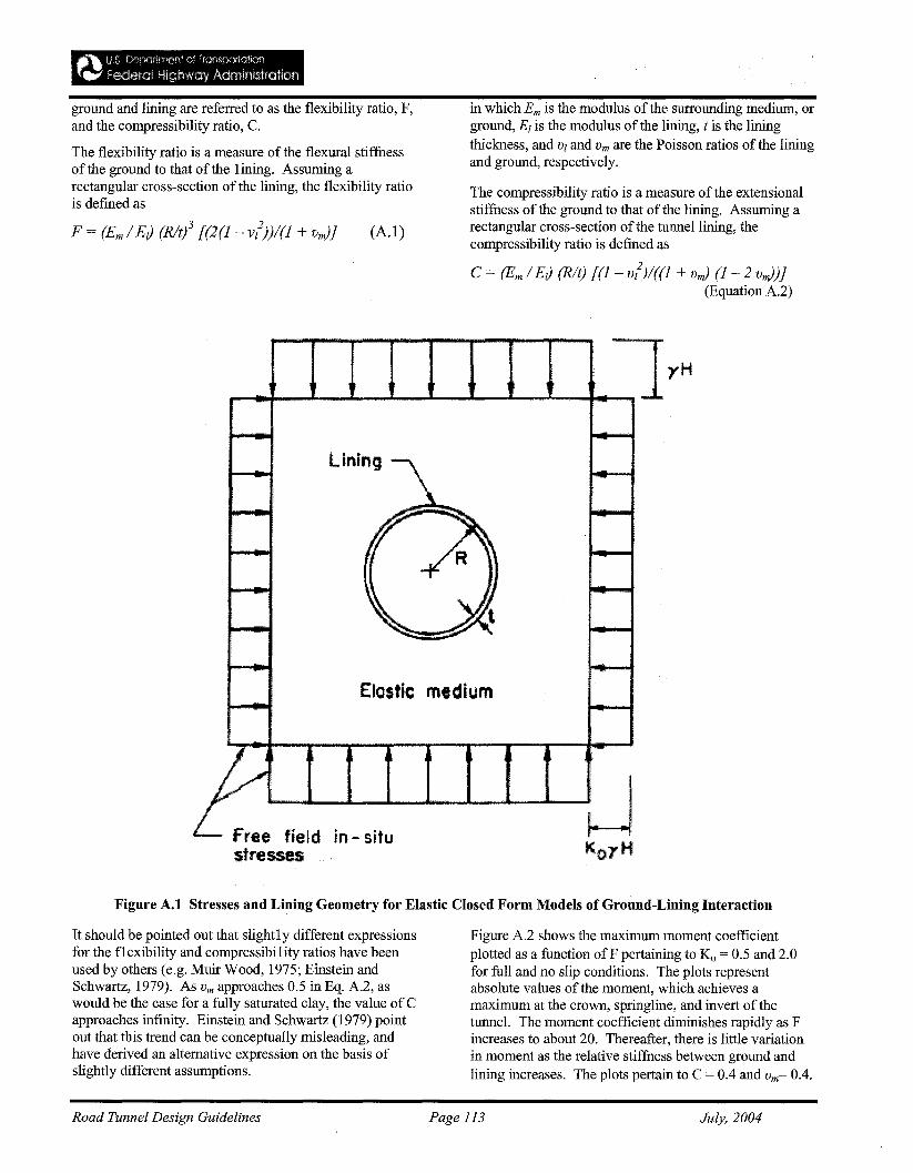
ground and lining are referred to as the flexibility ratio, F,and the compressibility ratio, C.
The flexibility ratio is a measure of the flexural stiffuessof the ground to that of the lining. Assuming arectangular cross-section of the lining, the flexibility ratiois defmed as
F = (Em / EJ (Rltl [(2(1- v/))/(1 + vJ) (A. I)
in which Ern is the modulus of the surrounding medium, orground, E[ is the modulus of the lining, t is the liningthickness, and v[ and Vm are the Poisson ratios ofthe liningand ground, respectively.
The compressibility ratio is a measure of the extensionalstiffuess of the ground to that of the lining. Assuming arectangular cross-section of the tunnel lining, thecompressibility ratio is defmed as
C = (Em / EJ (Rlt) [(1 - v/)/((1 + vJ (1 - 2 vJ)}(Equation A.2)
Elostic medium
Figure A.I Stresses and Lining Geometry for Elastic Closed Form Models of Ground-Lining Interaction
It should be pointed out that slightly different expressionsfor the f1 exibility and compressibi1ity ratios have beenused by others (e.g. Muir Wood, 1975; Einstein andSchwartz, 1979). As V rn approaches 0.5 in Eq. A.2, aswould be the case for a fully saturated clay, the value of Capproaches infinity. Einstein and Schwartz (1979) pointout that this trend can be conceptually misleading, andhave derived an alternative expression on the basis ofslightly different assumptions.
Figure A.2 shows the maximum moment coefficientplotted as a function ofF pertaining to Ko = 0.5 and 2.0for full and no slip conditions. The plots representabsolute values of the moment, which achieves amaximum at the crown, springline, and invert of thetunnel. The moment coefficient diminishes rapidly as Fincreases to about 20. Thereafter, there is little variationin moment as the relative stiffuess between ground andlining increases. The plots pertain to C = 0.4 and vm= 0.4.
Road Tunnel Design Guidelines Page 113 July, 2004
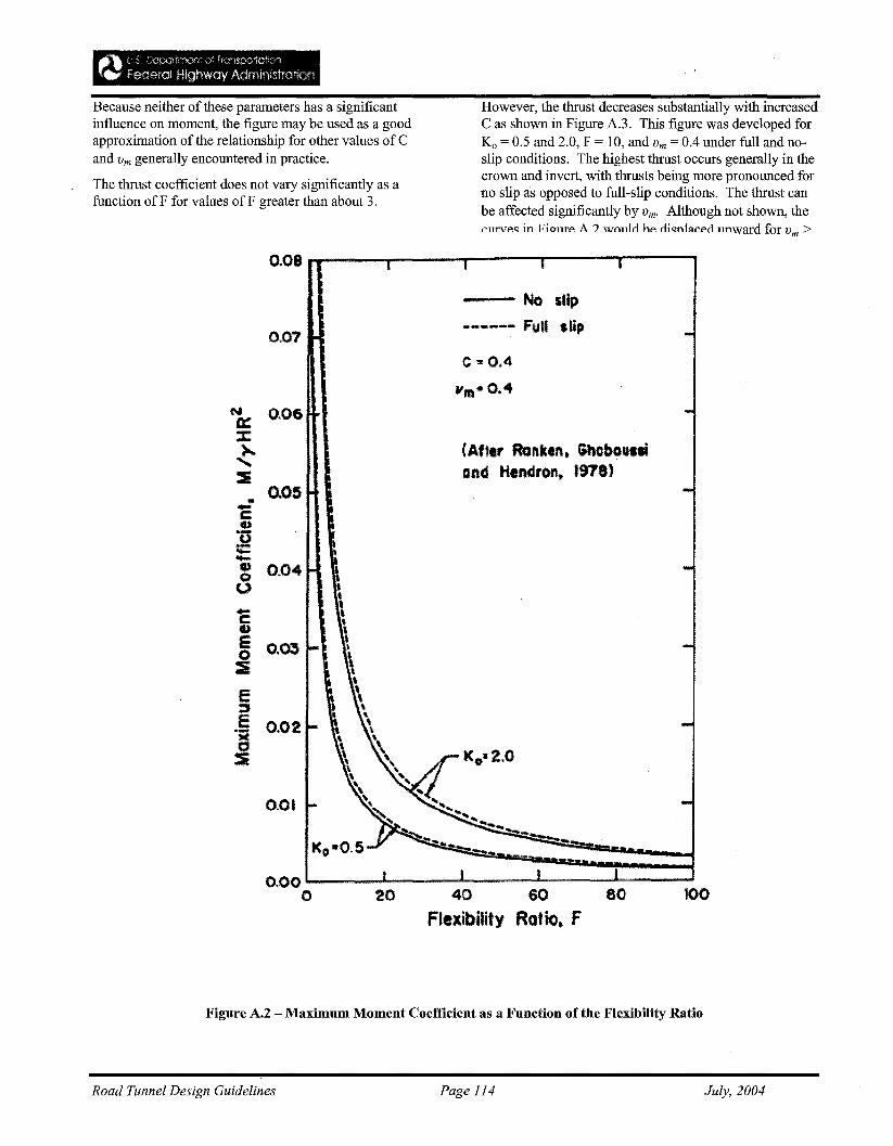
Because neither of these parameters has a significantinfluence on moment, the figure may be used as a goodapproximation of the relationship for other values of Cand Vm generally encountered in practice.
The thrust coefficient does not vary significantly as afunction ofF for values ofF greater than about 3.
However, the thrust decreases substantially with increasedC as shown in Figure A.3. This figure was developed forKo = 0.5 and 2.0, F = 10, and Vm = 0.4 under full and noslip conditions. The highest thrust occurs generally in thecrown and invert, with thrusts being more pronounced forno slip as opposed to full-slip conditions. The thrust canbe affected significantly by Vm' Although not shown, thePllrvf':<;: in FiO"llTf': A ? wfllllo hf': oi<;:nl11Pf':onnward for Vm >
0.08 __..........-..,..---..,..---..,----r----,
0.07
~O.06
:c)..
......:I
0.05..ccu*0..,..--• 004O'oc:•g O.C»:&
e::J
E 002*M •o:i
0.01
No slip
----..... FuU stip
c '" 0.4
(Aner Ronken. Ghcbol'siand Hendron. 1978)
0.00 '--__.....1-__--1. ..1..-__..........__-....
o 20 40 60 80 100
Flexibility RaUo. F
Figure A.2 - Maximum Moment Coefficient as a Function of the Flexibility Ratio
Road Tunnel Design Guidelines Page 114 July, 2004
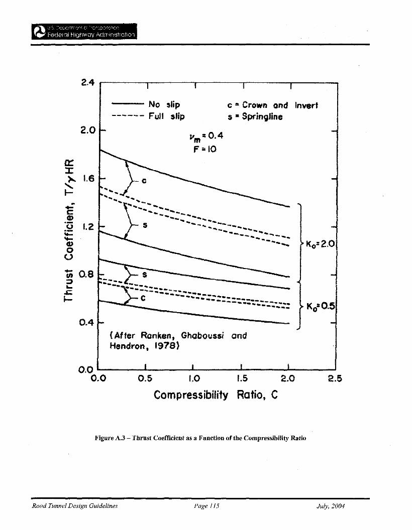
2.4 r----~---...__---,__---_r__--___.
No slip------ Full slip
C lit Crown and Inverts • Springline
Ko=O.5
vm=O.4F;IO
1.6
1.2
2.0
0.8
(After Ronken, Ghaboussi andHendron t 1978)
2.51.52.0
Ratio, C
().~ 1.0
Compressibility
0.0 -----..I---------~--------O~O
Figure A.3 - Thrust Coefficient as a Function of the Compressibility Ratio
Road Tunnel Design Guidelines Page 115 July, 2004
Figures A.2 and A.3 are instructive as indicators of thequalitative behavior of flexible tunnel linings. It should,however, be recognized that quantitative values foranalysis of specific cases depend considerably on thevalue assigned to the at-rest earth pressure coefficient, Ko,which must generally be estimated on the basis ofrelatively crude characterizations of actual site conditions.In sandy soils ofgeologically recent origin withrelatively high internal friction,Ko may approximate 0.5.In overconsolidated clays, Ko will often exceed 1.0. Inrocks that have been subject to complex geologicalprocesses, Ko may be extremely variable. Additionalcomp1ications arise because the excavation process tendsto relieve in-situ stresses adjacent to the tunnel lining.As a consequence, the lining may be subjected to a stressstate significantly less than that based on the assumptionof at-rest horizontal stresses and full overburden pressure.
A.3 Applications
The equations, on which Figures A.2 and A.3 are based,were developed for linear elastic linings. Concretelinings, however, are characterized by significantnonlinear stress-strain behavior. Structural failure of aconcrete lining results from crushing on the compressiveface, and the load bearing capacity of the lining maysignificantly exceed the structural bending capacity of thesection.
Linear elastic models may be biased to a reI atively lowassessment of the lining capacity because they tend toemphasize the bending capacity of the section.
The lining designer should recognize this bias. InAppendix B.2, the nonlinear responSe of a concrete liningis considered and compared with the response modeled bythe linear elastic solutions.
There are many factors in addition to the effects ofnonlinearity that the designer must consider. Concretecreep and the use of segmental linings may lead to anincrease in the relative stiffness between the ground andlining. The relief of in-situ stresses during excavationmay cause substantial reductions in pressure relative tothose inferred by excavation loading. The actual groundloads may not be distributed continously along the lining,but may be concentrated at specific locations as would bethe case for gravity loads in jointed rock and soil wheresignificant loosening is permitted. Moreover, loads fromshove jacks and contact grouting as well as thoseassociated with future construction may be more criticalthan the loads from ground-lining interaction.
Careful evaluation of the many factors affecting liningresponse requires judgment. Linear elastic modelssupp1ement judgment. As discussed previously, themodels are appropriate Iy used when they bracket thelimiting conditions ofperformance and point out trends inlining response as a result of variations of importantparameters.
Road Tunnel Design Guidelines Page 116 July, 2004

APPENDIX B.2 - LINEAR RESPONSE OF. CONCRETE LININGS
As discussed in Appendix B.1, concrete linings arecharacterized by nonlinear stress-strain behavior so thatlinear elastic models may lead to results that are notconsistent with actual performance. It is useful, therefore,to understand how linings are influenced by nonlinearcharacteristics. The moment-thrust diagram provides ameans of comparing linear and nonlinear responses undersimilar conditions of loading and relative stiffnessbetween the ground and concrete lining. This appendixprovides a brief discussion of moment-thrust diagramsand summarizes analytical results showing the differencesbetween 1ining performance modeled with linear andnonlinear concrete properties.
B.l Moment-Thrust Interaction Diagrams
When the thrust and moment around the lining have beencalculated, it is necessary to evaluate these quantities incomparison with allowable values. Normally, it is onlynecessary to make this comparison at locations where oneof the quantities is maximum or where there is an abruptchange in the lining section. Moment and thrust interactstrongly, so it is customary to check these quantitiestogether by using the moment thrust (M-T) interactiondiagram to represent the allowable combination. The MT interaction diagram can be drawn for each section of thelining and depends only on the section dimensions andmaterial properties.
One way to obtain a M-T interaction diagram is to use theprocedure of the ACI Code (ACI Committee 318, 1983)in which the combinations of moment and thrust, whichcause failure of the section under unconfined conditions,are computed and shown on a diagram in which thrust andmoment are the axes. A typical M-T diagram for onesection of a tunnel lining is shown in Figure B.1. Thisdiagram may represent all the lining sections if they haveconstant dimensions and composition, or several suchdiagrams may be used to represent different liningsections.
To determine whether the section for which the M-Tdiagram in Figure B.1 is adequate, the moment and thrustcombination obtained in the analysis should be plotted onthe diagram as shown. The ACI Code procedure forconstructing the diagram provides for capacity reductionfactors as a safety measure to cover uncertainties inmaterial properties, determination of section resistance,and the difference between concrete strength fromcylinder tests and the structure. If the moment and thrustcombination lies inside the diagram, the section isadequate. If it lies outside the diagram, the section is notadequate. The loads on the lining may be multiplied by aload factor to give the moment and thrust combination anadditional margin of safety.
B.2 Linear and Nonlinear Response
Figure B.l shows the difference that would be obtainedbetween linear and nonlinear analyses for a lining sectioncomposed of reinforced concrete. In the figure, themoment-thrust paths are plotted for two differentconditions of relative stiffness between the ground andlining. The nonlinear and linear paths, which intersectthe interaction diagram below the balance point, pertain toa flexibility ratio less than that for the paths that intersectabove the balance point. Each path is the locus ofmoment and thrust combinations corresponding to a giventype of loading. As discussed in Chapter 3 and AppendixA, the loading and attendant ground-lining interactionmay be modeled by means of excavation, ov~rpressure, orgravity loading.
When linear analyses are performed, the material stressstrain response must follow a 1inear relationship eventhough the actual stresses carried by the 1ining may bewell above the analytical values. Linear analyses areusually used to design above ground structures, with theunder standing that linear assumptions are conservative.The error resulting from using linear analysis for a tunnellining will be more pronounced than for an above groundstructure because the confmement and greaterindeterminacy of the underground structure provide moreopportunity for moment redistribution.
As the nonlinear moment-thrust path in Figure B.1intersects the interaction diagram below the balance point,the concrete cracks and the eccentricity decreasesresulting in a higher value of thrust (point 2) than wouldbe obtained in the linear analysis (point 1). The sectionhas additional capacity even after the moment-thrust pathhas reached the envelope, and the thrust continues toincrease even though the moment capacity drops off(point 3). Above the balance point, the thrust capacitycalculated by nonlinear analysis will be closer to thatcalculated by linear analysis, as evidenced by comparingthe percentage difference between points 4 and 5 with thatofpoints 1 and 3.
A key aspect of the lining response, which is shown bynonlinear analysis, is that the concrete tunnel lining doesnot fail by excessive moment. It fails by thrust which isaffected indirectly by moment.
Figure B.2 helps illustrate the general conditionssummarized in Figure B.l by means of a specificexample. The figure shows the moment thrust interactiondiagram for a 9-in. (230 mm)-thick concrete liningsection. A one-foot length (305 mm)of a continuouslining with no reinforcing steel is considered. Also shownon the graph are moment thrust paths for the crown
Road Tunnel Design Guidelines Page 117 July, 2004

obtained from analyses of an 18-ft (5.5 m)-diametercircular lining with the same cross-section as that used todra,,: the interaction diagram. A uniform gravity load wasapplied across the tunnel diameter as shown in the figure.Nonlinear geometric and material properties of the liningwere modeled, as described by Paul, et al. (1983). Theanalyses were performed using a beam-spring simulationin. which the ratio of the tangential to radial springstiffness was one fourth. Analyses were performed withspring stiffness corresponding to moduli of thesurrounding medium of 111,000 and 1,850,000 psi (770and 12,800 MN/m2), representing soft and medium hardrock. The increased capacity associated with increasedstiffness of the media illustrated by the nearly two-folddifference in maximum thrust for the two cases. Whenthe moment and thrust are below the balance point, thethrust capacity from nonlinear analysis exceeds that from
linear analysis by four times. When the moment-thrustpaths intersect the M-T diagram above the balance point,the difference in maximum thrust between the linear andnonlinear analyses is only about 10 percent.
It s~ouldbe emphasized that nonlinear analysis is subjectto VIrtually all constraints that apply for linear models.As discussed in Appendix A, there are many additionalfactors the designer must consider, covering variations inmaterial properties, ground loading, and constructionmethods. Nevertheless, nonlinear analysis providesinsight regarding the manner in which the concrete liningdeforms and shares load with the surrounding ground.The results ofnonlinear modeling may be especiallyuseful for moment and thrust combinations below thebalance point of the interaction diagram, where 1inearevaluations tend to underestimate the load carryingcapacity by a significant margin.
Moment - thrustdlaoram
• ... Balonce point
Linear path
linearpath
Nonlinearpaths ---.-
Moment
Figure B.1 -- General Moment-Thrust Diagram for a Reinforced Concrete Liningwith Linear and Nonlinear Moment-Thrust Paths.
Road Tunnel Design Guidelines Page 118 July, 2004
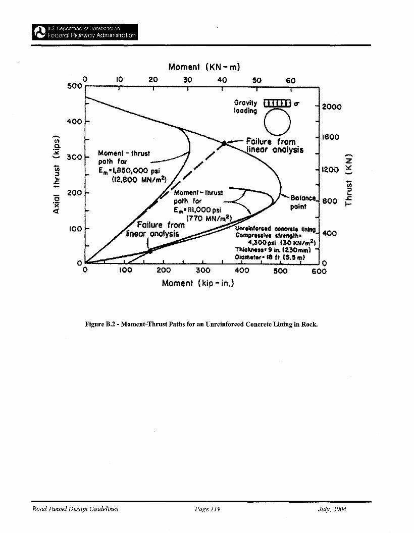
Moment (KN - m)20 30 40 5010o
500 ,...---.....---,..---,.---,...---.,....--.....--.......
1600
-z1200 ~-
400
-!.....800 ~
2000Gravity flIIl]J tr
loodin9 0-- Failure from
ineor analysis
400
100
_ 200o.;C<t
-(t).9-.=. 300
o~:c::~::i:--L----I...-J..---J~~~~~J 0o 100 200 300 400 500 600
Moment (kip - in.)
Figure B.2 - Moment-Thrust Paths for an Unreinforced Concrete Lining in Rock.
Road Tunnel Design Guidelines Page 119 July, 2004
APPENDIX C1 - TUNNEL BORING MACHINES',PERFORMANCE CONCEPTS AND PREDICTION
_ ' 2Fn-NePe 7r de /(4n) (C-I)
where Ne is the number of thrust cylinders;Pe'is the net
applied hydral.llic pressure; de is the diameter of each
cylinder piston; and n is the number of cutters in thearray.
Thrust delivered to the cutters is less than that calculatedbased on operating hydraulic pressure. If the backupsystem for a TBM is towed behind the TBM duringmining, then this loss of thrust should be subtracted, asshould friction losses from contact between the machineand the rock. For full shields, this loss can be very highand may ultimately stop forward progress, if groundpressures on the shield are larger than can be overcome byavailable thrust. The net average cutter nonnal force caneasily be 40 percent less than the calculated gross force.For very hard rock, thrust limits may severely restrictpenetration rate.
c. Disc rollingforce. Disc rolling is affected by suppliedmachine power .and cutterhead rotation. The average
rolling force per cutter, F r is calculated as:
where P , is the net delivered power; r is the cutterhead
rotation rate (rpm); and Re is the weighted average cutterdistance from the center of rotation. Losses on installedpower can also be significant, and overall torque system
efficiency is generally about 75 percent. Available F r canbe further reduced when motor problems temporarilydecrease available torque; sticky muck clogs thecutterhead and muck buckets resulting in torque lossesfrom friction and drag against rotation; or with a "frozen"or blocked cutter with a seized bearing. In fact, for manyTBMs operated in weak to moderately strong rock, torquecapacity limits penetration rate. This influence isdecreased in recent TBMs designed with variablecutterhead rotation rates and higher powered motors.Load capacity of a sidewall gripper system can also limitthe level of thrust and torque that can be applied. Withweak rock, the grippers may slide or develop localbearing capacity failure in the sidewall rock. In weakrock, wood cribbing may be required if overbreak is moreextensive than the gripper cylinder stroke. Theseproblems are particularly severe when mining from weakinto hard rock when high thrust is desired for efficientcutting, and the grippers must bear on low-strength rock.For shielded TBMs, the strength of the lining may limitoperating thrust and torque.
This appendix provides the following infonnation onTBM tunnels in rock for tunnel designers:
• TBM perfonnance specifications;
• Test data for perfonnance estimates, and;
• Cost estimating methods for TBM tunnels in rock.
The source document is the US Anny Corps ofEngine.erManual 1110-2-2901: Engineering & Design, Tunnelsand Shafts in Rock (1997); it is reproduced here, forconvenience.
C-l. TBM Design and Performance Concepts
The focus ofa site investigation and testing program isnot just to support the tunnel design. Testing results andrecommendations made must also sensitize the contractorto the site conditions before construction, a perspectivethat permits estimation of cost and schedule and supportsthe selection of appropriate excavation equipment. Thetests used to characterize muck for excavation purposesare often different from tests utilized in other civil worksand may depend on the excavation method. For'comparison of several alignments, a simple inexpensivetest may be sensitive enough to detect differences in"boreability", identify problem areas, and give an estimateof thrust and torque requirements.
a. Principles ofdisc cutting. TBM design andperfonnance predictions require an appreciation of basicprinciples of disc cutting. Figure C-1 illustrates the actionof disc cutting tools involving inelastic crushing of rockmaterial beneath the cutter disc and chip breakout byfracture propagation to an adjacent groove. The muckcreated in this process includes fme materials fromcrushing and chips from fracture. The fines are activeparticipants in disc wear. Rock chips have typicaldimensions of 15- to 25-mm thickness, widths on theorder of the cutter disc groove spacing, and lengths on theorder of two to four times the chip width. For efficientdisc cutting by a TBM, important items include:
• The cutter indenting, nonnal force, and penetrationmust be sufficient to produce adequate penetrationfor kerf interaction and chip fonnation.
• Adjacent grooves must be close enough for lateralcracks to interact and extend to create a chip.
• The disc force component must be adequate tomaintain cutter movement, despite rollingresistance! drag associated with penetration.
b. Normal forces. Disc penetration is affected by theapplied TBM thrust. The average thrust, or nonnal force(Fn), per cutter is calculated as:
Road Tunnel Design Guidelines Page 120
Fr =P'/(2 7r n r Re) (C-2)
July, 2004
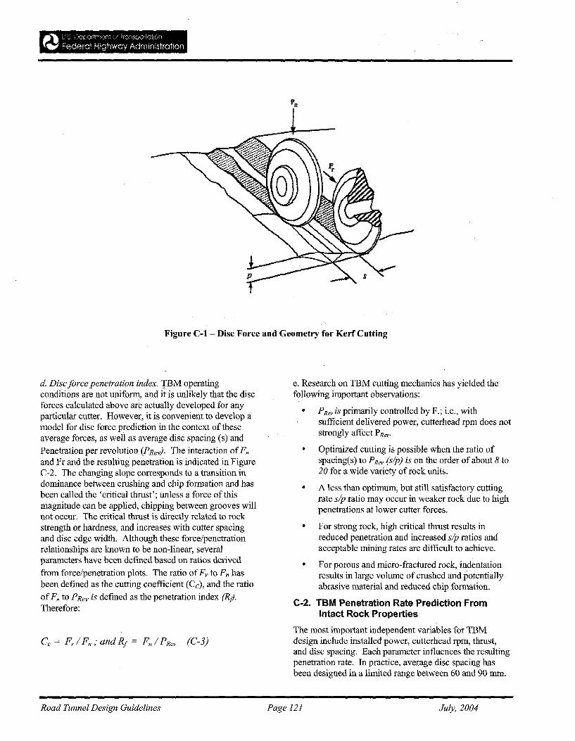
Figure C-l - Disc Force and Geometry for Kerf Cutting
d. Disc force penetration index. IBM operatingconditions are not uniform, and it is unlikely that the discforces calculated above are actually developed for anyparticular curter. However, it is convenient to devylop amodel for disc force prediction in the context of theseaverage forces, as well as average disc spacing (s) and
Penetration per revolution (PRev). The interaction ofFnand Fr and the resulting penetration is indicated in FigureC-2. The changing slope corresponds to a transition indominance between crushing and chip formation and hasbeen called the 'critical thrust'; unless a force ofthismagnitude can be applied, chipping between grooves willnot occur. The critical thrust is directly related to rockstrength or hardness, and increases with cutter spacingand disc edge width. Although these force/penetrationrelationships are known to be non-linear, severalparameters have been defined based on ratios derived
from force/penetration plots. The ratio ofFr to Fn hasbeen defined as the cutting coefficient (Cc), and the ratio
ofFn to PRev is defined as the penetration index (RlTherefore:
e. Research on TBM cutting mechanics has yielded thefoIlowing important observations:
• PRevis primarily controlled by F.; i.e., withsufficient delivered power, cutterhead rpm does notstrongly affect PRevo
• Optimized cutting is possible when the ratio ofspacing(s) to PRev (sip) is on the order of about 8 to20 for a wide variety ofrock units.
• A less than optimum, but still satisfactory cuttingrate sip ratio may occur in weaker rock due to highpenetrations at lower cutter forces.
• For strong rock, high critical thrust results inreduced penetration and increased sip ratios andacceptable mining rates are difficult to achieve.
• For porous and micro-fractured rock, indentationresults in large volume of crushed and potentiallyabrasive material and reduced chip formation.
C-2. TBM Penetration Rate Prediction FromIntact Rock Properties
The most important independent variables for TBMdesign include installed power, cutterhead rpm, thrust,and disc spacing. Each parameter influences the resultingpenetration rate. In practice, average disc spacing hasbeen designed in a limited range between 60 and 90 mm.
Road Tunnel Design Guidelines Page 121 July, 2004

Fixed design conditions include disc rolling velocity anddisc tool loading limits. Given accepted limits on discvelocity and loading and the general range of target sipratios used in practice, a method to predict relationshipsbetween Fn, Fr and PRev would permit a TBM designwith adequate power and thrust to achieve desiredpenetration rates.
a. Prediction methods. Many efforts have been made tocorrelate laboratory index test results to TBM penetrationrate. Prediction equations are either empirically derivedor developed with a theoretical basis using forceequilibrium or energy balance theories. Simplifiedassumptions of disc indentation geometry and contactzone stress distribution are made, and coefficients derived
from correlations with case history information are used.Most prediction methods agree on trends, but empiricalmethods are case-specific in terms of geology andmachine characteristics. However, a general statement ofcaution about the case history databases should be made.Prediction methods that do not consider operatingconditions of thrust and torque cannot be applied toprojects where equipment operations vary. The conditionof the cutters can also have a significant effect onperformance, since worn or blunted discs present widercontact areas on indentation and require higher forces fora given level ofpenetration. Some data bases includeperformance with single, double, and triple
Peneuurion
'"High Strength Rock
High Sb"ength Rock
F ...... ........c::;;;;..... .... FJlr
Figure C-2 - General Plot of Disc Cutter Force Variation with Penetration for High and Low-strength Rocks
disc cutters, a variation that greatly affects disc edgeloading and spacing penetration ratios. Finally, lowthrust and low-torque mining through poor ground oralignment curves may result in reduced penetration rates.
b. Penetration Index Tests. As examples of index testsused in correlations, several prediction approaches utilizestatic indentation tests performed on confined rockspecimens. A second group of index tests can be called"hardness" tests, including Shore Hardness, ScleroscopeHardness, Taber Abrasion Hardness, Schmidt HammerRebound Hardness (HR), and Total Hardness (HT), whichis calculated as the product ofHR and the square root ofthe Taber Abrasion Hardness. Dynamic impact tests havealso been developed for application to TBM performanceprediction. These include Rock Impact Hardness (RIH),
Coefficient of Rock Strength (CRS), and the SwedishBrittleness Test (S20) which is incorporated in theprediction method developed by the Norwegian Instituteof Technology NTH). Many "drillability" and"abrasivity" index tests have also been developed; eachrequires specialized equipment. The CERCHAR (theLaboratoire du Centre dEtudes at Recherches desCharbonnages de France) test has been used in assessing"abrasivity", and mineralogical abrasiveness measures,including quartz content and Mohr's hardness scale areused.
c. Rock strength testing.
(1) Empirically derived prediction equations have alsoincorporated results from "conventional" rock strengthtesting. The rock property most widely used in
Road Tunnel Design Guidelines Page 122 July, 2004
(4) Hughes (1986) derived a relationship from mining incoal:
(3) Graham (1976) derived a similar equation that usesUCS for a predominantly hard rock (UeS 140 to 200MPa) database:
where D is the disc diameter in millimeter, and it isassumed that only one disc tracks in each kerf groove, thenormal practice for TBM design.
e. Performance data.
(1) Rock properties and machine performance data forthree tunnel projects in sedimentary rock are used todemonstrate the predictive ability of these correlations inTable C-l. Rock test results, TBM performance, andpredicted penetration rates are shown in the table.Average disc forces vary directly with ues, and themaximum load is well below the maximum loadsuggested for the cutters used. In each case, TBMpenetration and thrust were limited by available torque orby the muck handling system capacity.
(2) The predicted penetrations are nearly always less thanachieved by TBMs in operation. The Farmer and Glossopequation yields consistently higher predicted penetrations,and the Graham predictions are consistently lowest. Theinfluence of rock test material condition is indicated bythe information for the Grimsby Sandstone.
Much of the original testing on this project was performedon air-dry rock. When the rock was re-saturated andtested, strength reduction was evident. This uncertaintyas to intact strength can clearly exert a strong influence onthe penetration rate predicted.
(3) The number of equations available leads to anapparent uncertainty in P Rev predictions. Suchcorrelations in the public domain have generally beenderived from limited databases, and caution againstindiscriminate application is required. In generalapplication, no single approach can be recommended;rather, use of several equations can be useful to assist indesign and selection of equipment and for sensitivitystudies of the relative importance of various factors.Thrust forces should, in any event, be increased by 15 to20 percent for TBM design capacity determination.
f Cutting Coefficients.
(1) Similar equations to predict Fr are not common,largely because while thrust is often monitored during
performance prediction has been the uniaxial compressivestrength (UeS) primarily because of the availability ofues test results. However, ues may not be the idealparameter for TBM performance prediction unless insituvariability ofUeS (or of index test results) is evaluated.
(2) Rock tensile strength, most often measured in a Braziltest, may also be used for machine performanceprediction. Test results can be used for weak rock toevaluate whether brittle behavior will occur on discindentation and to evaluate rock strength anisotropy.
(3) Rock fracture toughness and other fracture materialproperties (such as the critical energy release rate orcritical crack driving force) have great potentialapplication for machine performance prediction.However, few tests have been performed at tunnelingprojects so the correlations performance demonstrated todate must be considered preliminary.
(4) Other descriptive properties are also evaluated duringsite investigations, and many empirical correlations haveincluded these in linear regression equations. Suchproperties include density, porosity, water content, andseismic velocities. For weak rock, Atterberg limits andclay mineralogy should be evaluated early in the siteinvestigation, with more specialized testing for swell,squeeze, and consolidation properties perhaps warrantedon the basis of the results of index tests.
(5) At this time, a recommended suite of rock propertytests for tunnel project investigations should include bothtensile and compressive strength, an evaluation ofporosity or other measure of dilative versus compactiveresponse, and an evaluation ofrock "abrasivity". eareshould be taken with the core to minimize stress-reliefeffects and moisture loss. Sampling biases for or againstvery weak or very strong rock must be avoided, because itis these extremes that often define success or failure for aTBM application. F or use in specific predictiveapproaches, particular tests can be performed, such as thevarious hardness tests or the suite of tests incorporatedinto the NTH methodology. In all cases, specifiedequipment for index property testing is mandatory, andsuggested procedures must be followed. Guidanceconcerning required testing can be sought from TBMdesigners and consultants.
e. Empirical equations.
(1) Three commonly applied performance correlationsusing empirical equations developed from data on rocktesting are presented below, with PRev evaluated in unitsof millimetersIrevolution, Fn in kN, and the compressive(UCS) and Brazilian tensile (JIB) strengths expressed inunits of MPa or kPa, as noted.
(2) Farmer and Glossop (1980), who include mostlysedimentary rocks in their database, derived the followingequation:
PRev = 624 Fn / (JtB
PRev = 3940 Fn I UCS
PRev = 1.667 (Fn I UCS)1.2 * (2IDl· 6
(C-4)
(C-5)
(C-6)
Road Tunnel Design Guidelines Page 123 July, 2004
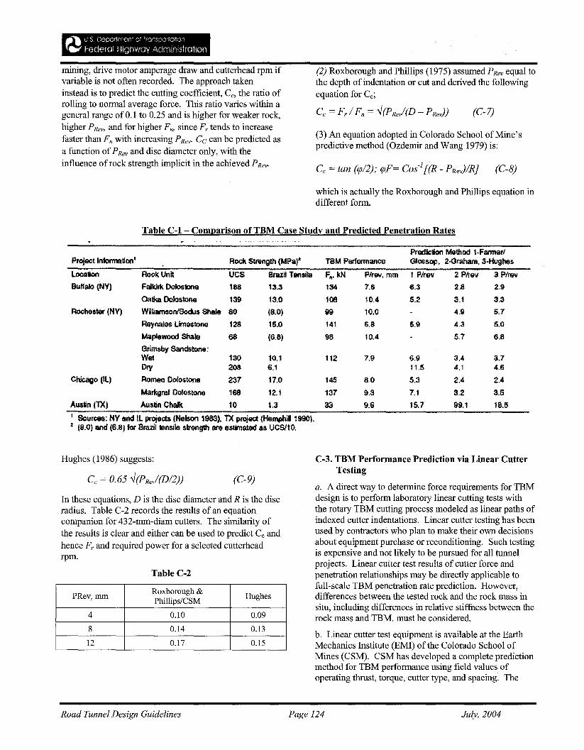
mining, drive motor amperage draw and cutterhead rpm ifvariable is not often recorded. The approach takeninstead is to predict the cutting coefficient, Cc, the ratio ofrolling to normal average force. This ratio varies within ageneral range of 0.1 to 0.25 and is higher for weaker rock,higher PRev, and for higher Fn, since Fr tends to increasefaster than Fn with increasing PRevo Cc can be predicted asa function ofPRev and disc diameter only, with theinfluence of rock strength implicit in the achieved PRevo
(2) Roxborough and Phillips (1975) assumed P Rev equal tothe depth of indentation or cut and derived the followingequation for Cc;
(3) An equation adopted in Colorado School of Mine'spredictive method (Ozdemir and Wang 1979) is:
Cc = tan (rp/2); rpF= Cos'][(R - PRev)lRj (C-8)
which is actually the Roxborough and Phillips equation indifferent form.
Table C-l - Comparison of TBM Case Study and Predicted Penetration Rates
Rock Strength (MPat TBM PerformancePrediction Method 1-FarmerJG1ossoP. 2·Granam. a·HugMs
3.74.6
2.4
3.5
18.6
3.44.1
2.4
3,2
99.1
1 Plrev 2 f/rev 3 P/ray
6.3 2.8 2.9
5.2 3.1 3.3
4.9: $.7
5.9 4,3 5.0
5.7 6.8
6,911.5
5.3
7.1
15.7
F•• kN P/rev, mm
134 7.6
108 10.4
99 ,0.0
141 6.8
98 10.4
112 7.9
145 8 ..0
137 9.3
33 9.6
UCS Brazil Tllnsile
188 13.3
139 13.0
SO (B.O)
128 15.0
68 (6.8)
LocationfkAffalo (NY)
Rochester (NY)
Chicago (Il)
RockUnilFalkilk Dolostone
Oab Dolostone
WBliamsontSodu$ Shale
Reynala$ limestone
Maplewood Shale
Gflmsby Sandstone;Wet 130 10.1DIy 208 6.1
Romeo Oofostone 237 17.0
Markgraf Doltlslone 168 12.1
Austin (TX) Auslirl Chalk 10 t3
I SoUl'09S: NY and II projects (Nelson 1983). TX pRlj9Ct (HemflhllI1990).• (8.0) and (6.8) for Brazil bmsite strength are estimated as UCSll0,
Hughes (1986) suggests:
(C-9)
In these equations, D is the disc diameter and R is the discradius. Table C-2 records the results of an equationcompanion for 432-mm-diam cutters. The similarity ofthe results is clear and either can be used to predict Cc andhence Fr and required power for a selected cutterheadrpm.
Table C-2
PRev,mmRoxborough &
HughesPhillips/CSM
4 0.10 0.09
8 0.14 0.13
12 0.17 0.15
C-3. TBM Performance Prediction via Linear CutterTesting
a. A direct way to determine force requirements for TBMdesign is to perform laboratory linear cutting tests withthe rotary TBM cutting process modeled as linear paths ofindexed cutter indentations. Linear cutter testing has beenused by contractors who plan to make their own decisionsabout equipment purchase or reconditioning. Such testingis expensive and not likely to be pursued for all tunnelprojects. Linear cutter test results of cutter force andpenetration relationships may be directly applicable tofull-scale TBM penetration rate prediction. However,differences between the tested rock and the rock mass insitu, including differences in relative stiffness between therock mass and TBM. must be considered.
b. Linear cutter test equipment is available at the EarthMechanics Institute (EMI) of the Colorado School ofMines (CSM). CSM has developed a complete predictionmethod for TBM performance using field values ofoperating thrust, torque, cutter type, and spacing. The
Road Tunnel Design Guidelines Page 124 July, 2004
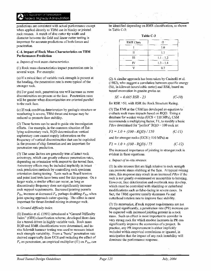
Table C-3
be identified depending on RMR classification, as shownin Table C-3:
(2) A similar approach has been taken by Casinelli et al.(1982), who suggest a correlation between specific energy(SE, in kilowatt hours/cubic meter) and RSR, based ontunnel excavation in granite gneiss as:
RMRClass f1 I
I 1.0
II 1.1
III 1.1 - 1.2
IV 1.3-1.4
V 0.7
(C-12)
(C-10)
(C-11)
SF = 0.665 RSR - 23
The increased importance ofjointing in stronger rock isevident in these equations.
c. Impact ofin-situ stresses.
(1) In situ stresses that are high relative to rock strengthcan promote stress slabbing at the face. At typical miningrates, this response may result in an increased PRev if therock is not greatly overstressed or susceptible to bursting.However, face deterioration and overbreak may develop,which must be controlled with shielding or cutterheadmodifications such as false-facing in severe cases. Infact, the TBM operator usually decreases Fn andcutterhead rotation rate to improve face stability.
(2) To summarize, ifrock support requirements are notchanged significantly, a penetration rate (PR) increase canbe expected with increased jointing present in a rockmass. Such an effect is most important to consider invery strong rock for which modest increases in PR cansignificantly improve the economics ofa project. Inpractice, any PR improvement is either implicitlyincluded within empirical correlations or ignored, inanticipation that the impact of any rock instability willdominate the performance response.
for RSR >50, with RSR the Rock Structure Rating.
(3) The EMI at the CSM has developed an equation toevaluate rock mass impacts based on RQD. Using adatabase for weaker rocks (UCS < 110 MPa), CSMrecommends a multiplying factor, Fl, to modify a basicPRev determined for "perfect" RQD = 100 rock as:
F1 = 1.0 + (100 - RQD) /150
and for stronger rocks (UCS 2: 110 MPa) as
F1 = 1.0 + (100 - RQD) / 75
predictions are consistent with actual performance exceptwhen applied directly to TBM use in blocky or jointedrock masses. A match of disc cutter tip width anddiameter between the field and linear cutter testing isimportant for accurate predictions of both forces andpenetration.
C-4. impact of Rock Mass Characteristics on TBMPerformance Prediction
a. Impact ofrock mass characteristics.
(1) Rock mass characteristics impact penetration rate inseveral ways. For example:
(a) If a mixed face ofvariable rock strength is present atthe heading, the penetration rate. is more typical of thestronger rock.
(b) For good rock, penetration rate will increase as morediscontinuities are present at the face. Penetration rateswill be greater when discontinuities are oriented parallelto the rock face.
(c) If rock condition deterioration by geologic structure orweathering is severe, TBM thrust and torque may bereduced to promote face stability.
(2) These factors can be used to guide site investigationefforts. For example, in the common situation of flatlying sedimentary rock, RQD determined on verticalexploratory core cannot supply information on thefrequency ofvertical discontinuities that can be exploitedin the process of chip formation and are important forpenetration rate prediction.
(3) The same factors are generally true of intact rockanisotropy, which can greatly enhance penetration rates,depending on orientation with respect to the tunnel face.Anisotropy effects may be included implicitly in intactrock prediction methods by controlling rock specimenorientation during testing. Tests such as Brazil tensionand point load tests have been used for this purpose. On alarger scale, a similar effect can occur, as long asdiscontinuity frequency does not significantly increaserock support requirements. Increased jointing permitsPRev increase at decreased F rz, perhaps doubling PRev whenjoint spacing approach cutter spacing. The effect is mostimportant for thrust-limited mining in stronger rock.
b. Ground difficulty index.
(1) Eusebio et al. (1991) introduced a "Ground DifficultyIndex" (GDI) classification scheme, developed from datafor a tunnel driven in highly variable rock. Rock massRQD and RMR classifications were determined, and insitu Schmidt hammer testing was used to measure intactrock strength variability. From a "basic" penetration ratederived empirically from UCS and including the effect ofFn on penetration, an empirical multiplier (fl) on PRev can
Road Tunnel Design Guidelines Page 125 July, 2004
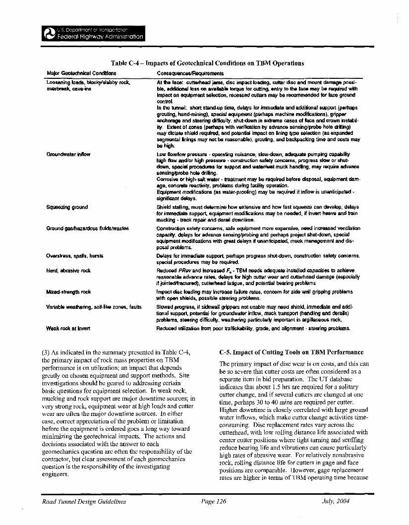
Table C-4 - Impacts of Geotechnical Conditions on TBM Operations
Major Geotechnical Conditions ConsequenoesJRsquirements
Loosening loads. blockylslabby rock, At the lace: cutledlead jams. disc impact loading, cutter disc and mount damage possi-0V8fb1$llk, cave-im; bre. addilional Ion on available torque for cutting, entry to the fa<:$ may~ required with
impact on equipment selection, recessed cutters may be recommended for face groundcontrol.In 1hG. tunnel: short s«and-Up time, delays for immediate and additional support (perhapsgrouting, hand-mining), specialequJpmenl (perhaps machine modifications), gripperanchorage and s!Hring difficulty. shut-down in extreme cases of face and Crown instability. Eldent 01 ZM8$ {perhaps With verification byadvanee sensing/probe hole ctillinglmay dictate shield required, and potential impact on fining type selection (as expandedsegmenlallinings may not be reasonable), grouting, and backpacking time and costs maybe high.
GrounONater inftow low f1owllow pressure - operating nuisance, slow-down, adequate pumping capabilityhigh flow andlor high pressure· construction safety concems, progress slow or shutdown, special procedures for support and waterlwet muck handling, may r&ql'ire advancesensing/probe hole driAiog.Corrosive or high-salt water - treatment may be required beforedispollal, equipment damage, concrete reaclivlty, problems during facility operation.Equipment modifications <as water·proo~ng) may be required it inflow is unanticipated significant delays.
Squeezing ground Shield stBlfing, mUlOt determine how extensive and how fast squeeze can dewlap, delaysfor immediate support, equipment modifications may be needed, if invert have and trainmucking. track repair and derail downtime.
Ground gaslhazardous ftuidslwastes Construction safety concerns, safe equipment more expensive, need increased ventilationcapacity. delays for advance sensing/probing and perhaps project shut·down, specialequipnKlnt modifications, with great delays, if unanticipated. muck management and disposal problems.
Overstress. spalls. bursts Delays for immediale s,upport, perhaps progress shut-down, construction safety concerns.special procedures may be required.
Hard, abrasive rock Reduced PRev and increased F" • TBM needs adequate installed capues to achievereasonable advance rates, delays for high cutter wear and cult9rhead damage (especiallyif jointedlfractured), cutterhead fatigue, and potential bearing problems
Mixed-strength rock Impact disc loading may increase failure rates, concern for sld9 wall gripping problemswilt. open shields, posslbie steering problems.
Variable weathering, soiI-Dke zones, faults Slowed progress, if sidewall grippers not usable may need shield, immediate and &ddi·tionalsuppott, potenlial for groundWater inflow, muck transport (handling and derails)plOblems, steering diffioulty, weathering particularly important in argillaceous rock,
Weak rock at invert ReckJced utilization !tom poor tmffiekabifity, grade, and alignment - steering problems.
(3) As indicated in the summary presented in Table C-4,the primary impact ofrock mass properties on TBMperformance is on utilization; an impact that dependsgreatly on chosen equipment and support methods. Siteinvestigations should be geared to addressing certainbasic questions for equipment selection. In weak rock,mucking and rock support are major downtime sources; invery strong rock, equipment wear at high loads and cutterwear are often the major downtime sources. In eithercase, correct appreciation of the problem or limitationbefore the equipment is ordered goes a long way towardminimizing the geotechnical impacts. The actions anddecisions associated with the answer to eachgeomechanics question are often the responsibility of thecontractor, but clear assessment of each geomechanicsquestion is the responsibility of the investigatingengineers.
C-5. Impact of Cutting Tools on TBM Performance
The primary impact of disc wear is on costs, and this canbe so severe that cutter costs are often considered as aseparate item in bid preparation. The UT databaseindicates that about 1.5 hrs are required for a solitarycutter change, and if several cutters are changed at onetime, perhaps 30 to 40 mins are required per cutter.Higher downtime is closely correlated with large groundwater inflows, which make cutter change activities timeconsuming. Disc replacement rates vary across thecutterhead, with low rolling distance life associated withcenter cutter positions where tight turning and scuffingreduce bearing life and vibrations can cause particularlyhigh rates of abrasive wear. For relatively nonabrasiverock, rolling distance life for cutters in gage and facepositions are comparable. However, gage replacementrates are higher in terms of TBM operating time because
Road Tunnel Design Guidelines Page 126 July, 2004
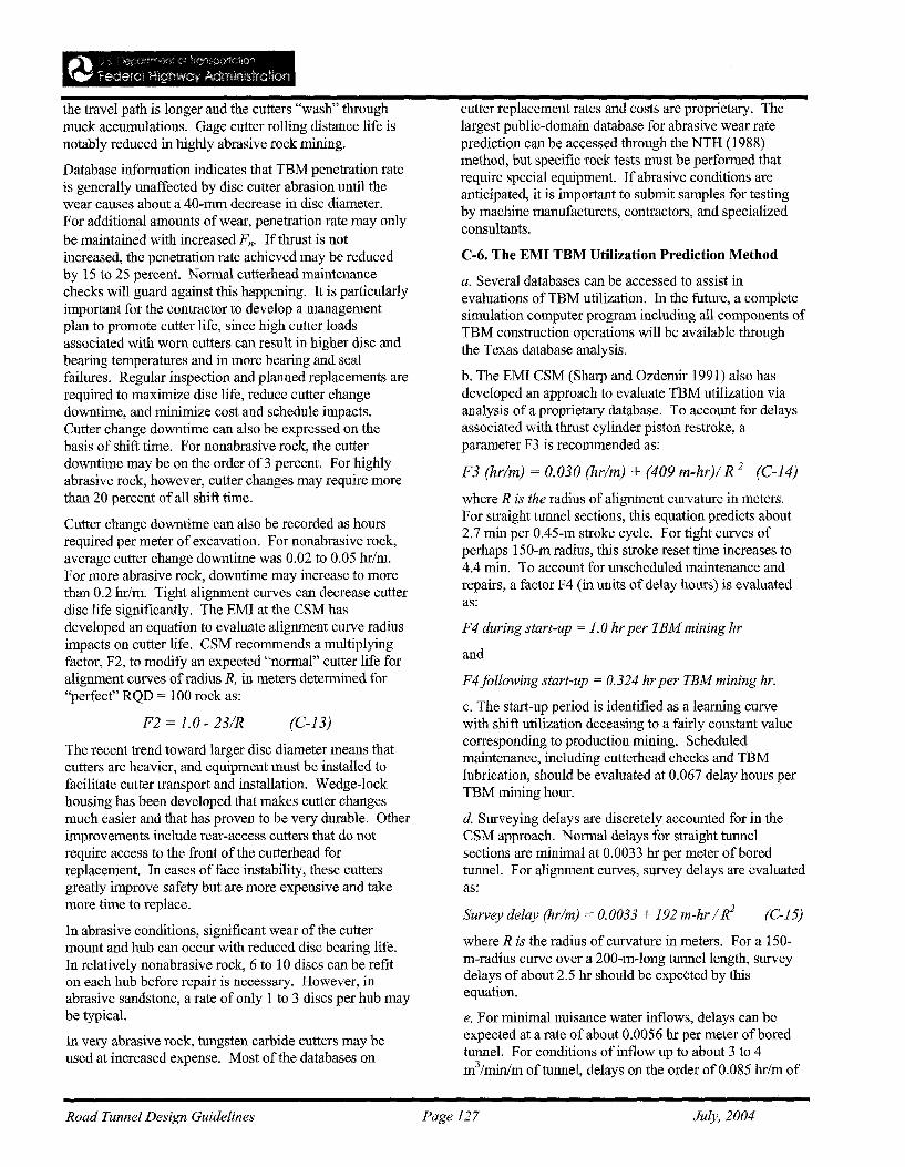
The recent trend toward larger disc diameter means thatcutters are heavier, and equipment must be installed tofacilitate cutter transport and installation. Wedge-lockhousing has been developed that makes cutter changesmuch easier and that has proven to be very durable. Otherimprovements include rear-access cutters that do notrequire access to the front of the cutterhead forreplacement. In cases of face instability, these cuttersgreatly improve safety but are more expensive and takemore time to replace.
In abrasive conditions, significant wear of the cuttermount and hub can occur with reduced disc bearing life.In relatively nonabrasive rock, 6 to 10 discs can be refiton each hub before repair is necessary. However, inabrasive sandstone, a rate of only 1 to 3 discs per hub maybe typical.
In very abrasive rock, tungsten carbide cutters may beused at increased expense. Most of the databases on
the travel path is longer and the cutters "wash" throughmuck accumulations. Gage cutter rolling distance life isnotably reduced in highly abrasive rock mining.
Database information indicates that TBM penetration rateis generally unaffected by disc cutter abrasion until thewear causes about a 40-mm decrease in disc diameter.For additional amounts ofwear, penetration rate may onlybe maintained with increased Fn. If thrust is notincreased, the penetration rate achieved may be reducedby 15 to 25 percent. Normal cutterhead maintenancechecks will guard against this happening. It is particularlyimportant for the contractor to develop a managementplan to promote cutter life, since high cutter loadsassociated with worn cutters can result in higher disc andbearing temperatures and in more bearing and sealfailures. Regular inspection and planned replacements arerequired to maximize disc life, reduce cutter changedowntime, and minimize cost and schedule impacts.Cutter change downtime can also be expressed on thebasis of shift time. For nonabrasive rock, the cutterdowntime may be on the order of 3 percent. For highlyabrasive rock, however, cutter changes may require morethan 20 percent of all shift time.
Cutter change downtime can also be recorded as hoursrequired per meter of excavation. For nonabrasive rock,average cutter change downtime was 0.02 to 0.05 hr/m.For more abrasive rock, downtime may increase to morethan 0.2 hr/m. Tight alignment curves can decrease cutterdisc life significantly. The EMI at the CSM hasdeveloped an equation to evaluate alignment curve radiusimpacts on cutter life. CSM recommends a multiplyingfactor, F2, to modify an expected "normal" cutter life foralignment curves of radius R, in meters determined for"perfect" RQD = 100 rock as:
C-6. The EMI TBM Utilization Prediction Method
where R is the radius of alignment curvature in meters.For straight tunnel sections, this equation predicts about2.7 min per OA5-m stroke cycle. For tight curves ofperhaps 150-m radius, this stroke reset time increases to4.4 min. To account for unscheduled maintenance andrepairs, a factor F4 (in units of delay hours) is evaluatedas:
(C-15)Survey delay (hr/m) = 0.0033 + 192 m-hr / R2
where R is the radius of curvature in meters. For a 150m-radius curve over a 200-m-long tunnel length, surveydelays of about 2.5 hr should be expected by thisequation.
e. For minimal nuisance water inflows, delays can beexpected at a rate ofabout 0.0056 hr per meter ofboredtunnel. For conditions of inflow up to about 3 to 4m3/min/m of tunnel, delays on the order of 0.085 hr/m of
F4 during start-up = 1.0 hr per TEM mining hr
and
F4 following start-up = 0.324 hr per TEM mining hr.
c. The start-up period is identified as a learning curvewith shift utilization deceasing to a fairly constant valuecorresponding to production mining. Scheduledmaintenance, including cutterhead checks and TBMlubrication, should be evaluated at 0.067 delay hours perTBM mining hour.
d. Surveying delays are discretely accounted for in theCSM approach. Normal delays for straight tunnelsections are minimal at 0.0033 hr per meter of boredtunnel. For alignment curves, survey delays are evaluatedas:
a. Several databases can be accessed to assist inevaluations of TBM utilization. In the future, a completesimulation computer program including all components ofTBM construction operations will be available throughthe Texas database analysis.
b. The EMI CSM (Sharp and Ozdemir 1991) also hasdeveloped an approach to evaluate TBM utilization viaanalysis of a proprietary database. To account for delaysassociated with thrust cylinder piston restroke, aparameter F3 is recommended as:
F3 (hr/m) = 0.030 (hr/m) + (409 m-hr)/ R 2 (C-14)
cutter replacement rates and costs are proprietary. Thelargest public-domain database for abrasive wear rateprediction can be accessed through the NTH (1988)method, but specific rock tests must be performed thatrequire special equipment. If abrasive conditions areanticipated, it is important to submit samples for testingby machine manufacturers, contractors, and specializedconsultants.
(C-13)F2 = 1.0 - 23/R
Road Tunnel Design Guidelines Page 127 July, 2004
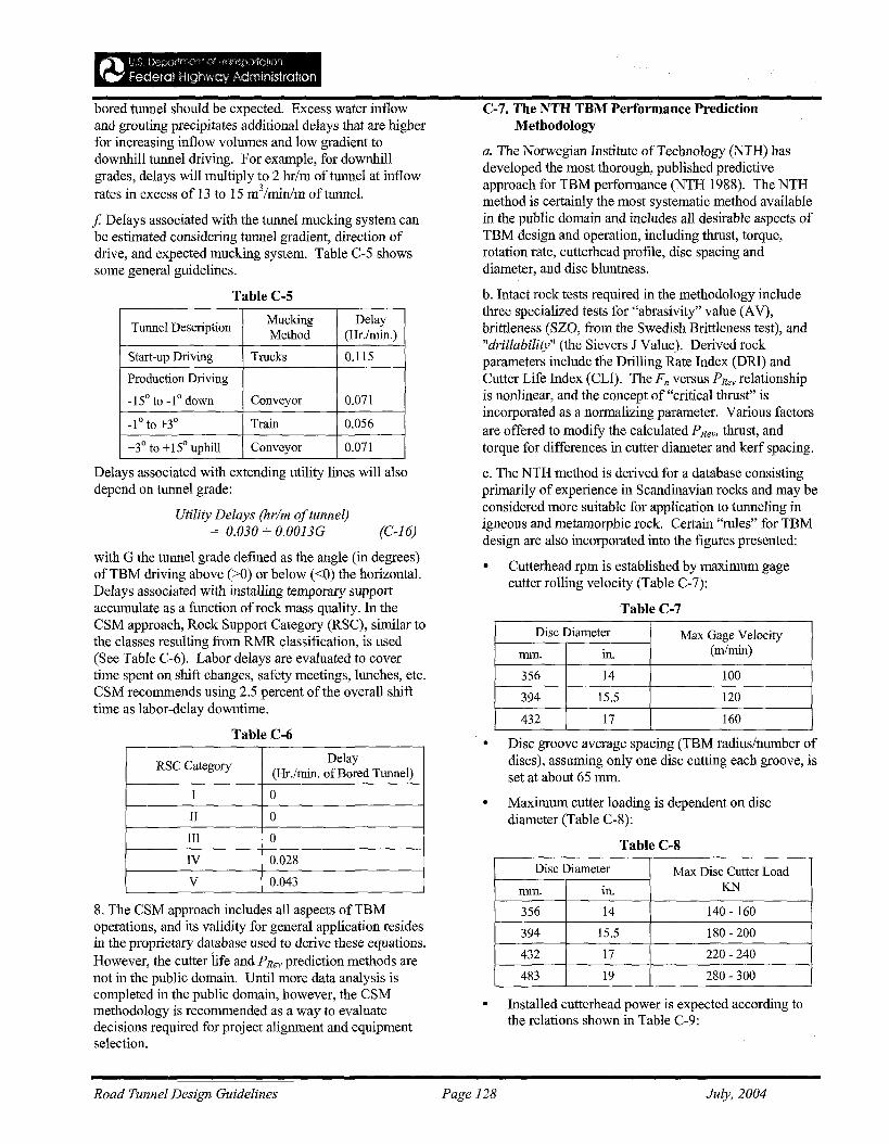
• Disc groove average spacing (TBM radius/number ofdiscs), assuming only one disc cutting each groove, isset at about 65 mm.
C-7. The NTH TBM Performance PredictionMethodology
a. The Norwegian Institute of Technology (NTH) hasdeveloped the most thorough, published predictiveapproach for TBM performance (NTH 1988). The NTHmethod is certainly the most systematic method availablein the public domain and includes all desirable aspects ofTBM design and operation, including thrust, torque,rotation rate, cutterhead profile, disc spacing anddiameter, and disc bluntness.
b. Intact rock tests required in the methodology includethree specialized tests for "abrasivity" value (AV),brittleness (8Z0, from the Swedish Brittleness test), and"drillability" (the Sievers J Value). Derived rockparameters include the Drilling Rate Index (DRl) andCutter Life Index (CLI). The Fn versus PRev relationshipis nonlinear, and the concept of "critical thrust" isincorporated as a normalizing parameter. Various factorsare offered to modify the calculated PRev, thrust, andtorque for differences in cutter diameter and kerf spacing.
c. The NTH method is derived for a database consistingprimarily of experience in Scandinavian rocks and may beconsidered more suitable for application to tunneling inigneous and metamorphic rock. Certain "rules" for TBMdesign are also incorporated into the figures presented:
• Cutterhead rpm is established by maximum gagecutter rolling velocity (Table C-7):
Table C-7
~~ t, I) t)='~,GrlfTV"2n~ <:'~ ~(G'ff\C<)10IJjYI
T.." federal High'iliay ,!\dmlfi'straM'f)
bored tunnel should be expected. Excess water inflowand grouting precipitates additional delays that are higherfor increasing inflow volumes and low gradient todownhill tunnel driving. For example, for downhillgrades, delays will multiply to 2 hr/m oftunnel at inflowrates in excess of 13 to 15 m3/minlm of tunnel.
f Delays associated with the tunnel mucking system canbe estimated considering tunnel gradient, direction ofdrive, and expected mucking system. Table C-5 showssome general guidelines.
Table C-5
Tunnel DescriptionMucking DelayMethod (Hr.lmin.)
Start-up Driving Trucks 0.115
Production Driving
_15° to -1° down Conveyor 0.071
-1°to+3° Train 0.056
+3° to +15° uphill Conveyor 0.071
Delays associated with extending utility lines will alsodepend on tunnel grade:
Utility Delays (hr/m oftunnel)= 0.030 + O.0013G (C-16)
with G the tunnel grade defined as the angle (in degrees)of TBM driving above (>0) or below «0) the horizontal.Delays associated with installing temporary supportaccumulate as a function ofrock mass quality. In theCSM approach, Rock Support Category (RSC), similar tothe classes resulting from RMR classification, is used(See Table C-6). Labor delays are evaluated to covertime spent on shift changes, safety meetings, lunches, etc.CSM recommends using 2.5 percent of the overall shifttime as labor-delay downtime.
Table C-6
RSC CategoryDelay
(Hr.lmin. of Bored Tunnel)
I 0
II 0
III 0
N 0.028
V 0.043
8. The CSM approach includes all aspects ofTBMoperations, and its validity for general application residesin the proprietary database used to derive these equations.However, the cutter iife and PRev prediction methods arenot in the public domain. Until more data analysis iscompleted in the public domain, however, the CSMmethodology is recommended as a way to evaluatedecisions required for project alignment and equipmentselection.
•
Disc Diameter Max Gage Velocity
mm. in. (mlmin)
356 14 100
394 15.5 120
432 17 160
Maximum cutter loading is dependent on discdiameter (Table C-8):
Table C-8
Disc Diameter Max Disc Cutter Load
mm. in. KN
356 14 140 - 160
394 15.5 180 - 200
432 17 220 - 240
483 19 280 - 300
Installed cutterhead power is expected according tothe relations shown in Dible C-9:
Road Tunnel Design Guidelines Page 128 July, 2004
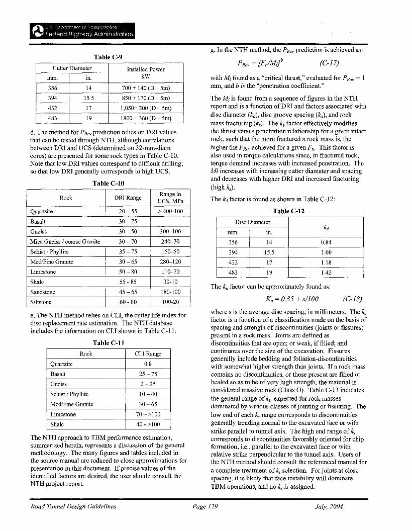
g. In the NTH method, the PRev prediction is achieved as:
with Mz found as a "critical thrust," evaluated for P Rev = Imrn, and b is the "penetration coefficient."
Disc Diameter
in.kd
tnrn.
356 14 0.84
394 15.5 1.00
432 17 1.18
483 19 1.42
(C-18)
(C-17)
Ka = 0.35 + s/100
The ka factor can be approximately found as:
The M zis found from a sequence of figures in the NTHreport and is a function of DR! and factors associated withdisc diameter (kd), disc groove spacing (ka), and rockmass fracturing (ks). The ks factor effectively modifiesthe thrust versus penetration relationship for a given intactrock, such that the more fractured a rock mass is, thehigher the PRev achieved for a given Fn. This factor isalso used in torque calculations since, in fractured rock,torque demand increases with increased penetration. TheMl increases with increasing cutter diameter and spacingand decreases with higher DRI and increased fracturing(high ks).
The kd factor is found as shown in Table C-12:
Table C-12
Cutter Diameter Installed Powertnrn. in. kW
356 14 700 + 140 (D - 5m)
394 15.5 850 + 170 (D - 5m)
432 17 1,050+ 200 (D - 5m)
483 19 1800 + 360 (D - 5m)
Table C-9
d. The method for PRev prediction relies on DR! valuesthat can be tested through NTH, although correlationsbetween DR! and UCS (determined on 32-mrn-diamcores) are presented for some rock types in Table C-IO.Note that low DR! values correspond to difficult drilling,so that low DR! generally corresponds to high UCS.
Table C-IO
Rock DRIRange Range inUCS,MPa
Quartzite 20-55 > 400-100
Basalt 30 -75
Gneiss 30 - 50 300-100
Mica Gneiss / coarse Granite 30-70 240-70
Schist / Phyllite 35 -75 150-50
MedlFine Granite 30- 65 280-120
Limestone 50- 80 110-70
Shale 55 - 85 30-10
Sandstone 45-65 180-100
Siltstone 60 - 80 100-20
e. The NTH method relies on CLI, the cutter life index fordisc replacement rate estimation. The NTH databaseincludes the information on CLI shown in Table C-ll:
Table C-ll
Rock CLI Range
Quartzite 0.8
Basalt 25 -75
Gneiss 2-25
Schist / Phyllite 10-40
Med/Fine Granite 30-65
Limestone 70->100
Shale 40 - >100
The NTH approach to TBM performance estimation,summarized herein, represents a discussion of the generalmethodology. The many figures and tables included inthe source manual are reduced to close approximations forpresentation in this document. Ifprecise values of theidentified factors are desired, the user should consult theNTH project report.
where s is the average disc spacing, in millimeters. The ks
factor is a function ofa classification made on the basis ofspacing and strength of discontinuities Goints or fissures)present in a rock mass. Joints are defined asdiscontinuities that are open; or weak, if filled; andcontinuous over the size of the excavation. Fissuresgenerally include bedding and foliation-discontinuitieswith somewhat higher strength than joints. If a rock masscontains no discontinuities, or those present are filled orhealed so as to be of very high strength, the material isconsidered massive rock (Class 0). Table C-13 indicatesthe general range of ks, expected for rock massesdominated by various classes ofjointing or fissuring. Thelow end of each ks range corresponds to discontinuitiesgenerally trending normal to the excavated face or withstrike parallel to tunnel axis. The high end range of ks
corresponds to discontinuities favorably oriented for chipformation, i.e., parallel to the excavated face or withrelative strike perpendicular to the tunnel axis. Users ofthe NTH method should consult the referenced manual fora complete treatment of ks selection. For joints at closespacing, it is likely that face instability will dominateTBM operations, and no ks is assigned.
Road Tunnel Design Guidelines Page 129 July, 2004
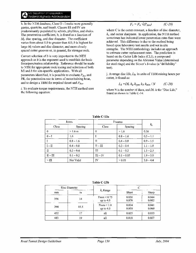
where N is the number of discs, and DL is the "Disc Life,"found as shown in Table C-14:
j. Average disc life, Lh, in units ofTBM mining hours percutter, is found as:
where C is the cutter constant, a function ofdisc diameter,ks, and cutter sharpness. In application, the NTH methodsometimes has indicated lower penetration rates than wereachieved. This difference is due to the method beingbased upon laboratory test results and not in situstrengths. The NTH methodology includes an approachto estimate cutter replacement rates. The prediction isbased on the Cutter Life Index (CLI), a compoundparameter depending on the Abrasion Value (determinedfor steel rings) and the Siever's J-value (a "drillability"test).
(C-19)
(C-20)
h. In the NTH database, Class 0 - I rocks were generallygneiss, quartzite, and basalt. Classes III and IV arepredominantly populated by schists, phyllites, and shales.The penetration coefficient, b, is found as a function ofMI, disc spacing, and disc diameter. The coefficientvaries from about 1.0 to greater than 4.0; b is highest forlarge MI values and disc diameter, and more closelyspaced cutter grooves or, in general, for stronger rock.
Correct selection of b is very important to the NTHapproach as it is the exponent used to establish the basicforce/penetration relationship. Reference should be madeto NTH for appropriate rock testing and selection of bothMl and b for site-specific applications. With allparameters identified, it is possible to evaluate P Rev andPR, the penetration rate in terms of meter/mining hour,and to design a TBM for required thrust and PRevo
i. To evaluate torque requirements, the NTH method usesthe following equation:
Table C-13a
Joints Fissures
Class Spacing Class Spacingks
0 > 1.6m 0 > 1.6 0.36
0-1 1.6 I 0.8 -1.6 0.5 -1.1
I 0.8 -1.6 II 0.4- 0.8 0.9 -1.5
I - II 0.4 -0.8 II - III 0.2 - 0.4 1.1 - 1.8
II 0.2 -0.4 III 0.1- 0.2 1.3 -2.3
II - III 0.1 - 0.2 III-IV 0.1-0.05 1.9 - 3.0
> III Not Valid IV >0.05 3.0 -4.4
Table C-13b
Disc Diameter C
inksRange
Blunt Sharpmm
356 14 From < 0.75 0.038 0.044up to 4.0 0.070 0.082
394 15.5 From < 1.0 0.034 0.041up to 4.0 0.050 0.060
432 17 all 0.025 0.033
483 19 all 0.018 0.027
Road Tunnel Design Guidelines Page 130 July, 2004
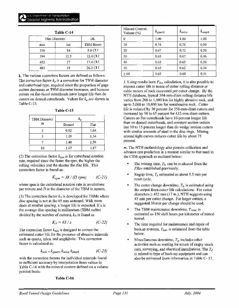
Mineral Content,kquartz k mica kamphTable C-14 Volume(%)
Disc Diameter DL 0 1.00 1.00 1.00
mm ins TBMHours 10 0.74 0.78 0.90
356 14 8.6 CLI 20 0.67 0.72 0.58
394 15.5 12.4 CLI 30 0.65 0.67 0.46
432 17 17.4 CLI 40 0.65 0.65 0.38
483 19 26.3 CLI 50 0.65 0.62 0.34
k. The various correction factors are defined as follows: 2': 60 0.65 0.60 0.31
Table C-15
The correction factor kmin is designed to correct theestimated cutter life for the presence of abrasive mineralssuch as quartz, mica, and amphibole. This correctionfactor is calculated as:
(2) The correction factor krpm is for cutterhead rotationrate, required since the faster the rpm, the higher therolling velocities and the shorter the disc life. Thiscorrection factor is found as:
1. Using results hom PRev calculation, it is also possible toexpress cutter life in terms ofcutter rolling distance orcubic meters of rock excavated per cutter change. By theNTH database, typical 394-mm-diam rolling distance lifevaries from 200 to 1,000 km for highly abrasive rock, andup to 5,000 to 10,000 km for nonabrasive rock. Cutterlife is reduced by 30 percent for 356-mm-diam cutters andincreased by 50 to 65 percent for 432-mm-diam cutters.Cutters on flat cutterheads have 10-percent longer lifethan on domed cutterheads, and constant section cutterslast 10 to 15 percent longer than do wedge section cutterswith similar amounts of steel in the disc rings. Miningaround tight curves reduces cutter life by about 75percent.
m. The NTH methodology also permits utilization andadvance rate prediction in a manner similar to that used inthe CSM approach as outlined below:
• The mining time, Tb, can be evaluated from thePRev established previously.
• Regrip time, T" estimated as about 5.5 min perreset cycle.
• The cutter change downtime, Tlv is estimated usingthe output from cutter life calculations. For cutterdiameters 2: 432 mm (17 in.), NTH suggests using45 min per cutter change. For larger cutters, asuggested 50 min per change should be used.
• The TBM maintenance downtime, TTBU isestimated as 150 shift hours per kilometer ofminedtunnel.
• The time required for maintenance and repair ofbackup systems, Tbalv is estimated from the tablebelow.
• Miscellaneous downtime, T(h includes otheractivities such as waiting for return of empty muckcars, surveying, and electrical installations. The Tdis related to type ofback-up equipment and canalso be estimated from information in Table C- 17.
(C-23)
(C-22)
(C-21)K rpm = 38/ (D rpm)
kmin = kquartz k mica kamph
TBM Diameter krpm Domed Flat
3 0.92 1.04
5 1.19 1.34
7 1.40 1.58
10 1.67 1.87
with the correction factors for individual minerals foundto sufficient accuracy by interpolation from values inTable C-16 with the mineral content defined on a volumepercent basis:
where rpm is the cutterhead rotation rate in revolutionsper minute and D is the diameter of the TBM in meters.
(3) The correction factor kN is developed for TBMs wheredisc spacing is not at the 65 mm assumed. With morediscs at smaller spacing, a longer life is expected. If s isthe average disc spacing in millimeters (TBM radiusdivided by the number of cutters), kN is found as
The correction factor krp is a correction for TBM diameterand cutterhead type, required since the proportion of gagecutters decreases as TBM diameter increases, and becausecutters on flat-faced cutterheads have longer life than docutters on domed cutterheads. Values for krp are shown inTable C-15.
Table C-16
Road Tunnel Design Guidelines Page 131 July, 2004
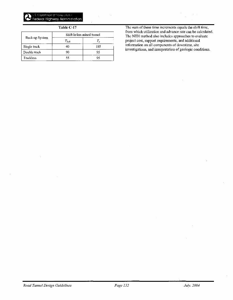
Table C-17
Shift hr/km mined tunnelBack-up System
Tbak Ta
Single track 40 185
Double track 90 95
Trackless 55 95
The sum of these time increments equals the shift time,from which utilization and advance rate can be calculated.The NTH method also includes approaches to evaluateproject cost, support requirements, and additionalinformation on all components of downtime, siteinvestigations, and interpretation ofgeologic conditions.
Road Tunnel Design Guidelines Page 132 July, 2004
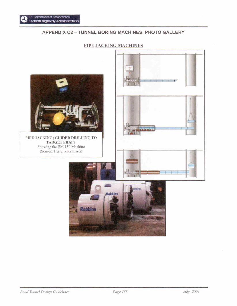
_", us Dcpor1m()o' <:J h<7lSDCtlOl"'"
"eo' Federal Highway AdministratIon
APPENDIX C2 - TUNNEL BORING MACHINES; PHOTO GALLERY
PIPE JACKING MACHINES
PIPE JACKING; GUIDED DRILLING TOTARGETSHAFT
Showing the 8M 150 Machine(Source: lIerrenknecht AG)
.• •
I
, ~\
IH'fl .---' .
Road TUIJnel Design GujdelilJe~ Page /33 Ju(I'. 100~

_" u5 IJeponmcol '" "<71"""""'00{..- federal Highway AdmlmslraNan
ROCKHEADS
SHIELDED TBMs
DOUBLE SHIELD TBi\1(9.51m dia.: Guadarrama Tunnel. Spain - Source: Hcrrenknecht AG)
Road TU1Jnel Design Guidelines Page 134 .l1I(1·. 2004
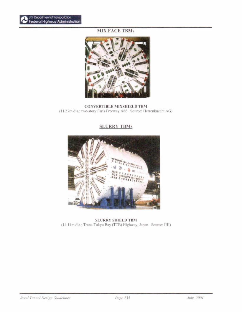
_", uS 1Jeoor1mor>- at "0"1"""""""f..- Federal Highway Admlmstrahoo
MIX FACE TBMs
CONVERTIBLE MIXSHIELD TBM(11.57111 dia.: two-stOry Paris Freeway A86. Source: Herrcnknecht AG)
SL RRY TBMs
SLURRY SHIELD TBM(14.14m dia.; Trans-Tokyo Bay (TTB) Highway. Japan. Source: 1111)
Road TUIlllel De.\;gl1 Guidelines Page J35 JII!\,. lOO",
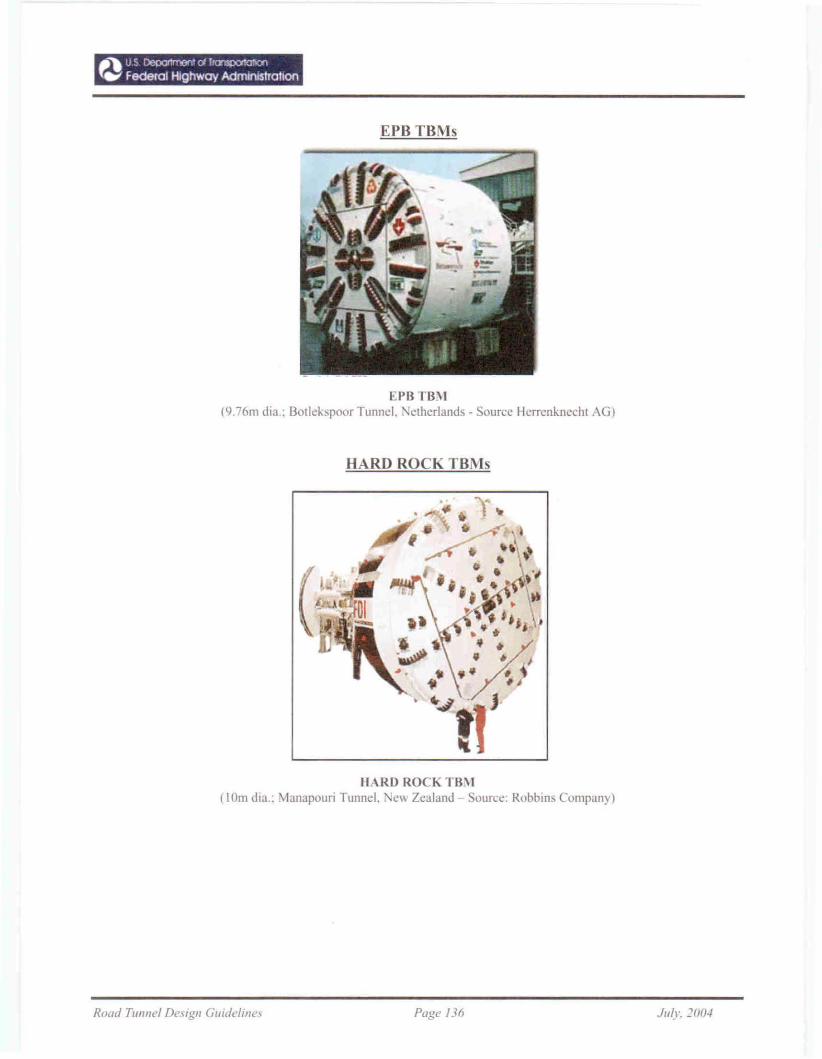
.~ uS Depor1mon'd I,<7lS)Ot!a1'C<l
tw Federal Highway Admlnlstrahan
ErB TBMs
EPB TBM(9.76m dia.; BOllehpoor Tunnel. 'etherlands - Source Hcrrenknechl AG)
HARD ROCK TBMs
HARD ROCK TBi\1(10m dla.: Manapouri Tunnel. e\\ Zealand Source: Robbins Company)
Road Tunnel Design Guideline., Page /36 Jllly. 2004
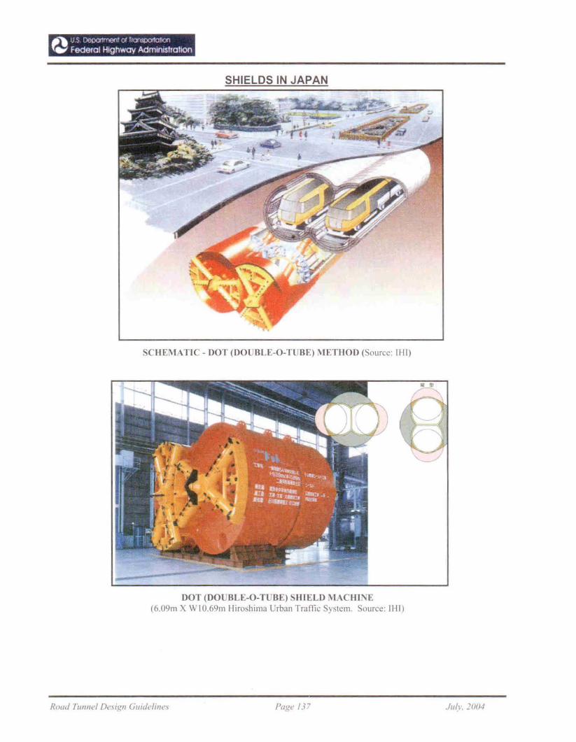
." U \ {)epa1M()O' 01 h<YIlPO'''''''''fW Federal Highway AdminIStration
SHIELDS IN JAPAN
SCHEMATIC - DOT (DOLJBLE-O-TLJBE) METHOD ( ouree: 1111)
DOT (DO BLE-O-TUBE) SHIELD j\IACBINE(6.09m X WIO.69m Hiroshima LJrban Traffic ysrem. ouree: IHI)
Road TUJlnel De_\igll Guidl'li"e~ Page 137 JIIIL ]1/1/4
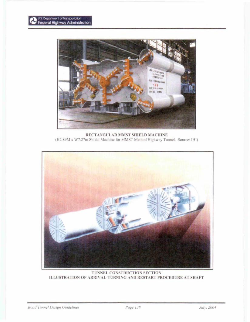
RECTANG LAR ~IMSTSHlELD MACHI'I'E(H2.89M x W7.27m Shield Machine for MMST Method Higl1\\ay Tunnel. Sonrce: IHI)
TUNNEL CONSTRUCTION SECTIONILL STRATION OF ARRIVAL-TURNING A:'>D RESTART PROCEDURE AT SHAFT
Road T/lnnel Design Guidelines Page /38 ./,,/.',. J(JIJ.!
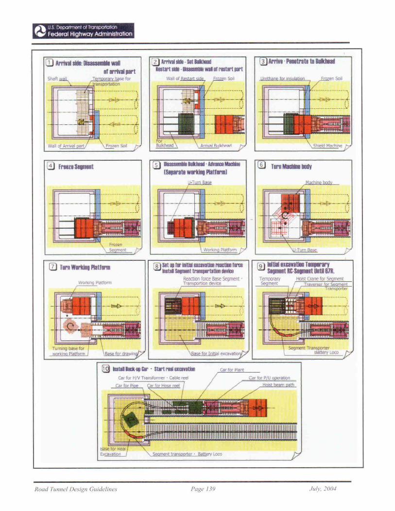
..... US DepOrtmen1 ()I ''':'''''0'101100{.,. Federal Highway AdministratIon
s",rt '
._ _-.~
\
-~H-·-~'---4·......., !:... ---.---.--- ' .- -_ - ~
._.~;.:;._._-*
~~~ _ !.'
:D lrrivaIlit8 . SIt IIIk!BIdI8ltart..•.......WIll fll'lIIla't IllI'l
~_"""""':'''''\-?i'i5~-t --..,*---~
.........-._-------.:..:
3 Arl'tVa.P8trals 1I1l11dni
4 frl8lt SIlllD8Dt 5 1l1l1Jl,*,1IIikIaI' AftIlll8 MIdfAIl
ISIJan1B warti1lt Platfll'llll6
'\. 5egment transpor1'¢f' Battery loc:o
. . ---,• • I
_·"""!-'.=;~--·--:f·
- _ ~)
® -.Jtlalualvatm T lI'YSIQmat .e- UntJ 61ft.
TanpoIOry HoI>' C",ne'''' s.o....'"SegmMt
Car for P U lIon
Car for Plane:
i---~--~
.....................~
.-~;;"'._------ .
_.,.-..t.- J... : ~
___ ...•..••.•..•.••. ':.1
8 set lit Til' IWIIllXtmtlll1 raclDr TII'IJ8nld SlIpI8l11rlllqlrtJ1Dr dB'fbI_"'ttl' Base~l'
T~alt$lX>rtion devICe
. .,\_....,"$_._._/
. ----------------_.:./
TlJmI!tg~ forlei nrm
ill TIl'I1 Workilll Platfll'1ll
Road TUI/llel Design Glddelines Page /39 ./1/(1'_ ]00';