Embed Size (px)
Citation preview
Carling Technologies, Inc.60 Johnson Avenue, Plainville, CT 06062Email: [email protected] Support: [email protected]: 860.793.9281 Fax: 860.793.9231
www.carlingtech.com
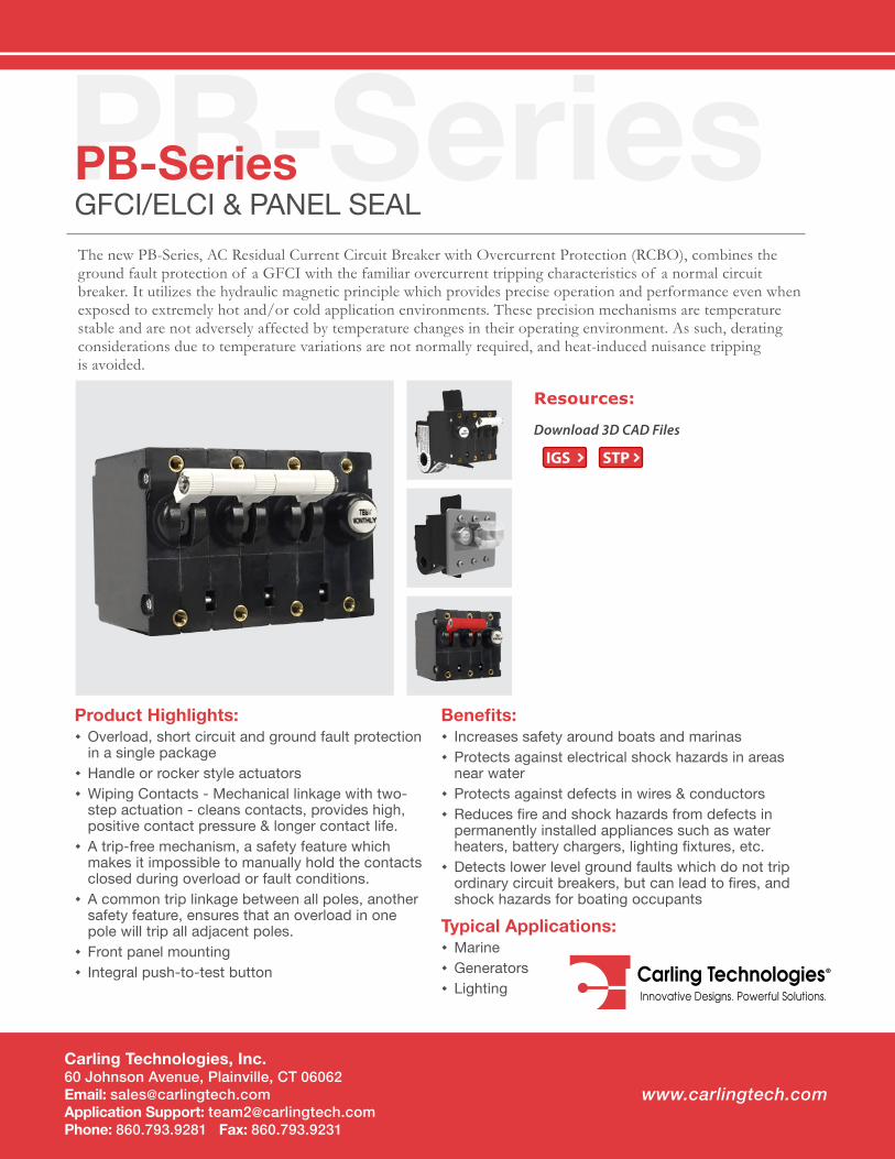
PB-SeriesPB-SeriesGFCI/ELCI & PANEL SEALThe new PB-Series, AC Residual Current Circuit Breaker with Overcurrent Protection (RCBO), combines the ground fault protection of a GFCI with the familiar overcurrent tripping characteristics of a normal circuit breaker. It utilizes the hydraulic magnetic principle which provides precise operation and performance even when exposed to extremely hot and/or cold application environments. These precision mechanisms are temperature stable and are not adversely affected by temperature changes in their operating environment. As such, derating considerations due to temperature variations are not normally required, and heat-induced nuisance tripping is avoided.
Product Highlights: � Overload, short circuit and ground fault protection in a single package
� Handle or rocker style actuators � Wiping Contacts - Mechanical linkage with two-step actuation - cleans contacts, provides high, positive contact pressure & longer contact life.
� A trip-free mechanism, a safety feature which makes it impossible to manually hold the contacts closed during overload or fault conditions.
� A common trip linkage between all poles, another safety feature, ensures that an overload in one pole will trip all adjacent poles.
� Front panel mounting � Integral push-to-test button
Benefits: � Increases safety around boats and marinas � Protects against electrical shock hazards in areas near water
� Protects against defects in wires & conductors � Reduces fire and shock hazards from defects in permanently installed appliances such as water heaters, battery chargers, lighting fixtures, etc.
� Detects lower level ground faults which do not trip ordinary circuit breakers, but can lead to fires, and shock hazards for boating occupants
Typical Applications: � Marine � Generators � Lighting
Download 3D CAD Files
Resources:
IGS STP
Email: [email protected] Application Support: [email protected] Phone: (860) 793–9281 Fax: (860) 793–9231 www.carlingtech.com
2 | PB-Series Circuit Breaker - General Specifications
*Manufacturer reserves the right to change product specification without prior notice.
0.100 - 5.05.1 - 20.0
20.1 - 30.0
CURRENT(AMPS)
0.1
0.1
0.01
0.0010.01
1000
100
10
1
± 15%± 25%± 35%
10 100
OHMS
RESISTANCE, IMPEDANCE VALUESfrom Line to Load Terminals
(Values Based on Series Trip Circuit Breaker)
TOLERANCE(%)
1
FIGURE 1
AMPERE RATING
Ampere Rating
t
Time in Milliseconds
16.67
60 Hz 1/2 CycleInrush Pulse Tolerance
Time Delay Curves22, 24, 26
4.165 8.33
rI
Mul
tiple
of
Rat
ed C
urre
nt
12x
Pulse Tolerance Curve
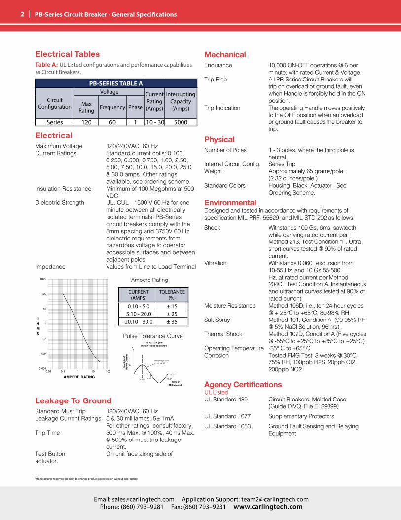
ElectricalMaximum Voltage 120/240VAC 60 HzCurrent Ratings Standard current coils: 0.100, 0.250, 0.500, 0.750, 1.00, 2.50, 5.00, 7.50, 10.0, 15.0, 20.0, 25.0 & 30.0 amps. Other ratings available, see ordering scheme. Insulation Resistance Minimum of 100 Megohms at 500 VDC. Dielectric Strength UL, CUL - 1500 V 60 Hz for one minute between all electrically isolated terminals. PB-Series circuit breakers comply with the 8mm spacing and 3750V 60 Hz dielectric requirements from hazardous voltage to operator accessible surfaces and between adjacent polesImpedance Values from Line to Load Terminal
Electrical TablesTable A: UL Listed configurations and performance capabilities as Circuit Breakers.
Leakage To GroundStandard Must Trip 120/240VAC 60 HzLeakage Current Ratings 5 & 30 milliamps. 5± 1mA For other ratings, consult factory. Trip Time 300 ms Max. @ 100%, 40ms Max. @ 500% of must trip leakage current. Test Button On unit face along side of actuator.
MechanicalEndurance 10,000 ON-OFF operations @ 6 per minute; with rated Current & Voltage.Trip Free All PB-Series Circuit Breakers will trip on overload or ground fault, even when Handle is forcibly held in the ON position.Trip Indication The operating Handle moves positively to the OFF position when an overload or ground fault causes the breaker to trip.
PhysicalNumber of Poles 1 - 3 poles, where the third pole is neutralInternal Circuit Config. Series TripWeight Approximately 65 grams/pole. (2.32 ounces/pole.)Standard Colors Housing- Black; Actuator - See Ordering Scheme.
EnvironmentalDesigned and tested in accordance with requirements of specification MIL-PRF- 55629 and MIL-STD-202 as follows:Shock Withstands 100 Gs, 6ms, sawtooth while carrying rated current per Method 213, Test Condition “I”. Ultra- short curves tested @ 90% of rated current.Vibration Withstands 0.060” excursion from 10-55 Hz, and 10 Gs 55-500 Hz, at rated current per Method 204C, Test Condition A. Instantaneous and ultrashort curves tested at 90% of rated current.Moisture Resistance Method 106D, i.e., ten 24-hour cycles @ + 25°C to +65°C, 80-98% RH.Salt Spray Method 101, Condition A (90-95% RH @ 5% NaCl Solution, 96 hrs).Thermal Shock Method 107D, Condition A (Five cycles @ -55°C to +25°C to +85°C to +25°C).Operating Temperature -35° C to +65° CCorrosion Tested FMG Test. 3 weeks @ 30°C 75% RH, 100ppb H2S, 20ppb CI2, 200ppb NO2
Agency CertificationsUL ListedUL Standard 489 Circuit Breakers, Molded Case, (Guide DIVQ, File E129899)UL Standard 1077 Supplementary ProtectorsUL Standard 1053 Ground Fault Sensing and Relaying Equipment
PB-SERIES TABLE A
Circuit Configuration
Voltage Current Rating (Amps)
Interrupting Capacity (Amps)
Max Rating Frequency Phase
Series 120 60 1 .10 - 30 5000
CURRENT (AMPS)
TOLERANCE (%)
0.10 - 5.0 ± 155.10 - 20.0 ± 25
20.10 - 30.0 ± 35
Email: [email protected] Application Support: [email protected] Phone: (860) 793–9281 Fax: (860) 793–9231 www.carlingtech.com
Email: [email protected] Application Support: [email protected] Phone: (860) 793–9281 Fax: (860) 793–9231 www.carlingtech.com
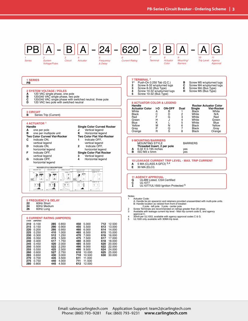
| 3 PB-Series Circuit Breaker - Ordering Scheme
1Series
2SystemVoltage/Poles
4Actuator
5Frequency& Delay
6Current Rating
7Terminal
8ActuatorColor
9Mounting/Barriers
10Trip Level
11AgencyApproval
3 Circuit
PB A B 2 AA B A G24 620
1 SERIESPB
2 SYSTEM VOLTAGE / POLESA 120 VAC single phase, one poleB 120/240 VAC single phase, two poleC 120/240 VAC single phase with switched neutral, three poleD 120 VAC two pole with switched neutral
7 TERMINAL 213 Push-On 0.250 Tab (Q.C.)2 Screw 8-32 w/upturned lugs3 Screw 8-32 (Bus Type)4 Screw 10-32 w/upturned lugs5 Screw 10-32 (Bus Type)
B Screw M5 w/upturned lugsC Screw M4 w/upturned lugsE Screw M4 (Bus Type)H Screw M5 (Bus Type)
9 MOUNTING/BARRIERS MOUNTING STYLE Threaded Insert, 2 per poleA 6-32 X 0.195 inchesB ISO M3 x 5mm
BARRIERS
yesyes
3 CIRCUIT B Series Trip (Current)
4 ACTUATOR 1HandleA one per poleB one per multipole unitTwo Color Curved Visi-RockerC Indicate ON, vertical legendD Indicate ON, horizontal legendF Indicate OFF, vertical legendG Indicate OFF, horizontal legend
Single Color Curved Rocker J Vertical legendK Horizontal legendTwo Color Flat Visi-Rocker1 Indicate OFF, vertical legend2 Indicate OFF, horizontal legendSingle Color Flat Rocker 3 Vertical legend4 Horizontal legend
5 FREQUENCY & DELAY22 60Hz Short24 60Hz Medium26 60Hz Long
6 CURRENT RATING (AMPERES)
210 0.100215 0.150220 0.200225 0.250230 0.300235 0.350240 0.400245 0.450250 0.500255 0.550260 0.600265 0.650270 0.700275 0.750280 0.800
285 0.850290 0.900295 0.950410 1.000512 1.250415 1.500517 1.750420 2.000522 2.250425 2.500527 2.750430 3.000435 3.500440 4.000445 4.500
450 5.000455 5.500460 6.000465 6.500470 7.000475 7.500480 8.000485 8.500490 9.000495 9.500610 10.000710 10.500611 11.000711 11.500612 12.000
712 12.500613 13.000614 14.000615 15.000616 16.000617 17.000618 18.000620 20.000622 22.000624 24.000625 25.000630 30.000
CODE AMPERES
10 LEAKAGE CURRENT TRIP LEVEL - MAX. TRIP CURRENT A 5 MA (CLASS A GFCI) 3,4E 30 MA (ELCI)
8 ACTUATOR COLOR & LEGENDHandle Rocker Actuator ColorActuator Color I-O ON-OFF Dual Single Visi-RockerWhite A B 1 Black WhiteBlack C D 2 White N/ARed F G 3 White RedGreen H J 4 White GreenBlue K L 5 White BlueYellow M N 6 Black YellowGray P Q 7 Black GrayOrange R S 8 Black Orange
Notes:1 Actuator Code: A: Handle tie pin spacer(s) and retainers provided unassembled with multi-pole units. B: Handle location as viewed from front of breaker: 2 pole - left pole 3 pole - center pole2 Screw Terminals are recommended on ratings greater than 20 amps. 3 Available with leakage current trip level - Max trip current code E, and agency approval C.4 30mA per UL1053, available with agency approval codes C & G.5 UL1500 only available with 30MA trip level.
11 AGENCY APPROVALG UL489 Listed, CSA CertifiedC UL1077I UL1077/UL1500 Ignition Protected 5
Email: [email protected] Application Support: [email protected] Phone: (860) 793–9281 Fax: (860) 793–9231 www.carlingtech.com
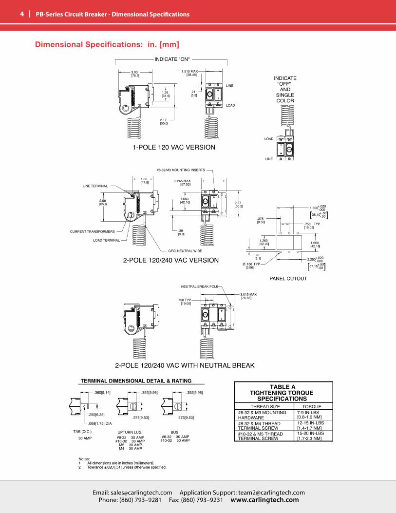
4 | PB-Series Circuit Breaker - Dimensional Specifications
3.0376.9[ ]
2.1755.0[ ]
1.515 MAX [38.48]
1.66042.16[ ]
.399.9[ ]
2.5865.6[ ]
1.8847.8[ ]
.215.3[ ]
1.2531.6[ ]
.750 TYP [19.05]
2.3760.2[ ]
1.66042.16[ ]
TYP.75019.05[ ]
1.500+.020-.000
38.10+.50-.00[ ]
2.250+.020-.000
57.15+.50-.00[ ]
1.26032.00[ ]
Ø TYP.1563.96[ ]
.3759.53[ ]
.205.1[ ]
2.265 MAX [57.53]
3.015 MAX [76.58]
GFCI NEUTRAL WIRE
2-POLE 120/240 VAC WITH NEUTRAL BREAK
INDICATE "ON"
INDICATE "OFF"AND
SINGLE COLOR
LINE
LOAD
LOAD
LINE
PANEL CUTOUT
1-POLE 120 VAC VERSION
2-POLE 120/240 VAC VERSION
LOAD TERMINAL
CURRENT TRANSFORMERS
LINE TERMINAL
#6-32/M3 MOUNTING INSERTS
NEUTRAL BREAK POLE
SCALE 0.500
SCALE 0.500
TEST
TEST
TEST
TEST
Notes: 1 All dimensions are in inches [millimeters].2 Tolerance ±.020 [.51] unless otherwise specified.
Dimensional Specifications: in. [mm]
Email: [email protected] Application Support: [email protected] Phone: (860) 793–9281 Fax: (860) 793–9231 www.carlingtech.com
Email: [email protected] Application Support: [email protected] Phone: (860) 793–9281 Fax: (860) 793–9231 www.carlingtech.com
| 5 PB-Series Circuit Breaker - Dimensional Specifications
Notes: 1 All dimensions are in inches [millimeters].2 Tolerance ±.020 [.51] unless otherwise specified.
Dimensional Specifications: in. [mm]
Email: [email protected] Application Support: [email protected] Phone: (860) 793–9281 Fax: (860) 793–9231 www.carlingtech.com
6 | PB-Series Circuit Breaker - Wiring Diagrams
120 VAC WITHOUT SWITCHED NEUTRAL120 VAC WITH SWITCHED NEUTRAL
GFCIMODULEPIGTAIL
LOADHOT
SYSTEM NEUTRAL
LOADNEUTRAL
AC SOURCE
120 VAC WITH SWITCHED NEUTRAL
120 VAC LOAD
LINE/SOURCE(HOT)
LINE/SYSTEMNEUTRAL
240 VAC LOAD
120 VAC LOAD
GFCIMODULEPIGTAIL
LOADHOT
1LOADHOT
2
LOADNEUTRAL
LINE/SOURCE
2
LINE/SOURCE 1 LINE/SYSTEMNEUTRAL
SYSTEMNEUTRAL
AC SOURCE
120/240 VAC WITH SWITCHED NEUTRAL
120 VAC LOAD
LINE/SOURCE(HOT)
LOADHOT
120 VAC LOAD
SYSTEM NEUTRAL
GFCIMODULEPIGTAIL
AC SOURCE
120 VAC WITHOUT SWITCHED NEUTRAL
LINE/SOURCE
(2)
LOADHOT(2)
LOADHOT1
SYSTEM NEUTRAL
120 VAC LOAD
GFCIMODULEPIGTAIL
AC SOURCE
120/240 VAC WITHOUT SWITCHED NEUTRAL
LINE/SOURCE(1)
120 VAC LOAD
240 VAC LOAD
120 VAC with Switched Neutral
120/240 VAC with Switched Neutral
120 VAC without Switched Neutral
120/240 VAC without Switched Neutral
120 VAC WITHOUT SWITCHED NEUTRAL120 VAC WITH SWITCHED NEUTRAL
Email: [email protected] Application Support: [email protected] Phone: (860) 793–9281 Fax: (860) 793–9231 www.carlingtech.com
Email: [email protected] Application Support: [email protected] Phone: (860) 793–9281 Fax: (860) 793–9231 www.carlingtech.com
| 7 PB-Series Circuit Breaker - Panel Seal Ordering Scheme
2Series
3Actuator
4Poles
5Mounting
1TypeNumber
PB 1 4 18
2 SERIESPB
1 TYPE NUMBER8 Circuit Breaker Assembly
5 MOUNTING SCREWS / PLATE MATERIAL 11 6-32 Thread Phillips Head2 M-3 Thread Phillips Head3 6-32 Thread Slotted Head4 M-3 Thread Slotted Head5 6-32 Thread Phillips Head with Stainless Steel Plate6 M-3 Thread Phillips Head with Stainless Steel Plate7 6-32 Thread Slotted Head with Stainless Steel Plate8 M-3 Thread Slotted Head with Stainless Steel Plate
3 ACTUATOR TYPE 1 Handle, one per pole2 Handle, one per multipole unitA Rocker 2
4 POLES PER UNIT - INCLUDING ELECTRONIC MODULE2 Two3 Three4 Four
Notes: 1 Screws supplied to accommodate mounting panel thickness of 1/8” ± 1/32”. Consult Factory for additional options2 Available for Flat and Curved Rocker options - No Rockerguard Bracket
Handle Style Panel Seal
Rocker Style Panel Seal
Email: [email protected] Application Support: [email protected] Phone: (860) 793–9281 Fax: (860) 793–9231 www.carlingtech.com
8 | PB-Series Circuit Breaker - Panel Seal Configuration - Dimensional Specifications
Handle Actuator
Rocker Actuator
Email: [email protected] Application Support: [email protected] Phone: (860) 793–9281 Fax: (860) 793–9231 www.carlingtech.com
Email: [email protected] Application Support: [email protected] Phone: (860) 793–9281 Fax: (860) 793–9231 www.carlingtech.com
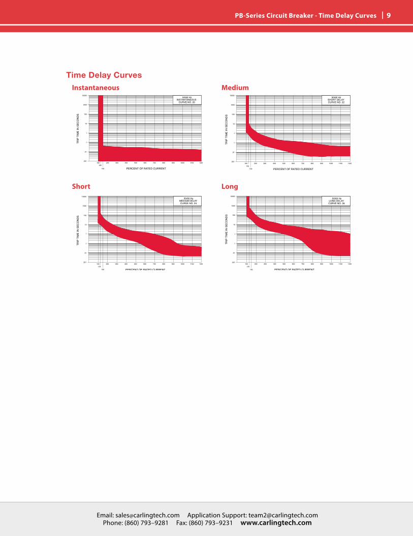
| 9 PB-Series Circuit Breaker - Time Delay Curves
Time Delay CurvesInstantaneous
Short
Medium
Long

Email: [email protected] Application Support: [email protected] Phone: (860) 793–9281 Fax: (860) 793–9231 www.carlingtech.com
10 | Notes
Email: [email protected] Application Support: [email protected] Phone: (860) 793–9281 Fax: (860) 793–9231 www.carlingtech.com
Email: [email protected] Application Support: [email protected] Phone: (860) 793–9281 Fax: (860) 793–9231 www.carlingtech.com
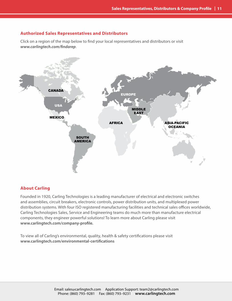
| 11 Sales Representatives, Distributors & Company Profile
Authorized Sales Representatives and Distributors
About Carling
Founded in 1920, Carling Technologies is a leading manufacturer of electrical and electronic switches and assemblies, circuit breakers, electronic controls, power distribution units, and multiplexed power distribution systems. With four ISO registered manufacturing facilities and technical sales offices worldwide, Carling Technologies Sales, Service and Engineering teams do much more than manufacture electrical components, they engineer powerful solutions! To learn more about Carling please visit www.carlingtech.com/company-profile.
To view all of Carling’s environmental, quality, health & safety certifications please visit www.carlingtech.com/environmental-certifications
Click on a region of the map below to find your local representatives and distributors or visit www.carlingtech.com/findarep.
EUROPE
MIDDLEEAST
SOUTHAMERICA
ASIA-PACIFICOCEANIA
AFRICAMEXICO
USA
CANADA

Worldwide HeadquartersCarling Technologies, Inc.60 Johnson Avenue, Plainville, CT 06062Phone: 860.793.9281 Fax: 860.793.9231Email: [email protected]
Northern Region Sales Office: [email protected] Region Sales Office: [email protected] Region Sales Office: [email protected] Region Sales Office: [email protected] America Sales Office: [email protected]
Asia-Pacific HeadquartersCarling Technologies, Asia-Pacific Ltd.,Suite 1607, 16/F Tower 2, The Gateway,Harbour City, 25 Canton Road,Tsimshatsui, Kowloon, Hong KongPhone: Int + 852-2737-2277 Fax: Int + 852-2736-9332Email: [email protected]
Shenzhen, China: [email protected], China: [email protected], India: [email protected], Taiwan: [email protected], Japan: [email protected]
Europe | Middle East | Africa HeadquartersCarling Technologies LTD4 Airport Business Park, Exeter Airport, Clyst Honiton, Exeter, Devon, EX5 2UL, UKPhone: Int + 44 1392.364422 Fax: Int + 44 1392.364477Email: [email protected]
Germany: [email protected]: [email protected]
www.carlingtech.com REV_11_2016

![5TT Mar2016DC1 - belfuse.com · Temperature Derating Curve 0 110 0 70 5 75 Ambient Temperature [ oc] Soldering Parameters Lead-free Wave Soldering Profile Wave Soldering Parameter](https://img.pdfslide.us/doc/110x75/5b5f24757f8b9af90c8d333e/5tt-mar2016dc1-temperature-derating-curve-0-110-0-70-5-75-ambient-temperature.jpg)