Embed Size (px)
Citation preview

146 Warner Electric 800-234-3369 ......P-1264-WE 3/14
Static Torque 5 lb.in.Maximum Speed 10,000 rpmStandard Voltage D.C. 6, 24, 90
ARMATURE VIEW
MAGNET VIEW
Customer Shall Maintain:1. Concentricity of brake mounting pilot diameter with
armature shaft within .003 T.I.R.2. Squareness of brake mounting face with
armature shaft within .003 T.I.R.
Bore Di men sions Armature Bore Dia.
.188/.187 .251/.250 (.313/.312)**(Antibacklash Armatures)
Antibacklash Arm.
Std. Arm.
For Bore sizes see chart below.
45°
1.499/1.497 Pilot Dia.
.130/.123 dia. (4) holes equally spaced
on 1.312 dia. Mounting holes are within .006 of true position relative to
pilot diameter.
1.125 Max. Sq.
.109 (Std.).140 (Anti.)
.015 When New
.072 (Std.).072 (Anti.) 12
.375 Dia.
#4-40 UNC-3A
.187 Max.
.062
.500
Anti Arm.
.015 Nom.
.072 (Std.).072 (Anti.)
Std. Arm.
.562
1.234 Max. Dia.
.312
.968 Max.
.343
.625
All dimensions are nominal unless otherwise noted.Information on inertia and weights begins on page 239. Coil data is on pages 250 and 251.
PB Series BrakePB-120
CALL NOW 800-985-6929 http://www.warnerelectricparts.com email:[email protected]
CALL NOW 800-985-6929 http://www.warnerelectricparts.com email:[email protected]

147.P-1264-WE 3/14..... Warner Electric 800-234-3369
1B
3
2
1A
1A-1
1A-2
Drawing I-25507
Item Description Part Number Qty.
1A Armature and Hub1A-1 Armature Hub 1 3/16” Bore 5622-541-009 1/4” Bore 5622-541-0081A-2 Armature 110-0110 11B Antibacklash Armature 1 3/16” Bore 5622-111-004 1/4” Bore 5622-111-002 5/16” Bore 5622-111-0032 Mounting Accessory 5101-101-001 13 Magnet 1 6 Volt 5373-631-003 24 Volt 5373-631-005 90 Volt 5373-631-007
How to Order:1. Specify Type of Armature Desired.2. Specify Bore Size for Item 1A-1 or 1B.3. Specify Voltage for Item 3.4. See Controls Section.Example:PB-120 Brake per I-25507 - 90 Volt,Standard Armature 3/16” Hub BoreThese units meet the standards of UL508 and are listed under guide card #NMTR, file #59164.These units are CSA certified under file #LR11543.
Refer to Service Manual P-201.
PB Series BrakePB-120
CALL NOW 800-985-6929 http://www.warnerelectricparts.com email:[email protected]
CALL NOW 800-985-6929 http://www.warnerelectricparts.com email:[email protected]

148 Warner Electric 800-234-3369 ......P-1264-WE 3/14
Static Torque 15 lb.in.Maximum Speed 10,000 rpmStandard Voltage D.C. 6, 24, 90
Bore Di men sions Armature Bore Dia.
.251/.250 .313/.312 .376/.375
Customer Shall Maintain:1. Squareness of brake mounting face with armature shaft within
.006 T.I.R.2. Concentricity of brake mounting pilot diameter with armature
shaft within .010 T.I.R.
ARMATURE VIEW
MAGNET VIEW
.062
.437 Max.
#8-32 UNC-3A
.752/.750 Pilot Dia.
.015 When New
.125 (Std.)
.109 (Anti)
.625
.086 (Std.).094 (Anti.)
.015
Std. Arm.
Anti. Arm..843
.086 (Std.).094 (Anti.)
1.375 Max.
.812
.515
1.718 Max. Dia.
12 Min.
.390Antibacklash Arm.
Std. Arm.
For Bore sizes see chart below.
45°
.204/.187 dia. (4) holes equally spaced on 2.125 dia.
Mount ing holes are within .010 of true position relative
to pilot diameter.
2.437/2.435 Pilot Dia.
1.812 Max. Sq.
All dimensions are nominal unless otherwise noted.Information on inertia and weights begins on page 239. Coil data is on pages 250 and 251.
PB Series BrakePB-170
CALL NOW 800-985-6929 http://www.warnerelectricparts.com email:[email protected]
CALL NOW 800-985-6929 http://www.warnerelectricparts.com email:[email protected]

149.P-1264-WE 3/14..... Warner Electric 800-234-3369
Drawing I-25753
3
1A-3
2
1B
1A-1
1A-21A
How to Order:1. Specify Type of Armature Desired.2. Specify Bore Size for Item 1A-1 or 1B.3. Specify Voltage for Item 3.4. See Controls Section.Example: PB-170 Brake per I-25753 - 90 Volt, Antibacklash Armature 1/4” Armature Hub BoreThese units meet the standards of UL508 and are listed under guide card #NMTR2, file #59164.These units are CSA certified under file #LR11543.
Item Description Part Number Qty.
1A Armature and Hub1A-1 Armature Hub 1 1/4” Bore 5102-541-002 5/16” Bore 5102-541-003 3/8” Bore 5102-541-0041A-2 Armature 110-0111 11A-3 Release Spring 808-0019 11B Antibacklash Armature 1 1/4” Bore 5623-111-008 5/16” Bore 5623-111-009 3/8” Bore 5623-111-0102 Mounting Accessory 5102-101-001 13 Magnet 1 6 Volt 5375-631-003 24 Volt 5375-631-005 90 Volt 5375-631-007
Refer to Service Manual P-201.
PB Series BrakePB-170
CALL NOW 800-985-6929 http://www.warnerelectricparts.com email:[email protected]
CALL NOW 800-985-6929 http://www.warnerelectricparts.com email:[email protected]

150 Warner Electric 800-234-3369 ......P-1264-WE 3/14
Static Torque 70 lb.in.Maximum Speed 7,500 rpmStandard Voltage D.C. 6, 24, 90
Customer Shall Maintain:1. Squareness of brake mounting face with armature hub shaft
within .006 T.I.R.2. Concentricity of brake mounting pilot diameter with armature
shaft within .010 T.I.R.
Bore and Keyway Dimensions Armature Keyway Bore Dia.
.376/.375 .093 x .046 .438/.437* .501/.500 .125 x .062 .563/.562* .626/.625 .688/.687* .187 x .093 .751/.750 * Available on special order only.
ARMATURE VIEW
FIELD VIEW
1.0631.061
Pilot Dia.
Anti. Arm.
.062
.171 (Std.).187 (Anti.)
.687 (Std.).718 (Anti.) .437
Max.
#8-32 UNC-3A
.203 Min.
1.187
.015 When New
.343 Max.
K
Std. Arm.
1.390
2.625 Max. Dia.
1.2501.078
.718
1.968 (Std.)1.984 (Anti.)
Antibacklash Arm.
Std. Arm.
For Bore & Keyway sizes see chart below.
45°
24°
.437 Max.
12°
.437 Max.
3.500/3.498 Pi lot Dia.
2.625 Sq.
.204/1.87 dia. (4) holes equally spaced on 3.125 dia.
Mounting holes are within .010 of true po si tion relative to pilot diameter.
All dimensions are nominal unless otherwise noted.Information on inertia and weights begins on page 239. Coil data is on pages 250 and 251.
PB Series BrakePB-250 Flange Mounted
CALL NOW 800-985-6929 http://www.warnerelectricparts.com email:[email protected]
CALL NOW 800-985-6929 http://www.warnerelectricparts.com email:[email protected]

151.P-1264-WE 3/14..... Warner Electric 800-234-3369
Drawing I-25519
How to Order:1. Specify Type of Armature Desired.2. Specify Bore Size for Item 1A-1 and 1-B.3. Specify Voltage for Item 2.4. See Controls Section.Example:PB-250 Brake per I-25519 - 90 Volt, Standard Armature 1/2” Armature Hub BoreThese units meet the standards of UL508 and are listed under guide card #NMTR2, file #59164.These units are CSA certified under file #LR11543.
1A 1A-3
1A-2
1A-1
2
3
1B
2-1
Item Description Part Number Qty.
1A Armature and Hub1A-1 Armature Hub 1 3/8” Bore 5103-541-002 1/2” Bore 5103-541-004 5/8” Bore 5103-541-006 3/4” Bore 5103-541-0081A-2 Release Spring 5103-101-003 11A-3 Armature 5124-111-001 11B Antibacklash Armature 1 3/8” Bore 5365-111-003 1/2” Bore 5365-111-005 5/8” Bore 5365-111-007 3/4” Bore 5365-111-0092 Magnet 1 6 Volt 5319-631-002 24 Volt 5319-631-003 90 Volt 5319-631-0052-1 Terminal Accessory 5103-101-002 13 Mounting Accessory 5102-101-001 1
Refer to Service Manual P-201.
PB Series BrakePB-250 Flange Mounted
CALL NOW 800-985-6929 http://www.warnerelectricparts.com email:[email protected]
CALL NOW 800-985-6929 http://www.warnerelectricparts.com email:[email protected]

152 Warner Electric 800-234-3369 ......P-1264-WE 3/14
Static Torque 270 lb.in.Maximum Speed 4,500 rpmStandard Voltage D.C. 6, 24, 90
ARMATURE VIEW
Customer Shall Maintain:1. Squareness of brake mounting face with armature hub
shaft within .006 T.I.R.2. Concentricity of brake mounting pilot diameter with
armature shaft within .010 T.I.R.
Bore and Keyway Dimensions Armature Keyway Bore Dia.
.501/.500 .125 x .062 .563/.562* .626/.625 .688/.687* .751/.750 .187 x .093 .876/.875* Available on special order only.
Antibacklash Arm.
Std. Arm.
For Bore & Keyway sizes see chart below.
Removable plug in ends for 1/2”
conduit.
4.687 Max.
45°
5.625/5.623 Pilot Dia.
.296/.280 dia. (4) holes equally spaced on 5.000 dia.Mounting holes are within .010 of true position
relative to pilot diameter.
4.250 Sq.
3.750
.015 When New
1/4-20 UNC-3A
1.250
1.8751.873
Pilot Dia.
.093
.328 Max.
.187 (Std.).218 (Anti.)
K
.343
.609 Max.
3.562
Anti. Arm.
.875 (Std.).843 (Anti.)
Std. Arm.
1.640
1.546
.953
4.234 Max. Dia.
2.328 (Std.)2.359 (Anti.)
1.500
1.312
FIELD VIEW
All dimensions are nominal unless otherwise noted.Information on inertia and weights begins on page 239. Coil data is on pages 250 and 251.
PB Series BrakePB-400 Flange Mounted
CALL NOW 800-985-6929 http://www.warnerelectricparts.com email:[email protected]
CALL NOW 800-985-6929 http://www.warnerelectricparts.com email:[email protected]

153.P-1264-WE 3/14..... Warner Electric 800-234-3369
Drawing I-25694
How to Order:1. Specify Type of Armature Desired.2. Specify Bore Size for Item 1A-1 or 1B.3. Specify Voltage for Item 2.4. See Controls Section.Example:PB-400 Brake per I-25694 - 90 Volt, Antibacklash Armature 3/4” Armature Hub BoreThese units meet standards set forth in UL508 and are listed under guide card #NMTR, file #59164. These units are CSA certified under file #LR11543.
3
2
4
2-1
1A-2
1A-3
1A
1B
1A-1
Item Description Part Number Qty.
1A Armature and Hub1A-1 Armature Hub 1 1/2” Bore 5104-541-002 5/8” Bore 5104-541-004 3/4” Bore 5104-541-006 7/8” Bore 5104-541-0071A-2 Armature 5125-111-001 11A-3 Release Spring 5104-101-003 11B Antibacklash Armature 1 1/2” Bore 5367-111-003 5/8” Bore 5367-111-005 3/4” Bore 5367-111-007 7/8” Bore 5367-111-0082 Magnet 1 6 Volt 5115-631-002 24 Volt 5115-631-003 90 Volt 5115-631-004
Item Description Part Number Qty.
2-1 Terminal Accessory 5103-101-002 13 Conduit Box 5200-101-010 14 Mounting Accessory 5104-101-002 1
Refer to Service Manual P-201.
PB Series BrakePB-400 Flange Mounted
CALL NOW 800-985-6929 http://www.warnerelectricparts.com email:[email protected]
CALL NOW 800-985-6929 http://www.warnerelectricparts.com email:[email protected]

154 Warner Electric 800-234-3369 ......P-1264-WE 3/14
Static Torque 40 lb.ft.Maximum Speed 5,400 rpmStandard Voltage D.C. 6, 24, 90
HUB VIEW
Customer Shall Maintain:1. Squareness of brake mounting face with
armature hub shaft within .006 T.I.R.2. Concentricity of brake mounting pilot di am e ter
with armature hub shaft within .010 T.I.R
* Mounting holes are within .010 of true position relative to pilot diameter.
** Mounting holes are within .008 of true position relative to pilot diameter.
MAGNET VIEW(Inside & Outside Mounted)
Outside Mounted Offset Backing Plate
Outside Mounted Flush Backing Plate
See page 252 for details on Bushings.
5 Sq.
6.5006.498
Removable plug in ends for 1/2” conduit.
.208/.201 dia. (8) holes equally spaced on 2.375
dia.*
.399/.389 dia. (4) holes equally spaced on 5.875 dia.**
5.062 Max.
45°
3.750
3.953
.062 When New
5.078 Dia. 2.0652.063
Pilot Dia.
.390 Max.
8-32 UNC-3A
1.062 Min. Running
Clearance .515 Max.
3/8-16 UNC-2A
1.500 1.546
1.468 2.687 Dia.
3.015 Max.
1.546
1.093
1.0311.187
3.109 Max.1.281
.468 Max.
1.390
1.125
.953
2.937 Max.
All dimensions are nominal unless otherwise noted.Information on inertia and weights begins on page 239. Coil data is on pages 250 and 251.
PB Series BrakePB-500 Normal Duty
CALL NOW 800-985-6929 http://www.warnerelectricparts.com email:[email protected]
CALL NOW 800-985-6929 http://www.warnerelectricparts.com email:[email protected]
155.P-1264-WE 3/14..... Warner Electric 800-234-3369
3
2
1
7
6
5A
4A
5A-1
6
5B-15C-1
5B5C
4B
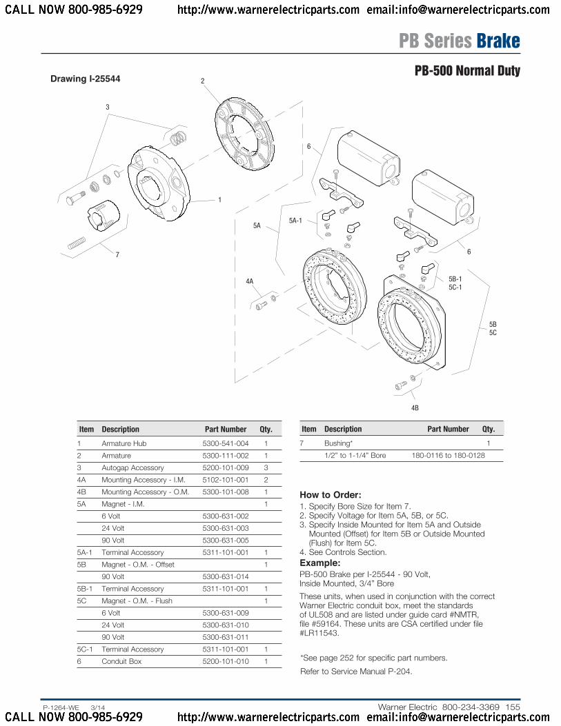
Drawing I-25544
How to Order:1. Specify Bore Size for Item 7.2. Specify Voltage for Item 5A, 5B, or 5C.3. Specify Inside Mounted for Item 5A and Outside
Mounted (Offset) for Item 5B or Outside Mounted (Flush) for Item 5C.
4. See Controls Section.Example:PB-500 Brake per I-25544 - 90 Volt, Inside Mounted, 3/4” BoreThese units, when used in conjunction with the correct Warner Electric conduit box, meet the standards of UL508 and are listed under guide card #NMTR, file #59164. These units are CSA certified under file #LR11543.
Item Description Part Number Qty.
1 Armature Hub 5300-541-004 12 Armature 5300-111-002 13 Autogap Accessory 5200-101-009 34A Mounting Accessory - I.M. 5102-101-001 24B Mounting Accessory - O.M. 5300-101-008 15A Magnet - I.M. 1 6 Volt 5300-631-002 24 Volt 5300-631-003 90 Volt 5300-631-0055A-1 Terminal Accessory 5311-101-001 15B Magnet - O.M. - Offset 1 90 Volt 5300-631-0145B-1 Terminal Accessory 5311-101-001 15C Magnet - O.M. - Flush 1 6 Volt 5300-631-009 24 Volt 5300-631-010 90 Volt 5300-631-0115C-1 Terminal Accessory 5311-101-001 16 Conduit Box 5200-101-010 1
Item Description Part Number Qty.
7 Bushing* 1 1/2” to 1-1/4” Bore 180-0116 to 180-0128
* See page 252 for specific part numbers. Refer to Service Manual P-204.
PB Series BrakePB-500 Normal Duty
CALL NOW 800-985-6929 http://www.warnerelectricparts.com email:[email protected]
CALL NOW 800-985-6929 http://www.warnerelectricparts.com email:[email protected]

156 Warner Electric 800-234-3369 ......P-1264-WE 3/14
Static Torque 40 lb. ft.
Maximum Speed 5,400 rpm
Standard Voltage D.C. 6, 24, 90
Outside Mounted Offset Backing Plate
Customer Shall Maintain:1. Squareness of brake mounting face with armature hub shaft
within .006 T.I.R.
2. Concentricity of brake mounting pilot diameter with ar ma ture hub shaft within .010 T.I.R.
Bore and Keyway Dimensions
Armature Keyway Bore Dia.
.751/.750 .187 x .093 .876/.875
.9385/.9375 1.001/1.000 1.126/1.125 .250 x .125 1.251/1.250
* Mounting holes are within .010 of true position relative to pilot diameter.
** Mounting holes are within .008 of true position relative to pilot diameter.
MAGNET VIEW(Inside & Outside Mounted)
ARMATURE VIEW
Outside Mounted Flush Backing Plate
5.140 Dia.
3.953
.515 Max.
8-32 UNC-3A
.390 Max.
3/8-16 UNC-2A
.062 When New
2.312 Max.
1.546
1.031
1.187
1.093
1.1711.203
.171 Max.
2.687 Dia.
2.0652.063
Pilot Dia.
1.281
2.390 Max.
.375
1.093
3.750
.208/.201 dia. (8) holes equally spaced on 2.375 dia.*
5.062
Removable plug in ends for 1/2”
conduit.
45°5 Sq.
6.5006.498
.399/.389 dia. (4) holes equally spaced on 5.875 dia.**
For Bore & Keyway sizes see chart below.
.468 Max.
2.234 Max.
1.125
.953
1.015
All dimensions are nominal unless otherwise noted.
Information on inertia and weights begins on page 239. Coil data is on pages 250 and 251.
PB Series BrakePB-500 Heavy Duty
CALL NOW 800-985-6929 http://www.warnerelectricparts.com email:[email protected]
CALL NOW 800-985-6929 http://www.warnerelectricparts.com email:[email protected]
157.P-1264-WE 3/14..... Warner Electric 800-234-3369
2(Shipped
Assembled) 2-1
2-3
2-4
2-5
2-21
5
4A4A-1
3A
3B
4B4C
5
4B-14C-1
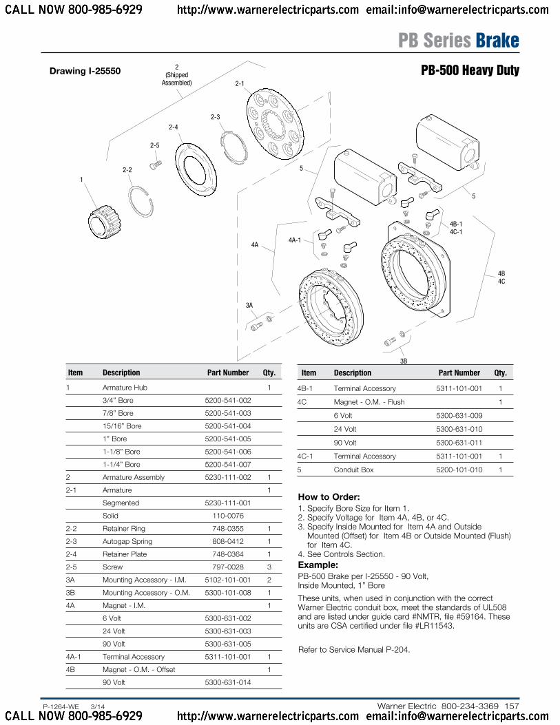
Drawing I-25550
How to Order:1. Specify Bore Size for Item 1.2. Specify Voltage for Item 4A, 4B, or 4C.3. Specify Inside Mounted for Item 4A and Outside
Mounted (Offset) for Item 4B or Outside Mounted (Flush) for Item 4C.
4. See Controls Section.Example:PB-500 Brake per I-25550 - 90 Volt, Inside Mounted, 1” Bore
These units, when used in conjunction with the correct Warner Electric conduit box, meet the standards of UL508 and are listed under guide card #NMTR, file #59164. These units are CSA certified under file #LR11543.
Item Description Part Number Qty.
1 Armature Hub 1
3/4” Bore 5200-541-002
7/8” Bore 5200-541-003
15/16” Bore 5200-541-004
1” Bore 5200-541-005
1-1/8” Bore 5200-541-006
1-1/4” Bore 5200-541-007
2 Armature Assembly 5230-111-002 1
2-1 Armature 1
Segmented 5230-111-001
Solid 110-0076
2-2 Retainer Ring 748-0355 1
2-3 Autogap Spring 808-0412 1
2-4 Retainer Plate 748-0364 1
2-5 Screw 797-0028 3
3A Mounting Accessory - I.M. 5102-101-001 2
3B Mounting Accessory - O.M. 5300-101-008 1
4A Magnet - I.M. 1
6 Volt 5300-631-002
24 Volt 5300-631-003
90 Volt 5300-631-005
4A-1 Terminal Accessory 5311-101-001 1
4B Magnet - O.M. - Offset 1
90 Volt 5300-631-014
Item Description Part Number Qty.
4B-1 Terminal Accessory 5311-101-001 1
4C Magnet - O.M. - Flush 1
6 Volt 5300-631-009
24 Volt 5300-631-010
90 Volt 5300-631-011
4C-1 Terminal Accessory 5311-101-001 1
5 Conduit Box 5200-101-010 1
Refer to Service Manual P-204.
PB Series BrakePB-500 Heavy Duty
CALL NOW 800-985-6929 http://www.warnerelectricparts.com email:[email protected]
CALL NOW 800-985-6929 http://www.warnerelectricparts.com email:[email protected]

158 Warner Electric 800-234-3369 ......P-1264-WE 3/14
Shaft Sizes .500 – 1.625
Static Torque 95 lb. ft.
Maximum Speed 3,600 rpm
Standard Voltage D.C. 6, 24, 90
HUB VIEW
Customer Shall Maintain:1. Squareness of brake mounting face with armature
hub shaft within .006 T.I.R.
2. Concentricity of brake mounting pilot diameter with armature hub shaft within .010 T.I.R.
* Mounting holes are within .010 of true position relative to pilot diameter.
MAGNET VIEW(Inside & Outside Mount ed)
See page 252 for details on Bushings.
8.0007.998
Pilot Dia.
5.765 Max.
45°
6.500 Sq.
.358/.338 dia. (4) holes equally spaced on 3.688 dia.*
.358/.338 dia. (4) holes equally spaced on 7.250 dia.*
Removable plug in ends for 1/2” conduit.
3.750
2.822/2.820 Pilot Dia.
Reversible Hub
5/16-18 UNC-3A
.062 Min.
Running Clearance
.546 Max.
.062 When New
.937
4.640
1
6.50 Dia.
4.375 Dia.
2.953 Max.1.265
1.796
1.546
All dimensions are nominal unless otherwise noted.
Information on inertia and weights begins on page 239. Coil data is on pages 250 and 251.
PB Series BrakePB-650
CALL NOW 800-985-6929 http://www.warnerelectricparts.com email:[email protected]
CALL NOW 800-985-6929 http://www.warnerelectricparts.com email:[email protected]

159.P-1264-WE 3/14..... Warner Electric 800-234-3369
7
7
5A-1
5A
5B-1
6
5B
32
1
4
Drawing I-25730
How to Order:1. Specify Bore Size for Item 2.2. Specify Voltage for Item 5.3. Specify Inside or Outside Mounted for Item 5.4. See Controls Section.Example:PB-650 Brake per I-25730 - 90 Volt, 1” Bore
These units, when used in conjunction with the correct Warner Electric conduit box, meet the standards of UL508 and are listed under guide card #NMTR, file #59164. These units are CSA certified under file #LR11543.
Item Description Part Number Qty.
1 Autogap Accessory 5181-101-010 4
2 Bushing* 1
1/2” to 1-5/8” Bore 180-0326 to 180-0344
3 Armature Hub 5207-541-002 1
4 Armature 5281-111-002 1
5A Magnet - Inside Mounted 1
6 Volt 5369-631-003
24 Volt 5369-631-006
90 Volt 5369-631-005
5A-1 Terminal Accessory 5311-101-001 1
5B Magnet - Outside Mounted 1
6 Volt 5369-631-009
24 Volt 5369-631-012
90 Volt 5369-631-011
5B-1 Terminal Accessory 5311-101-001 1
6 Mounting Accessory 5321-101-002 1
7 Conduit Box 5200-101-010 1
* See page 252 for specific part numbers.
Refer to Service Manual P-204.
PB Series BrakePB-650
CALL NOW 800-985-6929 http://www.warnerelectricparts.com email:[email protected]
CALL NOW 800-985-6929 http://www.warnerelectricparts.com email:[email protected]

160 Warner Electric 800-234-3369 ......P-1264-WE 3/14
PB Series BrakePB-825 Normal Duty
Shaft Size .500 – 1.625
Static Torque 125 lb. ft.
Maximum Speed 4,000 rpm
Standard Voltage D.C. 6, 24, 90
ARMATURE VIEW
Customer Shall Maintain:1. Squareness of magnet mounting face with armature shaft
within .006 T.I.R.
2. Concentricity of magnet mounting pilot diameter with armature shaft within .010 T.I.R.
MAGNET VIEW(Inside & Outside Mounted)
.062 Min.
Running Clearance
1.312
.562 Max.
5.656
.921
1.546
.562
.093 When New
5/16-18 UNC-3A
1.593
1.500
4.625 Dia.
8.656 Max. Dia.
3.609 Max.
2.562 Dia.
See page 252 for details on Bushings.
.358/.338 dia. (4) holes equally spaced on 8.875 dia.
3.503/3.501 Pilot Dia.
3.750
9.749/9.747 Pilot Dia.
.358/.338 dia. (6) holes equally spaced on 4.250 dia.
Removable plug in ends for 1/2” conduit.
6.812 Max.
All dimensions are nominal unless otherwise noted.
Information on inertia and weights begins on page 239. Coil data is on pages 250 and 251.
* Mounting holes are within .010 of true positioning relative to pilot diameter.
CALL NOW 800-985-6929 http://www.warnerelectricparts.com email:[email protected]
CALL NOW 800-985-6929 http://www.warnerelectricparts.com email:[email protected]

161.P-1264-WE 3/14..... Warner Electric 800-234-3369
Drawing I-25566
PB Series BrakePB-825 Normal Duty
2
1
3
4
7
6B-1
6B
7
6A-16A
5A5B
How to Order:1. Specify Bore Size for Item 1.2. Specify Inside Mounted for Items 5A and 6A or
Outside Mounted for Items 5B and 6B.3. Specify Voltage for Item 6A or 6B.4. See Controls Section.Example:PB-825 Brake per I-25566 - 90 Volt, Inside Mounted, 1” Bore
These units, when used in conjunction with the correct Warner Electric conduit box, meet the standards of UL508 and are listed under guide card #NMTR, file #59164. These units are CSA certified under file #LR11543.
Item De scrip tion Part Number Qty.
1 Bushing* 1
1/2” to 1-5/8” Bore 180-0131 to 180-0149
2 Armature Hub 540-0394 1
3 Armature 5301-111-018 1
4 Autogap Accessory 5201-101-008 3
5A Mounting Accessory - I.M. 5321-101-001 1
5B Mounting Accessory - O.M. 5321-101-002 1
6A Magnet - Inside Mounted 1
6 Volt 5311-631-002
24 Volt 5311-631-003
90 Volt 5311-631-004
†90 Volt LK Facing 5311-631-011
6A-1 Terminal Accessory 5311-101-001 1
6B Magnet, Outside Mounted 1
6 Volt 5311-631-007
24 Volt 5311-631-009
90 Volt 5311-631-008
†90 Volt LK Facing 5311-631-012
Item De scrip tion Part Number Qty.
6B-1 Terminal Accessory 5311-101-001 1
7 Conduit Box 5200-101-011 1
* See page 252 for specific part numbers.
Refer to Service Manual P-208.
† Optional LK facing available. For more information, see page 232.
CALL NOW 800-985-6929 http://www.warnerelectricparts.com email:[email protected]
CALL NOW 800-985-6929 http://www.warnerelectricparts.com email:[email protected]

162 Warner Electric 800-234-3369 ......P-1264-WE 3/14
Shaft Size .500 – 1.500
Static Torque 125 lb. ft.
Maximum Speed 4,000 rpm
Standard Voltage D.C. 6, 24, 90
ARMATURE VIEW
Customer Shall Maintain:1. Squareness of magnet mounting face with
armature shaft within .006 T.I.R.
2. Concentricity of magnet mounting pilot di am e ter with armature shaft within .010 T.I.R.
* Mounting holes are within .010 of true position relative to pilot diameter.
MAGNET VIEW(Inside & Outside Mounted)
See page 252 for details on Bushings.
2.500
.531 1.312
.562 Max.
5.656
.9211.546
5/16-18 UNC-3A
.062
.1568.656 Max. Dia.
1.250
1.765
2.718 Max..358/.338 dia. (4) holes equally spaced on 8.875 dia.*
3.503/3.501 Pilot Dia.
3.750
9.749/9.747 Pilot Dia.
.358/.338 dia. (6) holes equally spaced on 4.250 dia.*
Removable plug in ends for 1/2” conduit.
6.812 Max.
All dimensions are nominal unless otherwise noted.
Information on inertia and weights begins on page 239. Coil data is on pages 250 and 251.
PB Series BrakePB-825 Heavy Duty
CALL NOW 800-985-6929 http://www.warnerelectricparts.com email:[email protected]
CALL NOW 800-985-6929 http://www.warnerelectricparts.com email:[email protected]
163.P-1264-WE 3/14..... Warner Electric 800-234-3369
1
2
3
4
7
6B
6B-1 7
5B
6A6A-1
5A
3
6
5
6-1
7
1
2
4
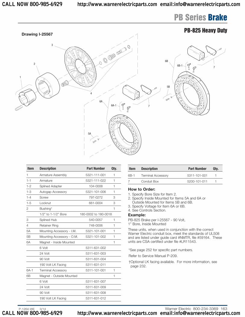
Drawing I-25567
How to Order:1. Specify Bore Size for Item 2.2. Specify Inside Mounted for Items 5A and 6A or
Outside Mounted for Items 5B and 6B.3. Specify Voltage for Item 6A or 6B.4. See Controls Section.Example:PB-825 Brake per I-25567 - 90 Volt, 1” Bore, Inside Mounted
These units, when used in conjunction with the correct Warner Electric conduit box, meet the standards of UL508 and are listed under guide card #NMTR, file #59164. These units are CSA certified under file #LR11543.
Item De scrip tion Part Number Qty.
1 Armature Assembly 5321-111-001 1
1-1 Armature 5321-111-022 1
1-2 Splined Adapter 104-0008 1
1-3 Autogap Accessory 5321-101-006 1
1-4 Screw 797-0272 3
1-5 Locknut 661-0004 3
2 Bushing* 1
1/2” to 1-1/2” Bore 180-0002 to 180-0018
3 Splined Hub 540-0057 1
4 Retainer Ring 748-0006 1
5A Mounting Accessory - I.M. 5321-101-001 1
5B Mounting Accessory - O.M. 5321-101-002 1
6A Magnet - Inside Mounted 1
6 Volt 5311-631-002
24 Volt 5311-631-003
90 Volt 5311-631-004
†90 Volt LK Facing 5311-631-011
6A-1 Terminal Accessory 5311-101-001 1
6B Magnet - Outside Mounted 1
6 Volt 5311-631-007
24 Volt 5311-631-009
90 Volt 5311-631-008
†90 Volt LK Facing 5311-631-012
Item De scrip tion Part Number Qty.
6B-1 Terminal Accessory 5311-101-001 1
7 Conduit Box 5200-101-011 1
* See page 252 for specific part numbers.
Refer to Service Manual P-209.
† Optional LK facing available. For more information, see page 232.
PB Series BrakePB-825 Heavy Duty
CALL NOW 800-985-6929 http://www.warnerelectricparts.com email:[email protected]
CALL NOW 800-985-6929 http://www.warnerelectricparts.com email:[email protected]

164 Warner Electric 800-234-3369 ......P-1264-WE 3/14
Shaft Size .500 – 2.500
Static Torque 240 lb. ft.
Maximum Speed 3,600 rpm
Standard Voltage D.C. 6, 24, 90
ARMATURE VIEW
Customer Shall Maintain:1. Squareness of magnet mounting face with armature shaft
within .006 T.I.R.
2. Concentricity of magnet mounting pilot diameter with armature shaft within .010 T.I.R.
MAGNET VIEW(Inside & Outside Mounted)
See page 252 for details on Bushings.
.358/.338 dia. (8) holes equally spaced on 10.625 dia.*
5.378/5.376 Pilot Dia.
3.750
11.500/11.498 Pilot Dia.
.358/.338 dia. (6) holes equally spaced on 6.125 dia.*
Removable plug in ends for 1/2” conduit.
7.687 Max.
.062 Min.
Running Clearance
1.453
.562 Max.
6.531
.921
1.546
.562
.093 When New
5/16-18 UNC-3A
1.906
1.750
6.250 Dia.
10.328 Max. Dia.
4.046 Max.
4.125 Dia.
All dimensions are nominal unless otherwise noted.
Information on inertia and weights begins on page 239. Coil data is on pages 250 and 251.
* Mounting holes are within .010 of true position relative to pilot diameter.
PB Series BrakePB-1000 Normal Duty
CALL NOW 800-985-6929 http://www.warnerelectricparts.com email:[email protected]
CALL NOW 800-985-6929 http://www.warnerelectricparts.com email:[email protected]

165.P-1264-WE 3/14..... Warner Electric 800-234-3369
2
1
3
4
7
6B-1
6B
7
6A-16A
5A5B
Drawing I-25586
How to Order:1. Specify Bore Size for Item 1.2. Specify Inside Mounted for Items 5A and 6A or Outside
Mounted for Items 5B and 6B.3. Specify Voltage for Item 6A or 6B.4. See Controls Section.Example:PB-1000 Brake per I-25586 - 90 Volt, Inside Mounted, 1” Bore
These units, when used in conjunction with the correct Warner Electric conduit box, meet the standards of UL508 and are listed under guide card #NMTR, file #59164. These units are CSA certified under file #LR11543.
Item De scrip tion Part Number Qty.
1 Bushing* 1
1/2” to 2-1/2” Bore 180-0185 to 180-0217
2 Armature Hub 540-0313 1
3 Armature 5302-111-013 1
4 Autogap Accessory 5201-101-008 3
5A Mounting Accessory - I.M. 5321-101-001 1
5B Mounting Accessory - O.M. 5321-101-002 2
6A Magnet - Inside Mounted 1
6 Volt 5312-631-004
24 Volt 5312-631-005
90 Volt 5312-631-006
†90 Volt LK Facing 5312-631-001
6A-1 Terminal Accessory 5311-101-001 1
6B Magnet, Outside Mounted 1
6 Volt 5312-631-011
24 Volt 5312-631-013
90 Volt 5312-631-012
†90 Volt LK Facing 5312-631-002
Item De scrip tion Part Number Qty.
6B-1 Terminal Accessory 5311-101-001 1
7 Conduit Box 5200-101-011 1
* See page 252 for specific part numbers.
Refer to Service Manual P-208.
† Optional LK facing available. For more information, see page 232.
PB Series BrakePB-1000 Normal Duty
CALL NOW 800-985-6929 http://www.warnerelectricparts.com email:[email protected]
CALL NOW 800-985-6929 http://www.warnerelectricparts.com email:[email protected]

166 Warner Electric 800-234-3369 ......P-1264-WE 3/14
Shaft Size .750 – 2.687
Static Torque 240 lb. ft.
Maximum Speed 3,600 rpm
Standard Voltage D.C. 6, 24, 90
ARMATURE VIEW
Customer Shall Maintain:1. Squareness of magnet mounting face with
armature shaft within .006 T.I.R.
2. Concentricity of magnet mounting pilot di am e ter with armature shaft within .010 T.I.R.
* Mounting holes are within .010 of true position relative to pilot diameter.
MAGNET VIEW(Inside & Outside Mounted)
4.093
.500 1.453
.562 Max.
6.531
.9211.546
5/16-18 UNC-3A
.062
.23410.328 Max. Dia.
2.500
2.687
3.921 Max.
See page 252 for details on Bushings.
.358/.338 dia. (8) holes equally spaced on
10.625 dia.
5.378/5.376 Pilot Dia.
3.750
11.500/11.498 Pilot Dia.
.358/.338 dia. (6) holes equally spaced on 6.125 dia.*
Removable plug in ends for 1/2” conduit.
7.687Max.
All dimensions are nominal unless otherwise noted.
Information on inertia and weights begins on page 239. Coil data is on pages 250 and 251.
PB Series BrakePB-1000 Heavy Duty
CALL NOW 800-985-6929 http://www.warnerelectricparts.com email:[email protected]
CALL NOW 800-985-6929 http://www.warnerelectricparts.com email:[email protected]

167.P-1264-WE 3/14..... Warner Electric 800-234-3369
1(Shipped
Assembled)
1-5
1-1
1-2
1-4
1-3
3
4
2
6A 6A-1
6B-1
7
7
6B
5B
5A
Drawing I-25587
How to Order:1. Specify Bore Size for Item 2.2. Specify Inside Mounted for Items 5A and 6A or Outside
Mounted for Items 5B and 6B.3. Specify Voltage for Item 6A or 6B.4. See Controls Section.Example:PB-1000 Brake per I-25587 - 90 Volt, 1-1/2” Bore, Inside Mounted
These units, when used in conjunction with the correct Warner Electric conduit box, meet the standards of UL508 and are listed under guide card #NMTR, file #59164. These units are CSA certified under file #LR11543.
Item De scrip tion Part Number Qty.
1 Armature Assembly 5322-111-002 1
1-1 Armature 5322-111-036 1
1-2 Splined Adapter 104-0009 1
1-3 Autogap Accessory 5322-101-004 1
1-4 Screw 797-0272 3
1-5 Locknut 661-0004 3
2 Bushing* 1
3/4” to 2-11/16” Bore 180-0026 to 180-0057
3 Splined Hub 540-0062 1
4 Retainer Ring 748-0007 1
5A Mounting Accessory - I.M. 5321-101-001 1
5B Mounting Accessory - O.M. 5321-101-002 2
6A Magnet - Inside Mounted 1
6 Volt 5312-631-004
24 Volt 5312-631-005
90 Volt 5312-631-006
†90 Volt LK Facing 5312-631-001
6A-1 Terminal Accessory 5311-101-001 1
6B Magnet - Outside Mounted 1
6 Volt 5312-631-011
24 Volt 5312-631-013
90 Volt 5312-631-012
†90 Volt LK Facing 5312-631-002
Item De scrip tion Part Number Qty.
6B-1 Terminal Accessory 5311-101-001 1
7 Conduit Box 5200-101-011 1
* See page 252 for specific part numbers.
Refer to Service Manual P-209.
† Optional LK facing available. For more information, see page 232.
PB Series BrakePB-1000 Heavy Duty
CALL NOW 800-985-6929 http://www.warnerelectricparts.com email:[email protected]
CALL NOW 800-985-6929 http://www.warnerelectricparts.com email:[email protected]

168 Warner Electric 800-234-3369 ......P-1264-WE 3/14
Shaft Size .937 – 3.000
Static Torque 465 lb. ft.
Maximum Speed 3,000 rpm
Standard Voltage D.C. 6, 24, 90
Customer Shall Maintain:1. Squareness of magnet mounting face with armature shaft
within .006 T.I.R.
2. Concentricity of magnet mounting pilot diameter with armature shaft within .010 T.I.R.
ARMATURE VIEW
MAGNET VIEW(Inside & Outside Mounted)
* Mounting holes are within .010 of true position relative to pilot diameter.
3
.593
.562 Max.
1.546
.921
.093 When New1.640
4.625 Dia.
.062 Min.
Running Clearance
7.5315/16-18 UNC-3A
12.671 Max. Dia.
6.875 Dia.
5.359 Max.
See page 252 for details on Bushings.
13.875/13.871 pilot dia.
Removable plug in ends for 1/2” conduit.
.358/.338 dia. (6) holes equally spaced on 7.250 dia.*
6.378/6.376 Pilot Dia.
3.750
.358/.338 dia. (8) holes equally spaced on 13.000 dia.*
8.687
All dimensions are nominal unless otherwise noted.
Information on inertia and weights begins on page 239. Coil data is on pages 250 and 251.
PB Series BrakePB-1225 Normal Duty
CALL NOW 800-985-6929 http://www.warnerelectricparts.com email:[email protected]
CALL NOW 800-985-6929 http://www.warnerelectricparts.com email:[email protected]

169.P-1264-WE 3/14..... Warner Electric 800-234-3369
1
2
3
4
7
6B
6B-1 7
5B
6A6A-1
5A
3
6
5
6-1
7
1
2
4
Drawing I-25606
How to Order:1. Specify Bore Size for Item 1.2. Specify Inside Mounted for Items 5A and 6A or Outside
Mounted for Items 5B and 6B.3. Specify Voltage for Item 6A or 6B.4. See Controls Section.Example:PB-1225 Brake per I-25606 - 90 Volt, 1” Bore, Inside Mounted
These units, when used in conjunction with the correct Warner Electric conduit box, meet the standards of UL508 and are listed under guide card #NMTR, file #59164. These units are CSA certified under file #LR11543.
Item De scrip tion Part Number Qty.
1 Bushing* 1
15/16” to 3” Bore 180-0262 to 180-0295
2 Armature Hub 540-0015 1
3 Armature 5303-111-009 1
4 Autogap Accessory 5201-101-008 4
5A Mounting Accessory - I.M. 5321-101-001 1
5B Mounting Accessory - O.M. 5321-101-002 2
6A Magnet - Inside Mounted 1
6 Volt 5313-631-005
24 Volt 5313-631-006
90 Volt 5313-631-007
†90 Volt 5313-631-001
6A-1 Terminal Accessory 5311-101-001 1
6B Magnet - Outside Mounted 1
6 Volt 5313-631-010
24 Volt 5313-631-012
90 Volt 5313-631-011
†90 Volt 5313-631-002
Item De scrip tion Part Number Qty.
6B-1 Terminal Accessory 5311-101-001 1
7 Conduit Box 5200-101-011 1
* See page 252 for specific part numbers.
Refer to Service Manual P-208.
† Optional LK facing available. For more information, see page 232.
PB Series BrakePB-1225 Normal Duty
CALL NOW 800-985-6929 http://www.warnerelectricparts.com email:[email protected]
CALL NOW 800-985-6929 http://www.warnerelectricparts.com email:[email protected]

170 Warner Electric 800-234-3369 ......P-1264-WE 3/14
Shaft Size .750 – 2.687
Static Torque 465 lb. ft.
Maximum Speed 3,000 rpm
Standard Voltage D.C. 6, 24, 90
Customer Shall Maintain:1. Squareness of magnet mounting face with
armature shaft within .006 T.I.R.
2. Concentricity of magnet mounting pilot diameter with armature shaft within .010 T.I.R.
ARMATURE VIEW
* Mounting holes are within .010 of true position relative to pilot diameter.
MAGNET VIEW
5/16-18 UNC-3A
.562 1.640
.562
7.531
.921
1.546
.062
.234
4.093 Dia.12.671
Max. Dia.
2.500
2.687
4.156 Max.
See page 252 for details on Bushings.
.358/.338 dia. (8) holes equally spaced on 13.000
dia.*
6.378/6.376 Pilot Dia.
3.750
13.875/12.871 Pilot Dia.
.358/.338 dia. (6) holes equally spaced on 7.250 dia.*
Removable plug in ends for 1/2” conduit.
8.687 Max.
All dimensions are nominal unless otherwise noted.
Information on inertia and weights begins on page 239. Coil data is on pages 250 and 251.
PB Series BrakePB-1225 Heavy Duty
CALL NOW 800-985-6929 http://www.warnerelectricparts.com email:[email protected]
CALL NOW 800-985-6929 http://www.warnerelectricparts.com email:[email protected]

171.P-1264-WE 3/14..... Warner Electric 800-234-3369
1(Shipped
Assembled)
1-5
1-11-2
1-4
1-3
3
4
2
6A
5A
7
7
6B
6A-1
5B
6B-1
How to Order:1. Specify Bore Size for Item 2.2. Specify Inside Mounted for Items 5A and 6A or Outside
Mounted for Items 5B and 6B.3. Specify Voltage for Item 6A or 6B.4. See Controls Section.Example:PB-1225 Clutch per I-25607 - 90 Volt, 1-1/2” Bore, Inside Mounted
These units, when used in conjunction with the correct Warner Electric conduit box, meet the standards of UL508 and are listed under guide card #NMTR, file #59164. These units are CSA certified under file #LR11543.
Drawing I-25607
Item Description Part Number Qty.
1 Armature & Splined Adapter 5323-111-001 1
1-1 Armature 5323-111-034 1
1-2 Splined Adapter 104-0010 1
1-3 Autogap Accessory 5323-101-002 1
1-4 Screw 797-0281 4
1-5 Locknut 661-0005 4
2 Bushing* 1
3/4” to 2-11/16” Bore 180-0026 to 180-0057
3 Splined Hub 540-0064 1
4 Retainer Ring 748-0005 1
5A Mounting Accessory - I.M. 5321-101-001 1
5B Mounting Accessory - O.M. 5321-101-002 2
6A Magnet - Inside Mounted 1
6 Volt 5313-631-005
24 Volt 5313-631-006
90 Volt 5313-631-007
†90 Volt 5313-631-001
6A-1 Terminal Accessory 5311-101-001 1
6B Magnet - Outside Mounted 1
6 Volt 5313-631-010
24 Volt 5313-631-012
90 Volt 5313-631-011
†90 Volt 5313-631-002
Item Description Part Number Qty.
6B-1 Terminal Accessory 5311-101-001 1
7 Conduit Box 5200-101-011 1
* See page 252 for specific part numbers.
Refer to Service Manual P-209.
† Optional LK facing available. For more information, see page 232.
PB Series BrakePB-1225 Heavy Duty
CALL NOW 800-985-6929 http://www.warnerelectricparts.com email:[email protected]
CALL NOW 800-985-6929 http://www.warnerelectricparts.com email:[email protected]

172 Warner Electric 800-234-3369 ......P-1264-WE 3/14
Shaft Size .937 – 3.000
Static Torque 700 lb. ft.
Maximum Speed 2,000 rpm
Standard Voltage D.C. 6, 24, 90
Customer Shall Maintain:1. Squareness of magnet mounting face with armature shaft
within .006 T.I.R.
2. Concentricity of magnet mounting pilot diameter with armature shaft within .010 T.I.R.
ARMATURE VIEW
MAGNET VIEW(Inside & Outside Mounted)
* Mounting holes are within .010 of true position relative to pilot diameter.
See page 252 for details on Bushings.
Removable plug in ends for 1/2” conduit.
.358/.338 dia. (12) holes equally spaced
on 9.750 dia.*
9.004/9.000 Pilot Dia.
3.750
3
.593
.562 Max.
1.546
.921
.093 When New1.750
7.093 Dia.
.062 Min.
Running Clearance
5/16-18 UNC-3A
6 Dia.
4.500 Max.
9.500
9.187
15.609 Max. Dia.
All dimensions are nominal unless otherwise noted.
Information on inertia and weights begins on page 239. Coil data is on pages 250 and 251.
PB Series BrakePB-1525 Normal Duty
CALL NOW 800-985-6929 http://www.warnerelectricparts.com email:[email protected]
CALL NOW 800-985-6929 http://www.warnerelectricparts.com email:[email protected]
173.P-1264-WE 3/14..... Warner Electric 800-234-3369
1
2
3
4
7
6B
6B-1 7
5B
6A6A-1
5A
3
6
5
6-1
7
1
2
4
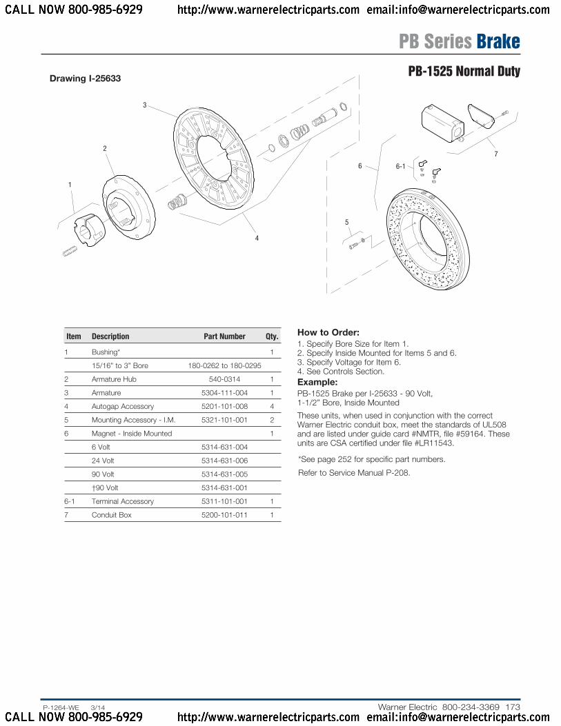
Drawing I-25633
How to Order:1. Specify Bore Size for Item 1.2. Specify Inside Mounted for Items 5 and 6.3. Specify Voltage for Item 6.4. See Controls Section.Example:PB-1525 Brake per I-25633 - 90 Volt, 1-1/2” Bore, Inside Mounted
These units, when used in conjunction with the correct Warner Electric conduit box, meet the standards of UL508 and are listed under guide card #NMTR, file #59164. These units are CSA certified under file #LR11543.
Item De scrip tion Part Number Qty.
1 Bushing* 1
15/16” to 3” Bore 180-0262 to 180-0295
2 Armature Hub 540-0314 1
3 Armature 5304-111-004 1
4 Autogap Accessory 5201-101-008 4
5 Mounting Accessory - I.M. 5321-101-001 2
6 Magnet - Inside Mounted 1
6 Volt 5314-631-004
24 Volt 5314-631-006
90 Volt 5314-631-005
†90 Volt 5314-631-001
6-1 Terminal Accessory 5311-101-001 1
7 Conduit Box 5200-101-011 1
* See page 252 for specific part numbers.
Refer to Service Manual P-208.
PB Series BrakePB-1525 Normal Duty
CALL NOW 800-985-6929 http://www.warnerelectricparts.com email:[email protected]
CALL NOW 800-985-6929 http://www.warnerelectricparts.com email:[email protected]

174 Warner Electric 800-234-3369 ......P-1264-WE 3/14
Shaft Size .750 – 2.687
Static Torque 700 lb. ft.
Maximum Speed 2,000 rpm
Standard Voltage D.C. 6, 24, 90
Customer Shall Maintain:1. Squareness of magnet mounting face with
armature shaft within .006 T.I.R.
2. Concentricity of magnet mounting pilot diameter with armature shaft within .010 T.I.R.
ARMATURE VIEW
* Mounting holes are within .010 of true position relative to pilot diameter.
MAGNET VIEW
See page 252 for details on Bushings.
9.004/9.000 Pilot Dia.
3.750
.358/.338 dia. (12) holes equally spaced on 9.750 dia.*
Removable plug in ends for 1/2” conduit.
10.343 Max.
All dimensions are nominal unless otherwise noted.
Information on inertia and weights begins on page 239. Coil data is on pages 250 and 251.
4.281 Max.
.562
.062
2.687
2.500
.234
4.093Dia.15.609
Max.Dia.
.562
9.187
5/16-18UNC-3A
.921
1.546
1.750
PB Series BrakePB-1525 Heavy Duty
CALL NOW 800-985-6929 http://www.warnerelectricparts.com email:[email protected]
CALL NOW 800-985-6929 http://www.warnerelectricparts.com email:[email protected]

175.P-1264-WE 3/14..... Warner Electric 800-234-3369
1(Shipped
Assembled)
1-6
1-11-2
1-3
1-4
1-5
2
3
4
6
5
6-1
7Drawing I-25634
How to Order:1. Specify Bore Size for Item 2.2. Specify Inside Mounted for Items 5 and 6.3. Specify Voltage for Item 6.4. See Controls Section.Example:PB-1525 Clutch per I-25634 - 90 Volt, 1-3/4” Bore
These units, when used in conjunction with the correct Warner Electric conduit box, meet the standards of UL508 and are listed under guide card #NMTR, file #59164. These units are CSA certified under file #LR11543.
Item Description Part Number Qty.
1 Armature & Splined Adapter 5324-111-001 1
1-1 Armature 5324-111-034 1
1-2 Splined Adapter 104-0011 1
1-3 Autogap Accessory 5323-101-002 1
1-4 Retainer Plate 686-0003 1
1-5 Screw 797-0272 8
1-6 Locknut 661-0004 8
2 Bushing* 1
3/4” to 2-11/16” Bore 180-0026 to 180-0057
3 Splined Hub 540-0064 1
4 Retainer Ring 748-0005 1
5 Mounting Accessory - I.M. 5321-101-001 2
6 Magnet - Inside Mounted 1
6 Volt 5314-631-004
24 Volt 5314-631-006
90 Volt 5314-631-005
†90 Volt 5314-631-001
6-1 Terminal Accessory 5311-101-001 1
7 Conduit Box 5200-101-011 1
* See page 252 for specific part numbers.
Refer to Service Manual P-209.
† Optional LK facing available. For more information, see page 232.
PB Series BrakePB-1525 Heavy Duty
CALL NOW 800-985-6929 http://www.warnerelectricparts.com email:[email protected]
CALL NOW 800-985-6929 http://www.warnerelectricparts.com email:[email protected]