Embed Size (px)
Citation preview
379
Chapter 9
Pb AND LBE CORROSION PROTECTION AT ELEVATED TEMPERATURES*
9.1 Introduction
Compatibility of material with liquid LBE is a key problem for LBE-cooled systems. Steels are attacked by dissolution of the components in LBE. Dissolution has to be minimised or, even better, entirely prevented for the structural cladding and target materials in contact with LBE. One measure that is widely being used for temperatures in the range up to 500�C is dissolution of oxygen in LBE until the oxygen content reaches a level that allows oxidation of the structural material but not oxidation of the LBE [Gromov, 2004], [Müller, 2000], [Benamati, 2000]. This method is described in Chapters 4 and 6 of this Handbook and will not be considered here. Nevertheless, the protection measures described in this chapter in most of the cases work also at oxygen potentials in the above given range or may be effective also at much lower potentials. In this chapter we are concerned with oxide coatings or alloys that develop slowly growing protective oxide scales by reaction of oxygen with alloyed stable oxide formers in the coating at the surface or into the bulk of the alloy material and are suitable for protection of highly loaded parts like claddings, wrappers and spacers at elevated temperatures above 500 up to 650�C [Müller, 2000], [Asher, 1977], [Deloffre, 2004], [Gorynin, 1999]. Other coatings or alloys that are based on refractory low soluble elements or on nitrides and carbides would require very low oxygen potentials to prevent oxidation of the material [Asher, 1977], [Benamati, 2004], [Seifert, 1961], [Block, 1977]. The following materials and modifications are discussed in this chapter for a successful application in liquid LBE systems.
1) Alloys with Al and Si that form thin stable oxide layers in LBE containing appropriate oxygen concentrations;
2) Coatings consisting of oxides, nitrides, carbides or alloys like FeCrAlY that form protective oxide layers in LBE containing oxygen;
3) Coatings with resistant metals with low solubility in LBE like W, Mo, Nb…;
4) Inhibitors like Zr dissolved in LBE that cause formation of a protective surface layer on the structural material.
The methods described in 1-3 divide into those that need oxygen concentrations in LBE in which oxides develop at the surface of structural material or that are high enough to prevent dissociation of oxide coatings and into those in which the oxygen concentration is low enough to prevent extensive oxidation of the protective compounds like nitrides and carbides and of the inhibitors dissolved in LBE. In case of low oxygen concentration we have to pay attention to its influence on the low temperature part of the reactor for which additional protection methods are not required in LBE with oxygen. The requirement of self healing of the protective layers has to be considered in any case.
* Chapter lead: Georg Müller (FZK, Germany). For additional contributors, please see the List of Contributors at the end of
this work.
380
The requirements on the properties of the material surface that contacts LBE can be summarised as follows:
� prevention of dissolution attack;
� tolerable oxidation rate during oxide scale formation;
� long-term, high-temperature stability of the system also under temporary abnormal conditions;
� tolerable influence of the coating and surface alloying process on he mechanical properties of the structural material;
� durability under irradiation;
� long-term mechanical stability of the surface coating and alloying layer;
� feasibility on an industrial level;
� self-healing ability of protective layers.
9.2 Methods of surface protection
9.2.1 Alloying of stable oxide formers
It is known from several examinations that Al and Si alloyed into the steel within the appropriate concentration range develop thin, stable and protective oxide scales by diffusion of Al or Si to the surface were they react with the oxygen dissolved in LBE. These scales are an effective barrier against diffusion of cations as well as of anions and prevent, thus, a fast growth of the scale that is often observed with the magnetite and spinel layers on FeCr steels. The slow growth of the oxide scale ensures a long time protection function without extensive steel oxidation. Breach of the scale is minimised and if it happens, self healing will occur by diffusion of the scale forming cations to the defect position which mainly consists of small fissures.
The main advantage of alloying Al or Si just into a thin surface layer is obvious. The thin surface layer will not influence the mechanical properties of the bulk material and the scale will have a good adhesion to the surface. Recently, there are some examinations reported on the suitability of Al alloyed into the surface of ferritic and austenitic steel for their protection against dissolution attack of LBE [Müller, 2000], [Deloffre, 2004]. Si was used up to now only as an addition to the bulk material with which a marked improvement of the corrosion resistance was attained [Gorynin, 1999], [Kurata, 2005], [Lim 2006]. It is alloyed into the steel during the industrial production process. An example is the Russian steel EI 852 containing 2 wt.% Si [Yachmenyor, 1999]. However, in principal, surface layers containing an alloy with Si should work as protective oxide scale formers as well.
The procedures for alloying Al into a steel surface layer reported up to date are:
� Melt alloying by melting of the surface covered with an Al foil or with precipitated Al by pulsed electrons beam of large diameter (GESA process) [Müller, 2005].
� Diffusion alloying that constitutes of three different procedures. The first is hot dipping of the steel into an Al melt with subsequent annealing [Glasbrenner, 1998]. The second heating of the steel covered by an Al foil above the melting point of Al [Heinzel, 2002]. The third is pack cementation [Deloffre 2004].

381
9.2.1.1 Alloying by the GESA process
GESA is a pulsed electron beam facility that consists of a high voltage generator with a pulse duration control unit, a multipoint explosive emission cathode, a controlling grid and an anode which form a triode [Engelko, 2001]. The kinetic energy of the beam electrons can be varied in the range of 50�150 keV, with a beam power density up to 2 MW/cm2 at the target and pulse duration up to 40 �s. The important parameters for the melting process, electron energy, power density and pulse duration can be chosen independent of each other. The energy density absorption of the target is up to 80 J/cm2, which is sufficient to melt metallic materials adiabatically up to a depth of 10-50 �m. The beam diameter is 6-10 cm and this is the area of surface melting by applying one single pulse. Due to the high cooling rate, on the order of 107 K/s, very fine grained or even amorphous structures develop during solidification of the molten surface layer. This is a suitable basis for the formation of protective oxide scales with good adhesion [Müller, 2005], [Engelko, 2001].
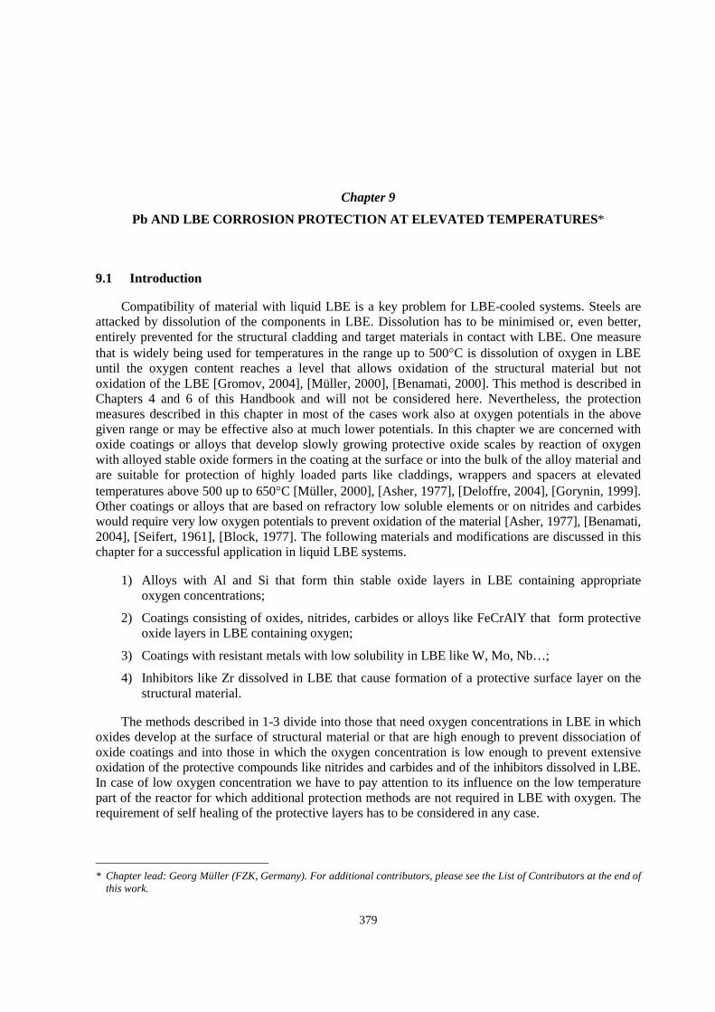
Surface alloying of the steel specimens was done by applying the electron pulse to the surface covered with an 18 �m thick Al foil [Müller, 2005]. During surface melting 20-25% of the aluminium is dissolved in the melt layer, the remainder evaporates. The micrographic cross-section and the Al-concentration profile perpendicular to the surface is shown in Figure 9.2.1. The analysis shows that Al penetrates into the steel within the molten surface layer. Profile A was obtained with an 18 �m Al-foil by applying just one electron pulse and profile B with a second pulse after attaching a new Al-foil. When an additional pulse is applied to a surface with a B-profile without replacing the Al-foil, profile C is obtained, which is almost constant up to a depth of 15 �m. The concentration profiles are not typical for a diffusion process, but for a distribution by turbulences in the melt. The obtained structure consists of two phases, which contain different Al concentrations (4-10 wt.%) but have the same Cr content. One phase corresponds to Al dissolved in Fe, �-Fe(Al), the other is FeAl [Müller, 2000].
Figure 9.2.1. Micrographic cross-section and Al concentration profiles after alloying Al into an OPTIFER IVc surface with 0.45 MJ/m2
A: 1 pulse with 18 µm Al foil; B: 2 pulses, each one with 18 �m Al foil; C: 2 pulses, first with, second without 18 �m Al foil [Müller, 2005]
Corrosion experiments with alloyed steels show that 4 wt.% Al is high enough to achieve selective alumina scale formation [Asher, 1977]. For concentrations above 20 wt.%, however, the Al activity gets too high and dissolution attack can occur [Müller, 2002].
In a few cases single areas appear after surface alloying in which with Al concentrations are below 4 wt.% because of incomplete overlapping of alloyed surface regions. In such places the steel
Al alloyed layer
Steel
382
would develop normal magnetite and spinel layers like the unalloyed steel surface because the Al content is too low for selective oxidation and alumina formation on the surface. Those defects have to be avoided by sufficient overlapping of the electron beam areas.
Since, structural parts that are exposed to high temperatures, including fuel cladding wrappers and spacers, have to be protected by the alumina layers at the surface, a new GESA IV facility has been constructed which allows surface alloying of tubes with small diameters by employing a cylindrical cathode [Weisenburger, 2005]. A tube length of 32 cm is alloyed with one single pulse on the whole tube and circumferential overlapping on the surface is avoided.
9.2.1.2 Diffusion alloying processes
As opposed to the GESA process the diffusion alloying processes create Al alloys by interdiffusion between the steel matrix and the Al at the surface which is in most cases in a liquid state. The time for interdiffusion should be long enough to lower the Al activity to a value for which no rapid dissolution in LBE takes place. We refer here to three processes: hot dipping, pack cementation and liquefying of an Al foil at the surface.
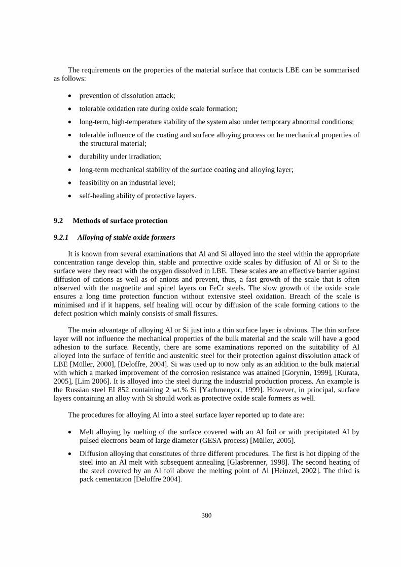
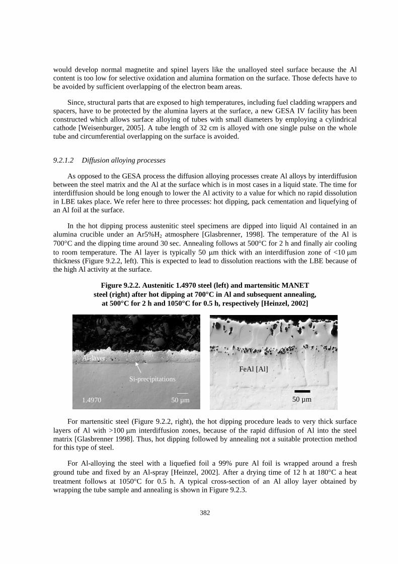
In the hot dipping process austenitic steel specimens are dipped into liquid Al contained in an alumina crucible under an Ar5%H2 atmosphere [Glasbrenner, 1998]. The temperature of the Al is 700�C and the dipping time around 30 sec. Annealing follows at 500�C for 2 h and finally air cooling to room temperature. The Al layer is typically 50 �m thick with an interdiffusion zone of <10 �m thickness (Figure 9.2.2, left). This is expected to lead to dissolution reactions with the LBE because of the high Al activity at the surface.
Figure 9.2.2. Austenitic 1.4970 steel (left) and martensitic MANET steel (right) after hot dipping at 700�C in Al and subsequent annealing,
at 500�C for 2 h and 1050�C for 0.5 h, respectively [Heinzel, 2002]
50 µm 1.4970
Al-layer
Si-precipitations
For martensitic steel (Figure 9.2.2, right), the hot dipping procedure leads to very thick surface layers of Al with >100 �m interdiffusion zones, because of the rapid diffusion of Al into the steel matrix [Glasbrenner 1998]. Thus, hot dipping followed by annealing not a suitable protection method for this type of steel.
For Al-alloying the steel with a liquefied foil a 99% pure Al foil is wrapped around a fresh ground tube and fixed by an Al-spray [Heinzel, 2002]. After a drying time of 12 h at 180�C a heat treatment follows at 1050�C for 0.5 h. A typical cross-section of an Al alloy layer obtained by wrapping the tube sample and annealing is shown in Figure 9.2.3.
FeAl [Al]
50 µm
383
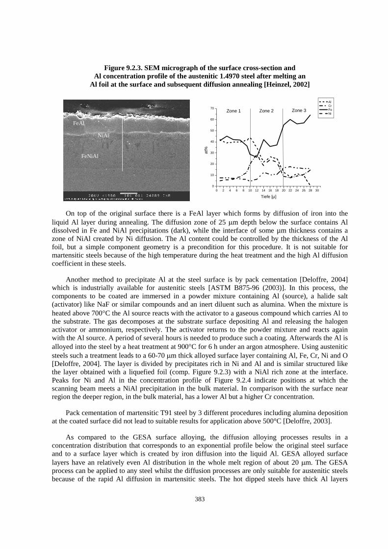
Figure 9.2.3. SEM micrograph of the surface cross-section and Al concentration profile of the austenitic 1.4970 steel after melting an
Al foil at the surface and subsequent diffusion annealing [Heinzel, 2002]
FeAl
NiAl
FeNiAl
0 2 4 6 8 10 12 14 16 18 20 22 24 26 28 30
0
10
20
30
40
50
60
70Zone 3Zone 2Zone 1
Tiefe [µ]
at%
Al Cr Fe Ni
On top of the original surface there is a FeAl layer which forms by diffusion of iron into the liquid Al layer during annealing. The diffusion zone of 25 �m depth below the surface contains Al dissolved in Fe and NiAl precipitations (dark), while the interface of some µm thickness contains a zone of NiAl created by Ni diffusion. The Al content could be controlled by the thickness of the Al foil, but a simple component geometry is a precondition for this procedure. It is not suitable for martensitic steels because of the high temperature during the heat treatment and the high Al diffusion coefficient in these steels.
Another method to precipitate Al at the steel surface is by pack cementation [Deloffre, 2004] which is industrially available for austenitic steels [ASTM B875-96 (2003)]. In this process, the components to be coated are immersed in a powder mixture containing Al (source), a halide salt (activator) like NaF or similar compounds and an inert diluent such as alumina. When the mixture is heated above 700�C the Al source reacts with the activator to a gaseous compound which carries Al to the substrate. The gas decomposes at the substrate surface depositing Al and releasing the halogen activator or ammonium, respectively. The activator returns to the powder mixture and reacts again with the Al source. A period of several hours is needed to produce such a coating. Afterwards the Al is alloyed into the steel by a heat treatment at 900�C for 6 h under an argon atmosphere. Using austenitic steels such a treatment leads to a 60-70 �m thick alloyed surface layer containing Al, Fe, Cr, Ni and O [Deloffre, 2004]. The layer is divided by precipitates rich in Ni and Al and is similar structured like the layer obtained with a liquefied foil (comp. Figure 9.2.3) with a NiAl rich zone at the interface. Peaks for Ni and Al in the concentration profile of Figure 9.2.4 indicate positions at which the scanning beam meets a NiAl precipitation in the bulk material. In comparison with the surface near region the deeper region, in the bulk material, has a lower Al but a higher Cr concentration.
Pack cementation of martensitic T91 steel by 3 different procedures including alumina deposition at the coated surface did not lead to suitable results for application above 500°C [Deloffre, 2003].
As compared to the GESA surface alloying, the diffusion alloying processes results in a concentration distribution that corresponds to an exponential profile below the original steel surface and to a surface layer which is created by iron diffusion into the liquid Al. GESA alloyed surface layers have an relatively even Al distribution in the whole melt region of about 20 �m. The GESA process can be applied to any steel whilst the diffusion processes are only suitable for austenitic steels because of the rapid Al diffusion in martensitic steels. The hot dipped steels have thick Al layers

384
Figure 9.2.4. Typical cross-section of pack cemented 316 steel and concentration profile obtained by a scan perpendicular to the surface
0 20 40 60 80 100 120 140 160
0
50
100
150
200
250
Zone 2 Zone 3bulk
units
depth [µm]
Al Fe Cr Ni
Zone 1FeAl
NiAl precipitation
NiAl rich zone
which also after annealing have a high Al activity that leads to dissolution attack in LBE [Glasbrenner, 1998]. Alloying by a liquefied Al foil has, compared to hot-dipping, the advantage that the thickness of the Al layer can be controlled by the thickness of the foil [Heinzel, 2002].
9.2.2 Corrosion-resistant coatings
Instead of surface alloying resistant metals, alloys or compounds can be precipitated on the steel surface [Ballinger, 2004]. Resistant metals like W, Mo, Nb or alloys of these metals require a clean environment with very low oxygen activity to prevent oxidation. The metals themselves have a low solubility and are stable in LBE at lower oxygen activities. Alloys like the superalloy MCrAlY [Nicholls, 2003] gain protective behaviour by forming a stable, dense oxide scale on the surface. These alloys require an oxygen activity that causes oxide scale formation and that keeps the scales stable and allows their self-healing. Coatings consisting of resistant compounds like oxides, carbides or nitrides will generally not possess self-healing properties. They must have long time stability and good adhesion to the steel surface which is not easily being achieved.
9.2.2.1 FeCrAlY coatings
MCrAlY coatings (M=Fe, Ni, Co or NiCo) are widely applied for first and second stage turbine blades as corrosion resistant overlays or as bond-coats for use with thermal barrier coatings [Nicholls, 2003]. The corrosion resistance is based on the ability to form alumina layers due to selective oxidation. The coating could be applied by a number of processes like physical vapour deposition (PVD), air plasma spraying (APS) or vacuum plasma spraying (VPS), but the most common is the low pressure plasma spraying (LPPS). Figure 9.2.5 left side shows a cross-section of a cladding tube with a ~20 �m LPPS FeCrAlY coating1. Coatings with Co could not be used because of the activation in a reactor and those with Ni not because of the high solubility of Ni in Pb and PbBi.
The coating has a rough surface because of the relatively large spray droplets, contains pores and also the adhesion on the bulk material is not perfect. To exclude these uncertainties, the coatings can be treated using the GESA melting process. Experiments with GESA show that a GESA treatment
1 Coating by Sulzer, Wohlen, Switzerland.
NiAl
FeAl
385
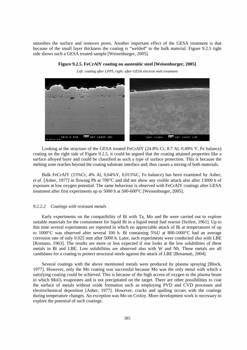
smoothes the surface and removes pores. Another important effect of the GESA treatment is that because of the small layer thickness the coating is “welded” to the bulk material. Figure 9.2.5 right side shows such a GESA treated sample [Weisenburger, 2005].
Figure 9.2.5. FeCrAlY coating on austenitic steel [Weisenburger, 2005]
Left: coating after LPPS, right: after GESA electron melt treatment
Looking at the structure of the GESA treated FeCrAlY (24.8% Cr, 8.7 Al, 0.49% Y, Fe balance) coating on the right side of Figure 9.2.5, it could be argued that the coating attained properties like a surface alloyed layer and could be classified as such a type of surface protection. This is because the melting zone reaches beyond the coating substrate interface and, thus causes a mixing of both materials.
Bulk FeCrAlY (15%Cr, 4% Al, 0,64%Y, 0,015%C, Fe balance) has been examined by Asher, et al. [Asher, 1977] in flowing Pb at 700�C and did not show any visible attack also after 13000 h of exposure at low oxygen potential. The same behaviour is observed with FeCrAlY coatings after GESA treatment after first experiments up to 5000 h at 500-600�C [Weisenburger, 2005].
9.2.2.2 Coatings with resistant metals
Early experiments on the compatibility of Bi with Ta, Mo and Be were carried out to explore suitable materials for the containment for liquid Bi in a liquid metal fuel reactor [Seifert, 1961]. Up to this time several experiments are reported in which no appreciable attack of Bi at temperatures of up to 1000�C was observed after several 100 h. Bi containing 5%U at 800-1000�C had an average corrosion rate of only 0.025 mm after 5000 h. Later, such experiments were conducted also with LBE [Romano, 1963]. The results are more or less expected if one looks at the low solubilities of these metals in Bi and LBE. Low solubilities are observed also with W and Nb. These metals are all candidates for a coating to protect structural steels against the attack of LBE [Benamati, 2004].
Several coatings with the above mentioned metals were produced by plasma spraying [Block, 1977]. However, only the Mo coating was successful because Mo was the only metal with which a satisfying coating could be achieved. This is because of the high access of oxygen to the plasma beam in which MoO3 evaporates and is not precipitated on the target. There are other possibilities to coat the surface of metals without oxide formation such as employing PVD and CVD processes and electrochemical deposition [Asher, 1977]. However, cracks and spalling occurs with the coatings during temperature changes. An exception was Mo on Croloy. More development work is necessary to explore the potential of such coatings.
386
It is obvious that dense coatings with metals of low solubility offer a good protection against LBE especially if the oxygen potential of the LBE is below that of the metal oxide formation. If this is not the case, stable oxide layer formation on the metal surface is necessary for an effective protection.
9.2.2.3 Oxide, carbide and nitride coatings
Oxide, carbide and nitride coatings are widely used in industrial applications and the technique of their precipitation on metal surfaces is well developed, e.g. for the hot sections of gas turbines for numerous cases of corrosion protection and wear resistance. These materials isolate the steel from aggressive media but have poor strength and ductility and cannot be used as a structural material itself. As a protective coating, however, they allow application of steels with high strength and ductility which, if unprotected, are exposed to strong dissolution attack by LBE. The disadvantage of the coating concept is, however, that the coatings have no self healing ability and a fracturing or spallation of the coating would lead to a direct dissolution attack by the LBE of the uncovered part of the steel. This is the main problem with oxide, carbide and nitride coatings and it is enhanced by the fact that bad adherence may exist as well as stresses because of the differences in the thermal expansion. TiN, CrN and diamond like carbon coatings (DLC) of good adherence were obtained from Ion Bond AG, Olten, Switzerland, and employed for examination in the LBE of the CORWETT loop under stress at temperature of 350�C [Glasbrenner, 2004].
There are some attempts to employ ceramic coatings for the protection of steels against LBE. They include nitrides and borides of Ti and Zr, carbides of W, aluminium-magnesium spinel [Romano, 1963] and ZrO2 + Y2O3 [Asher, 1977]. The layers are, however, not dense enough to inhibit cation and anion diffusion and are subjected to cracking and spalling. More development work is necessary.
9.2.3 Corrosion inhibitors in LBE
By definition inhibitors are substances which, when added to a chemical system in small amounts (in the order of only 10–3 wt.%), interact with the reactants to reduce the reaction rate. By this definition oxygen dissolved in LBE acts as such an inhibitor through the formation of a stable oxide film reducing the dissolution rate. Additions of other elements such as Zr or Ti to low oxygen LBE may provide an inhibitive effect, also [Hodge, 1970], [Shmatko, 1998]. A possible mechanism explaining this kinetic phenomenon is that Zr (or Ti) promotes the formation/creation of a thin, compact, adherent protective nitride layer being insoluble in the LBE deoxidised at first with Mg (approx. 5 � 10–2 wt.%) acting as a getter [Hodge, 1970]. If enough nitrogen is present in the steel, protective TiN or ZrN films will form at first. After consuming all the nitrogen (most structural steels contain nitrogen in the order of several ppm), in the second step TiC and ZrC films will start to grow [Ilincev, 2002]. The existence of such films was proofed experimentally. Synergetic effects have not been reported. Creating protective films is also affected by the heat treatment. Fine nitrides are more uniformly distributed, e.g. nitrogen can diffuse faster. An indirect proof of the TiC, TiN or ZrC, ZrN, role is that inhibition is most effective on steels which are rich both C and N and, at the same time, characterised by a low content of Cr, Mo, V and other carbide and nitride-forming elements [Ilincev, 2002].
Inhibited corrosion rates of low-alloyed steels were examined as a function of temperature [Weeks, 1958] in comparison to reference samples without an inhibitor postulating that Zr/Ti solubilities in LBE are the most important factors affecting inhibition. Diffusion is of secondary importance. Stainless chrome, chrome–nickel and low-alloyed steels stabilised with strong carbide- and nitride-forming elements do not form protective films and thus they must corrode fast as in cases if no inhibitor was used (tests with reference samples).
387
Determining an optimal (in any case low!) concentration of the inhibitive additives and maintaining it at this low level during the whole loop operation and explaining the role of particular alloying elements in steels on the formation and mechanical stability of protective inhibitive films is still an obvious need. However, long-term tests on large devices are required before the inhibition method could be utilised on a large scale [Park, 2000].
Proper mixing procedures which assure a homogenous distribution of the inhibitor within the LM as well as maintaining its amount at a constant level during the whole loop operation are crucial here.
9.3 Corrosion examinations on alloys and coatings
9.3.1 Surface alloys
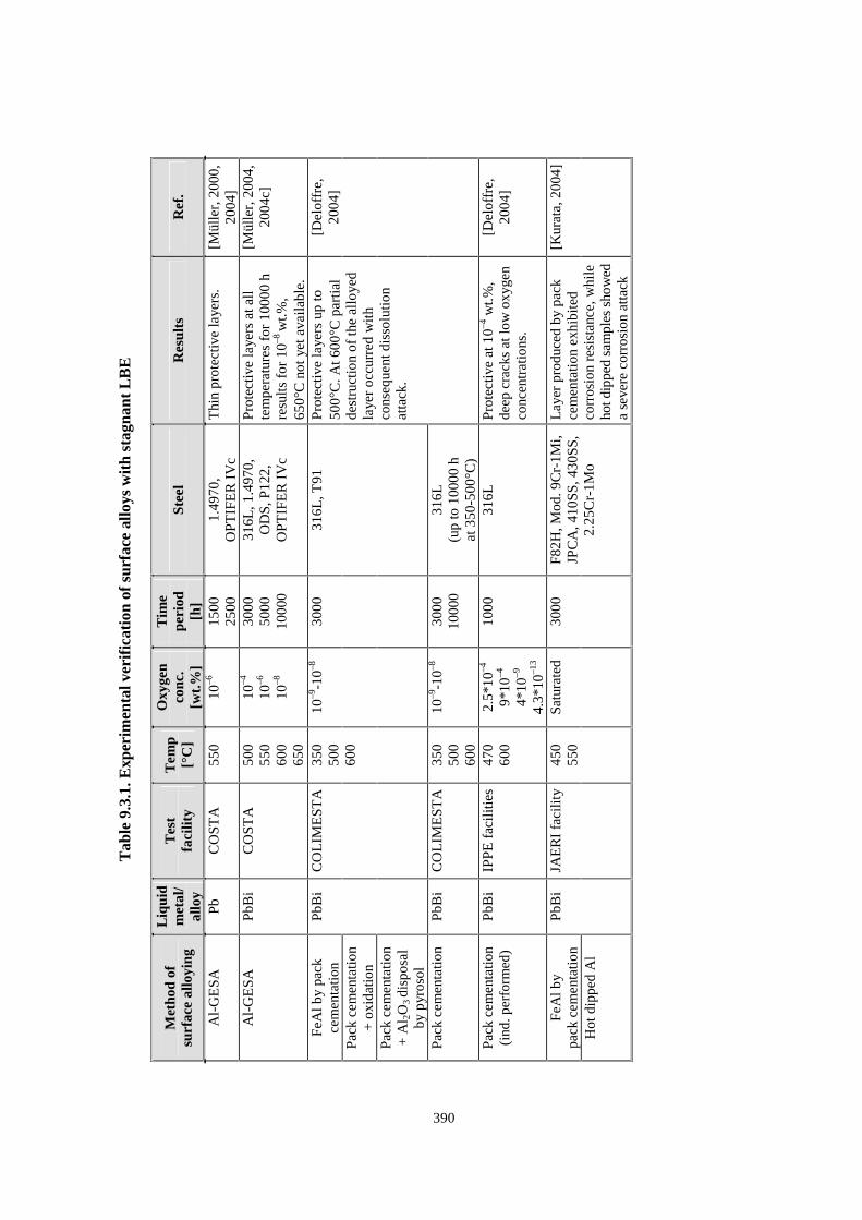
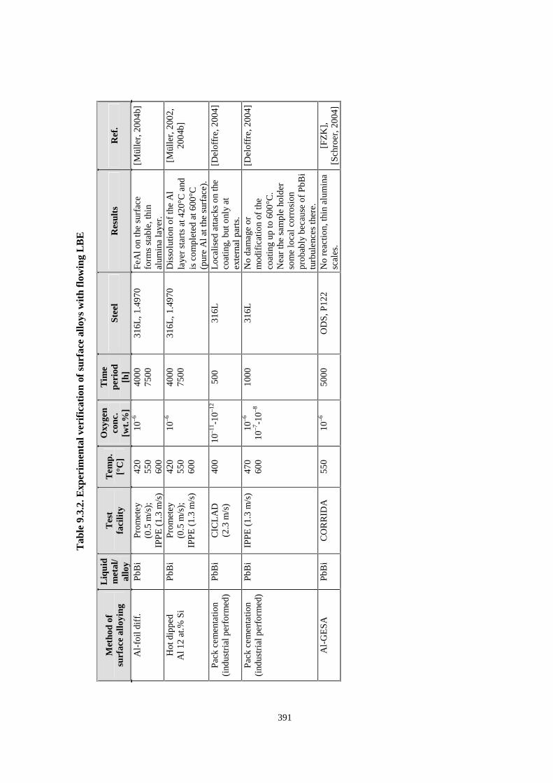
Several experiments with surface alloyed steel have been conducted in stagnant and flowing LBE with oxygen concentrations in the range of 10–4-10–13 wt.%. The experimental conditions and results are listed in Tables 9.3.1 and 9.3.2.
As shown in Tables 9.3.1 and 9.3.2 most of the experiments were conducted with Al surface alloys produced by melt alloying with the GESA process and by pack cementation. In all GESA alloyed specimens stable protective oxide scales with no attack of LBE up to 650�C and 10000 h are observed. This concerns austenitic as well as martensitic steels in an environment of stagnant LBE with 10–4 and 10–6 wt.% oxygen.
The same positive result was obtained for alloys produced by pack cementation up to 600�C after 3000 h of exposure to stagnant LBE with about 10–4 wt.% oxygen. Examination of pack cementation alloys in stagnant LBE with oxygen concentrations below 10–8 wt.%, however, resulted in dissolution attack at temperatures above 500�C after 1000 and 3000 h, respectively.
Looking at the experiments in the Prometey IPPE and CICLAD loops one can see satisfying protection behaviour of the Al-surface-alloyed steels at an oxygen concentration of 10–6 wt.% up to 600�C [Müller, 2002, 2004], [Deloffre 2004] with the exception of the hot dipped steel, in which dissolution attack starts at 420�C because of the high Al activity that leads to strong dissolution attack.
Some local corrosion processes in the pack cementation specimen near the sample holder are believed to be caused by LBE turbulences at the specimen tube holder [Deloffre, 2004].
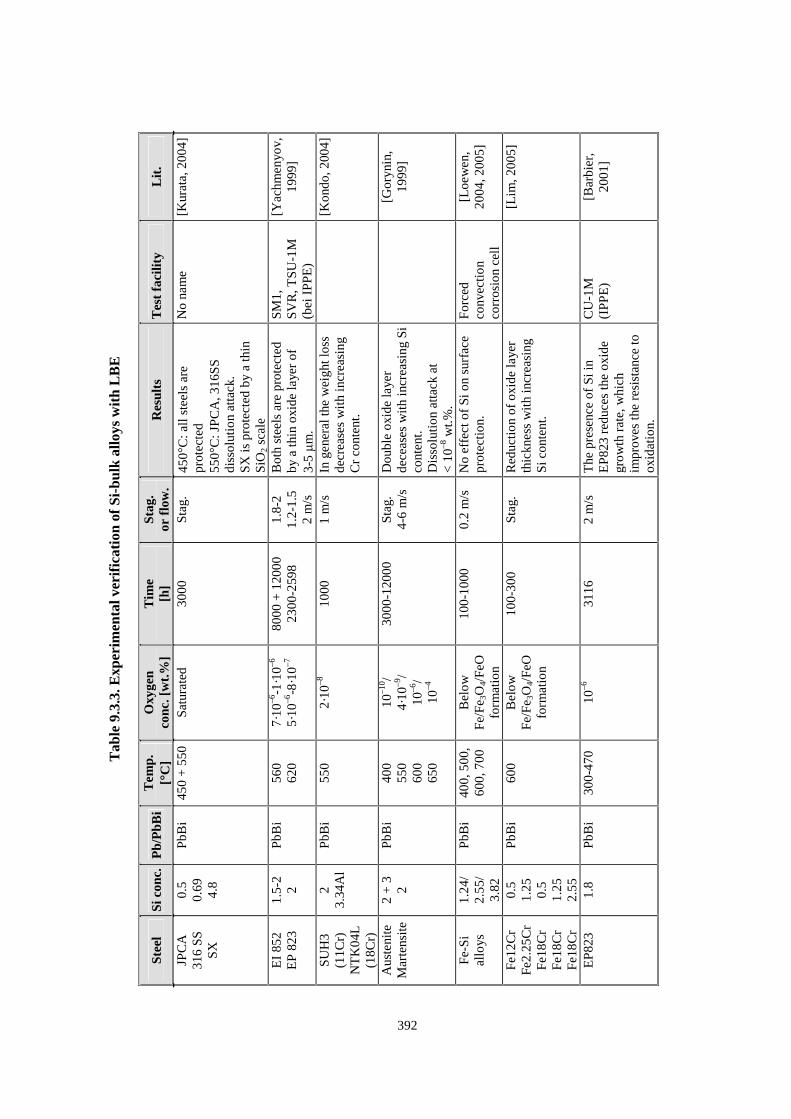
9.3.2 Bulk alloys
Numerous experiments are conducted on steels alloyed with Si especially in the low concentration region up to 3 wt.%. The first experiments reported on austenitic steels containing up to 3 wt.% Si result in a low oxide scale thickness which levels up to 20 �m after 12000 h of exposure to LBE in a narrow region around 10–6 wt.% oxygen at 550�C [Gorynin, 1999]. The same steel without Si addition reaches an oxide thickness > 80 �m at these conditions. Another experiment with the steel SX (Fe, 17.6Cr 4.8Si) at 550�C shows a thin protective SiO2 scale at the surface after 3000 h in LBE with saturated oxygen content [Kurata, 2005]. Although this is a desired result, the way can not be followed because above 1.5-2 wt.% of Si the steel impact strength decreases rapidly due to embrittlement [Gorynin, 1999] and the resistance against radiation damage decreases.
388
Systematic investigations of the influence of Si on surface protection in LBE with oxygen activities below that for the Fe/Fe3O4/FeO stability range showed the importance of Cr concentrations in steel [Ballinger, 2003], [Lim 2006]. While Si concentrations of up to 3.8 wt.% have no positive effect on protection of low Cr martensitic steel, in 12-18 Cr martensitic steel the thickness of the protective spinel oxide scale is drastically decreased with increasing Si concentration up to 2.25 wt.%. It is believed that a network of precipitated SiO2 and Fe2SiO4 localised beneath the Cr rich oxide layer forms a barrier for diffusion of oxygen into the steel matrix [Lim, 2006].
A review on the experiments conducted is given in Table 9.3.3.
9.3.3 Coatings
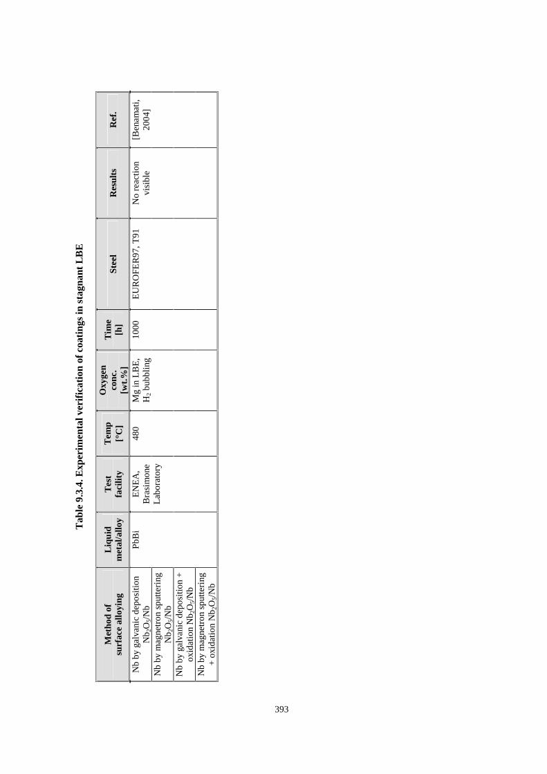
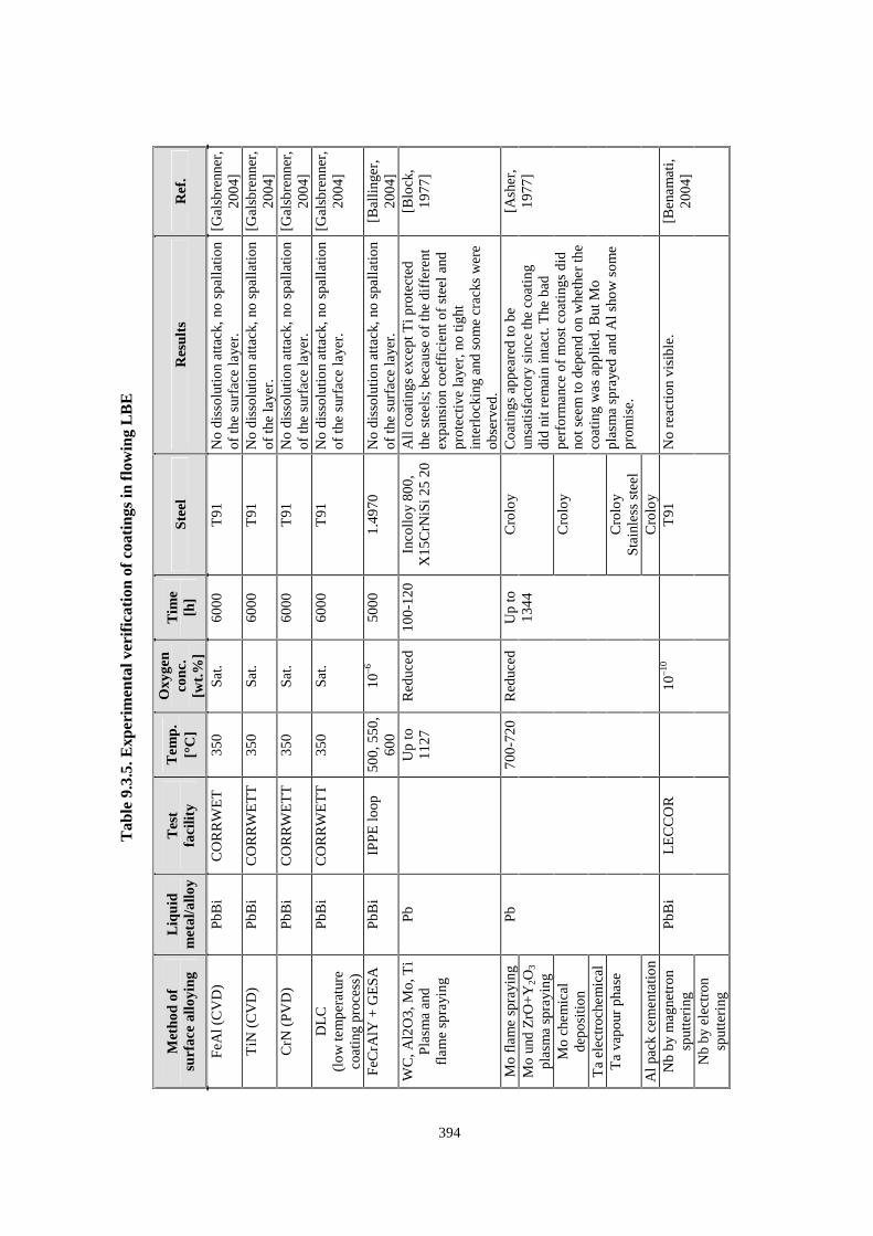
Only few experiments with protective coatings have been conducted. The experiments in stagnant LBE are listed in Table 9.3.4 and those in flowing LBE are listed in Table 9.3.5.
The test with the FeCrAlY coating with GESA treatment was carried out under controlled oxygen concentration, and did not lead to a dissolution attack after 5000 h at 550 and 650�C in LBE with 10–6 wt.% oxygen [Weisenburger, 2005]. The alumina scale on the surface was very thin and did not show visible scale growth.
Nb coated on the surface of EUROFER97 and T91 steel did not react with LBE under strongly reducing conditions at 480�C during 1000 h [Benamati, 2004]. This is due to the fact that the solubility of Nb in LBE is very low. Nb coating with an Nb2O5 oxide scale produced by Nb anodisation is also resistant against attack by LBE in the temperature range of 450-500�C. Appropriate oxygen potential control is required in this case to prevent Nb2O5 decomposition. Experiments with W in LBE indicate that W as a coating is not compatible if the LBE is saturated with oxygen. A 50 �m thick reaction layer of WO3 and Pb-W complex oxide covers the surface after 2000 h at 520�C [Benamati, 2004]. The same is expected to happen for Mo in this environment. Other experiments with coatings in LBE with no defined oxygen concentration level result in bad performance of the metal coatings, also of W and Ta, independent of the productions process by plasma spraying, flame spraying, CVD or electrochemical deposition with the exception of Mo plasma sprayed on Croloy [Asher, 1977]. The other coatings suffered from cracking and spalling.
Experiments have been carried out at the relatively low temperature of 350�C to examine the influence of stresses on TiN, DLC and CrN coatings. They show diminishing of the protection behaviour as opposed to the unstressed conditions. Only TiN was not influenced by stresses and showed neither dissolution attack nor formation of cracks [Glasbrenner, 2004, 2005]. The results obtained in the experiments can be described as follows:
� Static load on CrN caused corrosion attack by LBE. This was not the case when the exposure tests were carried out without any static pressure. Hence, the stress has a negative influence to the compatibility of this layer.
� There seems to be no chemical interaction between LBE and the unstressed DLC layer. But at a static stress of 150 MPa a degradation of the layer and change in thickness occurred. The compression seems to be more effective than tension. In the areas with destroyed layer parts the specimen was affected by LBE.
Exposure of TiN coated specimens up to 6000 h in LBE revealed the most promising results. This coating is not influenced by LBE with and without static stresses up to 200 MPa.
389
9.4 Concluding remarks
Application of LBE with an oxygen concentration that ensures formation of magnetite on the steel surface is the first choice for realisation of a LBE cooled nuclear installation. The concentration must, however, be lower than that at which precipitation of PbO takes place. This would provide protective conditions especially for the low temperature parts. However at elevated temperatures this method of steel protection fails because of extensive steel corrosion by oxidation without sufficient prevention of dissolution attack by LBE. Therefore, structural parts exposed to high thermal loads like cladding tubes, which could reach temperatures above 500�C, need additional protection measures. It can be concluded at this point that austenitic and martensitic steel alloyed by GESA and austenitic steels alloyed by the pack cementation process and by foil melting fulfil as well as steels alloyed with Si the requirements concerning corrosion protection against the LBE attack up to 600�C if the oxygen concentration in LBE is between 10–4 and 10–6 wt.%. From the results obtained with pack cemented steels in LBE containing less than 10–8 wt.% oxygen, however, it seems, that the oxygen activity above 500�C gets low enough to allow dissolution attack on FeAl before a stable alumina scale is developed because the proceeding of this process depends strongly on the oxygen concentration in the surrounding LBE.
Alloying Al into the surface causes very thin, slowly growing oxide scales that prevent steel oxidation and dissolution attack by LBE. Additionally, the self healing in case of oxide scale defects that may occur during thermo cycling is expected.
Successful methods of alloying Al into the steel surface are:
� melt alloying by GESA and pack cementation for austenitic steels;
� FeCrAlY coating with subsequent alloying by GESA for martensitic and austenitic steels as well.
It is of advantage that the pack cementation and the FeCrAlY coating processes are already performed on an industrial level. Therefore, this process should be favoured. This holds as well for steels alloyed with Si during fabrication.
Coatings with metals of low solubility in LBE, e.g. Mo, and of nitrides and carbides should be excluded because they would require very low oxygen activities and would leave uncoated low temperature parts unprotected.
The use of oxide coatings, e.g. alumina, which would allow application of LBE with appropriate oxygen concentration must be excluded because of expected adhesion problems and because of absence of a self healing of defects.
For a final judgement of the suggested protection processes additional examination is required on:
� long-term behaviour;
� self healing properties;
� mechanical properties;
� behaviour under irradiation;
� influence of fretting on the protective layer.
Tab
le 9
.3.1
. Exp
erim
enta
l ver
ific
atio
n of
sur
face
allo
ys w
ith
stag
nant
LB
E
Met
hod
of
surf
ace
allo
ying
Liq
uid
met
al/
allo
y
Tes
t
faci
lity
Tem
p
[°C
]
Oxy
gen
conc
. [w
t.%
]
Tim
e
peri
od
[h]
Stee
l R
esul
ts
Ref
.
Al-
GE
SA
P
b C
OST
A
550
10–6
15
00
2500
1.
4970
, O
PTIF
ER
IV
c T
hin
prot
ectiv
e la
yers
. [M
ülle
r, 2
000,
20
04]
Al-
GE
SA
P
bBi
CO
STA
50
0 55
0 60
0 65
0
10–4
10
–6
10–8
3000
50
00
1000
0
316L
, 1.4
970,
O
DS,
P12
2,
OPT
IFE
R I
Vc
Pro
tect
ive
laye
rs a
t all
tem
pera
ture
s fo
r 10
000
h re
sult
s fo
r 10
–8 w
t.%,
650�
C n
ot y
et a
vaila
ble.
[Mül
ler,
200
4,
2004
c]
FeA
l by
pack
ce
men
tati
on
Pac
k ce
men
tati
on
+ o
xida
tion
Pac
k ce
men
tati
on
+ A
l 2O
3 di
spos
al
by p
yros
ol
PbB
i C
OL
IME
STA
35
0 50
0 60
0
10–9
-10–8
30
00
316L
, T91
Pac
k ce
men
tati
on
PbB
i C
OL
IME
STA
35
0 50
0 60
0
10–9
-10–8
30
00
1000
0 31
6L
(up
to 1
0000
h
at 3
50-5
00°C
)
Pro
tect
ive
laye
rs u
p to
50
0�C
. At 6
00�C
par
tial
dest
ruct
ion
of th
e al
loye
d la
yer
occu
rred
wit
h co
nseq
uent
dis
solu
tion
atta
ck.
[Del
offr
e,
2004
]
Pac
k ce
men
tati
on
(ind
. per
form
ed)
PbB
i IP
PE
fac
ilitie
s 47
0 60
0 2.
5*10
–4
9*10
–4
4*10
–9
4.3*
10–1
3
1000
31
6L
Pro
tect
ive
at 1
0–4 w
t.%,
deep
cra
cks
at lo
w o
xyge
n co
ncen
trat
ions
.
[Del
offr
e,
2004
]
FeA
l by
pack
cem
enta
tion
H
ot d
ippe
d A
l
PbB
i JA
ER
I fa
cilit
y 45
0 55
0 Sa
tura
ted
3000
F8
2H, M
od. 9
Cr-
1Mi,
JPC
A, 4
10SS
, 430
SS,
2.25
Cr-
1Mo
Lay
er p
rodu
ced
by p
ack
cem
enta
tion
exhi
bite
d co
rros
ion
resi
stan
ce, w
hile
ho
t dip
ped
sam
ples
sho
wed
a
seve
re c
orro
sion
att
ack
[Kur
ata,
200
4]
390
Tab
le 9
.3.2
. Exp
erim
enta
l ver
ific
atio
n of
sur
face
allo
ys w
ith
flow
ing
LB
E
Met
hod
of
surf
ace
allo
ying
Liq
uid
met
al/
allo
y
Tes
t
faci
lity
Tem
p.
[°C
]
Oxy
gen
conc
. [w
t.%
]
Tim
e
peri
od
[h]
Stee
l R
esul
ts
Ref
.
Al-
foil
diff
. P
bBi
Pro
met
ey
(0.5
m/s
);
IPP
E (
1.3
m/s
)
420
550
600
10–6
40
00
7500
31
6L, 1
.497
0 Fe
Al o
n th
e su
rfac
e fo
rms
stab
le, t
hin
alum
ina
laye
r.
[Mül
ler,
200
4b]
Hot
dip
ped
A
l 12
at.%
Si
PbB
i P
rom
etey
(0
.5 m
/s);
IP
PE
(1.
3 m
/s)
420
550
600
10–6
40
00
7500
31
6L, 1
.497
0 D
isso
lutio
n of
the
Al
laye
r st
arts
at 4
20�C
and
is
com
plet
ed a
t 600
�C
(pur
e A
l at t
he s
urfa
ce).
[Mül
ler,
200
2,
2004
b]
Pac
k ce
men
tati
on
(ind
ustr
ial p
erfo
rmed
) P
bBi
CIC
LA
D
(2.3
m/s
) 40
0 10
–11 -1
0–12
500
316L
L
ocal
ised
atta
cks
on th
e co
atin
g, b
ut o
nly
at
exte
rnal
par
ts.
[Del
offr
e, 2
004]
Pac
k ce
men
tati
on
(ind
ustr
ial p
erfo
rmed
) P
bBi
IPP
E (
1.3
m/s
) 47
0 60
0 10
–6
10–7
-10–8
10
00
316L
N
o da
mag
e or
m
odif
icat
ion
of th
e co
atin
g up
to 6
00�C
. N
ear
the
sam
ple
hold
er
som
e lo
cal c
orro
sion
pr
obab
ly b
ecau
se o
f P
bBi
turb
ulen
ces
ther
e.
[Del
offr
e, 2
004]
Al-
GE
SA
P
bBi
CO
RR
IDA
55
0 10
–6
5000
O
DS,
P12
2 N
o re
acti
on, t
hin
alum
ina
scal
es.
[FZ
K],
[S
chro
er, 2
004]
391
Tab
le 9
.3.3
. Exp
erim
enta
l ver
ific
atio
n of
Si-
bulk
allo
ys w
ith
LB
E
Stee
l Si
con
c.
Pb/
PbB
i T
emp.
[�
C]
Oxy
gen
conc
. [w
t.%
] T
ime
[h
] St
ag.
or f
low
. R
esul
ts
Tes
t fa
cilit
y L
it.
JPC
A
316
SS
SX
0.5
0.69
4.
8
PbB
i 45
0 +
550
Sa
tura
ted
3000
St
ag.
450�
C: a
ll s
teel
s ar
e pr
otec
ted
550�
C: J
PC
A, 3
16S
S
diss
olut
ion
atta
ck.
SX
is p
rote
cted
by
a th
in
SiO
2 sc
ale
No
nam
e [K
urat
a, 2
004]
EI
852
EP
823
1.
5-2
2 P
bBi
560
620
7·10
–6-1
·10–6
5·
10–6
-8·1
0–7
8000
+ 1
2000
23
00-2
598
1.8-
2 1.
2-1.
5 2
m/s
Bot
h st
eels
are
pro
tect
ed
by a
thin
oxi
de la
yer
of
3-5 �m
.
SM1,
SV
R, T
SU-1
M
(bei
IPP
E)
[Yac
hmen
yov,
19
99]
SUH
3 (1
1Cr)
N
TK
04L
(1
8Cr)
2 3.
34A
l P
bBi
550
2·10
–8
1000
1
m/s
In
gen
eral
the
wei
ght l
oss
decr
ease
s w
ith
incr
easi
ng
Cr
cont
ent.
[K
ondo
, 200
4]
Aus
teni
te
Mar
tens
ite
2 +
3
2 P
bBi
400
550
600
650
10–1
0 / 4·
10–9
/ 10
–6/
10–4
3000
-120
00
Stag
. 4-
6 m
/s
Dou
ble
oxid
e la
yer
dece
ases
wit
h in
crea
sing
Si
cont
ent.
Dis
solu
tion
atta
ck a
t <
10–8
wt.%
.
[G
oryn
in,
1999
]
Fe-S
i al
loys
1.
24/
2.55
/ 3.
82
PbB
i 40
0, 5
00,
600,
700
B
elow
Fe
/Fe 3
O4/
FeO
fo
rmat
ion
100-
1000
0.
2 m
/s
No
effe
ct o
f Si
on
surf
ace
prot
ectio
n.
For
ced
conv
ecti
on
corr
osio
n ce
ll
[Loe
wen
, 20
04, 2
005]
Fe12
Cr
Fe2.
25C
r Fe
18C
r Fe
18C
r Fe
18C
r
0.5
1.25
0.
5 1.
25
2.55
PbB
i 60
0 B
elow
Fe
/Fe 3
O4/
FeO
fo
rmat
ion
100-
300
Stag
. R
educ
tion
of o
xide
laye
r th
ickn
ess
wit
h in
crea
sing
Si
con
tent
.
[L
im, 2
005]
EP
823
1.8
PbB
i 30
0-47
0 10
–6
3116
2
m/s
T
he p
rese
nce
of S
i in
EP
823
redu
ces
the
oxid
e gr
owth
rat
e, w
hich
im
prov
es th
e re
sist
ance
to
oxid
atio
n.
CU
-1M
(I
PPE
) [B
arbi
er,
2001
]
392
Tab
le 9
.3.4
. Exp
erim
enta
l ver
ific
atio
n of
coa
ting
s in
sta
gnan
t L
BE
Met
hod
of
surf
ace
allo
ying
L
iqui
d m
etal
/allo
y T
est
fa
cilit
y T
emp
[�C
]
Oxy
gen
conc
. [w
t.%
]
Tim
e
[h]
Stee
l R
esul
ts
Ref
.
Nb
by g
alva
nic
depo
sitio
n N
b 2O
5/N
b N
b by
mag
netr
on s
putte
ring
N
b 2O
5/N
b N
b by
gal
vani
c de
posi
tion
+
oxid
atio
n N
b 2O
5/N
b N
b by
mag
netr
on s
putte
ring
+
oxi
datio
n N
b 2O
5/N
b
PbB
i E
NE
A,
Bra
sim
one
Lab
orat
ory
480
Mg
in L
BE
, H
2 bu
bblin
g 10
00
EU
RO
FER
97, T
91
No
reac
tion
vi
sibl
e [B
enam
ati,
2004
]
393
Tab
le 9
.3.5
. Exp
erim
enta
l ver
ific
atio
n of
coa
ting
s in
flo
win
g L
BE
Met
hod
of
surf
ace
allo
ying
L
iqui
d m
etal
/allo
y T
est
fa
cilit
y T
emp.
[�
C]
Oxy
gen
conc
. [w
t.%
]
Tim
e [h
] St
eel
Res
ults
R
ef.
FeA
l (C
VD
) P
bBi
CO
RR
WE
T
350
Sat.
6000
T
91
No
diss
olut
ion
atta
ck, n
o sp
alla
tion
of th
e su
rfac
e la
yer.
[G
alsb
renn
er,
2004
] T
iN (
CV
D)
PbB
i C
OR
RW
ET
T
350
Sat.
6000
T
91
No
diss
olut
ion
atta
ck, n
o sp
alla
tion
of th
e la
yer.
[G
alsb
renn
er,
2004
] C
rN (
PV
D)
PbB
i C
OR
RW
ET
T
350
Sat.
6000
T
91
No
diss
olut
ion
atta
ck, n
o sp
alla
tion
of th
e su
rfac
e la
yer.
[G
alsb
renn
er,
2004
] D
LC
(l
ow te
mpe
ratu
re
coat
ing
proc
ess)
PbB
i C
OR
RW
ET
T
350
Sat.
6000
T
91
No
diss
olut
ion
atta
ck, n
o sp
alla
tion
of th
e su
rfac
e la
yer.
[ G
alsb
renn
er,
2004
]
FeC
rAlY
+ G
ES
A
PbB
i IP
PE
loop
50
0, 5
50,
600
10–6
50
00
1.49
70
No
diss
olut
ion
atta
ck, n
o sp
alla
tion
of th
e su
rfac
e la
yer.
[B
allin
ger,
20
04]
WC
, Al2
O3,
Mo,
Ti
Pla
sma
and
fl
ame
spra
ying
Pb
U
p to
11
27
Red
uced
10
0-12
0 In
collo
y 80
0,
X15
CrN
iSi 2
5 20
A
ll c
oati
ngs
exce
pt T
i pro
tect
ed
the
stee
ls; b
ecau
se o
f th
e di
ffer
ent
expa
nsio
n co
effi
cien
t of
stee
l and
pr
otec
tive
laye
r, n
o tig
ht
inte
rloc
king
and
som
e cr
acks
wer
e ob
serv
ed.
[Blo
ck,
1977
]
Mo
flam
e sp
rayi
ng
Mo
und
ZrO
+Y
2O3
plas
ma
spra
ying
Cro
loy
Mo
chem
ical
de
posi
tion
Ta
elec
troc
hem
ical
Cro
loy
Ta
vapo
ur p
hase
C
rolo
y St
ainl
ess
stee
l A
l pac
k ce
men
tati
on
Pb
70
0-72
0 R
educ
ed
Up
to
1344
Cro
loy
Coa
ting
s ap
pear
ed to
be
unsa
tisf
acto
ry s
ince
the
coat
ing
di
d ni
t rem
ain
inta
ct. T
he b
ad
perf
orm
ance
of
mos
t coa
ting
s di
d no
t see
m to
dep
end
on w
heth
er th
e co
atin
g w
as a
pplie
d. B
ut M
o pl
asm
a sp
raye
d an
d A
l sho
w s
ome
prom
ise.
[Ash
er,
1977
]
Nb
by m
agne
tron
sp
utte
ring
N
b by
ele
ctro
n sp
utte
ring
PbB
i L
EC
CO
R
10
–10
T
91
No
reac
tion
vis
ible
. [B
enam
ati,
2004
]
394
395
REFERENCES
Asher, R.C., D. Davies, S.A. Beetham (1977), Corrosion Science, Vol. 17, pp. 545-557, Pergamon Press.
Ballinger, R.G., J. Lim (2004), Nuclear Technology, 147 (3) 418-435.
Benamati, G., P. Buttol, V. Imbeni, C. Martini, G. Palombarini (2000), Journal of Nuclear Materials, Vol. 279, pp. 308-316.
Benamati, G., (Ed.) (2004), Final Scientific Technical Report TECLA, European Community, 5th R&D Framework Programme.
Block, F.R., J. Schneider, G. Stolzenberg (1977), Archiv Eisenhüttenwesen, 48, No. 6, June, pp. 359-364.
Barbier, F., A. Rusanov (2001), J. of. Nucl. Mater., 296, 231-236.
Deloffre, Ph., F. Balbaud-Célérier, A. Terlain (2004), Journal of Nuclear Materials, Vol. 335, pp. 180-184.
Deloffre, Ph., F. Herbert, C. Delisle, C. Blanc, S. Poissonnet (2003), Behavior of the Aluminized T91 Martensitic Steel and 316 Austenitic Steel on Contact with Static and Dynamic Pb-Bi, Rapport Technique SCCME, RT-SCCME 584.
Engelko, V., B. Yatsenko, G. Müller, H. Bluhm (2001), Vacuum, Vol. 62, pp. 211-216.
FZK/JNC report, forthcoming.
Glasbrenner, H., J. Konys, K. Stein-Fechner, O. Wedemeyer (1998), Journal of Nuclear Materials, Vol. 258, p. 1173.
Glasbrenner, H., A. Bollhalder, F. Gröschel, K. Thomsen (2004), D. Viol, PSI Report TM-34-04-04.
Glasbrenner, H., F. Gröschel (2005), presented during IWSMT-7, Thun, Switzerland, 29 May-3 June.
Gorynin, I.V., G-P. Karzov, V.G. Markov, V.S. Lavrukhin, V.A. Yakovlev (1998), Proceedings of the Meeting on Problems of Structural Materials Corrosion in Lead-bismuth Coolant, Heavy Liquid Metal Coolants in Nuclear Technology (HLMC-98), Vol. 1, Obninsk, Russia, 5-9 October 1999, pp. 120-132.
Gromov, B.F., Yu.I. Orlov, P.V. Martinov, V.A. Gulevsky (1999), Proceedings of the Meeting on Problems of Structural Materials Corrosion in Lead-bismuth Coolant, Heavy Liquid Metal Coolants in Nuclear Technology (HLMC-98), Vol. 1, Obninsk, Russia, 5-9 October 1999, p. 87.
Heinzel, A. (2002), Dissertation Universität Karlsruhe, Report FZKA 6823 (2003).
396
Hodge, R.I., R.B. Turner, J.L. Platten (1970), “A 5000 h Test of a Lead-bismuth Circuit Constructed in Steel and Niobium”, in “Corrosion by Liquid Metals” AIME Proc. 1969, J.E. Draley, J.R. Weeks (eds.), Plenum Press, NY.
Ilincev, G. (2002), Nuclear Engineering and Design, 217, Issues 1-2, pp. 167-177.
Knebel, J.U., X. Cheng, C.H. Lefhalm, G. Müller, G. Schumacher, J. Konys, H. Glasbrenner (2000), Nuclear Engineering and Design, 2002, pp. 279-296.
Kondo, M., S. Yoshida, A. Yamada, M. Takahashi, N. Sawada, K. Hata, “Experimental Studies on Pb-Bi Flow Technology and Steel Compatibility with Pb-Bi”, ICONE 12-49285.
Kurata, Y., M. Furukawa (2004), J. of Nucl. Mater., 325, 217-222.
Kurata, Y., M. Furukawa, S. Saito (2004), Journal of Nuclear Materials, Vol. 335, pp. 501-507.
Kurata, Y., M. Furukawa, S. Saito (2005), J. of Nucl. Mater, 343, 333-340.
Lim, J. (2006), PhD thesis (MIT 2005), Massachusetts Institute of Technology, Feb. 2006.
Loewen, E.P. (2005), “Corrosion Studies in Support of Lead-bismuth Cooled FBRs”, Progress in Nuclear Energy, Vol. 47, No. 1-4, pp. 561-586.
Loewen, E.P., R. Balinger, J. Lim (2004), “Corrosion Studies in Support of a Medium-power Lead-alloy-cooled Reactor”, Nucl. Tech., Vol. 147, pp 436-456.
Müller, G., G. Schumacher, F. Zimmermann (2000), Journal of Nuclear Materials, Vol. 278, pp. 85-95.
Müller, G., A. Heinzel, J. Konys, G. Schumacher, A. Weisenburger, F. Zimmermann, V. Engelko, A. Rusanov, V. Markov (2002), Journal of Nuclear Materials, Vol. 301, pp. 40-46.
Müller, G., G. Schumacher, A. Weisenburger, A. Heinzel, F. Zimmermann, T. Furukawa, K. Aoto (2004), JNC TY9400 2003-026.
Müller, G., A. Heinzel, J. Konys, G. Schumacher, A. Weisenburger, F. Zimmermann, V. Engelko, A. Rusanov, V. Markov (2004b), Journal of Nuclear Materials, Vol. 335, pp. 163-168.
Müller, G., G. Schumacher, A. Weisenburger, A. Heinzel, F. Zimmermann, T. Furukawa, K. Aoto (2004c), JNC TY9400 2003-028.
Müller, G., V. Engelko, A. Weisenburger, A. Heinzel (2005), Vacuum, 77, pp. 469-474.
Nicholls, J.R. (2003), MRS bulletin, Vol. 28, No. 9, p. 659.
Park, J.J., D.P. Butt, C.A. Beard (2000), Nuclear Engineering and Design, Vol. 196, pp. 315-325.
Romano, A.J., C.J. Klamut, D.H. Gurinsky (1963), The Investigation of Container Materials for Bi and Pb Alloys, Part I, Thermal Convection Loops, Brookhaven National Laboratory Report BNL-811 (T-313)
Schroer, C., Z. Voss, O. Wedemeyer, J. Novotny, J. Konys, A. Heinzel, A. Weisenburger, G. Müller, T. Furukawa, K. Aoto (2004), JNC TY9400 2004-023.