Embed Size (px)
Citation preview

Patterns and security technologies for co-extraction of coaland gas in deep mines without entry pillars
Nong Zhang1 • Fei Xue1 • Nianchao Zhang1 • Xiaowei Feng1
Received: 20 March 2015 / Revised: 1 April 2015 / Accepted: 3 April 2015 / Published online: 9 May 2015
� The Author(s) 2015. This article is published with open access at Springerlink.com
Abstract Retaining gob-side entryways and the stability of gas drainage boreholes are two essential techniques in the co-
extraction of coal and gas without entry pillars (CECGWEP). However, retained entryways located in deep coal mines are
hard to maintain, especially for constructing boreholes in confined spaces, owing to major deformations. Consequently, it is
difficult to drill boreholes and maintain their stability, which therefore cannot guarantee the effectiveness of gas drainage.
This paper presents three measures for conducting CECGWEP in deep mines on the basis of effective space in retained
entryways for gas drainage. They are combinations of retaining roadways and face-lagging inclined boreholes, retaining
roadways and face-advancing inclined boreholes, and retaining roadways and high return airway inclined boreholes.
Several essential techniques are suggested to improve the maintenance of retained entryways and the stabilization of
boreholes. For the particular cases considered in this study, two field trials have verified the latter two measures from the
results obtained from the faces 1111(1) and 11112(1) in the Zhuji Mine. The results indicate that these models can
effectively solve the problems in deep mines. The maximum gas drainage flow for a single hole can reach 8.1 m3/min and
the effective drainage distance can be extended up to 150 m or more.
Keywords Retaining gob-side entryways � Stability of borehole � Gas pressure relief � Co-extraction of coal and gas
without the entry pillar
1 Introduction
As an associated product of coal production, gas is an in-
novative clean energy and high-class chemical material,
although it may cause major life threatening disasters in
collieries and increase the greenhouse effect in the atmo-
sphere (Zhang et al. 2013; Xue et al. 2014). The gas can be
scientifically used and serve as one of the most important
consequential energy resources in the 21st-century (Yuan
2008; Xie et al. 2014). Appropriate gas drainage in col-
lieries can guarantee safe production, and decrease the
emission of greenhouse gas (Bibler et al. 1998; Karacan
et al. 2011; Keim et al. 2011; Xia et al. 2014; Zhou et al.
2014). The earliest gas drainage technique was applied in
1938, and two main approaches to drainage have been
developed through the investigations of several generations
(Yuan et al. 2013). They are known as surface and un-
derground drainage. Multiple technical solutions for gas
drainage have been developed based on related research
and field trials. On account of different drainage situations,
such as current coal seams, neighboring coal seams, and
gob-areas, they can be divided into many categories. These
include horizontal boreholes, intersection boreholes and
grid-layout boreholes in current coal seams, boreholes
through the roof or floor in neighboring coal seams, frac-
turing zone drainage, buried pipes drainage, and surface
drainage aimed at gas in the gob area (Zheng et al. 2013;
Pan et al. 2014). Research teams in China also developed
deep-hole presplitting blasting, hydraulic cutting, hydraulic
& Nong Zhang
1 School of Mines, Key Laboratory of Deep Coal Resource
Mining, Ministry of Education, China University of Mining
& Technology, Xuzhou 221116, China
123
Int J Coal Sci Technol (2015) 2(1):66–75
DOI 10.1007/s40789-015-0058-1

drilling or reaming, to increase the permeability of coal or
rock strata. These techniques have been widely applied in
coal mines more than 1000 m deep. Nonetheless, in view
of the poor permeability of coal seams, complex geological
conditions, high gas content, potential explosions of coal
and gas, and limited coal production in China, problems
involving large investments in hole drilling and specially
designed drainage entries will arise if we continue using
these traditional measures.
Co-extraction of coal and gas without any entry pillars
(CECGWEP) has been developed for gas extraction using
pressure relief theory, which is illustrated in Fig. 1. Based
on the conditions of coal seams, a technically minable coal
seam is chosen as the first to be mined. This seam is called
‘‘the preferential coal seam’’ which is used to release the
high initial gas pressure (Li et al. 2014; Yang et al. 2014).
In CECGWEP, traditional gas drainage entries located in
either the roof above or the floor below are replaced by
gob-side retained entries in the preferential coal seam; a
traditional U-type ventilation passageway is changed into a
Y-type ventilation passageway. A series of potential
problems, such as gas outbursts, coal mining problems,
high temperatures controlling, relief of high underground
pressure, and support of surrounding rock, are considered
in the technology and it has already been widely applied by
the Huainan Mining Group, Shanxi Coking Coal Group,
Huaibei Mining Group, and Jincheng Anthracite Group.
However, although this technology has several merits, it
is difficult to adopt in every coal mine, especially deep
buried soft rock coal mines, where the entryway conver-
gence is extremely severe (Zhang et al. 2012; Kong et al.
2014). It thus requires optimization on the basis of the
complex geology. The purpose of this paper is to describe
the implementation of CECGWEP in deep coal mines and
present a systematic summary of the key techniques based
on field trials in recent decades.
2 Technical challenges of CECGWEP in deepmines
2.1 Large deformations in rock mass lead
to difficulties in drilling drainage boreholes
in retained entryways
Gob-side entry retaining in deep coal mines is subject to
high ground stress, high temperature, and severe mining
pressure. The scope for breakage in rock masses is
relatively large, and may cause a fracture line in the im-
mediate roof which propagates into the coal seam. This
will dramatically induce large subsidence and rotation
moments in the roof, severe dilatation and buckling of coal
sides, and uncontrollable floor heaving. These phenomena
distinctly separate deep buried coal mines from shallow
buried coal mines (Kang et al. 2010).
Figure 2 displays the relationship between the sectional
area of the retained entryway and the correlated distance to
the workface in the Zhuji and Panyidong Mines. It is ap-
parent that the deformation of the surrounding rock in
different faces shows different levels, which are directly
related to their buried depth and the lithology of the roof
and floor. All four original sectional areas are 12 m2. The
face 1252(1) is relatively shallow compared with the oth-
ers, the sectional areas at 20, 40 and 60 m in front of the
face are 11.8, 10.9 and 9.7 m2, respectively, and the con-
vergence rate of the stabilized segment in the retained
entryway is 35 %. However, it is totally different for the
face 1111(1), where it is buried relatively deeper than the
other three, and the lithology consists of soft rocks. Its
sectional areas at 20, 40 and 60 m in front of the face are
4.9, 4.3 and 4.2 m2, respectively, and the convergence rate
of the stabilized segment in the retained entryway is 66 %,
which is almost double that of face 1252(1).
Fig. 1 Schematic diagram of CECGWEP
Fig. 2 Relationship between the sectional area of a retained entryway
and the distance to the working face (All the original sectional areas
were 12 m2)
Patterns and security technologies for co-extraction of coal and gas in deep mines��� 67
123

Additionally, to maintain total stability of the roof in the
retained entryway, two or three rows of single hydraulic
props are recommended to be suitably arranged and timber
cribs are built along the backfilling wall to serve as aux-
iliary supports. It thus greatly restrains the space for dril-
ling holes designed to drain gas.
2.2 Frequently occurring cutting and blocking
of drainage holes and low efficiency in drainage
The drilled holes in an arrangement on the gob side are
subjected to dramatic mining induced pressure because of
the severe movement of strata in coal seam mining (Zhang
et al. 2014). A frequent phenomenon is the cutting and
blocking of drilling holes (Lu et al. 2014). A drainage pipe
cannot be effectively guaranteed. This thus significantly
restricts the high drainage rate of gas (Whittles et al. 2007).
Field monitoring reveals that the average drainage rate of a
single hole is less than 0.3 m3/min. Hence, the drainage
rate cannot be guaranteed. Concentration of gas around the
working face always reaches the ultimate limit, which
slows mining, and makes the co-excavation of coal and gas
hard to implement.
2.3 Requirements for hole-creating and safety are
hard to implement using lagging drilling behind
the face
It has been established through field observations that the
entryway rock from 20 to 60 m behind the workface is
extremely fractured. Borehole drilling into this range is
extremely difficult because the drill stem jams frequently,
or boreholes collapse. Hence, the requirement for a stan-
dard borehole is hard to fulfil. At the same time, a large
amount of gas can penetrate into the gob area through
mining induced fissures. Gas escapes very easily into the
entryway because of the borehole drilling when creating
holes, and the local flooding of gas is extremely dangerous
for the safety of miners.
Therefore, there are two main problems that need to be
investigated when implementing CECGWEP in deep soft
coal mines, namely, the technologies for supporting sur-
rounding rock in the retained entryway, and for extracting
gas safely. Different measures concerning CECGWEP need
to be considered for the different geological conditions.
3 Implementation of CECGWEP
According to the degree of deformation of the surrounding
rock, Table 1 and Fig. 3 divides CECGWEP into three
measures based on the difficulties in controlling the sur-
rounding rock.
3.1 Roadway retention and face-lagging inclined
boreholes
This technique is schematically illustrated in Fig. 3a. It is
capable of the convergence rate of entry under 30 % which
can fulfill the requirements of space to let workers drill
boreholes in retained entry. The geological conditions are
simple and mining depth is small usually in this
circumstance.
Since the stress has been redistributed after mining in
the roof and floor of gob area, the stress concentration and
rock mass rotation/subsidence of the face-lagging borehole
are decreased, and then the stress environment of boreholes
is also located in a relatively mitigated zone. Therefore, the
borehole can be avoided sine potential breakage or cutting
off and its stability can be maintained for a long time to
guarantee the long-term drainage of gas. Total gas drainage
and utilization rate of single hole also can be augmented.
3.2 Roadway retention and face-advancing inclined
borehole
This technique is displayed in Fig. 3b. Compared with
Fig. 3a, it can be seen that the boreholes are arranged in the
advancing area of the face. The distance to the face can
range from 60 to 80 m. To accommodate the in situ stress
in the strata, it is recommended that high strength casing
should be adopted.
The boreholes are then reamed to release the pressure
and a flexible backfilling method is used to perform a
comprehensive controlling technique. These measures are
aimed at guaranteeing the stability of the boreholes during
the whole procedure of coal mining, regardless of ad-
vancing or lagging the face. The merits of this measure are
that it can intercept the relieved gas in advance and ef-
fectively drain it away before it enters the face area,
eliminating the danger of gas flooding from its source. This
can create ‘‘one borehole for the three stages’’, which can
be used simultaneously before, during and after the mining
which extends the drainage duration of the borehole.
However, the drilling location in advance of the face is
unaffected by the mining during the drilling of boreholes.
Table 1 Implementation methods and applications of CECGWEP
Sectional convergence rate
of entryway (%)
Implementation methods
\30 Roadway retention and face-lagging
inclined borehole
30–50 Roadway retention and face-advancing
inclined borehole
[50 Roadway retention and high return
airway inclined borehole
68 N. Zhang et al.
123

Hence, drilling is easy to conduct. It decreases the re-
quirements on the sectional area for drilling boreholes and
plays an active role in controlling the surrounding rock
mass. Because the entryway is little affected when the face
is far enough from the drilling position, the rock mass is
relatively intact, resulting in a high ratio of successfully
drilled boreholes. Time can be saved for installing casing
and for grouting or sealing the holes. Embedded gas will
not be released in the areas in advance of the face, therefore
making a large amount of gas emission during the drilling
process impossible. The working conditions are safer than
those illustrated in Fig. 3a.
3.3 Roadway retention and high return airway
inclined boreholes
Retaining the gob-side entryway is characterized by con-
tinuous deformation. So short segment retention of the
entryway is recommended when it is difficult to retain the
whole entryway. This involves arranging an upper entry-
way above the original tailgate. These are connected by the
return air crosscuts, as illustrated in Fig. 3c. Crosscuts are
arranged at certain distances from each other in the di-
rection of mining. The upper tailgate acts as drainage entry
and a Y-type ventilation system can be created based on a
combination of the upper drainage entryway, the original
return air entryway, and the related crosscuts. The upper
drainage entryway is barely influenced by the mining ac-
tivity, which makes it possible to transfer the drilling work,
initially assigned in the return air entryway, into the upper
drainage entryway. With this approach, interference be-
tween the mining activity and drilling work can be avoided,
thus providing adequate working space. In addition, bore-
holes drilled from the upper tailgate are far from the in-
fluence of mining activity taking place at the working face
below. The maintenance cost of drainage boreholes can be
significantly reduced compared with boreholes drilled
ahead of the retained entryway or in the retained entryway
(Liu et al. 2014). Additionally, boreholes beneath the
current coal seam can also be drilled in the upper tailgate
which avoids the additional drilling work such as arranging
buried pipes in the gob area of the working coal seam or
striking boreholes along the roof for gas drainage.
4 Key technologies of CECGWEP in deep mines
4.1 Pressure relief in strata using presplitting blasts
A presplitting blast is aimed at relieving the pressure in the
rock mass that surrounds the retained entryway and is
performed by blasting in deep drilled boreholes. This
technique is appropriate for faces with thick and stiff roofs
or where the immediate roof is too thin to accommodate
the rotation and subsidence of the main roof. It consists
mainly of two methods, the first is advanced deep-hole
Fig. 3 Illustration of roadway retention of the three methods of
implementing CECGWEP
Patterns and security technologies for co-extraction of coal and gas in deep mines��� 69
123

blasting for the caving roof along the inclination of the
face, which can reduce the distance from the weight of the
roof and reduce the concentration of the weight. The sec-
ond advances the group of blasting holes along the strike
direction of the face. They are horizontally distributed with
small rotational angles from each other which eliminate the
lateral roof cantilever located above the retained entryway.
The regional structure of the roof can be adjusted accord-
ingly and the stress field surrounding it can also be opti-
mized. The layout form and parameters of blasting holes
need to be optimized for the specific geological conditions.
4.2 Divisional control technology on surrounding
rock in retained entryways
On the basis of the characteristics of the deformation and
the distribution of the pressure on the abutment in the re-
tained gob-side entryway, the procedure for retaining the
entryway can be divided into advanced, backfilled, and
lagging scopes, as schematically plotted in Fig. 4. Mining
induced pressure will show different characteristics in
different scopes, so their space–time conditions also vary
with respect to each other. Therefore, different strategies
need to be adopted. Maintenance measures in the advanced
segment consist of secondary strengthening supports, ad-
vanced supports, and presplitting blasts to perform pressure
relief. Maintenance measures in the backfilled segment
consist of roof reinforcement in the scheduled backfilled
area, and the construction of a backfilling wall along the
gob side. Maintenance in the lagging segment contains
auxiliary supports in the retained entryway, regional rein-
forcement, and related maintenance on the backfilling wall.
A certain amount of deformation should be designed to
guarantee the normal sectional area of the retained entry-
way. However, the increased width of the entryway will
increase the difficulties in controlling the roof and coal
ribs. To solve this problem, the optimal ratio of width-
height of the entryway is proposed to guarantee its safety,
as demonstrated by Eq. (1). The width of the backfilling
wall also influences the stability and cost of the whole
system for retaining the entryway where the mining height
is defined. To eliminate as far as possible the extra cost of
retaining the entryway, and to ensure its technical feasi-
bility, an optimal ratio of the width-height of the backfill-
ing wall is suggested. Based on the appropriate value of
this ratio, the backfilling wall can support the roof strata at
the entrance, and also accommodate the deformation and
rotation of upper strata in the future. The minimum value
of the ratio that can withstand the roof and floor defor-
mation is specifically expressed in Eq. (2)
1
2� b
h� 1
h
Rmm0
Eþ h1
E1þ h2
E2
� �þ d
h il
m0 � ðK � 1Þh1� x0
8<:
9=; ð1Þ
ðbþ x0Þgcmhðr1 � gcmÞ �
a
h�
RbmEþ h1
E1þ h2
E2
� �þ d
h il
h m� ðK � 1Þh1½ � � ðx0 þ bÞh
ð2Þ
where b and h are the width and height of the entryway; Rm
is the minimum strength of the roof and floor in the en-
tryway; m the mining height; h1, and h2 the thickness of the
immediate roof and floor; E, E1, and E2 the elasticity
modulus of the backfilling wall, immediate roof, and im-
mediate floor, respectively; d the hanging roof behind the
face; l the length of the key block; K the bulking coefficient
of the immediate roof; x0 the horizontal distance from the
fracture point of main roof to the workface of the gob-side
entryway; and g is a constant ranging from 4 to 8.
4.3 ‘‘The trinity’’ surrounding rock controlling
techniques in retained entryways
The basis of supporting the retained entryway is to initially
apply bolt support technology capable of adapting to the
mining induced influences with the characteristics of
‘‘three highs’’ (high strength, rigidity, and pretension) to
counteract shear failure. This can create high strength and
Fig. 4 Segments dividing gob-side entry retention
70 N. Zhang et al.
123

high resistance stability in the surrounding rock bearing
structure that can more effectively control the deformation
of the surrounding rock of the roadway (Zheng et al. 2014).
Auxiliary reinforcement uses auto shift roof supports,
which mutually control the roof and floor. Accompanied by
the high strength wall of roadside filling, this forms the
total structure of ‘‘the trinity’’ supporting system, effec-
tively controlling the deformation of the surroundings of
the retained entryway.
4.4 Regional control technology for borehole
maintenance
The deformation of the roof strata varies in different areas
and the strata stress will redistribute itself. Thus, the form
of damage to borehole casings in different areas is diverse.
As shown in Fig. 5, the axial length, according to the
broken line and the drilling strata after pressure relief, can
be divided into three regions: the compression failure zone,
the compression-shear transition zone, and the shear failure
zone. The damage characteristics of different zones need
different measures for borehole maintenance. In the com-
pressive failure zone, the borehole casing should be
thickened to resist the compressive stress, while in the
shear failure zone, the key shear strata should be reamed to
increase the diameter of the borehole.
The speed of building the backfilling wall should match
the advancing speed of the fully mechanized working face.
Therefore, a technique for fast building of the backfilling
wall was developed. Bagged backfill material is transported
to the workplace by a mine car; a vacuum chuck transports
the material to an automatic unpacking machine; a through-
the-pipe belt conveyor then sends the material to a blender
and mixed with water; a backfill pump sends the material
for backfilling to behind the formwork supporting the roof.
The backfilling wall is ready after curing and removing the
formwork. The speed of backfilling can reach 10 m per
day. By optimizing the ratio of the materials, the final
strength of the backfilling wall achieves at least 30 MPa.
This strength can satisfy the basic requirements for the
retained entryways in thousand-meter-deep coal mines.
4.5 Rapid casing installation and borehole sealing
technology
To ensure the stability of a borehole in the extraction process,
the casing is installed after the borehole is created. However,
metal casing is heavy and difficult to install manually.
Therefore, in designing the casing, the casing connector
should match the drill pipe. With the appropriate assistance
of the drilling machine, the construction quality and effi-
ciency of the installation of the casing can be improved.
The borehole sealing quality decides whether the air will
escape through the borehole from the casing and fracture
zones, which will reduce the gas concentration of extrac-
tion, and also influence the stability of the borehole.
Therefore, the technology of injection sealing was devel-
oped. Both sides of the borehole (beginning and end seg-
ments) are sealed using the high polymer material,
Marithan, which has an excellent adhesion, expansion and
sealing performance, to achieve rapid sealing of the bore-
hole. High strength and zero shrinkage cement material is
injected into the sealed boreholes. This slurry is composed
of cement and additives with a cement ratio as high as a
1/4. The compressive strength can reach 70 MPa and en-
hance the compressive properties of the materials com-
pared with traditional cement. At the same time it can
improve the sealing performance of drilled boreholes.
5 Engineering implementation
5.1 Roadway retention and face-lagging inclined
borehole
Yuan (2008) introduced this technique in detail and it was
proved to be effective and efficient in CECGWEP by field
test. The study is not repeated here.
5.2 Roadway retention and face-advancing inclined
borehole
5.2.1 Engineering and geological conditions
The trial area was located in panel 1111(1) of the Zhuji
Coal Mine, operated by the Huainan Mining Group, China.
The face elevation was -877.6 to -907.0 m. As shown in
Fig. 6, the panel was 1608 m long and 220 m wide. It had
an average thickness of 1.26 m and an average dip angle of
3�, ranging from 1� to 5�. The CH4 content was
4.73–5.15 m3/t. The face was mined using retreating long-Fig. 5 Distribution of damage in the roof strata
Patterns and security technologies for co-extraction of coal and gas in deep mines��� 71
123

wall mining. The working seam was overlain by Seam
13-1, which was outburst-prone coal with gas content of
6.98 m3/t, at a distance of 65 m. There were seven con-
nection roadways (CR) 1–7 from the starting line to the
finishing line between the tailgate and the floor return
airgate (Fig. 6).
5.2.2 Roadway retention surrounding rock control
parameters
(a) Initial support: The roof bolt was designed as seven
non-longitudinal-ribs rebar bolts at intervals of
750 mm 9 800 mm. The diameter and length of the
bolt were 22 and 2800 mm. The yield strength of the
bolt was 400 MPa. The roof cable chosen was a
cable-beam with four holes. The beam was made
from No.20 channel steel and the cable was made
from high strength and low relaxation steel fiber,
with a diameter of 21.8 mm and yield strength of
1860 MPa. The interval between the cable-beams
was 800 mm. The rib bolt used full screw and
identity intensity bolts, with intervals of 650 mm 9
800 mm. The bolt diameter was 20 mm and its
length 2500 mm. There were five anchors on each
rib wall. The roof and two sidewalls all adopted No.8
barbed wire and M-steel belts.
(b) Advanced reinforcement: The roof was strengthened
using two cables, whose specifications were the
same as the upper roof. The sidewall of the non-
mining area was strengthened by two rows of
horizontal cable-beams. The beam was made of
No.11 joist steel and the cable length was 4300 mm.
(c) Auxiliary support: DZ35–42 single props, four meters
No.11 joist steel and a 1.2 m long articulated top
beam were used to provide auxiliary strength to the
support up to 60 m from the advanced working face.
5.2.3 Test borehole layout parameters
As shown in Fig. 6, a total of 11 inclined cross-measure
drainage boreholes in three successive groups were drilled
at CR 4, CR 3, and CR 2. They were separated from the
start line by 840, 1180, and 1460 m. To ensure the stability
and reliability of the boreholes, a variety of casings were
used to protect them. In the first group of boreholes, /89 9 6.45 mm geological drill rod was used as the pro-
tective casing. In the second group, a dual combined casing
(/ 89 9 6.45 mm geological drill rod inner and /139.7 9 9.17 mm oil casing outer) was used. In the third
group, / 89 9 13 9 1500 mm and / 177.8 9 19 9
1500 mm special thick-wall oil casing and the double-layer
casing were used.
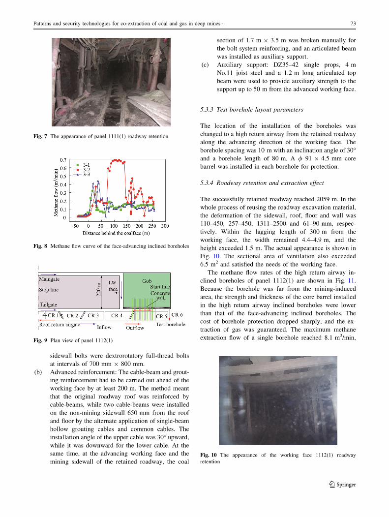
5.2.4 Effect of roadway retention and extraction
The length of successful roadway retention reached
1608 m. In the whole process of roadway excavation for its
reuse, the deformation of the sidewall, roof, floor and
backfill wall were 760, 235, 1215 and 50 mm, respectively.
When the lagging length from the working face reached
80–100 m, the roadway achieved stability. The sectional
area of the roadway was approximately 4–5 m2. The actual
appearance is shown in Fig. 7.
The methane flow rates for the face-advancing inclined
boreholes of panel 1111(1) are shown in Fig. 8. The
maximum methane flow of the extraction borehole reached
4.9 m3/min and the average methane flow reached 1.9 m3/
min. The effective extraction length was more than 150 m.
It met the needs of working face of gas extraction.
5.3 Roadway retention and the high return airway
inclined borehole
5.3.1 Engineering and geological conditions
As highlighted in Fig. 9, the average mining depth of panel
1112 (1) in the Zhuji Mine was 960 m. The mining height
was 1.8 m, the CH4 content 4.73–5.15 m3/t, the ground
temperature 36.5–45 �C, the panel length 2059 m and the
thickness of the working coal seam 1.37 m. The roof of the
seam was made up of, from the bottom up, 4.8 m thick
mudstone, a 0.2 m thick coal streak and 4.2 m thick fine
sandstone. The floor of the seam was made up of, from the
top down, 4.5 m thick mudstone, a 0.8 m thick coal seam
and 3.2 m thick mudstone.
5.3.2 Roadway retention surrounding rock control
parameters
(a) Initial support: The roadway cross section was
5 m 9 3 m. The ‘‘three highs’’ bolt and cable-beam
were used for the active support. The roof bolts were
sinistral non-longitudinal-rib high strength bolts. The
Fig. 6 Plan view of panel 1111(1)
72 N. Zhang et al.
123
sidewall bolts were dextrorotatory full-thread bolts
at intervals of 700 mm 9 800 mm.
(b) Advanced reinforcement: The cable-beam and grout-
ing reinforcement had to be carried out ahead of the
working face by at least 200 m. The method meant
that the original roadway roof was reinforced by
cable-beams, while two cable-beams were installed
on the non-mining sidewall 650 mm from the roof
and floor by the alternate application of single-beam
hollow grouting cables and common cables. The
installation angle of the upper cable was 30� upward,while it was downward for the lower cable. At the
same time, at the advancing working face and the
mining sidewall of the retained roadway, the coal
section of 1.7 m 9 3.5 m was broken manually for
the bolt system reinforcing, and an articulated beam
was installed as auxiliary support.
(c) Auxiliary support: DZ35–42 single props, 4 m
No.11 joist steel and a 1.2 m long articulated top
beam were used to provide auxiliary strength to the
support up to 50 m from the advanced working face.
5.3.3 Test borehole layout parameters
The location of the installation of the boreholes was
changed to a high return airway from the retained roadway
along the advancing direction of the working face. The
borehole spacing was 10 m with an inclination angle of 30�and a borehole length of 80 m. A / 91 9 4.5 mm core
barrel was installed in each borehole for protection.
5.3.4 Roadway retention and extraction effect
The successfully retained roadway reached 2059 m. In the
whole process of reusing the roadway excavation material,
the deformation of the sidewall, roof, floor and wall was
110–450, 257–450, 1311–2500 and 61–90 mm, respec-
tively. Within the lagging length of 300 m from the
working face, the width remained 4.4–4.9 m, and the
height exceeded 1.5 m. The actual appearance is shown in
Fig. 10. The sectional area of ventilation also exceeded
6.5 m2 and satisfied the needs of the working face.
The methane flow rates of the high return airway in-
clined boreholes of panel 1112(1) are shown in Fig. 11.
Because the borehole was far from the mining-induced
area, the strength and thickness of the core barrel installed
in the high return airway inclined boreholes were lower
than that of the face-advancing inclined boreholes. The
cost of borehole protection dropped sharply, and the ex-
traction of gas was guaranteed. The maximum methane
extraction flow of a single borehole reached 8.1 m3/min,
Fig. 7 The appearance of panel 1111(1) roadway retention
Fig. 8 Methane flow curve of the face-advancing inclined boreholes
Fig. 9 Plan view of panel 1112(1)
Fig. 10 The appearance of the working face 1112(1) roadway
retention
Patterns and security technologies for co-extraction of coal and gas in deep mines��� 73
123

and the effective extraction reached more than 100 m. The
required volumes of working face gas extraction were met.
6 Conclusions
(1) Three measures for the co-extraction of coal and gas
without an entry pillar (CECGWEP) were intro-
duced. They were roadway retention and face-lag-
ging inclined boreholes, roadway retention and face-
advancing inclined boreholes, and roadway retention
and high return airway inclined boreholes.
(2) Several essential techniques were put forward to
improve the maintenance effects for retained entry-
ways and to stabilize the boreholes which provide
pressure relief in the strata. These used presplitting
blasts, divisional control technology on surrounding
rock in the retained entryways, ‘‘the trinity’’ sur-
rounding rock controlling technique in retained
entryways, regional control technology of borehole
maintenance and rapid casing installation and bore-
hole sealing technology.
(3) The faces 1111(1) and 11112(1) in the Zhuji Mine
were considered for the latter two measures. Ac-
cording to the results, the CECGWEP technology
can effectively solve the problems in deep mines.
The maximum gas drainage flow of a single hole can
reach 8.1 m3/min, and the effective drainage dis-
tance can be extended up to 150 m or more.
Acknowledgments The research was supported by Program for
Changjiang Scholars and Innovative Research Team in University
(IRT_14R55), and the National Natural Science Foundation of China
under Grant No. NSFC-51274193.
Open Access This article is distributed under the terms of the
Creative Commons Attribution 4.0 International License (http://
creativecommons.org/licenses/by/4.0/), which permits unrestricted
use, distribution, and reproduction in any medium, provided you give
appropriate credit to the original author(s) and the source, provide a
link to the Creative Commons license, and indicate if changes were
made.
References
Bibler CJ, Marshall JS, Pilcher RC (1998) Status of worldwide coal
mine methane emissions and use. Int J Coal Geol 35:283–310
Kang H, Niu D, Zhang Z, Lin J, Li Z, Fan M (2010) Deformation
characteristics of surrounding rock and supporting technology of
gob-side entry retaining in deep coal mine. Chin J Rock Mech
Eng 29:1977–1987
Karacan CO, Ruiz FA, Cote M, Phipps S (2011) Coal mine methane:
a review of capture and utilization practices with benefits to
mining safety and to greenhouse gas reduction. Int J Coal Geol
86:121–156
Keim SA, Luxbacher KD, Karmis M (2011) A numerical study on
optimization of multilateral horizontal wellbore patterns for
coalbed methane production in Southern Shanxi Province,
China. Int J Coal Geol 86:306–317
Kong S, Cheng Y, Ren T, Liu H (2014) A sequential approach to
control gas for the extraction of multi-gassy coal seams from
traditional gas well drainage to mining-induced stress relief.
Appl Energy 131:67–78
Li W, Cheng Y, Guo P, An F, Chen M (2014) The evolution of
permeability and gas composition during remote protective
longwall mining and stress-relief gas drainage: a case study
of the underground Haishiwan Coal Mine. Geosci J
18:427–437
Liu C, Zhou F, Yang K, Xiao X, Liu Y (2014) Failure analysis of
borehole liners in soft coal seam for gas drainage. Eng Fail Anal
42:274–283
Lu S, Cheng Y, Ma J, Zhang Y (2014) Application of in-seam
directional drilling technology for gas drainage with benefits to
gas outburst control and greenhouse gas reductions in Daning
coal mine, China. Nat Hazards 73:1419–1437
Pan R, Cheng Y, Yuan L, Yu M, Dong J (2014) Effect of bedding
structural diversity of coal on permeability evolution and gas
disasters control with coal mining. Nat Hazards 73:531–546
Whittles DN, Lowndes IS, Kingman SW, Yates C, Jobling S (2007)
The stability of methane capture boreholes around a long wall
coal panel. Int J Coal Geol 71:313–328
Xia T, Zhou F, Liu J, Hu S, Liu Y (2014) A fully coupled coal
deformation and compositional flow model for the control of the
pre-mining coal seam gas extraction. Int J Rock Mech Min
72:138–148
Xie H, Zhou H, Xue D, Gao F (2014) Theory, technology and
engineering of simultaneous exploitation of coal and gas in
China. J China Coal Soc 39:1391–1397
Xue S, Yuan L, Wang Y, Xie J (2014) Numerical analyses of the
major parameters affecting the initiation of outbursts of coal and
gas. Rock Mech Rock Eng 47:1505–1510
Yang W, Lin B, Yan Q, Zhai C (2014) Stress redistribution of
longwall mining stope and gas control of multi-layer coal seams.
Int J Rock Mech Min 72:8–15
Yuan L (2008) The technique of coal mining and gas extraction by
roadway retaining and borehole drilling. J China Coal Soc
33:898–902
Yuan L, Xue J, Zhang N, Lu P (2013) Development orientation and
status of key technology for mine underground coal bed methane
drainage as well as coal and gas simultaneous mining. Coal Sci
Technol 9:6–11
Zhang N, Yuan L, Han C, Xue J, Kan J (2012) Stability and
deformation of surrounding rock in pillarless gob-side entry
retaining. Safety Sci 50:593–599
Fig. 11 Methane flow curve of the high return airway inclined
boreholes
74 N. Zhang et al.
123

Zhang NC, Esterle J, Zhang N et al (2013) Analysis on Wedge-shaped
roof mechanical behaviours under a thick sandstone layer with
different longwall mining speed. In: Proceedings of 3rd inter-
national workshop on mine hazards prevention and control,
Brisbane, pp 369–375
Zhang N, Zhang NC, Han C, Qian D, Xue F (2014) Borehole stress
monitoring analysis on advanced abutment pressureinduced by
Longwall Mining. Arabian J Geosci 7:457–463
Zheng X, Feng X, Zhang N, Liu J, Zhang L (2013) Fissures evolution
law and gas drainage characteristics of remote decompressed
mining. Disaster Adv 6:164–176
Zheng X, Feng X, Zhang N, Gong L, Hua J (2014) Serial decoupling
of bolts in coal mine roadway supports. Arabian J Geosci: 1–14
Zhou H, Yang Q, Cheng Y, Ge C, Chen J (2014) Methane drainage and
utilization in coal mines with strong coal and gas outburst dangers: a
case study in Lulingmine, China. J Natural Gas Sci Eng 20:357–365
Patterns and security technologies for co-extraction of coal and gas in deep mines��� 75
123


![Security Patterns[1]](https://img.pdfslide.us/doc/110x75/577cc94e1a28aba711a3b54b/security-patterns1.jpg)
