Embed Size (px)
Citation preview
VIRTUAL REALITY AND PROTOTYPING June 1999, Laval (France)
Patrice TORGUET♦, Olivier BALET♠, Enrico GOBBETTI♣,
Jean-Pierre JESSEL♦, Jérôme DUCHON♠, Eric BOUVIER♣
♦IRIT, Paul Sabatier University, 118, Route de Narbonne31062 Toulouse Cedex, France
[email protected] http://www.irit.fr/~Patrice.Torguet
♠CS-SI, 13, Rue Villet, Z.I. du Palays31029 Toulouse, France
[email protected]://www.cisi.fr/
♣CRS4, VI Strada OVESTZ.I. Macchiareddu
09010 UTA (CA - Italy)[email protected]
http://www.crs4.it/~gobbetti
����������� ��� Virtual Prototyping, Collaborative Working, Distributed Virtual Reality��� �����������
Prototype design and testing is an indispensable stage of any projectdevelopment in many fields of activity, such as aeronautical, spatial,automotive industries or architecture. Scientists and engineers rely onprototyping for a visual confirmation and validation of both their ideas andconcepts. Using computers for designing digital prototypes is not a new ideasince CAD applications are nowadays widely used. In this paper we presenthow new advances in 3D interaction and real time visualisation researchdomains lead to the development of a collaborative and really interactivesystem for virtual prototyping. This work is supported by the EuropeanCommunity through the ESPRIT programme 4.�������! "�La conception et la vérification de maquettes est une étape indispensable dansla réalisation d’un projet dans divers champs d’activité commel’aéronautique, le spatial, l’ industrie automobile ou le bâtiment. Lesscientifiques et les ingénieurs se servent du maquettage pour confirmer etvalider leurs idées et concepts. L’utilisation de systèmes informatiques pourcréer des maquettes virtuelles n’est pas une idée nouvelle puisque la CAO esttrès largement utilisée de nos jours. Ce document montre comment lesnouvelles avancées de la recherche en interaction 3D et visualisation tempsréel peuvent permettre la réalisation d’un système de maquettage virtuelcollaboratif et réellement interactif. Ces travaux sont sponsorisés par laCommunauté Européenne grâce au 4ème programme de recherche ESPRIT.
VIRTUAL REALITY AND PROTOTYPING June 1999, Laval (France)
Patrice TORGUET♦, Olivier BALET♠, Enrico GOBBETTI♣,
Jean-Pierre JESSEL♦, Jérôme DUCHON♠, Eric BOUVIER♣
♦IRIT, Paul Sabatier University, 118, Route de Narbonne31062 Toulouse Cedex, France
[email protected] http://www.irit.fr/~Patrice.Torguet
♠CS-SI, 13, Rue Villet, Z.I. du Palays31029 Toulouse, France
[email protected]://www.cisi.fr/
♣CRS4, VI Strada OVESTZ.I. Macchiareddu
09010 UTA (CA - Italy)[email protected]
http://www.crs4.it/~gobbetti
#�$ %�&�'�(�)�&
Prototype design and testing is an indispensable stage of any projectdevelopment in many fields of activity, such as aeronautical, spatial,automotive industries or architecture. Scientists and engineers rely onprototyping for a visual confirmation and validation of both their ideas andconcepts. Using computers for designing digital prototypes is not a new ideasince CAD applications are nowadays widely used. In this paper we presenthow new advances in 3D interaction and real time visualization researchdomains lead to the development of a collaborative and really interactivesystem for virtual prototyping. This work is supported by the EuropeanCommunity through out the ESPRIT programme 4.
*�+�,.-0/�1�2 354 Virtual Prototyping, Collaborative Working, Distributed Virtual Reality
687:9�; <�=�>�? @ A�<CBD>;Decisions taken during the design phase of large scale engineering projects are often the most delicateones, because of their possibly dramatic effect on final results, timings, and costs. Mock-ups areroutinely used for applications such as testing equipment integration, accessibility and spacerequirements in domains ranging from aerospace and automotive manufacturing to architecture.Virtual prototyping enables designers to test and improve their design. The process is the same aswhen using physical mock-ups but virtual prototyping is more efficient, you can use it and with moreopportunities for multi-site collaborations [1].
The visual capabilities of present CAD tools are much too limited to make interactive inspection andmodel manipulation possible. With such systems, it takes a fair amount of time and imagination toisolate design errors. Even more important, the lack of support for co-operative work makes
VIRTUAL REALITY AND PROTOTYPING June 1999, Laval (France)
information sharing among geographically remote people difficult. Thus, large engineering projectshave often been accompanied by the development of in-house virtual prototyping tools [2], showingthe need for a general-purpose collaborative virtual prototyping solution.
This document first presents the methodologies and technologies which enable collaborative virtualprototyping tools to be built. Then, CAVALCADE concepts and its architecture are described. Wethen present each software related workpackages. Finally, the conclusion deals with the actualimplementation of CAVALCADE along with future uses of the software.
EF:GIHKJ�L MN M�OPM�QRDH�SUTV N"WXH�Y�L V MODMQ�RPH�SNatural interaction with digital mock-ups is very important, especially for testing purposes: byproviding a virtual reality interface to the model, it is possible to give direct answers to importantquestions such as "can a short driver reach the controls on the dash ? Can an oil filter come straightout or does it have to be wiggled past some other components ?" [3, 4].
In an attempt to overcome present CAD system interactivity and concurrent design limitations, largeengineering projects have often been accompanied by the development of various kinds of specialisedvirtual prototyping tools [2]. Examples include the ISS VR Demonstrator used by Rolls-Royce tomake an assessment of how easy it would be to build an engine and maintain it [5] and Boeing’s high-performance engineering visualisation system used during the design of the 777 [6]. Moreover, theFrench Space Agency (CNES) and CS-SI have jointly launched the PROVIS [7, 8] research project in1995 in order to develop software solutions for satellite designers to create, manipulate, and studytheir models using digital mock-ups. Meanwhile, CRS4 and CERN have jointly developed the i3dsystem for supporting the design of CERN’s Large Hadron Collider [1, 9]. These efforts show theinterest of interactive virtual prototyping for early testing of designs.
The need for large-scale collaborative design tools has been recently recognised in the USA by theDefence Advanced Research Project Agency, which, in June 1997, announced its support for theVELA project, the latter being a proof of concept for a globally distributed design of multimediaprocessor chips [10].
Recently, research and development efforts for building virtual prototyping systems have startedindependently from the need of a specific project. Ongoing research at the Fraunhofer Centre forResearch in Computer Graphics is studying how to integrate existing tools to provide virtualprototyping capabilities to existing CAD systems [11]. Some recent CAD products add-ons such asPTC Pro/Fly-Through, Mechanical Dynamics’ ADAMS, Matra Datavision's Megavision, ProsolviaClarus Real-Time Link, and EDS Unigraphics Modelling module follow the same direction, providingreal-time visualisation capabilities for engineering designs.
Division’s dV/Mock-Up and dV/Reality and EAI’s VisMockUp are among the few products allowingdesigners to work on a shared prototype. However, their 3D interaction model does not permitaccurate and fast operations and their co-operative features are mainly limited to networked reviewsession without any telecommunication facilities. Working Model 3D, a Windows/NT product by theAmerican company Knowledge Revolution, which concentrates more on motion simulation than onreal-time interaction, has been selected by readers of NASA Tech Brief as the most significant newproduct introduced for the engineering community in 1996, thus showing the strategic importance ofvirtual prototyping software to industrial companies.
Unfortunately, most of these solutions suffer from severe drawbacks concerning either 3D interactionor collaborative capabilities. The latter issue is for sure one of the less developed in the virtualprototyping software industry although most of the recent large projects have reached a world-widedimension.
We think that it is now technologically possible to provide managers and designers with a powerfuland intuitive software solution for collaborative virtual prototyping by integrating recent advancedvisualisation techniques in several technological areas including distributed virtual reality,time-critical rendering techniques, 3D user interfaces, and projection-based visual displays.
CS-SI is currently leading the CAVACALDE Esprit project which aims at using all these techniquestogether for the development of a commercial product. This two-year-long project involves severalend-user partners coming from different industrial domains to ensure the success of the final product:ESA/ESTEC (the European Space Agency ), SEAT (the Spanish car builder), CSTB (the French
VIRTUAL REALITY AND PROTOTYPING June 1999, Laval (France)
scientific and technical centre for construction) and SNCF (the French national railway company).They provide a complete industrial setting for the specification and the tests of the product by beinggreatly involved in the project. The software application is currently being developed by CS-SI, IRITand CRS4 while AIS (an Italian software/hardware development society) will enhance a hardwaredevice for stereo viewing.
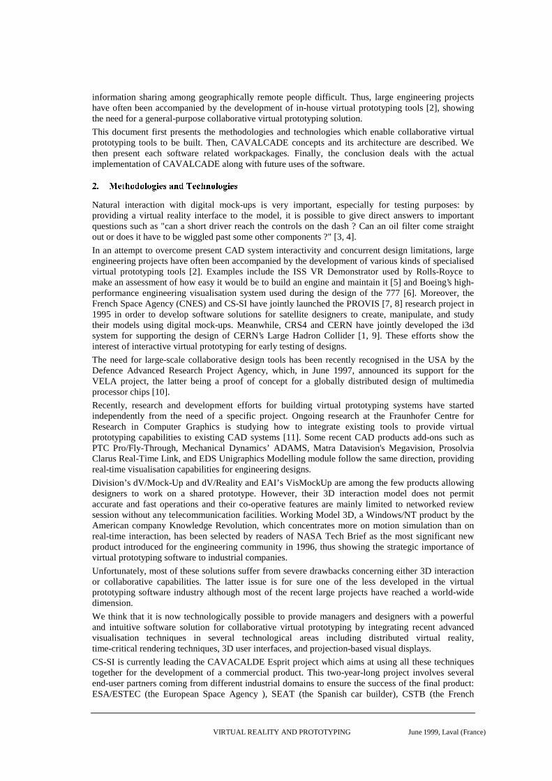
Z[:\�]�^�]�_`\�]�a�bdc�ef c�g�h i�jUkf l"mPi�jnjoep�iCqrks�gtks�c�u mDi�g�c�i�v s�gWithin CAVALCADE we use two main components in order to define a virtual environment: wyx{zD|PzD|Dw~}which encapsulate graphical objects and their behaviours; and ���D� ���K��� which are the base of interactionand information exchange between entities. Both components are brought together in a ��� ���D��K��8��� ���~���5� (Figure 1).
Virtual Universe
Stimuli
Entities
Entity
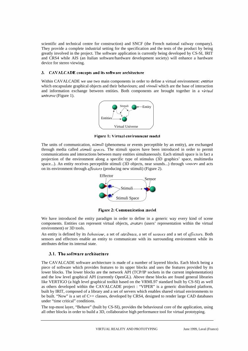
���D�� ����������D����� �¡���¢ £�D��¤�¢¦¥"��¢ �§¥¨¤© ��¡The units of communication, ª�«D¬ �®8¯~¬ (phenomena or events perceptible by an entity), are exchangedthrough media called °5±P² ³�´8µ~²¶°¸·`¹º�»~° . The stimuli spaces have been introduced in order to permitcommunications and interactions between many entities simultaneously. Each stimuli space is in fact aprojection of the environment along a specific type of stimulus (3D graphics’ space, multimediaspace...). An entity receives perceptible stimuli (3D objects, near sounds...) through ¼5½~¾�¼�¿8ÀÁ¼ and actson its environment through  ÃDÃ�Â�Ä�ÅDÆ8ÇÁÈ (producing new stimuli) (Figure 2).
Stimuli Space
Stimuli
EffectorSensor
É�ÊPË�Ì Í�ÎtÏ{Ð�Ñ�Ò�ӨӨ̦ԦÊPÕ�Ö×�ÊPÒ�Ô"Ó¨ÒØ Î�ÙWe have introduced the entity paradigm in order to define in a generic way every kind of scenecomponents. Entities can represent virtual objects, ÚKÛ�ÚÜDÚ8ÝoÞ (users’ representation within the virtualenvironment) or 3D tools.
An entity is defined by its ßàyá{âKã�äDåæ8ç , a set of è�éPé ê�ëDìí�éPîyï , a set of ð5ñ~ò�ð�ó�ô�ð and a set of õ öPö�õ�÷�øPùKú�û . Bothsensors and effectors enable an entity to communicate with its surrounding environment while itsattributes define its internal state.
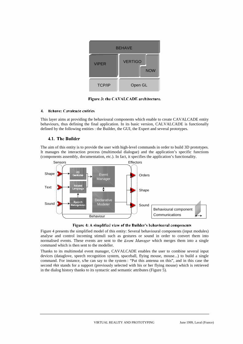
ünýDþ ý�ÿ���������� �����������������������������
The CAVALCADE software architecture is made of a number of layered blocks. Each block being apiece of software which provides features to its upper blocks and uses the features provided by itslower blocks. The lower blocks are the network API (TCP/IP sockets in the current implementation)and the low level graphical API (currently OpenGL). Above these blocks are found general librarieslike VERTIGO (a high level graphical toolkit based on the VRML97 standard built by CS-SI) as wellas others developed within the CAVALCADE project : “VIPER” is a generic distributed platform,built by IRIT, composed of a library and a set of servers which enables shared virtual environments tobe built. “Now” is a set of C++ classes, developed by CRS4, designed to render large CAD databasesunder “ time critical” conditions.
The top-most layer, “Behave” (built by CS-SI), provides the behavioural core of the application, usingall other blocks in order to build a 3D, collaborative high performance tool for virtual prototyping.
VIRTUAL REALITY AND PROTOTYPING June 1999, Laval (France)
BEHAVE
VIPER VERTIGO
NOW
TCP/IP Open GL
�����! �"�#%$'&!(*)�#,+.-./.-.01+.-.2�3546"878)9�:(*#87�(; �"�#8<
= <?>A@[email protected]�D!C6H:I�C!J�@,@8K�L*M�L;M�@8N
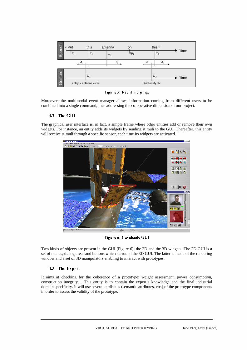
This layer aims at providing the behavioural components which enable to create CAVALCADE entitybehaviours, thus defining the final application. In its basic version, CALVALCADE is functionallydefined by the following entities : the Builder, the GUI, the Expert and several prototypes.
O�P�Q�PSR�T�U�VXW�Y[Z]\�U�^
The aim of this entity is to provide the user with high-level commands in order to build 3D prototypes.It manages the interaction process (multimodal dialogue) and the application’s specific functions(components assembly, documentation, etc.). In fact, it specifies the application’s functionality.
Effectors
Behaviour
Sensors
_a`bdc[e*f gih c;e
jlk f�gmh kanoakap q g k*q c
r�s c;c*t*uv c;t*w qxpxy f y w p
EventManager
Shape
Text
Sound
Orders
Shape
Sound
DeclarativeModeler
Behavioural component
Communications
z�{�|!}9~8�,���6���m{�������{:�*{:�����6{:�����!�'�*���,�A}�{��:����~�� ���9�8���6�!{��!}�~��!�F�8�������6�������;�
Figure 4 presents the simplified model of this entity: Several behavioural components (input modules)analyse and control incoming stimuli such as gestures or sound in order to convert them intonormalised events. These events are sent to the ����� ��¡�¢5£l��£�¤�� ¥ which merges them into a singlecommand which is then sent to the modeller.
Thanks to its multimodal event manager, CAVALCADE enables the user to combine several inputdevices (dataglove, speech recognition system, spaceball, flying mouse, mouse...) to build a singlecommand. For instance, s/he can say to the system : “Put this antenna on this” , and in this case thesecond ¦ §�¨ © stands for a support (previously selected with his or her flying mouse) which is retrievedin the dialog history thanks to its syntactic and semantic attributes (Figure 5).
VIRTUAL REALITY AND PROTOTYPING June 1999, Laval (France)
« Put this antenna on this »
entity « antenna » clic 2nd entity dic
tp1 tp2 tp4 tp5
tg2
Time
Time
tp3
Ges
ture
Spe
ech
tg1
1δ 2δ 1δ 2δ
ª�«�¬!9®8¯,°�±6²1³!¯�´�µ�¶�¯�®8¬!«�´�¬6·
Moreover, the multimodal event manager allows information coming from different users to becombined into a single command, thus addressing the co-operative dimension of our project.
¸�¹ º�¹S»�¼�½�¾�¿ÁÀ
The graphical user interface is, in fact, a simple frame where other entities add or remove their ownwidgets. For instance, an entity adds its widgets by sending stimuli to the GUI. Thereafter, this entitywill receive stimuli through a specific sensor, each time its widgets are activated.
Â�Ã�Ä!Å�Æ�Ç%È'É6Ê.Ë!Ì�Ë6Í:Î�Ë!Ï�Ç,Ð�Ñ.Ò
Two kinds of objects are present in the GUI (Figure 6): the 2D and the 3D widgets. The 2D GUI is aset of menus, dialog areas and buttons which surround the 3D GUI. The latter is made of the renderingwindow and a set of 3D manipulators enabling to interact with prototypes.
Ó�Ô Õ�ÔSÖ�×�Ø%Ù�ÚÜÛ�Ø!Ý�Þ
It aims at checking for the coherence of a prototype: weight assessment, power consumption,construction integrity… This entity is to contain the expert’s knowledge and the final industrialdomain specificity. It will use several attributes (semantic attributes, etc.) of the prototype componentsin order to assess the validity of the prototype.
VIRTUAL REALITY AND PROTOTYPING June 1999, Laval (France)
ß�à�ß�àSá�â�ã�ä�å�æ�ç�æ�ç è�ä�ã�é
The prototypes will also be modelled according to the entity model. Thus, a 3D entity will embedseveral behavioural components such as “Dynamics” to simulate forces and torque applied to theentity or “Documentation Access” to enable the user to browse associated online documentationbrowsing. The prototype stores all its documentation with an URL pointing toward a user-definedHTML page. This page contains an HTML form which permits the edition of non 3D prototypeproperties and triggers access to external technical databases thanks to SQL request and ODBC1
technology.
ê!ë?ì.ímî�ï1ð�ñ6ò.ó�ômõ*ö8ó�÷�ø�õ*ù8úüû.ý!ö�ù
VIPER [12] is used within CAVALCADE to provide the necessary distributed architecture of such acollaborative application.
It is a generic Distributed Virtual Reality system, like MASSIVE [13], DIVE [14] or VLNET [15],and has been created in order to design any kind of application.
We will describe in this part of the document the distribution of a virtual environment using VIPER.
þ�ÿ���ÿ����������� ������������������ �������
VIPER entities exist in two flavours: simple entities which are managed by the site where they havebeen created and duplicated entities which exist on a set of sites (usually all the sites which manage agiven collaborative session). Duplicated entities may define duplicated attributes which aresynchronised by VIPER on a set of sites (i.e. when such an attribute is modified on one site, all othersites copies of this attributes are updated).
��� �������� "!# %$'&�!�(�)�*+ ,!��- ")�(/.�*0 �!�1���2
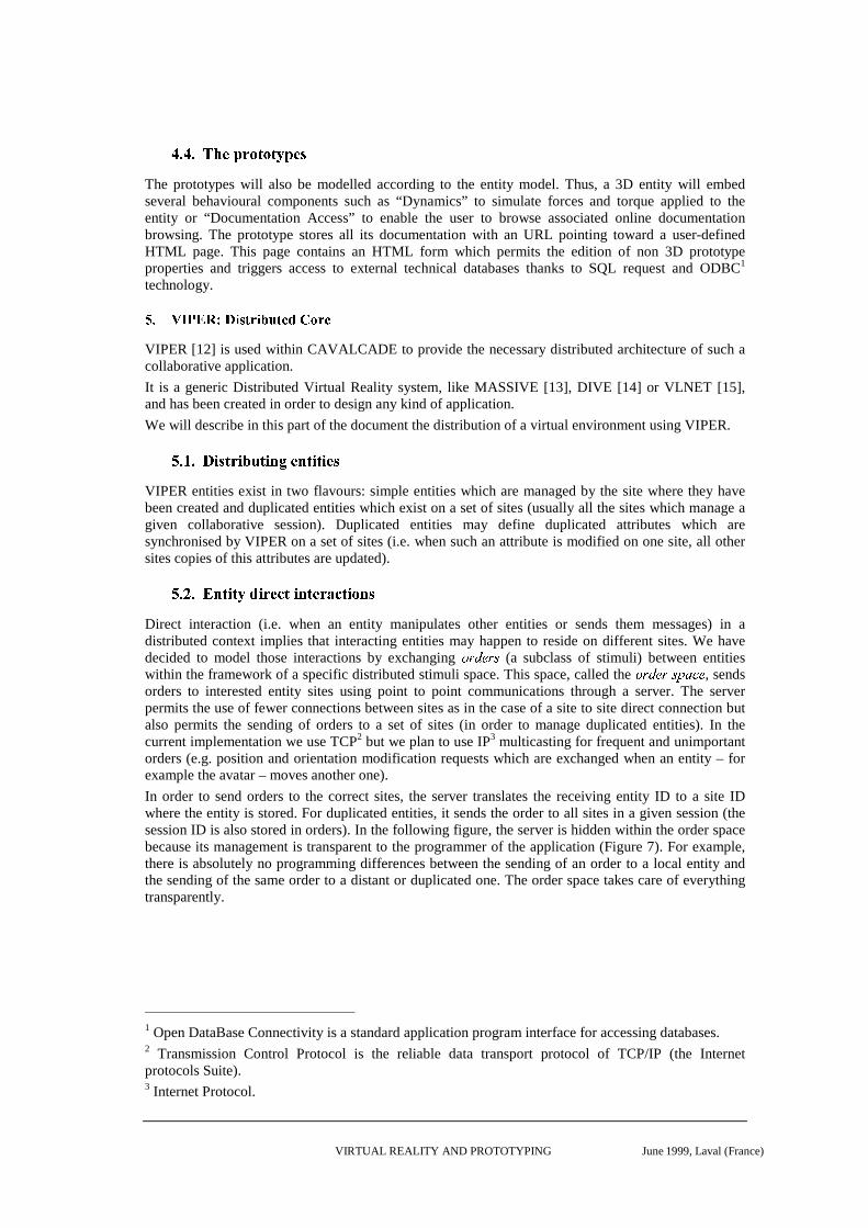
Direct interaction (i.e. when an entity manipulates other entities or sends them messages) in adistributed context implies that interacting entities may happen to reside on different sites. We havedecided to model those interactions by exchanging 354�6/784:9 (a subclass of stimuli) between entitieswithin the framework of a specific distributed stimuli space. This space, called the ;=<?>/@%<BADCFEHG�@ , sendsorders to interested entity sites using point to point communications through a server. The serverpermits the use of fewer connections between sites as in the case of a site to site direct connection butalso permits the sending of orders to a set of sites (in order to manage duplicated entities). In thecurrent implementation we use TCP2 but we plan to use IP3 multicasting for frequent and unimportantorders (e.g. position and orientation modification requests which are exchanged when an entity – forexample the avatar – moves another one).
In order to send orders to the correct sites, the server translates the receiving entity ID to a site IDwhere the entity is stored. For duplicated entities, it sends the order to all sites in a given session (thesession ID is also stored in orders). In the following figure, the server is hidden within the order spacebecause its management is transparent to the programmer of the application (Figure 7). For example,there is absolutely no programming differences between the sending of an order to a local entity andthe sending of the same order to a distant or duplicated one. The order space takes care of everythingtransparently.
1 Open DataBase Connectivity is a standard application program interface for accessing databases.2 Transmission Control Protocol is the reliable data transport protocol of TCP/IP (the Internetprotocols Suite).3 Internet Protocol.
VIRTUAL REALITY AND PROTOTYPING June 1999, Laval (France)
S4
S1
S2 S3
Order spaceOrderCoding
DecodingDecoding
I�JLKHM�N�O�PRQHSFT�O�U/N"V�O�N�WYX�ZH[�O
\�] ^�]`_,a�b�c�d5e�b�a�f/g-hji�k/k�f�l=l�h"mon�f�pqm?h�fsrutwvyx{z8|�}Df�l
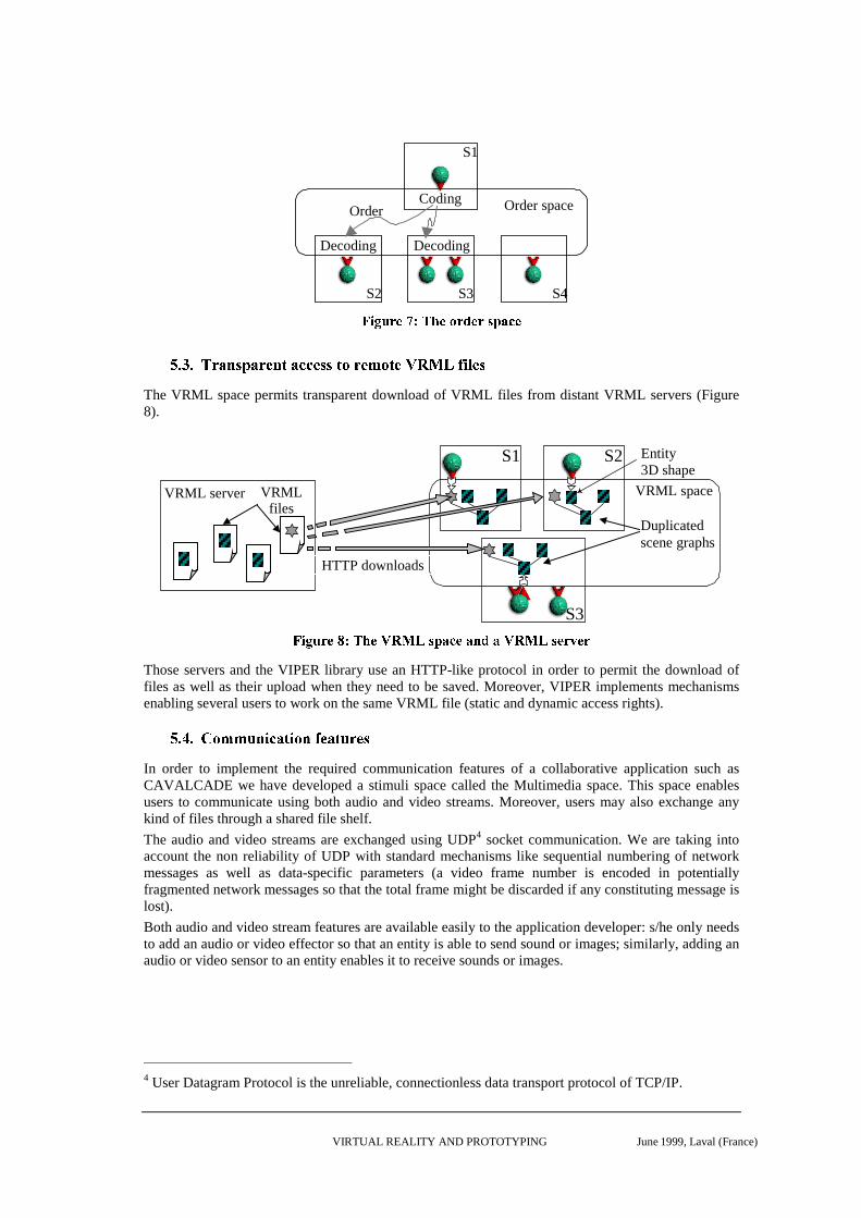
The VRML space permits transparent download of VRML files from distant VRML servers (Figure8).
S1
S3
VRML space
S2
Duplicatedscene graphs
Entity3D shape
VRML server VRMLfiles
HTTP downloads
~����/�������R�H�F�����j�j�y�q�Y���H�����/�������j���y�q�:���"�/���Those servers and the VIPER library use an HTTP-like protocol in order to permit the download offiles as well as their upload when they need to be saved. Moreover, VIPER implements mechanismsenabling several users to work on the same VRML file (static and dynamic access rights).
�������`�u���������¡ �¢/£�¤" �����¥Y¦�£�¤"��§�¦�¨
In order to implement the required communication features of a collaborative application such asCAVALCADE we have developed a stimuli space called the Multimedia space. This space enablesusers to communicate using both audio and video streams. Moreover, users may also exchange anykind of files through a shared file shelf.
The audio and video streams are exchanged using UDP4 socket communication. We are taking intoaccount the non reliability of UDP with standard mechanisms like sequential numbering of networkmessages as well as data-specific parameters (a video frame number is encoded in potentiallyfragmented network messages so that the total frame might be discarded if any constituting message islost).
Both audio and video stream features are available easily to the application developer: s/he only needsto add an audio or video effector so that an entity is able to send sound or images; similarly, adding anaudio or video sensor to an entity enables it to receive sounds or images.
4 User Datagram Protocol is the unreliable, connectionless data transport protocol of TCP/IP.
VIRTUAL REALITY AND PROTOTYPING June 1999, Laval (France)
©/ª¬«j/®�¯/°`±�²´³¶µ·³¶¸Y³�¹�º¼»j½/¾/½H¿LÀ"½/Á�Â�ô/Ä�¿L½HÄ�º/Âs»jÅjÆÇÁ�½H²È½HÉ�½/¸:Â�¸The Now package is a set of C++ interfaces designed to render large CAD databases in “ time critical”conditions. It provides automatic simplification algorithms for triangular meshes and level-of-detailmanagement tools that are built on top of an efficient multiresolution structure [16].
Ê�Ë�Ì�Ë�Í�Î0Ï�Î/ÐRÑ�ÒÔÓ�Î+Õ�Ö�×DÐ�Ø
Despite the continuous improvement in performance of CPUs and graphics’ accelerators, scenesexceeding a million of polygons cannot be handled directly at interactive speeds even on high-endmachines. The traditional approach is to pre-compute a small number of independent level-of-detail(LOD) representing each object composing the scene, and to choose at run-time the best one based ona cost/benefit analysis [17, 18]. Even if LODs introduce a significant memory overhead, they arecommonly used as they match easily with current “ time critical” hardware and software architectures.Actually, as LODs are pre-computed, the polygons can be organised in the most efficient way(triangle strips, display list), exploiting raw graphics processing speed with retained-mode graphics.Moreover, LODs can be inserted directly into a scene graph architecture with minor changes in therendering engine. Therefore, the LOD approach is particularly adapted to a system likeCAVALCADE, where the scene is modelled as a set of entities organised in a VRML scene graph.
Ù�Ú Û�Ú`ÜÞÝ�ß�à�Ý+á"â0ãqä=åDà�æ�çDåDè8å�é�ê�á"åëß�ì
Users of virtual mock-up system do not want to have to deal with time critical issues when theyconceive new prototypes. Therefore we have developed simplification algorithms to automaticallycreate various representations of the cavalcade geometric entities.
As in [19], we implement mesh simplification schemes based on iterative vertex substitution in ageneric framework of greedy algorithms for heuristic optimisation. The generic greedy algorithm isparameterised by a í/î ïRð5ñDòôó5ñ�ð/õ8ö÷ , deciding which vertex substitutions are legal, and a øHùHú û:üRý8þYþÿ û?ý��/ú���ù��Lý , which assigns priorities to all vertex substitutions in the legal candidate sets. The algorithmproceeds in a series of greedy steps until the candidate set is empty. In each step, the best vertexsubstitution is removed from the candidate set, the mesh is modified accordingly, and newsubstitutions are re-evaluated for the vertices affected by the mesh change.
��� ���� ������ ���
The simplification algorithm has been implemented and tested on both Windows NT and IRIXmachines. The results presented here have been measured on a Silicon Graphics Onyx with 2 MIPSR10000 194 MHz CPU, primary data cache size of 32 Kbytes, secondary unified instruction/datacache size of 1 Mbyte, main memory size of 1Gb. Similar results where obtained with a Pentium IIprocessor at 300Mhz with 128 Mb RAM.
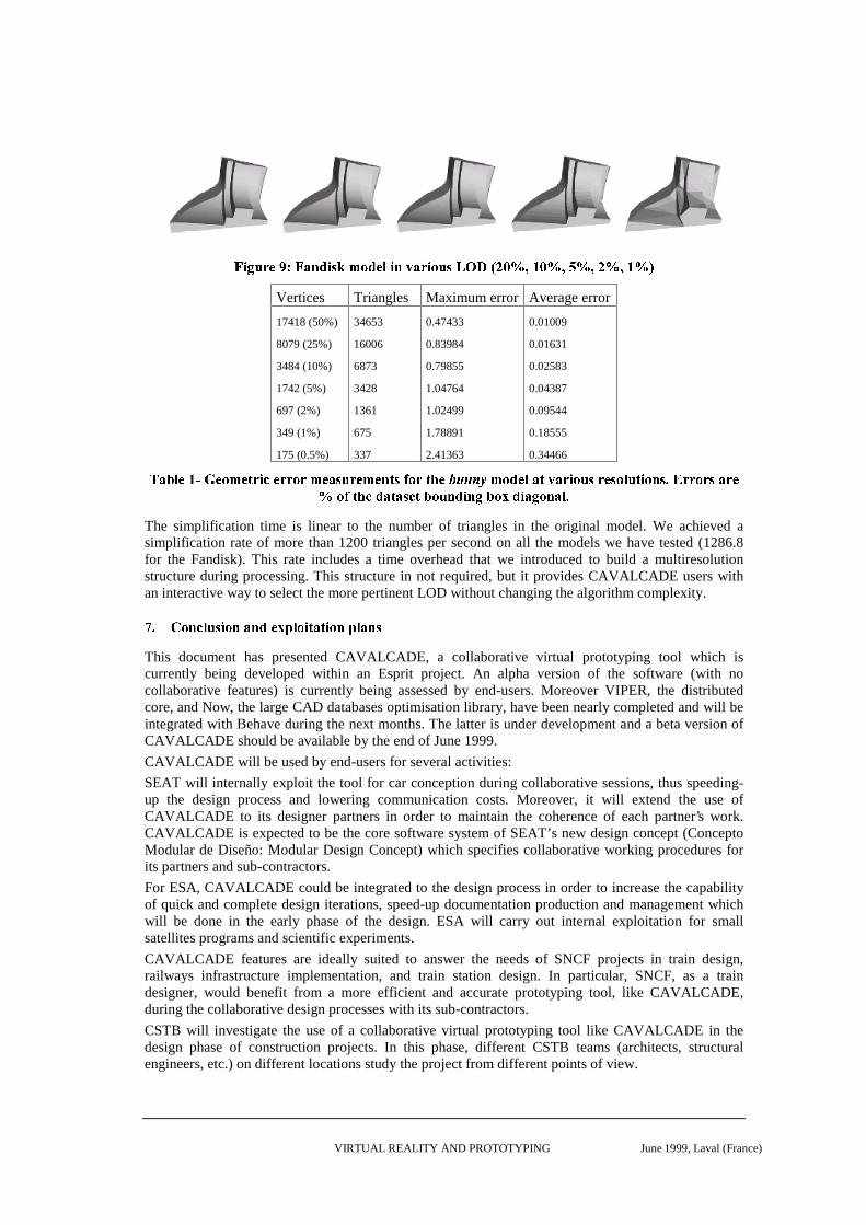
The comparison has been done using the publicly available ����� ��� tool [20], which measures surfacedeviation. Table 1 presents the results obtained on the ��� ��� ! model5. The maximum and averageerrors are similar to those obtained with more complex competing algorithms [21]. We also present inthe next figure (Figure 9) pictures of the Fandisk model6 created using our simplification algorithm inseveral levels of details (20%, 10%, 5%, 2%, 1%).
5 This model is available at the following URL: http://www-graphics.stanford.edu/data/3Dscanrep/6 This model is available at the following URL: http://www.research.microsoft.com/˜hoppe
VIRTUAL REALITY AND PROTOTYPING June 1999, Laval (France)
"�#%$�&�'�(�)+*�"-,�.�/�#�02143657/�(�89#�.6:;,�'�#�5;&�0=<?>A@CBED;FHG�IHJ F+GKI;LHG�I�D+GKI+J�G�MVertices Triangles Maximum error Average error
17418 (50%)
8079 (25%)
3484 (10%)
1742 (5%)
697 (2%)
349 (1%)
175 (0.5%)
34653
16006
6873
3428
1361
675
337
0.47433
0.83984
0.79855
1.04764
1.02499
1.78891
2.41363
0.01009
0.01631
0.02583
0.04387
0.09544
0.18555
0.34466N?O�P�Q%RAS THUVR�W7X4R�YEZ�[�\]R^Z�Z�W�Z_X6R�O�`bacZ�R�XdR�e�YE`fEW;Z�YhgcRji�k�l�lnm6o6p7qcr^s7t�uHv;t;w^x%p�y�z=w�r�zbp;s�y�uEx%p�{�z2|�}?w�w�p�w�z=t;w^r
~ p;�Huh�cr]q�t�uht�z2r^u+�cp;y�{�qcx%{�����p���q�x�t;��p;{�t�s%|The simplification time is linear to the number of triangles in the original model. We achieved asimplification rate of more than 1200 triangles per second on all the models we have tested (1286.8for the Fandisk). This rate includes a time overhead that we introduced to build a multiresolutionstructure during processing. This structure in not required, but it provides CAVALCADE users withan interactive way to select the more pertinent LOD without changing the algorithm complexity.
�;�����;���^�%�c�2���;�6���c�d�������%���%�E�;�E�%���6�����;�c�This document has presented CAVALCADE, a collaborative virtual prototyping tool which iscurrently being developed within an Esprit project. An alpha version of the software (with nocollaborative features) is currently being assessed by end-users. Moreover VIPER, the distributedcore, and Now, the large CAD databases optimisation library, have been nearly completed and will beintegrated with Behave during the next months. The latter is under development and a beta version ofCAVALCADE should be available by the end of June 1999.
CAVALCADE will be used by end-users for several activities:
SEAT will internally exploit the tool for car conception during collaborative sessions, thus speeding-up the design process and lowering communication costs. Moreover, it will extend the use ofCAVALCADE to its designer partners in order to maintain the coherence of each partner’s work.CAVALCADE is expected to be the core software system of SEAT’s new design concept (ConceptoModular de Diseño: Modular Design Concept) which specifies collaborative working procedures forits partners and sub-contractors.
For ESA, CAVALCADE could be integrated to the design process in order to increase the capabilityof quick and complete design iterations, speed-up documentation production and management whichwill be done in the early phase of the design. ESA will carry out internal exploitation for smallsatellites programs and scientific experiments.
CAVALCADE features are ideally suited to answer the needs of SNCF projects in train design,railways infrastructure implementation, and train station design. In particular, SNCF, as a traindesigner, would benefit from a more efficient and accurate prototyping tool, like CAVALCADE,during the collaborative design processes with its sub-contractors.
CSTB will investigate the use of a collaborative virtual prototyping tool like CAVALCADE in thedesign phase of construction projects. In this phase, different CSTB teams (architects, structuralengineers, etc.) on different locations study the project from different points of view.
VIRTUAL REALITY AND PROTOTYPING June 1999, Laval (France)
�;�����^���c ;¡£¢�¤�¥�¦�¤^§d¤^�c¨h©The CAVALCADE project is supported by the European Community through the ESPRITprogramme 4 (project number 26285).
ª;«�¬��®E�¯^�°�±^�²[1] Balaguer J.F. ³^´-µ·¶6¸7¹ º»¶�¼4½¿¾�À;Á+ À+Ã^Ãĺn À�Á . Proceedings Eurographics Workshop on VirtualEnvironments, 1996.
[2] Ellis G., ÅnÆHÇ�È]É ÊnÇ-Ë�Ì�Í�Î�Ï�Ð7Ñ Ò;ÓÔÉ Õ�Ö¿×Ñ Ð7Ç_ÅnÆHÇ�È�Ø=Ù�Ç^Ú�ÅcÌ;ÛÝÜ9Ñ Ê�Í�Þ;Ï�ß�à]Ç�Ï�ßáÑ�Í È»âHÏ ã7ÇäÙ£Å�Ñ Ö6Ç_Ï�Ò+ÚÝÎåÌ�Ò+ÇæÈçÑ ÒÎ�Ï Ò+Þ%è�Ï�é�Í�Þ ÊnÑ Ò�Ó·ÏêÒHÚìë?Ì�Ò;ÙnÍ ÊnÞ;é�Í�Ñ�Ì Ò , Iris Universe, Summer 1996.
[3] Potter C. D. í6î ïHî%ð�ñ òìóåô�õÄö^÷ùøEúüû�ô;ô�ò%ýVþAÿ�ÿ��9ñ�òáø��åð%ôdþ�ý2ý������ òÄî�äý . Computer Graphics World,November 1996.
[4] Balet O., ��� ��������������������������� �! "����#�$�� ��%�&'�����#(��#)�+*� �$�� ,�#(�-"./#0�� �����&'��� �1 32!� ���%����546��������� 7'8� �$ ,proceedings of Information Society Technologies conference, Vienna, 1998.
[5] Greenfield D., 9!: ;�<�=�>�?1@A;�B�<�B�< C'DE: F�GH>�<'IJB�?�?KML/INBOCQPSR�T Cambridge, Mass., MIT Press, 1996.
[6] Mc Neely W. UNV�W'X Y�ZE[ \E]�X Z�^�_NW�` a�V�`cb�d�Y)e'WgfhX \�i�d�j�X k�d�l�X�V�Ynm0Va�l o�d�`�W'p�q6j r6s�^�`�i , CERN ComputingSeminar, June 1996.
[7] Balet O., Luga H., Duthen Y., Caubet R., t6uJv�wSx/y{zh|}t6~O��� �����c���1����w!� ��������~�tA��������� �'�E� �������0�� ��� �0�����0���0�S�N������� �c� Proceedings IEEE Computer Animation, June 1997.
[8] Torguet P., Balet O., Caubet R., ���0���� ���������J�� �¡)¢���' S�£����¤�����¦¥���§§���¨���������¢ ©!�«ª!¢ ����£���§¬ �������� S®�¢ ¯�° , ±�²�³+´Nµ·¶�¸!¹N´Aº·»¼±0½¿¾ À)Á , Vilamoura, Algarve, Portugal, December 1997.
[9] Gobbetti E., Balaguer, J. F., Â�Ã�Ä�ÅÇÆNÈÉÂ/È0Ê�Ë�Ì�Í�Î'Ê�Ï Ð!Ë(Ñ�Ò!Ó�Ê�Ë�ÔÖÕ�×�ÌÙØ6Ú�Û)ÜO×�Ì�Ï È�Ý}ÆNÈÞÈ)×�Ê�Í�Ê�Ë'ßÉÃ�ÄØ6È�Ð!Ï Ì�×�È�Ô�Ë�È0Ê Ócà Reprinted in Scateni R (Ed) Scientific Visualization’95, Symposium Proceedings,World Scientific, 1995.
[10] Goering R., Clarke P. áãâSä�åçæNè�é�â'êìë�â�é�í î�ïñð�ò�í é�ó éõô�â�öø÷)è�í ù , EETimes, 16 June 1996.
[11] Jasnoch U., Klement E., Kress H., Schiffner N., ú�û�ü�ý�þ�ÿ�� � û�����ý���û�þ�ý�� �� ��� þ�����ý����6þ�û�û� ���� ���� �ý���û�þ��Oÿ! øý�þ�"� #� , Proceedings FAIM, Atlanta, 1996.
[12] Torguet P., Rubio F., Gaildrat V., Caubet R. $&%�')(�* +�%�,�-/.0* 1�(�-).�2�3�(�*�4�1,0* 15( 67-83�4�1�(�-)9:(;4�<3#4�1�3#%�.=.�-)1�(?>:* .�(�%2�'A@B4�.=')CEDF4C�-/'G* 1�H , I:J KML�N�O�PAQSR�T:J K�U�R�VFW/R�L X&O�R�YEZ�[�J�W/R�L�J \�J�[]I�J X�N�O�P)J ^MO�L�J�U�R�_ `ba , SpringerComputer Science, pages 121-136, 1996.
[13] Greenhalgh, C.M., cedBf�gMh)i7h)jkjEl&f�i7f�m7h)nFh)i7oqp iro s�htlqceuvu�w�x�yzu�{�jMo�h)nAj , Distributed SystemsEngineering, Vol. 5, No 3, September 1998, pp. 129-137, IOP Publishing.
[14] Hagsand O., Lea R., Stenius M., |?}�~ ����}������~��������#�/����~ �b��)}����������)�M����}����F�/}=}M����������}=}M~ ���]~ �����~ }M� �M~������������� , VRML’97, Monterey, CA, Feb, 1997.
[15] Pandzic I., Capin T., Lee E., Magnenat Thalmann N., Thalmann D., �����)�)�:�����G�q���M�/ ���¡����#¡�¢�������£��¤ � �M¡�¢����;¥F¢�¦F��§�¨r� §ª©B��¡ «B£��=¬:�#ª®�£����)���£�����¡�� ¯:� ¤ � �M¡�¢����;°±§¯�� �M£�§�¦F�)§7¡ ¨ , Eurographics’97, Budapest,Hungary, 1997.
[16] Bouvier E., Gobbetti E., ²´³Fµ�¶G·�¸ ¹�º)»�¼�¶)µ�·�¸�¼�½¾· ¹�¸�¿�½�À¶GºÁ³Fº/»=ÂûM· ¹Mµ�Ä�·�µ�¹MºÆż�¹Ç·�¸ ³Fº/ÈÉÄ/¹M¸�·�¸�Ä#¿�¶¿ËÊÊ�¶)¸�Ä�¿�·�¸�¼�½�» . Technical report, Cavalcade, CA-NO-NT-CR-002, February 1999.
[17] Funkhouser T. A., Sequin C. H., ÌÎÍÏËÐ�Ñ�Ò Ó�Ô�ÍÒ ÕÖÐ�×)ÏËØ�Ï�×�Ù�Ú�ÛMÒ�Ñ ÜÝtÞÚ�ÛqÒ ß7Ñ�Ô/ÛMÏà#Ñ�Ò Ó:ÔvÞ�Û�Ï�ÝFÔáÛMÏ�Ñ�Ô)ÕÎÍ�â�ÛMÒ ß�ÙÓ�Ò ÕMâÏ�×)Ò ã�Ï�Ñ�Ò�Ú�ß�Ú�Þäà�Ú�Ý?Ð7×GÔ/åeÓ:Ò Û�Ñ�âÏ�×±Ô)ßÓ�Ò ÛMÚ�ßÝFÔGß�Ñ Õ . æAçvè�é�êìëËí�îAïðî#ñ�é�òìóõô�öA÷�øùÉúAú?û:üþý±ÿ�� ��� ý������ , 1993.
[18] John Rohlf and James Helman. ������������� ������������� �"!�# $%!&���'� �%� ����( )+*,�-��. /102# �����%*,�'343�# )$502���/26�#207��������8(�/29+:;# ���&< =>$�?(@��!+#2*'3 . Computer Graphics ACBD�EFEHGJI&KML�N OPQKMR?ST'U V , pages 381–395. ACM Press, July1994.
[19] Kobbelt L., Campagna S., Seidel H. P., WYX�Z'[�Z'\�] ^�_,\�] `�Z'acb�\4d-_�b�\e`�Z�f�gih%Z,j,k `�]l2k2b�[ , mHn?o@p�q+r2s'tu�v�wyx n z�os xM{ n?|s�}+~�m u@�@�+�@� , pages 43–50, San Francisco, June18–20 1998. Morgan Kaufmann Publishers.
[20] C. Rocchini P. Cignoni and R. Scopigno. Metro: measuring error on simplified surfaces.Technical report B4-01-01-96, Institute I.E.I.-C.N.R., Pisa, Italy, Jan. 1996.http://miles.cnuce.cnr.it/cg/metro.img.html.
[21] Cignoni P., Montani C., Scopigno R., ���,� �H��� ��� �������y�����'�4����� �H�+�'� ���2�,��2�2�������2�+� ���2� �%�F� .�����H����2�' �¡F¢�£�¤¦¥H ?¢@��§+¨2©'¡, 22(1), pages 37–54, January 1998.