Embed Size (px)
Citation preview

Patio Heater User Manual
MODEL#PG139HC
Before returning to your retailer, call our customer service department at 1-888-376-9601.
DANGER:
If you smell gas: 1. Shut off gas to the appliance. 2. Extinguish any open flame. 3. If odor continues, keep away from the
appliance and immediately call your gas supplier or fire department.
WARNING:
Do not store or use gasoline or other flammable vapors and liquids in the vicinity of this or any other appliance. An LP-cylinder not connected for use shall not be stored in the vicinity of this or any other appliance.
WARNING: For outdoor use only.
OFF
PILOTLOW
HIGH
Igniterpush
WARNING: Improper installation, adjustment, alteration, service or maintenance can cause property damage, injury or death. Read the installation, operating and maintenance instructions thoroughly before installing or servicing this equipment.

2
TABLE OF CONCENTS . Product Specifications…………………………………………………………...2 Safety Information………………………………………………………………..3-5 Package Contents………………………………………………………………..6 Hardware Contents………………………………………………………….…...7 Preparation…………………………………………………………………..........7 Assembly Instructions………………………………………………………........7-14 Installing an LP Gas Tank………… ……………………………………….….. .14-15 Safety Check………………………………………………………………….… .15 Lighting Instructions………………………………………………………….…..16 Care and Maintenance ………………………………………………………….17 Troubleshooting…………………………………………………………………..18 Warranty…………………………………………………………………………..18
PRODUCT SPECIFICATIONS
Product Specifications Certification CSA Height Overall 86.60 inches Reflector Diameter 31.50 inches Rated Heat Input 40,000 BTU/HR Fuel Propane-LP Gas Supply 20-Lb LP-Gas cylinder Manifold Pressure 11 inches W.C Injector Size (diameter) 1.92 mm Safety Features Thermocouple & Tilt Switch Gas Supply Pressure Max 150 PSI, Min 5 PSI

3
SAFETY INFORMATION
Please read and understand this entire manual before attempting to assemble, operate or install the product. If you have any questions regarding the product, please call customer service at: 1-888-376-9601 from 8:00 am to 5:00 pm Eastern time , Monday to Friday. 1. The installation must conform with local codes or, in the absence of local codes,
with the National Fuel Gas Code, ANSI Z223.1 /NFPA 54, Natural Gas and Propane Installation Code, CSA B149.1, or Propane Storage and Handling Code, B149.2.
2. Minimum clearance to the combustible materials is 3.61 ft (1100mm). 3. Perform a leak test with a soapy solution:
(a) To check gas connections. (b) After connecting a new cylinder. (c) Upon re-assembly after disassembly. Please refer to the leak test procedure indicated in this instruction manual on page 15. Replace the hose assembly prior to the appliance being put into operation if there is evidence of excessive abrasion or wear, or if the hose is damaged. The pressure regulator and hose assembly supplied with the appliance must be used .The replacement hose assembly/ regulator shall be that specified by the manufacturer.
4. If you don’t feel the heater is on a stable surface, use a ground screw to fix the base of the heater on the surface where the heater is installed. Fix the base on an incline no wider than 15 degrees.
5. Place the propane hose with regulator assembly out of pathways where people may trip over it or in areas where the hose will not be subjected to accidental damage.
6. This heater is equipped with a battery-operated ignition device; please refer to the assembly instructions on page 9.
7. Materials or items when stored under the heater will be subjected to intense heat and could be seriously damaged.
8. Clothing or other flammable materials should not be hung on the heater, or placed on, under or near the heater .
9. Children and adults should be alerted to the hazards of high surface temperatures and should stay away to avoid burns or clothing ignition.
10. Young children should be carefully supervised when they are in the area of the heater.
11. Any guard or other protective device removed for servicing the heater must be replaced prior to operating the heater.
12. Installation and repair should be done by qualified service person, the heater should be inspected before use and at least annually by a qualified service person.
13. More frequent cleaning may be required as necessary. It is imperative that the control compartment, burners and circulating air passageways of the heater be kept clean.

4
SAFETY INFORMATION
14. Keep the appliance area clear and free from combustible materials, gasoline and other flammable vapors and liquids.
15. Do not obstruct the flow of combustion and ventilation air. 16. Keep the ventilation opening(s) of the cylinder enclosure free and clear from
debris. Use this appliance in a well-ventilated space only. Do not use it in a building, garage, or any other enclosed area. Use this appliance in outdoor areas described below: (a) With walls on all sides, but at least one permanent opening at ground level and no overhead cover. (b) Within a partial enclosure that includes overhead cover and no more than two
walls. These walls may be parallel, or at right angles to each other. (c) Within a partial enclosure that includes overhead cover and no more than two
walls. The following shall apply: (i) One wall that is equivalent to at least 25% of the total wall area is
completely open. (ii) 30% or more in total of the remaining wall area is open and
unrestricted. 17. The LP-gas supply cylinder to be used must be:
(a) Constructed and marked in accordance with the Specifications for LP-gas cylinders of the U.S. Department of Transportation of Dangerous Goods and Commission, CAN/CSA-B339, as applicable;
(b) Provided with a listed overfilling prevention device; and (c) Provided with a cylinder connection device compatible with the connection for
the appliance. 18. Disconnect the cylinder when the appliance is not in use. 19. Storage of an appliance indoors is permissible only if the cylinder is disconnected
and removed from the appliance. 20. Store the cylinder outdoors in a well-ventilated area (not in a building, garage, or
other enclosed area) out of the reach of children. 21. The cylinder used must include a collar to protect the cylinder valve. 22. Do not store a spare LP-gas cylinder under or near this appliance; 23. Never fill the cylinder beyond 80 percent full; 24. Place the dust cap tightly on the cylinder valve outlet whenever the cylinder is not
in use. Install only the type of dust cap on the cylinder valve that is provided with the cylinder valve. Other types of caps or plugs may result in a propane leak.
25. Inspect the visible portion of the hose before each use of the appliance. 26. More frequent cleaning may be required as necessary. It is imperative that the

5
control compartment, burners and circulating air passageways of the heater be kept
clean. 27. Every part of the heater shall be secure against displacement and shall be
constructed to maintain a fixed relationship between essential parts under normal and reasonable conditions of handling and usage. Parts not permanently secured shall be designed so they cannot be incorrectly assembled and cannot be improperly located or misaligned in removing or replacing during cleaning or other servicing.
28. CALIFORNIA PROPOSITION 65 WARNING: The burning of gas cooking fuel generates some byproducts which are on the list of substances known by the State of California to cause cancer, reproductive harm, or other birth defects. To reduce exposure to these substances, always operate this unit according to the use and care manual, ensuring you provide good ventilation when cooking with gas.

6
PACKAGE CONTENTS
T
S
J
AB
C
Q
GDF
E
L
K
N
O
I
R
H
P
M
Part Description Quantity Part Description Quantity
A Top Dome 1 K Cylinder Restraint Chain
1
B KD Dome 4 L Front Shrould (Cylinder door)
1
C Burner Assembly 1 M Base 1 D Post 1 N Caster 2 E Platform 1 O Latch 2 F Cylinder Cover 1 P Control Knob 1 G Tabletop 1 Q Upper Post Assembly
(Pre-assembled) 1
H Tabletop Support Assembly
1 R Heat Insulation Plate 1
I Back Shroud 1 S Cylinder Strip 1 J Regulator & Hose
Assembly 1 T Ring 1
7
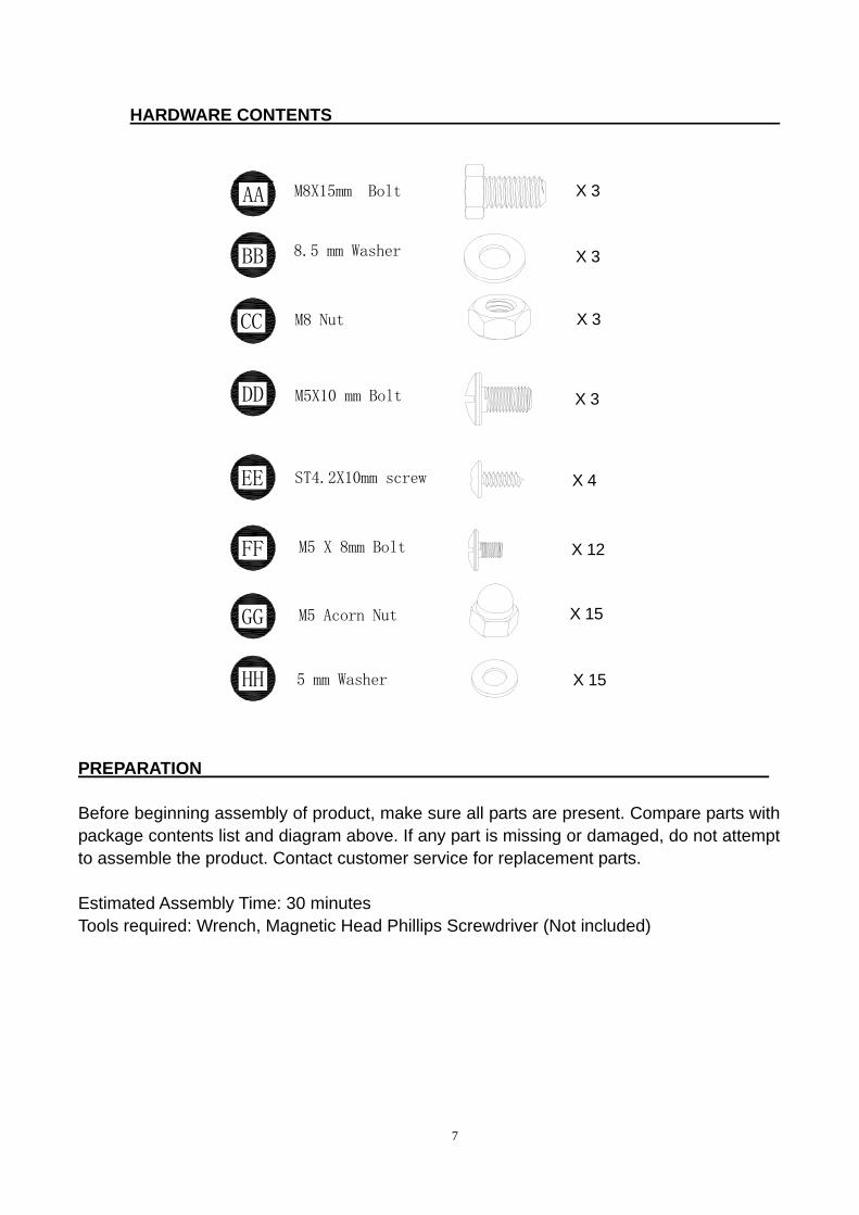
HARDWARE CONTENTS
PREPARATION
Before beginning assembly of product, make sure all parts are present. Compare parts with package contents list and diagram above. If any part is missing or damaged, do not attempt to assemble the product. Contact customer service for replacement parts.
Estimated Assembly Time: 30 minutes Tools required: Wrench, Magnetic Head Phillips Screwdriver (Not included)
HH
GG
FF
EE
DD X 3
X 3
X 3
X 3
X 12M5 X 8mm Bolt
X 155 mm Washer
M8 Nut
8.5 mm Washer
M8X15mm Bolt
CC
BB
AA
M5 Acorn Nut X 15
M5X10 mm Bolt
X 4ST4.2X10mm screw

8
ASSEMBLY INSTRUCTIONS Fig. 1
Fig. 2
1. Take the product out of package, disassemble Cylinder Cover (F) by loosening three M6 Bolts. (Fig. 1)
2. Attach Post (D) to Platform (E) with three Bolts (AA), three Washers (BB) and three Nuts (CC) (Fig. 2)
AA
BB
CC
M8X15mm Bolt
8.5 mm Washer
M8 Nut
X 3
X 3
X 3
F
M6 Bolt
CC
BB
E
AA
D

9
Fig. 3
Fig. 4
3. Connect Cylinder Cover (F) to assembled Back Shroud (I) by using three Bolts (Fig. 3), and place the Ring (T) on the Post (D)
4. Fix Tabletop Support (H) to Tabletop (G) by using four screws (EE). (Fig. 4)
EE ST4.2X10mm Screw X 4
G
H
EE
D
T
X 3Bolt M6X10
I
M6X10. Bolt
F

10
Fig. 5
Fig. 6
5. Disassemble the M5 x 10 mm Bolt from the Post (D). Put the assembled tabletop (G)+(H) to Post (D). Don’t reassemble the M5 x 10 mm Bolt to the Post (D) until Step 6 is complete.
Notes: When the Tabletop (G) is well attached, follow the steps below to adjust the height: a. Adjust the grip until it is vertical to the
post. b. Adjust the height of the tabletop to
desired position. c. Fix the position of the tabletop by
turning the grip clockwise. d. Turn until the grip is fixed. e. Clasp the chain to further fix the grip
6. Feed the valve and gas line and connect the Burner Assembly (C) to Post (D). 6.1: Feed the valve and gas line into
and through the Post (D). 6.2: Screw Burner Assembly (C) onto
Post (D) until the hole on the Upper Post Assembly (Q) is aligned with the holes on top of post (D). Fix by using one M5 ×10 mm Bolt (DD.). Ensure they are fully tightened.
6.3: Reassemble the M5 x 10 mm Bolt to Post (D) in order to limit the height of the tabletop (G). Refer to Fig. 5 & Fig. 6
Notes: a. Open the igniter cap by unscrewing the cap
counterclockwise b. Take out the battery included in the
pack of Instruction manual. c. Insert the battery to the igniter.
M5 X 10 mm Bolt
Battery
Ignitor
C
Q
DD
D
DDX 3M5X10 mm Bolt
+-
M5 X 10 mm Bolt
DGH

11
Fig. 7
Fig. 8
7. Assemble the four KD Domes (B) with four M5 × 6 mm Bolts (FF.), four M5 Acorn Nuts (GG.) and four 5 mm Washers (HH). Attach Top Dome (A) to assembled KD Domes by using eight M5 × 8 mm Bolts (FF.), eight M5 Acorn Nuts (GG.) and eight 5 mm Washers (HH) (Fig. 7)
8. Attach heat insulation plate (R) onto the bracket of the Burner Assembly (C); then attach the Assembled KD Domes (B) with Top Dome (A) to Burner Assembly (C) by using three M5 Acorn Nuts (GG) and three 5 mm Washers (HH). (Fig. 8) C
R
BA
HHGG
X 12M5 Acorn NutGG
5 mm WasherHH X 12
FF M5 X 8 mm Bolt X 12
FFHH
B
AHHGG
FF
GG
HH 5 mm Washer
GG M5 Acorn Nut
X 3
X 3

12
Fig. 9 Fig. 10
9. Insert the cylinder strip (S) into the holes of bracket on the shroud sides, making the strip parallel to the Base, in order to prevent storing the gas cylinder more than 20 lb.
10. Put the gas cylinder into the shroud. Keep the cylinder vertically upright on the base for vapor withdraws.
S

13
Fig. 11
Fig. 12
11. Connect Regulator & Hose Assembly (J) to cylinder (not included). (Fig. 11) Note: Check for leaks after connecting the gas cylinder prior to each use according to the “Checking for Leaks” section on page 14.
12. Attach Cylinder Restraint Chain (K) to fix the cylinder. (Fig. 12) and close the door after assembly.
K

14
Fig. 13
Installing LP Gas Tank Installing LP Gas Tank
13. If the heater is installed on a surface with a gradient more than 15°, fix the base to the surface by using two ground screws through the two holes on base as indicated. (Fig. 13)
1. Specific size and capacity for gas tank: To operate you will need precision-filled standard cylinder with specific size and capacity as shown.
9 KGS
20 lb
12.2 in / 31 cm
17.9 in / 45.5 cm
2. Connect 20 lb. LP Gas Tank Before connecting, be sure that there is no debris caught in the head of the LP gas tank head of the regulator valve or in the head of the burner and burner ports. Line up threads on fitting with those on regulator and rotate clockwise until tight. HAND TIGHTENS ONLY. DO NOT USE ANY HAND TOOLS TO MAKE THIS CONNECTION. Be careful not to cross threads when screwing in FITTING

15
.
SAFETY CHECK
Fig.14
Fig.15
Checking for Leaks Your patio heater has been checked at all factory connections for leakage. To check the connection at the gas hose/regulator/cylinder: a. Make leakage solution by mixing 1 part
liquid dish soap and 3 part water. b. Spoon or brush several drops (or use a
squirt bottle) of the solution onto the gas hose/regulator, regulator/cylinder and hose connection.
c. Turn on gas cylinder valve. Inspect the connections and look for bubbles.
d. If no bubbles appear, the connection is safe.e. If bubbles appear, there is leakage. Loosen
and re-tighten this connection. If it still leaks, please call customer service at: 1-888-376-9601.
3. Disconnect 20 lb. LP Gas Tank Before disconnecting make sure the LP gas tank valve is “OFF”. Disconnect gas line to tank by turning knob counterclockwise until it is loose. Store the LP gas tank in a proper location
.

16
Fig.15
Fig.16
Fig.16
Lighting Instruction 1. Turn the LP gas tank valve OFF. Push control knob in, turn
OFF, and wait 5 minutes for any gas to clear. 2. Turn the tank valve ON. Push control knob in and rotate to
PILOT. Then push the igniter button until the burner is ignited. If the burner fails to remain lit or becomes extinguished, turn the burner completely off for 5 minutes and then repeat step 2.
3. Once the burner has lit, continue to hold the control knob in for 10 seconds, then release.
4. Turn the control knob from LOW to HIGH to the desired heat setting.
For complete shutdown 1. Turn the knob to ”Pilot” position first, then push in and turn
to ”Off” position for complete shut off. 2. Turn the LP gas tank valve OFF before removing the LP
gas tank.
In case of failure of normal ignition, use the ignition bar clamping a match to reach the burner for ignition through the hole on the bottom of burner diffuser. Refer to figure 16. WARNING FOR YOUR SAFETY: If at any time you are unable to light burner and smell gas, wait 5 minutes to allow gas to dissipate before attempting to light heater. WARNING FOR YOUR SAFETY: DO NOT touch or move heater for at least 45 minutes after use. Allow emitter and dome to cool before touching. CAUTION: Avoid inhaling fumes emitted from the heater’s first use. Smoke and odor from the burning of oils used in manufacturing will appear. Both smoke and odor will dissipate after approximately 30 minutes. The heater should NOT produce thick black smoke.
Igniterpush
HIGH OFF
PILOTLOW

17
CARE AND MAINTENANCE
To obtain the best performance from your heater make sure you perform the following
maintenance activities on a regular basis:
a. Keep exterior surfaces clean, use warm soapy water for cleaning. Never use
flammable or corrosive cleaning agents. Keep the area around the burner and
control assembly dry at all times.
b. Keep airflow unobstructed. Clear insect nests or webs away from your heater’s
exterior and interior.
c. Carbon deposits may create a fire hazard, clean dome and emitter with warm
soapy water if required.
d. Check your heater for signs of damage or wear and replace components as
necessary.
e. Periodically check the hose located within the confines of the cylinder housing for
damage.
f. Keep the ventilation clear and free from combustible materials, gasoline and other
flammable vapors and liquids.
g. Keep the ventilation openings of the cylinder enclosure free and clear from debris.
h. Visually check the burner flame against the illustrations below.
1. Flame should be blue with slight yellow tips.
2. Light burner, rotate knob from HIGH to LOW, you should see a smaller flame in
LOW position than seen on HIGH. Always check flame prior to each use.
Perform flame check prior to each use. If only low flame is seen, refer to “Burner
flame is low” in the “Troubleshooting” section.

18
TROUBLESHOOTING Problem Possible Cause Corrective Action
Burner won’t light Gas pressure is low. The orifice is blocked. Control knob is not in “ON” position.
Turn tank valve “OFF” and replace the tank Clear blockage. Turn control knob to “ON”
Burner flame is low Gas pressure is low. The control knob is not positioned at “High”. The burner jet may be partially blocked. Outdoor temperature is less than 40°F and tank is less than 1/4 full. Supply hose is bent or kinked.
Turn tank valve “OFF” and replace the tank. Position the control knob at “High” Clear blockage. Use a full tank. Straighten the hose.
Carbon build-up Build-up of carton can accumulate over time.
Wipe off before lighting.
Thick black smoke Blockage in burner Remove blockage and clean burner inside and outside.
ONE-YEAR LIMITED WARRANTY The appliance has been manufactured under the highest standards of quality and workmanship. We warrant to the original consumer / purchaser that all aspects of this product will be free of defects in material and workmanship for one (1) year from the date of purchase .A replacements for any defective part will be supplied free of charge for installation by the consumer. Defects or damage caused by the use of other than genuine parts are not covered by this warranty .This warranty shall be effective from the date of purchase as shown in the purchaser’s receipt. This warranty is valid for the original consumer purchaser only and excludes industrial, commercial or business use of the product, product damage due to shipment or failure which results from alteration, product abuse, or product misuse, where performed by a container, service company, or consumer. We will not be responsible for labor charges and/or damage incurred in installation, repair or replacement, nor for incidental or consequential damage. This warranty gives you specific legal rights, and you may also have the other rights that vary from state to state.
If problems can not be corrected by using these methods, please contact 1-888-376-9601 for assistance.