Embed Size (px)
Citation preview

Service Manual 83147-3-PR i
Par
t 5P
refa
ce
Pathfinder Radar/Chartplotter Series
Warning
CE Marking of Equipment/Replacement Parts
If the Raytheon equipment under repair, test, calibration, installation or setting to work carries the European CE mark,only parts and components supplied or approved for such use by Raytheon should be used in order to maintain
compliance with the relevant CE requirements.
Incorporation, use or attachment, by any means, of parts or components not supplied for or not approved for such use byRaytheon or, if supplied or approved for use by Raytheon, not properly fitted in accordance with instructions published,
provided or recommended by Raytheon, may cause the equipment to malfunction and, in particular, to become unsafe orto no longer meet the relevant CE requirements. In these circumstances, Raytheon Marine Company excludes liability tothe fullest extent permissible in law for any loss or damage including any liability for its contribution to such loss or damage
by its negligent acts or omissions .
Part 5 - 4kW and 10kW Open Array Scanner UnitsDocument No: 83147
Pathfinder Radar/Chartplotter SeriesService Manual
D4657-1
DISPLAYGAIN
VRM/EBL
MULTI
MARKS
ALARMS RANGE
ENTER CLEAR MENUPOWER

ii Service Manual 83147-3-PR
Par
t 5P
refa
cePathfinder Radar/Chartplotter Series
Safety NoticesThis radar/chartplotter equipment must be installed and operated inaccordance with the instructions contained in the Owner's Handbook.Failure to do so can result in personal injury and/or navigationalinaccuracies. In particular:
1. High VoltageThe radar scanner unit contains high voltages. The radar should always beturned off before removing the covers. The scanner unit high voltage cantake up to 2 minutes to decay. The specialised service procedures shouldonly be carried out by qualified service technicians.
2. Electromagnetic EnergyThe radar scanner transmits electromagnetic energy. It is important that theradar is turned off whenever personnel are required to come close to thescanner to perform work on the scanner assembly or associated equipment.
It is recommended that the radar scanner is mounted out of range ofpersonnel (above head height).
Avoid looking directly at the antenna as your eyes are the most sensitive partof the body to electromagnetic energy.
When properly installed and operated, the use of this radar will conform tothe requirements of ANSI / IEEE C95.1-1992 Standard for Safety Levelswith Respect to Human Exposure to Radio Frequency ElectromagneticFields, 3Hz to 300 GHz and NRPB, Board Statement on Restrictions onHuman Exposure to Static and Time Varing Electromagnetic Fields andRadiation. Doc NRPB, No. 5 (1993).
3. MagnetronPersons with cardiac pacemakers must not engage in service orpreventative maintenance of the radar, in close proximity to the magnetron.There is danger of abnormal operation of cardiac pacemakers.
4. Navigation AidThis radar unit is only an aid to navigation. Its accuracy can be affected bymany factors, including equipment failure or defects, environmentalconditions, and improper handling or use. It is the user’s responsibility toexercise common prudence and navigational judgements. This radar unitshould not be relied upon as a substitute for such prudence and judgement.
WarrantyWhen a repair is carried out by an authorised Raytheon servicerepresentative, some or all of the cost may be covered by the Raytheonwarranty. Refer to the Limited Warranty Certificate reproduced for guidanceat the beginning of Part 1.
DANGERNon-ionising Radiation

Service Manual 83147-2-TC iii
Contents
Par
t 5P
refa
ce
ContentsChapter 1. Introduction ......................................................................................................... 1
Chapter 2. Technical Description ........................................................................................... 3
2.1 Overview ......................................................................................................... 3
Scanner configuration .................................................................................... 3
Receiver configuration (LNC/IF) ...................................................................... 4
Low Noise Converter/Limiter (LNC) ................................................................. 4
2.2 Modulator / PSU – Interface Description ............................................................. 6
Ship Supply Power Input (CN10) .................................................... 6
Modulator Control/Status (CN2) ..................................................... 6
Motor Control ................................................................................ 6
Ships Heading Interface ................................................................ 7
Receiver Power Supply ................................................................. 7
3-Phase D.C. Brushless Motor Interface .......................................... 7
Ships Heading Sensor Hall Switch Interface .................................... 7
Magnetron Interface ...................................................................... 7
IF-Display Interconnect .................................................................. 8
Display Interconnect ...................................................................... 8
Scanner Disable Switch ................................................................. 8
Service Motor Enable Override Jumper .......................................... 8
Internal Cooling Fan (10kW Scanner only) ...................................... 9
2.3 Modulator / PSU – Circuit Description ................................................................ 9
Design Overview ........................................................................................... 9
Circuit Description ........................................................................................ 10
EMC Filter ........................................................................................... 10
Over Voltage Protection ....................................................................... 10
Supply Reversal Protection .................................................................. 10
DC-DC and Start / Shutdown Circuit ..................................................... 10
Scanner operating supply voltage range ....................................... 11
Output Specification DC-DC1 ...................................................... 11
Modulator ........................................................................................... 11
Table 1: Range, Pulse Width and PRF Table (4kW/10kW) .............. 12
Modulator Clock, PRI_PLS .................................................................. 13
Ships Heading Sensor ......................................................................... 13
3-Phase DC Brushless Motor Controller ................................................ 13
2.4 IF Receiver PCB – Interface Description .......................................................... 14
Connectors ................................................................................ 14
Display Connector (P2) ............................................................... 14

iv Service Manual 83147-2-TC
Pathfinder Radar/Chartplotter Series
Par
t 5P
refa
ce
LNC Connector (P1).................................................................... 15
Mod / IF Interconnect (P4)............................................................ 16
2.5 IF Receiver – Circuit Description ...................................................................... 16
Main Receiver ..................................................................................... 16
Summary of bandwidths, pulse widths and PRI rates ..................... 17
Autotune Receiver ............................................................................... 17
STC/Main Bang Suppression (MBS)..................................................... 17
Microcontroller .................................................................................... 18
Initial Scanner set up (EEprom stored values) ........................................ 18
2.6 Antenna / Rotary Joint Assembly ..................................................................... 19
2.7 Scanner Display Connection ........................................................................... 19
Chapter 3. Fault Finding ...................................................................................................... 21
3.1 Safety Notices ............................................................................................... 21
3.2 General Notes ............................................................................................... 21
3.3 Built-in Testing / Diagnostics ............................................................................ 22
3.4 Master and Repeater LCD Displays ................................................................. 22
3.5 Check Lists .................................................................................................... 23
Check List 2 ................................................................................................. 23
Scanner Not Responding message displayed or Start-up countdown restarts
unexpectedly ............................................................................................... 23
External Checks .................................................................................. 23
Display Circuit Operation ...................................................................... 25
Display Internal Checks ....................................................................... 25
Display Check 1 - Display has no power at scanner plug at rear of
display ....................................................................................... 25
Display Check 2 - Display communications check .......................... 25
Display Check 3 - Display countdown restarts unexpectedly ........... 25
Scanner Internal Checks ...................................................................... 25
Scanner Check 1 - scanner communications checklist ................... 26
Scanner Check 2 - scanner power checklist .................................. 26
Check List 3 ................................................................................................. 27
Radar Target Image blank / faulty (missing radar targets, no radar scan, poor
performance, etc.) ........................................................................................ 27
External Checks .......................................................................................... 27
Check List 9 ................................................................................................. 38
MOD/PSU PCB ........................................................................................... 38
General Information ............................................................................. 38
Magnetron Dummy Load ..................................................................... 38
Ship Supply Power Input ...................................................................... 39
Receiver Power Supply Output ............................................................. 40

Service Manual 83147-2-TC v
Contents
Par
t 5P
refa
ce
Magnetron Interface ............................................................................ 40
Ships Heading Sensor Interface ........................................................... 40
Ships Heading Output ......................................................................... 41
Motor Control ...................................................................................... 41
Motor Interface (DC 3-phase brushless motor) ....................................... 41
PSU Control/Status ............................................................................. 42
Modulator Control/Status ..................................................................... 42
Check List 13 ............................................................................................... 44
Antenna Fails to Rotate Normally when in Transmit Mode................................ 44
External Checks .................................................................................. 44
3.6 Diagnostics Menu – detailed description .......................................................... 44
Chapter 4. Setting-up Procedures....................................................................................... 49
4.1 Fitting of Replacement IF Receiver PCB .......................................................... 49
4.2 Fitting of Replacement Magnetron or LNC ....................................................... 49
4.3 Bearing Alignment ......................................................................................... 49
4.4 Display Timing ............................................................................................... 49
4.5 Tune Preset ................................................................................................... 49
Chapter 5 . Replacement Parts ........................................................................................... 51
5.1 Spare Parts Lists ............................................................................................ 51
48" Antenna ................................................................................................ 51
4kW and 10kW Pedestal .............................................................................. 51
4kW and 10kW Core (Open Array) ................................................................ 51
4kW and 10kW Core (Open Array) – continued .............................................. 52
5.2 4kW Pedestal – replacement of parts .............................................................. 52
Category A .................................................................................................. 53
Category B .................................................................................................. 54
Chapter 6. Drawings ........................................................................................................... 59
List of drawings.................................................................................................... 59
Open Array Scanner Interconnections ........................................................... 61
Modulator/PSU – Top level ........................................................................... 62
Modulator/PSU Board – 4kW PCB layout ...................................................... 63
Modulator/PSU Board – 10kW PCB layout..................................................... 64
4kW and 10kW Modulator/PSU – Parts List ................................................... 65
IF Receiver – Top level ................................................................................. 66
IF Receiver – PCB Layout ............................................................................. 67

vi Service Manual 83147-2-TC
Pathfinder Radar/Chartplotter Series
Par
t 5P
refa
ce

Service Manual 83147-3-Ch1 1
Par
t 5C
hapt
er 1
Chapter 1. Introduction
Chapter 1. IntroductionThis Raytheon Service Manual contains information to assist with maintenance and service. It isintended to be used by qualified Raytheon service representatives.
The contents of this manual, as a whole, relate to the Raytheon ‘Pathfinder‘ radar series and theassociated chartplotter displays. The manual is divided into several parts. This part relates to theopen array scanner units:
• 5S, 4 kW, 48" open array scanner unit
• 7S, 4 kW, 72" open array scanner unit
• 9S, 10 kW, 48" open array scanner unit
• 11S, 10 kW, 72" open array scanner unit
Other parts relate to General matters and (small groups of) specific units. Refer to the Master Tableof Contents at the front of the manual for brief details of each of the other parts. Further parts will beadded to the manual as this family of products grows.
OverviewChapter 2: Contains the technical description of the open array scanner units and gives a generaloverview of the complete unit, then brief details of each PCB or main circuit.
Chapter 3: Part 1, Chapter 3 provides information to isolate radar problems to either a scanner or adisplay unit. This Chapter then gives further fault finding procedures, specifically for the open arrayscanner units, utilising the built-in diagnostics, flow charts and monitoring points to reduce theproblem to PCB or sub-unit level.
Chapter 4: Contains any setting-up that may be necessary after service or fitting of a spare part.
Chapter 5: Contains the spare parts lists that are cross-referenced to the exploded view drawingand photographs to aid identification. The drawing and photographs are also used for dismantlingand assembly, together with supplementary notes.
Chapter 6: Contains the scanner unit interconnection drawing, circuit diagrams and theirassociated layouts.

2 Service Manual 83147-3-Ch1
Par
t 5C
hapt
er 1
Pathfinder Radar/Chartplotter Series

Service Manual 83147-3-Ch2 3
Par
t 5C
hapt
er 2
Chapter 2. Technical Description
Chapter 2. Technical Description
2.1 Overview
Scanner configuration
D4595-3
60dBm (maximum)4kW/10kW
Circulator-20dB (nominal)
IF Receiver, micro, I/O board
Magnetron Low NoiseConverter
Scanner uplink connection
Motor
Antenna/Rotary joint assembly
Modulator, PSU board
Transition
Ships power
Waveguide Limiter(10kW only)
Figure 1. Scanner Block Diagram
The system comprises the functional blocks as shown in the above diagram. The basis of operationis as follows:
The Modulator, PSU board generates a high voltage pulse of between 65ns and 1.2us duration(1.0us maximum for 4kW unit) dependant upon the range setting and the corresponding IF/Videofilter control lines. This pulse begins on the rising edge of a negative going trigger at a pulserepetition frequency (PRF) also defined by the range setting. The resulting pulse is output to themagnetron which converts the energy into an RF pulse at a frequency of 9.41GHz (nominal).
All supply requirements are also provided by the Modulator, PSU board.
The RF pulse is routed to an antenna via a 3-port circulator which propagates microwave energyin only one direction and thereby provides isolation between the transmit source and the low noiseconverter. Note that the circulator for the 10kW system incorporates a waveguide diode limiter toreduce the power entering the receiver. A rotary joint is used to maintain continuity between awaveguide output from the circulator and a coaxial input to the antenna. The energy is thenradiated, with a narrow azimuth beam shape (1.85° for the 48" antenna and 1.15° for the 72"antenna), with low sidelobe levels (<-22dB). The elevation beamwidth is maintained atapproximately 25° in order to illuminate targets during pitch and roll of the transmitting vessel.
Echoes are returned due to reflections from potential targets such as boats, buoys, land etc, and inthe form of clutter from sea, rain, etc.
The returned energy is collected by the same antenna used to transmit the original pulse and isrouted through the circulator to the low noise converter (LNC). These comparatively low levelsignals are amplified by a low noise transistor in order to maintain signal/noise performance and aremixed down to an IF frequency of 60MHz nominal for further amplification and subsequentdetection.

4 Service Manual 83147-3-Ch2
Par
t 5C
hapt
er 2
Pathfinder Radar/Chartplotter Series
The IF receiver board provides further low noise amplification and adjustable gain to maximise thedynamic range (“dynamic attenuation control”) in the presence of clutter, target and rangevariations.
The IF board also includes a logarithmic detection stage with approximately 50dB dynamic range,which provides a compressed signal output in terms of dB input power versus output Voltage level.
Various filtering stages are also employed in the IF Receiver to provide optimum signal/noisecharacteristics for the detected pulse and to provide some immunity against the bulk effects of rain.
The IF Receiver also provides the interface for the up-link commands to the scanner, includingclutter and gain selection, 3-phase motor control and display synchronisation pulse generation.
Receiver configuration (LNC/IF)The basic configuration of the microwave and IF receiver circuitry is as follows :
Low Noise Converter (LNC) IF Receiver Board Filter select logic
Limiter LNA
90 deg
90HYB
SwitchedFilter
LogarithmicDetector
VideoFilter
Curve Splitter
AutotuneReceiver
LNC Supplies
Scanner uplink
MBS / STC / Rain / Sea / GainGeneration and Summing Network
Lineariser
Lineariser
D4055-1
Figure 2. Receiver Configuration (LNC/IF)
Low Noise Converter/Limiter (LNC)The primary function of the LNC is to provide low noise amplification of the low level signal returnsand mixing to an IF frequency of 60MHz nominal.
The low noise amplification is provided by a single low noise FET, with bias conditions, andassociated matching set to minimise noise figure and maximise gain and compression levels.Maximum gain is required so as to minimise the noise figure contribution from subsequent stages.The mixing function is carried out in an image reject mixer configuration which reduces image noiseby 20dB nominal in order to minimise the degradation in overall noise figure.
Protection is provided in the form of three limiter diodes which are configured to become forwardbiased in the presence of increasing RF power. Note that the circulator for the 10kW system alsoincorporates a waveguide diode limiter.
NOTE. There are no user / dealer serviceable parts within the LNC due to its high frequencyof operation.

Service Manual 83147-3-Ch2 5
Par
t 5C
hapt
er 2
Chapter 2. Technical Description
LNA
Limiter
90degrees
Mixer
Constant current bias circuitry+5Volts
-5Volts
Ground
µW I/P
VCO tune compensation
90HYB
60MHZIF
Tune_V
D4056-1
Figure 3. LNC Configuration
D4648-2
Modulator/PSU/Motor
Magnetron
3-Phase Motor
P7LNC
P1
P2 P4
Ship's HeadingSensor
CN2
CN5
CN7
CN8
CN3CN6
CN10
CN9
Ships Supply
Display Unit
ScannerDisableSwitch
IFReceiver
CN2 IF Inter-connectCN3 3-Phase MotorCN5 Ships Header TransducerCN6 MagnetronCN7 IF Display Interface Inter-connectCN8 Display Inter-connectCN9 Scanner Disable SwitchCN10 Ships PowerCN11 Cooling Fan (10 kW only)JP1 Service Motor enable Jumper
Note: CN3, CN5, CN8, CN9, CN10, JP1 are fitted to non-component side to give access to the installer.
JP1
CN11
Figure 4. Scanner Interfaces

6 Service Manual 83147-3-Ch2
Par
t 5C
hapt
er 2
Pathfinder Radar/Chartplotter Series
2.2 Modulator / PSU – Interface DescriptionThe interfaces to the Mod/PSU are shown in Figure 4. and the individual signal functions aredescribed below :-
Ship Supply Power Input (CN10)
Ref. Signal Name Type State Function
CN10-7 +V_SHIP Power input – Ships power i/pCN10-8
CN10-1 –V_SHIP Power input – Ships power returnCN10-2
Modulator Control/Status (CN2)
Ref. Signal Name Type State Function
CN2-18 RADAR_TX_EN Logic input 1 Enable modulator (magnetron) pulses0 (default) Disable modulator, regardless of activity on PRI_PLS
CN2-9 PW0, Logic input PW0 PW1 Select course modulator pulse width as follows :-CN2-11 PW1 Logic input 0 0 Short pulse range
1 0 Medium pulse range0 1 Long pulse range1 1 Very long pulse range
CN2-16 PW_ADJUST Analogue input 0-5.0V Analogue voltage adjusts fine transmit pulse width.
CN2-13 PTX_ADJUST Analogue input 0-5.0V Analogue voltage adjusts modulator transmit power.
CN2-8 PRI_PLS Logic input clock 10us+/-0.5us low. Rising edge triggers modulatorpulse. Frequency will be varied according to pulsewidth. See Figure 5 and Table 1in Section 2.3.
CN2-3 HEATER_OK Logic output 1 Indicates magnetron heater is connected and drawingcorrect current.
0 Magnetron heater faulty or magnetron disconnected.
CN2-17 MOD_ISENSE Analogue output 0-5.0V Indicates peak magnitude of magnetron anode currentand thus indicates approximately peak R.F. poweroutput. See Section 3.6 and Table 1in Section 2.3.
PRI_PLS
1/PRF or PRI
3-5V
0-0.5V
10us _+ 0.5us
D4059-2
Figure 5. Modulator clock format, PRI_PLS
Motor Control
Ref. Signal Name Type State Function
CN2-12 MOTOR_EN_N Logic input 0 Enable Motor (3-phase)1 Disable Motor
CN2-10 STEP_IO Logic input/output clock For 3-phase motor: Output at approximately 590Hzconfirms that correct rotational speed of 24 RPM hasbeen obtained. For all build standards this line acts toidentify the type of build standard in conjunction withthe MOTOR_EN_N control as follows:When MOTOR_EN_N=1 (motor = off)STEP_IO = 0 for 3-phase motor build standard.

Service Manual 83147-3-Ch2 7
Par
t 5C
hapt
er 2
Chapter 2. Technical Description
Ships Heading Interface
Ref. Signal Name Type State Function
CN2-15 SHP_IN Logic output clock Negative going edge: Indicates antenna position is atnominal zero azimuth. This corresponds to a point justbefore the antenna reaches the forward facing position.
Receiver Power Supply
Ref. Signal Name Type State Function
CN2-1 IF-5V Power – -5V power rail to receiver
CN2-2 IF+5V Power – +5V power rail to receiver
CN2-4 IF+26V Power – +26V power rail to receiver
CN2-6 IF+12V Power – +12V power rail to receiver
CN2-5 GND Power – Isolated GND return from receiver power railsCN2-7 GND
3-Phase D.C. Brushless Motor InterfaceNote: These signals are referenced to the ships battery negative.
Ref. Signal Name Type State Function
CN3-5 L3 Analogue output - Phase 3 output
CN3-6 L2 Analogue output - Phase 2 output
CN3-7 L1 Analogue output - Phase 1 output
CN3-3 RLG3 Logic input - Hall-effect phase 3 input
CN3-2 RLG2 Logic input - Hall-effect phase 3 input
CN3-1 RLG1 Logic input - Hall-effect phase 3 input
CN3-8 +HALL Power - +12V Motor Hall-effect switch power rail
CN3-4 H0V Power - 0V Motor Hall-effect switch power return & signalreference
Ships Heading Sensor Hall Switch Interface
Ref. Signal Name Type State Function
CN5-1 B_ZERO Analogue - Ships Heading Hall transducer open collector output
CN5-2 SH+V Power - +12V power to Ships Heading Hall transducer.
CN5-3 SH_GND Power - Ships Heading Hall transducer GND connection
CN5-4 SH_GND Power - Ships Heading Hall transducer GND connection
Magnetron Interface
Ref. Signal Name Type State Function
CN6-1 HEATER Analogue output – Magnetron heater power and signal cathodeconnection.
CN6-2 HEAT/CATH Analogue output – Magnetron heater power return and signal connection
Note: The magnetron anode connection is made through the body of the device to thechassis GND.

8 Service Manual 83147-3-Ch2
Par
t 5C
hapt
er 2
Pathfinder Radar/Chartplotter Series
IF-Display Interconnect
Ref. Signal Name Type State Function
CN7-1 AZ_SHP_OUTB Diff. Pair #1output RS485 Azimuth/Ship Heading Pulses
CN7-2 AZ_SHP_OUT
CN7-3 SER_IOB Diff. Pair #2 i/o RS485 Bi-directional data and control
CN7-4 SER_IO
CN7-5 PRI_OUTB Diff. Pair #3 output RS485 Transmit, PRI, pulse data
CN7-6 PRI_OUT
CN7-7 SPARE Logic i/o – Not Used. Spare
CN7-8 GND – GND IF GND to video coax screen
CN7-9 VIDEO Analogue output – Video to coax inner
CN7-10 GND – GND IF GND
Display InterconnectThese signals are filtered versions of the above.
Ref. Signal Name Type State Function
CN8-1 Az- Diff. Pair #1output RS485 Azimuth/Ship Heading Pulses
CN8-2 Az+
CN8-3 Data- Diff. Pair #2 i/o RS485 Bi-directional data and control
CN8-4 Data+
CN8-5 Pri- Diff. Pair #3 o/p RS485 Transmit, PRI, pulse data
CN8-6 Pri+
CN8-7 GND – GND IF GND / to video coax screen
CN8-8 Vid Analogue output – Video to coax inner
Scanner Disable SwitchNote: These signals are referred to the ship's battery negative.
Ref. Signal Name Type State Function
CN9-1 SWITCH + Power 9 to 15V DC These two pins must be shorted to enable scannerwhen shorted operation. They are connected to the external
CN9-2 SWITCH – enable switch accessible from the pedestal outer.
CN9-3 RX_GND GND –` Not connected
Service Motor Enable Override Jumper
Ref. Signal Name Type State Function
JP_1 M0V Power 0V This jumper is normally open. However it may be
JP-2 M_OFF Analogue input – shorted by service personnel to enable motor rotationregardless of normal software control. Thus with thejumper shorted the motor should run as long as poweris applied and the scanner disable switch is in theenable position. WARNING: Ensure the antenna andgearbox are safe to rotate before making this short.If necessary remove the antenna

Service Manual 83147-3-Ch2 9
Par
t 5C
hapt
er 2
Chapter 2. Technical Description
Internal Cooling Fan (10kW Scanner only)
Ref. Signal Name Type State Function
CN11-1 FAN + Power +12V DC +12VDC power to cooling fan
CN11-2 FAN– GND GND Power return
2.3 Modulator / PSU – Circuit Description
Design OverviewThe Modulator / PSU PCB integrates the modulator, power supply and motor drive functions of theradar scanner assembly.
The power supply section provides regulated power to all functions within the scanner unit, exceptthe motor, which is driven directly off the input supply. The modulator drives the magnetron whenenabled and triggered from a simple logic input with one of eight pre-set pulse widths selected bythe IF receiver module. The Motor Controller drives the 3-phase DC brushless motor which rotatesthe antenna.
The figure below shows an overall block diagram of the Mod/PSU PCB showing the principal circuitblocks :
DC-DCReceiver/ModulatorPSU
Startup / Shutdown Cct Ship's Heading Interface
Modulator
3-Phase Motor Drive
Supply ReversalProtection
EMC Filter
AUX+12V
MOD+HeatMOD+HV
Control AUX+12V
Ship's DCSupply
Over VoltageProtection
IF+5VIF--5VIF+12VIF+26V
PW_ADJUSTPTX_ADJUSTPRI_PLSPW0PW1RADAR_TX_ENMOD_ISENSE
Ships HeadingSensor
(Hall Effect)
IF ReceiverSHP_IN
MOTOR_EN_N
3-Phase Motor
AUX+12V is an internal 12V supply rail (primary side ref.)IP_FET is internal supply rail (ship's supply ref.)
Magnetron
D4649-2
IP_FET
Scanner DisableSwitch
STEP_IO
Figure 6. Modulator/PSU Overview

10 Service Manual 83147-3-Ch2
Par
t 5C
hapt
er 2
Pathfinder Radar/Chartplotter Series
Circuit Description
EMC Filter
The EMC filter section comprises of series ferrites, common mode inductor and associated filtercapacitances to minimise EMC problems with other electronic equipment.
Over Voltage Protection
A varistor, VR1, protects the unit from over voltage surges.
Supply Reversal Protection
The scanner is protected from inadvertent reversal of the ships supply by FET, Q1. This FET will notconnect the ships supply to the board as long as its polarity is reversed. When the ships supply isconnected correctly the FET body diode will conduct and start the internal charge pump formed byD33, C146, etc. which will drive the IP_FET supply to approximately 12V greater than the shipssupply voltage and turn ON the FET.
DC-DC and Start / Shutdown Circuit
WARNING: The Power Supply circuit contains very high voltages and energy levels, careshould be exercised in all maintenance activities in this area. Only those items which appearon the Raytheon spares list may be replaced.
This switch mode power supply unit derives the low voltage supplies for the receiver, modulator,magnetron and motor drive assemblies. It is configured as a flyback converter whereby the shipssupply is switched at approximately 65kHz across the primary of transformer Tx1 by FET Q21.Pulse width modulation (PWM) control is by IC U8 which senses the voltage of an internal powerrail, +5V5, and drives the FET to maintain voltage regulation. With the exception of the internalsupplies, AUX+12V, IP_FET, PWM+V, +HIGATE and +GATE, which have the ships supply as theirground reference, all other output voltage rails are isolated from the ships supply and therefore mustbe ground referenced to the secondary side when measured (note when fitted within the coreassembly the secondary side ground reference is connected to the metal chassis).
The high voltage supply, MOD+HV, is derived from a pair of series connected secondary windings.The IF+26V supply is derived from a charge pump comprising D21, Q23, etc.
10kW only. The 10kW unit uses an additional series connected PSU circuit comprising of U10,TX2, etc. to generate the additional voltage required to drive the 10kW modulator. This supplyoperates only when the antenna motor is enabled.
The +GATE supply is referenced to TX1 primary side, and is derived from the primary flybackvoltage. This supply is referenced to the positive supply input rail such that it remains approximately15V greater than the input supply. From this rail the IP_FET and +HIGATE supplies are derived todrive the input polarity protection FET, Q1 and the 3-phase DC motor FETs Q5, Q9 and Q13 etc.
The auxiliary +12V supply derives power to supply the PSU controller U8, and the motor drivecontroller U4 etc. This output is driven from a charge pump driven by the primary of TX1, formed byD61 - D65, etc. this supply is essential to the operation of the whole modulator/PSU assembly, sincewithout it the operation of the main PSU and motor drive will fail at lower ship's supply voltages.From this supply PWM+V is derived which powers the switch mode controller, U8, via the externalscanner disable switch. When the switch is opened power is removed from U8 which shuts downand thus disables all supplies. This in turn disables the motor controller and thus the motor.
Service Manual 83147-3-Ch2 11
Par
t 5C
hapt
er 2
Chapter 2. Technical Description
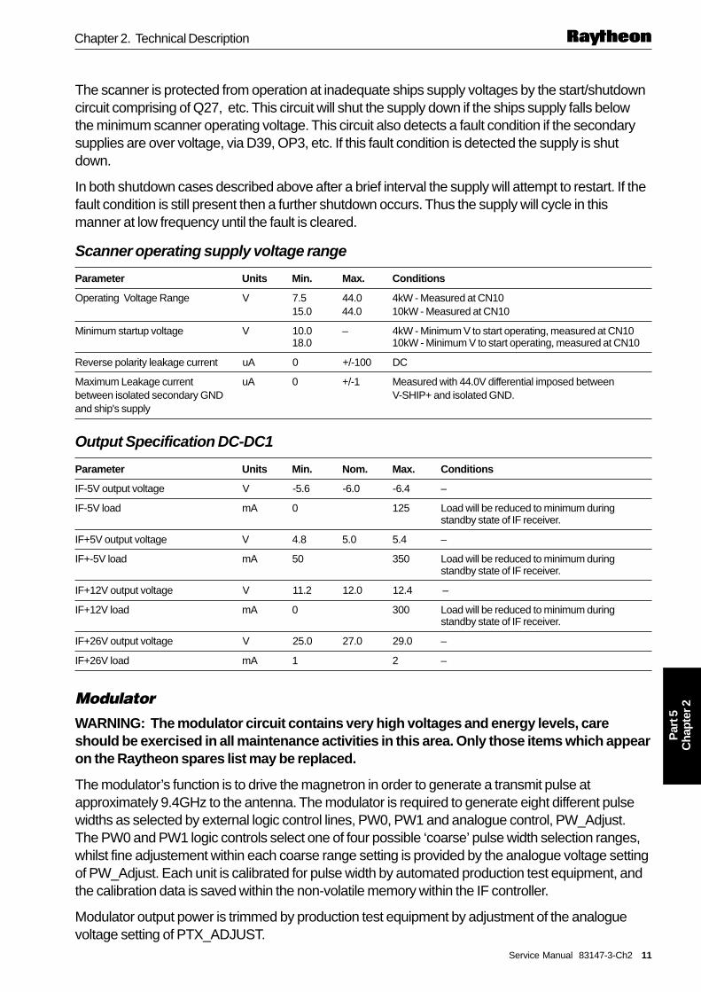
The scanner is protected from operation at inadequate ships supply voltages by the start/shutdowncircuit comprising of Q27, etc. This circuit will shut the supply down if the ships supply falls belowthe minimum scanner operating voltage. This circuit also detects a fault condition if the secondarysupplies are over voltage, via D39, OP3, etc. If this fault condition is detected the supply is shutdown.
In both shutdown cases described above after a brief interval the supply will attempt to restart. If thefault condition is still present then a further shutdown occurs. Thus the supply will cycle in thismanner at low frequency until the fault is cleared.
Scanner operating supply voltage range
Parameter Units Min. Max. Conditions
Operating Voltage Range V 7.5 44.0 4kW - Measured at CN1015.0 44.0 10kW - Measured at CN10
Minimum startup voltage V 10.0 – 4kW - Minimum V to start operating, measured at CN1018.0 10kW - Minimum V to start operating, measured at CN10
Reverse polarity leakage current uA 0 +/-100 DC
Maximum Leakage current uA 0 +/-1 Measured with 44.0V differential imposed betweenbetween isolated secondary GND V-SHIP+ and isolated GND.and ship's supply
Output Specification DC-DC1
Parameter Units Min. Nom. Max. Conditions
IF-5V output voltage V -5.6 -6.0 -6.4 –
IF-5V load mA 0 125 Load will be reduced to minimum duringstandby state of IF receiver.
IF+5V output voltage V 4.8 5.0 5.4 –
IF+-5V load mA 50 350 Load will be reduced to minimum duringstandby state of IF receiver.
IF+12V output voltage V 11.2 12.0 12.4 –
IF+12V load mA 0 300 Load will be reduced to minimum duringstandby state of IF receiver.
IF+26V output voltage V 25.0 27.0 29.0 –
IF+26V load mA 1 2 –
ModulatorWARNING: The modulator circuit contains very high voltages and energy levels, careshould be exercised in all maintenance activities in this area. Only those items which appearon the Raytheon spares list may be replaced.
The modulator’s function is to drive the magnetron in order to generate a transmit pulse atapproximately 9.4GHz to the antenna. The modulator is required to generate eight different pulsewidths as selected by external logic control lines, PW0, PW1 and analogue control, PW_Adjust.The PW0 and PW1 logic controls select one of four possible ‘coarse’ pulse width selection ranges,whilst fine adjustement within each coarse range setting is provided by the analogue voltage settingof PW_Adjust. Each unit is calibrated for pulse width by automated production test equipment, andthe calibration data is saved within the non-volatile memory within the IF controller.
Modulator output power is trimmed by production test equipment by adjustment of the analoguevoltage setting of PTX_ADJUST.

12 Service Manual 83147-3-Ch2
Par
t 5C
hapt
er 2
Pathfinder Radar/Chartplotter Series
The modulator is fired when triggered by the rising edge of the PRI_PLS logic level control signalfrom the micro controller. In addition a further control line RADAR_TX_EN is used to over-ridePRI_PLS and disable transmission when held low (the default state is transmit disabled if the IFcontroller is disconnected). Output sense lines, HEATER_OK and MOD_ISENSE, sense themagnetron heater and transmit currents, indicating correct operation to the external micro controller.
The modulator comprises a high voltage pulse transformer, Tx3 (4kW) or Tx4 (10kW) and aswitching FET Q41 (4 and 10kW) and Q42 (10kW only) together with associated control and pulseshaping circuitry. In operation the control circuitry selects one of eight pulse widths which then drivethe FET gate via IC U13. As the FET turns on it switches the high voltage supply, MOD+HV, acrossthe very low impedance of the pulse transformer primary. The current rapidly rises in the FET(s)and their series source resistors until the FET(s) begin to pinch-off thus holding the current at aconstant level. The resulting primary voltage pulse causes an associated secondary pulse stepped-up by the transformer turns ratio to several kV. When the secondary voltage reaches the magnetronswitch-on threshold it will ‘fire’ generating a burst of microwave power at several kW and at afrequency of approximately 9.4GHz.
The voltage supply to U13, nominally at 18V, is controlled by PTX_ADJUST which allows theprimary current to be trimmed and thus the magnetron current controlled.
The FET(s) are protected from operation at excess temperature by a thermistor, RT1 bonded to theFET heatsink. This functions so as to disable the modulator pulse generation circuitry, U11A, etc, inthe event of excessive heatsink temperature (>100°C). It is further protected from operation with lowor unstable supply voltage by Q29, D26, Q40, etc.
The control circuitry comprises a monostable U11A, whose pulse width is controlled by selection ofone of four capacitor values under control of the logic level PW0, PW1 control lines. Fine adjustmentof pulse width by variable analogue voltage control, PW_Adjust is achieved by varying the effectiveresistance of R262, R263. An additional monostable, U11B limits the maximum pulse repetition rateunder fault conditions.
Table 1: Range, Pulse Width and PRF Table (4kW/10kW)
Range (nm) Nominal PW (ns) PRF (kHz) PW1 state PW0 state Normal Magnetron CourseCurrent Reading Pulse Width
(X = Pulse Expand ON) (see Diagnostics Menu)
1/8 65 3.0 0 0 17 - 40 SP range
1/8X 90 3.0 0 0 30 - 60 SP range
1/4 65 3.0 0 0 17 - 40 SP range
1/4X 90 3.0 0 0 30 - 60 SP range
1/2 90 3.0 0 0 30 - 60 SP range
1/2X 150 3.0 0 1 58 - 94 MP range
3/4 150 3.0 0 1 58 - 94 MP range
3/4X 250 3.0 0 1 84 - 130 MP range1 0 LP range
1.5 350 2.0 1 0 85 - 145 LP range
1.5X 450 1.6 1 0 85 - 145 LP range
3.0 450 1.6 1 0 85 - 145 LP range
3.0X 600 1.2 1 1 85 - 145 VLP range
6.0 or greater 1000 (4kW) 0.74 1 1 80 - 135 VLP range1200 (10kW)

Service Manual 83147-3-Ch2 13
Par
t 5C
hapt
er 2
Chapter 2. Technical Description
Two circuit blocks monitor the performance of the modulator / magnetron to provide diagnosticinformation for service personnel which may be read in the diagnostics menu at the display unit.
• Comparitor U14D senses the correct flow of magnetron heater current and provides an output,HEATER_OK which is normally a logic high when the magnetron is connected and drawing atleast the minimum specified current.
• Peak detector D60, etc detects the peak pulsed magnetron current flow and derives the signalMOD_ISENSE which gives an indication of the transmit power. This circuit is an improvementon that used on the D2 and D4 radome scanners and may be used with some confidence todiagnose correct modulator/magnetron operation. The reading may be found in the displaydiagnostics menu (seeSection 3.3). The value will change with selected range setting. SeeSection 3.6, Diagnostics Menu and Table 1 below, for details.
Modulator Clock, PRI_PLS
PRI_PLS
1/PRF or PRI
3-5V
0-0.5V
10us _+ 0.5us
D4059-2
Figure 7. Modulator clock, PRI_PLS
Ships Heading SensorThe ships heading sensor is used to indicate the antenna alignment. It provides one output pulseper antenna revolution. This information is utilised by the IF receiver to synchronise the radar outputto the ships heading.
A Hall effect transducer is triggered by a magnet on the principal gear of the antenna rotary jointassembly. This results in a negative going pulse at CN5-1. This pulse is conditioned by the interfaceformed by R124, C100 and reappears as SHP_IN at CN2-15 as a negative going pulse ofapproximately 5V amplitude. If the antenna is rotating normally this pulse will have a repetition rateof approximately 2.5 seconds.
3-Phase DC Brushless Motor ControllerAll open array radar systems use a 3-phase DC motor. The controller for this motor is based on anintegrated controller IC, U4. This IC provides electronic commutation of each of the three motorphase windings. Three hall effect transducers embedded within the motor signal the position of therotor. These signals RLG1, RLG2, RLG3 are then interpreted by U4 to signal which motor phasesare to be driven by the 3-phase bridge formed by Q5/Q14, Q9/Q15 and Q13/Q16. The motor Halltransducer signals are combined by U1, U2A to provide antenna position feedback to the IFcontroller. When rotating normally at 24 rpm, the signal at TP34 and CN2-10 (STEP_IO) should bea logic level clock at approximately 590 Hz. In addition the hall transducer signals are used to deriverotation speed feedback via U1, U2A and U3C. The output of filter U3C is a DC voltage proportionalto motor speed. The desired speed is set by potentiometer RV1 and is set to establish a motorspeed of 2900 RPM. Motor over-speed is detected by U3D which enables motor braking tominimise overun speed in high wind conditions. Motor torque control is achieved by controlling theswitching duty cycle of the 3-phase bridge, bottom FETs, Q14, Q15, Q16. This pulse widthmodulated control operates at approximately 25kHz. Each 'on' cycle may also be terminated

14 Service Manual 83147-3-Ch2
Par
t 5C
hapt
er 2
Pathfinder Radar/Chartplotter Series
prematurely by peak motor current detected by R102, if the peak winding current threshhold isexceeded (approximately 13 A).
Fault conditions such as incorrect hall transducer inputs or excessive motor current are detected byU4 and signalled at pin 14. This fault signal is conditioned and timed by monostable U2, U3B, etc.and in the event of a persistent fault of approximately 10 seconds duration the motor controller isdisabled and latched off. Thus an obstructed antenna will cease to drive after this period. Thiscondition will also be detected by the IF controller microprocessor and transmission will be disabled.Once latched OFF the motor circuit will remain off until either the radar power button is pressed toswitch the mode back to 'transmit', or the power is cycled.
Note: The motor controller circuit is referenced to ship's battery negative.
2.4 IF Receiver PCB – Interface DescriptionThe Interfaces to the IF Receiver are shown in Figure 4.
The individual signal functions are described below:-
Connectors
Connector Function Type
P1 LNC connector 20 way SAMTEC CLH-110-F-D-DV-P(7 pins used only)
P2 Display connector for serial 10 way Picoflex ribbon connectorcommunications, video andsynchronisation timing signals
P4 Mod-IF interconnect 18 way Picoflex ribbon connector
Display Connector (P2)
Ref. Signal Name Colour Type State Function
P2-1 AZ_SHP_OUTB Grey Clock, Normally high, low going clock A differential output pair providingP2-2 AZ_SHP_OUT Purple differential pair Normally low, high going clock azimuth pulses to synchronise antenna
output 0 - 5.0V position with the display (10us durationat approximately 820 Hz). The SHP(ships heading position) pulse issuperimposed on the signal once perantenna revolution (30us pulse every2.5 secs)
P2-3 SER_IOB Blue Digital comms, 2.2 V nom. DC bias An RS485 Bi-directional serialP2-4 SER_IO Green differential pair 2.8 V nom. DC bias communications link operating at 19.2
bi-directional kBaud. It provides control of thescanner operation and monitoringfunctions from the Radar display.
P2-5 PRI_OUTB Orange Clock, normally low, high going clock A differential output pair providing PRIP2-6 PRI_OUT Yellow differential pair normally high, low going clock (Pulse Repetition Interval) pulses to
output 0 - 5.0V synchronise the firing of the transmitterwith the display video. Rate isaccordingto range setting.
P2-7 Spare Not used
P2-8 VIDEO GND Analogue Video AC coupled 1.75V max peak The raw Radar video signal from theP2-9 VIDEO output signal into 75 ohms scanner.
P2-10 GND

Service Manual 83147-3-Ch2 15
Par
t 5C
hapt
er 2
Chapter 2. Technical Description
AZ_SHP_OUTB
approximately 1.2ms
3-5V
0-0.5V
10us _+ 0.5us
D4061-1
Figure 8. AZ_SHP_OUTB / AZIM_DNEG
AZ_SHP_OUT
approximately 1.2ms
3-5V
0-0.5V
10us _+ 0.5us
D4062-1
Figure 9. AZ_SHP_OUT / AZIM_DPOS
PRI_OUT
1/PRF or PRI
3-5V
0-0.5V
10us _+ 0.5us
D4063-2
Figure 10. PRI_OUT / PRI_DPOS
PRI_OUTB
3-5V
0-0.5V
10us _+ 0.5us1/PRF or PRI
D4064-2
Figure 11. PRI_OUTB / PRI_DNEG
LNC Connector (P1)
Ref. Signal Name Type State Function
P1-1 GND 60MHz Intermediate N/A The down-converted received radar signalP1-2 60MHz IF Frequency (IF) from the LNC at 60MHz carrier frequency.
Radar receivedsignal input
P1-3 Not Connected N/A N/A N/A
P1-4 RF_ATTENV Analogue control 0 - 10V N/Avoltage output
P1-5 TUNE_V Analogue control 4 - 24 V A control voltage that is applied to the LNCvoltage output VCO (Voltage Controlled Oscillator) to
maintain the tuning of the LNC output to60MHz.
P1-6 GND Analogue output 0V Analogue ground reference for the LNCsupplies.
P1-7 +5V Analogue Output 0V in standby mode The 5v supply for the LNC. It is switched off(switchable) +5V in transmit mode in standby mode to save power.
P1-8 -5V Analogue Output -5.9V nom. The -5.9V supply for the LNC

16 Service Manual 83147-3-Ch2
Par
t 5C
hapt
er 2
Pathfinder Radar/Chartplotter Series
-5V GND RF_ATTENV GND
+5V TUNE_V N/C 60MHzIFD4065-1
Figure 12. LNC Connector P1 connections as viewed from component side of board
Mod / IF Interconnect (P4)This connector P4 is pin to pin identical to CN2 connector on the MOD / PSU PCB. See MOD / PSUinterface section for details.
2.5 IF Receiver – Circuit Description
Main ReceiverThe prime function of the IF receiver is to provide low noise amplification and logarithmic detectionof the 60MHz IF (Intermediate Frequency) Radar received signal, to give a video signal outputsuitable for displaying on the Radar screen (after digital processing at the display).
The receiver provides low noise amplification, dynamic IF gain control (STC) and selectable IFbandwidths to optimise target detection for all ranges and for various sea and weather conditions.The following summarises the functions of the circuitry.
A low noise amplifier (AR1), is situated prior to an adjustable gain monolithic microwave integratedcircuit (MMIC) amplifier stage (U9 and U10) in order to define the noise figure of the system. Thisincorporates the relevant circuitry to provide fast gain control via the STC generator.
General amplification and attenuation control is also provided by the cascaded MMIC amplifiers U9and U10 in conjunction with factory-tuned inductors (L4, L10 and L11) and capacitors to tailor thebandwidth characteristics of the circuit.
IF Bandwidth switching between 12MHz and 3MHz is configured to provide matched filtering for theshorter transmit pulses which are automatically set when the Radar range is adjusted. Gain isincreased accordingly to maintain a relatively constant noise power at the receiver output.
Switched video filters are used in conjunction with the 3MHz IF filter to provide matched filtering forthe 600ns and 1us/1.2us pulses. These are 0.7 MHz and 0.5MHz respectively.
Remaining variations in noise power as a consequence of the different signal bandwidths (i.e. noisepower is directly proportional to bandwidth) are adjusted in the display.
A ‘fast time constant’ circuit is used to provide a continuously variable high pass filter to providesome immunity against the bulk effects of rain.
N.B. The variable inductor coils L4, L10 and L11 are preset at the factory. They requirespecialist equipment for tuning and must not be adjusted by the service engineer.
The PRI rates and video noise can be observed at the appropriate connectors (see interfacesection) for the different range settings as follows:

Service Manual 83147-3-Ch2 17
Par
t 5C
hapt
er 2
Chapter 2. Technical Description
Summary of bandwidths, pulse widths and PRI rates
Radar Range Setting IF BW Video BW Pulse width used Video Noise level
0.125 to 0.75 nm 12MHz 15MHz 65 to 250ns >500mV pk-pk
1.5 and 3nm 3MHz 15MHz 350 and 450ns >500mV pk-pk
3nm (target expand) 3MHz 0.7MHz 600ns >250mV pk-pk
6nm to max range 3MHz 0.5MHz 1us/1.2us >200mV pk-pk
Autotune ReceiverThe autotune receiver provides frequency selective peak detection of high level ‘main-bang’transmitter pulses. This is achieved using a high impedance branch from the main receiver inputwith a transistor/diode based amplifier/detector circuit (Q31, Q32, D16, Q33, Q37). The detectionbandwidth of the autotune receiver is set at the factory using variable inductors L7, L8 and L9. Theoutput of the receiver is buffered (U6A) and passed to the scanner microprocessor. A tuningalgorithm is then performed at the display to set the difference frequency between the magnetronand VCO (Voltage Controlled Oscillator) to a fixed IF frequency of 60MHz using the TUNE_Vcontrol line P1 pin5. Both coarse and fine adjustment are provided by the microprocessor to allowfor initial setting and subsequent fine tuning.
N.B. The variable inductor coils L7, L8 and L9 are preset at the factory. They requirespecialist equipment for tuning and must not be adjusted by the service engineer.
STC/Main Bang Suppression (MBS)The STC circuitry consists of a logarithmic function generator split into four outputs and multiplied by4, 5.5 and 2 to generate the respective R4, sea clutter and rain curves respectively.
These curves are offset as requested via processor/operator demands and then combined toprovide an output equal to the greatest of the inputs. A curve splitter and linearisation circuits areused to match the output control levels to the characteristics of each attenuator.
Sea clutter - R5.5 decay
STC - R4 decay
Rain clutter - R2 decay
Fixed gain
TimeCombined curve generated as an output equal to the greatest of the inputs
MBS
General STC Characteristics
Curve amplitudevariations
DecreasingAttenuation
D4650-2
Figure 13. General STC Characteristics
Main bang suppression (MBS) amplitude and duration controls are configured so as to overridethese STC controls.
For low values of attenuation the attenuation is applied to the Monolithic amplifiers in order topreserve system noise figure. At higher values of attenuation the attenuation is divided between theIF pin attenuator (D17) used to control the first IF amplifier stage, and the Monolithic amplifiers.

18 Service Manual 83147-3-Ch2
Par
t 5C
hapt
er 2
Pathfinder Radar/Chartplotter Series
MicrocontrollerThe microcontroller subsystem, using an NEC 78054 device, is integrated onto the IF receiverboard and provides the following functions :-
• Generates analogue control voltages via a multi channel Digital to Analogue Connector (DAC)for all user and automated scanner adjustments
• Reads the tune indicator input and adjusts tune control voltage as necessary.
• Controls modulator pulse width selection, by selecting PW0 and PW1 control lines (coarse PWadjustment) and then adjusting the analogue output (fine PW adjustment). See Warning below.
• Generates Azimuth pulses synchronised to the 3-phase motor for display synchronisation.
• Generates the PRI (Pulse Repetition Interval) pulses to fire the magnetron, start the STC cycleand synchronise the display.
• Buffers the Ships Heading Pulse from the MOD/PSU PCB for synchronising the display.
• Communicates with the display via a serial interface.
Initial Scanner set up (EEprom stored values)The scanner has non volatile storage (EEprom U18) for the following items:-
• Optimum VCO coarse and fine tune settings.
• Calibrated values for setting each of the 8 transmit pulse widths. See Warning below.
• Default values for the Auto Gain function for each pulse width (used when GST is selected forthe display).
• MBS Duration and Amplitude for each pulse length.
• Range Zero Offset (adjusted by Display Timing function in Advanced settings Menu) for eachfilter setting
• Azimuth zero offset (adjusted by Bearing Alignment function in Radar Set Up Menu)
• STC Preset Max - a preset level of R4 clutter curve is set to equalise close target returns
• Scanner Size - storage of the antenna size fitted to the Scanner - used to set Max Range forDisplay
• Modulator Power - The power of the modulator in kW - also used to set Max range for Display
WARNING: The IF PCBs for the 4kW and 10kW Scanners are not interchangeable. Thestored pulse width setting are different. If a 4kW IF PCB is fitted to a 10kW Scannerpermanent damage will occur to the Modulator output FETs due excessive pulse duration athigh PRFs.
The above stored parameters each have a factory set and used working location. These values areset at the factory and are optimised for each individual scanner unit to provide optimumperformance and a good starting value when the Radar system is first operated. However, the VCOtuning, range zero offset and Azimuth zero offset used working values are adjustable from thedisplay during Radar operation.
Due to temperature variations affecting the LNC, the VCO tuning values are adjusted by the displaywhen Auto mode is selected to give optimum tuning. The present optimum value is stored when arange change (i.e. transmit pulse length change) is made, so that when the range is selected again,
Service Manual 83147-3-Ch2 19
Par
t 5C
hapt
er 2
Chapter 2. Technical Description
the auto-tune function is at a better starting point. Normally this adjustment is made just to the finetune value for each pulse length. Occasionally, a change in coarse tune may be necessary. If tuningproblems occur, the Tune Preset function in the Advanced Settings Menu provides a manual way ofadjusting the coarse tune used working value.
The Range Zero Offset is adjusted manually from the display Advanced Settings Menu (DisplayTiming) as part of the normal Radar installation procedure. If the inter unit cable is kept to thesupplied length the Display Timing should not normally need adjusting.
STC preset maximum is set at the factory, however the STC preset value can also be changed viathe Advanced Settings Menu.
When a Factory Reset is performed (press MENU, select SYSTEM SET UP, then press and holdMENU for 5 second countdown) the scanner copies the Factory set values back into the usedworking locations of the EEprom so the scanner and display are as they were set up when they leftthe factory.
The EEprom also stores the scanner Build Standard information that is accessible through theDiagnostics Menu - see chapter 4 - fault finding.
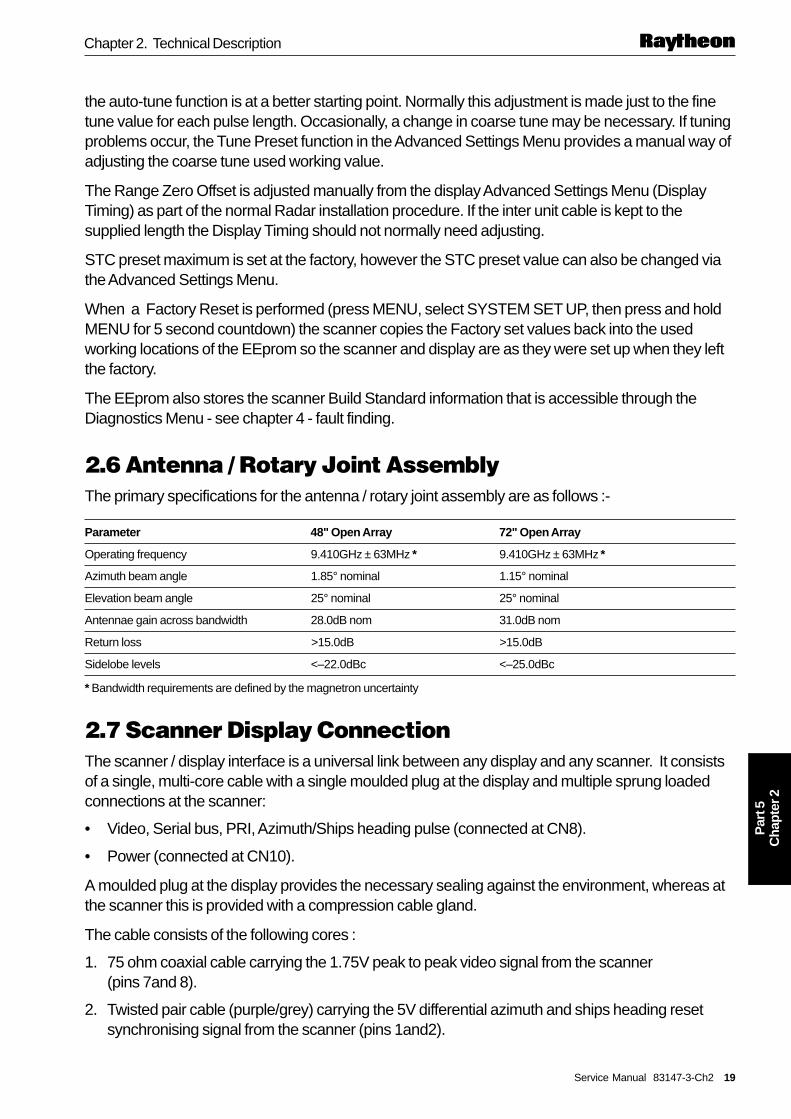
2.6 Antenna / Rotary Joint AssemblyThe primary specifications for the antenna / rotary joint assembly are as follows :-
Parameter 48" Open Array 72" Open Array
Operating frequency 9.410GHz ± 63MHz * 9.410GHz ± 63MHz *
Azimuth beam angle 1.85° nominal 1.15° nominal
Elevation beam angle 25° nominal 25° nominal
Antennae gain across bandwidth 28.0dB nom 31.0dB nom
Return loss >15.0dB >15.0dB
Sidelobe levels <–22.0dBc <–25.0dBc
* Bandwidth requirements are defined by the magnetron uncertainty
2.7 Scanner Display ConnectionThe scanner / display interface is a universal link between any display and any scanner. It consistsof a single, multi-core cable with a single moulded plug at the display and multiple sprung loadedconnections at the scanner:
• Video, Serial bus, PRI, Azimuth/Ships heading pulse (connected at CN8).
• Power (connected at CN10).
A moulded plug at the display provides the necessary sealing against the environment, whereas atthe scanner this is provided with a compression cable gland.
The cable consists of the following cores :
1. 75 ohm coaxial cable carrying the 1.75V peak to peak video signal from the scanner(pins 7and 8).
2. Twisted pair cable (purple/grey) carrying the 5V differential azimuth and ships heading resetsynchronising signal from the scanner (pins 1and2).

20 Service Manual 83147-3-Ch2
Par
t 5C
hapt
er 2
Pathfinder Radar/Chartplotter Series
3. Twisted pair cable (yellow/orange)carrying 5V differential PRI pulse synchronising signal fromthe scanner (pins 5 and 6).
4. Twisted pair cable (green/blue) carrying 5V differential, bi-directional serial communicationssignal (RS485) between scanner and display (pins 3and4).
5. DC ships power to scanner(4 cores)

Service Manual 83147-3-Ch3 21
Par
t 5C
hapt
er 3
Chapter 3. Fault Finding
Chapter 3. Fault FindingThis chapter details the fault finding and repair issues for the Open Array Scanner Units.
Please read the 3.1 Safety Notices and 3.2 General Notes below before commencing a serviceoperation. You should also read the 3.3 Built-in Testing/Diagnostics section as this will be of use inmany cases. Begin the fault finding procedure by refering to the System Trouble-shooting CheckList in Part 1, Section 3.5 which will advise on the appropriate course of action.
3.1 Safety NoticesThe following checks are intended only for qualified service technicians.
The radar scanner contains DANGEROUS HIGH VOLTAGES in the vicinity of thehigh voltage power supply unit, Modulator and magnetron connections.
The display unit also contains DANGEROUS HIGH VOLTAGES. The CRTdisplays have voltages of 11 kV and the LCD displays have voltages in excess of700 V.
The radar scanner emits non-ionising radiation from the magnetron, circulator andantenna assemblies. There are also low levels of ionising radiation (x-rays) inclose proximity to the magnetron when it is transmitting. It should not be operatedin transmit mode near to any persons, or within enclosed buildings.
The scanner also contains energy storage elements some at DANGEROUS HIGH VOLTAGEScapable of delivering very high currents (in excess of 100A) if accidentally short circuited. Theservice technician is strongly cautioned to avoid powering the scanner unit during service, unlessabsolutely necessary and to take particular care if working on the scanner unit if fixed to a mast. Inaddition the scanner contains rotating parts which develop considerable torque and may representa danger if the unit is powered during service. The scanner Safety Switch should always be setto the OFF position when working on, or near the scanner unit, except for specific tests detailedin this Service Manual.
The radar pedestal is heavy (24 kg). If it becomes necessary to remove the pedestal, ensure thatthe safety lifting procedures detailed in the installation chapter of the Owner's Handbook areemployed. The core assembly which contains all the electronic circuits is easy to remove and this ismore convenient for most service operations. Removal of the core assembly also gives access tothe motor gearbox assembly.
3.2 General Notes1. See Replacement of Parts notes, photographs and exploded views in Chapter 5 for guidance in
dismantling of the radar.
2. The Connector / pin labelling convention used in this manual is as follows :J4-6 means ‘connector J4, pin 6’.
3. When measurements to Picoflex ribbon cable connectors are specified, these can usually bemade by carefully probing the slots in the cable connector. Pin 1 is marked by the red cablestripe.
4. Video Noise tests. A number of diagnostic procedures make reference to whether video noisecan be observed. The procedure for verifying this is as follows: With the Sea Clutter and Gain set
DANGERNon-ionising Radiation
22 Service Manual 83147-3-Ch3
Par
t 5C
hapt
er 3
Pathfinder Radar/Chartplotter Series
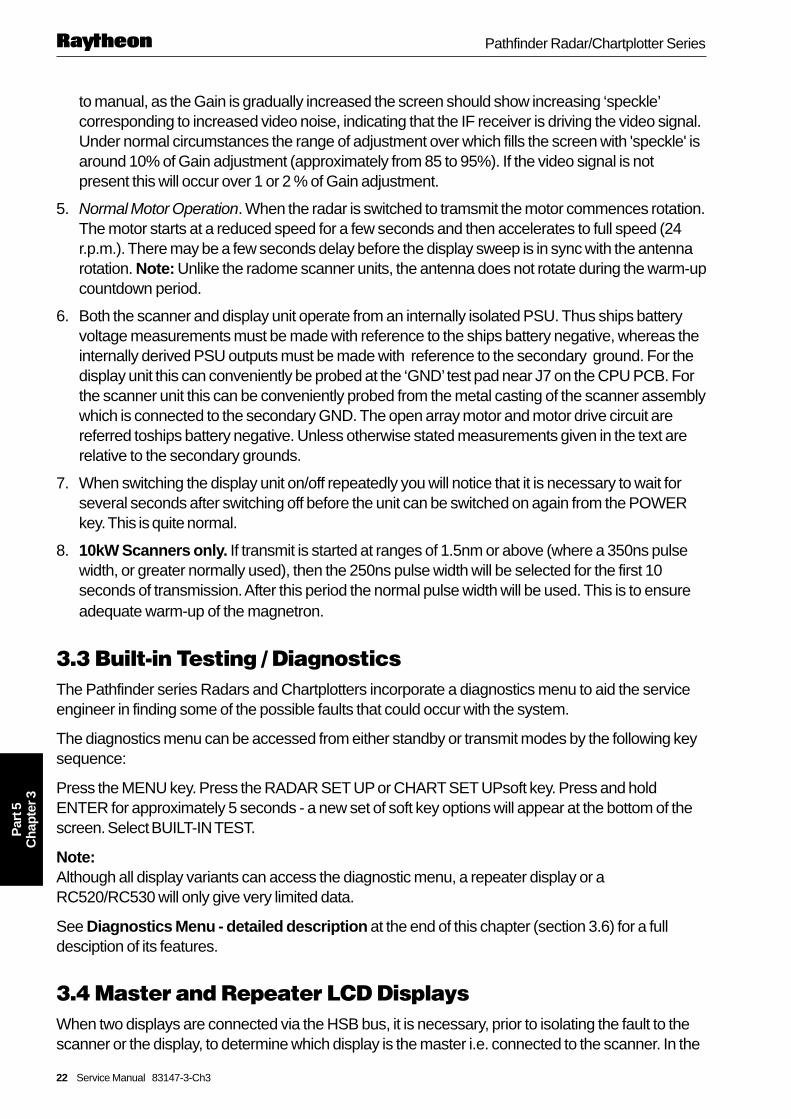
to manual, as the Gain is gradually increased the screen should show increasing ‘speckle’corresponding to increased video noise, indicating that the IF receiver is driving the video signal.Under normal circumstances the range of adjustment over which fills the screen with 'speckle' isaround 10% of Gain adjustment (approximately from 85 to 95%). If the video signal is notpresent this will occur over 1 or 2 % of Gain adjustment.
5. Normal Motor Operation. When the radar is switched to tramsmit the motor commences rotation.The motor starts at a reduced speed for a few seconds and then accelerates to full speed (24r.p.m.). There may be a few seconds delay before the display sweep is in sync with the antennarotation. Note: Unlike the radome scanner units, the antenna does not rotate during the warm-upcountdown period.
6. Both the scanner and display unit operate from an internally isolated PSU. Thus ships batteryvoltage measurements must be made with reference to the ships battery negative, whereas theinternally derived PSU outputs must be made with reference to the secondary ground. For thedisplay unit this can conveniently be probed at the ‘GND’ test pad near J7 on the CPU PCB. Forthe scanner unit this can be conveniently probed from the metal casting of the scanner assemblywhich is connected to the secondary GND. The open array motor and motor drive circuit arereferred toships battery negative. Unless otherwise stated measurements given in the text arerelative to the secondary grounds.
7. When switching the display unit on/off repeatedly you will notice that it is necessary to wait forseveral seconds after switching off before the unit can be switched on again from the POWERkey. This is quite normal.
8. 10kW Scanners only. If transmit is started at ranges of 1.5nm or above (where a 350ns pulsewidth, or greater normally used), then the 250ns pulse width will be selected for the first 10seconds of transmission. After this period the normal pulse width will be used. This is to ensureadequate warm-up of the magnetron.
3.3 Built-in Testing / DiagnosticsThe Pathfinder series Radars and Chartplotters incorporate a diagnostics menu to aid the serviceengineer in finding some of the possible faults that could occur with the system.
The diagnostics menu can be accessed from either standby or transmit modes by the following keysequence:
Press the MENU key. Press the RADAR SET UP or CHART SET UPsoft key. Press and holdENTER for approximately 5 seconds - a new set of soft key options will appear at the bottom of thescreen. Select BUILT-IN TEST.
Note:Although all display variants can access the diagnostic menu, a repeater display or aRC520/RC530 will only give very limited data.
See Diagnostics Menu - detailed description at the end of this chapter (section 3.6) for a fulldesciption of its features.
3.4 Master and Repeater LCD DisplaysWhen two displays are connected via the HSB bus, it is necessary, prior to isolating the fault to thescanner or the display, to determine which display is the master i.e. connected to the scanner. In the

Service Manual 83147-3-Ch3 23
Par
t 5C
hapt
er 3
Chapter 3. Fault Finding
event that the rear of the units are not easily accessible, then this may be determined by poweringboth displays on and waiting for the WARMING UP banner to count down to zero.
Power one of the two units off.
A message HSB LOST will be displayed and the alarm will sound on the other unit for about 5 seconds. Ifthis unit then shows the message STANDBY it is the Master display.
It will be possible to use scanner from the master display.
If the unit remaining powered up is the repeater, again a message HSB LOST will be displayed, andthe alarm will sound for about 5 seconds. If the unit then displays SCANNER NOT RESPONDINGthen it is either a slave or the scanner is faulty. Repeat the procedure above on the other unit todetermine if the fault is in the repeater or the scanner.
3.5 Check Lists
Check List 2
SCANNER NOT RESPONDING message displayed or Start-up count-down restarts unexpectedly
External Checks1. Check the inter-unit scanner cable is correctly fitted and pushed home at the rear of the display unit.
4
D4083-1
2
5
8
11
13
10
1
3
6
9
7
12
Figure 14. Scanner cable end connector
No. Function Colour
1 I/F Video information from scanner Coaxial inner
2 I/F Video ground Coaxial outer
3 Battery negative (filtered) to scanner Black
4 Transmit trigger pulses from scanner Orange
5 Battery negative (filtered) to scanner Black
6 Command/data link to/from scanner Green
7 Transmit trigger pulses Yellow
8 Screen No insulation
9 Battery positive (filtered, switched) to scanner Red
10 Command/data link to/from scanner Blue
11 Battery positive (filtered, switched) to scanner Red
12 Azimuth and ship’s heading pulses from scanner Violet
13 Azimuth and ship’s heading pulses from scanner Grey

24 Service Manual 83147-3-Ch3
Par
t 5C
hapt
er 3
Pathfinder Radar/Chartplotter Series
Check List 2 continued2. Check the scanner cable for signs of damage / corrosion.
3. Check the unit is correctly supplied with power:Voltage at the display power cable socket (pins 3 and 5) is between 10.7 and 44 V (4 kW), or 18and 44 V (10kW). If not check the integrity of the power cabling to the radar system, particularlythe power cabling to the display all the way through to the battery.
4. If the radar operates normally until put into transmit mode, then suspect the power cablingparticularly on 12V (4kW) systems. The antenna may be seen to start and then stop after part ofa rotation. Open array radar systems consume considerable power and require a good quality,low resistance power source. When the radar motor starts a current surge occurs which willcause the scanner to trip if the ship's supply is inadequate. Refer to the installation chapter of theOwner's Handbook for details.
5. It is also possible that the antenna is not free to rotate, causing excessive motor current. To checkthis switch the system off and rotate the antenna by hand. It should turn freely throughout the full360° of rotation. If it does not refer to Check List 13. Note: When power is applied to the radarand it is in 'standby' it will be difficult to rotate the antenna by hand as the motor will be in 'brake'mode.
6. With scanner cable removed measure the supply voltage on display cable plug at the rear of thedisplay unit and check it reads between 10.7V and 32 V(4 kW), or 18V and 44 V (10 kW).Note the power pins may be identified by their larger diameter compared to the signal pins. If thevoltage is incorrect see Display Check 1 on following page.
7. Now check scanner communications link. With scanner cable disconnected from rear of displaymeasure resistance between pins 6 and 10 of scanner cable plug. A reading of approximately160 ohms should be obtained. If not see Scanner Check 1 on following page.
8. Now check display communications link:With scanner and power cables disconnected from rear of display measure resistance betweenpins 6 and 10 of the scanner cable plug at the rear of the display. A reading of approximately 160ohms should be obtained. If not see Display Check 2 on following page.
9. Turn the display unit on with the scanner disconnected. Wait until the “scanner not responding”message appears then enter the Diagnostics menu. Check the Display Comms test result. Apass indicates the display is probably OK and the fault lies in the scanner power supply orcommunications link.
10.With the scanner cable still disconnected, set the scanner safety switch to OFF and open thepedestal to gain access to the microwave core. Ensure the stay is locked into position to preventaccidental closure. Remove the motor plug, CN3, from the Modulator PCB, so that the motorcannot operate and reconnect the scanner cable. Switch the display on but ENSURE THAT IT ISNOT IN THE TRANSMIT MODE. With the scanner safety switch still in the OFF position checkthe ship's supply voltage at CN10 on the Modulator PCB is greater than 10 V (4 kW), or 18 V(10 kW). If a lower voltage is measured, then the likely cause of the fault is damage or corrosionproblems to the scanner cable. Repair or replace the cable. If the voltage is OK, switch thescanner safety switch to ON and remeasure the voltage at CN10. If the voltage measuresgreater than 10 V (4 kW), or 18 V (10 kW) then see Scanner Check 2, or if the displaycountdown starts unexpectedly then see Display Check 3. If the voltage measured was low,repair or replace the scanner cable.

Service Manual 83147-3-Ch3 25
Par
t 5C
hapt
er 3
Chapter 3. Fault Finding
11.An excessive voltage drop could also be due to the scanner drawing excess current. If there isjust a simple communications fault, all the scanner functions will be off and it will consumeapproximately 9.5 Watts, or less. e.g. at 10.0 V it would draw 0.95Amps, or less. Use an ammeterto measure the current drawn at CN10 and hence calculate the power. (Remember to removeboth power cores of the same polarity to make the measurement) If the power is OK thenproceed with Scanner Check 1. If the power consumption is excessive then proceed withScanner Check 2.
Display Circuit OperationThe ships supply connects on the PSU board via solder buckets to the rear panel connector. Poweris applied to the units PSU when the internal relay closes. The relay is driven by either the power keyvia circuitry on the CPU board, or by the micro itself. Thus initial switch on occurs when the powerkey is depressed, causing the relay to close. The software then runs and holds the relay closed. Atswitch-off the software shuts the unit down, then opens the relay.
Display Internal Checks For all the following internal checks, with the display unit opened out and with all connectors still inplace, attach a ships power cable to the rear panel connector and switch the supply on.
Display Check 1 - Display has no power at scanner plug at rear of display1. Check that the power reaches the Power / NMEA connector solder buckets on the Rear
Connector/PSU board. If not then there is a failure of the power / NMEA connector. The batterypower pins are those with the thick pcb tracks running to them. If an incorrect voltage ismeasured then disassemble the rear cover assembly and check the rear panel connector forsigns of corrosion / damage.
Display Check 2 - Display communications check1. Check resistance at CPU board connector J4 between J4-11 and J4-12 is approximately 160 �.
If so there must be a cable fault either on the Rear Connector/PSU board, or ribbon cable toCPU J4. Check for damage or corrosion and replace as necessary.
Display Check 3 - Display countdown restarts unexpectedly1. Check that the Power cable between the Rear Connecto/PSU board PL7 and the CPU board J7
(LCD displays), or Scan/PSU board CN4 is connected, with no breaks in any cores.
2. Power the display and press the Power key. With a ground reference on J7- 2, PGND, of thecable check that the voltages shown in Checklist 10 for CPU Power - J7 are present. If all arecorrect then proceed to next test, else there is a failure of the PSU PCB.
Scanner Internal Checks Switch the radar OFF and isolate from the ship's power supply. Also set the scanner safety switch toOFF. Many of the checks below may be carried out on the scanner with the pedestal hinged open. Inthis case ensure that the motor cable is unplugged at the Modulator PCB, CN3 to ensure the motorcannot operate. If preferred the microwave core which contains the electronic circuits and themagnetron may simply be removed to a safe location, where it can be worked upon. Refer tochapter 5 for dismantling instructions.

26 Service Manual 83147-3-Ch3
Par
t 5C
hapt
er 3
Pathfinder Radar/Chartplotter Series
Check List 2 continued
GreyPurpleBlueGreenYellowOrangeCoaxial Screen (Black)Coaxial Inner (White)
Signal connector
Power connector
D4576-1
Figure 15. Modulator PCB connector CN8.
Scanner Check 1 - Scanner communications checklistEnsure the radar is switched OFF and disconnected.
1. Check connections at scanner 8-way connector, CN8, with the pedestal hinged open.Particularly check pin 3 (blue) and pin 4 (green) for damage or corrosion. If faulty remove coresfrom spring loaded connector CN8, restrip and re-insert.
2. Measure resistance between 8-way Molex connector, SK1-3 and SK1-4 and check forapproximately 160 ohms. If correct then fault must lie within the inter-unit scanner cable, replace.If the resistance is wrong then the fault may lie in either the ribbon cable assembly connected tothe Modulator PCB at CN7, or the IF PCB. To check remove the Modulator PCB and IF PCB andrecheck the measurement at PL2-3 and PL2-4 on the IF PCB. If OK, then replace the ribboncable. If the measurement is still wrong then replace the IF PCB.
Scanner Check 2 - Scanner power checklistWARNING: The Modulator PCB contains DANGEROUS HIGH VOLTAGES. See SafetyNotices before proceeding. The high voltage area is marked with a thick line on the PCB.Avoid all contact with this area when the unit is powered and for at least 2 minutes afterpower is removed to allow high voltage capacitors to discharge.
1. Check the internal receiver power supplies on the Mod/PSU. These are accessible by removingthe microwave core bottom plate, to allow access to the underside of the Modulator PCB, whichmay remain in place. Switch ON and set the scanner Safety switch to ON. Measure the "+5V"supply at the labelled point with respect to chassis. Check if it is in the range 4.7 to 5.3V. (Note theModulator PCB is conformally coated and a sharp test probe may be necessary to gain contactwith the test point) If OK proceed to the next test, otherwise check that the scanner safety switchis OK by shorting CN9-1 and CN9-2. If +5V is now OK repair or replace the switch assembly.

Service Manual 83147-3-Ch3 27
Par
t 5C
hapt
er 3
Chapter 3. Fault Finding
Next switch OFF the radar and isolate from the ship's power supply. Remove the Modulator PCBsecuring screws and hinge the PCB out to disconnect the ribbon cable CN2 to the IF PCB.Replace the Modulator PCB with enough screws to hold it safely in position. Switch ON andrecheck the +5V. If now OK replace IF PCB, otherwise switch the radar OFF and unplug themagnetron at CN6 (connector under rubber boot). Switch ON and recheck the +5V. If OK themagnetron heater may be short circuit, otherwise replace the Modulator PCB.
2. Check power to IF PCB. Switch OFF the radar and isolate from the ship's power supply. RemoveIF metal cover plate and check the continuity of the 18-way ribbon cable from CN2 to P4, on pins2, 5 and 7. If OK the IF receiver is assumed to have a faulty communications circuit and shouldbe replaced. Otherwise replace the ribbon cable assembly connected to P4/CN2.
Check List 3
Radar Target Image blank / faulty (missing radar targets, no radarscan, poor performance, etc.)
External Checks1. Check that the display software is compatible with the open array scanner. Refer to 3.5 System
Trouble-shooting Check List in Part 1.
2. Check that the antenna is rotating when in transmit 'mode'. If not see Check List 13. Check thesettings for Sea Clutter, Rain Clutter and FTC are set to zero (set to manual control if necessary).Set the Gain and Tune to Auto. Set the range to 3 nm and leave the radar running for 5 minutes toallow it to self tune. If the radar image recovers, then switch to each setting in turn, especially the1/8 nm and leave running for at least 1 minute. If the picture is still OK, then check the function ofSea Clutter, Rain Clutter and FTC individually to verify normal operation. If OK then the radar isOK and may have lost pictures due to inappropriate setting of controls. If the picture is still faultyproceed to the next test.
2. It may be desirable to carry out a full Reset of the Radar system before continuing with thechecks, indeed this may cure the fault. Note however that this will also reset Bearing Alignment,Display Timing, Tune and STC Preset to their factory defaults, and therefore these may need tobe set up again as for a new installation.
To perform a system reset:- Power-up the radar system and allow the 70 second countdown period to complete.- Press MENU and select SYSTEM SET-UP.- Press and hold the MENU key until the Reset countdown has reached zero. Release the key,the radar system will reset and restart the 70 second countdown.- The scanner has now been reset to factory settings.- Check if the fault symptoms have disappeared.
3. If there are no radar targets visible, or targets are weak or intermittent, the Debug Box facilityshould help to diagnose the cause of the problem.

28 Service Manual 83147-3-Ch3
Par
t 5C
hapt
er 3
Pathfinder Radar/Chartplotter Series
Switch the Debug Box on by pressing MENU and RADAR SET UP. Then press and holdCLEAR for 5 seconds and select DEBUG BOX ON. The Debug Box will appear on the screenand, if necessary, can be repositioned in the same way as any Data Box. The DEBUG INFOdisplays 5 values as follows:
S Sea Clutter value. Present Sea Clutter set by the display. (Manual slider setting 0% = 90in Debug Box, 100% = 180. In Auto Sea maximum value can be higher)
G Gain value. Present Gain value set by display. (Manual slider setting 0% = 131 in DebugBox, 100% = 191)
C Coarse Tune value. Current Coarse Tune setting that the display is using to tune theLNC in the scanner.
F Fine Tune value. Current fine tune setting that the display is using to tune the LNC in thescanner. (Manual slider 0% = 0 in Debug Box, 100% = 255)
S Signal Strength value. Present signal strength reading the IF PCB is measuringfromthe LNC. Indicates how well the LNC is tuned, the higher the number the better. This isalso the value shown in the ‘tuning bar’ when in manual tune.
Select transmit, Auto TUNE, manual GAIN (set to 80%) and manual SEA (set to 0%).
The Signal Strength value should reach a maximum after the first few rotations of the antennaand are typically 100 +/-20% on 1/8 to ¾ nm ranges, increasing to 130 +/-20% on 1.5 nm rangeand above. The Coarse Tune value should be constant and the Fine Tune value will adjust up ordown by 1 or 2 until the best tuning is achieved (maximum Signal Strength value). This may take12 or more rotations. At this point the F value will remain constant unless the average signalstrength falls by more than 10%, when the F value will be readjusted.
If the Debug Box values are normal, but there are no radar targets visible, a break in theconnection between the IF PCB and the display unit is indicated. Check the Video Test in theDiagnostic Menu, Section 3.6. A FAIL confirms the problem. If the Video Test is a PASS, then theIF PCB is faulty.
If there are no targets visible and the Signal Strength remains at zero, both C and F value willadjust, trying to tune the receiver. If the S value is still at zero after 12 or more scans, then theremay be no transmission, check Magnetron Heater and Magnetron Current in flow chart A.Otherwise the LNC may be faulty and should be replaced.
Intermittent targets appearing strongly, but only remain for 1 or 2 scans or a fraction of a scanand the Signal Strength is zero, or at a constant value, indicates the IF PCB is not measuring theSignal Strength correctly. This fault can be confirmed by tuning in Manual. If targets can bemaximised and are constant but the S value is still the same , replace the IF PCB.
An S value lower than normal indicates low transmission (check from Magnetron Current in flowchart A), or the LNC is faulty.
4. If the fault persists see the Diagnostics Menu flowchart A
5. If the unit is still faulty see Radar image fault flowchart E

Service Manual 83147-3-Ch3 29
Par
t 5C
hapt
er 3
Chapter 3. Fault Finding
NOTE: It is possible that an item could indicate fail but radar operation is normal. For this reason the fault symptoms that would be observed if that item has failed are described. Always try to confirm the fault symptom before proceeding with fault finding. In any case all fails should be listed on the service fault report form.
Check 8-way connector at CN8 in the Scanner and inter-unit cable for damage (Pins 1&2, 5&6). repair / replace as necessary. Also check continuity of inter-unit cable and from Pins 4,7 and 12, 13 of display socket to CPU PCB.
This indicates there is a fault with the setup of the IF Receiver PCB or an untuned replacement PCB has been fitted. Replace IF Receiver PCB.
MOD/PSU fault suspected replace MOD/PSU.If this fails, to cure problem replace Magnetron.
Check all the following items in the order shown for PASS / FAIL.NOTE: Section 3.3 and 3.6 for further descriptions of diagnostics menu.
Enable the diagnostics menu using the following key sequence:- Press the "MENU" key.- Press the "RADAR SET UP " softkey.- Press and hold ENTER for approx 5 seconds.- Select "BUILT-IN TEST" softkey.
POWER UP RADAR When the 70 second countdown has finished put radar into transmit.
While in transmit set range as follows to select each pulse width in turn: 1/8 nm, 1/2 nm, 3/4 nm, 3/4 nm pulse expand, 1.5 nm, 3 nm, 3 nm pulse expand, 6 nm. The displayed value is a failure if on one or more pulse lengths it is outside the range given in Table1 of Chapter 2. Refer also to the diagnostics menu description Section 3.6. The measurements can be made directly in the scanner if a fault is suspected- see MOD/PSU checklist 9, Modulator/Control Status table.
This indicates there is an EEprom memory fault with IF Receiver PCB. See diagnostics menu description in Section 3.6 for more details and replace IF Receiver PCB.
FAIL
Check Magnetron Interface section (CN6-1, CN6-2), and Modulator Control/Status HEATER_OK (CN2-3) of the MOD/PSU PCB Checklist 9.
CHECK VALUES
FAIL
FAIL
FAIL
FAIL
This indicates that the display is not receiving ships heading pulses.
FAIL
D
This indicates there is a bad connection in the PRI and AZ_SHP pairs of wires between the scanner and display
FAIL
FAIL
FAIL
FAIL IF VALUE READS 1 OR MORE TIMES
Probable fault symptom(s):i) No radar picture or video noise - bad PRI or AZ_SHPii) Missing or jumping sectors - bad AZ_SHPiii) Spoke-like interference and/or blank hole to 0.7nm - bad PRI
FAILCABLE TEST STATUS
SCANNER RESET
RECEIVER SUPPLY 12V
RECEIVER SUPPLY -5.9V
RECEIVER SUPPLY 5V
SHIP HEADING SENSOR
MAGNETRON HEATER
EEPROM WRITE
EEPROM READ
FACTORY SETUP / IF TUNED
MAGNETRON CURRENTModulator current MP, LP not used.
Probable fault:Motor/gearbox or ship's heading sensor.
Should be between 2.2 - 2.8 seconds.
FAILCHECK VALUEROTATION TIME
A
B
C
D
SYSTEM FAULT FINDING DIAGNOSTIC MENU
D4625-2
SCANNER RESET
RECEIVER SUPPLY FAILURE
SHIP HEADING SENSOR FAIL
Probable fault symptom:Radar sweep appears erratic, repeatedly stopping.

30 Service Manual 83147-3-Ch3
Par
t 5C
hapt
er 3
Pathfinder Radar/Chartplotter Series
NO
FA
ULT
S
FO
UN
D S
O
FA
R
YE
S
NO
SC
AN
NE
R
RE
SE
T
B
D46
26-2
Indi
cate
s th
at th
e m
icro
pr
oces
sor
on th
e IF
re
ceiv
er P
CB
in th
e sc
anne
r is
res
ettin
g un
expe
cted
ly.
Pro
blem
cou
ld b
e sh
ips
pow
er s
uppl
y,
mag
netr
on, M
OD
/ P
SU
, IF
rec
eive
r, L
NC
or
Mot
or/G
earb
ox.
Che
ck th
at
volta
ge o
n po
wer
co
re(s
) at
CN
10.
Ref
er to
Ext
erna
l C
heck
s 10
of
Che
cklis
t 2.
Che
cksh
ips
supp
ly a
t th
e di
spla
y is
10
.7V
(4k
W),
18
V (
10kW
)m
inim
um.
Sus
pect
pro
blem
is w
ith
mag
netr
on o
r M
OD
/ P
SU
, IF
rec
eive
r, L
NC
or
Mot
or/G
earb
ox
Sus
pect
pro
blem
on
IF
rece
iver
or
LNC
.
Firs
tly c
heck
the
rece
iver
su
pplie
s an
d m
agne
tron
in
terf
ace
on th
e M
OD
/PS
U P
CB
, in
Che
cklis
t 9.
Rem
ove
IF r
ecei
ver
PC
B
from
the
core
suc
h th
at
LNC
is d
isco
nnec
ted.
C
heck
for
shor
t fro
m
+5V
to G
ND
at L
NC
in
ter-
conn
ecto
r in
the
core
(se
e F
igur
e 12
, S
ectio
n 2.
4 of
the
tech
nica
l des
crip
tion
for
pin-
out d
iagr
am).
Rem
ove
cove
r to
ex
pose
und
ersi
de o
f IF
re
ceiv
er P
CB
.
May
be
exce
ssiv
e vo
ltage
dro
p in
inte
r un
it or
dis
play
pow
er c
able
. C
heck
fuse
s, c
onne
ctor
s an
d ca
ble
for
corr
osio
n /
dam
age.
Rep
air
or
repl
ace
cabl
e.
Shi
ps s
uppl
y pr
oble
m -
vo
ltage
too
low
for
rada
r op
erat
ion.
Che
ck p
ower
cab
le
inst
alla
tion
and
fuse
s fo
r co
rros
ion
or
dam
age.
NO
YE
SO
K
IsLN
C +
5V
shor
ted?
Mus
t be
a m
icro
res
et
prob
lem
on
the
IF
rece
iver
- r
epla
ce IF
P
CB
Fau
lty L
NC
-
repl
ace
LNC
.
FA
IL
Sus
pect
exc
essi
ve
curr
ent i
n sc
anne
r,
chec
k al
l int
erfa
ces
in
Che
cklis
t 9.
Cab
le O
K
With
rad
arsw
itche
d of
f che
ckan
tenn
a ro
tate
s fr
eely
thro
ugh
360˚
with
out
bind
ing. FA
IL
Sus
pect
mec
hani
cal
prob
lem
is w
ith
Mot
or/G
earb
ox
asse
mbl
y.
Ref
er to
che
cklis
t 13.
OK

Service Manual 83147-3-Ch3 31
Par
t 5C
hapt
er 3
Chapter 3. Fault Finding
YE
S
-5.9
Vfa
ilure
onl
y.12
V a
nd
-5.9
V fa
ilure
.
CA
BLE
GO
OD
GO
OD
Fau
lt w
ith 5
V s
witc
h on
IF r
ecei
ver.
R
epla
ce IF
rec
eive
r.
RE
CE
IVE
R S
UP
PLY
FA
ILU
RE
C
Indi
cate
s th
at th
e sw
itche
d 5V
sup
ply
on
the
IF r
ecei
ver
PC
B h
as
faile
d to
sw
itch
on.
Pro
babl
e sy
mpt
om:
No
rada
r ta
rget
s an
d no
vid
eo n
oise
.
Indi
cate
s th
at th
e sw
itche
d 12
V s
uppl
y on
th
e IF
rec
eive
r P
CB
has
fa
iled
to s
witc
h on
.
FA
IL
Indi
cate
s th
at th
e -
5.9V
su
pply
to th
e IF
rec
eive
r P
CB
is fa
ulty
.
FA
IL
Pro
babl
e sy
mpt
om:
No
rada
r ta
rget
s an
d no
vid
eo n
oise
.
Rep
lace
M
OD
/PS
U P
CB
.
Rec
eive
r su
pply
5V
FA
IL
Rec
eive
r su
pply
12V
Rec
eive
r su
pply
-5.
9V
Fau
lt m
ust b
e lo
cal t
o IF
re
ceiv
er, r
ibbo
n ca
ble,
or
LNC
.
Rem
ove
cove
r to
ex
pose
und
ersi
de o
f IF
re
ceiv
er P
CB
.
Rem
ove
IF r
ecei
ver
PC
B fr
om th
e co
re s
uch
that
LN
C is
di
scon
nect
ed.
BA
D
IsLN
C -
5.9
V
shor
ted?
MO
D/P
SU
go
od?
Che
ck fo
r sh
ort f
rom
-5
.9V
to G
ND
at L
NC
in
terc
onne
ctor
in th
e co
re -
see
Fig
ure
12 in
S
ectio
n 2.
4 of
the
tech
nica
l des
crip
tion
for
pin-
out d
iagr
am.
Fau
lty L
NC
- r
epla
ce
LNC
PC
B.
Rem
ove
and
chec
k rib
bon
cabl
e as
sem
bly
for
cont
inui
ty /
shor
ts.
Rep
lace
as
nece
ssar
y.
D46
27-2
Fau
lt m
ust b
e w
ith 1
2V
switc
h or
5.9
V r
ail o
n IF
re
ceiv
er -
rep
lace
IF
rece
iver
PC
B.
Firs
tly c
heck
the
rece
iver
sup
plie
s ta
ble
of th
e M
OD
/ P
SU
PC
B
chec
klis
t 9.
NO

32 Service Manual 83147-3-Ch3
Par
t 5C
hapt
er 3
Pathfinder Radar/Chartplotter Series
Che
ck m
otor
con
trol
in
terf
ace
of M
odul
ator
P
CB
che
cklis
t 9.
NO
SIG
NA
L
YE
S, A
NT
EN
NA
CO
NT
INU
OU
SLY
R
AM
PS
UP
IN S
PE
ED
TH
EN
R
ES
TA
RT
S. NO
-
ST
IFF
OR
SE
IZE
D
SH
IP H
EA
DIN
G
SE
NS
OR
FA
IL
NO
FA
ULT
F
OU
ND
SO
F
AR
NO
D
D46
28-1
Sus
pect
shi
p se
nsor
P
CB
, co
nnec
tor
to
MO
D/ P
SU
or
to IF
re
ceiv
er, m
otor
or
gear
box
prob
lem
or
ante
nna
seiz
ure.
Whe
n th
era
dar
is p
ut in
to
tran
smit
does
the
ante
nna
appe
ar to
ro
tate
nor
mal
ly fo
r at
leas
t 10
seco
nds?
Cou
ld b
e he
adin
g se
nsor
P
CB
, MO
D/P
SU
PC
B,
IF P
CB
or
conn
ecto
r pr
oble
m.
Firs
tly c
heck
Shi
ps
Hea
ding
Sen
sor
Sw
itch
Inte
rfac
e an
d S
hips
H
eadi
ng O
utpu
t tab
les
of th
e M
OD
/PS
U P
CB
ch
eckl
ist 9
.
Sus
pect
IF r
ecei
ver
PC
B o
r ca
ble.
Rem
ove
MO
D /
PS
U
PC
B. R
emov
e IF
re
ceiv
er c
over
. Le
ave
all c
onne
ctio
ns in
tact
.
Che
ck p
ulse
sign
al is
goo
d at
P
in 1
5 of
IF
conn
ecto
r P
4.
Sus
pect
IF r
ecei
ver
PC
B s
hp in
terf
ace.
R
epla
ce IF
rec
eive
r P
CB
.
Sus
pect
18
way
rib
bon
cabl
e as
sem
bly
or
MO
D /
PS
U P
CB
.
Che
ck 1
8 w
ay r
ibbo
n ca
ble
asse
mbl
y fo
r da
mag
e, r
epai
r, r
epla
ce
if ne
cess
ary.
Sus
pect
mot
or o
r ge
arbo
x pr
oble
m o
r an
tenn
a se
izur
e.
Pow
er
off
rada
r.
SIG
NA
L G
OO
D
Tur
n an
tenn
aby
han
d. D
oes
an
tenn
a tu
rn fr
eely
thro
ugh
360˚
w
ithou
t bin
ding
.
Mot
or/g
earb
ox o
r an
tenn
a be
arin
g se
izur
e.
Dis
conn
ect i
nter
-uni
t ca
ble.
Rem
ove
mot
or/g
earb
ox a
ssem
bly
and
chec
k if
gear
box
or
ante
nna
bear
ing
has
seiz
ed. R
epai
r or
rep
lace
.
YE
S
Ens
ure
ante
nna
is fr
ee to
ro
tate
and
app
ly p
ower
to
rada
r bu
t DO
NO
T S
WIT
CH
T
O T
RA
NS
MIT
. Sw
itch
scan
ner
disa
ble
switc
h to
O
N. S
tart
the
mot
or b
y sh
ortin
g th
e 2
pins
JP
1 w
ith
a sc
rew
driv
er.
Che
ck if
the
mot
or a
nd th
ean
tenn
a no
wro
tate
.
Doe
s m
otor
ro
tate
with
an
tenn
a st
atio
nary
.
Eith
er M
odul
ator
PC
B
or m
otor
faul
t
Che
ck m
otor
inte
rfac
e ta
ble
of th
e M
odul
ator
P
CB
Che
cklis
t 9.
Rem
ove
pow
er. R
emov
e ge
arbo
x as
sem
bly
and
chec
k es
peci
ally
that
m
otor
gea
r is
not
free
ly
rota
ting
on m
otor
sha
ft.R
epla
ce m
otor
/gea
rbox
as
sem
bly.
NO
NO
YE
S
YE
S
YE
S

Service Manual 83147-3-Ch3 33
Par
t 5C
hapt
er 3
Chapter 3. Fault Finding
No targets, but video noise present
Reduced target level on any range and/or poor long range performance
Radar tuning problems
STC / clutter control problem
E
No targets and no video noise
F
G
H
Fault symptoms: i) Auto-tune function not keeping good tuneii) In manual tune signal strength indicator bar varying excessively even when at best tune position.
J
Fault symptoms:i) Target strength cannot be equalised by STC preset adjustmentii) Sea clutter or rain clutter control not working correctly
Suspect STC curve fault on IF receiver PCB
Replace IF receiver PCB
D4077-2
RADAR IMAGEFAULT
IDENTIFY SYSTEM FAULT
See "General Note" at the beginning of this chapter for definition of "video noise".

34 Service Manual 83147-3-Ch3
Par
t 5C
hapt
er 3
Pathfinder Radar/Chartplotter Series
NO
TA
RG
ET
S, B
UT
V
IDE
O N
OIS
E
PR
ES
EN
T
Circ
ulat
or n
ote:
-T
he p
erfo
rman
ce o
f the
circ
ulat
or m
ay
degr
ade
if ex
cess
ive
corr
osio
n of
the
inte
rnal
su
rfac
es o
ccur
s. In
this
cas
e th
e ci
rcul
ator
sh
ould
be
repl
aced
.
NO
FA
ULT
S
FO
UN
D S
O
FA
R
FA
ULT
SY
MP
TO
MS
S
TIL
L P
RE
SE
NT
SS
VA
LUE
LE
SS
TH
AN
70
AN
D T
VA
RY
ING
W
ILD
LY.
SS
VA
LUE
GR
EA
TE
R T
HA
N 7
0 A
ND
T
VA
RY
ING
BY
LE
SS
TH
AN
10
i.e. A
UT
OT
UN
E A
LGO
RIT
HM
IS
LOC
KE
D O
N.
MA
IN B
AN
G V
IDE
O
NO
T P
RE
SE
NT
MA
IN B
AN
G V
IDE
O
PR
ES
EN
T
YE
S
NO
F
D46
29-2
Sus
pect
mag
netr
on,
MO
D/P
SU
, LN
C o
r IF
PC
B, o
r an
tenn
a fa
ult.
Sw
itch
rada
r to
tr
ansm
it, s
et tu
ne to
au
to, g
ain
and
sea
auto
. In
Adv
ance
d S
et U
p m
enu
adju
st
disp
lay
timin
g to
0m
.
Use
soft
key
tosw
itch
MB
S o
ff.D
oes
ring
appe
ar
at c
entr
eof
scr
een?
Sus
pect
ant
enna
or
circ
ulat
or fa
ult.
Rem
ove
ante
nna.
Che
ck
for
dam
age
to c
o-ax
ial p
in
(ben
t, br
oken
) or
exc
essi
ve
corr
osio
n. P
in s
houl
dpr
otru
de a
ppro
xim
atel
y 11
mm
abo
ve h
ighe
st p
oint
on
ped
esta
l fla
nge.
R
epla
ce c
o-ax
ial t
ube
asse
mbl
y if
pin
is d
amag
ed
or d
ispl
aced
.
Insp
ect c
ircul
ator
fo
r in
tern
al
corr
osio
n. R
epla
ce
if ne
cess
ary
- se
e no
te b
elow
.
If sy
mpt
om p
ersi
sts
repl
ace
IF r
ecei
ver
PC
B.
Cal
l up
the
debu
g in
fo
box
by h
idde
n ke
y pr
ess
sequ
ence
: -
pres
s M
EN
U,
- se
lect
RA
DA
R S
ET
UP
, -
pres
s an
d ho
ld C
LEA
R
for
5 se
cs. U
se r
ight
ha
nd s
oftk
ey to
sw
itch
debu
g bo
x on
.
On
6 nm
rang
e tr
ansm
it,no
te th
e va
lues
for
TU
NE
(T
) an
dsi
gnal
ST
RE
NG
TH
(S
S).
IF r
ecei
ver
auto
tune
ci
rcui
t mus
t be
dete
ctin
g si
gnal
ok.
The
refo
re
mag
netr
on m
ust b
e fir
ing
and
LNC
wor
king
. T
here
fore
faul
t mus
t lie
on
IF r
ecei
ver
gain
or
vide
o se
ctio
ns.
Che
ck th
e m
odul
ator
co
ntro
l/sta
tus
tabl
e of
th
e M
OD
/PS
U
Che
cklis
t 9. R
epla
ce
MO
D/P
SU
if
appr
opria
te.
Sus
pect
IF r
ecei
ver
PC
B fa
ult.
Rep
lace
IF
rec
eive
r.
Sus
pect
m
agne
tron
or
LN
C.
Rep
lace
m
agne
tron
.
FA
ULT
SY
MP
TO
MS
S
TIL
L P
RE
SE
NT
Sus
pect
LN
C to
IF
rece
iver
con
nect
or a
t P
1 or
P7.
Che
ck fo
r da
mag
e / c
orro
sion
-
repl
ace
as n
eces
sary
.
Rep
lace
LN
C
Co-
axia
l pin
not
e:-
A b
ent p
in m
ay b
e ca
refu
lly
stra
ight
ened
as
a te
mpo
rary
re
pair,
how
ever
to r
esto
re fu
ll pe
rfor
man
ce a
rep
lace
men
t co
-axi
al tu
be a
ssem
bly
mus
t be
fitte
d (t
he to
lera
nce
on th
is p
art
is <
0.1
mm
)

Service Manual 83147-3-Ch3 35
Par
t 5C
hapt
er 3
Chapter 3. Fault Finding
NO
TA
RG
ET
S A
ND
N
O V
IDE
O N
OIS
E
BA
D
BA
D
GO
OD
G
D46
30-1
Sus
pect
vid
eo c
able
/ co
nnec
tor,
IF r
ecei
ver,
M
OD
/PS
U o
r di
spla
y
prob
lem
.
Wav
efor
m g
ood?
Insp
ect i
nter
-uni
t cab
le
(vid
eo c
ores
) an
d P
ins
1 &
2 o
f dis
play
rea
r co
nnec
tor
for
dam
age
or c
orro
sion
. Rep
air
/ re
plac
e as
nec
essa
ry.
Insp
ect v
ideo
sig
nal
conn
ectio
ns (
Pin
s 7
&
8 at
CN
8 an
d pi
ns 9
an
d 10
of r
ibbo
n ca
ble
at C
N7
on M
OD
/PS
U
PC
B)
in th
e sc
anne
r fo
r da
mag
e co
rros
ion.
R
epai
r / r
epla
ce a
s ne
cess
ary.
Che
ck fo
r vi
deo
wav
efor
m o
n J4
-1 in
th
e di
spla
y. S
ee
disp
lay
CP
U c
omm
s ta
ble
in C
heck
list 1
0 fo
r ty
pica
l wav
efor
m.
Che
ck d
ispl
ay J
4 co
nnec
tion
is fi
rmly
m
ade.
If O
K, t
hen
CP
U is
faul
ty. R
epla
ce
CP
U P
CB
.
Sus
pect
pro
blem
with
IF
rec
eive
r or
sup
plie
s.
Che
ck th
e R
ecei
ver
Pow
er S
uppl
y O
utpu
t ta
ble
of th
e M
OD
/PS
U
PC
B c
heck
list 9
.
GO
OD
Rep
lace
M
OD
/PS
U
PC
B.
Sus
pect
pro
blem
w
ith v
ideo
circ
uit
on IF
rec
eive
r.
Rep
lace
IF
rece
iver
P
CB
.
MO
D /
PS
U g
ood?
FA
ULT
SY
MP
TO
MS
ST
ILL
PR
ES
EN
T

36 Service Manual 83147-3-Ch3
Par
t 5C
hapt
er 3
Pathfinder Radar/Chartplotter Series
RE
DU
CE
D T
AR
GE
T L
EV
EL
AN
D/O
R
PO
OR
LO
NG
RA
NG
E P
ER
FO
RM
AN
CE
NO
FA
ULT
FO
UN
D S
O F
AR
ST
ILL
FA
ULT
YC
ircul
ator
not
e:-
The
per
form
ance
of t
he c
ircul
ator
m
ay d
egra
de if
exc
essi
ve
corr
osio
n of
the
inte
rnal
sur
face
s oc
curs
. In
this
cas
e th
e ci
rcul
ator
sh
ould
be
repl
aced
.
H
D46
31-2
Sus
pect
lim
iter
blow
n in
LN
C, m
odul
ator
, m
agne
tron
or
ante
nna
/ ci
rcul
ator
pro
blem
.
Sus
pect
Mag
netr
on
faul
t. R
epla
ce
Mag
netr
on.
Che
ck M
odul
ator
C
ontr
ol /
Sta
tus
and
Rec
eive
r P
ower
Sup
ply
Out
put t
able
s of
the
MO
D /
PS
U P
CB
C
heck
list 9
.
Sus
pect
LN
C
limite
r fa
ult.
Rep
lace
LN
C.
Insp
ect c
ircul
ator
for
inte
rnal
cor
rosi
on.
Rep
lace
if n
eces
sary
. S
ee n
ote
belo
w.
Rem
ove
ante
nna.
Che
ck
for
dam
age
to c
o-ax
ial p
in
(ben
t, br
oken
) or
exc
essi
ve
corr
osio
n. P
in s
houl
dpr
otru
de a
ppro
xim
atel
y 11
mm
abo
ve h
ighe
st p
oint
on
ped
esta
l fla
nge.
R
epla
ce c
o-ax
ial t
ube
asse
mbl
y if
pin
is d
amag
ed
or d
ispl
aced
.
Co-
axia
l pin
not
e:-
A b
ent p
in m
ay b
e ca
refu
lly
stra
ight
ened
as
a te
mpo
rary
re
pair,
how
ever
to r
esto
re fu
ll pe
rfor
man
ce a
rep
lace
men
t co
-axi
al tu
be a
ssem
bly
mus
t be
fitte
d (t
he to
lera
nce
on th
is p
art
is <
0.1
mm
)

Service Manual 83147-3-Ch3 37
Par
t 5C
hapt
er 3
Chapter 3. Fault Finding
Check all of the following: 1) The fixing screws for the LNC, LNC cover, circulator and magnetron are tight 2) Remove antenna. Check for damage to co-axial pin (bent, broken) or excessive corrosion. Pin should protrude approximately 11mm above highest point on pedestal flange. Replace co-axial tube assembly if pin is damaged or displaced.3) Check that the black foam RAM (Radio Absorbent Material) is fitted and intact in centre of underside of LNC cover - replace cover if necessary 4) That the gasket fitted between circulator and core at the antenna waveguide port is intact - replace if necessary 5) That the circular conductive gasket fitted on the underside of the LNC pin is fitted and intact - replace if necessary6) That the "L-shaped" piece of RAM fitted to the core in the IF receiver cavity is fitted and intact - replace if necessary
RADAR TUNING PROBLEMS
J
D4632-1
Problem is likely to be"pulling" of the VCO in the LNC due to stray energy from the antenna.
Replace LNC
STILL PROBLEMSCo-axial pin note:-A bent pin may be carefully straightened as a temporary repair, however to restore full performance a replacement co-axial tube assembly must be fitted (the tolerance on this part is <0.1 mm)

38 Service Manual 83147-3-Ch3
Par
t 5C
hapt
er 3
Pathfinder Radar/Chartplotter Series
Check List 9
MOD/PSU PCB
General InformationWARNING: The Modulator PCB contains DANGEROUS HIGH VOLTAGES. See SafetyNotices before proceeding. The high voltage area is marked with a thick line on the PCB.Avoid all contact with this area when the unit is powered and for at least 2 minutes afterpower is removed to allow high voltage capacitors to discharge.
In addition the service technician is cautioned to avoid operating the transmit function of theradar while working in close proximity to the antenna, unless a dummy load is fitted in placeof the magnetron (see below). Also ensure that the antenna is free and safe to rotate beforeapplying power. If necessary remove the antenna before commencing work together withthe magnetron connector, CN6, to prevent transmission. The motor connector, CN3 and themagnetron connector CN6 maybe removed for safe operation. However note that this willinhibit some measurements.
The following procedures may be carried out with the microwave core assembly in place in thepedestal, or if preferred the microwave core maybe removed to a more convenient working area. Inthis case a spare interunit cable maybe used to connect the unit to a display, if required.Note: The scanner safety switch acts as an ON/OFF control for the Modulator PCB. Thus the unitwill remain inactive unless CN9-1 and CN9-2 are shorted together either by the switch, or by a link.
The service technician is cautioned that the high voltage supplies are always live if the unit ispowered and enabled with the scanner safety switch set to ON.Note: This is unlike the radome scanners.
The 'motor on' overide, JP1, will enable motor operation without a display connected, if shorted.Note: Power must be applied at CN10 and the scanner safety switch connector CN9-1 and CN9-2must be shorted.
Magnetron Dummy LoadWARNING: For the 10kW Pedestal, the Dummy Load must only be used on the 150ns PulseWidth or less (3/4nm range [Expand OFF], or lower).
Note: This load has a higher specification than that specified for the radome radar
For some of the fault checks in this section it may be required to enable transmit mode to allowproper diagnosis. Due to the hazard from the electromagnetic radiation from the magnetron andantenna this should not be done. However with the magnetron disconnected at CN6, it is possible toconnect an adequately insulated dummy load to CN6 to electrically simulate the magnetron load.
A dummy load may be constructed and connected to CN6 as follows :-
CN6-1 CN6-2 GND
12 ohm / 4W 680 ohm / 17W
D4633-2
680 ohm / 17W
ChassisConnection
Figure 16. Magnetron dummy load

Service Manual 83147-3-Ch3 39
Par
t 5C
hapt
er 3
Chapter 3. Fault Finding
Note: For safety reasons the 680 ohm resistors must withstand up to 3 kV pulsed, each at a dutycycle of 1/1000. Long wire wound ceramic parts will usually suffice. (Do not use parts with a metalbody) In addition the load should be suitably insulated to prevent High Voltage shocks. TheGND connection is to the core casting (the screw fixing for the magnetron cable screen wireadjacent to CN6 scocket may be used as a convenient attachment point). The MOD/PSU PCB mustbe mounted in the core for these tests to ensure adequate grounding.
HIG
H V
OL
TA
GE
TH
IS S
IDE
OF
LIN
E
1
CN61234
5678
0V
JP1
MOTOR ON
T3
(SERVICE ONLY)
CN8 CN101357911
CN9SWITCH
POWER
DISPLAY
CN5
1
HEADING
1
1 17153 5 7 9 1113
2 18164 6 8 10 1214
HIG
H V
OL
TA
GE
DA
NG
ER
CN3
MOTOR
COAX INNER (WHITE)COAX SCRN (SCR)
ORANGEYELLOW
GREENBLUE
PURPLEGREY
D4634-1
CN2
-5V
+5V
+26V
+12V
CN71
Figure 17. Mod/PSU Connector pins (underside)
Note: This PCB is conformally coated, thus use of a sharp DVM probe may be required to make agood contact. Pin 1 of each connector is marked with a square pad on the PCB.
In general, perform the check in the order given, or if a particular fault is suspected go to that section.
Ship Supply Power Input
Ref. Signal Name Function Status during standby Fault Checks
CN10-7 +BATT_IN Ships power i/p 9.8 - 44V (4 kW), or i) Check all Power cores are connected in correctCN10-9 18-44V (10 kW) polarity.CN10-11 (Measured across ii) Check connections for corrosion / poor contacts -
CN10 from +BATT_IN repair or replaceto -BATT_IN) iii) If voltage is Low - check ship’s supply at power cable
display socket is within operating specification,>10.7V (4 kW), or >18V(10 kW) and inter unit cable isgood - corrosion or damaged cores could causeexcessive voltage drop.
CN10-1 -BATT_IN Ships power – (Note: Power cable wiring to display must be heavyCN10-3 return duty all the way back to the battery. See installationCN10-5 chapter in Owner's Handbook)

40 Service Manual 83147-3-Ch3
Par
t 5C
hapt
er 3
Pathfinder Radar/Chartplotter Series
Receiver Power Supply OutputTest conditions: Magnetron or Dummy Load connected at CN6
Ref. Signal Name Function Status during standby Fault Checks(Chassis is GND ref.)
CN2-1 IF-5V -5.9V power -6.4V to -5.6V If voltages are out of spec, unstable or notrail to receiver present:
CN2-2 IF+5V +5V power 4.8V to 5.4V i) Power OFF and wait 2 minutes. Remove Modulatorrail to receiver PCB and disconnect IF receiver ribbon cable at CN2
CN2-4 IF+26V +26V power 25.0V to 29.0V (ii) Power-up and recheck voltages. rail to receiver (iii) If still incorrect, Modulator PCB lowvoltage supply is
faulty - replace Modulator PCB.
CN2-6 IF+12V +12V power 11.2V to 12.4V Note: If no load connected at CN6 voltages may read arail to receiver little high.
CN2-5 GND Isolated GND GNDCN2-7 GND return from
return receiverpowerrails
Magnetron Interface
Test conditions: IF PCB reconnected at CN2. WARNING: Do not measure during transmit !
Ref. Signal Name Function Status during standby Fault Checks
CN6-1 HEATER Magnetron 5.7 to 6.9V between CN6-1 If voltage out of specification/not present:heater/anode and CN6-2 with magnetron i) Power-off and disconnect magnetron at CN6,power or dummy load fitted connect a 12 ohm 4W resistor across CN6 socket
CN6-2 HEAT/CATH Magnetron ii) Power-up and re-check voltage across connector.heater/cathode iii) If still out of spec then heater supply on mod/psu iscathode faulty - replace mod/psu
iv) If OK now then magnetron is faulty.
Ships Heading Sensor InterfaceTest conditions: Short jumper, JP1, to run motor when in Standby, so as not to transmit
Ref. Signal Name Function Status during standby Fault Checks(Chassis is GND ref.)
CN5-1 B_ZERO Hall sensor With antenna rotating, No pulse:collector signal should normally i) check +12V on pin 2 and GND on pin 3 firstconnection be >4V, with a low going ii) check CN5 connector is sound.
(<0.8V) 50ms pulse, iii) If OK then faulty opto PCBonce every 2.5 sec’s.
CN5-2 SH+V +12V to Hall 11.2 to 12.4V If 12V not present:sensor i)Disconnect SHM hall sensor at CN5 and check
receiver supply outputs.ii) If supply outputs OK and 12V still not present - faultyModulator PCBiii) If 12V now OK, then SHM hall sensor is faulty -replace SHM hall sensor
CN5-3 SH_GND GND (Chassis) GND Check GND continuity to Chassis is <11 ohms
CN5-4 SH_GND Not connected

Service Manual 83147-3-Ch3 41
Par
t 5C
hapt
er 3
Chapter 3. Fault Finding
Ships Heading OutputTest conditions: Short jumper, JP1, to run motor when in Standby, so as not to transmit
Ref. Signal Name Function Status during standby Fault Checks(Chassis is GND ref.)
CN2-15 SHP_IN Output of SHP With antenna rotating, If signal not present:pulse signal should normally be i) Check CN5 signals OK first
>4V, with a low going ii) If OK then remove IF PCB ribbon cable from CN2(<0.8V) 50ms pulse, once and recheck signal at pin 15every 2.5 sec’s. iii) If OK now, then mod/psu PCB is good.
iv) If not replace mod/psu PCB
Motor ControlTest conditions: Disconnect magnetron from CN6 and connect dummy load instead
WARNING: Do not touch CN6 during 'transmit'. Ensure the 10kW Pedestal is on 150ns PulseWidth or less [3/4nm range (Expand OFF), or lower
Ref. Signal Name Function Status during standby Fault Checks
CN2-12 MOTOR_EN_N Enable Motor High (>4V) in Standby If LOW during 'transmit', but motor does not start:when low and motor is OFF. Low Check motor correctly connected at CN3. If OK,
(<0.8V) enables motor short jumper, JP1. If motor now starts, Modulator PCBin 'transmit' mode is faulty - replace, otherwise Modulator PCB, or Motor
faulty (see Motor Interface)If NOT LOW during 'transmit':Power down, wait 2 minutes and remove ModulatorPCB and IF PCB. Check continuity of ribbon cableconnected to CN2-12. If cable faulty replace, otherwisereplace IF PCB
CN2-10 STEP_IO Clock pulses In Standby (motor OFF) If NOT LOW in Standby:from motor LOW. In 'transmit', or if Power down and remove Modulator PCB. Disconnectcontroller used motor overide jumper,JP1, ribbon cable at CN2 and refit Modulator PCB. Applyby IF PCB to shorted, a square wave power, if still NOT LOW replace Modulator PCB.indicate antenna at approximately 600Hz. Otherwise check ribbon cable for damage, or shorts. Ifposition Note: Motor accelerates cable OK, replace IF PCB.
slowly over first 10 If LOW in Standby, but no clock pulses when motorseconds runs (use motor overide, shorting JP1, to run motor):
Disconnect cable at CN2 (as above) and recheck. If stillno pulses, check Motor Interface RLG1-3. If pulses atRLG1-3, then Modulator PCB faulty. Otherwise seeMotor Interface. Note: Use Chassis as GND referencefor STEP_IO. Use -BATT_IN as 0V reference for RLG1-3
Motor Interface (DC 3-phase brushless motor)Test conditions: Motor connected at CN3. Short motor overide jumper, JP1, to run motor
Ref. Signal Name Function Status during standby Fault Checks
CN3-4 H0V Motor Hall 0V w.r.t. -BATT_IN at CN10 Check continuity to -BATT_IN at CN10,sensor 0V <2 ohms
CN3-8 +HALL Motor Hall 9.5 to 13.5V If voltage out of range, or not present,sensor power disconnect motor at CN3 and retest, using a
270 ohm resistor load between CN3-4 andCN3-8. If voltage now OK, motor or cablefaulty. If voltage still incorrect replaceModulator PCB.
CN3-1 RLG-1 Motor Hall Maybe HIGH (>4.5V), or LOW (0.8V) If permanently HIGH or LOW , check motorsensor output depending on motor position. As cable for damage. Repair, or replace motor
CN3-2 RLG-2 antenna rotates should clock between assembly. If all 3 signals clock but frequencyHIGH and LOW. When motor running, is >20% in error, replaceModulator PCB,
CN3-3 RLG-3 normally clocks at approximately 100Hz. see Check List 13.

42 Service Manual 83147-3-Ch3
Par
t 5C
hapt
er 3
Pathfinder Radar/Chartplotter Series
Ref. Signal Name Function Status during standby Fault Checks
CN3-7 L1 Motor phase Use 0V TP as 0V reference for Note: The oscilloscope plots shown are fordrive measurement. When motor running a 12V supply. Amplitudes will change if
CN3-6 L2 each phase drive should appear as other supplies are in use.oscilloscope plots below: If any single phase is permanently HIGH or
CN3-5 L3 LOW, motor may still run. Check for shorts,or motor cable damage. If OK, replace
T>
1) Ch 1: 2 Volt 2.5 ms
Modulator PCB. If any phase is open circuit,Correct motor all waveforms will be distorted. The openphase drive, circuit phase may be identified from theL1, L2, L3 plot shown. Check connector CN3, or(Vbattery = 10.0V motor cable for damage. If OK replaceScale: 2V/Div, motor gear box assembly.2.5ms/Div)
>
1) Ch 1: 2 Volt 50 us
Correct motorphase drive,expanded view(Vbattery = 10.0VScale: 2V/Div,50us/Div)
Faulty (opencircuit) motorphase drive(Vbattery = 10.0VScale: 2V/Div,2.5ms/Div)
PSU Control/Status
Ref. Signal Name Function Status during standby Fault Checks
CN2-14 HEATER_EN_N Not used in openarray scanner
Modulator Control/StatusTest conditions: Magnetron dummy load connected at CN6; pulse expand OFF at display
WARNING: Ensure the 10kW Pedestal is on 150ns Pulse Width or less [3/4nm range(Expand OFF), or lower]
Ref. Signal Name Function Status Fault Checksduring standby(Chassis is GND ref.)
CN2-18 RADAR_TX_EN Enable modulator (magnetron) This is LOW during With a dummy load attached to CN6, checktransmission - output from IF standby, HIGH in that signal goes HIGH in transmit mode. IfPCB transmit mode not, faulty IF PCB, or ribbon cable at CN2
T>
1) Ch 1: 2 Volt 2.5 ms

Service Manual 83147-3-Ch3 43
Par
t 5C
hapt
er 3
Chapter 3. Fault Finding
Ref. Signal Name Function Status Fault Checksduring standby(Chassis is GND ref.)
CN2-9 PW0 Selects the course modulator Check PW0 and PW1 are of correct statusCN2-11 PW1 pulse width (as shown in Table 1, for the range selected, if not:
Chapter 2): PW1 PW0 i) Check CN2 cable and connector are65 to 90ns (1/8 to1/2nm range) 0 0 sound150ns (3/4nm range) 0 1 ii) If cable OK, replace IF PCB250 to 450ns (1.5 to 3nm range) 1 0600ns to 1us (4 kW), or to 1.2us 1 1 (10kW), (6nm to max range)
CN2-16 PW_ADJUST Modulator fine pulse width adjust. DC voltage between Check voltage varies as ranges changed.Adjusts exact pulse width for each 0V to 5V. Varies with Note: Some ranges use same settings.
course range selected by PW0, pulse width selection If no change across all ranges:PW1 (range). See Table 1, i) Check CN2 cable and connector are
Chapter 2 sound.ii) If cable OK, replace IF PCB.
CN2-13 PTX_ADJUST Modulator power adjust. Adjusts DC voltage between Voltage may vary with range setting, but thismagnetron transmit current. 0V and 5Vdepends on factory calibration. Expect
voltage >1V on 6nm range setting. If not:i) Check CN2 cable and connctor aresound.ii) If cable OK, replace IF PCB.
CN2-8 PRI_PLS Output from IF PCB normally This signal is active If clock not present during transmit mode,high,10us+/-0.5us low going during transmit. 0V check antenna is rotating (transmit ispulse. Frequency will be varied to 4V clock at inhibited unless antenna is rotating, shipsaccording to pulse width. See frequency in Table 1. heading pulses and motor STEP_IO areTable 1, Chapter 2. Rising edge are being received) If still no clock:triggers modulator pulse. i) Check CN2 cable and connector are
sound.ii) If cable OK, replace IF PCB.
CN2-3 HEATER_OK An output from the Modulator Should be a logic WARNING: Do not touch or measurePCB which indicates that HIGH (>4V) in when in transmit modemagnetron heater is connected standby or transmit If signal is low could indicate failed (openand drawing current modes if magnetron circuit) magnetron heater, check:
or magnetron i) Replace magnetron with dummy loaddummy load is (12 ohm, 4W resistor across CN6), or spareconnected at CN6. magnetron
ii) If CN2-3 now OK, check magnetroncable, if OK replace magnetroniii) If CN2-3 still low, unplug CN2 and repeat.If now OK check cable at CN2. If cable OK,
then short on IF PCB, replace IF PCB.Otherwise if still low with CN2 unpluggedreplace Modulator PCB.
CN2-17 MOD_ISENSE Indicates peak magnitude of This should be low in This function is best tested with the radarmagnetron anode current and standby. In transmit operating in its normal mode, with athus indicates approximately mode with a magnetron fitted. The magnetron currentpeak RF power output. magnetron fitted. may then be read in the display diagnostics
Refer to Table 1, menu. See Diagnostics Menu section 3.6Chapter 2.and Table 1 for correct values. If values areout of range, connect magnetron dummy
load, or replacement magnetron and repeattest. If values are out of range replace Modulator PCB,otherwise check magnetron cable andrepair or replace magnetron. Note: Amagnetron dummy load may give slightlyhigher readings than Table 1depending onconstruction, however consistentlylow readings on all
ranges implies a modulator fault.

44 Service Manual 83147-3-Ch3
Par
t 5C
hapt
er 3
Pathfinder Radar/Chartplotter Series
Check List 13
Antenna Fails to Rotate Normally when in Transmit Mode
External Checks1. Turn radar OFF. Check antenna rotates freely through 360° without binding or making unusual
noises. If not suspect mechanical problem with motor/gearbox assembly. Open pedestal andcheck for obstructions. Remove gearbox and inspect. Check final drive gear rotates freely withgearbox fitted. Repair or replace parts as required.
2. If antenna starts to rotate, but quickly stops when radar placed in 'transmit' mode, suspect faultyor inadequate power cabling to display, or faulty inter-unit cable. See Check List 2.
3. If antenna rotates for about 10 to 15 seconds and then stops,suspect STEP_IO pulses or shipsheading pulses are not getting to IF PCB from the Modulator PCB. See Check List 9. If theseappear OK and shorting the motor overide jumper,JP1, still results in the motor stopping after 10to 15 seconds, the Modulator PCB is faulty, or the motor is drawing excessive current.
4. If the antenna rotates but at the wrong speed, check measured speed in diagnostics menu.Should be 2.5 seconds +/- 10% (24 rpm). If out of range suspect missing Hall sensor output frommotor. See Check List 9 and check all 3 signals RLG1, RLG2 and RLG3. If all three present butat wrong frequency, then if speed error is greater than 20% replace Modulator PCB. Otherwise ifthe error is small, the speed maybe adjusted with RV1 situated on the Modulator PCBcomponent side (near CN10).
3.6 Diagnostics Menu – detailed descriptionThe diagnostics menu can be enabled as follows: Press MENU ➔ Press RADAR SET UP orCHART SET UP ➔ Press and hold ENTER (for 5 seconds) ➔ Press BUILT-IN TEST
The menu lists the status of the following items:
1. SCANNER BUILD STD A repeater display will only show data for these items marked*.
2. SCANNER SW VERSION
3. ESN *
4. DISPLAY SW VERSION *
5. SCANNER SIZE
6. MODULATOR POWER
7. PULSE WIDTHS
8. HEATER HOUR COUNT
9. DISPLAY COMMS *
10. CABLE TEST STATUS
11. RECEIVER SUPPLY 12V
12. RECEIVER SUPPLY -5.9V
13. RECEIVER SUPPLY 5V

Service Manual 83147-3-Ch3 45
Par
t 5C
hapt
er 3
Chapter 3. Fault Finding
14. SCANNER RESET
15. SHIP HEADING SENSOR
16. MAGNETRON HEATER
17. EEPROM WRITE
18. EEPROM READ
19. FACTORY SETUP
20. IF TUNED
21. MAGNETRON CURRENT
22. MODULATOR CURRENT MP
23. MODULATOR CURRENT LP
24. ROTATION TIME
25. STC PRESET MAX
26. TRANSMISSION
27. VIDEO TEST
In general the status is updated each time that the menu is selected, such that the latest status isshown where appropriate. In the description below the timing of when the items are monitored is given.
1. SCANNER BUILD STD.This item indicates the build standard of the Radar scanner that the display is connected to. It is ineffect a serial number that allows Raytheon to determine the Date of manufacture and exacthardware build standard of the unit. It should be quoted on all Fault Feedback Forms returned toRaytheon. This item is stored in the EEprom of the IF receiver PCB in the scanner, it is read from thescanner once only at power-up.
2. SCANNER SW VERSIONThis item indicates the software version number of the microcontroller on the IF receiver PCB in thescanner. This item is stored in the EEprom of the IF receiver PCB in the scanner, it is read from thescanner once only at power-up.
3. ESNDisplay Electronic Serial Number. This item indicates the build standard of the Radar display unit. Itis in effect a serial number that allows Raytheon to determine the Date of manufacture and exacthardware build standard of the unit. It should be quoted when service assistance is required
4. DISPLAY SW VERSIONThis item indicates the software version of the PROMs on the CPU PCB in the display unit. It is readonce only at power-up.

46 Service Manual 83147-3-Ch3
Par
t 5C
hapt
er 3
Pathfinder Radar/Chartplotter Series
5. SCANNER SIZEThis item indicates 'Open Array' antenna and is stored in the EEprom of the IF receiver PCB in thescanner. It is read from the scanner once only at power-up.
6. MODULATOR POWERThis item indicates the output power of the modulator and Magnetron in kW. This item is stored in theEEprom of the IF receiver PCB in the scanner, it is read from the scanner once only at power-up.
7. PULSE WIDTHSThis item indicates the number of pulse widths available, which for the Open Array Scanners is 8.
8. HEATER HOUR COUNTThis item indicates the number of hours that the magnetron heater has been running for throughoutthe Radar systems’ life i.e. the sum of the standby and transmit hours. It is incremented every 6minutes (0.1 hour). This item is stored in the EEprom of the IF receiver PCB in the scanner, it is readfrom the scanner once only at power-up.
9. DISPLAY COMMSA display communications test is performed at power-up to check the display to scannercommunications link driver is functioning OK. If this shows a FAIL status then a SCANNER NOTRESPONDING message will be shown on power-up. Refer to Checklist 2 for further diagnosis.
10. CABLE TEST STATUSThis item shows the status of the cable test function. This test checks that the PRI differential pairand the AZimuth_SHP pair of wires linking the display to the scanner are making a goodconnection. If a FAIL status is indicated check the condition of the inter-unit cable and the 8-wayconnector at CN8 and CN7 in the scanner (pins 1and 2, 5 and 6). See flowchart for furtherdiagnosis. This test is performed once at power up only.
NOTE: Failure Symptoms. Failure of one of the AZ _SHP pair of wires (pins 1 and 2) can give aneffect in the Radar picture where certain sectors of the screen are updated rapidly while other are“frozen” or blank. If both fail then no radar picture or video noise is seen.
Failure of one of the PRI links (pins 5 and 6), can give a “spoke type” interference effect in the Radarpicture, with possibly a blank “hole” in the centre of the screen up to approximately 0.7nm range. Ifboth fail then no radar picture or video noise will be seen.
11, 12, 13. RECEIVER SUPPLY (12V, -5.9V and 5V)This test checks the presence of the above supply voltages at the IF receiver. The test is performedonce, each time that transmit mode is entered. If the diagnostics menu is entered before transmittingthen these items will indicate NOT TESTED. The 12V and 5V tests are on the switched rails of the IFreceiver. Failure of 5V indicates an IF board problem, the 12V either a MOD/PSU, ribbon cable or IFReceiver problem, and -5.9V most likely a MOD/PSU or ribbon cable problem. See flowchart forfurther diagnosis.
14. SCANNER RESETWhen the Radar system is powered up the scanner is in a reset state which the display

Service Manual 83147-3-Ch3 47
Par
t 5C
hapt
er 3
Chapter 3. Fault Finding
acknowledges and then initialises operation. If the power supply to the Radar system is interrupted(ship’s supply fault) or the scanners’ own PSU goes faulty, it can Reset again. This menu item logsthe number of times that the scanner has reset since power up. During normal operation this shouldbe zero.
If it is not zero then a fault with the MOD/PSU PCB in the scanner may be the cause, or a Magnetronfailure causing a short circuit on the PSU’s High voltage output and thus causing the PSU tocontinually reset. See Flowchart B.
15. SHIP HEADING SENSORThis test checks the presence of Ships Heading Pulses from the small Sensor PCB in the scanner,which should be once per revolution of the antenna. A FAIL status could either be a failure of theSensor PCB, cable connector etc, or failure of rotation of the antenna, possibly a motor/gearboxproblem, belt drive failure or antenna seizure. See Check List 13 for further diagnosis. The test ispart of a combined Status Report 1 test and is performed once every 4 sec’s.
16. MAGNETRON HEATER This test detects the presence of current being drawn by the Magnetron heater during standby andtransmit operation. The detection circuit uses a comparitor on the MOD/PSU PCB to monitor thecurrent. If a FAIL status is indicated the most likely cause is that the magnetron heater wire(s) aredisconnected /damaged/ corroded at connector CN6 of the MOD/PSU PCB. Alternatively, failure ofthe PSU units 6.3V heater supply is suspected. This test is also part of the combined Status Report1 test and is performed once every 4 sec’s.
17, 18. EEPROM WRITE/READ
If a FAIL status is indicated it means an error has occurred with a read or write operation from thescanner EEprom within the last 4 seconds (i.e. since the test was last performed, as this test is alsopart of the combined Status Report 1 test which is performed once every 4 sec’s). It is unlikely thatan intermittent or occasional error would occur, and as the information is updated at 4 sec intervalsthe service engineer is unlikely to enter the menu at the right time to spot such errors.
Therefore if a FAIL is indicated check the following:
Read errors:
• The majority of the EEprom read operations occur at initial power up. A read failure would meanthat the display would not show correct scanner description information ( size, power, buildstandard etc.) and the automatic TUNE function would not work.
Write errors:
• The display writes to the scanner EEprom when the transmit pulse length is changed (e.g. from1/8 to 6 nm) to store the current FINE TUNE value for the automatic tune function . To checkoperation, switch on the radar and allow to warm up for ten minutes with the TUNE function inautomatic mode (in short pulse 3/4 nm range for example). Now switch to a different range(below 6 nm), the display should take a few rotations to reach optimum TUNE. Now switch backto the original range - the display should be tuned instantly - a delay in tuning could indicate anEEprom write failure.
• The other write operations occur when the ADVANCED SET-UP menu items are adjusted and ifthe SCANNER SETTINGS hidden menu items are changed. A write failure here would be

48 Service Manual 83147-3-Ch3
Par
t 5C
hapt
er 3
Pathfinder Radar/Chartplotter Series
indicated if the newly adjusted value is lost when the unit is powered off and on again.
In either case, the scanner IF Receiver PCB should be replaced.
19, 20. FACTORY SETUP / IF TUNEDThese tests are performed simultaneously, once only when the system is powered up. They checkthat the IF receiver PCB in the scanner has been set up correctly at the factory. These items shouldalways be PASS unless the EEprom has become corrupted or if by some event an incorrectIF receiver PCB is fitted. In any case, if either indicate a FAIL then the scanner IF Receiver PCBshould be replaced.
21. MAGNETRON CURRENTWhen the Radar is running in transmit mode, the display monitors the current that the magnetron isdrawing for the range scale selected. This value is then displayed next to MAGNETRON CURRENTand updated about once per second. Change range to see values for other pulse widths. Refer toChapter 2, Table 1 for expected values. Refer to Check List 9 for fault checks.
If there are no Radar target returns on the display or “poor” radar performance is experiencedreferring to these values may indicate if the problem is a transmit or receive problem.
22, 23. MODULATOR CURRENT (MP, LP)Not used on Open Array systems
24. ROTATION TIMEThis item shows the measured rotation time of the scanner. The scanner rotates at a nominal 24rpm, so the nominal rotation time should be 2,500 milliseconds, +/-10%. This provides anotheruseful indication that the antenna is indeed rotating correctly. If this reading is in error see Check List13.
25. STC PRESET MAXThis item displays the factory set STC curve level. If an STC curve problem is suspected ( e.g.targets fading as they come closer in range to the vessel) then the “used” STC curve level may beadjusted from the Advanced Settings Menu. A factory reset should be performed before making anyadjustments to ensure that the scanner is in its correct initial state. Ensure that the scanner isconnected during this operation.
To perform a factory reset: Put the Radar in stand-by mode, press the MENU key. Press theSYSTEM-SET UP soft key, press and hold MENU for 5 seconds.
26. TRANSMISSIONIn normal operation, with the radar in 'transmit', this should indicate ON. If the scanner is notreceiving ship's heading pulses (faulty heading sensor, or antenna not rotating) transmission isautomatically disabled, and TRANSMISSION will indicate OFF.
27. VIDEO TESTA continuity check is automatically made for the video connection between the display unit and thescanner unit. If the continuity is good it will indicate PASS. If there is a break in the connection it willindicate FAIL. (At present this test is only valid for the open array scanner units)

Service Manual 83147-2-Ch4 49
Par
t 5C
hapt
er 4
Chapter 4. Setting-up Procedures
Chapter 4. Setting-up Procedures
4.1 Fitting of Replacement IF Receiver PCBWARNING: The IF PCBs for the 4kW and 10kW Scanners are not interchangeable. Thestored pulse width setting are different. If a 4kW IF PCB is fitted to a 10kW Scanner permanentdamage will occur to the Modulator output FETs due excessive pulse duration at high PRFs.Refer to Chapter 5, Section 5.2 for identification.
A new IF PCB for the 4kW and 10kW open array scanner unit will only require the following thestored data for Bearing Alignment, Display Timing and Tune Preset to be checked. These itemsshould be checked and adjusted if necessary, as described below.
4.2 Fitting of Replacement Magnetron or LNCCAUTION: It is essential to identify the correct replacement magnetron. Refer to Chapter 5,Section 5.2.
If a new Magnetron or LNC is fitted as the result of a service operation, the Tune preset setting mayneed to be adjusted.
4.3 Bearing AlignmentThe bearing alignment is normally set when you first install your system, and is described inthe Installation chapter of the Owner's Handbook. It should be checked periodically.
The bearing alignment corrects for display azimuth error. It can be set to a value in the range -180° to+180°, in increments of 0.5°.
4.4 Display TimingIf you extended the inter-unit cable, you should have set the display timing when you first installedyour system, as described in the Advanced Settings section of the Setting Up chapterof the Owner'sHandbook. This will need to be repeated (for extended inter-unit cables) if the Scanner Reset has beencarried out.
If you wish to turn off Main Bang Suppression when adjusting the display timing, press the MBS softkey to toggle the setting. MBS is reset to ON automatically when you finish adjusting the display timing.
4.5 Tune PresetIf the IF receiver PCB, LNC assembly, or the Magnetron has been replaced, then the Tune Presetshould be checked and adjusted if necessary as described in the Advanced Settings section,Setting Up chapter of the Owner's Handbook.

50 Service Manual 83147-2-Ch4
Par
t 5C
hapt
er 4
Pathfinder Radar/Chartplotter Series

Service Manual 83147-4-Ch5 51
Par
t 5C
hapt
er 5
Chapter 5. Replacement Parts
Chapter 5 . Replacement PartsThis chapter contains the Spare Parts Lists for the open array scanner units. This is followed by anumber of notes on how to obtain access to specific parts and how to replace them. Some 4kWand 10kW spare parts have similar appearances, but are different. It is important to make thecorrect identification. Refer to Section 5.2. Generally identification of parts and their replacementcan be caried out by referring to the photographs and exploded view drawing at the rear of thischapter.
5.1 Spare Parts Lists
48" Antenna
Item Spare description Part No. Comment
1 O/A antenna mounting kit, including: R58046O-ringNuts (x4)Washers, plain (x4)Washers, spring (x4)
4kW and 10kW Pedestal
Item Spare description Part No. Comment
2 O/A pedestal case seal R58047
4 O/A ped final drive belt R58049 Part of item 5
5 O/A gearbox assy, including: R580503 phase motorDrive belts (x3)
6 O/A ped SHM hall sensor, including: R58051Cable and connector
7 O/A ped switch assy, including: R58052Cable and connectorCover, rubber
9 O/A ped mounting kit, including: R58054Studding, M10 (x4)`Nuts, M10 (x4)Washers, plain, M10 (x4)Washers, spring, M10 (x4)Washers, bitumenn (x4)
10 O/A ped bitumen washers (x4) R58055 Part of item 9
11 O/A ped connector 8-way R58056 For inter-unit cable
12 O/A ped coaxial tube assy R58061
4kW and 10kW Core (Open Array)
Item Spare description Part No. Comment
13 4kW ped modulator PCB R5805710kW ped modulator PCB R58071
14 4kW ped IF PCB R5805810kW ped IF PCB R58076

52 Service Manual 83147-4-Ch5
Par
t 5C
hapt
er 5
Pathfinder Radar/Chartplotter Series
4kW and 10kW Core (Open Array) – continued
Item Spare description Part No. Comment
15 4kW magnetron assy, including: R091Magnetron 4kWRubber bootConnector housingTerminal (x2)Sleeve, 175mmCable screen
10kW magnetron assy, including: R58072Magnetron 10kWModulator fanRubber bootConnector housingTerminal (x2)Sleeve, 175mmCable screen
16 Circulator R094 4kW pedestalCirculator R58073 10kW pedestal
17 LNC PCB assy, including: R101Receiver LNC PCBReceiver RAMLNC screen lidConductive washer
18 LNC connector assy R105 Moulded connector assy (to IF PCB)
19 Ribbon cable, 18-way, 200mm R103
20 O/A ped ribbon cable 10-way, 190mm R58059
21 Receiver cover and seal, including: R106Receiver coverReceiver cover sealReceiver RAM
22 Modulator fan R58075 10kW pedestal only
The following ‘top level’ and accessory items are also available:
– 48" open array antenna, including fixings M92693
– 72" open array antenna, including fixings M92743
– Inter-unit cable assy, 15m M92728
– Inter-unit cable assy, 25m M92705
– Radar arch cable kit, comprising: E55017 5m inter-unit + 10m extension cable
– Extension cable, 5m M92699
– Extension cable, 10m M92700
– Scanners Owner’s Handbook 81554
5.2 4kW Pedestal – replacement of partsThe following notes supplement the photographs and exploded view drawing to assist with accessto, or replacement of Parts.
WARNING: The scanner unit contains high voltages. Before opening the unit switch off theradar and isolate from the power source.

Service Manual 83147-4-Ch5 53
Par
t 5C
hapt
er 5
Chapter 5. Replacement Parts
CAUTION: Some 4kW and 10kW spares items have similar appearances and must becorrectly identified. They are not interchangeable. The items concerned are:
– IF PCB
– Magnetron
– Modulator PCB
– Circulator
These 10kW spares have a blue label, or a label with a blue stripe, inscribed "10kW ONLY".The 4kW spares have a white label, inscribed "4kW ONLY". Older 4kW spares may not belabelled. Refer to the individual notes below for the location of the labels.
Refer to the scanner unit Spare Parts List, photographs and exploded view drawing,Figures 18 to 22.
Replacement of the open array scanner unit parts falls into two categories:
Category A. Items can be accessed with the core assembly in place, although for the PCBs, fanand ribbon cables, it may be more convenient to remove the core to a safer environment. Refer toCategory B for removal of core instructions:
– O/A pedestal case seal
– O/A ped switch assy
– 4kW or 10kW ped modulator PCB
– 4kW or10kW ped IF PCB
– 10kw Modulator fan
– Ribbon cable assys (x2)
Note: Mounting kits and installation spares items have been omitted from the above list.
Category B. Items require the prior removal of the Core assembly.
– O/A ped final drive belt
– O/A ped gearbox assy
– O/A ped SHM hall sensor
– 4kW or 10kW magnetron assy
– 4kW or 10kW Circulator
– LNC PCB assy
– LNC connector assy
– Receiver cover and seal
CAUTION. Switch OFF and isolate radar from the power supply before obtaining access toor removal of any item. Place the Safety Switch in the OFF (down) position.
Category A1. Case seal. To replace the case seal it is necessary to disconnect the stay, locking the two halves
of the pedestal into the open position (see Figure 20). Great care should be taken to supportthe pedestal when the stay is released.

54 Service Manual 83147-4-Ch5
Par
t 5C
hapt
er 5
Pathfinder Radar/Chartplotter Series
2. Switch assembly. Remove the Switch Assembly plug, (see Figure 18, No.4) from the connectoron the Modulator PCB and release the cable from the cable clips. Support the Switch on theinside of the pedestal and carefully release the nut, which is part of the Switch cover.
3. Modulator PCB. The 10kW PCB is identified by a blue label on the non-component sideThe 4 kW PCB may have a similar white label. Release the rubber boot and unplug themagnetron lead from the top of the core. Unplug the 4 connectors and disconnect the 4 powercores from the Modulator PCB (see Figure 18). Now referring to Figure 19, release the 4 screwssecuring the Modulator PCB cover and remove. Release the 10 screws securing the ModulatorPCB - Note the 3 longer screws for the heatsink. Lift the modulator PCB and finally release thetwo ribbon cables.
4. Modulator Fan (10kW only). Remove the Modulator PCB as detailed above. Remove the fanconnector. Release the screws securing the fan to its mounting plate and heatsink.
5. IF PCB. The two IF PCBs are physically identical, only the software is different. They areNOT interchangeable. The PCB for the 10kW pedestal is identified by a blue label on thenon-component side. The PCB for the 4kW pedestal may have a similar white label. TheIF PCB can be accessed after removing the Modulator PCB and IF cover (see Figure 19).
6. Ribbon Cables. Access to the two Ribbon cables requires the removal of the IF PCB as detailedabove.
Category BRemove the Core Assembly (see Figure. 18), as follows:
– Open the pedestal and lock the supporting stay into position.
– Unplug the 4 connectors and release the 4 powers supply cores from the modulator PCB.
– Remove the (4x) M8 bolts and washers and carefully withdraw the Core assembly. Great careshould be taken to avoid causing any damage to the pin at the end of the, now exposed,co-axial extension tube.
1. Gearbox assembly. Refer to Figure 20. If necessary, unbolt and remove the bridgingpiece,.above the gearbox assembly. Remove the two securing screws and ease the gearboxaway from the upper casting, releasing the Final drive belt. Refer to Figure 22 to identify thevarious Gearbox assembly items. Fit new cable-ties to secure the motor cable, if the gearboxassembly is to be replaced.
2. Co-axial tube assembly. Referring to Figure 20, release the 3 screws securing the Co-axialtube assembly and carefully remove. Any damage to the pins at either end of the Co-axialtube assembly will have a catastrophic affect on radar performance.
3. Final drive belt. Remove the Gearbox and Co-axial tube assemblies as detailed above.
4. SHM Hall Sensor. Release the two screws securing the PCB to its boss (see Figure 20).
For access to the Magnetron, Circulator, or LNC PCB assembly (see Figure 21). It is recommendedthat the Core assembly is first removed to a safe location.
5. Magnetron. The 10kW Magnetron is identified by blue labels on the magnetron heatsinkand on the yoke of the spare Magnetrons. The 4kW Magnetron has a similar white labelon the Magnetron yoke. Release the rubber boot and unplug the magnetron from theModulator PCB and remove the adjacent screw securing the screening spring. For the 10kWmagnetron, release the two screws securing the magnetron heatsink. Remove and retain the

Service Manual 83147-4-Ch5 55
Par
t 5C
hapt
er 5
Chapter 5. Replacement Parts
heatsink. When replacing a 10kW magnetron ensure the heatsink is refitted and that themodulator fan is replaced with the new item supplied with the spare magnetron.
6. Circulator. WARNING: The Circulator must not be taken apart. The Circulator for the10kW pedestal is identified by a blue label. The Circulator for the 4kW pedestal isidentified by a similar white label. To remove the Circulator slacken the 4 lower screws andremove the 4 upper screws. When fitting the Circulator replace all the screws loosely and thentighten evenly.
7. LNC PCB assembly. When refitting take care not to damage the RF probe and ensure that theconductive washer is in place on the probe. Do not over tighten the 5 securing screws (6 lb.in, or0.7 Nm)
8. LNC Connector. First remove the receiver cover and seal and the LNC PCB assembly. Nextremove the Modulator and IF PCBs.
77
1
5
3
4
2
7
D4748-2
7
6
1. Core assembly 2. Power connector, CN10 3. Inter unit connector, CN8 4. Safety switch connector, CN95. Heading sensor connector,CN5 6. Motor connector, CN3 7. Core securing bolt, M8 (x4)
Figure 18. Core removal

56 Service Manual 83147-4-Ch5
Par
t 5C
hapt
er 5
Pathfinder Radar/Chartplotter Series
D4651-2
9 (x4)
9 (x7)
9 (x7)
9 (x5)
2
3
4
5
8
6
10 (x3)
7
1
1. Core housing2. Modulator cover3. Modulator PCB (Item 13)4. IF cover5. IF PCB (Item 14)6. Ribbon cable, 18-way, 200mm (Item 19)7. Ribbon cable, 10-way, 190mm (Item 20)8. LNC connector assembly (Item 18)9. Screw - M3, 8mm (x23)10. Screw - M3, 12mm (x3)
Note: Item numbers in brackets refer to Section 5.1, Spare Parts Lists
Figure 19. Open array core assembly

Service Manual 83147-4-Ch5 57
Par
t 5C
hapt
er 5
Chapter 5. Replacement Parts
2
3
1
3
7
D4749-1
6
8
5
4
1. Gearbox assembly (Item 5) 2. Gearbox securing screw (x2) 3. Gearbox dowel pin (x2) 4. Final drive belt (Item 4)5. SHM hall sensor (Item 6) 6. Co-axial tube assembly (Item 12) 7. Securing stay 8. Pedestal case seal (Item 2)
Note: Item numbers in brackets refer to Section 5.1, Spare Parts Lists
Figure 20. Gearbox/co-axial tube assembly removal

58 Service Manual 83147-4-Ch5
Par
t 5C
hapt
er 5
Pathfinder Radar/Chartplotter Series
1
6
3
2
D4750-2
4
5
1. Core 2. Magnetron (Item 15), Note: A heatsink is fitted to the 10kW Magnetron 3. Magnetron connector, CN6 4. Circulator (Item 16) 5. LNC PCB assembly (Item 17) 6. Receiver cover and seal (Item 21)
Note: Item numbers in brackets refer to Section 5.1, Spare Parts Lists
Figure 21. Core assembly
2
6
3 (x4)
D4751-2
5
1
4
1. Gearbox assembly (Item 5) 2. 3-Phase motor 3. Motor securing screws (x4) 4. Final drive belt pulley5. Intermediate drive belt 6. Motor drive belt
Note: Item numbers in brackets refer to Section 5.1, Spare Parts Lists
Figure 22. Gearbox assembly

Chapter 6. Drawings
Service Manual 83147-3-Ch6 59
Par
t 5C
hapt
er 6
Chapter 6. Drawings
List of drawings
Open Array – Interconnect ............................................................................ 61
Open Array Modulator/PSU – Top Level ......................................................... 62
4kW open Array Modulator/PSU – Layout ...................................................... 63
10kW open Array Modulator/PSU – Layout .................................................... 64
Open Array Modulator/PSU – Component list ................................................ 65
IF Receiver Open Array – Top level ............................................................... 66
IF Receiver Open Array – Layout .................................................................. 67

60 Service Manual 83147-3-Ch6
Par
t 5C
hapt
er 6
Pathfinder Radar/Chartplotter Series
This page is intentionally left blank

Chapter 6. Drawings
Service Manual 83147-3-Ch6 61
Par
t 5C
hapt
er 6
Open Array Scanner Interconnections
OPEN ARRAY -- INTERCONNECT
D4652-3
TITLE
4357 -- 033DERIVED FROM DRAWING No. ISSUE
BSHEET
1 of 1

62 Service Manual 83147-3-Ch6
Par
t 5C
hapt
er 6
Pathfinder Radar/Chartplotter Series
Modulator/PSU – Top level
OPEN ARRAY MODULATOR/PSU -- TOP LEVEL
D4653-2
TITLE
4357 -- 024DERIVED FROM DRAWING No. ISSUE
LSHEET
1 of 8

Chapter 6. Drawings
Service Manual 83147-3-Ch6 63
Par
t 5C
hapt
er 6
Modulator/PSU Board – 4kW PCB layout
4kW OPEN ARRAY MODULATOR/PSU -- LAYOUT
D4654-2
TITLE
4357 -- 013DERIVED FROM DRAWING No. ISSUE
DSHEET
1 and 2

64 Service Manual 83147-3-Ch6
Par
t 5C
hapt
er 6
Pathfinder Radar/Chartplotter Series
Modulator/PSU Board – 10kW PCB layout
10kW OPEN ARRAY MODULATOR/PSU -- LAYOUT
D5064-2
TITLE
4357 -- 017DERIVED FROM DRAWING No. ISSUE
DSHEET
1 and 2

Chapter 6. Drawings
Service Manual 83147-3-Ch6 65
Par
t 5C
hapt
er 6
Qty Description Reference Comment
1 PicoFlex2x9 CN2
1 PicoFlex2x10 CN3
1 Molex_KK_1x4_RA CN5
1 CON2 CN6
1 PicoFlex2x5 CN7
1 Wago-733-368 CN8
1 Molex_KK_1x3_RA CN9
1 Wago-256-404/406 CN10
1 MOLEX_KK_1X2 CN11 10kW only
22 1n C1-C16,C102,C140,C141,C159,C215,C252
12 100p C17–C22,C253–C257,C358
5 4n7 C23,C24,C27,C129,C130
52 100n C25,C26,C28,C32,C41,C66,C69-C74,C76,C77,C81-C83,C96,C101,C104-C108,C116-C118,C124,C135,C137,C145,C158,C160,C191-C193,C195,C206,C217-C219,C226,C227,C235,C237-C239,C241,C242,C243,C246,C251,
7 470p, 100V C34,C35,C36,C37,C38,C196,209
2 1uF, 63V C39,C40
17 10n C42,C45,C48,C54-C57,C75,C85,C87,C100
C122,C132,C203,C204,C210
6 2n2 C43,C46,C49,C109,C112,C138
4 680u, 50V C44,C47,C133,C172
1 680u, 50V C50 10kW only
5 47n, 250V C51-C53,C146,C154
1 10u, 25V C60
2 100u C65,C61
10 1u, 16V C62-C64,C114,C115,C143,C144,C214,C245,C249
1 4n7, 400V C67
1 470n, 16V C79
2 1n, 100V C80,C92
2 33n C88,C134
3 470p C89,C90,C91
1 100n, 5% C94
1 2n2, 1kV C103
2 1000u, 10V C110,C123
5 220u, 25V C111,C136,C152,C155,C213
1 1uF, 63V C113
2 100n, 250V C121,C120
4 220p, 100V C127,C128,C220,C262
1 330p C139
4 4u7, 25V C142,C147,C207,C208
1 1u, 50V C148
3 1000u, 16V C149,C150,C151
1 1n, 1kV C153
2 47p, 1kV C157,C156
3 10n C161,C167,C185 10kW only
3 1n C162,C164,C186 10kW only
2 4n7 C163,C261 10kW only
2 100p C165,C170 10kW only
1 2n2, 1kV C166 10kW only
2 220p C180,C168 10kW only
1 100n, 250V C169 10kW only
2 47p, 1kV C171,C183 10kW only
2 33n C175,C176 10kW only
2 100n C178,C177 10kW only
1 2n2 C179 10kW only
2 1u, 16V C181,C260 10kW only
1 10u, 16V C182 10kW only
Qty Description Reference Comment
1 100n, 630V C184 10kW only
1 100n, 250V C188 10kW only
1 22p C194
1 47p C198 10kW only
1 220p, 100V C199
1 22p C200
1 /22p C201 10kW only
2 47p C259,C202
1 100n C216 4kW only
1 33pF, 6.3kV C221 10kW only
1 33pF, 6.3kV C222
2 100pF, 6.3kV C224,C223 10kW only
1 220u, 25V C225 10kW only
1 4n7, 2kV C228
1 2n2/470pF C229
1 2u2, 400V C232 4kW only
1 100u, 400V C233 10kW only
1 100u, 400V C234
1 1u5, 630V C250 10kW only
2 220pF, 2kV C263,C264
5 BZX84C12V D1,D12,D13,D14,D34
8 BAS19 D8-D10,D26,D40,D60,D63,D66
2 MURS120T3 D15,D17
7 10BQ060 D19,D21,D23,D61,D62,D64,D65
2 BAV99 D38,D22
2 UF180 D28,D27
2 MURS120T3/10BQ060 D29,D54
1 BYV27-200 D33
1 10BQ060 D37 10kW only
1 BZX84C5V1 D39
1 BZV85-C18 D41
1 UF180 D42 10kW only
1 BZX84C6V8 D43 10kW only
1 10BQ060 D49 10kW only
1 UF180 D50 10kW only
2 BAV70 D52,D53
2 UX-FOB, 8kV D56,D57
1 UF5404,400V/1N5407,600V D58
1 UF5404, 400V D59
1 BAS19 D69 10kW only
2 1N4148 D70,D71 10kW only
1 40mm-Fan, 12V Fan1 10kW only
6 BEAD_L1 L2,L3,L5,L9,L10,L13
3 100uH L6-L8
1 BEAD_L1 L14 10kW only
4 PC357-D OP1,OP2,OP3,OP4
1 PC357-D OP5 10kW only
7 STP60N05FI Q1,Q5,Q9,Q13-Q16
4 BC856 Q2,Q6,Q10,Q25
6 BC846 Q3,Q7,Q11,Q22,Q29,Q39
3 2N3906 Q4,Q8,Q12
6 IMX1 Q17,Q27,Q34,Q38,Q40,Q43
2 IMZ1 Q18,Q19
3 2N2222A Q20,Q28,Q44
1 IRF540/IRFP2807 Q21
1 BC807 Q23
2 IMT1 Q24,Q26
4 BC846 Q30,Q32,Q45,Q47 10kW only
1 IRFP2807 Q31 10kW only
2 IMZ1 Q33,Q46 10kW only
3 2N3904 Q35,Q36,Q37
1 IRFP450/IRFPC60 Q41
1 IRFPC60 Q42 10kW only
1 BC807 Q48 10kW only
Qty Description Reference Comment
1 PTH9M04BC222TS2F333 RT1
1 2K RV1
28 4k7 R25,R37-R39,R44,R45,R53-R55,R61-R63,R74,R77,R80,R83,R86,R89,R110,R127,R130,R142,R164,R196,R254,R358,R361,R0
1 0R R1
1 1K0, 1% R3 4kW only
1 3K9 R5 10kW only
2 15K R7,R255
10 10R R8,R9,R95,R97,R99,R116,R1189,R147,R352,R356
29 1K0, 1% R10,R15-R18,R42,R58,R106,R117,R124,R148,R149-R153,R171,R194,R259,R262,R276,R277,R285,R297,R308,R343,R344,R347,R351
1 1R0 R11
1 120R R12
1 3R3 R13
10 47K R14,R46,R52,R189,R193,R260,R264-R266,R360
16 100R R20,R93,R96,R98,R143,R146,R156-R159,R198,R199,R203,R257,R283,R293
11 2K2 R21,R48,R60,R72,R73,R78,
R79,R84,R85,R94,R296
39 10K R22,R32,R40,R59,R64-R66,R104,R108,R132,R133,R166,R168,R188,R195,R197,R201,R267-R275,R280,R281,R284,R287,R288,R298,R299,R304-R306,R312,R355,R362
6 220R R23,R29,R49,R50,R51,R160
6 5K6, 1% R24,R27,R43,R162,R311,R349
4 27k, 1% R26,R56,R67,R68
12 100K R28,R33,R34,R47,R113-R115,R128,R176,R286,R345,R350
5 470R R30,R100,R101,R103,R145
6 3K3, 1% R31,R41,R70,R109,R163,R309
1 220K R35
3 33K R36,R261,R291
1 10K, 1% R57
1 NF R69
3 1K5 R71,R258,R263
19 47R R75,R76,R81,R82,R87,R88,R129,R135-R139,R140,R154,R155,R167,R186,R317,R318
3 10R, 2W R90,R91,R92
1 20m, 4W, 5% R102
2 22K R111,R187
1 3K3 R112
1 2K2/1K8 R131
1 15K/12K R134
3 22R R141,R144,R313
1 15K/18K R161
1 680R R165
2 0R R252,R169 4kW only
1 3R3 R170 10kW
3 33R, 2W R172,R202,R322
3 0R1, 1W R173-R175 4kW only
2 2K7 R178,R307
1 15K R179 4kW only
1 22K R180 10kW only
7 6K8, 1% R181-R185,R310,R348
1 33K/12K R190
3 270R R191,R192,R278
Qty Description Reference Comment
2 22K R200,R241 10kW only
1 22R R204 10kW only
11 1K0, 1% R205,R207,R215-R218,R229,R238-R240,R243 10kW only
4 10K R206,R208,R363,R364 10kW only
2 470R R209,R210 10kW only
2 100K R211,R237 10kW only
1 47R R212 10kW only
1 2K2 R213 10kW only
1 15K R214 10kW only
2 100R R223,R234 10kW only
1 680R R224 10kW only
3 4K7 R225,R235,R244 10kW only
1 1K5 R226 10kW only
3 10R R228,R245,R247 10kW only
1 33R, 2W R230 10kW only
1 220K, 1%, 2W, 500V R242
1 1K5, 1% R248
1 6K8, 1% R249 10kW only
1 0R R250 4kW only
1 47K/33K R289
1 39K R290
1 1K8 R292
1 27K R294
1 470R, 1% R301
1 68K R314
1 470K, 7kV R315
4 1R0 R316,R319-R321
1 1K0/10R, 2.5W R323
1 0R47, 0.5W R324 4kW only
1 0R47, 0.5W R326,R327,R328
1 10R/47R R329
1 10R/15R R330
1 0R47, 0.5W R333,R334,R335 10kW only
1 47R R336 10kW only
1 15R R337 10kW only
1 4R7/1R0, 2.5W R338
1 4R7,2.5W/2R2,4W R339
1 10R, 2.5W R340
1 470K, 0.5W, 350V R341 10kW only
1 470K, 0.5W, 350V R342
1 12K R346
1 22R,2W/27R,3W R357
1 1R0/0R R359
1 1k8 R365 10kW only
2 1K0, 1% R366,R367 10kW only
2 TO247-SILPAD, 1kV SIL1,SIL2
1 CUSTOM-SILPAD-TO220X8 SIL3 10kW only
1 Molex_KK_1x2 SK11 10kW only
1 TDK-ZJYS51R5-4P T1
1 B8275-A2103-N1 T3
1 74HC86 U1
2 74LS221 U2,U11
2 LM324 U3,U14
1 MC33035DW U4
1 TL431-SO8 U7
1 UCC3800 U8
1 TL431-SO8 U9 10kW only
1 UCC3800 U10 10kW only
1 74HC14 U12
1 TC4427 U13
1 V56ZA2 VR1
4kW and 10kW Modulator/PSU – Parts List

66 Service Manual 83147-3-Ch6
Par
t 5C
hapt
er 6
Pathfinder Radar/Chartplotter Series
IF Receiver – Top level
IF RECEIVER OPEN ARRAY - TOP LEVEL
D4655-2
TITLE
4346 -- 026DERIVED FROM DRAWING No. ISSUE
QSHEET
1 of 6

Chapter 6. Drawings
Service Manual 83147-3-Ch6 67
Par
t 5C
hapt
er 6
IF Receiver – PCB Layout
IF RECEIVER OPEN ARRAY -- LAYOUT
D4656-3
TITLE
4346 -- 025DERIVED FROM DRAWING No. ISSUE
DSHEET
1 of 1
PCB 3015-129
1 MSA-1105 AR14 CAP 12pF C1,C90,C237,C25030 CAP 1nF C6,C13,C15,C17,C32,C47, C52,C71,C82,C87,C88,C89, C93,C123,C204,C205,C206, C207,C209,C210,C211,C214, C215,C217,C218,C223,C228, C239,C244,C24924 CAP 100nF C7,C12,C29,C39,C73,C112, C113,C125,C129,C200,C201, C202,C203,C224,C226,C227, C233,C238,C240,C242,C258, C259,C260,C2622 CAP 470pF C40,C818 CAP 10uF C9,C10,C18,C19,C20,C24, C46,C51,C81,C102,C110,C251 C128,C212,C213,C232,C247, C2615 CAP 100uF C16,C111,C114,C225,C2439 CAP 10nF C25,C38,C42,C69,C75,C208,C229, C230,C2315 CAP 100pF C43,C85,C95,C219,C2212 CAP 220pF C44,C25311 CAP 22pF C45,C48,C50,C53,C55,C74, C80,C92,C94,C119,C1203 CAP 27pF C56,C65,C972 CAP 15pF C64,C631 CAP 1pF5 C671 CAP 18pF C831 CAP 680pF C2521 CAP 70pF C2541 CAP 220pF C255
2 CAP 220uF, 25V C257,C25613 DIODE BAS16 D1,D3,D5,D11,D12,D16,D18, D22,D26,D27,D28,D34,D352 DIODE BAV70 D7,D81 DIODE HSMP3830 D171 DIODE BAV99 D193 INDUCTOR 10uH L1,L6,L262 INDUCTOR 220nH L2,L36 INDUCTOR 220nH L4,L7,L8,L9,L10,L114 INDUCTOR 9600 L1 L12,L13,L16,L188 INDUCTOR 3u3 L15,L17,L20,L21,L22,L23, L24,L251 CON20 P11 picoflex10 P21 CON18 P418 2N3904 Q3,Q4,Q5,Q6,Q7,Q9,Q10, Q13,Q14,Q18,Q21,Q22,Q36, Q37,Q43,Q45,Q47,Q489 2N3906 Q8,Q11,Q12,Q15,Q16,Q19, Q23,Q33,Q384 BF999 Q31,Q32,Q34,Q352 2SK2103 Q39,Q412 BC817 Q42,Q402 BFR92A Q46,Q441 2K5 RT14 RES 510R R6,R12,R366,R3779 RES 3K3 R8,R10,R54,R76,R117,R219, R315,R370,R37111 RES 2K2 R11,R35,R52,R206,R344,R364, R345,R346,R34,R365,R372
19 RES 1k R13,R20,R24,R33,R34,R63, R101,R104,R113,R114,R115, R122,R134,R143,R145,R202, R322,R361,R3693 RES 47R R14,R21,R3813 RES 2k7 R16,R15,R652 180R R155,R1710 RES 680R R18,R87,R89,R106,R141,R217, R307,R308,R350,R3634 RES 100K R19,R300,R324,R32624 RES 10k R22,R32,R36,R41,R44,R45,R46 R47,R48,R75,R90,R136,R137, R163,R209,R312,R314,R316, R317,R318,R327,R330,R351,R3672 RES 68R R23,R294 RES 390R R25,R118,R130,R2087 RES 470R R26,R27,R28,R70,R72,R131,R2032 RES 220R R334,R313 RES 330k R37,R50,R1195 RES 22K R42,R91,R123,R124,R2131 RES 68k R497 RES 1K8 R51,R53,R55,R60,R74,R96,R2156 RES 560R R59,R105,R125,R201,R218,R3102 RES 1k2 R64,R14211 RES 4k7 R71,R78,R309,R311,R349,R352, R353,R354,R355,R375,R3763 RES 330R R73,R144,R2119 RES 100R R79,R97,R103,R216,R319, R320,R321,R379,R3803 Res 15k R98,R303,R3061 RES 1k-pot R99
1 RES 3k9 R1001 RES 120R R1026 RES22R R111,R112,R116,R126,R127,R1296 RES 47K R128,R304,R305,R328,R329,R3735 RES 1K5 R93,R138,R139R220,R3021 RES 220k R1401 RES 12k R1462 RES 33K R162,R3314 RES 10R R210,R332,R338,R3391 RES 5k6 R2123 RES 0R R342,R343,R3781 RES 82R R3621 RES 10R R3821 MB88346B U15 TL084 U6,U7,U8,U11,U212 MC1350D U9,U101 DS34C87 U121 78P054 U131 DS75176BN U171 24C01A / S24022 U181 TL431CD U201 AD8307-AR U221 4.9152MHz X1

68 Service Manual 83147-3-Ch6
Par
t 5C
hapt
er 6
Pathfinder Radar/Chartplotter Series

Pathfinder Radar/Chartplotter Series
Service Manual 83147_3_bc

Pathfinder Radar/Chartplotter Series
Service Manual 83147_3_bc
Raytheon Marine Company22 Cotton Road, Suite 280NashuaNew Hampshire 03063-4219U.S.A.
Tel: +1 603 881 5200Fax: +1 603 864 4756
Raytheon Marine CompanyAnchorage Park, PortsmouthHampshireEngland PO3 5TD
Tel: +44 (0)23 9269 3611Fax: +44 (0)23 9269 4642http: //www.raymarine.com
Document Number: 83147_4November 2000
Printed in England


![PlAne-hoPPer s K Andboo - The Trove [multi]/1st Edition...Legends, Pathfinder Map Pack, Pathfinder Module, Pathfinder Pawns, Pathfinder Player Companion, Pathfinder Roleplaying Game,](https://img.pdfslide.us/doc/110x75/60c09751c0e51316cd1dc344/plane-hopper-s-k-andboo-the-trove-multi1st-edition-legends-pathfinder-map.jpg)