Embed Size (px)
Citation preview
Replacement Parts List No. 700014100Revision P 05/2017
Daikin McQuay
Pathfinder®
Air Cooled ChillerScrew Compressor
Two Circuit
AWS150 - 405Vintage A
To find your Daikin Applied parts distributor, call 1-800-377-2787 or visit www.DaikinApplied.com
For units built after 8/1/11, contact Daikin Applied for part number identification of Compressors, Check Valves, Economizers, Evaporators and Suction Piping Components.

Air Cooled Screw Comp. Chiller, AWS 150-405 60Hz, 2-Ckt, Vint. A Rev. P 05/17 RPL 7000141 / Page 2
Contents
Parts List Revision History.................................................................................................................................. 3Nomenclature Serial Number .............................................................................................................................................. 4 Unit Model Number- Dataplate .................................................................................................................... 4 Unit Model Number- Complete ............................................................................................................... 5 - 6Electrical Legend - Units with Wye Delta or SS Starter ............................................................................... 7 - 10Electrical Legend - Units with VFD Starter .................................................................................................11 - 14Unit Layout ....................................................................................................................................................... 15Refrigeration Section Compressor Charts .................................................................................................................................... 16 Compressors .............................................................................................................................................. 17 Compressor Components ................................................................................................................... 18 - 19 Suction Lines, Discharge Lines, Liquid Injection Lines ....................................................................... 20 - 21 Suction Shut Off Valves ............................................................................................................................. 22 Liquid Lines- Standard Efficiency Units ..................................................................................................... 23 Liquid Lines with Economizer- High & Premium Efficiency Units ...................................................... 24 - 26 Condenser Coils and Fans ........................................................................................................................ 27 Total Fans per Unit ..................................................................................................................................... 28 Evaporator Diagram ................................................................................................................................... 29 Evaporator Components ..................................................................................................................... 30 - 31Coil and Base Frame Grilles............................................................................................................................. 32Coil Louvers...................................................................................................................................................... 33Base Frame Louvers ................................................................................................................................. 34 - 36Controls Units with Wye-Delta or Solid State Starter (Code 9 = WD, SS) Box Locations and Label Detail ........................................................................................................... 37 Control Panel Detail ............................................................................................................................. 38 Power Panel Detail ....................................................................................................................... 39 - 41 Solid State Starter Panel .............................................................................................................. 42 - 43 Wye-Delta Starter Panel ............................................................................................................... 44 - 45Power Factor Correction Capacitors (PFCC) ............................................................................................ 46 - 47 Units with VFD Starters (Code 9 = VE or VF) Box Locations and Label Detail ........................................................................................................... 48 Control Side .................................................................................................................................. 49 - 51 Power Side ................................................................................................................................... 52 - 60 Control Box Exhaust and Intake Fans ................................................................................................. 61Terminal Box ..................................................................................................................................................... 62Accessories Units with Wye-Delta or Solid State Starter (Code 9 = WD or SS) Isolator Kits - Rubber-In-Shear ............................................................................................................ 63 Isolator Kits - Spring ............................................................................................................................ 64 Units with VFD Starter (Code 9 = VF or VE) Isolator Kits - Rubber-In-Shear ............................................................................................................ 65 Isolator Kits - Spring ............................................................................................................................ 66 Flow Switch ................................................................................................................................................ 67 Sound Enclosure Kit .................................................................................................................................. 67 Alarm Bell ................................................................................................................................................... 67 Inlet Strainer ............................................................................................................................................... 67 Field-Installed Fan VFD Kits ...................................................................................................................... 68 High Ambient Exhaust Fan Kit ................................................................................................................... 68 Rapid Restore ............................................................................................................................................ 68Base and Coil - Grille and Louver Kits.............................................................................................................. 69Base Grille Kits ................................................................................................................................................ 69Coil Louver Kits ................................................................................................................................................ 69Base & Coil Louver Kits ................................................................................................................................... 69BACnet MS/TP Communications Module ......................................................................................................... 70BACnet with IP/Ethernet ................................................................................................................................... 70MODBUS Communications Module ................................................................................................................. 70LonMark Communications Module ................................................................................................................... 70Remote Display Kit ........................................................................................................................................... 70

Air Cooled Screw Comp. Chiller, AWS 150-405 60Hz, 2-Ckt, Vint. A Rev. P 05/17 RPL 7000141 / Page 3
Revision Date Description Athru E Revision History archived for revisions A through E. F 04/12 Page 21: Changed ST1 & 2 Sensor-Suct Temp. to two choices, Straight and Bent. Added length description "20 ft." to WD1 & 2 Sensor- Discharge Temp. Pages 23 & 25: Changed part # for Ref. 113 Filter Drier Core, was 070339101. Page 27: Added length description "20 ft." to WAA Sensor- Outdoor Air. Changed Motor part #s, were 10000108801, 02, 03, 04. Added info for Condenser Coil location and identification. Page 30: Added length description "60 ft." to WIE & WOE Sensor- Evap. G 07/12 Page 6: Corrected Code 29 nomenclature to SL= SD + LL Solenoid, was DS + LL Solenoid. Pages 18 & 19: Changed part # for Ref. 14 Slide Indicator from 330591102 to 330591103. Page 21: Added Gasket- Discharge Shut-Off Valve 070199144 to Dischg Line groups. Added Gasket- Discharge Shut-Off Valve 070199117 to footnotes 1 and 2. Page 26: Corrected titles to say Economizer, Circuit 1 and 2 (was Compressor). Corrected Ckt. 2 codes: Size 230 Prem Eff to C (was A), Size 280 Prem Eff to B (was C), Size 320 Prem Eff to E (was B). Page 27: Corrected Ref. 5 Fan Motor, 460V to 10000108873, was -74; Fan Motor 575V to 10000108874, was -04. Pages 34-36: Corrected title to Code 28= B, was Code 28= B, C, L. Page 38: Added Advanced Web Module and footnote 2. Page 43: Corrected description of where used for 3000479900 to AWS 280-350, Std Eff, Ckt 2 (was 150-250). Page 50: Added Advanced Web Module and footnote 2. Changed description for EEXV1,2 to Code 29 = LD or SL and Code 29 = ND or SD, was With or Without UPS. Page 53: Corrected description for CT4,5,6 to Current Transformer, was Current Sensor. Page 60: Removed "Prem" from description for F2, Sizes 380, 405. Page 62: Expanded Terminal Plate information to include Type A and Type B. Page 68: Corrected Rapid Restore (without VFD starter) to 333930501, was 333930601. Page 70: Removed LonMark Comm. Module Only from Ref. 920. H 09/12 Pages 18 & 19: Corrected descriptions for Liq Injection Fittings. Added Liq Inj Fitting- Rotolock to Copper and Liq Inj O-Ring. J 03/13 Pages 18 & 19 Added Bubble 55 to drawings. Page 21: Corrected descriptions for Ref. 104 & 204; "Bent" and "Straight" were reversed. Page 51: Re-arranged page for better grouping of components. No changes to part #s. K 06/13 Pages 19, 19, 20, 33, 70: Replaced diagrams that were difficult to read. Page 27: Replaced diagrams for clearer information. Page 30: Corrected part no. for Ref. 5 Sensor Well to E44070058, was 070716307. L 06/14 Pages 5, 10, 18, 19: Added "Linear Transducer" to description for "Slide Indicator". Page 42: Corrected chart alignment. M 05/2016 Pages 18 & 19: Added Oil Filter Gasket Kit. N 10/2016 Page 18: Added Ref. 14A Cables for Linear Transducer. Page 45: Corrected heading, was Compressor Circuit Breakers. P 05/2017 Pages 7 and 11: Added "MMP" to description. Page 53: Updated description for F0-1,2; was Crankcase Heater MSP.
Parts List Revision History
Daikin Applied, 13600 Industrial Park Blvd., P.O. Box 1551, Minneapolis, MN 55440 (763) 553-5330

Air Cooled Screw Comp. Chiller, AWS 150-405 60Hz, 2-Ckt, Vint. A Rev. P 05/17 RPL 7000141 / Page 4
Nomenclature
AWS 300 A D S 27Unit Model Number- Dataplate
Unit Type: AWS= Air- Cooled Screw Compressor Chiller
Nominal Tonnageex. 300= 300 Tons
Vintage
Number of Compressors (circuits)D= 2
STN U 08 05 038
Plant IdentificationSTN = Staunton, VA
Year of Manufacture09= 200910= 201011= 2011
etc.
U= Unit
Serial Number (build sequence)Month of Manufacture01= January02= February03= March04= April05= May06= June
07= July08= August09= September10= October11= November12= December
Serial Number
PlatformS= Standard Efficiency H= High EfficiencyP= Premium Efficiency
Voltage27= 460/60/312= 208/60/329= 230/60/346= 380/60/337= 575/60/3
Air Cooled Screw Comp. Chiller, AWS 150-405 60Hz, 2-Ckt, Vint. A Rev. P 05/17 RPL 7000141 / Page 5
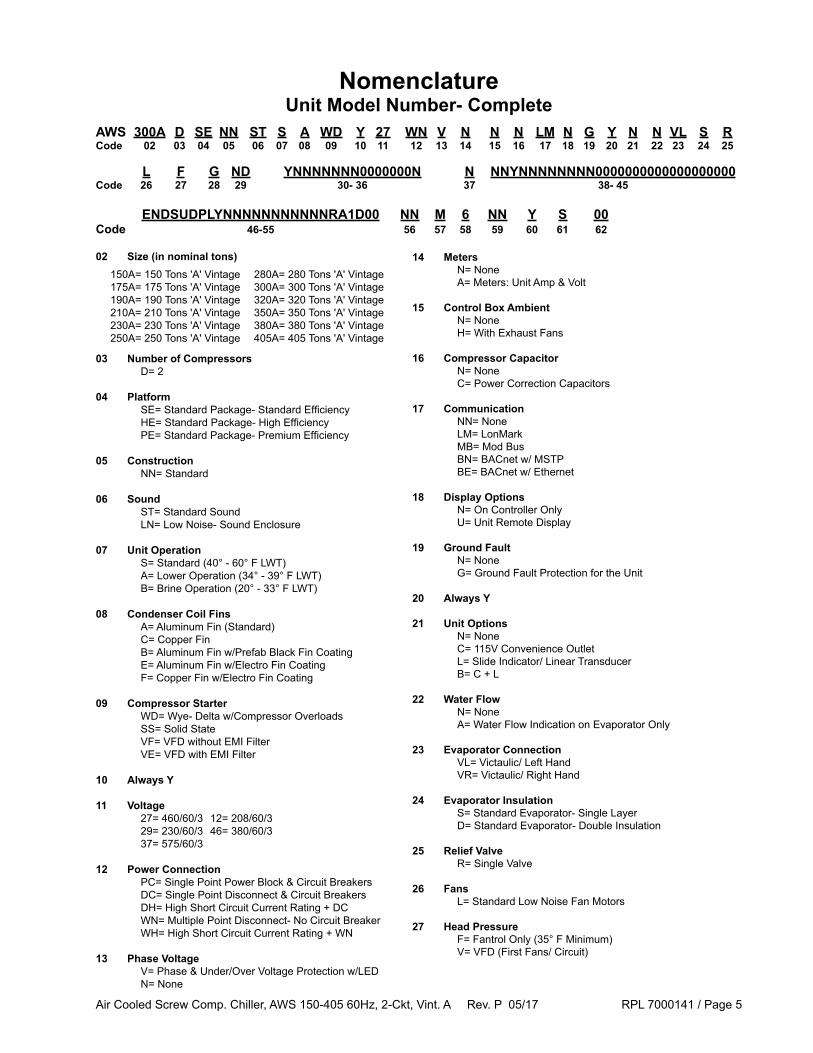
AWS 300A D SE NN ST S A WD Y 27 WN V N N N LM N G Y N N VL S RCode 02 03 04 05 06 07 08 09 10 11 12 13 14 15 16 17 18 19 20 21 22 23 24 25
L F G ND YNNNNNNN0000000N N NNYNNNNNNNN0000000000000000000Code 26 27 28 29 30- 36 37 38- 45
02 Size (in nominal tons)
03 Number of Compressors D= 2
04 Platform SE= Standard Package- Standard Efficiency HE= Standard Package- High Efficiency PE= Standard Package- Premium Efficiency
05 Construction NN= Standard
06 Sound ST= Standard Sound LN= Low Noise- Sound Enclosure
07 Unit Operation S= Standard (40° - 60° F LWT) A= Lower Operation (34° - 39° F LWT) B= Brine Operation (20° - 33° F LWT)
08 Condenser Coil Fins A= Aluminum Fin (Standard) C= Copper Fin B= Aluminum Fin w/Prefab Black Fin Coating E= Aluminum Fin w/Electro Fin Coating F= Copper Fin w/Electro Fin Coating
09 Compressor Starter WD= Wye- Delta w/Compressor Overloads SS= Solid State VF= VFD without EMI Filter VE= VFD with EMI Filter
10 Always Y
11 Voltage 27= 460/60/3 12= 208/60/3 29= 230/60/3 46= 380/60/3 37= 575/60/3
12 Power Connection PC= Single Point Power Block & Circuit Breakers DC= Single Point Disconnect & Circuit Breakers DH= High Short Circuit Current Rating + DC WN= Multiple Point Disconnect- No Circuit Breaker WH= High Short Circuit Current Rating + WN
13 Phase Voltage V= Phase & Under/Over Voltage Protection w/LED N= None
NomenclatureUnit Model Number- Complete
ENDSUDPLYNNNNNNNNNNNRA1D00 NN M 6 NN Y S 00Code 46-55 56 57 58 59 60 61 62
14 Meters N= None A= Meters: Unit Amp & Volt
15 Control Box Ambient N= None H= With Exhaust Fans
16 Compressor Capacitor N= None C= Power Correction Capacitors
17 Communication NN= None LM= LonMark MB= Mod Bus BN= BACnet w/ MSTP BE= BACnet w/ Ethernet
18 Display Options N= On Controller Only U= Unit Remote Display
19 Ground Fault N= None G= Ground Fault Protection for the Unit
20 Always Y
21 Unit Options N= None C= 115V Convenience Outlet L= Slide Indicator/ Linear Transducer B= C + L
22 Water Flow N= None A= Water Flow Indication on Evaporator Only
23 Evaporator Connection VL= Victaulic/ Left Hand VR= Victaulic/ Right Hand
24 Evaporator Insulation S= Standard Evaporator- Single Layer D= Standard Evaporator- Double Insulation
25 Relief Valve R= Single Valve
26 Fans L= Standard Low Noise Fan Motors
27 Head Pressure F= Fantrol Only (35° F Minimum) V= VFD (First Fans/ Circuit)
150A= 150 Tons 'A' Vintage 280A= 280 Tons 'A' Vintage175A= 175 Tons 'A' Vintage 300A= 300 Tons 'A' Vintage190A= 190 Tons 'A' Vintage 320A= 320 Tons 'A' Vintage 210A= 210 Tons 'A' Vintage 350A= 350 Tons 'A' Vintage230A= 230 Tons 'A' Vintage 380A= 380 Tons 'A' Vintage250A= 250 Tons 'A' Vintage 405A= 405 Tons 'A' Vintage
Air Cooled Screw Comp. Chiller, AWS 150-405 60Hz, 2-Ckt, Vint. A Rev. P 05/17 RPL 7000141 / Page 6
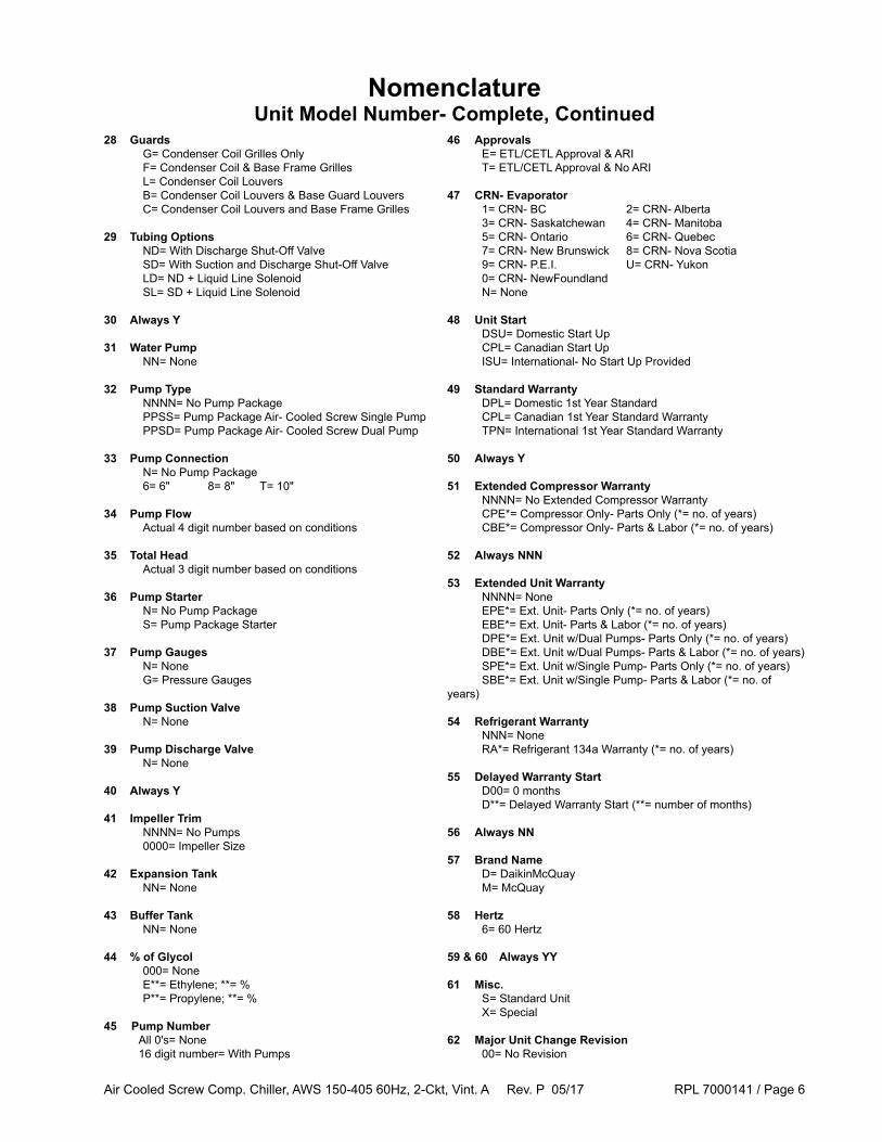
28 Guards G= Condenser Coil Grilles Only F= Condenser Coil & Base Frame Grilles L= Condenser Coil Louvers B= Condenser Coil Louvers & Base Guard Louvers C= Condenser Coil Louvers and Base Frame Grilles
29 Tubing Options ND= With Discharge Shut-Off Valve SD= With Suction and Discharge Shut-Off Valve LD= ND + Liquid Line Solenoid SL= SD + Liquid Line Solenoid
30 Always Y
31 Water Pump NN= None
32 Pump Type NNNN= No Pump Package PPSS= Pump Package Air- Cooled Screw Single Pump PPSD= Pump Package Air- Cooled Screw Dual Pump
33 Pump Connection N= No Pump Package 6= 6" 8= 8" T= 10"
34 Pump Flow Actual 4 digit number based on conditions
35 Total Head Actual 3 digit number based on conditions
36 Pump Starter N= No Pump Package S= Pump Package Starter
37 Pump Gauges N= None G= Pressure Gauges
38 Pump Suction Valve N= None
39 Pump Discharge Valve N= None
40 Always Y
41 Impeller Trim NNNN= No Pumps 0000= Impeller Size
42 Expansion Tank NN= None
43 Buffer Tank NN= None
44 % of Glycol 000= None E**= Ethylene; **= % P**= Propylene; **= %
45 Pump Number All 0's= None 16 digit number= With Pumps
NomenclatureUnit Model Number- Complete, Continued
46 Approvals E= ETL/CETL Approval & ARI T= ETL/CETL Approval & No ARI
47 CRN- Evaporator 1= CRN- BC 2= CRN- Alberta 3= CRN- Saskatchewan 4= CRN- Manitoba 5= CRN- Ontario 6= CRN- Quebec 7= CRN- New Brunswick 8= CRN- Nova Scotia 9= CRN- P.E.I. U= CRN- Yukon 0= CRN- NewFoundland N= None
48 Unit Start DSU= Domestic Start Up CPL= Canadian Start Up ISU= International- No Start Up Provided
49 Standard Warranty DPL= Domestic 1st Year Standard CPL= Canadian 1st Year Standard Warranty TPN= International 1st Year Standard Warranty
50 Always Y
51 Extended Compressor Warranty NNNN= No Extended Compressor Warranty CPE*= Compressor Only- Parts Only (*= no. of years) CBE*= Compressor Only- Parts & Labor (*= no. of years)
52 Always NNN
53 Extended Unit Warranty NNNN= None EPE*= Ext. Unit- Parts Only (*= no. of years) EBE*= Ext. Unit- Parts & Labor (*= no. of years) DPE*= Ext. Unit w/Dual Pumps- Parts Only (*= no. of years) DBE*= Ext. Unit w/Dual Pumps- Parts & Labor (*= no. of years) SPE*= Ext. Unit w/Single Pump- Parts Only (*= no. of years) SBE*= Ext. Unit w/Single Pump- Parts & Labor (*= no. of years)
54 Refrigerant Warranty NNN= None RA*= Refrigerant 134a Warranty (*= no. of years)
55 Delayed Warranty Start D00= 0 months D**= Delayed Warranty Start (**= number of months)
56 Always NN
57 Brand Name D= DaikinMcQuay M= McQuay
58 Hertz 6= 60 Hertz
59 & 60 Always YY
61 Misc. S= Standard Unit X= Special
62 Major Unit Change Revision 00= No Revision
Air Cooled Screw Comp. Chiller, AWS 150-405 60Hz, 2-Ckt, Vint. A Rev. P 05/17 RPL 7000141 / Page 7
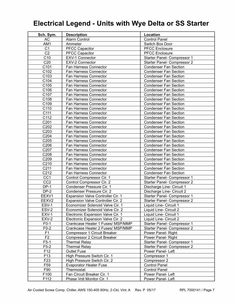
Electrical Legend - Units with Wye Delta or SS Starter Sch. Sym. Description Location AC Alarm Control Control Panel AM1 Ammeter Switch Box Door C1 PFCC Capacitor PFCC Enclosure C2 PFCC Capacitor PFCC Enclosure C10 EXV-1 Connector Starter Panel- Compressor 1 C20 EXV-2 Connector Starter Panel- Compressor 2 C101 Fan Harness Connector Condenser Fan Section C102 Fan Harness Connector Condenser Fan Section C103 Fan Harness Connector Condenser Fan Section C104 Fan Harness Connector Condenser Fan Section C105 Fan Harness Connector Condenser Fan Section C106 Fan Harness Connector Condenser Fan Section C107 Fan Harness Connector Condenser Fan Section C108 Fan Harness Connector Condenser Fan Section C109 Fan Harness Connector Condenser Fan Section C110 Fan Harness Connector Condenser Fan Section C111 Fan Harness Connector Condenser Fan Section C112 Fan Harness Connector Condenser Fan Section C201 Fan Harness Connector Condenser Fan Section C202 Fan Harness Connector Condenser Fan Section C203 Fan Harness Connector Condenser Fan Section C204 Fan Harness Connector Condenser Fan Section C205 Fan Harness Connector Condenser Fan Section C206 Fan Harness Connector Condenser Fan Section C207 Fan Harness Connector Condenser Fan Section C208 Fan Harness Connector Condenser Fan Section C209 Fan Harness Connector Condenser Fan Section C210 Fan Harness Connector Condenser Fan Section C211 Fan Harness Connector Condenser Fan Section C212 Fan Harness Connector Condenser Fan Section CC1 Control Compressor Cir. 1 Starter Panel- Compressor 1 CC2 Control Compressor Cir. 2 Starter Panel- Compressor 2 DP-1 Condenser Pressure Cir. 1 Discharge Line- Circuit 1 DP-2 Condenser Pressure Cir. 2 Discharge Line- Circuit 2 EEXV1 Expansion Valve Controller Cir. 1 Starter Panel- Compressor 1 EEXV2 Expansion Valve Controller Cir. 2 Starter Panel- Compressor 2 ESV-1 Economizer Solenoid Valve Cir. 1 Liquid Line- Circuit 1 ESV-2 Economizer Solenoid Valve Cir. 2 Liquid Line- Circuit 2 EXV-1 Electronic Expansion Valve Cir. 1 Liquid Line- Circuit 1 EXV-2 Electronic Expansion Valve Cir. 2 Liquid Line- Circuit 2 F0-1 Crankcase Heater 1 Fuses/ MSP/MMP Starter Panel- Compressor 1 F0-2 Crankcase Heater 2 Fuses/ MSP/MMP Starter Panel- Compressor 2 F1 Compressor 1 Circuit Breaker Power Panel- Right F2 Compressor 2 Circuit Breaker Power Panel- Right F5-1 Thermal Relay Starter Panel- Compressor 1 F5-2 Thermal Relay Starter Panel- Compressor 2 F12 Outlet Fuse Power Panel- Left F13 High Pressure Switch Cir. 1 Compressor 1 F23 High Pressure Switch Cir. 2 Compressor 2 F59 Evaporator Heater Fuse Control Panel F90 Thermostat Control Panel F100 Fan Circuit Breaker Cir. 1 Power Panel- Left F112 Phase Volt Monitor Cir. 1 Power Panel- Left

Air Cooled Screw Comp. Chiller, AWS 150-405 60Hz, 2-Ckt, Vint. A Rev. P 05/17 RPL 7000141 / Page 8
Sch. Sym. Description Location F116 Evaporator Flow Switch Evaporator Outlet F120 Transformer T1 Protection Power Panel- Left F130 Phase Volt Monitor Fuse Cir. 1 Power Panel- Left F200 Fan Circuit Breaker 2 Power Panel- Left F212 Phase Voltage Monitor Cir. 2 Power Panel- Left F230 Phase Volt Monitor Fuse Cir. 2 Power Panel- Left FC Fans Control Control Panel FTB107 Fan Terminal Block Cir. 1 Power Panel- Left FTB110 Fan Terminal Block Cir. 1 Power Panel- Left FTB207 Fan Terminal Block Cir. 2 Power Panel- Left FTB210 Fan Terminal Block Cir. 2 Power Panel- Left FU1 PFCC Fuse PFCC Enclosure FU2 PFCC Fuse PFCC Enclosure GFR1 Ground Fault Relay Cir. 1 Power Panel- Left GFR2 Ground Fault Relay Cir. 2 Power Panel- Left K11 Emergency Stop Contactor Control Panel K16 Fan Stage 1 Power Panel- Left K26 Fan Stage 2 Power Panel- Left K2B-1 Contactor Starter Panel- Compressor 1 K2B-2 Contactor Starter Panel- Compressor 2 KLJ-1 Liquid Injection Relay 1 Starter Panel- Compressor 1 KLJ-2 Liquid Injection Relay 2 Starter Panel- Compressor 2 KM1-1 Compressor Contactor Starter Panel- Compressor 1 KM1-2 Compressor Contactor Starter Panel- Compressor 1 KM1-3 Compressor Contactor Starter Panel- Compressor 1 KM2-1 Compressor Contactor Starter Panel- Compressor 2 KM2-2 Compressor Contactor Starter Panel- Compressor 2 KM2-3 Compressor Contactor Starter Panel- Compressor 2 KM10-1 Contactor Starter Panel- Compressor 1 KM10-2 Contactor Starter Panel- Compressor 2 KM101 Fan Motor Contactor Power Panel- Left KM102 Fan Motor Contactor Power Panel- Left KM103 Fan Motor Contactor Power Panel- Left KM105 Fan Motor Contactor Power Panel- Left KM107 Fan Motor Contactor Power Panel- Left KM110 Fan Motor Contactor Power Panel- Left KM201 Fan Motor Contactor Power Panel- Left KM202 Fan Motor Contactor Power Panel- Left KM203 Fan Motor Contactor Power Panel- Left KM205 Fan Motor Contactor Power Panel- Left KM207 Fan Motor Contactor Power Panel- Left KM210 Fan Motor Contactor Power Panel- Left KT13 Time Delay Relay 1 Starter Panel- Compressor 1 KT23 Time Delay Relay 2 Starter Panel- Compressor 2 KT-1 Auxilliary Relay Cir. 1 Starter Panel- Compressor 1 KT-2 Aux. Relay Cir. 2 Starter Panel- Compressor 2 KT1-1 Delay Relay Starter Panel- Compressor 1 KT1-2 Delay Relay Starter Panel- Compressor 2 LJV-1 Liquid Injection Solenoid Cir. 1 Liquid Line/Starter Panel 1 LJV-2 Liquid Injection Solenoid Cir. 2 Liquid Line/Starter Panel 2 LP1 Low Pressure Switch 1 Compressor 1 LP2 Low Pressure Switch 2 Compressor 2 LR1 Line Reactor Cir. 1 Power Panel- Left
Electrical Legend - Units with Wye Delta or SS Starter
Air Cooled Screw Comp. Chiller, AWS 150-405 60Hz, 2-Ckt, Vint. A Rev. P 05/17 RPL 7000141 / Page 9
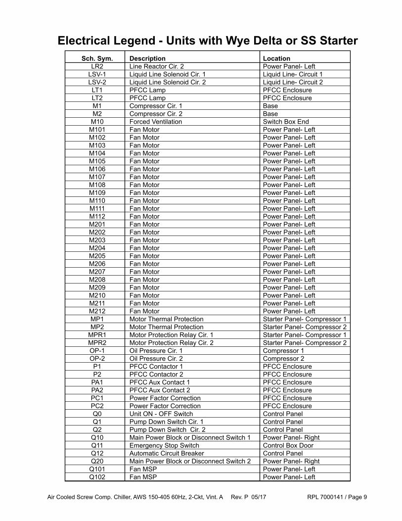
Sch. Sym. Description Location LR2 Line Reactor Cir. 2 Power Panel- Left LSV-1 Liquid Line Solenoid Cir. 1 Liquid Line- Circuit 1 LSV-2 Liquid Line Solenoid Cir. 2 Liquid Line- Circuit 2 LT1 PFCC Lamp PFCC Enclosure LT2 PFCC Lamp PFCC Enclosure M1 Compressor Cir. 1 Base M2 Compressor Cir. 2 Base M10 Forced Ventilation Switch Box End M101 Fan Motor Power Panel- Left M102 Fan Motor Power Panel- Left M103 Fan Motor Power Panel- Left M104 Fan Motor Power Panel- Left M105 Fan Motor Power Panel- Left M106 Fan Motor Power Panel- Left M107 Fan Motor Power Panel- Left M108 Fan Motor Power Panel- Left M109 Fan Motor Power Panel- Left M110 Fan Motor Power Panel- Left M111 Fan Motor Power Panel- Left M112 Fan Motor Power Panel- Left M201 Fan Motor Power Panel- Left M202 Fan Motor Power Panel- Left M203 Fan Motor Power Panel- Left M204 Fan Motor Power Panel- Left M205 Fan Motor Power Panel- Left M206 Fan Motor Power Panel- Left M207 Fan Motor Power Panel- Left M208 Fan Motor Power Panel- Left M209 Fan Motor Power Panel- Left M210 Fan Motor Power Panel- Left M211 Fan Motor Power Panel- Left M212 Fan Motor Power Panel- Left MP1 Motor Thermal Protection Starter Panel- Compressor 1 MP2 Motor Thermal Protection Starter Panel- Compressor 2 MPR1 Motor Protection Relay Cir. 1 Starter Panel- Compressor 1 MPR2 Motor Protection Relay Cir. 2 Starter Panel- Compressor 2 OP-1 Oil Pressure Cir. 1 Compressor 1 OP-2 Oil Pressure Cir. 2 Compressor 2 P1 PFCC Contactor 1 PFCC Enclosure P2 PFCC Contactor 2 PFCC Enclosure PA1 PFCC Aux Contact 1 PFCC Enclosure PA2 PFCC Aux Contact 2 PFCC Enclosure PC1 Power Factor Correction PFCC Enclosure PC2 Power Factor Correction PFCC Enclosure Q0 Unit ON - OFF Switch Control Panel Q1 Pump Down Switch Cir. 1 Control Panel Q2 Pump Down Switch Cir. 2 Control Panel Q10 Main Power Block or Disconnect Switch 1 Power Panel- Right Q11 Emergency Stop Switch Control Box Door Q12 Automatic Circuit Breaker Control Panel Q20 Main Power Block or Disconnect Switch 2 Power Panel- Right Q101 Fan MSP Power Panel- Left Q102 Fan MSP Power Panel- Left
Electrical Legend - Units with Wye Delta or SS Starter
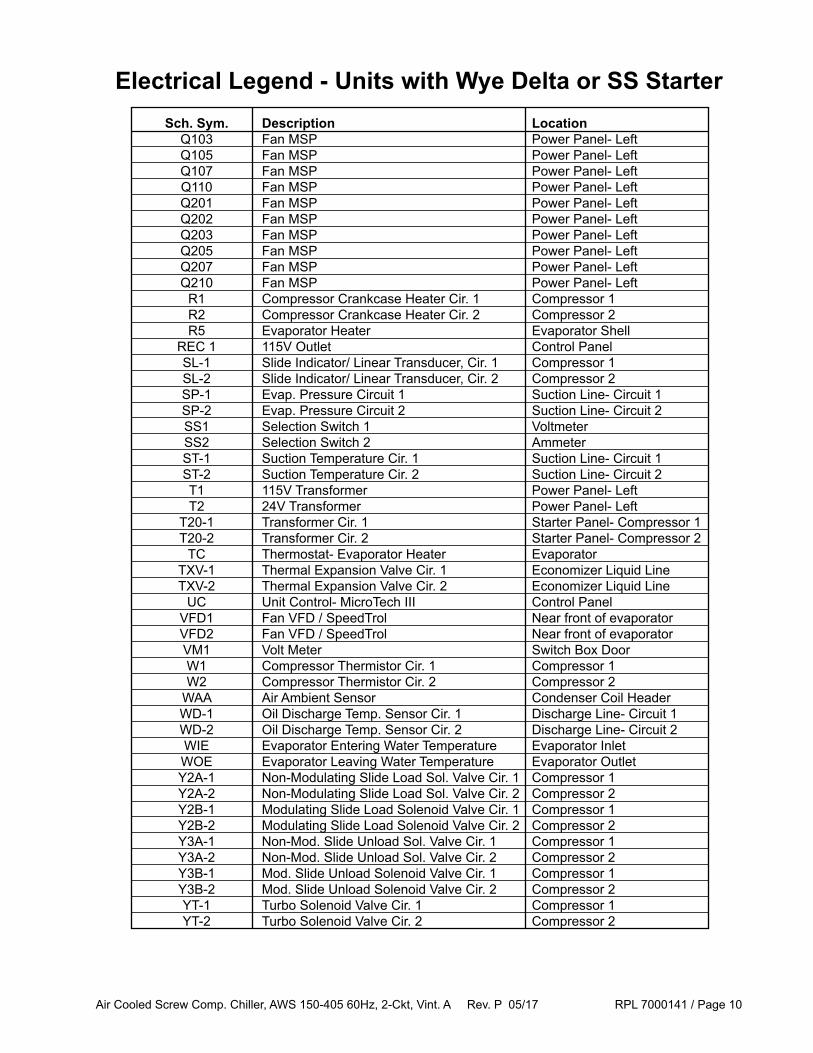
Air Cooled Screw Comp. Chiller, AWS 150-405 60Hz, 2-Ckt, Vint. A Rev. P 05/17 RPL 7000141 / Page 10
Sch. Sym. Description Location Q103 Fan MSP Power Panel- Left Q105 Fan MSP Power Panel- Left Q107 Fan MSP Power Panel- Left Q110 Fan MSP Power Panel- Left Q201 Fan MSP Power Panel- Left Q202 Fan MSP Power Panel- Left Q203 Fan MSP Power Panel- Left Q205 Fan MSP Power Panel- Left Q207 Fan MSP Power Panel- Left Q210 Fan MSP Power Panel- Left R1 Compressor Crankcase Heater Cir. 1 Compressor 1 R2 Compressor Crankcase Heater Cir. 2 Compressor 2 R5 Evaporator Heater Evaporator Shell REC 1 115V Outlet Control Panel SL-1 Slide Indicator/ Linear Transducer, Cir. 1 Compressor 1 SL-2 Slide Indicator/ Linear Transducer, Cir. 2 Compressor 2 SP-1 Evap. Pressure Circuit 1 Suction Line- Circuit 1 SP-2 Evap. Pressure Circuit 2 Suction Line- Circuit 2 SS1 Selection Switch 1 Voltmeter SS2 Selection Switch 2 Ammeter ST-1 Suction Temperature Cir. 1 Suction Line- Circuit 1 ST-2 Suction Temperature Cir. 2 Suction Line- Circuit 2 T1 115V Transformer Power Panel- Left T2 24V Transformer Power Panel- Left T20-1 Transformer Cir. 1 Starter Panel- Compressor 1 T20-2 Transformer Cir. 2 Starter Panel- Compressor 2 TC Thermostat- Evaporator Heater Evaporator TXV-1 Thermal Expansion Valve Cir. 1 Economizer Liquid Line TXV-2 Thermal Expansion Valve Cir. 2 Economizer Liquid Line UC Unit Control- MicroTech III Control Panel VFD1 Fan VFD / SpeedTrol Near front of evaporator VFD2 Fan VFD / SpeedTrol Near front of evaporator VM1 Volt Meter Switch Box Door W1 Compressor Thermistor Cir. 1 Compressor 1 W2 Compressor Thermistor Cir. 2 Compressor 2 WAA Air Ambient Sensor Condenser Coil Header WD-1 Oil Discharge Temp. Sensor Cir. 1 Discharge Line- Circuit 1 WD-2 Oil Discharge Temp. Sensor Cir. 2 Discharge Line- Circuit 2 WIE Evaporator Entering Water Temperature Evaporator Inlet WOE Evaporator Leaving Water Temperature Evaporator Outlet Y2A-1 Non-Modulating Slide Load Sol. Valve Cir. 1 Compressor 1 Y2A-2 Non-Modulating Slide Load Sol. Valve Cir. 2 Compressor 2 Y2B-1 Modulating Slide Load Solenoid Valve Cir. 1 Compressor 1 Y2B-2 Modulating Slide Load Solenoid Valve Cir. 2 Compressor 2 Y3A-1 Non-Mod. Slide Unload Sol. Valve Cir. 1 Compressor 1 Y3A-2 Non-Mod. Slide Unload Sol. Valve Cir. 2 Compressor 2 Y3B-1 Mod. Slide Unload Solenoid Valve Cir. 1 Compressor 1 Y3B-2 Mod. Slide Unload Solenoid Valve Cir. 2 Compressor 2 YT-1 Turbo Solenoid Valve Cir. 1 Compressor 1 YT-2 Turbo Solenoid Valve Cir. 2 Compressor 2
Electrical Legend - Units with Wye Delta or SS Starter

Air Cooled Screw Comp. Chiller, AWS 150-405 60Hz, 2-Ckt, Vint. A Rev. P 05/17 RPL 7000141 / Page 11
Electrical Legend - Units with VFD Starter Sch. Sym. Description Location AC Alarm Control Control Side AM1 Ammeter Control Box Door C10 EXV-1 Connector Outside Back of Control Side C20 EXV-2 Connector Outside Back of Control Side C101 Fan Harness Connector Condenser Fan Section C102 Fan Harness Connector Condenser Fan Section C103 Fan Harness Connector Condenser Fan Section C104 Fan Harness Connector Condenser Fan Section C105 Fan Harness Connector Condenser Fan Section C106 Fan Harness Connector Condenser Fan Section C107 Fan Harness Connector Condenser Fan Section C108 Fan Harness Connector Condenser Fan Section C109 Fan Harness Connector Condenser Fan Section C110 Fan Harness Connector Condenser Fan Section C111 Fan Harness Connector Condenser Fan Section C112 Fan Harness Connector Condenser Fan Section C201 Fan Harness Connector Condenser Fan Section C202 Fan Harness Connector Condenser Fan Section C203 Fan Harness Connector Condenser Fan Section C204 Fan Harness Connector Condenser Fan Section C205 Fan Harness Connector Condenser Fan Section C206 Fan Harness Connector Condenser Fan Section C207 Fan Harness Connector Condenser Fan Section C208 Fan Harness Connector Condenser Fan Section C209 Fan Harness Connector Condenser Fan Section C210 Fan Harness Connector Condenser Fan Section C211 Fan Harness Connector Condenser Fan Section C212 Fan Harness Connector Condenser Fan Section CC1 Control Compressor Cir. 1 Control Side CC2 Control Compressor Cir. 2 Control Side DP-1 Condenser Pressure Cir. 1 Discharge Line- Circuit 1 DP-2 Condenser Pressure Cir. 2 Discharge Line- Circuit 2 EEXV1 Expansion Valve Controller Cir. 1 Control Side EEXV2 Expansion Valve Controller Cir. 2 Control Side EMI-1 Electromagnetic Interference Filter 1 Power Side EMI-2 Electromagnetic Interference Filter 2 Power Side ESV-1 Economizer Solenoid Valve Cir. 1 Liquid Line- Circuit 1 ESV-2 Economizer Solenoid Valve Cir. 2 Liquid Line- Circuit 2 EXV-1 Electronic Expansion Valve Cir. 1 Liquid Line- Circuit 1 EXV-2 Electronic Expansion Valve Cir. 2 Liquid Line- Circuit 2 F0-1 Crankcase Heater 1 Fuses/ MSP/MMP Power Side F0-2 Crankcase Heater 2 Fuses/ MSP/MMP Power Side F1 Compressor 1 Circuit Breaker Power Side F2 Compressor 2 Circuit Breaker Power Side F10 Exhaust Fan Fuse Control Side F11 Unit Controller Fuse Control Side F12 Outlet Fuse Control Side F13 High Pressure Switch Cir. 1 Compressor 1 F23 High Pressure Switch Cir. 2 Compressor 2 F59 Evaporator Heater Fuse Control Side F90 Thermostat Control Side F100 Fan Circuit Breaker Cir. 1 Control Side F116 Evaporator Flow Switch Evaporator Outlet

Air Cooled Screw Comp. Chiller, AWS 150-405 60Hz, 2-Ckt, Vint. A Rev. P 05/17 RPL 7000141 / Page 12
Electrical Legend - Units with VFD Starter Sch. Sym. Description Location F120 Transformer T1 Protection Power Side F130 Phase Volt Monitor Fuse Control Side F200 Fan Circuit Breaker 2 Control Side FC Fans Control Control Side FTB107 Fan Terminal Block Cir. 1 Control Side FTB110 Fan Terminal Block Cir. 1 Control Side FTB207 Fan Terminal Block Cir. 2 Control Side FTB210 Fan Terminal Block Cir. 2 Control Side GFR1 Ground Fault Relay Cir. 1 Control Side GFR2 Ground Fault Relay Cir. 2 Control Side JFU1 HSCR Fuse 1 Control Side JFU2 HSCR Fuse 2 Control Side K1 Compressor VFD Run Relay 1 Power Side K2 Compressor VFD Run Relay 2 Power Side K11 Emergency Stop Contactor Control Side K13 Mechanical Hi Pressure Relay & Contactor Control Side K16 Fan Stage Cir. 1 Control Side K23 Mechanical Hi Pressure Relay & Contactor Control Side K26 Fan Stage Cir. 2 Control Side KLJ-1 Liquid Injection Relay 1 Control Side KLJ-2 Liquid Injection Relay 2 Control Side KM101 Fan Motor Contactor Control Side KM102 Fan Motor Contactor Control Side KM103 Fan Motor Contactor Control Side KM105 Fan Motor Contactor Control Side KM107 Fan Motor Contactor Control Side KM110 Fan Motor Contactor Control Side KM201 Fan Motor Contactor Control Side KM202 Fan Motor Contactor Control Side KM203 Fan Motor Contactor Control Side KM205 Fan Motor Contactor Control Side KM207 Fan Motor Contactor Control Side KM210 Fan Motor Contactor Control Side LJV-1 Liquid Injection Solenoid Cir. 1 Liquid Injection Line 1 LJV-2 Liquid Injection Solenoid Cir. 2 Liquid Injection Line 2 LP1 Low Pressure Switch 1 Compressor 1 LP2 Low Pressure Switch 2 Compressor 2 LR1 Line Reactor Cir. 1 Control Side LR2 Line Reactor Cir. 2 Control Side LSV-1 Liquid Line Solenoid Cir. 1 Liquid Line- Circuit 1 LSV-2 Liquid Line Solenoid Cir. 2 Liquid Line- Circuit 2 M1 Compressor Cir. 1 Base M2 Compressor Cir. 2 Base M10 Forced Ventilation Outside Wall of Power Side M11 Intake Fan Outside Wall of Control Side M12 Exhaust Fan Control Box Left Door M101 Fan Motor Condenser Fan Section M102 Fan Motor Condenser Fan Section M103 Fan Motor Condenser Fan Section M104 Fan Motor Condenser Fan Section M105 Fan Motor Condenser Fan Section M106 Fan Motor Condenser Fan Section M107 Fan Motor Condenser Fan Section
Air Cooled Screw Comp. Chiller, AWS 150-405 60Hz, 2-Ckt, Vint. A Rev. P 05/17 RPL 7000141 / Page 13
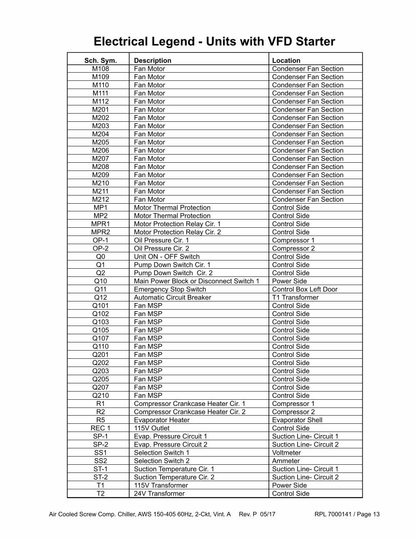
Electrical Legend - Units with VFD Starter Sch. Sym. Description Location M108 Fan Motor Condenser Fan Section M109 Fan Motor Condenser Fan Section M110 Fan Motor Condenser Fan Section M111 Fan Motor Condenser Fan Section M112 Fan Motor Condenser Fan Section M201 Fan Motor Condenser Fan Section M202 Fan Motor Condenser Fan Section M203 Fan Motor Condenser Fan Section M204 Fan Motor Condenser Fan Section M205 Fan Motor Condenser Fan Section M206 Fan Motor Condenser Fan Section M207 Fan Motor Condenser Fan Section M208 Fan Motor Condenser Fan Section M209 Fan Motor Condenser Fan Section M210 Fan Motor Condenser Fan Section M211 Fan Motor Condenser Fan Section M212 Fan Motor Condenser Fan Section MP1 Motor Thermal Protection Control Side MP2 Motor Thermal Protection Control Side MPR1 Motor Protection Relay Cir. 1 Control Side MPR2 Motor Protection Relay Cir. 2 Control Side OP-1 Oil Pressure Cir. 1 Compressor 1 OP-2 Oil Pressure Cir. 2 Compressor 2 Q0 Unit ON - OFF Switch Control Side Q1 Pump Down Switch Cir. 1 Control Side Q2 Pump Down Switch Cir. 2 Control Side Q10 Main Power Block or Disconnect Switch 1 Power Side Q11 Emergency Stop Switch Control Box Left Door Q12 Automatic Circuit Breaker T1 Transformer Q101 Fan MSP Control Side Q102 Fan MSP Control Side Q103 Fan MSP Control Side Q105 Fan MSP Control Side Q107 Fan MSP Control Side Q110 Fan MSP Control Side Q201 Fan MSP Control Side Q202 Fan MSP Control Side Q203 Fan MSP Control Side Q205 Fan MSP Control Side Q207 Fan MSP Control Side Q210 Fan MSP Control Side R1 Compressor Crankcase Heater Cir. 1 Compressor 1 R2 Compressor Crankcase Heater Cir. 2 Compressor 2 R5 Evaporator Heater Evaporator Shell REC 1 115V Outlet Control Side SP-1 Evap. Pressure Circuit 1 Suction Line- Circuit 1 SP-2 Evap. Pressure Circuit 2 Suction Line- Circuit 2 SS1 Selection Switch 1 Voltmeter SS2 Selection Switch 2 Ammeter ST-1 Suction Temperature Cir. 1 Suction Line- Circuit 1 ST-2 Suction Temperature Cir. 2 Suction Line- Circuit 2 T1 115V Transformer Power Side T2 24V Transformer Control Side

Air Cooled Screw Comp. Chiller, AWS 150-405 60Hz, 2-Ckt, Vint. A Rev. P 05/17 RPL 7000141 / Page 14
Electrical Legend - Units with VFD Starter Sch. Sym. Description Location T20-1 Transformer Cir. 1 Control Side T20-2 Transformer Cir. 2 Control Side TC Thermostat- Evaporator Heater Evaporator UC Unit Control- MicroTech III Control Side VFD1 Fan VFD / SpeedTrol Control Side Left Wall VFD2 Fan VFD / SpeedTrol Control Side Left Wall VFD-1 Compressor VFD 1 Power Side VFD-2 Compressor VFD 2 Power Side VFU1 Compressor VFD Fuse 1 Power Side VFU2 Compressor VFD Fuse 2 Power Side VM1 Volt Meter Switch Box Door W1 Compressor Thermistor Cir. 1 Compressor 1 W2 Compressor Thermistor Cir. 2 Compressor 2 WAA Air Ambient Sensor Condenser Coil Header WD-1 Oil Discharge Temp. Sensor Cir. 1 Discharge Line- Circuit 1 WD-2 Oil Discharge Temp. Sensor Cir. 2 Discharge Line- Circuit 2 WIE Evaporator Entering Water Temperature Evaporator Inlet WOE Evaporator Leaving Water Temperature Evaporator Outlet

Air Cooled Screw Comp. Chiller, AWS 150-405 60Hz, 2-Ckt, Vint. A Rev. P 05/17 RPL 7000141 / Page 15
Unit Layout(Unit Size 300ADS Shown)
10
1
8
2
Ref. No. Description Location 1 Compressors Refrigeration Section 2 Tubing (suction, discharge, liquid injection) Refrigeration Section 3 Liquid Line and Economizer Refrigeration Section 7 Evaporator Refrigeration Section 8 Condenser Coil Refrigeration Section 9 Condenser Fans Refrigeration Section 10 Unit Switch Box/Control Panel * Controls Section 11 Compressor Starter Panel (not on units with VFD Starters) Controls Section 12 Compressor Terminal Box Controls Section
9
7
9 9 9 99 9 9
113
12
* Control Panel for units with Wye-Delta or Solid State Starters shown. Larger Panel used on units with VFD Starters.

Air Cooled Screw Comp. Chiller, AWS 150-405 60Hz, 2-Ckt, Vint. A Rev. P 05/17 RPL 7000141 / Page 16
Unit Size Starter Std Eff. High Eff Premium Eff (Code 9) 150 VE or VF A -- -- 175 any A -- -- 190 WD or SS A -- -- 190 VE or VF C -- -- 210 any C A A 230 any C A A 250 any B C C 280 any B C C 300 any E B B 320 any E B B 350 any D E E 380 any -- E -- 405 any -- D --
Unit Size Starter Std Eff. High Eff Premium Eff (Code 9) 150 VE or VF A -- -- 175 WD or SS A -- -- 175 VE or VF C -- -- 190 any C -- -- 210 any C A A 230 any B C C 250 any B C C 280 any E B B 300 any E B B 320 any D E E 350 any D E E 380 any -- D -- 405 any -- D --
Compressor, Circuit 1
Refrigeration SectionCompressor Charts
Compressor, Circuit 2
See next page for Compressor part numbers.
Standard Efficiency: Code 4 = S*High Efficiency: Code 4 = H*
Premium Efficiency: Code 4 = P*
For units built after 8/1/11, contact Daikin Applied for part number identification of Compressors.

Air Cooled Screw Comp. Chiller, AWS 150-405 60Hz, 2-Ckt, Vint. A Rev. P 05/17 RPL 7000141 / Page 17
Compressor A Units built before Sept. 2010 may have the Original or New Compressor A. See diagrams at right to determine which you have. To replace an Original Compressor A, order the New Compressor A plus the corresponding Retrofit Kit.
208V - new 332525070 230V - new 332525075 380V - new (units w/ VFD Starters) 332525180 380V - new (units w/o VFD Starters) 332525080 460V - new (units w/ VFD Starters) 332525160 460V - new (units w/o VFD Starters) 332525060 575V - new 332525065
Retrofit Kit - Circuit 1 332517701 Retrofit Kit - Circuit 2 332517702
Compressor B 208V 332525272 230V 332525277 380V (units w/ VFD Starters) 332525382 380V (units w/o VFD Starters) 332525282 460V (units w/ VFD Starters) 332525362 460V (units w/o VFD Starters) 332525262 575V 332525267
Compressor C 208V 332525271 230V 332525276 380V (units w/ VFD Starters) 332525381 380V (units w/o VFD Starters) 332525281 460V (units w/ VFD Starters) 332525361 460V (units w/o VFD Starters) 332525261 575V 332525266
Compressor D 380V (units w/ VFD Starters) 10000108984 380V (units w/o VFD Starters) 10000102384 460V (units w/ VFD Starters) 10000108964 460V (units w/o VFD Starters) 10000102364 575V 10000102369
Compressor E 380V (units w/ VFD Starters) 10000108983 380V (units w/o VFD Starters) 10000102383 460V (units w/ VFD Starters) 10000108963 460V (units w/o VFD Starters) 10000102363 575V 10000102368
Units with VFD Starters: Code 9 = VE, VF. Units without VFD Starters: Code 9 = WD or SS
Compressor A - New
Oil Filter
Oil Filter
Compressor A - Original
Refrigeration SectionCompressors
See previous page for Compressor Charts.
For units built after 8/1/11, contact Daikin Applied for part number identification of Compressors.

Air Cooled Screw Comp. Chiller, AWS 150-405 60Hz, 2-Ckt, Vint. A Rev. P 05/17 RPL 7000141 / Page 18
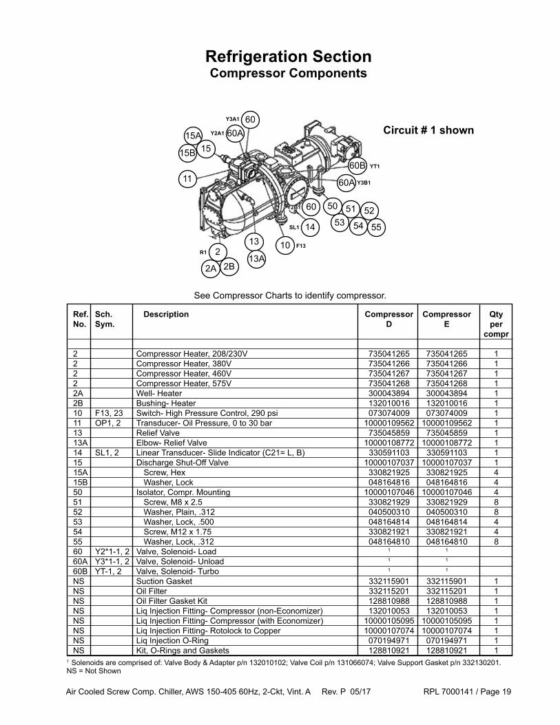
Ref. Sch. Description Compressor Compressor Compressor Qty No. Sym. A B C per compr 2 Compressor Heater, 208-230V 735041265 735041265 735041265 1 2 Compressor Heater, 380V 735041266 735041266 735041266 1 2 Compressor Heater, 460V 735041267 735041267 735041267 1 2 Compressor Heater, 575V 735041268 735041268 735041268 1 2A Well- Heater 300043894 300043894 300043894 1 2B Bushing- Heater 132010016 132010016 132010016 1 10 F13, 23 Switch- High Pressure Control, 290 psi 073074009 073074009 073074009 1 11 OP1, 2 Transducer- Oil Pressure, 0 to 30 bar 10000109562 1000109562 10000109562 1 13 Relief Valve 2 735045859 2 735045859 735045859 1 13A Elbow- Relief Valve 10000108772 10000108772 10000108772 1 14 SL1, 2 Linear Transducer- Slide Indicator (C21= L, B) 330591103 330591103 330591103 1 14A Cable for Linear Transducer (16 ft) 331991702 331991702 331991702 1 14A Cable for Linear Transducer (32 ft) 331991703 331991703 331991703 1 15 Discharge Shut-Off Valve 2 10000107127 2 10000107037 10000107037 1 15A Screw, Hex 330821937 330821925 330821925 4 15B Washer, Lock 048164815 048164816 048164816 4 50 Isolator, Compr. Mounting 10000107142 10000107142 10000107142 4 51 Screw, M8 x 2.5 C101 330821929 330821929 330821929 8 52 Washer, Plain, .312 040500322 040500322 040500322 8 53 Washer, Lock, .500 048164814 048164814 048164814 4 54 Screw, M12 x 1.75 330821921 330821921 330821921 4 55 Washer, Lock, .312 048164810 048164810 048164810 8 60 Y2*1-1, 2 Valve, Solenoid- Load 1 1 1 60A Y3*1-1, 2 Valve, Solenoid- Unload 1 1 1
60B YT-1, 2 Valve, Solenoid- Turbo 1 1 1
NS Suction Gasket 350233902 332115901 332115901 1 NS Oil Filter 332126801 332115201 332115201 1 NS Oil Filter Gasket Kit 128810988 128810988 128810988 1 NS Liq Injection Fitting- Compr (non-Economizer) 132010068 132010053 132010053 1 NS Liq Injection Fitting- Compr (with Economizer) 10000105096 10000105095 10000105095 1 NS Liq Injection Fitting- Rotolock to Copper 10000107074 10000107074 10000107074 1 NS Liq Injection O-Ring 070194921 070194971 070194971 1 NS Kit, O-Rings and Gaskets 128810917 128810919 128810919 1
Refrigeration SectionCompressor Components
1 Solenoids are comprised of: Valve Body & Adapter p/n 132010102; Valve Coil p/n 131066074; Valve Support Gasket p/n 332130201.2 If unit has original Compressor A (see previous page), use: Relief Valve 735045860 and Shut-off Valve 735039803NS = Not Shown
Circuit # 1 shown
10
11
213
14
5150
5352
13A
54
1515A
15B
60A60
60
60B
60A Y3B1
YT1
Y2B1
Y3A1
Y2A1
R1F13
SL1
2A 2BSee Compressor Charts to identify compressor.
55
Air Cooled Screw Comp. Chiller, AWS 150-405 60Hz, 2-Ckt, Vint. A Rev. P 05/17 RPL 7000141 / Page 19
Ref. Sch. Description Compressor Compressor Qty No. Sym. D E per compr
2 Compressor Heater, 208/230V 735041265 735041265 1 2 Compressor Heater, 380V 735041266 735041266 1 2 Compressor Heater, 460V 735041267 735041267 1 2 Compressor Heater, 575V 735041268 735041268 1 2A Well- Heater 300043894 300043894 1 2B Bushing- Heater 132010016 132010016 1 10 F13, 23 Switch- High Pressure Control, 290 psi 073074009 073074009 1 11 OP1, 2 Transducer- Oil Pressure, 0 to 30 bar 10000109562 10000109562 1 13 Relief Valve 735045859 735045859 1 13A Elbow- Relief Valve 10000108772 10000108772 1 14 SL1, 2 Linear Transducer- Slide Indicator (C21= L, B) 330591103 330591103 1 15 Discharge Shut-Off Valve 10000107037 10000107037 1 15A Screw, Hex 330821925 330821925 4 15B Washer, Lock 048164816 048164816 4 50 Isolator, Compr. Mounting 10000107046 10000107046 4 51 Screw, M8 x 2.5 330821929 330821929 8 52 Washer, Plain, .312 040500310 040500310 8 53 Washer, Lock, .500 048164814 048164814 4 54 Screw, M12 x 1.75 330821921 330821921 4 55 Washer, Lock, .312 048164810 048164810 8 60 Y2*1-1, 2 Valve, Solenoid- Load 1 1 60A Y3*1-1, 2 Valve, Solenoid- Unload 1 1
60B YT-1, 2 Valve, Solenoid- Turbo 1 1
NS Suction Gasket 332115901 332115901 1 NS Oil Filter 332115201 332115201 1 NS Oil Filter Gasket Kit 128810988 128810988 1 NS Liq Injection Fitting- Compressor (non-Economizer) 132010053 132010053 1 NS Liq Injection Fitting- Compressor (with Economizer) 10000105095 10000105095 1 NS Liq Injection Fitting- Rotolock to Copper 10000107074 10000107074 1 NS Liq Injection O-Ring 070194971 070194971 1 NS Kit, O-Rings and Gaskets 128810921 128810921 1
Refrigeration SectionCompressor Components
1 Solenoids are comprised of: Valve Body & Adapter p/n 132010102; Valve Coil p/n 131066074; Valve Support Gasket p/n 332130201.NS = Not Shown
Circuit # 1 shown
10
11
213
14
5150
5352
13A
54
1515A
15B
60A60
60
60B
60A Y3B1
YT1
Y2B1
Y3A1
Y2A1
R1F13
SL1
2A 2B
See Compressor Charts to identify compressor.
55
Air Cooled Screw Comp. Chiller, AWS 150-405 60Hz, 2-Ckt, Vint. A Rev. P 05/17 RPL 7000141 / Page 20
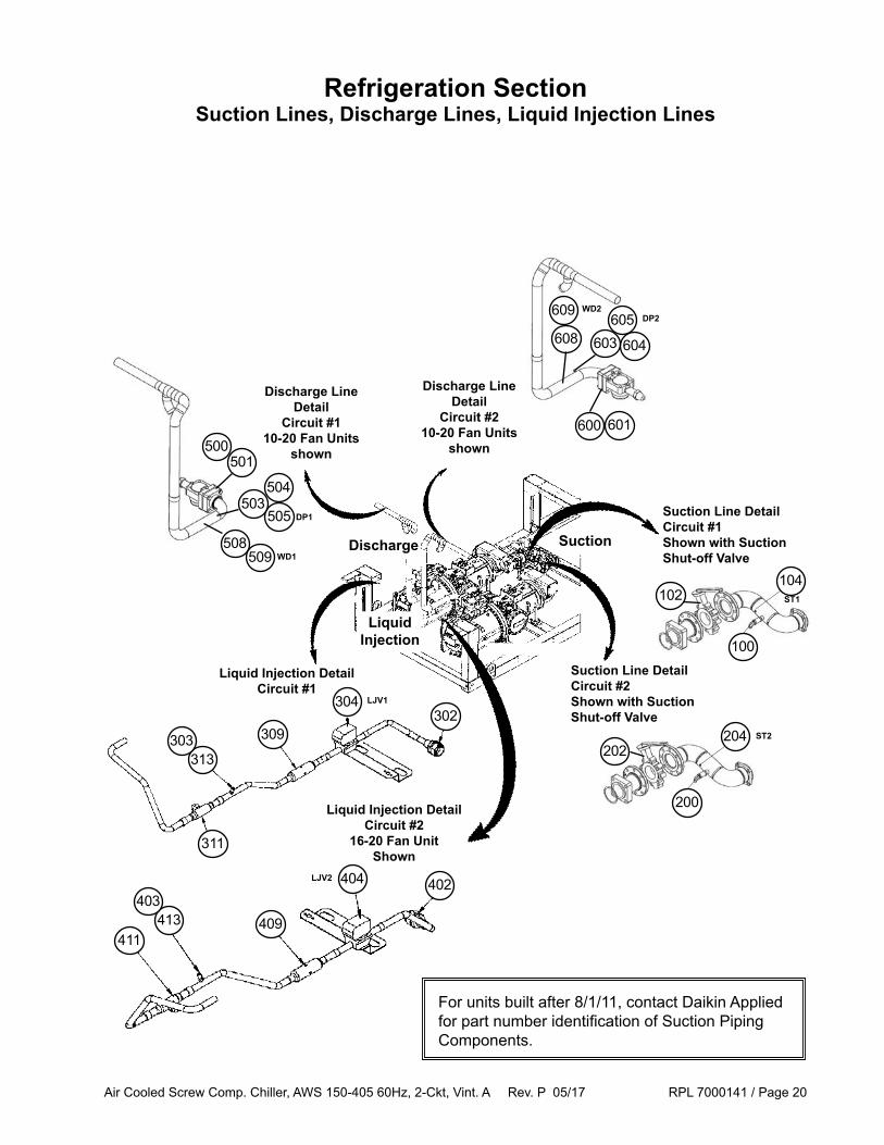
Liquid Injection DetailCircuit #1
Refrigeration SectionSuction Lines, Discharge Lines, Liquid Injection Lines
Suction Line DetailCircuit #1 Shown with SuctionShut-off Valve
Suction Line DetailCircuit #2Shown with SuctionShut-off Valve
311
313
309
304302
303
411413 409
404 402403
Liquid Injection DetailCircuit #2
16-20 Fan UnitShown
Discharge Line Detail
Circuit #1 10-20 Fan Units
shown
508
500501
Discharge Line Detail
Circuit #2 10-20 Fan Units
shown
608605
604603
600 601
505
504503
Suction
LiquidInjection
Discharge509
609DP2
DP1
LJV2
LJV1
WD2
WD1
102
100
104ST1
202
200
204 ST2
For units built after 8/1/11, contact Daikin Applied for part number identification of Suction Piping Components.

Air Cooled Screw Comp. Chiller, AWS 150-405 60Hz, 2-Ckt, Vint. A Rev. P 05/17 RPL 7000141 / Page 21
Refrigeration SectionSuction Lines, Discharge Lines, Liquid Injection
Ref Sch. Part Part No. Sym. Description Number Qty. Suction Line- Circuit #1 100 Valve- Relief 200 PSI 735045852 1 102 Valve- Suction Shutoff see next page 1 104 ST1 Sensor- Suction Temperature, Bent, 30 ft. 332519703 1 Sensor- Suction Temperature, Straight, 30 ft. 193414603 1 N/S SP1 Transducer- Suction -1 to 7 bar 10000109563 1 Suction Line- Circuit #2 200 Valve- Relief 200 PSI 735045852 1 202 Valve- Suction Shutoff see next page 1 204 ST2 Sensor- Suction Temperature, Bent, 30 ft. 332519703 1 Sensor- Suction Temperature, Straight, 30 ft. 193414603 1 N/S SP2 Transducer- Suction Pressure -1 to 7 bar 10000109563 1 Liquid Injection- Circuit #1 302 Fitting- Rotolock 10000107074 1 303 Valve- Schrader 071100801 1 304 LJV1 Valve- Solenoid 120V 331451002 1 309 Strainer 735030506 1 311 Valve- Ball 330286003 1 313 Cap- Valve 032943500 1 Liquid Injection- Circuit #2 402 Fitting- Rotolock 10000107074 1 403 Valve- Schrader 071100801 1 404 LJV2 Valve- Solenoid 120V 331451002 1 409 Strainer 735030506 1 411 Valve- Ball 330286003 1 413 Cap- Valve 032943500 1 Discharge Line- Circuit #1 500 Coupling * 3.13 10000108703 1 501 Kit- Flange * 4.12 735016406 1 NS Gasket- Discharge Shut-Off Valve * 070199144 1 503 Valve- Schrader 071100801 1 504 Core- Valve 026541100 1 505 DP1 Transducer- Discharge Pressure 0 to 30 bar 10000109562 1 508 Tube- Sensor 070228901 1 509 WD1 Sensor- Discharge Temperature, 20 ft. 193414602 1 Discharge Line- Circuit #2 600 Coupling ** 3.13 10000108703 1 601 Kit- Flange ** 4.12 735016406 1 NS Gasket- Discharge Shut-Off Valve ** 070199144 1 603 Valve- Schrader 071100801 1 604 Core- Valve 026541100 1 605 DP2 Transducer- Discharge Pressure 0 to 30 bar 10000109562 1 608 Tube- Sensor 070228901 1 609 WD2 Sensor- Discharge Temperature, 20 ft. 193414602 1
* Circuit 1 - On the following units, use Coupling/Adapter 735049707, Flange Kit 735016404, and Discharge Shut-Off Valve Gasket 070199117: 150ADS, 175ADS, 190ADS, 210ADH, 210ADP, 230ADH, 230ADP.** Circuit 2 - On the following units, use Coupling/Adapter 735049707 and Flange Kit 735016404, and Discharge Shut-Off Valve Gasket 070199117: 150ADS, 175ADS, 210ADH, 210ADP.NS= Not shown
For units built after 8/1/11, contact Daikin Applied for part number identification of Suction Piping Components.

Air Cooled Screw Comp. Chiller, AWS 150-405 60Hz, 2-Ckt, Vint. A Rev. P 05/17 RPL 7000141 / Page 22
Unit Size Standard Eff. High Eff. Premium Eff. 150 073062104 -- -- 175 073062104 -- -- 190 073062104 -- -- 210 073062104 073062104 073062104 230 073062104 073062104 073062104 250 073062104 073062104 See Note below 280 See Note below See Note below See Note below 300 See Note below See Note below See Note below 320 See Note below See Note below See Note below 350 See Note below See Note below See Note below 380 -- See Note below -- 405 -- See Note below --
Ref. 102: Suction Shut Off Valve, Circuit 1
Unit Size Standard Eff. High Eff. Premium Eff. 150 073062104 -- -- 175 073062104 -- -- 190 073062104 -- -- 210 073062104 073062104 073062104 230 073062104 073062104 See Note below 250 073062104 073062104 073062103 280 See Note below See Note below 073062103 300 See Note below See Note below 073062103 320 See Note below See Note below 073062103 350 See Note below See Note below 073062103 380 -- See Note below -- 405 -- See Note below --
Ref. 202: Suction Shut Off Valve, Circuit 2
Standard Efficiency: Code 4 = S*, High Efficiency: Code 4 = H*, Premium Efficiency: Code 4 = P*
Refrigeration SectionSuction Shut Off Valves
Note: For units built after 8/31/10, use Valve part # 073062103. For units built before 8/31/10, contact Daikin Applied with the unit GO # and Serial # to determine the correct Valve.
For units built after 8/1/11, contact Daikin Applied for part number identification of Suction Piping Components.
Air Cooled Screw Comp. Chiller, AWS 150-405 60Hz, 2-Ckt, Vint. A Rev. P 05/17 RPL 7000141 / Page 23
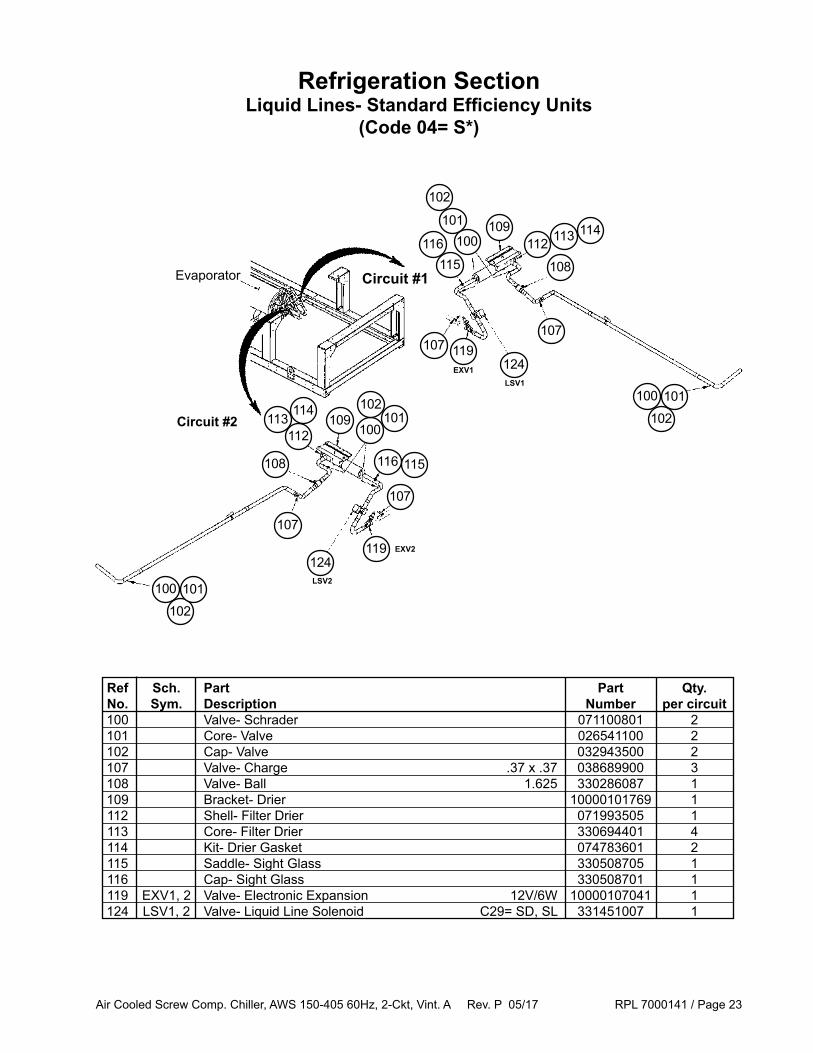
Refrigeration SectionLiquid Lines- Standard Efficiency Units
(Code 04= S*)
107 119107
124
Circuit #1
Circuit #2 102101100
113
108
112114109
100
102
101
116115
109100
102101
116 115
107
119124
113112
114
108
107
102101100
Ref Sch. Part Part Qty. No. Sym. Description Number per circuit 100 Valve- Schrader 071100801 2 101 Core- Valve 026541100 2 102 Cap- Valve 032943500 2 107 Valve- Charge .37 x .37 038689900 3 108 Valve- Ball 1.625 330286087 1 109 Bracket- Drier 10000101769 1 112 Shell- Filter Drier 071993505 1 113 Core- Filter Drier 330694401 4 114 Kit- Drier Gasket 074783601 2 115 Saddle- Sight Glass 330508705 1 116 Cap- Sight Glass 330508701 1 119 EXV1, 2 Valve- Electronic Expansion 12V/6W 10000107041 1 124 LSV1, 2 Valve- Liquid Line Solenoid C29= SD, SL 331451007 1
Evaporator
LSV2
LSV1EXV1
EXV2

Air Cooled Screw Comp. Chiller, AWS 150-405 60Hz, 2-Ckt, Vint. A Rev. P 05/17 RPL 7000141 / Page 24
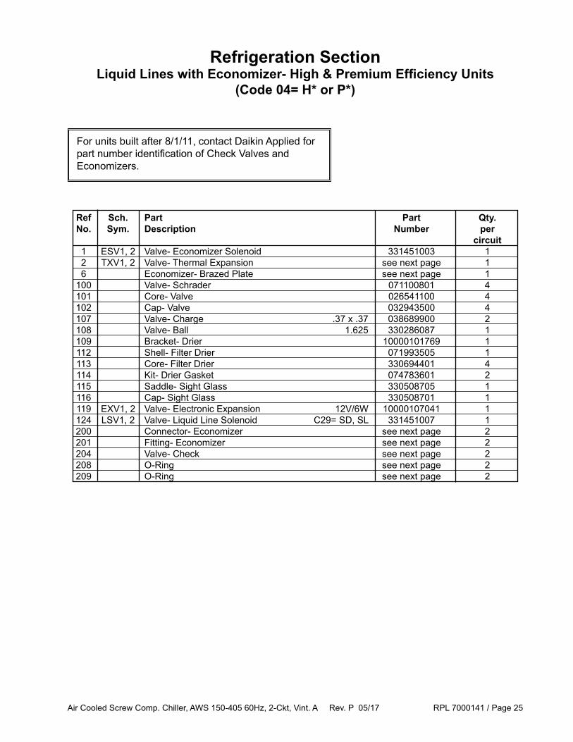
Refrigeration SectionLiquid Lines with Economizer- High & Premium Efficiency Units
(Code 04= H* or P*)
116115
From Economizer S4
109
112
204
101
201
200
100
102101
107
119
107
124
101
100102
21
102
101100
Line Between Economizer and Compressor
Detail
ESV_
To Evaporator
From Economizer S2
S1S4
S2S3
Economizer
Connects To Evaporator
To S1
From Condenser
From Liquid Line Tee
Liquid
Line
Tee
To Compressor
From
Economizer
S4
To Compressor
Compressor Economizer Connection
Detail
102
101100
102
101100
From Condenser
Representation ofCircuit 1 ShownConfiguration
may vary(Circuit 2 has same components)
Condenser to EconomizerDetail
Economizer to Evaporator
Detail
Circuit 1
Circuit 2
From ESV
Equalization
Tube
Evaporator
6
100 102 114
108
113
TXV_
EXV_
LSV_
208 209
For units built after 8/1/11, contact Daikin Applied for part number identification of Check Valves and Economizers.
Air Cooled Screw Comp. Chiller, AWS 150-405 60Hz, 2-Ckt, Vint. A Rev. P 05/17 RPL 7000141 / Page 25
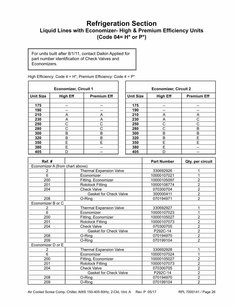
Refrigeration SectionLiquid Lines with Economizer- High & Premium Efficiency Units
(Code 04= H* or P*)
Ref Sch. Part Part Qty. No. Sym. Description Number per circuit 1 ESV1, 2 Valve- Economizer Solenoid 331451003 1 2 TXV1, 2 Valve- Thermal Expansion see next page 1 6 Economizer- Brazed Plate see next page 1 100 Valve- Schrader 071100801 4 101 Core- Valve 026541100 4 102 Cap- Valve 032943500 4 107 Valve- Charge .37 x .37 038689900 2 108 Valve- Ball 1.625 330286087 1 109 Bracket- Drier 10000101769 1 112 Shell- Filter Drier 071993505 1 113 Core- Filter Drier 330694401 4 114 Kit- Drier Gasket 074783601 2 115 Saddle- Sight Glass 330508705 1 116 Cap- Sight Glass 330508701 1 119 EXV1, 2 Valve- Electronic Expansion 12V/6W 10000107041 1 124 LSV1, 2 Valve- Liquid Line Solenoid C29= SD, SL 331451007 1 200 Connector- Economizer see next page 2 201 Fitting- Economizer see next page 2 204 Valve- Check see next page 2 208 O-Ring see next page 2 209 O-Ring see next page 2
For units built after 8/1/11, contact Daikin Applied for part number identification of Check Valves and Economizers.
Air Cooled Screw Comp. Chiller, AWS 150-405 60Hz, 2-Ckt, Vint. A Rev. P 05/17 RPL 7000141 / Page 26
Unit Size High Eff Premium Eff 175 -- -- 190 -- -- 210 A A 230 A A 250 C C 280 C C 300 B B 320 B B 350 E E 380 E -- 405 D --
Unit Size High Eff Premium Eff
175 -- -- 190 -- -- 210 A A 230 A C 250 C C 280 C B 300 B B 320 B E 350 E E 380 E -- 405 D --
Economizer, Circuit 1 Economizer, Circuit 2
Ref. # Part Number Qty. per circuit Economizer A (from chart above) 2 Thermal Expansion Valve 330692926 1 6 Economizer 10000107021 1 200 Fitting, Economizer 10000105097 2 201 Rotolock Fitting 10000108774 2 204 Check Valve 070300704 2 Gasket for Check Valve 300000411 2 208 O-Ring 070194971 2 Economizer B or C 2 Thermal Expansion Valve 330692927 1 6 Economizer 10000107023 1 200 Fitting, Economizer 10000105027 2 201 Rotolock Fitting 10000107073 2 204 Check Valve 070300705 2 Gasket for Check Valve P292C-14 2 208 O-Ring 070194970 2 209 O-Ring 070199104 2 Economizer D or E 2 Thermal Expansion Valve 330692928 1 6 Economizer 10000107024 1 200 Fitting, Economizer 10000105027 2 201 Rotolock Fitting 10000107073 2 204 Check Valve 070300705 2 Gasket for Check Valve P292C-14 2 208 O-Ring 070194970 2 209 O-Ring 070199104 2
Refrigeration SectionLiquid Lines with Economizer- High & Premium Efficiency Units
(Code 04= H* or P*)
High Efficiency: Code 4 = H*, Premium Efficiency: Code 4 = P*
For units built after 8/1/11, contact Daikin Applied for part number identification of Check Valves and Economizers.
Air Cooled Screw Comp. Chiller, AWS 150-405 60Hz, 2-Ckt, Vint. A Rev. P 05/17 RPL 7000141 / Page 27
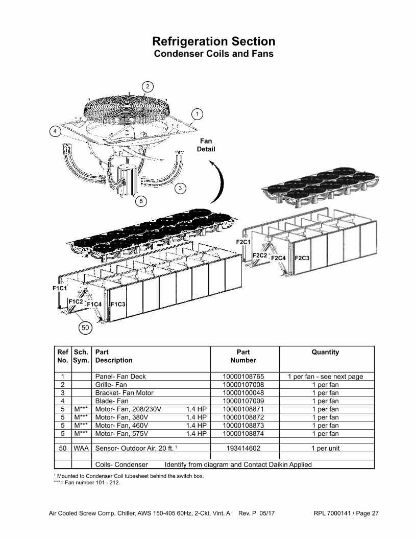
Refrigeration SectionCondenser Coils and Fans
1 Mounted to Condenser Coil tubesheet behind the switch box.***= Fan number 101 - 212.
4
2
1
3
5
Fan Detail
50
Ref Sch. Part Part Quantity No. Sym. Description Number
1 Panel- Fan Deck 10000108765 1 per fan - see next page 2 Grille- Fan 10000107008 1 per fan 3 Bracket- Fan Motor 10000100048 1 per fan 4 Blade- Fan 10000107009 1 per fan 5 M*** Motor- Fan, 208/230V 1.4 HP 10000108871 1 per fan 5 M*** Motor- Fan, 380V 1.4 HP 10000108872 1 per fan 5 M*** Motor- Fan, 460V 1.4 HP 10000108873 1 per fan 5 M*** Motor- Fan, 575V 1.4 HP 10000108874 1 per fan
50 WAA Sensor- Outdoor Air, 20 ft. 1 193414602 1 per unit
Coils- Condenser Identify from diagram and Contact Daikin Applied
F1C1
F1C2 F1C4 F1C3
F2C1
F2C2 F2C4 F2C3

Air Cooled Screw Comp. Chiller, AWS 150-405 60Hz, 2-Ckt, Vint. A Rev. P 05/17 RPL 7000141 / Page 28
Unit Starter Std. Eff. High Eff. Premium Eff. Size (Code 9) Ckt 1 Ckt 2 Total Ckt1 Ckt 2 Total Ckt 1 Ckt 2 Total 150 VF or VE 5 5 = 10 -- -- -- -- 175 WD or SS 5 5 = 10 -- -- -- -- 175 VF or VE 6 6 = 12 -- -- -- -- 190 WD or SS 6 6 = 12 -- -- -- -- 190 VF or VE 6 6 = 12 -- -- -- -- 210 any 6 6 = 12 6 6 = 12 8 8 = 16 230 any 7 7 = 14 7 7 = 14 9 9 = 18 250 any 7 7 = 14 7 7 = 14 9 9 = 18 280 any 8 8 = 16 8 8 = 16 10 10 = 20 300 any 8 8 = 16 8 8 = 16 10 10 = 20 320 any 10 10 = 20 10 10 = 20 10 12 = 22 350 any 10 10 = 20 10 10 = 20 12 12 = 24 380 any -- -- 10 12 = 22 -- -- 405 any -- -- 12 12 = 24 -- --
Refrigeration SectionFan Totals per Unit
Standard Efficiency: Code 4 = S*, High Efficiency: Code 4 = H*, Premium Efficiency: Code 4 = P*
Code 9: VF = VFD Starter without EMI Filter VE = VFD Starter with EMI Filter WD = Wye Delta Starter with Compressor Overloads SS = Solid State Starter
Air Cooled Screw Comp. Chiller, AWS 150-405 60Hz, 2-Ckt, Vint. A Rev. P 05/17 RPL 7000141 / Page 29
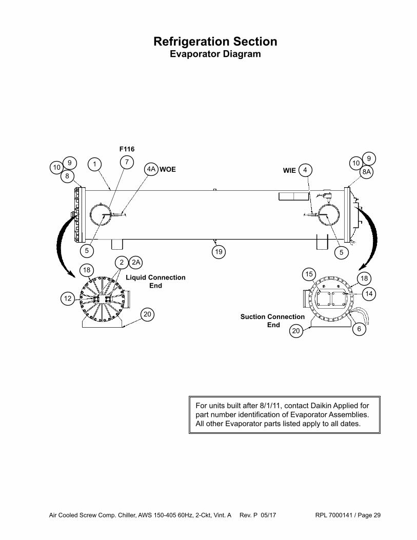
Refrigeration SectionEvaporator Diagram
1
5
4A 47
8
6
5
WOE WIE
F116
218
20
12
2A
109
Liquid Connection End
Suction Connection End
20
14
15 18
19
8A10
9
For units built after 8/1/11, contact Daikin Applied for part number identification of Evaporator Assemblies. All other Evaporator parts listed apply to all dates.

Air Cooled Screw Comp. Chiller, AWS 150-405 60Hz, 2-Ckt, Vint. A Rev. P 05/17 RPL 7000141 / Page 30
Evap Description / Unit Sizes Starter Left-Hand Evap Right-Hand Evap Group (Code 9) Code 23 = VL Code 23 = VR Standard Efficiency Units A 150A VF or VE 10000108710 10000108740 A 175A WD or SS 10000108710 10000108740 A 175A VF or VE 10000108710 10000108740 A 190A WD or SS 10000108710 10000108740 A 190A VF or VE 10000108712 10000108742 A 210A any 10000108712 10000108742 A 230A any 10000108714 10000108744 A 250A any 10000108714 10000108744 B 280A any 10000108717 10000108747 B 300A any 10000108717 10000108747 B 320A any 10000108719 10000108749 B 350A any 10000108719 10000108749 High Efficiency Units A 210A any 10000108712 10000108742 A 230A any 10000108714 10000108744 A 250A any 10000108714 10000108744 B 280A any 10000108717 10000108747 B 300A any 10000108717 10000108747 B 320A any 10000108719 10000108749 B 350A any 10000108719 10000108749 B 380A any 10000108719 10000108749 B 405A any 10000108719 10000108749 Premium Efficiency Units B 210A any 10000108725 10000108750 B 230A any 10000108725 10000108750 C 250A any 10000108735 10000108755 C 280A any 10000108735 10000108755 C 300A any 10000108735 10000108755 C 320A any 10000108737 10000108757 C 350A any 10000108737 10000108757
For more Evaporator components, determine Evap Group from above chart and see next page.
Refrigeration SectionEvaporator Components
Evap Ref Sch. Part Part No. Qty. Group No. Sym. Description All 4 WIE Sensor- Evaporator Inlet, 60 ft. 193414606 1 All 4A WOE Sensor- Evaporator Outlet, 60 ft. 193414606 1 All 5 Well- Sensor E44070058 2 All 7 F116 Switch- Evaporator Flow 331796201 1 All Cable- for Evap Flow Switch 330571403 1 All 19 Valve- Mini Ball, 0.50 NPT 071596201 1 All 20 Pad- Vibration, 4" x 3.25" 735008725 4 All Insulation 047662050 as needed
Ref. No. 1: Evaporator Assembly
Standard Efficiency: Code 4 = S*, High Efficiency: Code 4 = H*, Premium Efficiency: Code 4 = P*
For units built after 8/1/11, contact Daikin Applied for part number identification of Evaporator Assemblies. All other Evaporator parts listed apply to all dates.

Air Cooled Screw Comp. Chiller, AWS 150-405 60Hz, 2-Ckt, Vint. A Rev. P 05/17 RPL 7000141 / Page 31
Evap Ref Sch. Part Part No. Qty. Group No. Sym. Description
A, B 2 Ferrule- Liquid E44070016 2 C 2 Ferrule- Liquid E44070043 2
A, B 2A Flange- Liquid E44060007 2 C 2A Flange- Liquid E44060009 2
A 6 R5 Heater- Evaporator E44196011 1 B, C 6 R5 Heater- Evaporator E44191111 1
A 8 Gasket- Inlet Head E44134053 1 B 8 Gasket- Inlet Head E44135062 1 C 8 Gasket- Inlet Head E44136601 1
A 8A Gasket- Suction Head E44134053 1 B 8A Gasket- Suction Head E44135062 1 C 8A Gasket- Suction Head E44136601 1
A 9 Gasket- Distributor E44134072 2 B 9 Gasket- Distributor E44135072 2 C 9 Gasket- Distributor E44136602 2
A 10 O'Ring- Tube Sheet E0041600 2 B 10 O'Ring- Tube Sheet E0062000 2
A, B 12 Bolt- Liquid Ferrule E10125400 8 C 12 Bolt- Liquid Ferrule E10154000 8
A 14 Bolt- Suction Connection E14155000 8 B, C 14 Bolt- Suction Connection E14156000 8
A 15 O'Ring- Suction E44130201 2 B 15 O'Ring- Suction E44136600 2 C 15 O'Ring- Suction E44130201 2
A 18 Bolt- Head (M16 x 1.5 x 70) E16157000 48 B 18 Bolt- Head (M16 x 1.5 x 70) E16157000 56 B 18 Bolt- Head (M14- 16 x 1.5 x 100) E16151000 2 B 18 Bolt- Head (M14- 16 x 1.5 x 135) E16151350 2 C 18 Bolt- Head (M14- 16 x 1.5 x 130) E16151300 22 C 18 Bolt- Head (M16 x 1.5 x 145) E16151400 4 C 18 Bolt- Head (M16 x 1.5 x 70) E16157000 22
Refrigeration SectionEvaporator Components

Air Cooled Screw Comp. Chiller, AWS 150-405 60Hz, 2-Ckt, Vint. A Rev. P 05/17 RPL 7000141 / Page 32
Coil and Base Frame Grilles
Base Frame GrillesCode 28=F, C
16 Fan Unit shown
Ref Part Part Quantity No. Description Number 1 Grille- Base 1 10000108704 1 per fan 2 Grille- Left Hand Rear 2 10000108705 1 per unit 3 Grille- Right Hand Rear 2 10000108706 1 per unit 4 Grille- Front 2 10000108707 1 per unit
3
14
2
1 Each base grille is attached using four (4) screws p/n 331578401.2 Each front or rear grille is attached using six (6) screws p/n 331578401. Front Grille not used on units with VFD Starters.
Coil GrillesCode 28=G, F
16 Fan Unit shown
1
Ref Part Part Quantity No. Description Number 1 Grille- Coil 1 10000107007 1 per fan1 Each coil louver is attached using six (6) screws p/n 331578401.
Std. High Prem. Unit Starter Eff. Eff. Eff. Size (Code 9) Total Total Total Fans Fans Fans 150 VF orVE 10 -- -- 175 WD or SS 10 -- -- 175 VF or VE 12 -- -- 190 WD or SS 12 -- -- 190 VF or VE 12 -- -- 210 any 12 12 16 230 any 14 14 18 250 any 14 14 18 280 any 16 16 20 300 any 16 16 20 320 any 20 20 22 350 any 20 20 24 380 any -- 22 -- 405 any -- 24 --
Standard Efficiency: Code 4 = S*High Efficiency: Code 4 = H*Premium Efficiency: Code 4 = P*
Air Cooled Screw Comp. Chiller, AWS 150-405 60Hz, 2-Ckt, Vint. A Rev. P 05/17 RPL 7000141 / Page 33
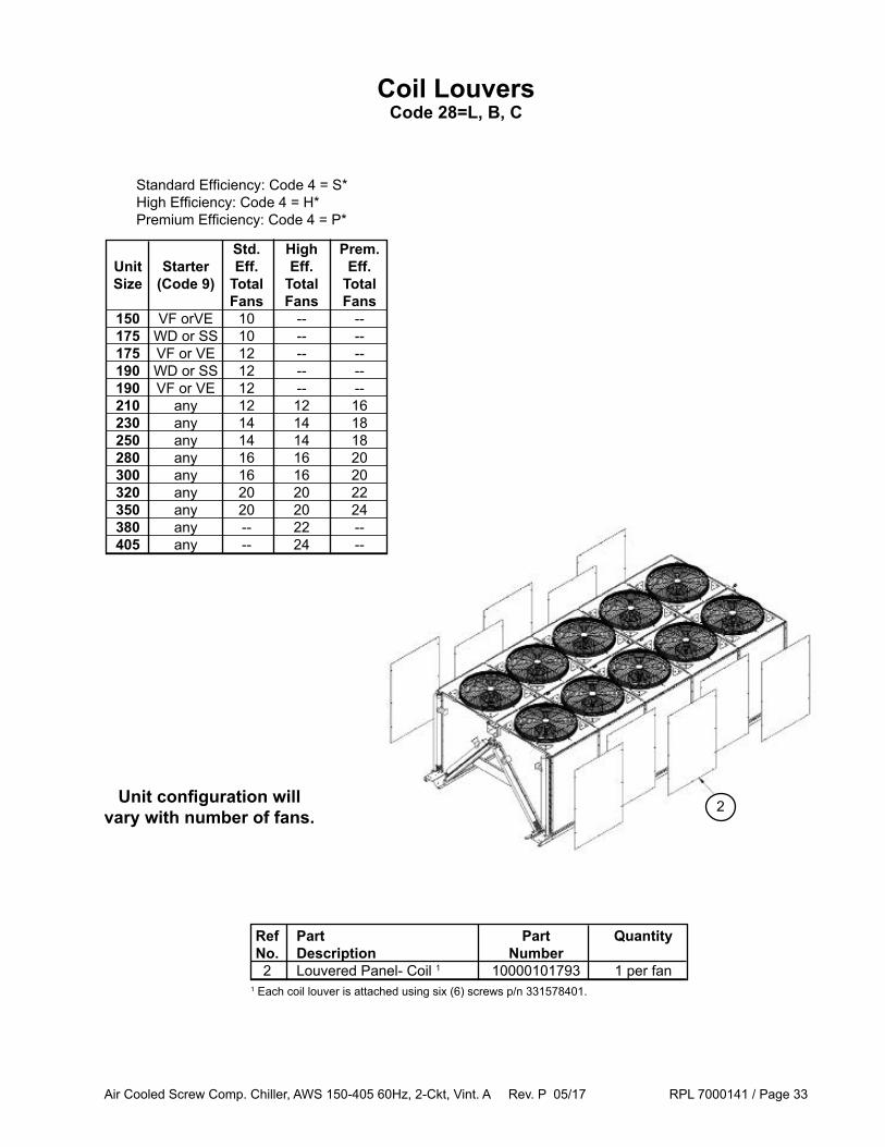
Coil LouversCode 28=L, B, C
Ref Part Part Quantity No. Description Number 2 Louvered Panel- Coil 1 10000101793 1 per fan
2
1 Each coil louver is attached using six (6) screws p/n 331578401.
Standard Efficiency: Code 4 = S*High Efficiency: Code 4 = H*Premium Efficiency: Code 4 = P*
Std. High Prem. Unit Starter Eff. Eff. Eff. Size (Code 9) Total Total Total Fans Fans Fans 150 VF orVE 10 -- -- 175 WD or SS 10 -- -- 175 VF or VE 12 -- -- 190 WD or SS 12 -- -- 190 VF or VE 12 -- -- 210 any 12 12 16 230 any 14 14 18 250 any 14 14 18 280 any 16 16 20 300 any 16 16 20 320 any 20 20 22 350 any 20 20 24 380 any -- 22 -- 405 any -- 24 --
Unit configuration will vary with number of fans.
Air Cooled Screw Comp. Chiller, AWS 150-405 60Hz, 2-Ckt, Vint. A Rev. P 05/17 RPL 7000141 / Page 34
16 Fan Unit
3
4 24
4
4
6
5
6
5
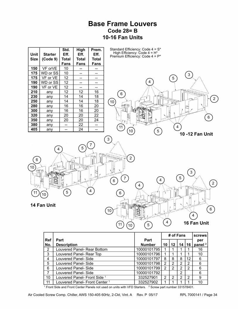
Base Frame LouversCode 28= B
10-16 Fan Units
# of Fans screws Ref Part Part per No. Description Number 10 12 14 16 panel 2
2 Louvered Panel- Rear Bottom 10000101795 1 1 1 1 16 3 Louvered Panel- Rear Top 10000101796 1 1 1 1 10 4 Louvered Panel- Side 10000101797 8 8 8 12 6 5 Louvered Panel- Side 10000101798 2 2 2 2 6 6 Louvered Panel- Side 10000101799 2 2 2 2 6 7 Louvered Panel- Side 10000101792 2 6 10 Louvered Panel- Front Side 1 332527901 2 2 2 2 9 11 Louvered Panel- Front Center 1 332527902 1 1 1 1 101 Front Side and Front Center Panels not used on units with VFD Starters. 2 Screw part number 331578401.
Standard Efficiency: Code 4 = S*High Efficiency: Code 4 = H*
Premium Efficiency: Code 4 = P*
10 -12 Fan Unit
14 Fan Unit
3
4
2
4
6
5
6
5
3
4
2
5
4
6
5
6
7
10
10
11
7
10
10
11
10
10
11
Std. High Prem. Unit Starter Eff. Eff. Eff. Size (Code 9) Total Total Total Fans Fans Fans 150 VF orVE 10 -- -- 175 WD or SS 10 -- -- 175 VF or VE 12 -- -- 190 WD or SS 12 -- -- 190 VF or VE 12 -- -- 210 any 12 12 16 230 any 14 14 18 250 any 14 14 18 280 any 16 16 20 300 any 16 16 20 320 any 20 20 22 350 any 20 20 24 380 any -- 22 -- 405 any -- 24 --

Air Cooled Screw Comp. Chiller, AWS 150-405 60Hz, 2-Ckt, Vint. A Rev. P 05/17 RPL 7000141 / Page 35
18 Fan Unit
3
4
4
6
52
4
45
6
Base Frame LouversCode 28= B
18-20 Fan Units
# of Fans screws Ref Part Part per No. Description Number 18 20 panel 2
2 Louvered Panel- Rear Bottom 10000101795 1 1 16 3 Louvered Panel- Rear Top 10000101796 1 1 10 4 Louvered Panel- Side 10000101797 14 16 6 5 Louvered Panel- Side 10000101798 2 2 6 6 Louvered Panel- Side 10000101799 2 2 6 10 Louvered Panel- Front Side 1 332527901 2 2 9 11 Louvered Panel- Front Center 1 332527902 1 1 101 Front Side and Front Center Panels not used on units with VFD Starters. 2 Screw part number 331578401.
3
4
4
6
5
2
4
4
5
101110
101110
20 Fan Unit
Standard Efficiency: Code 4 = S*High Efficiency: Code 4 = H*
Premium Efficiency: Code 4 = P*
Std. High Prem. Unit Eff. Eff. Eff. Size Total Total Total Fans Fans Fans 175 10 -- -- 190 12 -- -- 210 12 12 16 230 14 14 18 250 14 14 18 280 16 16 20 300 16 16 20 320 20 20 22 350 20 20 24 380 -- 22 -- 405 -- 24 --
Air Cooled Screw Comp. Chiller, AWS 150-405 60Hz, 2-Ckt, Vint. A Rev. P 05/17 RPL 7000141 / Page 36
6
4 56
45
32
4
46
5
5
6
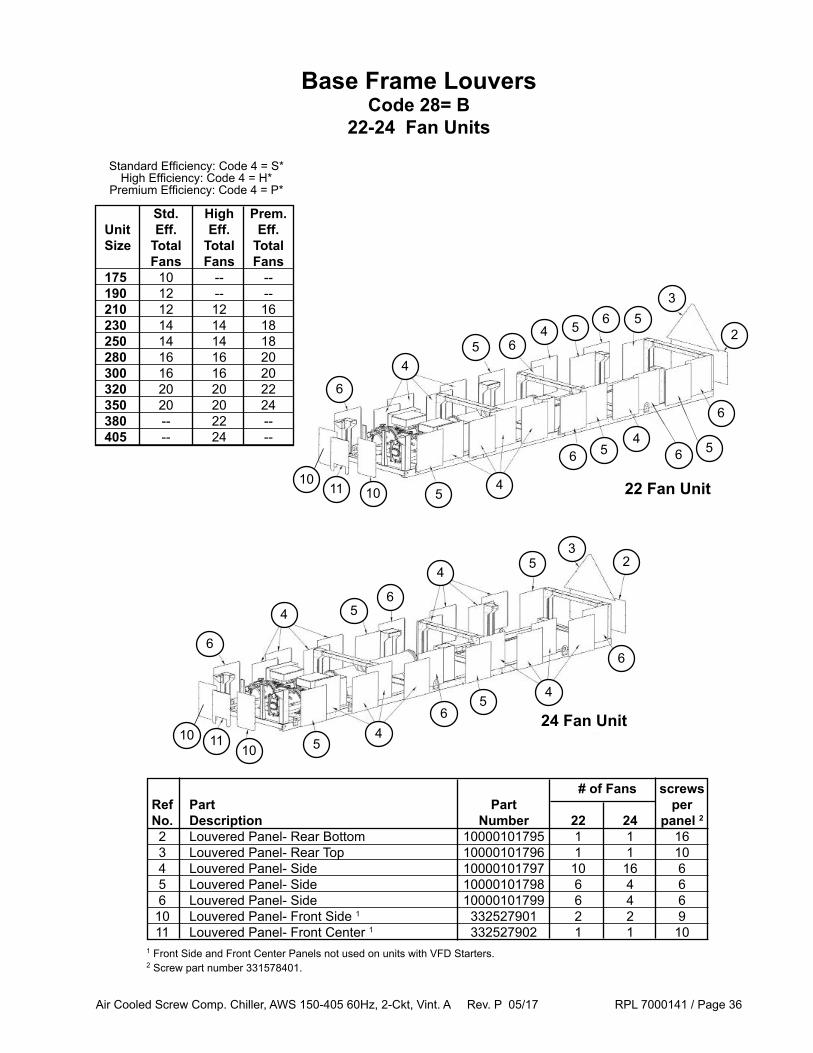
Base Frame LouversCode 28= B
22-24 Fan Units
3
4
24 5 6
6
5
65
56
5
6
4
45
6
101110
101110
22 Fan Unit
24 Fan Unit
# of Fans screws Ref Part Part per No. Description Number 22 24 panel 2
2 Louvered Panel- Rear Bottom 10000101795 1 1 16 3 Louvered Panel- Rear Top 10000101796 1 1 10 4 Louvered Panel- Side 10000101797 10 16 6 5 Louvered Panel- Side 10000101798 6 4 6 6 Louvered Panel- Side 10000101799 6 4 6 10 Louvered Panel- Front Side 1 332527901 2 2 9 11 Louvered Panel- Front Center 1 332527902 1 1 101 Front Side and Front Center Panels not used on units with VFD Starters. 2 Screw part number 331578401.
Standard Efficiency: Code 4 = S*High Efficiency: Code 4 = H*
Premium Efficiency: Code 4 = P*
Std. High Prem. Unit Eff. Eff. Eff. Size Total Total Total Fans Fans Fans 175 10 -- -- 190 12 -- -- 210 12 12 16 230 14 14 18 250 14 14 18 280 16 16 20 300 16 16 20 320 20 20 22 350 20 20 24 380 -- 22 -- 405 -- 24 --

Air Cooled Screw Comp. Chiller, AWS 150-405 60Hz, 2-Ckt, Vint. A Rev. P 05/17 RPL 7000141 / Page 37
61
2
34
5
ControlsUnits with Wye-Delta or Solid State Starter (Code 9 = WD, SS)
Box Locations and Label Detail
Control Panel Power Panel- Left Side Power Panel- Right Side
Solid State Starter Panel(one per compressor)
Circuit 2 shown
Wye- DeltaStarter Panel(one per compressor)
Circuit 2 shown
or
Terminal Box(one per compressor)
For all control components not detailed or for unit specific controls (i.e. main disconnect, solid state contactors), please contact Daikin Applied with the Control Box Serial Number and Control Box Part Number. These numbers are located on the Control box rating label (see example below). This label is found inside the panel.
Control Box Serial Number“S” + Year + ##### + detail#
Control Box Part Number
Label Detail
Circuit 2 Starter Box
Fan VFDlocation

Air Cooled Screw Comp. Chiller, AWS 150-405 60Hz, 2-Ckt, Vint. A Rev. P 05/17 RPL 7000141 / Page 38
F59 F12Q12 K11 AC REC1
UC FC
Q0
Q1
Q2
Sch. Part Part Sym. Description Number Qty. AC Expansion Controller- Alarms 193407501 1 AWM Advanced Web Module 2 193408502 1 FC Expansion Controller- Fans 193407601 1 F12 Fuse- Outlet 300046446 1 F59 Fuse- Evaporator Heater Protection 300046455 1 K11 Relay- Emergency Stop 300046445 1 Q0 Switch- Unit Shut Off 300046456 1 Q1 Switch- Pumpdown Circuit #1 300046456 1 Q2 Switch- Pumpdown Circuit #2 300046456 1 Q11 Switch- Emergency Stop 1 300046448 1 Q12 Circuit Breaker 300046447 1 REC1 Receptacle 330472601 1 UC Controller- MicroTech III 193407301 1
Q11
1 Mounted through the door.2 This control board must be programmed in order to function correctly. When ordering a replacement, provide the unit model and se-rial number so that unit specific software code can be loaded before shipment.
ControlsUnits with Wye-Delta or Solid State Starter (Code 9 = WD, SS)
Control Panel Detail

Air Cooled Screw Comp. Chiller, AWS 150-405 60Hz, 2-Ckt, Vint. A Rev. P 05/17 RPL 7000141 / Page 39
K16KM102F112
T2
GFR1
UC F230
T1
Sch. Part Part Sym. Description Number Qty. AM1 Ammeter Code 14= A See next page 1 F100, 200 Circuit Breaker- Circuit #1 Fans 600V/100A 300043195 2 F112, 212 Phase Voltage Monitor 300040118 2 F120 Fuse- Control Transformer 208/230V 300046446 1 F120 Fuse- Control Transformer 380V 300046449 1 F120 Fuse- Control Transformer 460V, 575V 300046450 1 F130, 230 Fuse- PVM 300046454 2 GFR1, 2 Relay- Ground Fault 330315101 2 K16, 26 Relay- Fan Motor 300046445 2 KM102- 107 Contactor- Fans Circuit #1 300046444 1/fan KM202- 207 Contactor- Fans Circuit #2 300046444 1/fan LR1, 2 Line Reactor 460V 300046411 2 Q101- 107 MSP- Fans Circuit #1 300046443 1/fan Q201- 207 MSP- Fans Circuit #2 300046443 1/fan T2 Transformer 24V 300046472 1 T1 Transformer- Control 208/230/460V:120V 300046451 1 T1 Transformer- Control 380V:120V 300046453 1 T1 Transformer- Control 575V:120V 300046452 1 VFD1, 2 Fan VFD 2 208/230V 300046457 2 VFD1, 2 Fan VFD 2 380V, 460V 300046412 2 VFD1, 2 Fan VFD 2 575V 300046259 2 VM1 Volt Meter: 0- 600V 1 Code 14= A 300046460 1
GFR2
F130
F100
F200
F212
F120
KM103
KM104
KM105
KM107
Q101 Q102 Q103 Q104 Q105 Q107
K26KM202
KM203
KM204
KM205
KM207
Q201 Q202 Q203 Q204 Q205 Q207
AM1 VM1
1 Mounted on the outside of the power panel door.2 Not shown - The Fan VFDs are located on the cross rail near the front of the evaporator.
LR1
LR2
ControlsUnits with Wye-Delta or Solid State Starter (Code 9 = WD, SS)
Power Panel Detail

Air Cooled Screw Comp. Chiller, AWS 150-405 60Hz, 2-Ckt, Vint. A Rev. P 05/17 RPL 7000141 / Page 40
ControlsUnits with Wye-Delta or Solid State Starter (Code 9 = WD, SS)
Power Panel Detail
Voltage Unit Size Part Number 208V, 230V all 0-1500A 300046459 380V 175-250 0-600A 300046458 380V 280AS 0-1500A 300046459 380V 280AH, 280AP 0-600A 300046458 380V 300-405 0-1500A 300046459
460V, 575V 175-280 0-600A 300046458 460V, 575V 350-405 0-1500A 300046459
AM1: Ammeter

Air Cooled Screw Comp. Chiller, AWS 150-405 60Hz, 2-Ckt, Vint. A Rev. P 05/17 RPL 7000141 / Page 41
Sch. Sym. Part Description Q10 Switch- Main Disconnect Units with Disc Switch: C12= DC, DH, WN, WH Q20 Switch- Main Disconnect Only on Multi-Point units: C12= WN, WH P10 Power Block- Main Units with Power Block: C12= PC F1, 2 Circuit Breaker- Compressor 1, 2, 3 Only on Single Point units: C12= PC, DC, DH
Q10or
P10
F1 or Q20 F2
GFR1 CT
Single Point Connection (Code 12= PC, DC, DH) Shown
ControlsUnits with Wye-Delta or Solid State Starter (Code 9 = WD, SS)
Power Panel Detail
To insure proper replacement part number for any of the items above, contact Daikin Applied with the Control Box Serial Number and Control Box Part number. See earlier Controls page for Label example.
Voltage Unit Size Part Number Multi-Point Units all all 300043558 (Code 12 = WN, WH) 208/230V all 349937410 380V 175-250 300043558 380V 280AS 349937410 380V 280AH, AP 300043558 380V 300AS 349937410 380V 300AH, AP 300043558 380V 320-405 349937410 460V 175-300 300043558 460V 320AS 349937410 460V 320AH 300043558 460V 320AP 349937410 460V 350-405 349937410
GFR1 CT: Ground Fault Current Sensor
Single Point Units (Code 12 = PC, DC, DH)
Sch. Sym. Part Description Part Number M10 Control Box Exhaust Fan 300047148
M10
Air Cooled Screw Comp. Chiller, AWS 150-405 60Hz, 2-Ckt, Vint. A Rev. P 05/17 RPL 7000141 / Page 42
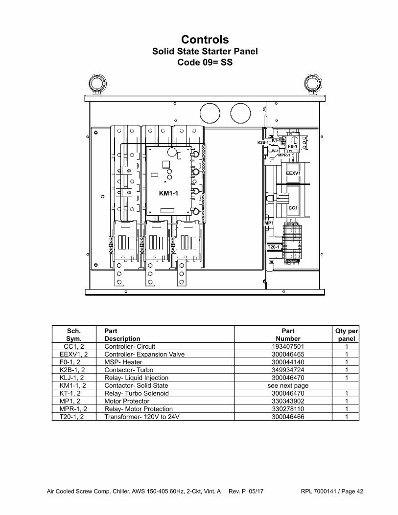
ControlsSolid State Starter Panel
Code 09= SS
KM1-1
T20-1
MP1
CC1
EEXV1
F0-1
MPR-1
KT-1
LJV-1
K2B-1
Sch. Part Part Qty per Sym. Description Number panel CC1, 2 Controller- Circuit 193407501 1 EEXV1, 2 Controller- Expansion Valve 300046465 1 F0-1, 2 MSP- Heater 300044140 1 K2B-1, 2 Contactor- Turbo 349934724 1 KLJ-1, 2 Relay- Liquid Injection 300046470 1 KM1-1, 2 Contactor- Solid State see next page KT-1, 2 Relay- Turbo Solenoid 300046470 1 MP1, 2 Motor Protector 330343902 1 MPR-1, 2 Relay- Motor Protection 330278110 1 T20-1, 2 Transformer- 120V to 24V 300046466 1

Air Cooled Screw Comp. Chiller, AWS 150-405 60Hz, 2-Ckt, Vint. A Rev. P 05/17 RPL 7000141 / Page 43
KM1-1,2 Contactor Assy AWS 150-280, Std Eff, circuit 1 AWS 150-250, Std Eff, circuit 2 300048732 used on: AWS 210-320, High Eff, circuit 1 AWS 210-300, High Eff, circuit 2 AWS 210-320, Prem Eff, circuit 1 AWS 210-300, Prem Eff, circuit 2
Sch. Part Part Qty per Sym. Description Number panel KM1-1, 2 Contactor - Solid State, complete assembly 300048732 1 includes:' 1 MX2 Low Voltage Motor Starter Card 300048820 1 2 Contactor Bypass, 75A, 50HP, 120V 300040148 3 3 Surge Suppressor 300043749 3 5 SCR, 660A, 1800V 300042134 6 6 Current Transformer 300042127 3 7 Snubber Assembly 300043777 1
Sch. Part Part Qty per Sym. Description Number panel KM1-1, 2 Contactor - Solid State, complete assembly 300047990 1 includes:' 1 MX2 Low Voltage Motor Starter Card 300048820 1 2 Contactor Bypass, 85A, 60HP, 120V 300043218 3 3 Surge Suppressor 300043749 3 5 SCR, 660A, 1800V 300042134 6 6 Current Transformer 300042127 3 7 Snubber Assembly 300043777 1
ControlsSolid State Starter Panel
Code 09= SS
KM1-1,2 Contactor Assy AWS 300-350, Std. Eff, circuit 1 AWS 280-350, Std Eff, circuit 2 300047990 used on: AWS 350-405, High Eff, circuit 1 AWS 320-405, High Eff, circuit 2 AWS 350, Prem Eff, circuit 1 AWS 320-350, Prem Eff, circuit 2
1
23
5 5 5
6
7MX2 Card

Air Cooled Screw Comp. Chiller, AWS 150-405 60Hz, 2-Ckt, Vint. A Rev. P 05/17 RPL 7000141 / Page 44
T20-1
MP1
CC1
EEXV1
FO-1
MPR-1
KT-1
LJV-1
K2B-1
Sch. Part Part Qty per Sym. Description Number panel CC1, 2 Controller- Circuit 193407501 1 EEXV1, 2 Controller- Expansion Valve 300046465 1 F0-1 , 2 Heater- MSP 300044140 1 F5-1, 2 Overload- Thermal See next page K2B-1, 2 Contactor- Turbo Relay 349934724 1 KLJ-1, 2 Relay- Liquid Injection 300046470 1 KM1-1, 2 Contactor- Wye Delta See next page KM2-1, 2 Contactor- Wye Delta See next page KM3-1, 2 Contactor- Wye Delta See next page KT-1, 2 Relay- Turbo Solenoid 300046470 1 KT1-1, 2 Time Delay- Starter 300046469 1 MP1, 2 Motor Protector 330343902 1 MPR-1, 2 Relay- Motor Protection 330278110 1 T20-1, 2 Transformer- 120V to 24V 300046466 1
KT1-1
KM3-1 KM2-1 KM1-1
F5-1
ControlsWye-Delta Starter Panel
Code 09= WD

Air Cooled Screw Comp. Chiller, AWS 150-405 60Hz, 2-Ckt, Vint. A Rev. P 05/17 RPL 7000141 / Page 45
142A all 105A 300042917 105A 300042917 107A 300046492 200A all 150A 300042135 105A 300042917 130A 300046493 241A all 180A 300040787 180A 300040787 150A 300046494 275A all 250A 300042136 180A 300040787 150A 300046494 317A all 250A 300042136 180A 300040787 200A 300046495 413A 208V 300A 300042137 300A 300042137 250A 300046496 413A 230V 300A 300042137 180A 300040787 250A 300046496 413A 380V w/o Economizer 300A 300042137 300A 300042137 250A 300046496 413A 380V w/ Economizer 300A 300042137 180A 300040787 250A 300046496 551A all 400A 300042138 300A 300042137 350A 300046497
Starter Compressor Contactors Thermal Max Unit KM1-1, 2 Overload RLA Voltage KM2-1, 2 KM3-1,2 F5-1, 2
Refer to the Starter Label to identify the Starter Max RLA.
ControlsWye-Delta Starter Panel
Code 09= WD
Starter Label example.

Air Cooled Screw Comp. Chiller, AWS 150-405 60Hz, 2-Ckt, Vint. A Rev. P 05/17 RPL 7000141 / Page 46
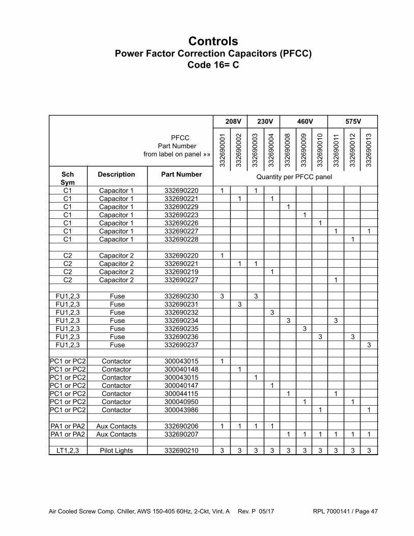
ControlsPower Factor Correction Capacitors (PFCC)
Code 16= C
12 Fan unit shown. Configuration similar for 10-20 Fan and 24 Fan units.For 22 Fan units, the PFCC panels are mounted on both sides of the evaporator.
Air Cooled Screw Comp. Chiller, AWS 150-405 60Hz, 2-Ckt, Vint. A Rev. P 05/17 RPL 7000141 / Page 47
ControlsPower Factor Correction Capacitors (PFCC)
Code 16= C
3326
9000
1
3326
9000
2
3326
9000
3
3326
9000
4
3326
9000
8
3326
9000
9
3326
9001
0
3326
9001
1
3326
9001
2
3326
9001
3
208V 230V 460V 575V PFCC
Part Number from label on panel »»
Quantity per PFCC panel Sch Description Part Number Sym C1 Capacitor 1 332690220 1 1 C1 Capacitor 1 332690221 1 1 C1 Capacitor 1 332690229 1 C1 Capacitor 1 332690223 1 C1 Capacitor 1 332690226 1 C1 Capacitor 1 332690227 1 1 C1 Capacitor 1 332690228 1
C2 Capacitor 2 332690220 1 C2 Capacitor 2 332690221 1 1 C2 Capacitor 2 332690219 1 C2 Capacitor 2 332690227 1 FU1,2,3 Fuse 332690230 3 3 FU1,2,3 Fuse 332690231 3 FU1,2,3 Fuse 332690232 3 FU1,2,3 Fuse 332690234 3 3 FU1,2,3 Fuse 332690235 3 FU1,2,3 Fuse 332690236 3 3 FU1,2,3 Fuse 332690237 3
PC1 or PC2 Contactor 300043015 1 PC1 or PC2 Contactor 300040148 1 PC1 or PC2 Contactor 300043015 1 PC1 or PC2 Contactor 300040147 1 PC1 or PC2 Contactor 300044115 1 1 PC1 or PC2 Contactor 300040950 1 1 PC1 or PC2 Contactor 300043986 1 1
PA1 or PA2 Aux Contacts 332690206 1 1 1 1 PA1 or PA2 Aux Contacts 332690207 1 1 1 1 1 1
LT1,2,3 Pilot Lights 332690210 3 3 3 3 3 3 3 3 3 3

Air Cooled Screw Comp. Chiller, AWS 150-405 60Hz, 2-Ckt, Vint. A Rev. P 05/17 RPL 7000141 / Page 48
ControlsUnits with VFD Starters (Code 9 = VE or VF)
Box Locations and Label Detail
Control Panel Power Panel
For all control components not detailed or for unit specific controls (i.e. main disconnect, solid state contactors), please contact Daikin Applied with the Control Box Serial Number and Control Box Part Number. These numbers are located on the Control box rating label (see example below). This label is found inside the panel.
Control Box Serial Number“S” + Year + ##### + detail#
Control Box Part Number
Label Detail
Fan VFDlocation

Air Cooled Screw Comp. Chiller, AWS 150-405 60Hz, 2-Ckt, Vint. A Rev. P 05/17 RPL 7000141 / Page 49
ControlsUnits with VFD Starters (Code 9 = VE or VF)
Control Side
T2
MP1, MP2
REC1
FUSES
FC, FC2
UC
EEXV1
K11K13K16
MPR1KLJ-1
CC1AC
EEXV2CC2
GFR1
T20-1, T20-2
K23K26
MPR2KLJ-2
Q110Q107Q105Q103Q102Q101
Q210Q207Q205Q203Q202Q201
Q0Q1Q2

Air Cooled Screw Comp. Chiller, AWS 150-405 60Hz, 2-Ckt, Vint. A Rev. P 05/17 RPL 7000141 / Page 50
Sch. Part Part Sym. Description Number Qty. AC Expansion Controller- Alarms 193407501 1 AWM Advanced Web Module 2 193408502 1 CC1,2 Controller- Circuit 193407501 2 EEXV1,2 Extension I/O for Electr. Exp. Valve (Code 29= LD or SL) 193407801 2 EEXV1,2 Extension I/O for Electr. Exp. Valve (Code 29= ND or SD) 193407901 2 F11 Fuse- Unit Controller, 10A Rejection Type 349937131 1 F12 Fuse- Outlet 349937131 1 F59 Fuse- Evaporator Heater Protection 349937116 1 F120 Fuse- Control Transformer, 12A Rejection Type (380V) 349937132 2 F120 Fuse- Control Transformer, 9A Rejection Type (460V) 349937130 2 FC, FC2 Expansion Controller- Fans 193407601 2 GFR1 Relay- Ground Fault 193432101 * K11 Relay- Emergency Stop 349934765 1 K13 Relay- Mechanical High Pressure, Circuit 1 349934764 1 K16 Relay- Fan Motor, Circuit 1 349934764 1 K23 Relay- Mechanical High Pressure, Circuit 2 349934764 1 K26 Relay- Fan Motor, Circuit 2 349934764 1 KLJ-1,2 Relay- Liquid Injection 193439901 2 MP1,2 Motor Thermal Protection 193445901 2 MPR1,2 Relay- Motor Protector 349934762 2 Q0 Switch- Unit Shut Off 001355000 1 Q1,2 Switch- Pumpdown 001355000 1 Q11 Switch- Emergency Stop (Not shown - mounted through the door) 193441101 1 REC1 Receptacle- Ground Fault Interrupter 039003600 1 T2 Transformer- 100VA, 115V-24V 330386105 1 T20-1,2 Transformer- 50VA, 115V-24V 349937203 2 UC Controller- MicroTech III 193407301 1 VFD1, 2 Fan VFD 1 193445601 21 Not shown - Fan VFDs are located on the left wall of the Control Side on units with VFD Starters. 2 This control board must be programmed in order to function correctly. When ordering a replacement, provide the unit model and serial number so that unit specific software code can be loaded before shipment.*Qty = 1 on Std Short Circuit units (Code 12 = PC,DC,WN); Qty = 3 High Short Circuit units (Code 12 = DH, WH)
Code 14=A Unit Size Efficiency Voltage Description Part Number Qty (Code 4) VM1 all all all Voltmeter- 0-600V 1 193446701 1
AM1 150 - 230 all all Ammeter- 0-600A 1 193446001 1 AM1 250 H 380V Ammeter- 0-600A 1 193446001 1 AM1 250 P 380V Ammeter- 0-1200A 1 193446002 1 AM1 250 H, P 460V Ammeter- 0-600A 1 193446001 1 AM1 280 H, P 380V Ammeter- 0-1200A 1 193446002 1 AM1 280 H, P 460V Ammeter- 0-600A 1 193446001 1 AM1 300 - 405 all all Ammeter- 0-1200A 1 193446002 1
1 Mounted on the outside of the control box door.
ControlsUnits with VFD Starters (Code 9 = VE or VF)
Control Side
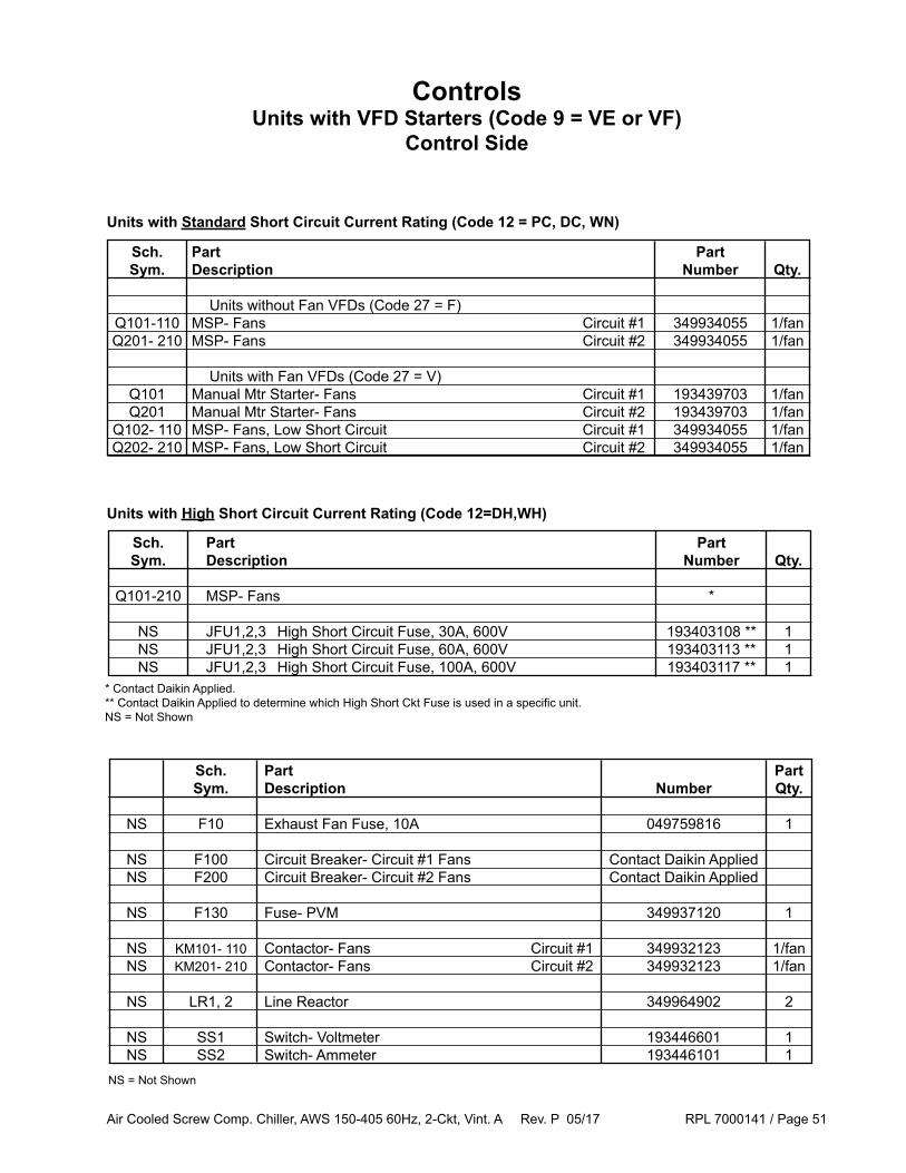
Air Cooled Screw Comp. Chiller, AWS 150-405 60Hz, 2-Ckt, Vint. A Rev. P 05/17 RPL 7000141 / Page 51
Sch. Part Part Sym. Description Number Qty.
NS F10 Exhaust Fan Fuse, 10A 049759816 1
NS F100 Circuit Breaker- Circuit #1 Fans Contact Daikin Applied NS F200 Circuit Breaker- Circuit #2 Fans Contact Daikin Applied
NS F130 Fuse- PVM 349937120 1
NS KM101- 110 Contactor- Fans Circuit #1 349932123 1/fan NS KM201- 210 Contactor- Fans Circuit #2 349932123 1/fan
NS LR1, 2 Line Reactor 349964902 2
NS SS1 Switch- Voltmeter 193446601 1 NS SS2 Switch- Ammeter 193446101 1
Sch. Part Part Sym. Description Number Qty. Units without Fan VFDs (Code 27 = F) Q101-110 MSP- Fans Circuit #1 349934055 1/fan Q201- 210 MSP- Fans Circuit #2 349934055 1/fan
Units with Fan VFDs (Code 27 = V) Q101 Manual Mtr Starter- Fans Circuit #1 193439703 1/fan Q201 Manual Mtr Starter- Fans Circuit #2 193439703 1/fan Q102- 110 MSP- Fans, Low Short Circuit Circuit #1 349934055 1/fan Q202- 210 MSP- Fans, Low Short Circuit Circuit #2 349934055 1/fan
Units with Standard Short Circuit Current Rating (Code 12 = PC, DC, WN)
Units with High Short Circuit Current Rating (Code 12=DH,WH)
ControlsUnits with VFD Starters (Code 9 = VE or VF)
Control Side
NS = Not Shown
Sch. Part Part Sym. Description Number Qty. Q101-210 MSP- Fans *
NS JFU1,2,3 High Short Circuit Fuse, 30A, 600V 193403108 ** 1 NS JFU1,2,3 High Short Circuit Fuse, 60A, 600V 193403113 ** 1 NS JFU1,2,3 High Short Circuit Fuse, 100A, 600V 193403117 ** 1 * Contact Daikin Applied. ** Contact Daikin Applied to determine which High Short Ckt Fuse is used in a specific unit.NS = Not Shown

Air Cooled Screw Comp. Chiller, AWS 150-405 60Hz, 2-Ckt, Vint. A Rev. P 05/17 RPL 7000141 / Page 52
ControlsUnits with VFD Starters (Code 9 = VE or VF)
Power Side
VFD1 VFD2
Q10 or PB1
GCT1CT4CT6
CT5
VFU1VFU2
F1, F2
T1Q12
K1F01F02

Air Cooled Screw Comp. Chiller, AWS 150-405 60Hz, 2-Ckt, Vint. A Rev. P 05/17 RPL 7000141 / Page 53
Sch. Part Part Sym. Description Number Qty. F0-1,2 Manual Motor Protector MMP/MSP, PB (Code 12= PC, DC, or WN) 349934026 2 F0-1,2 Manual Motor Protector MMP/MSP, Rotary (Code 12= DH or WH) 349934006 2
K1,2 Relay- Crankcase Heater (Code 12= PC, DC or WN) 193454201 2 K1,2 Relay- Crankcase Heater (Code 12= DH or WH) 193454301 2
Q12 Fuse- Control Transformer, 20A Non-rejection Type 349937036 1
T1 Transformer- Control, 1500VA, 380V-115V (380V units) 349992907 1 T1 Transformer- Control, 1500VA, 460V-115V (460V units) 038253957 1 T1 Transformers include the following: Finger Safe Cover for T1 349955901 Fuse Puller Kit for T1 349955801
Sch. Part Unit Efficiency Voltage Current Part Qty Sym. Description Size Code 4 Relay Number CT 4,5,6 Current Transformer 150-230 S,H,P 380V, 460V 600:5A 193432206 3 CT 4,5,6 Current Transformer 250 H 380V 600:5A 193432206 3 CT 4,5,6 Current Transformer 250 P 380V 1200:5A 193432207 3 CT 4,5,6 Current Transformer 250 H,P 460V 600:5A 193432206 3 CT 4,5,6 Current Transformer 280 H,P 380V 1200:5A 193432207 3 CT 4,5,6 Current Transformer 280 H,P 460V 600:5A 193432206 3 CT 4,5,6 Current Transformer 300-350 H,P 380V, 460V 1200:5A 193432207 3 CT 4,5,6 Current Transformer 380, 405 H 460V 1200:5A 193432207 3
Sch. Unit Part Sym. Size Number Qty Units with Single Point Pwr Blk or Disconnect (Code 12 = PC, DC or DH) GCT1 Ground Fault Current Sensor 150-300 193432203 1 GCT1 Ground Fault Current Sensor 320-405 193432205 1
Units with Multi Point Disconnect (Code 12 = WN or WH) GCT1,2,3 Ground Fault Current Sensor 150-405 193432203 3
ControlsUnits with VFD Starters (Code 9 = VE or VF)
Power Side

Air Cooled Screw Comp. Chiller, AWS 150-405 60Hz, 2-Ckt, Vint. A Rev. P 05/17 RPL 7000141 / Page 54
Unit Voltage Circuit 1 Circuit 2 Size VFD-1 VFD-2
150A 460V 193439001 193439001 150A 380V 193439002 193439002
175A 460V 193439001 193439002 175A 380V 193439002 193439003 190A 460V 193439002 193439002 190A 380V 193439003 193439003 210A 460V 193439001 193439001 210A 380V 193439002 193439002 230A 460V 193439001 193439002 230A 380V 193439002 193439003 250A 460V 193439002 193439002 250A 380V 193439003 193439003 280A 460V 193439002 193439003 280A 380V 193439003 193439004 300A 460V 193439003 193439003 300A 380V 193439004 193439004 320A 460V 193439003 193439004 320A 380V 193439004 193439005 350A 460V 193439004 193439004 350A 380V 193439005 193439005 380A 460V 193439004 193439005 380A 380V 193439005 193439006 405A 460V 193439005 193439005 405A 380V 193439006 193439006
Used with 193439001 Compressor VFD (250A) VFU1,2 Fuse- Semi-Conductor, 600A 193439601 Fuse Block- Semi-Conductor 193439501 EMI1,2 EMI Filter (Code 9 = VE) 193445701
Used with 193439002 Compressor VFD (296A) VFU1,2 Fuse- Semi-Conductor, 700A 193439602 Fuse Block- Semi-Conductor 193439501 EMI1,2 EMI Filter (Code 9 = VE) 193445702
Used with 193439003 Compressor VFD (362A) VFU1,2 Fuse- Semi-Conductor, 800A 193439603 Fuse Block- Semi-Conductor 193439501 EMI1,2 EMI Filter (Code 9 = VE) 193445702
Used with 193439004 Compressor VFD (414A) VFU1,2 Fuse- Semi-Conductor, 800A 193439603 Fuse Block- Semi-Conductor 193439501 EMI1,2 EMI Filter (Code 9 = VE) 193445702
Used with 193439005 Compressor VFD (515A) VFU1,2 Fuse- Semi-Conductor, 1000A 193439604 Fuse Block- Semi-Conductor 193439502 EMI1,2 EMI Filter (Code 9 = VE) 193445703
Used with 193439006 Compressor VFD (675A) VFU1,2 Fuse- Semi-Conductor,1200A 193439605 Fuse Block- Semi-Conductor 193439502 EMI1,2 EMI Filter (Code 9 = VE) 193445703
VFD-1, VFD-2 Compressor VFD Starter
ControlsUnits with VFD Starters (Code 9 = VE or VF)
Power Side
VFU1,2 Fuse EMI1,2 EMI Filter
Note: EMI1,2 are not shown on diagram
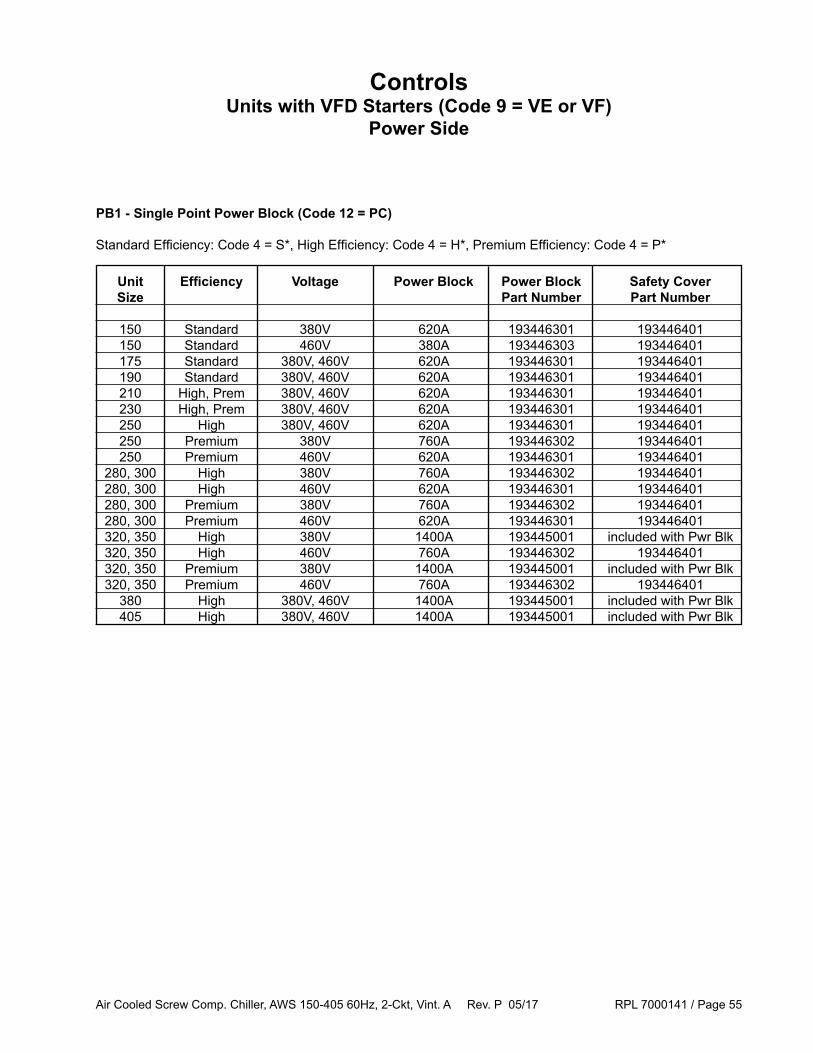
Air Cooled Screw Comp. Chiller, AWS 150-405 60Hz, 2-Ckt, Vint. A Rev. P 05/17 RPL 7000141 / Page 55
Unit Efficiency Voltage Power Block Power Block Safety Cover Size Part Number Part Number
150 Standard 380V 620A 193446301 193446401 150 Standard 460V 380A 193446303 193446401 175 Standard 380V, 460V 620A 193446301 193446401 190 Standard 380V, 460V 620A 193446301 193446401 210 High, Prem 380V, 460V 620A 193446301 193446401 230 High, Prem 380V, 460V 620A 193446301 193446401 250 High 380V, 460V 620A 193446301 193446401 250 Premium 380V 760A 193446302 193446401 250 Premium 460V 620A 193446301 193446401 280, 300 High 380V 760A 193446302 193446401 280, 300 High 460V 620A 193446301 193446401 280, 300 Premium 380V 760A 193446302 193446401 280, 300 Premium 460V 620A 193446301 193446401 320, 350 High 380V 1400A 193445001 included with Pwr Blk 320, 350 High 460V 760A 193446302 193446401 320, 350 Premium 380V 1400A 193445001 included with Pwr Blk 320, 350 Premium 460V 760A 193446302 193446401 380 High 380V, 460V 1400A 193445001 included with Pwr Blk 405 High 380V, 460V 1400A 193445001 included with Pwr Blk
PB1 - Single Point Power Block (Code 12 = PC)
ControlsUnits with VFD Starters (Code 9 = VE or VF)
Power Side
Standard Efficiency: Code 4 = S*, High Efficiency: Code 4 = H*, Premium Efficiency: Code 4 = P*
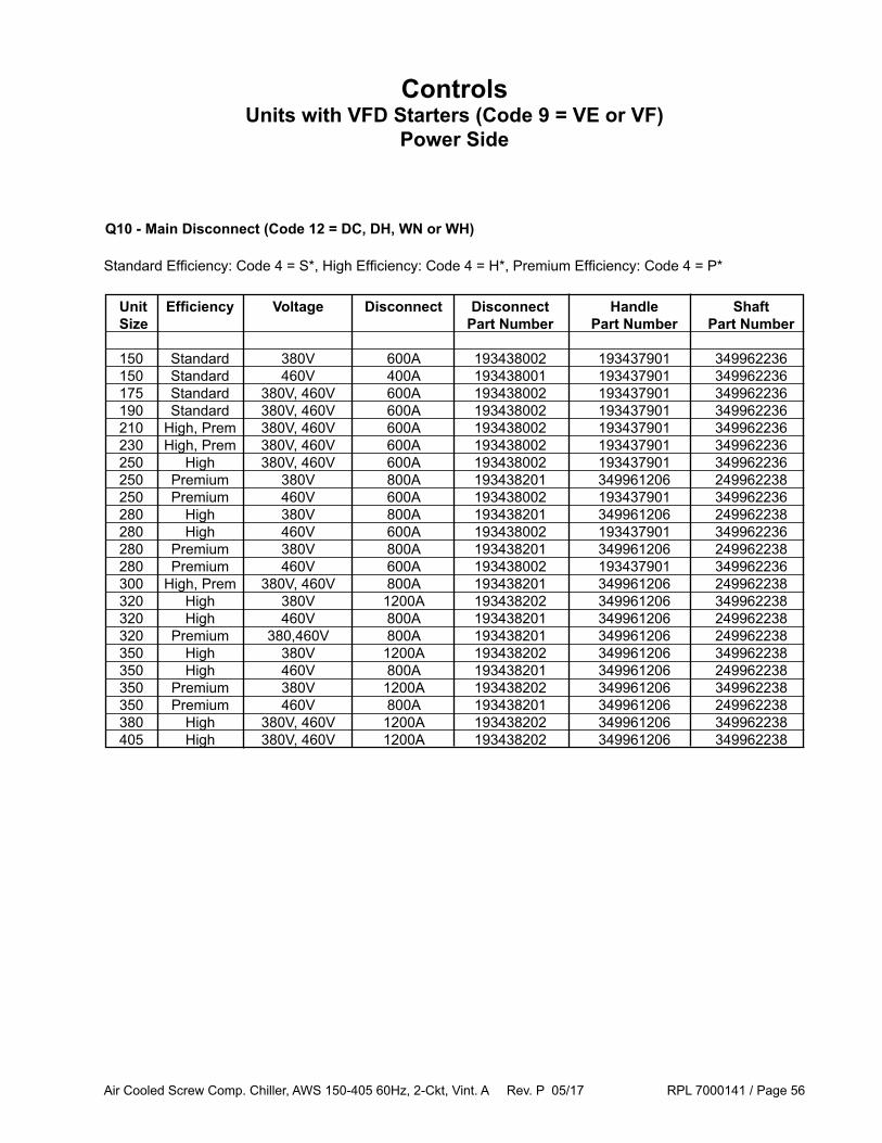
Air Cooled Screw Comp. Chiller, AWS 150-405 60Hz, 2-Ckt, Vint. A Rev. P 05/17 RPL 7000141 / Page 56
Unit Efficiency Voltage Disconnect Disconnect Handle Shaft Size Part Number Part Number Part Number
150 Standard 380V 600A 193438002 193437901 349962236 150 Standard 460V 400A 193438001 193437901 349962236 175 Standard 380V, 460V 600A 193438002 193437901 349962236 190 Standard 380V, 460V 600A 193438002 193437901 349962236 210 High, Prem 380V, 460V 600A 193438002 193437901 349962236 230 High, Prem 380V, 460V 600A 193438002 193437901 349962236 250 High 380V, 460V 600A 193438002 193437901 349962236 250 Premium 380V 800A 193438201 349961206 249962238 250 Premium 460V 600A 193438002 193437901 349962236 280 High 380V 800A 193438201 349961206 249962238 280 High 460V 600A 193438002 193437901 349962236 280 Premium 380V 800A 193438201 349961206 249962238 280 Premium 460V 600A 193438002 193437901 349962236 300 High, Prem 380V, 460V 800A 193438201 349961206 249962238 320 High 380V 1200A 193438202 349961206 349962238 320 High 460V 800A 193438201 349961206 249962238 320 Premium 380,460V 800A 193438201 349961206 249962238 350 High 380V 1200A 193438202 349961206 349962238 350 High 460V 800A 193438201 349961206 249962238 350 Premium 380V 1200A 193438202 349961206 349962238 350 Premium 460V 800A 193438201 349961206 249962238 380 High 380V, 460V 1200A 193438202 349961206 349962238 405 High 380V, 460V 1200A 193438202 349961206 349962238
ControlsUnits with VFD Starters (Code 9 = VE or VF)
Power Side
Q10 - Main Disconnect (Code 12 = DC, DH, WN or WH)
Standard Efficiency: Code 4 = S*, High Efficiency: Code 4 = H*, Premium Efficiency: Code 4 = P*

Air Cooled Screw Comp. Chiller, AWS 150-405 60Hz, 2-Ckt, Vint. A Rev. P 05/17 RPL 7000141 / Page 57
Units with Multi Point Disconnect and Standard Short Circuit Current Rating (Code 12 = WN)See next page for Multi Point Disconnect on units with High Short Circuit Current
Unit Efficiency Voltage Code 12 Molded Case Part Size Circuit Breaker Number F1 (Circuit 1) 150 Standard 380V, 460V WN 250A / 18KA 193428705 175 Standard 380V, 460V WN 250A / 18KA 193428705 190 Standard 380V WN 400A / 35KA 193454101 190 Standard 460V WN 250A / 18KA 193428705 210, 230 High,Prem 380V WN 400A / 35KA 193454101 210, 230 High,Prem 460V WN 250A / 18KA 193428705 250, 280 High,Prem 380V, 460V WN 400A / 35KA 193454101 300, 320 High,Prem 380V, 460V WN 400A / 35KA 193454101 350 High,Prem 380V WN 600A / 35KA 193454103 350 High,Prem 460V WN 400A / 35KA 193454101 380 High 460V WN 400A / 35KA 193454101 405 High 460V WN 600A / 35KA 193454103 F2 (Circuit 2) 150 Standard 380V, 460V WN 250A / 18KA 193428705 175 Standard 380V WN 400A / 35KA 193454101 175 Standard 460V WN 250A / 18KA 193428705 190 Standard 380V WN 400A / 35KA 193454101 190 Standard 460V WN 250A / 18KA 193428705 210 High,Prem 380V WN 400A / 35KA 193454101 210 High,Prem 460V WN 250A / 18KA 193428705 230, 250 High,Prem 380V, 460V WN 400A / 35KA 193454101 280, 300 High,Prem 380V, 460V WN 400A / 35KA 193454101 320, 350 High,Prem 380V WN 600A / 35KA 193454103 320, 350 High,Prem 460V WN 400A / 35KA 193454101 380, 405 High 460V WN 600A / 35KA 193454103
Handle for 250A Circuit Breaker 349935533 Handle for 400A and 600A Circuit Breaker 193437901
Shaft for 250A, 400A and 600A Circuit Breaker 349962236
ControlsUnits with VFD Starters (Code 9 = VE or VF)
Power Side
Standard Efficiency: Code 4 = S*, High Efficiency: Code 4 = H*, Premium Efficiency: Code 4 = P*

Air Cooled Screw Comp. Chiller, AWS 150-405 60Hz, 2-Ckt, Vint. A Rev. P 05/17 RPL 7000141 / Page 58
Unit Efficiency Voltage Code 12 Molded Case Part Size Circuit Breaker Number F1 (Circuit 1) 150 Standard 380V, 460V WH 250A / 65KA 193428704 175 Standard 380V, 460V WH 250A / 65KA 193428704 190 Standard 380V WH 400A / 65KA 193454102 190 Standard 460V WH 250A / 65KA 193428704 210, 230 High,Prem 380V WH 400A / 65KA 193454102 210, 230 High,Prem 460V WH 250A / 65KA 193428704 250, 280 High,Prem 380V, 460V WH 400A / 65KA 193454102 300, 320 High,Prem 380V, 460V WH 400A / 65KA 193454102 350 High,Prem 380V WH 600A / 65KA 193454104 350 High,Prem 460V WH 400A / 65KA 193454102 380 High 380V WH 600A / 65KA 193454104 380 High 460V WH 400A / 65KA 193454102 405 High 460V WH 600A / 65KA 193454104 F2 (Circuit 2) 150 Standard 380V, 460V WH 250A / 65KA 193428704 175 Standard 380V WH 400A / 65KA 193454102 175 Standard 460V WH 250A / 65KA 193428704 190 Standard 380V WH 400A / 65KA 193454102 190 Standard 460V WH 250A / 65KA 193428704 210 High,Prem 380V WH 400A / 65KA 193454102 210 High,Prem 460V WH 250A / 65KA 193428704 230, 250 High,Prem 380V, 460V WH 400A / 65KA 193454102 280, 300 High,Prem 380V, 460V WH 400A / 65KA 193454102 320, 350 High,Prem 380V WH 600A / 65KA 193454104 320, 350 High,Prem 460V WH 400A / 65KA 193454102 380 High 460V WH 600A / 65KA 193454104 405 High 460V WH 600A / 65KA 193454104
Handle for 250A Circuit Breaker 349935533 Handle for 400A and 600A Circuit Breaker 193437901
Shaft for 250A, 400A and 600A Circuit Breaker 349962236
ControlsUnits with VFD Starters (Code 9 = VE or VF)
Power Side
Units with Multi Point Disconnect and High Short Circuit Current Rating (Code 12 = WH)See previous page for Multi Point Disconnect on units with Standard Short Circuit Current
Standard Efficiency: Code 4 = S*, High Efficiency: Code 4 = H*, Premium Efficiency: Code 4 = P*

Air Cooled Screw Comp. Chiller, AWS 150-405 60Hz, 2-Ckt, Vint. A Rev. P 05/17 RPL 7000141 / Page 59
Unit Efficiency Voltage Code 12 Molded Case Part Size Circuit Breaker Number
F1 (Circuit 1) 150 Standard 380V, 460V PC, DC 250A / 18KA 193428705 175 Standard 380V, 460V PC, DC 250A / 18KA 193428705 190 Standard 380V PC, DC 400A / 30KA 193454001 190 Standard 460V PC, DC 250A / 18KA 193428705 210, 230 High,Prem 380V PC, DC 400A / 30KA 193454001 210, 230 High,Prem 460V PC, DC 250A / 18KA 193428705 250, 280, 300, 320 High,Prem 380V, 460V PC, DC 400A / 30KA 193454001 350 High,Prem 380V PC, DC 600A / 35KA 193454103 350 High,Prem 460V PC, DC 400A / 30KA 193454001 380 High 460V PC, DC 400A / 30KA 193454001 405 High 380V, 460V PC, DC 600A / 35KA 193454103 F2 (Circuit 2) 150 Standard 380V, 460V PC, DC 250A / 18KA 193428705 175, 190 Standard 380V PC, DC 400A / 30KA 193454001 175, 190 Standard 460V PC, DC 250A / 18KA 193428705 210 High,Prem 380V PC, DC 400A / 30KA 193454001 210 High,Prem 460V PC, DC 250A / 18KA 193428705 230, 250, 280, 300 High,Prem 380V, 460V PC, DC 400A / 30KA 193454001 320, 350 High,Prem 380V PC, DC 600A / 35KA 193454103 320, 350 High,Prem 460V PC, DC 400A / 30KA 193454001 380, 405 High 460V PC, DC 600A / 35KA 193454103
ControlsUnits with VFD Starters (Code 9 = VE or VF)
Power Side
Units with Single Point Circuit Breaker and Standard Short Circuit Current Rating (Code 12= PC or DC) See next page for Circuit Breaker on units with High Short Circuit Current
Standard Efficiency: Code 4 = S*, High Efficiency: Code 4 = H*, Premium Efficiency: Code 4 = P*
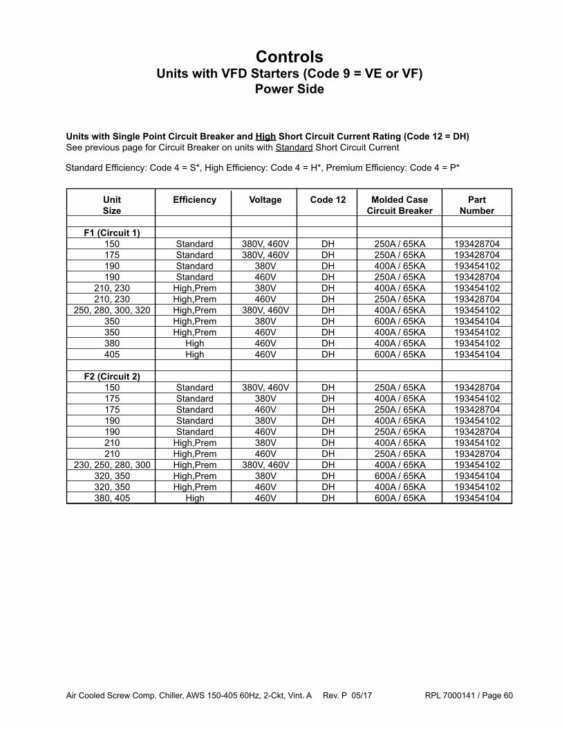
Air Cooled Screw Comp. Chiller, AWS 150-405 60Hz, 2-Ckt, Vint. A Rev. P 05/17 RPL 7000141 / Page 60
Unit Efficiency Voltage Code 12 Molded Case Part Size Circuit Breaker Number
F1 (Circuit 1) 150 Standard 380V, 460V DH 250A / 65KA 193428704 175 Standard 380V, 460V DH 250A / 65KA 193428704 190 Standard 380V DH 400A / 65KA 193454102 190 Standard 460V DH 250A / 65KA 193428704 210, 230 High,Prem 380V DH 400A / 65KA 193454102 210, 230 High,Prem 460V DH 250A / 65KA 193428704 250, 280, 300, 320 High,Prem 380V, 460V DH 400A / 65KA 193454102 350 High,Prem 380V DH 600A / 65KA 193454104 350 High,Prem 460V DH 400A / 65KA 193454102 380 High 460V DH 400A / 65KA 193454102 405 High 460V DH 600A / 65KA 193454104 F2 (Circuit 2) 150 Standard 380V, 460V DH 250A / 65KA 193428704 175 Standard 380V DH 400A / 65KA 193454102 175 Standard 460V DH 250A / 65KA 193428704 190 Standard 380V DH 400A / 65KA 193454102 190 Standard 460V DH 250A / 65KA 193428704 210 High,Prem 380V DH 400A / 65KA 193454102 210 High,Prem 460V DH 250A / 65KA 193428704 230, 250, 280, 300 High,Prem 380V, 460V DH 400A / 65KA 193454102 320, 350 High,Prem 380V DH 600A / 65KA 193454104 320, 350 High,Prem 460V DH 400A / 65KA 193454102 380, 405 High 460V DH 600A / 65KA 193454104
ControlsUnits with VFD Starters (Code 9 = VE or VF)
Power Side
Units with Single Point Circuit Breaker and High Short Circuit Current Rating (Code 12 = DH) See previous page for Circuit Breaker on units with Standard Short Circuit Current
Standard Efficiency: Code 4 = S*, High Efficiency: Code 4 = H*, Premium Efficiency: Code 4 = P*

Air Cooled Screw Comp. Chiller, AWS 150-405 60Hz, 2-Ckt, Vint. A Rev. P 05/17 RPL 7000141 / Page 61
Sch. Sym. Part Description Part Number Qty
M10 Control Box Exhaust Fan Unit sizes 150-230,300-350,405 193441002 1 M10 Control Box Exhaust Fan Unit sizes 250, 280, 380 193441003 1
M11 Control Box Intake Fan Unit sizes 300, 320, 350 193440802 1 M11 Control Box Intake Fan Unit sizes 380, 405 193440803 1
M12 Control Box Exhaust Fan Unit size 405 only 193441002 1
ControlsUnits with VFD Starters (Code 9 = VE or VF)
Control Box Exhaust and Intake Fans
M12
M10
M11

Air Cooled Screw Comp. Chiller, AWS 150-405 60Hz, 2-Ckt, Vint. A Rev. P 05/17 RPL 7000141 / Page 62
ControlsTerminal Box
Ref. Part Part No. Description Number Qty. 50 Motor Terminal Plate 330875701 1 per compressor Motor Terminal Plate Gasket 300040078 1 per compressor Motor Terminal Bolt, M8 300040079 14 per compressor Bus Bar 300044004 3 per compressor Electrical Barrier 330719201 1 per compressor Terminal Box Mounting Screw, M6 330821902 4 per compressor
61
2
34
5
Ref. Part Part No. Description Number Qty. 50 Motor Terminal Plate 131073022 1 per compressor Motor Terminal Plate Gasket 300040078 1 per compressor P3 Terminal Plate Insulator 131083020 6 per compressor Motor Terminal Bolt, M10 (Starter side) 130306091 6 per compressor Lock Washer (Starter side) 130902028 6 per compressor P4 Mounting Bolt, M8 (Plate mounting) 300040079 14 per compressor P5 Terminal Box Screw, M6 330821902 4 per compressor
Type A Terminal Plate For more information, see Parts Bulletin PB-0512-01.
Type B Terminal Plate For more information, see Parts Bulletin PB-0512-01.
50
P3
P5
P450

Air Cooled Screw Comp. Chiller, AWS 150-405 60Hz, 2-Ckt, Vint. A Rev. P 05/17 RPL 7000141 / Page 63
AccessoriesUnits with Wye-Delta or Solid State Starter (Code 9 = WD or SS)
Isolator Kits - Rubber-In-Shear
Standard Efficiency: Code 4 = S*High Efficiency: Code 4 = H*
Premium Efficiency: Code 4 = P*
Complete RIS Isolator Part #s and Quantities Group Kit 331481404 331481403 331481401 331481402 331481405 # Part # Charcoal Lime Brown Brick Red Purple 1 332325801 2 4 2 2 332325802 4 4 3 332325803 4 4 4 332325806 4 2 5 332325807 2 2 4 6 332325808 2 4 2 7 332325809 2 4 2 8 332325810 2 4 2 2 9 332325811 4 2 2 2 10 332325812 2 4 11 332325815 2 2 2 4
Total # of Fans 10 12 14 16 18 20 22 24 Units with Aluminum Fin Condenser Group # 4 4 5 1 6 6 7 8 (Code 8 = A, B, E) Units with Copper Fin Condenser Group # 10 10 1 3 2 2 10 11 (Code 8 = C, F)
Unit Std. High Prem. Unit Std. High Prem Size Eff. Eff. Eff. Size Eff. Eff. Eff. Total Total Total Total Total Total Fans Fans Fans Fans Fans Fans 175 10 -- -- 300 16 16 20 190 12 -- -- 320 20 20 22 210 12 12 16 350 20 20 24 230 14 14 18 380 -- 22 -- 250 14 14 18 405 -- 24 -- 280 16 16 20
Use the chart above to determine the Total # of Fans. Use the chart below to identify the corresponding Isolator Group #. Then, see the last chart for the Complete Kit and component part numbers.

Air Cooled Screw Comp. Chiller, AWS 150-405 60Hz, 2-Ckt, Vint. A Rev. P 05/17 RPL 7000141 / Page 64
Total # of Fans 10 12 14 16 18 20 22 24 Units with Aluminum Fin Condenser Group # 18 19 20 30 16 17 21 22 (Code 8 = A, B, E) Units with Copper Fin Condenser Group # 25 25 26 15 17 17 27 28 (Code 8 = C, F)
Standard Efficiency: Code 4 = S*High Efficiency: Code 4 = H*
Premium Efficiency: Code 4 = P*
Use the chart above to determine the Total # of Fans. Use the chart below to identify the corresponding Isolator Group #. Then, see the last chart for the Complete Kit and component part numbers.
Complete Spring Isolator Part #s and Quantities Group Kit 332620800 332620600 332620400 332620900 332620500 332621000 026219800 # Part # Dark Green Dark Purple Red Gray Black White Housing CP4 15 332320802 8 16 8 8 16 332320803 8 8 16 8 17 332320805 16 16 8 18 332320807 16 8 6 19 332320808 24 6 20 332320809 8 8 8 8 8 21 332320810 8 24 8 22 332320811 16 8 8 8 10 23 332320812 16 16 8 10 24 332320813 8 8 16 8 10 25 332320814 16 8 6 26 332320815 8 8 8 8 8 27 332320816 16 16 8 28 332320817 8 8 8 16 10 29 332320818 16 8 16 10 30 332320819 16 8 8 8
Unit Std. High Prem. Unit Std. High Prem Size Eff. Eff. Eff. Size Eff. Eff. Eff. Total Total Total Total Total Total Fans Fans Fans Fans Fans Fans 175 10 -- -- 300 16 16 20 190 12 -- -- 320 20 20 22 210 12 12 16 350 20 20 24 230 14 14 18 380 -- 22 -- 250 14 14 18 405 -- 24 -- 280 16 16 20
AccessoriesUnits with Wye-Delta or Solid State Starter (Code 9 = WD or SS)
Isolator Kits - Spring

Air Cooled Screw Comp. Chiller, AWS 150-405 60Hz, 2-Ckt, Vint. A Rev. P 05/17 RPL 7000141 / Page 65
Total # of Fans 10 12 14 16 18 20 22 24 Units with Aluminum Fin Condenser Group # 35 35 36 36 37 37 37 38 (Code 8 = A, B, E) Units with Copper Fin Condenser Group # 40 40 37 37 37 37 37 38 (Code 8 = C, F)
AccessoriesUnits with VFD Starter (Code 9 = VF or VE)
Isolator Kits - Rubber-In-Shear
Standard Efficiency: Code 4 = S*High Efficiency: Code 4 = H*
Premium Efficiency: Code 4 = P*
Complete RIS Isolator Part #s and Quantities Group Kit 331481403 331481402 # Part # Lime Brick Red 35 332325821 8 36 332325822 10 37 332325823 10 38 332325824 12 40 332325826 8
Use the chart above to determine the Total # of Fans. Use the chart below to identify the corresponding Isolator Group #. Then, see the last chart for the Complete Kit and component part numbers.
Unit Std. High Prem. Size Eff. Eff. Eff. Total Total Total Fans Fans Fans 150 10 -- -- 175 12 -- -- 190 12 -- -- 210 -- 12 16 230 -- 14 18 250 -- 14 18 280 -- 16 20 300 -- 16 20 320 -- 20 22 350 -- 20 24 380 -- 22 -- 405 -- 24 --
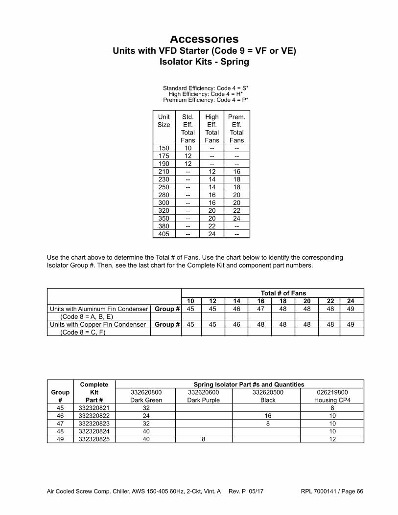
Air Cooled Screw Comp. Chiller, AWS 150-405 60Hz, 2-Ckt, Vint. A Rev. P 05/17 RPL 7000141 / Page 66
Complete Spring Isolator Part #s and Quantities Group Kit 332620800 332620600 332620500 026219800 # Part # Dark Green Dark Purple Black Housing CP4 45 332320821 32 8 46 332320822 24 16 10 47 332320823 32 8 10 48 332320824 40 10 49 332320825 40 8 12
Total # of Fans 10 12 14 16 18 20 22 24 Units with Aluminum Fin Condenser Group # 45 45 46 47 48 48 48 49 (Code 8 = A, B, E) Units with Copper Fin Condenser Group # 45 45 46 48 48 48 48 49 (Code 8 = C, F)
AccessoriesUnits with VFD Starter (Code 9 = VF or VE)
Isolator Kits - Spring
Use the chart above to determine the Total # of Fans. Use the chart below to identify the corresponding Isolator Group #. Then, see the last chart for the Complete Kit and component part numbers.
Standard Efficiency: Code 4 = S*High Efficiency: Code 4 = H*
Premium Efficiency: Code 4 = P*
Unit Std. High Prem. Size Eff. Eff. Eff. Total Total Total Fans Fans Fans 150 10 -- -- 175 12 -- -- 190 12 -- -- 210 -- 12 16 230 -- 14 18 250 -- 14 18 280 -- 16 20 300 -- 16 20 320 -- 20 22 350 -- 20 24 380 -- 22 -- 405 -- 24 --
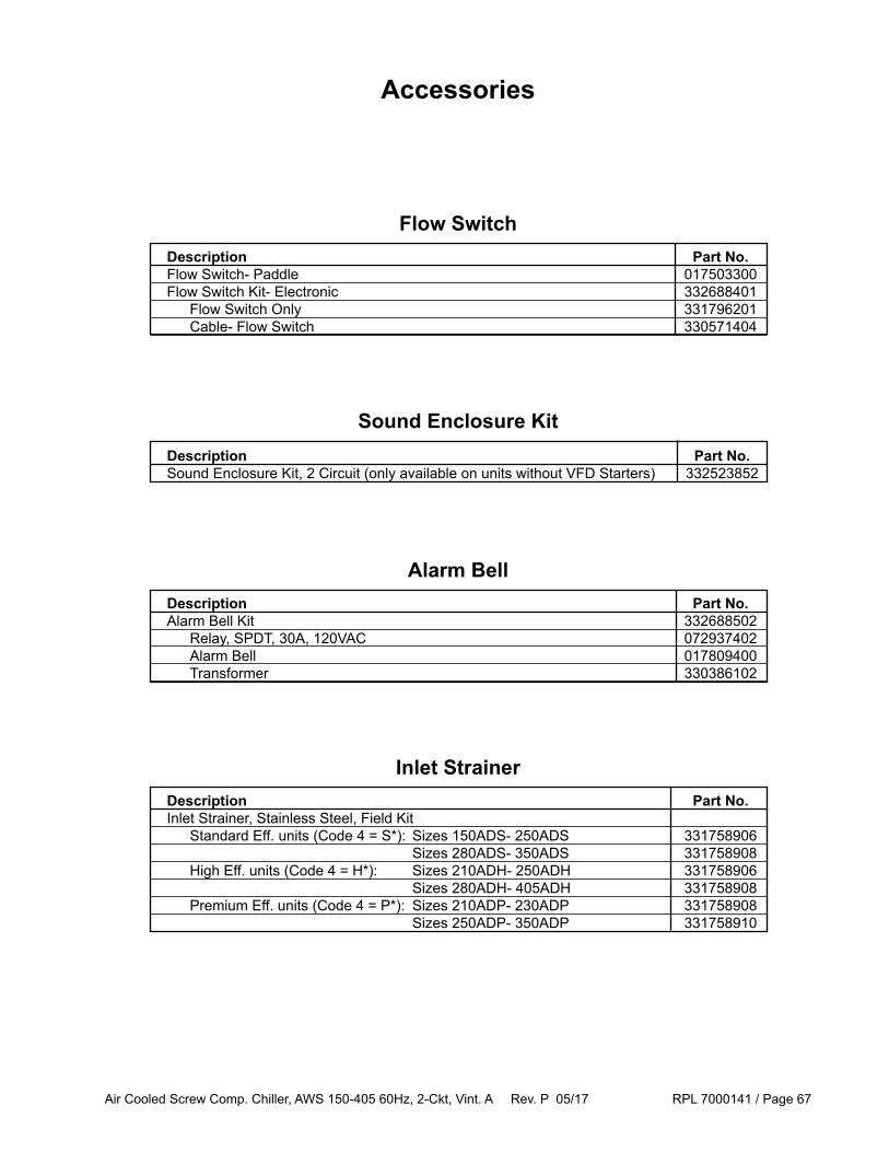
Air Cooled Screw Comp. Chiller, AWS 150-405 60Hz, 2-Ckt, Vint. A Rev. P 05/17 RPL 7000141 / Page 67
Accessories
Flow Switch Description Part No. Flow Switch- Paddle 017503300 Flow Switch Kit- Electronic 332688401 Flow Switch Only 331796201 Cable- Flow Switch 330571404
Sound Enclosure Kit Description Part No. Sound Enclosure Kit, 2 Circuit (only available on units without VFD Starters) 332523852
Alarm Bell Description Part No. Alarm Bell Kit 332688502 Relay, SPDT, 30A, 120VAC 072937402 Alarm Bell 017809400 Transformer 330386102
Inlet Strainer Description Part No. Inlet Strainer, Stainless Steel, Field Kit Standard Eff. units (Code 4 = S*): Sizes 150ADS- 250ADS 331758906 Sizes 280ADS- 350ADS 331758908 High Eff. units (Code 4 = H*): Sizes 210ADH- 250ADH 331758906 Sizes 280ADH- 405ADH 331758908 Premium Eff. units (Code 4 = P*): Sizes 210ADP- 230ADP 331758908 Sizes 250ADP- 350ADP 331758910
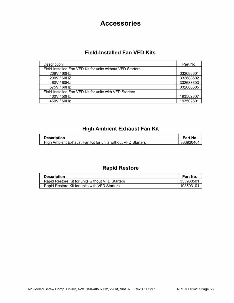
Air Cooled Screw Comp. Chiller, AWS 150-405 60Hz, 2-Ckt, Vint. A Rev. P 05/17 RPL 7000141 / Page 68
Accessories
High Ambient Exhaust Fan Kit Description Part No. High Ambient Exhaust Fan Kit for units without VFD Starters 333930401
Rapid Restore Description Part No. Rapid Restore Kit for units without VFD Starters 333930501 Rapid Restore Kit for units with VFD Starters 193503101
Field-Installed Fan VFD Kits
Description Part No. Field-Installed Fan VFD Kit for units without VFD Starters 208V / 60Hz 332688601 230V / 60HZ 332688602 460V / 60Hz 332688603 575V / 60Hz 332688605 Field-Installed Fan VFD Kit for units with VFD Starters 400V / 50Hz 193502807 460V / 60Hz 193502801

Air Cooled Screw Comp. Chiller, AWS 150-405 60Hz, 2-Ckt, Vint. A Rev. P 05/17 RPL 7000141 / Page 69
Base Grille Kits* - Units with Wye-Delta or SS Starter (Code 8 = WD, SS) Total # of Fans 10 12 14 16 18 20 22 24 332688110 332688112 332688114 332688116 332688118 332688120 332688122 332688124
Base Grille Kits* - Units with VFD Starter (Code 8 = VF, VE)
* Kit part numbers above include Grilles and hardware. For component details, see earlier pages concerning Coil and Base Frame Grilles and Louvers.
Total # of Fans 10 12 14 16 18 20 22 24 332688148 332688135 332688136 332688137 332688138 332688139 332688140 332688141
Coil Louver Kits**
Total # of Fans 10 12 14 16 18 20 22 24 332688210 332688212 332688214 332688216 332688218 332688220 332688222 332688224
Base & Coil Louver Kits**- Units with Wye-Delta or SS Starter (Code 8 = WD, SS)
Total # of Fans 10 12 14 16 18 20 22 24 332688310 332688312 332688314 332688316 332688318 332688320 332688322 332688324
Base & Coil Louver Kits** - Units with VFD Starter (Code 8 = VF, VE)
** Kit part numbers above include Louvers and hardware. For component details, see earlier pages concerning Coil and Base Frame Grilles and Louvers.
Total # of Fans 10 12 14 16 18 20 22 24 332688348 332688335 332688336 332688337 332688338 332688339 332688340 332688341
Standard Efficiency: Code 4 = S*, High Efficiency: Code 4 = H*, Premium Efficiency: Code 4 = P*
AccessoriesBase and Coil - Grille and Louver Kits
Unit Std. High Prem. Size Eff. Eff. Eff. Total Total Total Fans Fans Fans 150 10 -- -- 175 12 -- -- 190 12 -- -- 210 -- 12 16 230 -- 14 18 250 -- 14 18
Unit Std. High Prem. Size Eff. Eff. Eff. Total Total Total Fans Fans Fans 280 -- 16 20 300 -- 16 20 320 -- 20 22 350 -- 20 24 380 -- 22 -- 405 -- 24 --
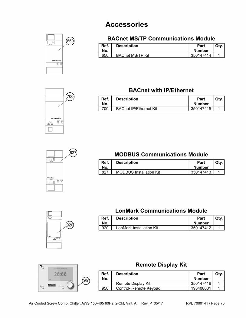
Air Cooled Screw Comp. Chiller, AWS 150-405 60Hz, 2-Ckt, Vint. A Rev. P 05/17 RPL 7000141 / Page 70
Ref. Description Part Qty. No. Number Remote Display Kit 350147416 1 950 Control- Remote Keypad 193408001 1
BACnet with IP/Ethernet
Ref. Description Part Qty. No. Number 827 MODBUS Installation Kit 350147413 1
MODBUS Communications Module
Ref. Description Part Qty. No. Number 920 LonMark Installation Kit 350147412 1
LonMark Communications Module
Accessories
Ref. Description Part Qty. No. Number 650 BACnet MS/TP Kit 350147414 1
BACnet MS/TP Communications Module
Remote Display Kit
Ref. Description Part Qty. No. Number 700 BACnet IP/Ethernet Kit 350147415 1
827
700
650
920
950