Embed Size (px)
Citation preview
Slide 1
Path Calculation and Setup
Sources: MPLS Forum
V. Alwayn, Advanced MPLS Design and Implementation, Cisco Press E. W. Gray, MPLS Implementing the Technology, Addison Wesley
B. Davie and Y. Rekhter, MPLS Technology and Applications, Morgan Kaufmann E. Osborne and A. Simha, Traffic Engineering with MPLS, Cisco Press
Slide 2
MPLS TE
• How does MPLS TE really work? • What are the underlying protocols and algorithms? • How do they all tie together?
• MPLS TE can be broken into three paths: Information distribution Path calculation and setup Forwarding traffic down a tunnel
Slide 3
What to cover?
• Path Calculation: Basic Shortest Path First (SPF) calculation to build routing
tables in an IP network MPLS TE’s Constrained SPF (CSPF) and how it differs from
the SPF performed by IP routing protocols Mechanisms can be used to influence CSPF’s path
calculation
• LSP setup / teardown and signalling: RSVP-TE CR-LDP
Slide 4
What to cover?
• Path Calculation • Path Setup
Slide 5
How SPF Works?
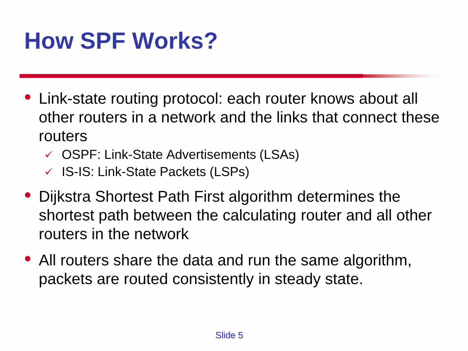
• Link-state routing protocol: each router knows about all other routers in a network and the links that connect these routers OSPF: Link-State Advertisements (LSAs) IS-IS: Link-State Packets (LSPs)
• Dijkstra Shortest Path First algorithm determines the shortest path between the calculating router and all other routers in the network
• All routers share the data and run the same algorithm, packets are routed consistently in steady state.
Slide 6
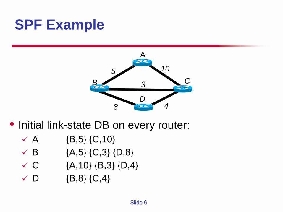
SPF Example
• Initial link-state DB on every router: A {B,5} {C,10} B {A,5} {C,3} {D,8} C {A,10} {B,3} {D,4} D {B,8} {C,4}
A
B
D
C 5
3
10
8 4
Slide 7
What To Do with the Information?
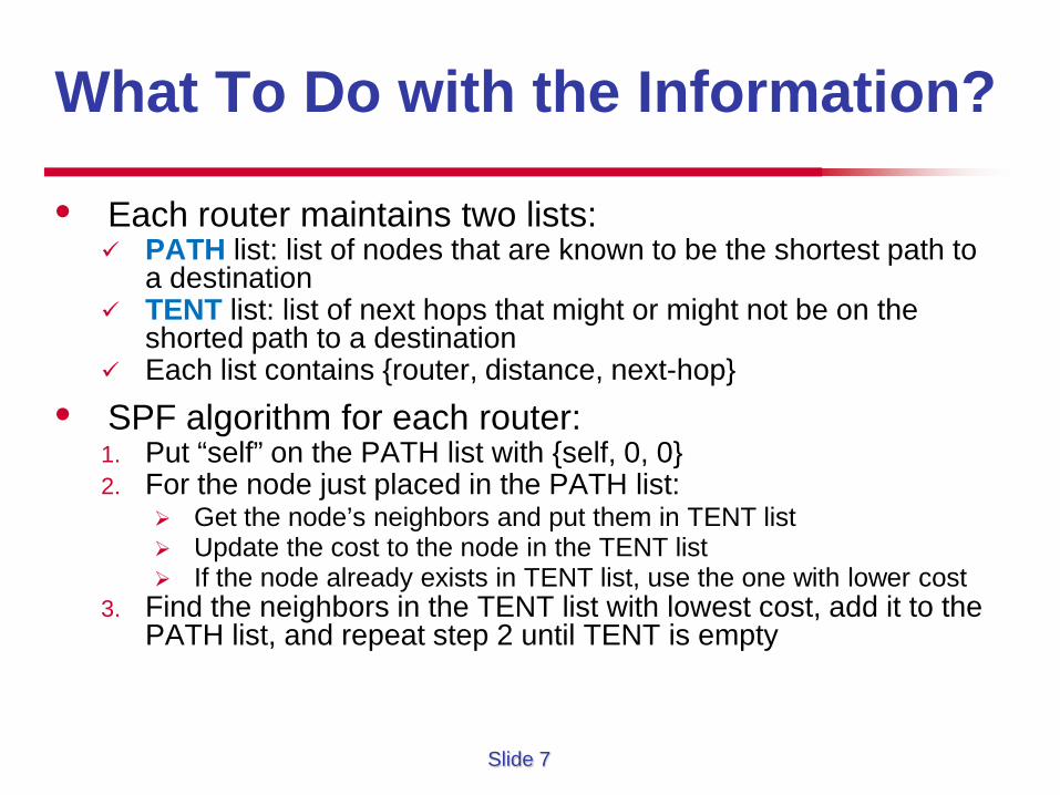
• Each router maintains two lists: PATH list: list of nodes that are known to be the shortest path to
a destination TENT list: list of next hops that might or might not be on the
shorted path to a destination Each list contains {router, distance, next-hop}
• SPF algorithm for each router: 1. Put “self” on the PATH list with {self, 0, 0} 2. For the node just placed in the PATH list:
Get the node’s neighbors and put them in TENT list Update the cost to the node in the TENT list If the node already exists in TENT list, use the one with lower cost
3. Find the neighbors in the TENT list with lowest cost, add it to the PATH list, and repeat step 2 until TENT is empty
Slide 8
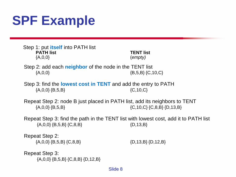
Step 1: put itself into PATH list PATH list TENT list {A,0,0} (empty)
Step 2: add each neighbor of the node in the TENT list {A,0,0} {B,5,B} {C,10,C} Step 3: find the lowest cost in TENT and add the entry to PATH {A,0,0} {B,5,B} {C,10,C} Repeat Step 2: node B just placed in PATH list, add its neighbors to TENT {A,0,0} {B,5,B} {C,10,C} {C,8,B} {D,13,B} Repeat Step 3: find the path in the TENT list with lowest cost, add it to PATH list {A,0,0} {B,5,B} {C,8,B} {D,13,B} Repeat Step 2: {A,0,0} {B,5,B} {C,8,B} {D,13,B} {D,12,B} Repeat Step 3: {A,0,0} {B,5,B} {C,8,B} {D,12,B}
SPF Example
Slide 9
SPF Example
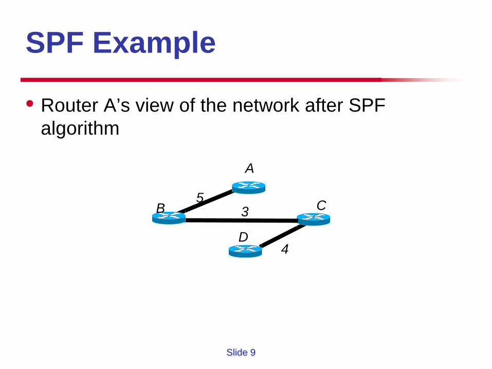
• Router A’s view of the network after SPF algorithm
B
D
C 5 3
4
A
Slide 10
Constrained SPF (CSPF)
• Two main differences between SPF and CSPF LSP or tunnel determination process not designed to find
the best route to all routers – only the tunnel endpoint. More than one metric at each node. Typical information
related to TE: Bandwidth Link attributes Administrative weight
• So, Triplet becomes sextuplet, including the above 3 metrics Need tiebreakers if two paths have the same value
Slide 11
CSPF Example
B
D
C 5, 100
3, 50
10, 100 (cost, bandwidth)
8, 90 4, 60
A
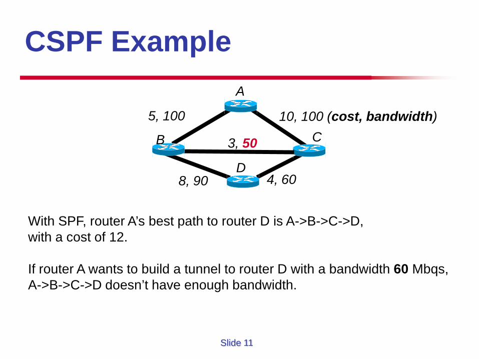
With SPF, router A’s best path to router D is A->B->C->D, with a cost of 12. If router A wants to build a tunnel to router D with a bandwidth 60 Mbqs, A->B->C->D doesn’t have enough bandwidth.
Slide 12
How Does CSPF Work?
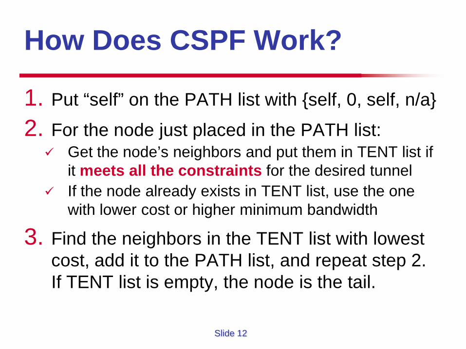
1. Put “self” on the PATH list with {self, 0, self, n/a}
2. For the node just placed in the PATH list: Get the node’s neighbors and put them in TENT list if
it meets all the constraints for the desired tunnel If the node already exists in TENT list, use the one
with lower cost or higher minimum bandwidth
3. Find the neighbors in the TENT list with lowest cost, add it to the PATH list, and repeat step 2. If TENT list is empty, the node is the tail.
Slide 13
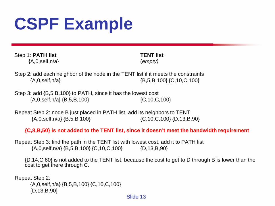
CSPF Example Step 1: PATH list TENT list
{A,0,self,n/a} (empty) Step 2: add each neighbor of the node in the TENT list if it meets the constraints {A,0,self,n/a} {B,5,B,100} {C,10,C,100} Step 3: add {B,5,B,100} to PATH, since it has the lowest cost {A,0,self,n/a} {B,5,B,100} {C,10,C,100} Repeat Step 2: node B just placed in PATH list, add its neighbors to TENT {A,0,self,n/a} {B,5,B,100} {C,10,C,100} {D,13,B,90}
{C,8,B,50} is not added to the TENT list, since it doesn’t meet the bandwidth requirement
Repeat Step 3: find the path in the TENT list with lowest cost, add it to PATH list {A,0,self,n/a} {B,5,B,100} {C,10,C,100} {D,13,B,90}
{D,14,C,60} is not added to the TENT list, because the cost to get to D through B is lower than the
cost to get there through C. Repeat Step 2: {A,0,self,n/a} {B,5,B,100} {C,10,C,100} {D,13,B,90}
Slide 14
Tiebreakers in CSPF
• In regular SPF, Equal-Cost Multipath (ECMP) can be used for multiple paths with the same cost Issues and limitations of ECMP?
• In CSPF, we are looking for one path to one destination. We need tiebreakers for this case. Take the path with the largest available bandwidth If there is still a tie, take the path with the lowest hop
count If there is still a tie, take one at random (usually the
first one) Example
Slide 15
Other Factors for CSPF • Other than bandwidth, link attributes, and administrative weight, another
important attribute is delay, primarily for voice application or financial information networks
• One approach is to manipulate IGP link metric to represent delay rather than bandwidth. But will lose the ability to accurately route traffic, which can have serious impact.
• MPLS TE can consider both link bw and delay: Example: high-bandwidth, high-latency vs. low-bandwidth, low-latency path? Use administrative weight to configure the link delay
• It’s hard to determine the amount of end-to-end (E2E) latency across a particular circuit. Some ways can be used: Ping from one router to another across a circuit. Problems? Determine the expected latency based on route-miles. Errors? Use Service Assurance Agent or Akamai server to determine the latency OSPF TE Metric Extensions (last updated Dec., 2012) for each link
Slide 16
Explicit Path Setup
• Explicit routing (ER) is a key feature for MPLS. What is ER?
• Explicit paths are usually a series of next addresses that list router hops (either TE router ID or i/f addresses) in the order you want the tunnel to traverse them. Strict source route Loose source route Exclude option allows the user to specify a list of links or
nodes not to be used in the path calculation Useful in TE
• Difference between explicit routing and source routing?
Slide 17
Tunnel Reoptimization • Reoptimization: a router looks to see if there is a better
path for tunnels that are already up. Not for explicit path. • If an event happens:
How long should a router wait before cutting over to the best path?
How to reoptimize an existing tunnel? How about other existing tunnels that share some nodes/links?
• Four factors affecting reoptimization: Periodic reoptimization for a tunnel that’s up for X minutes Manual reoptimization up to the operator Event-driven reoptimization: link up/down, but need to avoid it if
the link is flapping Lockdown: disable reoptimization unless a link goes down
Slide 18
What to Cover?
• Path Calculation • Path Setup Signalling protocols: LSP setup / teardown and
signalling: RSVP-TE CR-LDP (only briefly)
Slide 19
Signaling Protocols
• After a path is calculated or explicitly selected, that path needs to be signaled across the network To establish a hop-by-hop chain of labels that
represent the path To reserve consumable resources (bandwidth) across
the path (optional) To maintain the state of the path The is accomplished by signaling protocols
Slide 20
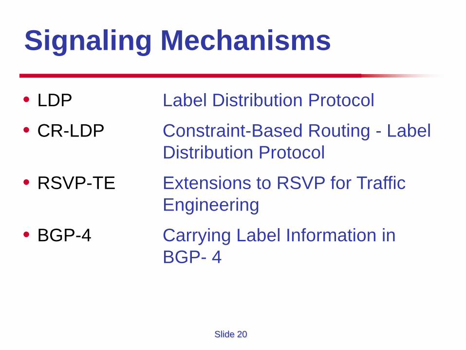
• LDP Label Distribution Protocol
• CR-LDP Constraint-Based Routing - Label Distribution Protocol
• RSVP-TE Extensions to RSVP for Traffic Engineering
• BGP-4 Carrying Label Information in BGP- 4
Signaling Mechanisms
Slide 21
Constraint-Based Routing Label Distribution Protocol
CR - LDP
Slide 22
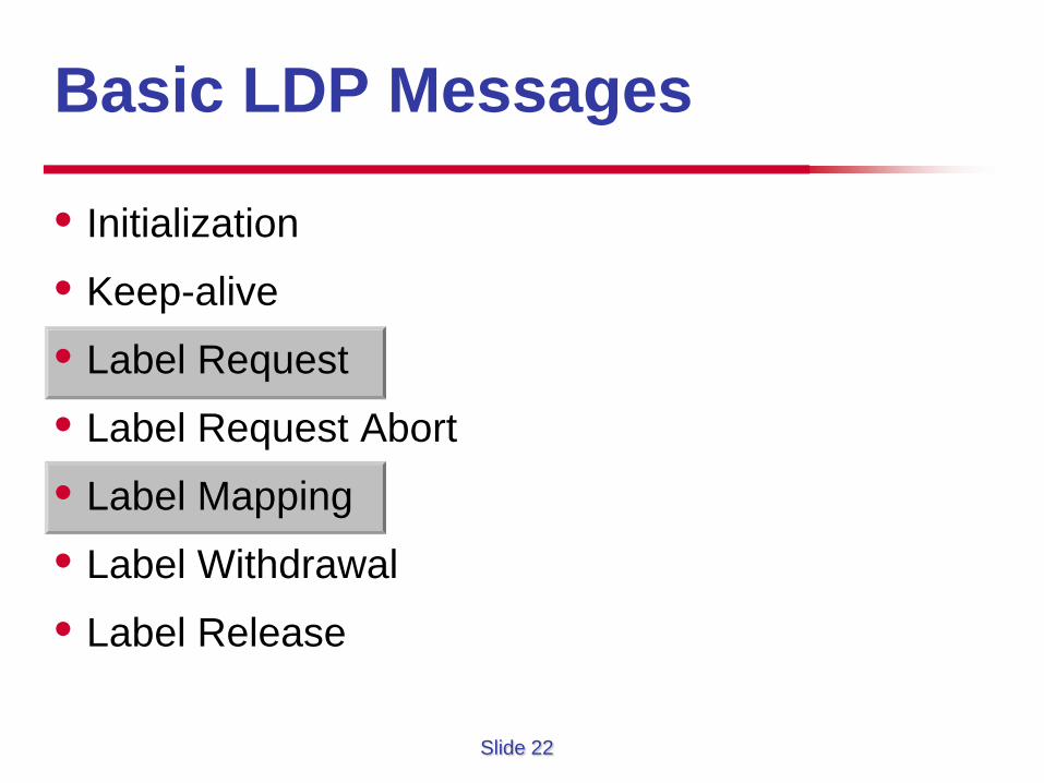
• Initialization
• Keep-alive
• Label Request
• Label Request Abort
• Label Mapping
• Label Withdrawal
• Label Release
Basic LDP Messages
Slide 23
CR – LDP Constraint-Based Routing - Label Distribution Protocol
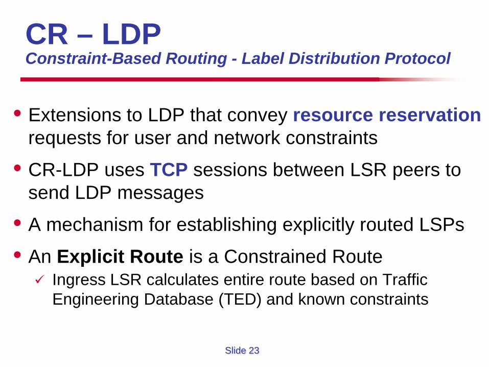
• Extensions to LDP that convey resource reservation requests for user and network constraints
• CR-LDP uses TCP sessions between LSR peers to send LDP messages
• A mechanism for establishing explicitly routed LSPs
• An Explicit Route is a Constrained Route Ingress LSR calculates entire route based on Traffic
Engineering Database (TED) and known constraints
Slide 24
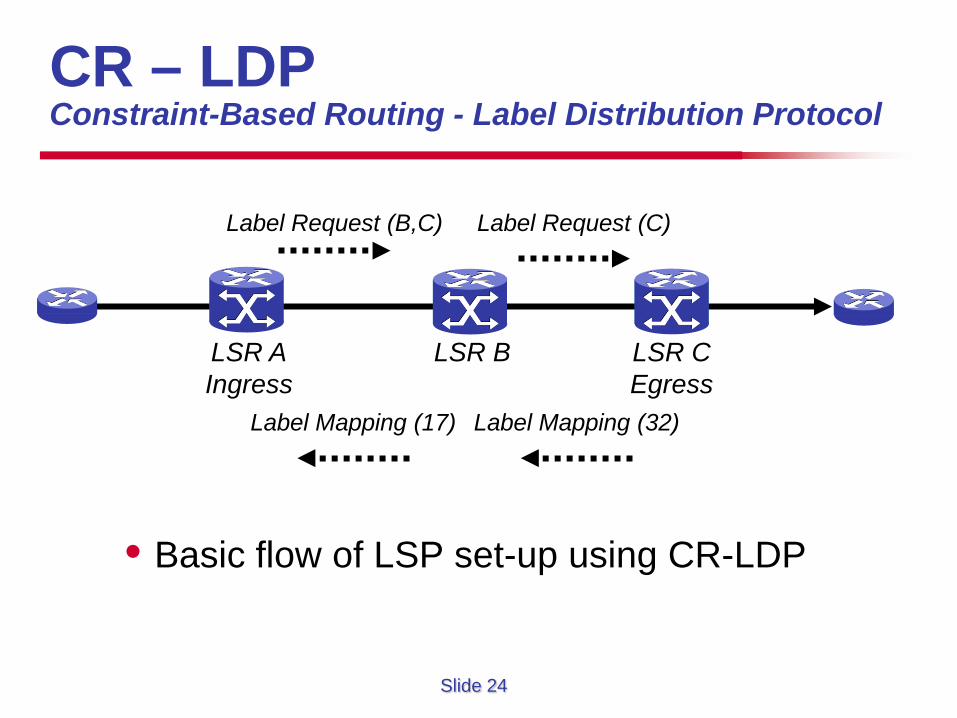
CR – LDP Constraint-Based Routing - Label Distribution Protocol
• Basic flow of LSP set-up using CR-LDP
Label Request (B,C)
LSR C Egress
LSR B LSR A Ingress
Label Request (C)
Label Mapping (32) Label Mapping (17)
Slide 25
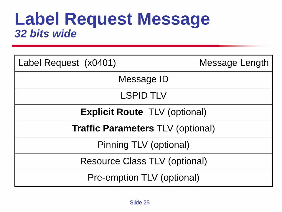
Label Request Message 32 bits wide
Label Request (x0401) Message Length
Message ID
LSPID TLV
Explicit Route TLV (optional)
Traffic Parameters TLV (optional)
Pinning TLV (optional)
Resource Class TLV (optional)
Pre-emption TLV (optional)
Slide 26
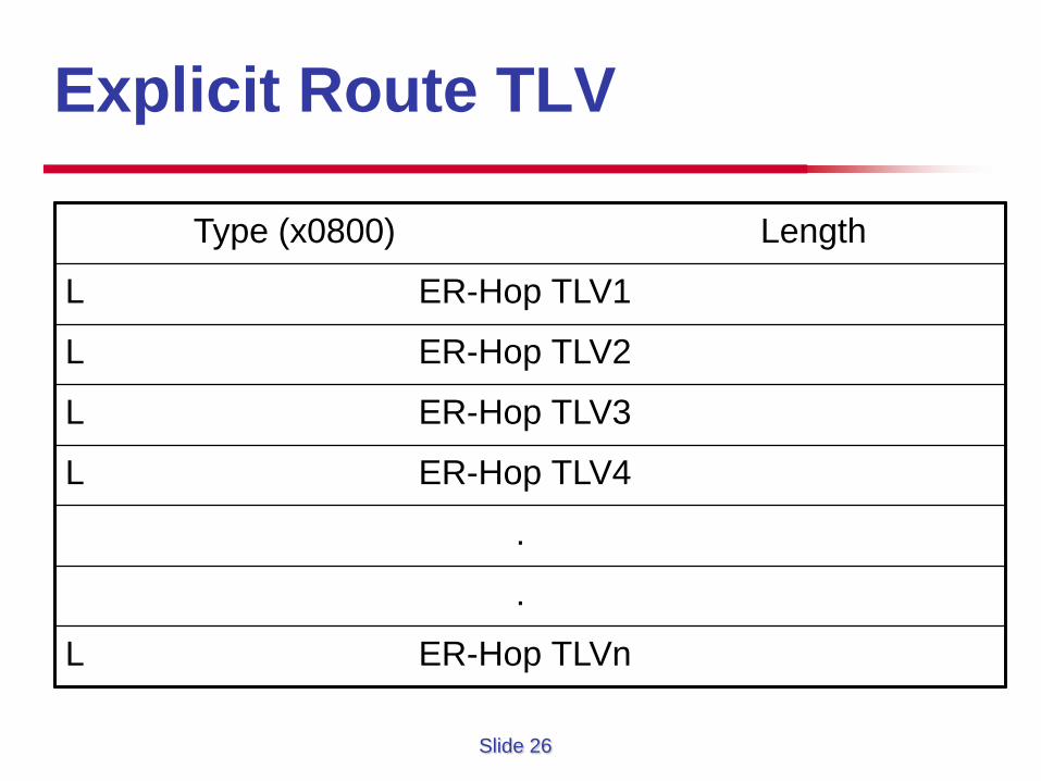
Explicit Route TLV
Type (x0800) Length
L ER-Hop TLV1
L ER-Hop TLV2
L ER-Hop TLV3
L ER-Hop TLV4
.
.
L ER-Hop TLVn
Slide 27
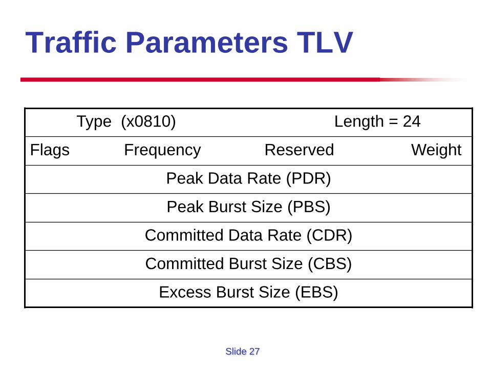
Traffic Parameters TLV
Type (x0810) Length = 24
Flags Frequency Reserved Weight
Peak Data Rate (PDR)
Peak Burst Size (PBS)
Committed Data Rate (CDR)
Committed Burst Size (CBS)
Excess Burst Size (EBS)
Slide 28
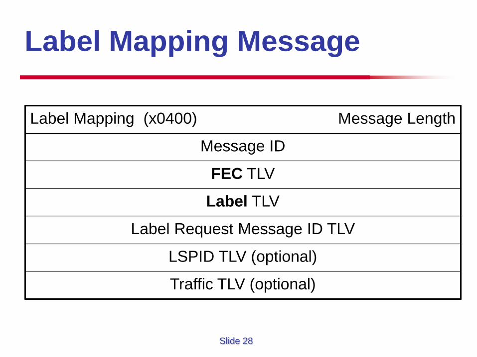
Label Mapping Message
Label Mapping (x0400) Message Length
Message ID
FEC TLV
Label TLV
Label Request Message ID TLV
LSPID TLV (optional)
Traffic TLV (optional)
Slide 29
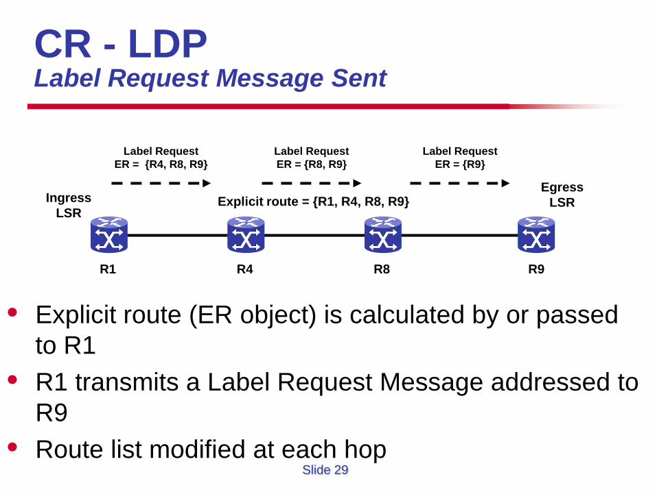
CR - LDP Label Request Message Sent
• Explicit route (ER object) is calculated by or passed to R1
• R1 transmits a Label Request Message addressed to R9
• Route list modified at each hop
R1 R4 R8 R9
Ingress LSR
Egress LSR Explicit route = {R1, R4, R8, R9}
Label Request ER = {R4, R8, R9}
Label Request ER = {R8, R9}
Label Request ER = {R9}
Slide 30
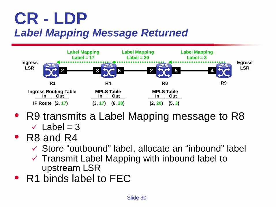
CR - LDP Label Mapping Message Returned
• R9 transmits a Label Mapping message to R8 Label = 3
• R8 and R4 Store “outbound” label, allocate an “inbound” label Transmit Label Mapping with inbound label to
upstream LSR • R1 binds label to FEC
R1 R4 R8
Ingress LSR
Egress LSR 3 6 2 5 4 2
R9
Label Mapping Label = 3
Label Mapping Label = 20
Label Mapping Label = 17
MPLS Table In Out
(5, 3) (2, 20) In Out
MPLS Table
(6, 20) (3, 17)
Ingress Routing Table In Out
(2, 17) IP Route
Slide 31
Resource Reservation Protocol with Traffic Engineering
RSVP-TE
Slide 32
RSVP –TE RSVP with Traffic Engineering Extensions
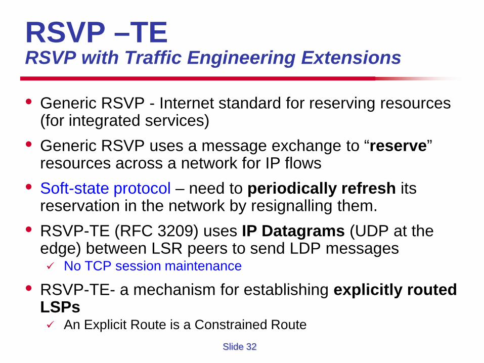
• Generic RSVP - Internet standard for reserving resources (for integrated services)
• Generic RSVP uses a message exchange to “reserve” resources across a network for IP flows
• Soft-state protocol – need to periodically refresh its reservation in the network by resignalling them.
• RSVP-TE (RFC 3209) uses IP Datagrams (UDP at the edge) between LSR peers to send LDP messages No TCP session maintenance
• RSVP-TE- a mechanism for establishing explicitly routed LSPs An Explicit Route is a Constrained Route
Slide 33
RSVP Basic Functions
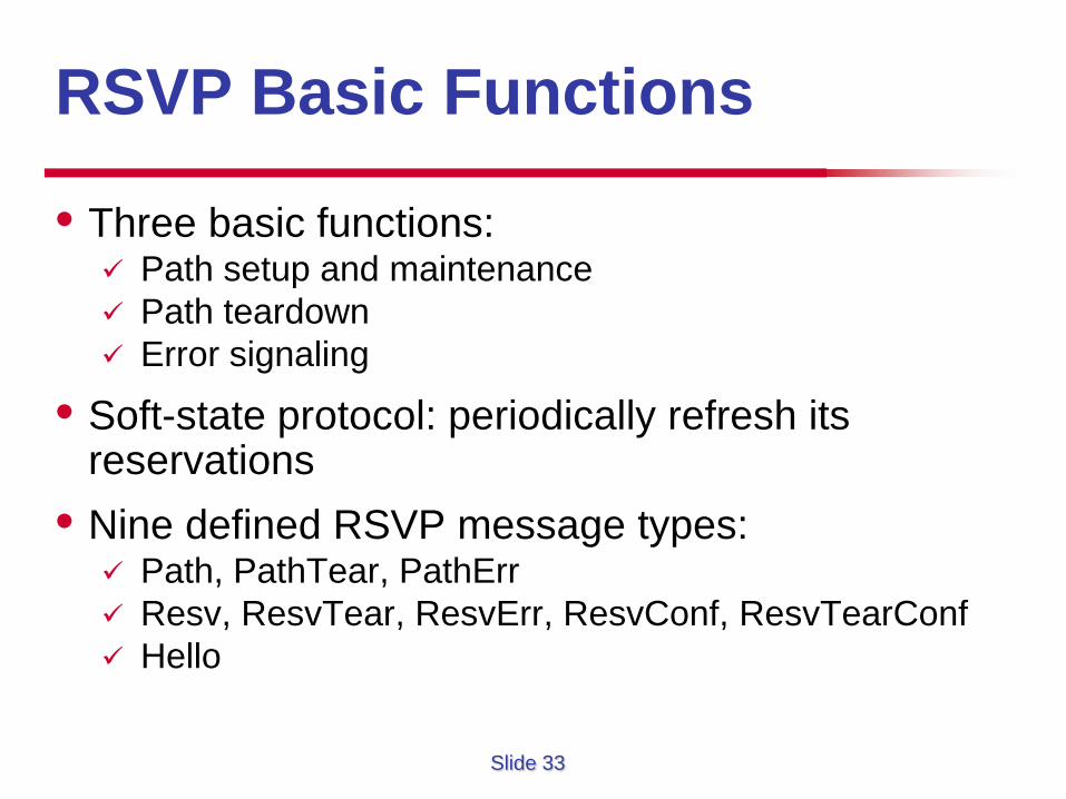
• Three basic functions: Path setup and maintenance Path teardown Error signaling
• Soft-state protocol: periodically refresh its reservations
• Nine defined RSVP message types: Path, PathTear, PathErr Resv, ResvTear, ResvErr, ResvConf, ResvTearConf Hello
Slide 34
RSVP –TE RSVP with Traffic Engineering Extensions
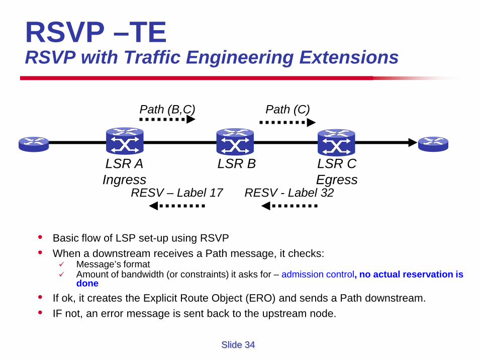
• Basic flow of LSP set-up using RSVP • When a downstream receives a Path message, it checks:
Message’s format Amount of bandwidth (or constraints) it asks for – admission control, no actual reservation is
done • If ok, it creates the Explicit Route Object (ERO) and sends a Path downstream. • IF not, an error message is sent back to the upstream node.
Path (B,C)
LSR C Egress
LSR B LSR A Ingress
Path (C)
RESV - Label 32 RESV – Label 17
Slide 35
Path Setup
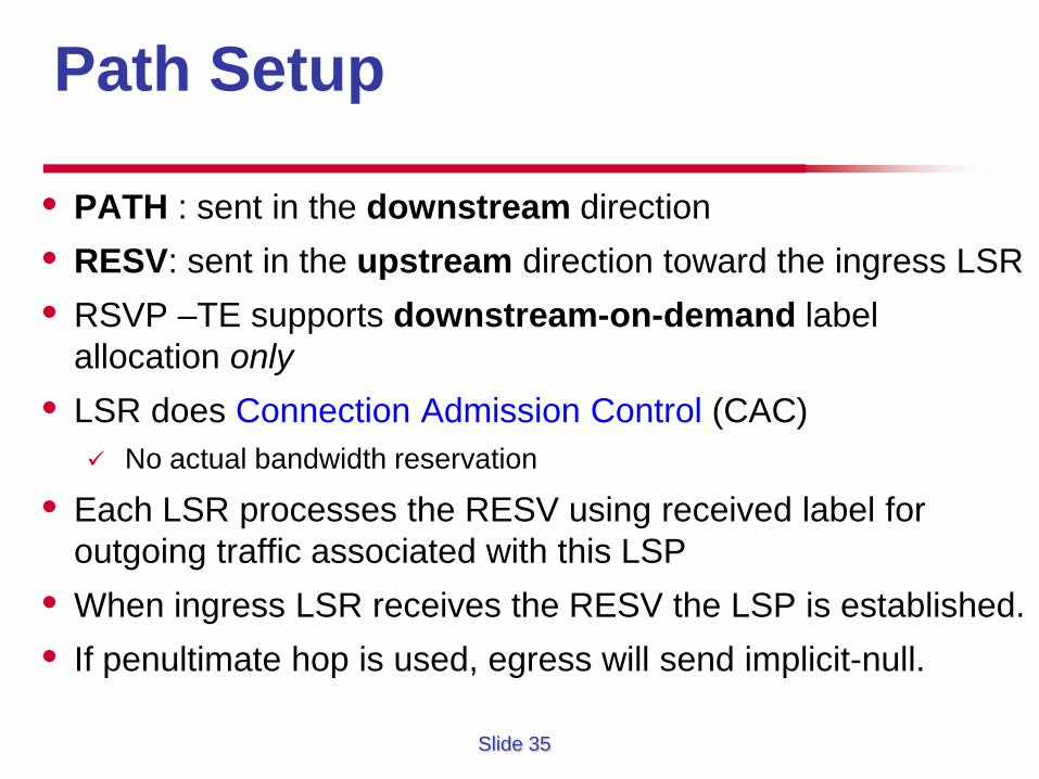
• PATH : sent in the downstream direction • RESV: sent in the upstream direction toward the ingress LSR • RSVP –TE supports downstream-on-demand label
allocation only • LSR does Connection Admission Control (CAC)
No actual bandwidth reservation
• Each LSR processes the RESV using received label for outgoing traffic associated with this LSP
• When ingress LSR receives the RESV the LSP is established. • If penultimate hop is used, egress will send implicit-null.
Slide 36
Path Maintenance • A headend sends on Path message per tunnel to its
downstream nodes every 30 seconds +/- 50%.
• If a router sends out 4 Path messages in a row and does not receive a Resv message during that time, it considers the reservation down and notifies its upstream nodes that the reservation is gone.
• Path and Resv maintenance messages are both send independently and asynchronously from one neighbor to another.
• Resv is used to refresh an existing reservation, not a response to a Path message in terms of maintenance.
Slide 37
Path Teardown • If the headend (ingress) decides that a reservation is
no longer needed or due to an error, it sends a PathTear along the same path.
• ResvTear is sent in response to PathTear: the downstream node has removed the reservation.
• PathTear messages don’t have to go all the way downstream before taking effect.
• RSVP message pacing: If a link flaps, a PathErr/ResvErr needs to be sent for every
tunnel on that link. What if the number of tunnels is large, e.g., 2000, 3000?
Control the rate of RSVP messages
Slide 38
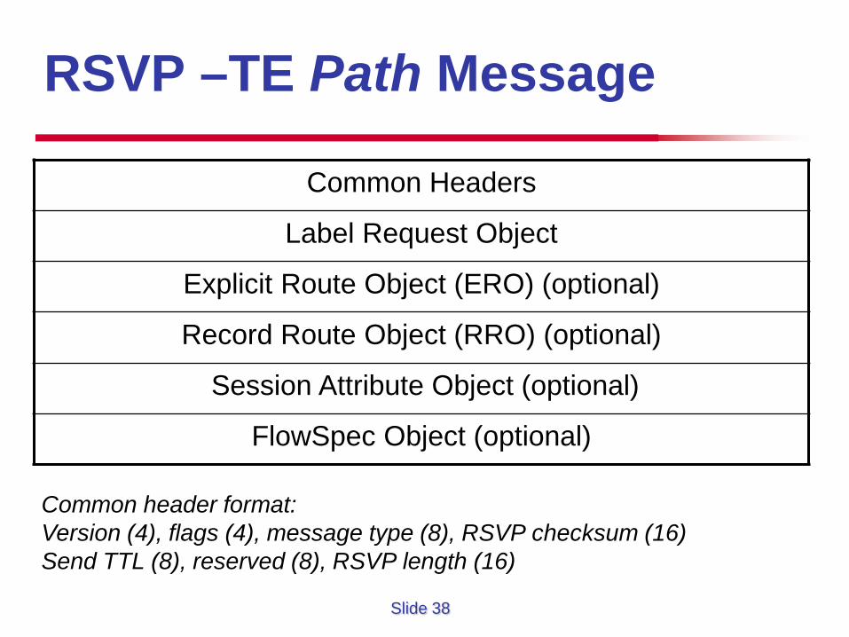
RSVP –TE Path Message
Common Headers
Label Request Object
Explicit Route Object (ERO) (optional)
Record Route Object (RRO) (optional)
Session Attribute Object (optional)
FlowSpec Object (optional)
Common header format: Version (4), flags (4), message type (8), RSVP checksum (16) Send TTL (8), reserved (8), RSVP length (16)
Slide 39
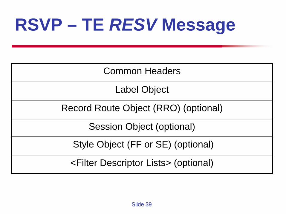
RSVP – TE RESV Message
Common Headers
Label Object
Record Route Object (RRO) (optional)
Session Object (optional)
Style Object (FF or SE) (optional)
<Filter Descriptor Lists> (optional)
Slide 40
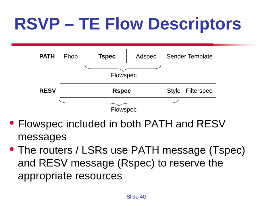
RSVP – TE Flow Descriptors
• Flowspec included in both PATH and RESV messages
• The routers / LSRs use PATH message (Tspec) and RESV message (Rspec) to reserve the appropriate resources
PATH Phop Tspec Adspec Sender Template
Flowspec
RESV Rspec Style Filterspec
Flowspec
Slide 41
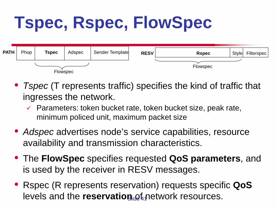
Tspec, Rspec, FlowSpec
• Tspec (T represents traffic) specifies the kind of traffic that ingresses the network. Parameters: token bucket rate, token bucket size, peak rate,
minimum policed unit, maximum packet size
• Adspec advertises node’s service capabilities, resource availability and transmission characteristics.
• The FlowSpec specifies requested QoS parameters, and is used by the receiver in RESV messages.
• Rspec (R represents reservation) requests specific QoS levels and the reservation of network resources.
PATH Phop Tspec Adspec Sender Template
Flowspec
RESV Rspec Style Filterspec
Flowspec
Slide 42
RSVP – TE Styles
• Part of RESV that defines the merging capabilities of the flow
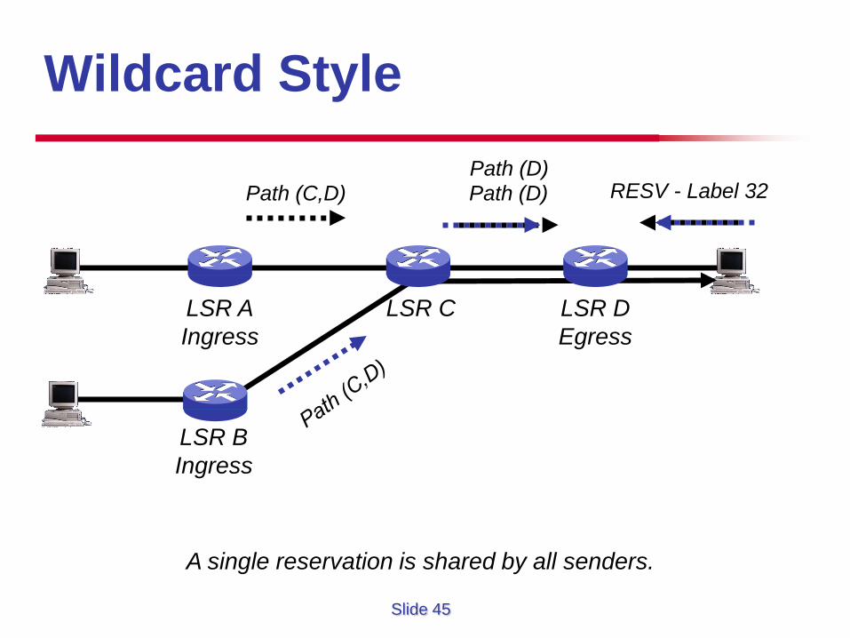
• Wildcard-Filter (WF) style creates a single reservation for all flows from upstream senders
• Fixed-Filter (FF) style – creates a distinct reservation for selected senders
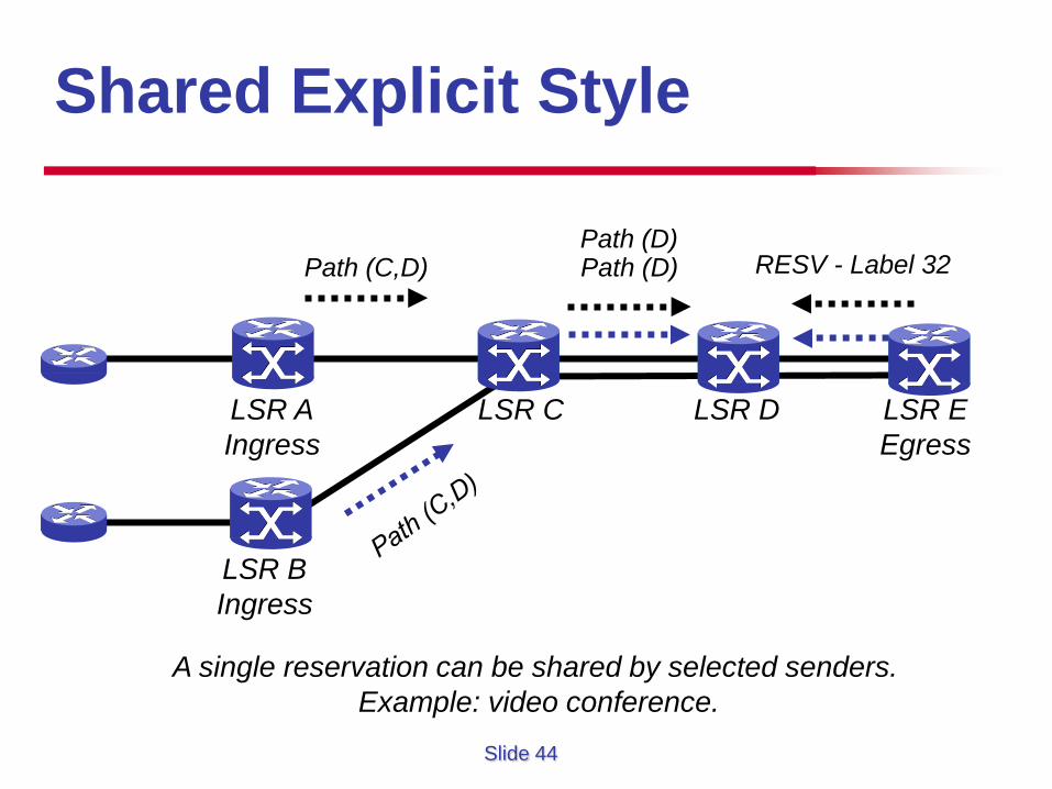
• Shared Explicit (SE) style – creates a shared reservation for selected senders
Slide 43
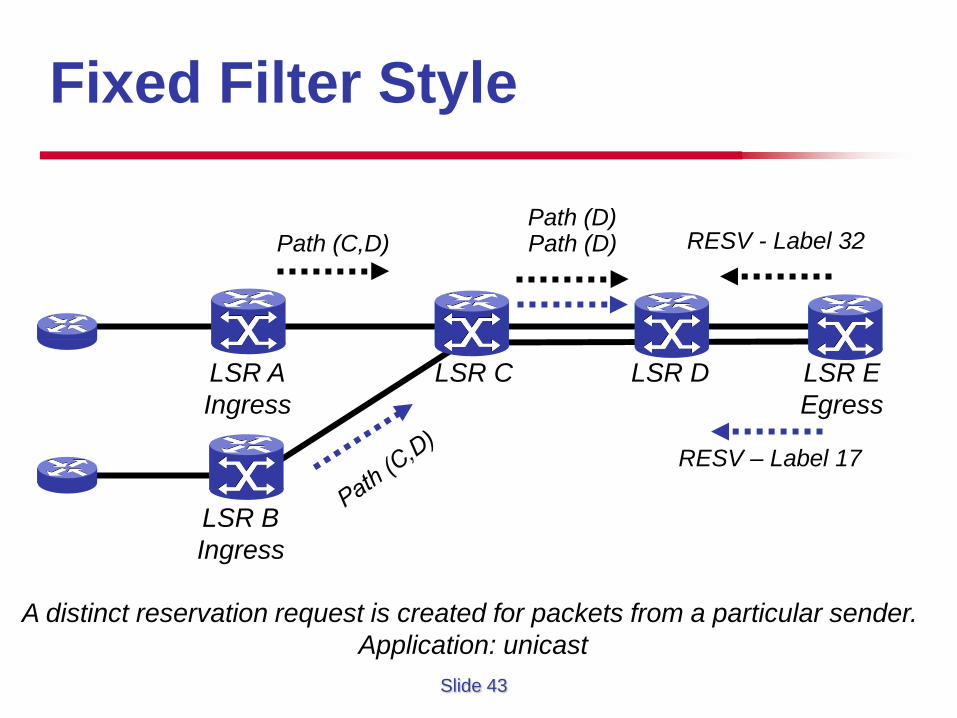
Fixed Filter Style
Path (C,D)
LSR D LSR C LSR A Ingress
RESV - Label 32
RESV – Label 17
LSR B Ingress
Path (D) Path (D)
LSR E Egress
A distinct reservation request is created for packets from a particular sender. Application: unicast
Slide 44
Shared Explicit Style
Path (C,D)
LSR D LSR C LSR A Ingress
RESV - Label 32
LSR B Ingress
Path (D) Path (D)
LSR E Egress
A single reservation can be shared by selected senders. Example: video conference.
Slide 45
Wildcard Style
Path (C,D)
LSR D Egress
LSR C LSR A Ingress
Path (D) RESV - Label 32
LSR B Ingress
Path (D)
A single reservation is shared by all senders.
Slide 46
RSVP – TE PATH Message
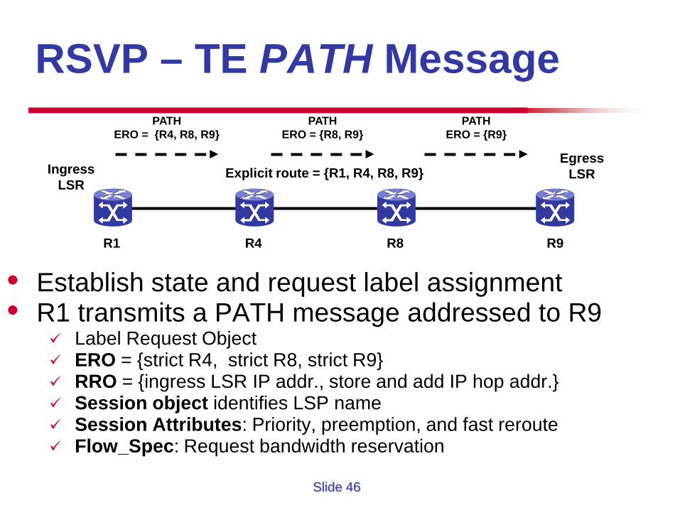
• Establish state and request label assignment • R1 transmits a PATH message addressed to R9
Label Request Object ERO = {strict R4, strict R8, strict R9} RRO = {ingress LSR IP addr., store and add IP hop addr.} Session object identifies LSP name Session Attributes: Priority, preemption, and fast reroute Flow_Spec: Request bandwidth reservation
R1 R4 R8 R9
Ingress LSR
Egress LSR Explicit route = {R1, R4, R8, R9}
PATH ERO = {R4, R8, R9}
PATH ERO = {R8, R9}
PATH ERO = {R9}
Slide 47
RSVP – TE RESV Message
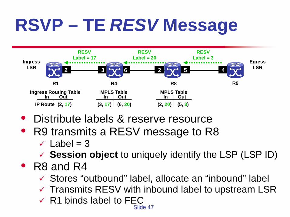
• Distribute labels & reserve resource • R9 transmits a RESV message to R8
Label = 3 Session object to uniquely identify the LSP (LSP ID)
• R8 and R4 Stores “outbound” label, allocate an “inbound” label Transmits RESV with inbound label to upstream LSR R1 binds label to FEC
R1 R4 R8
Ingress LSR
Egress LSR 3 6 2 5 4 2
R9
RESV Label = 3
RESV Label = 20
RESV Label = 17
MPLS Table In Out
(5, 3) (2, 20) In Out
MPLS Table
(6, 20) (3, 17)
Ingress Routing Table In Out
(2, 17) IP Route
Slide 48
CR-LDP vs RSVP-TE
• Signaling Attributes
• LSP Attributes
• Traffic Engineering Attributes
• Reliability & Security Mechanisms
Slide 49
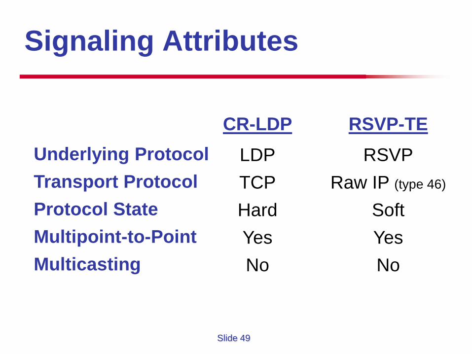
Signaling Attributes
CR-LDP LDP TCP Hard Yes No
RSVP-TE RSVP
Raw IP (type 46)
Soft Yes No
Underlying Protocol Transport Protocol Protocol State Multipoint-to-Point Multicasting
Slide 50
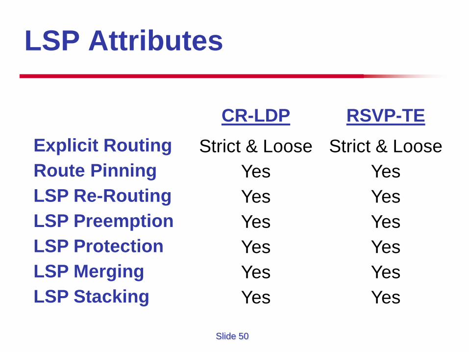
LSP Attributes
CR-LDP Strict & Loose
Yes Yes Yes Yes Yes Yes
RSVP-TE Strict & Loose
Yes Yes Yes Yes Yes Yes
Explicit Routing Route Pinning LSP Re-Routing LSP Preemption LSP Protection LSP Merging LSP Stacking
Slide 51
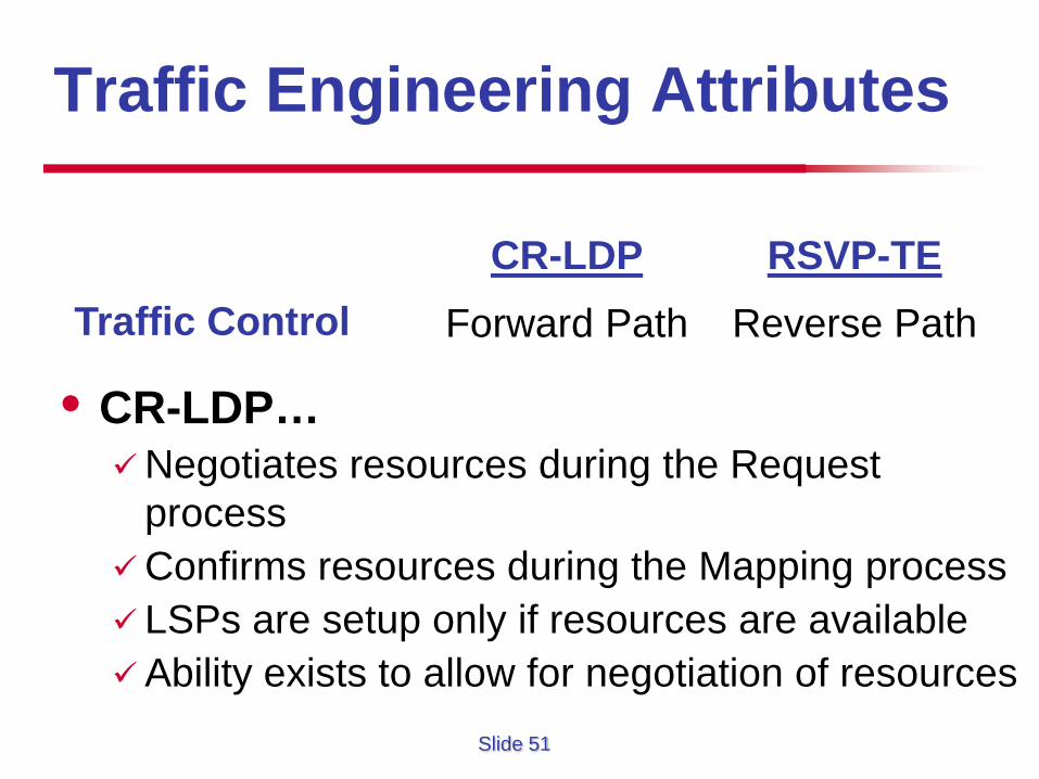
Traffic Engineering Attributes
• CR-LDP… Negotiates resources during the Request
process Confirms resources during the Mapping process LSPs are setup only if resources are available Ability exists to allow for negotiation of resources
CR-LDP Forward Path
RSVP-TE Reverse Path
Traffic Control
Slide 52
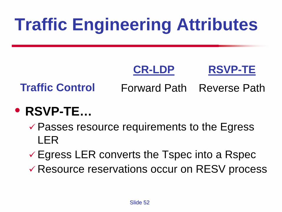
Traffic Engineering Attributes
• RSVP-TE… Passes resource requirements to the Egress
LER Egress LER converts the Tspec into a Rspec Resource reservations occur on RESV process
CR-LDP Forward Path
RSVP-TE Reverse Path
Traffic Control
Slide 53
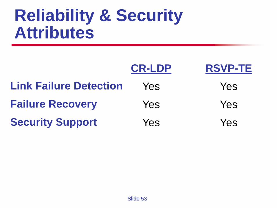
Reliability & Security Attributes
CR-LDP Yes
Yes
Yes
RSVP-TE Yes
Yes
Yes
Link Failure Detection Failure Recovery Security Support
Slide 54
Signaling Protocols
• Each protocol has strengths & weaknesses
• CR-LDP is based upon LDP giving it an advantage of using a common protocol
• RSVP-TE is more deployed than CR-LDP giving it an early lead in the marketplace
• No need for two if there are similar
Slide 55
More on RSVP Operations
• How do some of the protocol mechanisms fit together?
• Make before break: an RSVP-TE mechanism that allows to change some characteristics of a TE tunnel, (bandwidth and the path). No data loss Without double-booking bandwidth May need to reorder packets at egress
• Example
• How to do it? Use Shared Explicit Reservation Style
Slide 56
Make-Before-Break and SER • How does shared explicit reservation work?
Requesting SE reservation Requested by the tunnel headend, ingress
Need to identify that the new request is the same as an existing reservation, so the bandwidth can be shared. All RSVP reservations are uniquely identified with a five-tuple of {sender
address, LSP ID, endpoint address, tunnel ID, extended tunnel ID}. If two reservations share identical data (with the exception of LSP ID), they
are considered two representatives of the same reservation. Only need to reserve the difference
• RSVP is a soft-state protocol, i.e., reservations are periodically refreshed. The format for refreshes are identical to that for new setups.
• How to tell the difference between new setup and refresh? The router will check if it has an existing reservation with the same five-
tuple.
•
Slide 57
Interarea Tunnels
• Up until now, TE tunnels must start/end in the same area (for OSPF) or level (for IS-IS).
• Older versions of router software, a router was limited to a single TE database.
• Newer versions, however, support interarea tunnels.
Slide 58
IGP Terminology • Autonomous System (AS):
Unit of router policy, either a single network or a group of networks controlled by a common network administrator (or group of administrators) on behalf of a single administrative entity (such as a university, a business enterprise, or a business division).
Sometimes referred to as a routing domain. Assigned a globally unique number, sometimes called an Autonomous
System Number (ASN). Networks within an autonomous system communicate routing information to
each other using an Interior Gateway Protocol (IGP); An autonomous system shares routing information with other autonomous
systems using the Border Gateway Protocol (BGP) or Inter-Domain Routing Protocol (IDRP).
• Area: In OSPF, a set of routers that share a common SPF tree or a group of contiguous networks and attached hosts. Why dividing into areas? Area 0 represents a backbone area providing for all inter-area routing. An ABR (Area Border Router) is the one that sits between SPF trees. Example:
Slide 59
What Interarea Tunnels Can Do?
• The interarea tunnels feature allows: TE tunnels between areas (interarea tunnels) TE tunnels that start and end in the same area, on multiple areas
on a router (intra-area tunnels)
• Example: • Most TE tunnels work on an interarea TE tunnel.
Local function of the headend works Static routing and policy routing on tunnels Auto bandwidth
Midpoint features don’t care if a TE is single-area or multiarea. Bandwidth reservation Fast reroute DiffServ-aware traffic eng.
Slide 60
How Interarea Tunnels Work?
• For multiple intra-area tunnels: simple configuration check
• For interarea: Specify an explicit path for the tunnel to take. This explicit path must
use the loose ERO subobject for hops outside its own area. Why?
Strict hops are checked against the TE database to make sure that they are valid.
A router does not know hot to get to anything outside its area. When an ABR receives an ERO with a loose subobject as the next
object in the ERO, it is the ABR’s job to resolve that loose object into a strict one. How? � By running CSPF.
• Example