Embed Size (px)
Citation preview

Page 1 of 25
PATENT AGENT EXAMINATION
PAPER A
2019
Paper A is a patent drafting exercise in which you are being requested to prepare a
full patent specification, with significant weight (60%) given to the claims.
A description of the technology as the hypothetical inventor understands it is
provided in the form of an Invention Disclosure form that has been completed by the
inventor. The inventor has also provided the attached drawings. You are to assume
that there is no more relevant prior art than what is mentioned in the Invention
Disclosure form. You are cautioned not to impart your own knowledge of the subject
matter into your analysis and preparation of the patent application.
On the basis of the description of the invention, drawings, and prior art provided by
the inventor, prepare a patent application. Please note:
The Petition and other such formal portions of an application are not required;
Titles for sections of the patent application must be provided to assist with
correction;
Order of sections of the patent application is not important for Exam purposes.

Page 2 of 25
Claims
You are required to submit a first independent claim of the apparatus type (36 marks)
with six dependent apparatus claims (6 marks, 1 mark each), a second independent
claim of the method type (15 marks) and three dependent method claims (3 marks, 1
mark each). You are to ignore any issues relating to unity of invention.
NOTE: FOR THE DEPENDENT CLAIMS, MARKS WILL BE GIVEN FOR ONLY THE
FIRST 6 DEPENDENT APPARATUS CLAIMS, AND FOR ONLY THE FIRST 3
DEPENDENT METHOD CLAIMS. ADDITIONAL CLAIMS WILL NOT BE MARKED.
DEPENDENT CLAIMS THAT FURTHER DISTINGUISH THE CLAIMED INVENTION
FROM THE PRIOR ART WILL BE GIVEN MORE MARKS THAN DEPENDENT
CLAIMS THAT DESCRIBE KNOWN SUBJECT MATTER
Description of the Embodiments
While clever, the inventor is unlikely to have provided language, structure and
organization appropriate for a patent application. Accordingly, full marks for the
description will not be awarded for merely copying the transcript and, historically,
lower marks have been awarded for exclusively cutting and pasting portions from the
examination itself. The description should not simply consist of an enumeration of
the elements on each figure. The description must address with more details the
point(s) of invention including the subject matter recited in the dependent claims.
Alternative embodiments provided by the inventor should also be discussed.
Drawings
You have been provided with duplicate unmarked copies of the drawings for your
use.

Page 3 of 25
MARK BREAKDOWN
Part A – Long Answer Question
Apparatus claims Method claims
Claim 1 ‐ independent 36 Claim 8 ‐ independent 15
Claim 2 ‐ dependent 1 Claim 9 ‐ dependent 1
Claim 3 ‐ dependent 1 Claim 10 ‐ dependent 1
Claim 4 ‐ dependent 1 Claim 11 ‐ dependent 1
Claim 5 ‐ dependent 1
Claim 6 ‐ dependent 1
Claim 7 ‐ dependent 1
Subtotal 60
Disclosure
Abstract 1 Summary of the Invention 4
Title 1 Brief Description of the
Drawings 2
Field of the Invention 2 Description of the
Embodiments (marks are
allotted for proper reference to
the drawings)
20
Background of the Invention 8
Subtotal 38
Part B – Short Answer Question 2
TOTAL 100

Page 4 of 25
PART A – Long Answer Question (98 points)
Provided below is an Invention Disclosure form that has been completed by an
inventor to explain an invention that she would like her company to patent. The
company that the inventor works for is a packaging company that makes bags that
are used to package food (such as frozen fruits and vegetables) that can be found at
grocery stores.
The inventor has submitted this Invention Disclosure form to her company’s in-house
patent agent for consideration. You have been contacted by this in-house patent
agent and given the mandate to prepare and file a patent application, in Canada, for
the invention described in the Invention Disclosure form. The instructions specify
that the patent application should include:
- an independent apparatus claim; and
- an independent method of manufacture claim.

Page 5 of 25
INVENTION DISCLOSURE FORM
1. TITLE OF THE INVENTION
RE-SEALABLE BAG
2. BACKGROUND TO THE INVENTION
I wanted to make a re-sealable product bag that is better than existing ones (two
examples of existing re-sealable bags are listed in section 5). Re-sealable bags are
typically flexible, or non-rigid, so that they can be rolled, folded or bent once they
have been opened to allow them to be re-sealed.
Existing re-sealable product bags have a number of drawbacks which detract
from their effectiveness. For example, some re-sealable bags use twist ties or
plastic clips that are removable and can be easily misplaced or lost between uses.
They also wear out and stop working very well after repeated use.
Some other re-sealable bags (such as the ones listed in section 5) use adhesives to
close the bag upon itself after opening, but the effectiveness of these adhesives is
known to reduce over time. For example, after repeated exposure to a user’s
fingers, airborne dust, particles, and contaminants, the adhesives don’t work as
well. In addition, the adhesive is generally part of a strip that can be removed
from the bag and lost, or accidentally ripped off at the junction with the bag.
I also find that a lot of re-sealable bags have very complex manufacturing and
assembly techniques.

Page 6 of 25
3. DETAILED DESCRIPTION OF THE INVENTION
My re-sealable bags are intended to be made of materials such as foil, paper,
multi-walled laminate or plastic material and can be used to package food, such as
frozen fruits and vegetables, and snack foods such as chips, cookies and crackers.
My re-sealable bags are able to be reclosed multiple times after the bag’s initial
opening (Figures A and B show the bag open and then closed after opening). The
re-sealing is possible thanks to a layer of non-permanent pressure sensitive
adhesive (PSA) that allows the bag to be rolled down and adhered to the non-
permanent adhesive so that the bag is closed upon itself. The non-permanent
adhesive is applied to the bag in a way that allows it to remain secured to the bag
during its use, so that it can’t be accidentally ripped off, as is possible with some
other re-sealable bags.
An inventive aspect of my invention is that the layer of non-permanent PSA is put
on a side of a carrier strip that has its other side permanently attached to an
external surface of the bag.
Another inventive aspect of my invention is that the non-permanent PSA can be
uncovered gradually so that as the bag is emptied, or as the exposed PSA becomes
less sticky, a fresh portion of the PSA can be uncovered. The non-permanent PSA
is covered by a release liner that can include many segments. When the bag
needs to be closed, one or more segments (usually those closest to the bag’s
opening) is/are removed from the PSA and the bag is folded or rolled down at its
opening until it adheres to the exposed PSA. This structure is shown in my figures
C and D, in which a first segment of the release liner has been removed.

Page 7 of 25
The carrier strip is permanently attached to the bag using a permanent adhesive
(such as a rubber-based adhesive) which has a higher bond strength than the
non-permanent PSA. The term “permanent” means an attachment bond that
would cause damage to either the bag or the carrier strip if removed.
The carrier strip can be made of paper, plastic, vinyl or any other suitable
material and should be flexible and tear resistant.
As illustrated in my figures, the carrier strip has an elongated shape with a length
greater than the width. While a rectangular shape is shown (and preferred),
other shapes such as ovals, etc. and a wide variety of strip sizes could also be
used. The carrier strip is oriented in a direction perpendicular to the opening
edge of the bag, and has a length extending over at least half of the height of the
bag.
As mentioned above, a release liner covers the non-permanent PSA. The release
liner can be made of paper, PET, polyethylene, polypropylene, or any laminate
combination of these materials.
The release liner can be one complete strip of material that can be removed in one
step, or that can be torn at a desired location to expose only a portion of the non-
adhesive PSA. My preferred configuration for the release liner is to have it
divided into multiple segments so that individual segments of the release liner
can be removed from the non-permanent PSA separately. In such a case, the
release liner includes perforation lines dividing the different segments. Each
segment is therefore detachable from the other segments along these
perforations. While perforations are my preferred choice, the release liner could
also be scored to provide scoring lines between individual segments. The
perforations or scoring lines are perpendicular to a longitudinal axis of the carrier
Page 8 of 25
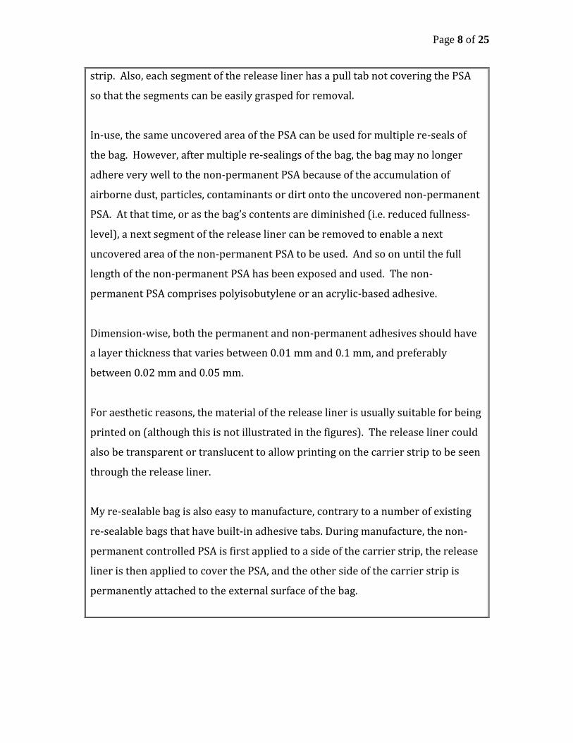
strip. Also, each segment of the release liner has a pull tab not covering the PSA
so that the segments can be easily grasped for removal.
In-use, the same uncovered area of the PSA can be used for multiple re-seals of
the bag. However, after multiple re-sealings of the bag, the bag may no longer
adhere very well to the non-permanent PSA because of the accumulation of
airborne dust, particles, contaminants or dirt onto the uncovered non-permanent
PSA. At that time, or as the bag’s contents are diminished (i.e. reduced fullness-
level), a next segment of the release liner can be removed to enable a next
uncovered area of the non-permanent PSA to be used. And so on until the full
length of the non-permanent PSA has been exposed and used. The non-
permanent PSA comprises polyisobutylene or an acrylic-based adhesive.
Dimension-wise, both the permanent and non-permanent adhesives should have
a layer thickness that varies between 0.01 mm and 0.1 mm, and preferably
between 0.02 mm and 0.05 mm.
For aesthetic reasons, the material of the release liner is usually suitable for being
printed on (although this is not illustrated in the figures). The release liner could
also be transparent or translucent to allow printing on the carrier strip to be seen
through the release liner.
My re-sealable bag is also easy to manufacture, contrary to a number of existing
re-sealable bags that have built-in adhesive tabs. During manufacture, the non-
permanent controlled PSA is first applied to a side of the carrier strip, the release
liner is then applied to cover the PSA, and the other side of the carrier strip is
permanently attached to the external surface of the bag.

Page 9 of 25
4. ADVANTAGES & VARIANTS OF THE INVENTION
4.1 List all advantages of the invention.
Because my new re-sealable bag uses a permanent adhesive that remains
secured to the bag during its use, the carrier strip cannot be accidentally ripped
off from the bag. This prevents a user from losing or destroying the mechanism
that allows the bag to be re-sealed.
In addition, adhering the bag to the non-permanent adhesive prevents the rolled
portion of the bag from unrolling and reduces the amount of air and moisture
that enters the bag. My new re-sealable bag can also be closed at different
fullness levels, which reduces the void space inside of the bag. This in turn
allows the user to maintain the freshness of the bag’s contents, which is
particularly advantageous when the bag is used to contain food products.
The release liner segments also provide additional areas of adhesive when an
exposed area of the PSA has lost its adhesive strength.
4.2 Describe any variants/alternatives for this invention that would achieve the same result
Techniques other than permanent adhesive can be used to permanently attach
the carrier strip to the bag. For example, heat lamination or ultrasonic welding
can be used to permanently attach the carrier strip to the bag.
There are also different ways of manufacturing my re-sealable bag. For instance,
the carrier strip can be provided from a continuous tape of carrier material that
has been coated on one side with the non-permanent PSA. The release liner can

Page 10 of 25
similarly be fed from a continuous tape that is applied to the continuous tape of
carrier material, over the PSA.
The perforations can be formed in the tape of release liner prior to its application
to the carrier material tape. The release liner pull tabs can be formed by aligning
the release liner tape over the carrier material tape so that the release liner tape
overhangs the carrier material tape. The combined tapes are then cut into
individual sections (sized to fit the bag) and placed on the bag as part of its in-line
manufacturing process.
Alternatively, the carrier material tape can be die-cut off line into individual
carrier strips and applied to the release liner tape. The release liner tape can then
be die cut off line into individual sections and applied to the bag. Alternatively, the
release liner tape can be cut into individual sections and applied to the individual
carrier strips.
Figures E and F also show a different configuration for the non-permanent PSA on
the re-sealable bag. In this alternative configuration, the layer of non-permanent
PSA layer is divided into multiple portions that are spaced apart from each other.
As such, there are gaps in the non-permanent PSA, which create adhesive free
zones. These adhesive free zones correspond with the multiple segments of the
release liner, meaning that the perforations of the release liner are aligned with
the adhesive free zones between the PSA portions.
5. RELEVANT PRIOR ART DOCUMENTS
Type of Doc. Title Date of Document
5,XXX,XXX (Storkin) D1
Reclosable packaging 4/5/1991
6,YYY,YYY (Stevens) D2
Bag with built-in closure 5/4/1994

Page 11 of 25
Figure A
Figure B
rolled down opening
bag
pull tab
release liner
non-permanent
adhesive
re-sealable
bag
bag opening

Page 12 of 25
Figure C
Figure D
carrier strip
permanent adhesive
non-permanent adhesive (PSA)
liner segments
perforation lines
liner segments
release liner
pull tabs
perforation lines
non-permanent PSA
carrier strip
permanent adhesive bag
liner
segments release liner

Page 13 of 25
Figure E (Alternative embodiment)
Figure F (Alternative embodiment)
permanent adhesive
perforation line adhesive free
zone
liner
segment adhesive free
zone release liner
PSA portion
carrier strip
bag
release liner
pull tab
PSA portions
re-sealable
bag
perforation line
bag opening

Page 14 of 25

Page 15 of 25
D
D

Page 16 of 25

Page 17 of 25
United States Patent [19] Storkin
[11] Patent Number: 5,XXX,XXX [45] Date of Patent: April 5, 1991
______________________________________________________________________________
[54] RECLOSABLE PACKAGING
[75] Inventor: Anthony STORKIN
Malibu, CA
[73] Assignee: Storkin Industries,
Palo Alto, CA
[21] Appl. No.: 08/ABC,DEF
[22] Filed: Mar. 18, 1989
Primary Examiner - Downs, R.
[57] ABSTRACT
A reclosable package comprises an adhesive
layer that extends the full width of a flexible strip
of material. Formation of a dry edge on the strip,
suitable for grasping by a user, is accomplished
either by adhering a piece of material such as a
dry tape over a portion of the adhesive layer or by
the application of a liquid overcoating which
chemically deadens the adhesive.
1 Drawing Sheet
U.S. Patent No. 5,XXX,XXX

Page 18 of 25
FIG. 1
FIG. 2
FIG. 3

Page 19 of 25
RECLOSABLE PACKAGING
FIELD OF THE INVENTION
This invention relates to reclosable
packages, and more particularly to flexible bags
or pouch-type packages typically used for
packaging food products where the package
contents are not fully consumed within one
opening of the package and it is desirable to
reclose the package to store the remainder of the
contents for subsequent use.
BACKGROUND OF THE INVENTION
Few satisfactory closure systems are
available to re-close heavier weight foil
packaging, paper bags, or multiwalled laminate
packages used to package such items as potato
chips and other snack items, lawn care products,
dog food and the like. A common method of
closing such flexible product bags involves
expelling the air from the bag, pressing two sides
of the bag together, and rolling the bag down from
the top. The consumer normally relies on a
number of folds or creases made in that rolled
portion of the bag to hold the shape of this rolled
portion and to keep out undesired moisture and
air. However, over time or as a bag is transported,
the rolled portion loosens and may permit the
contents to spill out or allow air and moisture to
enter the bag through the opening, thereby
causing the product to spoil, become stale, or take
on other undesirable properties.
SUMMARY OF THE INVENTION
The novel reclosable packaging
according to the present invention utilizes a
reclosure strip. In accordance with the present
invention, an adhesive layer extends the full
width of a flexible film strip. Formation of a dry
edge of the strip suitable for grasping by the user
is accomplished in either of two ways. In one
embodiment, a strip of material, i.e., a dry tape, is
applied onto the adhesive extending
longitudinally along one edge of the film strip.
The adhesive secures the tape to the film strip and
provides a dry edge by forming an overlaying
barrier between the user and the adhesive. In an
alternate embodiment, the longitudinally
extending barrier to the adhesive along one edge
of the flexible film strip can be provided by the
application of a liquid overcoating which
chemically deadens the adhesive. The
overcoating makes the film strip dry to the touch
and easy to grasp by the fingers of the user. The
reclosure strip is laterally positionable anywhere
along the running length of the package.
DESCRIPTION OF THE DRAWINGS
FIG. 1 is a perspective view of a flexible
package with a package reclosing strip shown
thereon, in accordance with an embodiment of the
present disclosure;
FIG. 2 is a perspective view of the
package of FIG. 1 which has been opened and had
product removed, and with the open package top
partly rolled down, but with the partly detached
reclosing strip not yet applied to the rolled down
package top to hold it closed; and
FIG. 3 is a perspective view of the
package of FIG. 2 with the reclosing strip applied
to the rolled down package top to hold it closed.
DESCRIPTION OF THE PREFERRED
EMBODIMENT
FIG. 1 shows a reclosable package 23,
having top and bottom seals 24 and 25, a
longitudinal seal 21, and with a package reclosing
strip 14 adhered to the package and extending
from the package top seal 24 to its bottom seal 25.
As seen in FIGS. 1 through 3, the package
reclosing strip 14 is a composite strip formed
from a single-faced, adhesive-coated flexible film
strip 28 and a dry tape 30. An adhesive coating 29
extends the full width of the film strip 28. The dry
tape 30 is longitudinally coextensive with and
adhered to a lateral portion of the film strip 28 by
the adhesive coating 29.
The film strip 28 could be made of one of
paper, plastic, or vinyl, coated with a pressure-
sensitive adhesive 29 such as a rubber-based
solvent adhesive, in the thickness range of 0.01 to
0.1 mm in coat weight. In some aspects, the
adhesive coating 29 is in the thickness range of
0.02 to 0.05 mm in coat weight.
The adhesive coating 29 provides a
protective barrier and a means to adhere tape 30.
The adhesive portion of the film strip 28 not
covered by the tape 30 secures the reclosing strip
14 to the package 23, while the tape 30 provides
a dry edge suitable for grasping by a user.
Referring now to FIGS. 2 and 3, the
reclosing strip 14 is activated by grasping the film

Page 20 of 25
strip 28 by the dry tape 30 and lifting or pivoting
it outward. As shown in FIG. 2, the package 23
has been opened and some contents removed. The
construction of the invention facilitates grasping
the reclosing strip 14 by the dry tape 30 and
pulling the strip 14 downward to partially detach
it from the package 23, which is then rolled down
as shown. The detached section of the reclosing
strip 14 is then laid over and detachably sealed to
the rolled down package top by way of the
exposed adhesive coating 29 on the film strip 28,
as shown in FIG. 3. The film strip 28 is adhered
to the package 23 and secured thereon by
adhesive layer 29. The next time that it is desired
to remove some of the contents from the package
23, the reclosing strip 14 is peeled down so that
the package top may be unrolled for dispensing
product, and the same reclosing process is then
again performed. The reclosing strip 14 is
progressively re-attachable to different points on
the package 23 to hold the package 23 closed at
selected reduced sizes as product is removed from
the package 23.
In this embodiment of the invention, the
film strip 28 could typically be about 12.7 mm
wide and the dry tape 30 could be about 19 mm
wide, with about 6.35 mm widthwise overlap of
the tape 30 onto the film strip 28 to provide a
composite reclosing strip 14 of about 25.4 mm in
width.
In an alternate form of the invention, tape
30 may be replaced by a liquid coating which
chemically deadens the tackiness of the adhesive
coating 29, rendering it dry to the touch. In either
case, any printed graphics on the film strip 28 in
the area of the dry edge are protected against
frictional wear by the adhesive coating 29, which
is subsequently partially covered either by the dry
tape 30 or the liquid coating.

Page 21 of 25
United States Patent [19] Stevens
[11] Patent Number: 6,YYY,YYY [45] Date of Patent: May 4, 1994
______________________________________________________________________________
[54] BAG WITH BUILT-IN CLOSURE
TAB
[75] Inventor: Roger STEVENS
Brooklyn, NY
[73] Assignee: Adhesives Co.,
Seattle, WA
[21] Appl. No.: 08/JKL,MNO
[22] Filed: June 26, 1992
Primary Examiner - Evanston, C.
[57] ABSTRACT
A bag having a built-in closure tab is defined. The
closure tab is formed from the outer layer of
laminate which makes up the bag. When a user
wishes to close the bag, the user folds or rolls the
sides of the bag together down the side of the bag
having the tab. The tab is partially separated from
the rest of the outer layer of the laminate. A
pressure sensitive adhesive disposed on the
interior surface of the tab is used to affix the tab
to the rolled down portion of the bag, preventing
unwanted opening of the bag. The tab may be
affixed and removed from the rolled down
portion a number of times, thereby allowing the
user to repeatedly open and reseal the bag.
1 Drawing Sheet

Page 22 of 25
U.S. Patent No. 6,YYY,YYY
FIG. 2
FIG. 1
FIG. 3 FIG. 4

Page 23 of 25
BAG WITH BUILT-IN CLOSURE TAB
FIELD OF THE INVENTION
The invention relates to a resealable bag.
More particularly, the invention is directed to a
bag having a built-in reusable closure tab.
BACKGROUND OF THE INVENTION
Film bags are used for containing a wide
variety of items, such as food items. A typical
film bag is made from a laminate that includes an
outer film layer adhesively secured to an inner
layer that allows the package to be sealed. The
outer and inner layers are both typically made
from plastic film, such as polyethylene or
polypropylene.
The conventional bag is closed by
bringing two opposing sides into contact and
downwardly folding or rolling them together.
When closed, the bag may tend to free itself from
the rolled configuration, thereby reopening and
exposing its contents to ambient air. Various
methods of preventing the conventional bag from
reopening have been attempted, such as using
clips, twist ties, and adhesive tape. However,
these things have a tendency to be misplaced and
are often unavailable when needed.
SUMMARY OF THE INVENTION
The invention is directed to a bag having
an inner layer and an outer layer, which form the
sides of the bag, with a portion of the outer layer
defined as a reusable built-in closure tab. The tab
portion is mostly separable from the remainder of
the outer layer, the remainder of the outer layer
defining a fixed portion of the outer layer. The tab
portion is attached to the fixed portion of the outer
layer only at its base. A pressure sensitive
adhesive, rather than a permanent adhesive, is
disposed on the underside of the tab, releasably
attaching the tab to the inner layer. Thus, the tab may be easily pulled away from the inner layer,
although remaining attached to the inner layer
and the fixed portion of the outer layer at its base.
The pressure sensitive adhesive disposed on the
inside of the tab may be used to affix the tab to a
rolled down portion of the bag, thereby sealing
the bag closed.
DESCRIPTION OF THE DRAWINGS
Referring to the drawings, wherein like
elements are numbered alike in the several
FIGURES:
FIG. 1 is a front elevational view of an
open bag according to the present invention;
FIG. 2 is a cross sectional view of a
portion of the side of the bag shown in FIG. 1,
taken along lines 2--2 in FIG. 1;
FIG. 3 is a perspective view of the bag
shown in FIG. 1 in a closed configuration; and
FIG. 4 is a schematic view of the bag
shown in FIG. 1, showing the built-in closure tab
being transparent to show its underside.
DESCRIPTION OF THE PREFERRED
EMBODIMENT
With reference to FIG. 1, there is shown
a film bag 10. Disposed on a wall of the bag 10 is
a built-in reusable closure tab 20.
Bag 10 has a front wall 12 and a back
wall 14. The walls 12, 14 of the bag 10 are formed
from a laminate having at least two layers. Tab 20
is provided on front wall 12 and is formed from
an outer layer 34 of the laminate, as seen in FIG.
2.
Generally, tab 20 is substantially
coplanar with the remainder of the front wall 12
before the bag 10 is opened. While tab 10 is
shown having a rectangular bottom portion and a
curved top portion, the person skilled in the art
would understand that the tab could be any
elongate shape, such as a rectangle or oval.
Once a user opens the bag 10 and
consumes a portion of the contents stored therein,
the user brings both walls 12, 14 of the bag 10
together to re-close the top of the bag 10. The user
pulls at least part of the tab 20 away from the
plane of the wall 12. The top of the bag 10 is then
rolled or folded down, the roll forming along
front wall 12. The user then engages the tab 20
with the rolled portion, the tab 20 adhering to the
folded portion with enough affinity to prevent the
bag 10 from unrolling.
FIG. 2 shows a schematic cross section of
a portion of the front wall 12, taken along line 2-
-2 of FIG. 1. The laminate that forms bag 10
comprises an inner layer 30 and an outer layer 34.
The inner layer 30 is substantially uniform across
the entire bag, there being no holes, cut-outs or
regions substantially different than the rest.

Page 24 of 25
The outer layer 34 is bonded to the inner
layer 30 by a permanent adhesive 28, except for a
knock-out zone 16 which is not bonded with
permanent adhesive 28. Thus, the outer layer 34
comprises two portions: the fixed portion and the
tab 20. The fixed portion of outer layer 34 is
permanently adhered to inner layer 30. The area
of the outer layer 34 corresponding with knock-
out zone 16 forms tab 20. The knock-out zone 16
extends near enough the bottom of the bag 10 as
to be capable of releasing the closure tab 20 for
effective closure of bag 10, even when bag 10 is
nearly empty.
As seen in FIGS. 3 and 4, tab 20 is never
fully removed from the fixed portion of outer
layer 34. Rather, tab 20 remains tangentially
attached to the remainder of outer layer 34 along
a line or region to avoid accidental total
separation. The tab 20 may be formed by any
process capable of accurately cutting the outer
layer 34 while leaving the inner layer 30 intact.
Within the knock out zone 16, where
permanent adhesive is not dominant, a pressure
sensitive adhesive (PSA) 22 is provided. The
particular PSA selected for use may vary
depending on the material of outer layer 34. The
PSA should, however, have a greater affinity for
the interior surface of outer layer 34 than for the
inner layer 30 and the exterior surface of outer
layer 34. It is preferable to use an adhesive which
is pressure sensitive such that the closure tab 20
may be applied and removed a plurality of times
from engagement with inner layer 30 and with the
fold of bag 10, as shown in FIG. 3.
In one embodiment, PSA 22 is provided
in zones, shown as 22a through 22c in FIG. 2.
When the PSA 22 on the tab 20 is provided in
zones, only one zone need be used at a time,
keeping the remaining zones free of dust or other
potential contaminants. Once the PSA 22 on the
zone in use has reached the end of its useful life,
the user may expose the next zone for use.
Separating each zone is a gutter of a stronger
adhesive 24, shown as elements 24a and 24b in
FIG. 2. For purposes herein, a "stronger adhesive"
means any adhesive with a greater affinity to
inner layer 30 than the affinity of PSA 22 to inner
layer 30. As such, stronger adhesive 24 may be
another PSA or may be a heat curable adhesive.
However, stronger adhesive 24 should not be so
strongly adhered to inner layer 30 as to be
inseparable therefrom without causing damage to
tab 20 or inner layer 30.
It is preferred to provide an adhesive-free
zone 26 at the tip of the tab 20. The adhesive-free
zone 26 may be provided to assist the user in
grasping the tab 20 for separation thereof from
inner layer 30.
When the PSA 22 is provided in zones,
as shown in FIGS. 2 and 4, a user may grasp the
tip of tab 20 and pull with an adequate force to
separate PSA zone 22a from inner layer 30. The
force initially used should not be so great as to
separate stronger adhesive 24a from inner layer
30. Thus, the user may initially reveal only zone
22a, keeping zones 22b and 22c protected from
contamination. With zone 22a revealed, the user
may roll down the bag 10, such as one might
normally do to close a bag, and affix zone 22a to
the rolled portion to ensure the bag 10 remains
closed. FIG. 3 shows the tab 20 affixed to the
rolled portion.
In the event PSA 22a loses its affinity and
fails to properly keep the bag closed or if it is
desired to roll the bag down beyond where tab 20
remains affixed to inner layer 30, the user may
reveal an additional PSA zone 22b. The user may
do so by pulling tab 20 away from inner layer 30
with adequate force to separate a first stronger
adhesive gutter therefrom, identified by the
numeral 24a in the drawings. The separation of
stronger adhesive 24a from inner layer 30 reveals
PSA zone 22b. Tab 20 may then be affixed to the
folded portion of the bag 10 via PSA 22b, in a
way similar to that shown in FIG. 3.
Additional PSA zones 22 may be
sequentially revealed as needed. It is preferable
that the last PSA zone 22 be near the bottom of
the bag such that it is capable of holding the bag
10 closed when the bag 10 is nearly empty and
the user rolls or folds the bag 10 downwardly to
near its bottom.
Three zones of PSA22, as shown in the
drawings, may be adequate for the design of most
bags. However, more zones may be desirable for
very large bags or bags which a user must open
and reseal an excessive number of times.

Page 25 of 25
PART B – Short Answer Question (2 points)
When preparing the patent application, you were specifically instructed by the
packaging company to prepare an independent claim towards a method of
manufacture. Given the nature of the product being patented, please provide at least
one reason why the packaging company might not have asked for an independent
claim towards a method of use?
END OF PAPER A EXAM