Embed Size (px)
Citation preview

Licensee OA Publishing London 2013. Creative Commons Attribution License (CC-BY)
Patel V, Venkatarayappa I, Prayson MJ, Goswami T. Biomechanical evaluation of hybrid locking plate constructs. Hard Tissue 2013 Jun 01;2(4):32.
Com
petin
g in
tere
sts &
Con
flict
of i
nter
ests
: Non
e de
clar
ed.
All a
utho
rs c
ontr
ibut
ed to
con
cept
ion
and
desig
n, m
anus
crip
t pre
para
tion,
read
and
app
rove
d th
e fin
al m
anus
crip
t.
All a
utho
rs a
bide
by
the
Asso
ciat
ion
for M
edic
al E
thic
s (AM
E) e
thic
al ru
les o
f disc
losu
re.
1
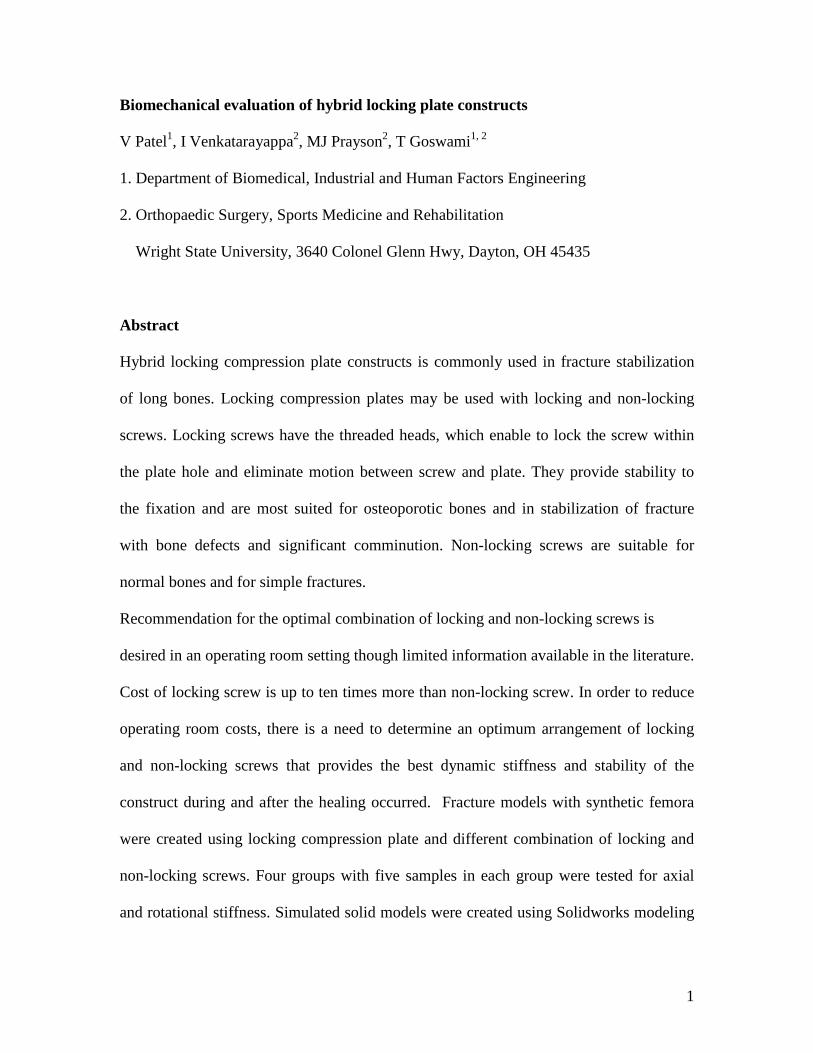
Biomechanical evaluation of hybrid locking plate constructs
V Patel1, I Venkatarayappa2, MJ Prayson2, T Goswami1, 2
1. Department of Biomedical, Industrial and Human Factors Engineering
2. Orthopaedic Surgery, Sports Medicine and Rehabilitation
Wright State University, 3640 Colonel Glenn Hwy, Dayton, OH 45435
Abstract
Hybrid locking compression plate constructs is commonly used in fracture stabilization
of long bones. Locking compression plates may be used with locking and non-locking
screws. Locking screws have the threaded heads, which enable to lock the screw within
the plate hole and eliminate motion between screw and plate. They provide stability to
the fixation and are most suited for osteoporotic bones and in stabilization of fracture
with bone defects and significant comminution. Non-locking screws are suitable for
normal bones and for simple fractures.
Recommendation for the optimal combination of locking and non-locking screws is
desired in an operating room setting though limited information available in the literature.
Cost of locking screw is up to ten times more than non-locking screw. In order to reduce
operating room costs, there is a need to determine an optimum arrangement of locking
and non-locking screws that provides the best dynamic stiffness and stability of the
construct during and after the healing occurred. Fracture models with synthetic femora
were created using locking compression plate and different combination of locking and
non-locking screws. Four groups with five samples in each group were tested for axial
and rotational stiffness. Simulated solid models were created using Solidworks modeling

2
and finite element analysis was performed and the results were compared with
experimental results. The results from this experimental program indicate that locking
screws should be placed near the fracture gap to gain axial and torsional strength. Also,
locking screws impart higher resistance to loosening of the adjacent level non-locking
screws as found in this synthetic femur study.
Keywords locking compression plate, locking screw, non-locking screw, dynamic
stiffness, finite element model, displacement

3
1.0 Introduction
An open reduction and internal fixation (ORIF) procedure is performed over 4 million
times in the United States annually. A hybrid plate construct involves the use of locking
screw and conventional cortical or cancellous screw. Internal fixation devices work as
load sharing or load bearing devices. Plate osteosynthesis in comminuted fracture acts as
load bearing device where the plate assumes all the loads. Compression plating in simple
fracture pattern works as load sharing devices where bone assumes most of the load.
Fracture healing leading to bone union depends on the devices used and their
biomechanical behavior. Hence it is important to obtain stable fixation to prevent implant
failure. Implants are not routinely removed unless there is infection or mechanical
failures. Internal fixation devices are of many types. Some of the commonly used
devices include K-wires, Plates, Screws, intramedullary rods etc., K-wires are mainly
used as reduction tool and sometimes in stabilizing fractures of small bone in hand and
feet.
Different types of plates used for internal fixation include locking compression plate,
dynamic compression plate, and reconstruction plate. Dynamic and locking compression
plates are more commonly used. Locking compression plate acts as internal external
fixator. They have very limited contact with the bone and hence reduce vascular damage.
This has a great advantage in osteoporotic bone and in fractures with significant
comminution and bone loss. Locking compression plates provide relative stability at the
fracture site and facilitate bone healing by secondary intention1-10.
Conventional plate osteosynthesis offers stability by friction between plate-bone
interface. On axial loading, bending force is applied on the screws, which generate a

4
shear force. When axial load exceeds the friction force, movement occurs between the
plate and screws, known as toggle, and may result in bending or fracture of screws. The
change in plate screw angle limits failure loads to the strength of thread purchase.
Screws alone may be used as primary mode of fixation in small bone fractures in hands
and feet. Intramedullary rods are more commonly used in midshaft fractures of femur
and tibia.
Previous studies have evaluated the mechanical properties of hybrid plate construct in fourth-generation composite bone model11. The potential advantage of locked screws in improving the axial and torsional strength and different combination of locked and non- locked screws have been studied12. To our knowledge there is no study, evaluating the dynamic stiffness of Hybrid construct at different stages of healing process.
2.0 Materials and Methods
In this study synthetic femur models (Model 3403, pacific Research Laboratories,
Vashon, USA) which contain epoxy glass fiber as shallow cylinders filled with
polyethylene were used. Fracture comminution was simulated by an osteotomy gap of
2cm in the metaphyseal region using twenty synthetic femur models. Ten hole pre-
contoured lateral distal femoral locking plate implants were used and simulated fractures
were stabilized with different combination of locking and non-locking screws. The femur
fracture constructs were divided into four groups as shown in Table-1. Five femurs were
prepared for each of the 4 groups. The test protocol was kept same for all 4 groups of
testing where load was cycled in the negative Y direction from 50 to 700 N and a torsion
rotation of + 5º /cycle applied in a sinusoidal waveform. At the end of 50,000 cycles tests
were stopped. The details of the specimen preparation and specimen testing are available

5
elsewhere10-11. Simulated solid models were constructed to perform finite element
analysis so that these results could be compared with the experimental results.
2.1 Solidworks Modeling
Solid models of LCP were created similar to Synthes condylar plates through Solidworks
2007, a three-dimensional (3D) Computer Aided Design (CAD) software. The non-
locking screw heads were minimized in size to decrease contact with the plate hole as
shown in Figure 1. The distal condylar flared portion of the plate was designed with loft
and fillet (Loft and Fillet are features used in Solidworks for creating transitions and
external/internal round surfaces, respectively) operations as shown in Figure 2. A final
assembly was created joining the various individual model portions. This assembly was
similar in appearance to the femoral constructs tested experimentally. Additional groups
were created for completeness. Plating constructs with three locking screws and one non-
locking screw were developed as well as plates with four locking screws. The bony
segments (condylar and shaft) were subtracted for further analysis in ANSYS, (ANSYS
Inc, Canonsburg, PA). Appropriate constraints were applied at the plate ends and on the
screws. The model was then saved in a para-solid format. Three-dimensional models of
the femur were also created using Mimics (Materialise, Inc, Plymouth, MI), which is a
3D modeling software that imports computed tomography (CT) imaging data. The CT
images of the specimens were acquired from Miami Valley Hospital in Dayton, OH.
Three-dimensional models, similar to the anatomical specimens, were achieved using the
Mimics tools as seen in Figure 3.

6
2.2 FEA analysis in ANSYS
The Solidworks models stored in parasolid format were imported into ANSYS. Stainless
steel (316L) properties were assigned to the plate and screws built with SHELL 93
elements. Loads were applied to the screws with the plate and screws constrained. A
time harmonic mode was chosen which converts loads in terms of displacement and
stress. Loads of 300N were applied to each screw in a negative Y direction (downward).
From the obtained results, construct dynamic stiffness and deformation were measured.
3.0 RESULTS
3.1 Finite Element Analysis
Table-2 summarizes the results of finite element analysis in terms of maximum stress and
maximum displacement that occurred in different screws. Maximum stress occurred in
plates with all non-locking screws. Stresses were the lowest in plates with all locking
screws. A maximum stress of 449 N/m2 occurred in plates with all non-locking screws,
427 N/m2 in plates with three non-locking screws, 373 N/m2 and 341 N/m2 in plates with
two and one non-locking screws, respectively. A lowest maximum stress of 190 N/m2
occurred in plates with all 4 locking screws. Total displacement of locked construct was,
however, higher than all other combinations. It may be noted that the displacement
considered here were in nano-meters, and operating room practice allows 10% of the
fracture gap as a rule of thumb. Figure 4 shows the ANSYS models with all 4 locked and
non-locked constructs.
3.2 Experimental Program
Experimental data generated on 20 synthetic femurs has been tabulated in Table-3.
Groups 2 and 3 exhibited higher torque to loosen the screws. However, locking screws

7
when positioned either immediately after the osteotomy gap, or at the distal end of the
plate, exhibited similar amount of torque required to loosen the screw. More than one-
half of torque was retained in the screw at the end of 50,000 cycles. Constructs made with
conventional screw, on the other hand, loosened most of their insertion torque and were
loose enough that torque meter did not read the remaining torque. Remaining torque was
measured by subtracting the loosening torque from insertion torque.
The conventional screw, located in Screw-2 position, maintained somewhat lower torque
than Screw-3. The average torque of locking screws, farthest and closest from the
osteotomy gap, remained very similar10-11. Similarly, non-locking screws farthest from
the gap showed low loosening torque compared to the non-locking screws nearer to the
fracture gap. Table-4 summarizes average remaining torque, percentage loosening torque,
axial stiffness, average torsional stiffness, and average deformation of each of the screws.
It may be noted that a construct, collectively with locking and non-locking screws, had an
axial stiffness range from 200 to 4000 N/mm, whereas the torsional stiffness range was
50-350 N×mm/º rotation and average deformation range was 0.5-2.5 mm.
The dynamic stiffness was plotted with respect to the number of cycles for all the 4
groups, Figures 6-9. The dynamic stiffness in Group 1 varied with respect to number of
cycles in a sine function, representative of harmonic oscillation and may indicate the
density and/or porosity variation in the construct, and is not of interest in this study.
However, the Group 1 harmonics may indicate severe displacement changes during the
tests. The displacement data was reviewed for all the groups and no trends were found
that can be reported here. In all the tests, the displacement at the end of 50,000 cycles was
the highest. The total deformation varied, as noted earlier from 0.5 to a worst case

8
scenario of 2.5 mm. The displacement data for Group 1 is shown in Figure10 showing
normal, gradual accruing of deformation as the cycles continue. Since the significant drop
in stiffness occurs during the initial stages of cyclic loading, as shown in Figures 6-9, the
first 20,000 cycles are therefore very important in fracture fixation and healing. The
remaining torque begins to deplete at this point and may be the reason why loosening of
screws or screw pull-out is observed as a failure mode. The negative slope of the dynamic
stiffness for Group 4 constructs may be described by
Dynamic stiffness = -1E-20N5 + 2E-15N4 - 1E-10N3 + 3E-06N2 - 0.0403N+ 503.23
Where, N is the number of cycles.
The efficacy of a hybrid construct depends on the dynamic stiffness exhibited by the
construct. From Figures 6-9 it is obvious that lower stiffness ranges found for Groups 1-3
may loosen the constructs in the long run, and must show the remaining stiffness higher
than 100-200N/mm. Therefore, Group 4 provides the most effective fixation stability
with 2 locking screws one on each proximal and distal end from the osteotomy. Fixation
efficacy was found to be with the use of 2 locking screws for the study groups
investigated in this paper with dynamic stiffness range of 200 N/mm at the end of 50,000
cycles. However, the dynamic stiffness was expected to be much higher during the
insertion of the device, 500 N/mm, as shown in Figure 9 using 2 locking screws. None of
the other constructs show higher starting stiffness as Group 4. The starting stiffness
ranges from 100 to 300 N/mm. This study used 2 cm osteotomy gap, where high
stress/strain was likely to develop causing significant amount of axial and angular
displacements. Additional work is recommended for smaller osteotomy gaps to determine
the efficacy of the hybrid locking plate constructs.

9
4. DISCUSSION
The LCP is subjected to static and cyclic loads in vivo which generate extremely
complicated stress systems in the device2. Materials with a very high Young’s Modulus
make the plate stiff. Stiff plates do not transfer as much stress to the bone in the local area
causing the bone to thin or deplete its composition. This phenomenon is known as stress
shielding and causes osteopenia3. It is usually visible on the X-rays showing a region
darker than the superior or inferior regions. Therefore, materials that possess suitable
stiffness must be considered for use as LCP. Materials with a low modulus of elasticity
do not provide enough rigidity to the bone to heal the fracture, and materials with a high
elastic modulus increase rigidity and lower stresses in the bone; thus causing stress
shielding. For the fixation devices, stainless steel- 316L, remains the preferred material of
choice and used in this study.
Efficacy of the LCP performance depends on fracture type. Conventional compression
plate performs well for normal quality of bone and fracture with normal or partial contact
between fragments. When both ends of the bone fragments are not in contact with each
other, a bridge plate technique may be used either with locked or standard screws based
on the bone quality. A combination technique is employed for simple oblique or articular
fracture with more standard screws and fewer locking screws. An osteotomy gap of 2 cm
was used in this study, simulating significant bone loss and fragmented fracture. The
length of LCP is dependent on fracture length and loads being transferred to the plate
(e.g. bending, pull out)4. The ratio of the plate length to the fracture length is called plate
span width5. Guatier and Sommer recommended plate span width to be from 2 to 3 for
comminuted fracture and 8 to 10 for simple fracture6. This suggests that for more

10
comminuted fracture; a long plate provides higher axial and torsional stability than the
short plate7. Working length is the length between two screws of two different fracture
fragments. With a small fracture length and working length the bone ends do not come in
contact with each other thus reducing callus formation8. This increases stress and strain
during torsion loading. Stresses induced in a plate with a 6 mm fracture gap are higher
than plate with a 1 mm fracture gap. The stress in a screw decreases with smaller fracture
gap7. In osteoporotic bone, the working length is kept small because of small bone
thickness compared to the normal bones. When torsion load is applied, the screws tend to
pullout.
The LCP plates have point contact at the undersurface thus preserving periosteum blood
supply. Conventional plates exert 2000-3000N force when screws are tightened to the
bone [9]. LCP plates reduce this load and preserve the blood supply. Reduced contact
between the bone and the plate improves bone growth9. Stoffel suggested that by
increasing distance of plate from the bone 2 to 6 mm, the axial and torsional stability
decreased by 10-15%7.
Freeman et al. have studied the effect of the number and location of locked screws on the
mechanical properties of hybrid plate construction on osteoporotic bone model. Seven
different constructs with 2 unlocked and 5 hybrid constructs were tested. They
determined that 4 screws per side increased the stiffness to 33% when compared to 3
screws in each fragment. They did not find any difference when 1 or 2 unlocked screws
were replaced by locked screws on each fragment. However, replacing 3 unlocked screws
on each side with locked screws increased the torsional stiffness by 24%. They concluded
that at least 3 bicortical locked screws on each side of the fracture are needed in a

11
osteoporotic bone model to increase the torsional strength. Locked screws when placed
between the fracture and unlocked screws protect the unlocked screws from loosening12.
While literature cited effects of these parameters on resulting stiffness and stability of the
fixation, limited amount of data was available showing the dynamic stiffness of the
construct. The dynamic stability is pivotal in holding the construct especially in early
phase during fracture healing. Therefore, this paper provides the most desired dynamic
stiffness of hybrid constructs with different screw configurations at various stages of
healing process that will be useful in the treatment of comminuted fractures.

12
Conclusion
The hybrid locking compression plate constructs tested during this research show the
following trends:
• The remaining torque in each of the locking screw remained similar, even though
their placement changed
• Conventional screws loosened at a faster rate than the locking screws
• The dynamic stiffness of the construct was found as a function of number of
locking screws and where they were placed, proximal and distal end placement
was found to be an effective position
• Fixation efficacy was proposed to be a function of dynamic stiffness and may be
predicted using simple mathematic models, for the conditions investigated in this
study for a 2 cm osteotomy gap.
• Depletion of dynamic stiffness occurs with respect to time and cycles, therefore,
needs to be accounted for in surgery.
Acknowledgement
Rinki Goswami, Senior in Biological Engineering, Cornell University, edited the
manuscript.

13
References
1. Sheng H., Ching-C.H., J. L. Wang, Ching-Kong Chao, Jinn Lin., 2004. Mechanical
tests and finite element models for bone holding power of tibial locking screws,
Clinical Biomechanics 19, 738–745
2. Sudhakar K.V., 2005. Metallurgical investigation of a failure in 316L stainless steel
orthopaedic implant. Engineering Failure Analysis 12, 249-256
3. ASTM F136, 2002. Standard specification for wrought titanium-6 aluminum-
4 vanadium ELI (Extra Low Interstitial) alloy for surgical implant applications
(UNS R56401), ASTM International, West Conshohocken, PA
4. Miller D., Goswami T., 2007. A review of locking compression plate biomechanics
and their advantages as internal fixators in fracture healing. Clinical Biomechanics
22, 1049–1062.
5. Rozbruch, S.R., Muller, U., Gautier, E., Ganz, R., 1998. The evolution of
femoral shaft plating technique, Clin. Orthop., 195-208.
6. Gautier E, Sommer C., 2003.Guidelines for the clinical application of the LCP.
Injury 34, SB63–SB76
7. Stoffel K, Dieter U, Stachowiak G, Gachter A, Kuster M., 2003.Biomechanical
testing of the LCP – how can stability in locked internal fixators be controlled?
Injury 34, SB11–SB19.
8. Kubiak E, Fulkerson E, Strauss E, Egol K, 2006. The evolution of locked plates.
The Journal of Bone and Joint Surgery, 88-A, Supplement 4
9. Perren, S.M., 2001. Evolution and rational of locked internal fixator technology-
introductory remarks, Injury 32 (Suppl 2), S-B3-S-B9
14
10. Klaue, K., Fengels, I., Perren, S.M., 2000. Long-term effects of plate osteosyn-
thesis: comparison of four different plates, Injury 31, S-B51- S-B62
10. Patel, V., 2008. Biomechanical evaluation of locked and non-locked constructs
under axial and torsion loading, M.S. Thesis, Wright State University, Dayton, OH,
45435 USA.
11. Goswami, T, Patel, V. Dalstrom, D., and Prayson, MJ. 2011. Mechanical evaluation
of fourth-generation composite femur hybrid locking plate constructs, Materials in
Medicine, Journal of Materials Science, 22, 9, 2139-2146
12. Freeman AL, Tornetta P 3rd, Schmidt A, Bechtold J, Ricci W, Flemming M.2010,
How much do locked screws add to the fixation of hybrid” plate constructs in
osteoporotic bone? J Orthop Trauma. 24, (3), 163-169.

15
Table-1. Specifications of femurs in the experimental program
Group Femur No Screw-1 Screw-2 Screw-3 Screw-4
1 1,2,3,4,5 NL NL NL NL
2 1,2,3,4,5 NL NL NL L
3 1,2,3,4,5 L NL NL NL
4 1,2,3,4,5 L NL NL L
Notes, L: locking, NL: non-locking.

16
Table-2: Stress and displacement development in analytical models, ANSYS results
Femoral Construct Stress (N/m2) Displacement(m)
4 Non-Locking 449 6.3*10^-8
1 Locking 3 Non-Locking
427 7.9*10^-9
2 Non-Locking 2 Locking
373 5*10^-9
1 Non-Locking 3 locking
341 5.1*10^-11
4 Locking 190 3.8*10^-8

17
Table-3. Remaining torque (RT) measured in Nm, in each of the screws.
Femur type RT in Screw-1 RT in Screw-2 RT in Screw-3 RT in Screw-3
Gr.1, Femur-1 0 2.59 1.58 0.2
Gr.1, Femur-2 0 0 0 0
Gr. 1, Femur-3 0 0 0 0
Gr. 1, Femur-4 2.5 0.79 2.53 1.1
Gr. 1, Femur-5 0 0 0 0
Gr. 2, Femur-1 3.36 2.3 3.4 2.92
Gr. 2, Femur-2 2.5 3 0 2
Gr. 2, Femur-3 2.9 3 3.6 1.6
Gr. 2, Femur-4 2.58 3 3 3.7
Gr. 2, Femur-5 2.6 3 3 2.6
Gr. 3, Femur-1 3.6 2.6 2.6 3.38
Gr. 3, Femur-2 3.5 1.39 1.29 0.41
Gr. 3, Femur-3 0 0 0 0
Gr. 3, Femur-4 4 2.11 2 0
Gr. 3, Femur-5 2.6 0 0 0
Gr. 4, Femur-1 2.6 3.4 2.0 3.3
Gr. 4, Femur-2 2.57 2.39 2.05 2.56
Gr. 4, Femur-3 1.56 0 2.83 0.3
Gr. 4, Femur-4 3.31 2.3 3.4 1.4
Gr. 4, Femur-5 2.6 2 3.2 3.9
Color code- yellow- locked screws, green- non-locked screws

18
Table-4. Results of individual femur constructs showing average remaining torque (ART)
in Nm, percentage loosening (PL), average axial stiffness (AAS) in N/mm, average
torsional stiffness (ATS) in Nmm/ rotation, average deformation (AD) in mm and
observation on each test
Test No ART PL AAS ATS AD Observations
Gr.1, F-1 109 73 2400 51.8 0.35
Gr.1, F-2 0 100 1181 92.6 0.5 Failed at
44,3365 cycles
Gr. 1, F-3 0 100 398.5 334.8 0.54 Failed at 26,923
cycles
Gr. 1, F-4 1.73 56.75 603.6 175.6 0.74
Gr. 1, F-5 0 100 1022 118.8 0.78 Failed at 40721
cycles
Gr. 2, F-1 3 25.25 796.4 136.8 0.32
Gr. 2, F-2 1.88 53 555 168 1.12
Gr. 2, F-3 2.78 30.5 967 115.6 0.59
Gr. 2 F-4 3.07 23.25 812 147 0.82
Gr. 2, F-5 2.8 30 594 346 0.9
Gr. 3, F-1 3.04 23.9 630 165.6 1.46
Gr. 3, F-2 1.66 58.5 1213 78.7 0.3
Gr. 3, F-3 0 100 245 346 0.73 Screw-1 failed
Gr. 3, F-4 2.03 49.25 456 167 1.46
Gr. 3, F-5 0.65 84 556 239 0.97 Screw-1 pullout

19
Gr. 4, F-1 2.92 27 593 167 1.34
Gr. 4, F-2 2.39 40.25 337 331 1.006
Gr. 4, F-3 1.84 54 4011 27.67 0.05
Gr. 4, F-4 2.58 35.5 584 203 1.2


23
Figure 4: Finite element analysis results from ANSYS, one typical data sheet illustrated
above and numerical data tabulated in Table 2.