Embed Size (px)
Citation preview
WW
W.M
EG
GER
.CO
M
PAT300 Series
Portable Appliance Testers
User Manual
www.megger.comPAT400 Series 2
Thank you for purchasing the Megger portable appliance tester.
For your own safety and to get the maximum benefit from your instrument, please ensure that you read and understand the safety warnings and instructions before attempting to use the instrument.
These instruments are designed and manufactured by:
Megger Instruments Ltd
Archcliffe Road
Dover Kent
CT17 9EN
England
Megger Instruments Limited reserves the right to change the specification of these instruments at any time without prior notice.
www.megger.comPAT400 Series 3
1. Contents
1.1 Unpacking the carton 4
1.2 Safety Warnings 5
1.3 Symbols used on the instrument 6
2. Getting started 7
2.1 Carry case 7
2.2 Instrument layout 8
2.3 Controls layout 8
2.4 Instrument start-up 9
2.5 Switching off the appliance tester 9
2.6 Testing an asset 10
2.7 Remote test probe and clip 12
3. Test options 13
3.1 110 V or 230 V selection: 13
3.2 Class I Assets with an earth return conductor 14
3.3 Class II Assets with no earth conductor 15
3.4 IEC Power leads fitted with 10 A IEC connector 16
3.5 Extension leads Single and multi-way extension leads 17
3.6 RCD 18
3.7 Test failure 19
3.8 Changing PASS limits 19
4. Individual tests – Quick tests: 20
4.1 Bond (Rpe) 20
4.2 Insulation (also referred to as Riso) 21
4.3 Leakage (Ipe) 22
4.4 VA 26
4.5 1.5 kV/ 3 kV (not available on PAT310 or 320) 27
5. SETUP 29
5.1 Test Group key configuration 29
5.2 Quick test key setup 30
5.4 Lead Null 31
6. Battery and fuses 32
6.1 Battery function 32
6.2 Battery replacement 32
6.3 Fuse replacement 32
7. Care and maintenance 32
8. Specification 33
9. Repair and Warranty 36
CONTENTS
www.megger.comPAT400 Series 4
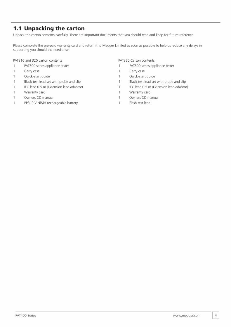
1.1 Unpacking the cartonUnpack the carton contents carefully. There are important documents that you should read and keep for future reference.
Please complete the pre-paid warranty card and return it to Megger Limited as soon as possible to help us reduce any delays in supporting you should the need arise.
PAT310 and 320 carton contents
1 PAT300 series appliance tester
1 Carry case
1 Quick-start guide
1 Black test lead set with probe and clip
1 IEC lead 0.5 m (Extension lead adaptor)
1 Warranty card
1 Owners CD manual
1 PP3 9 V NiMH rechargeable battery
PAT350 Carton contents
1 PAT300 series appliance tester
1 Carry case
1 Quick-start guide
1 Black test lead set with probe and clip
1 IEC lead 0.5 m (Extension lead adaptor)
1 Warranty card
1 Owners CD manual
1 Flash test lead
www.megger.comPAT400 Series 5
1.2 Safety Warnings
The following Safety Warnings and Precautions must be read and understood before the instrument is used. They must be observed during use.
■ For safety, only connect the PAT to a supply that is properly earthed. If in doubt, the supply should be checked by a qualified electrician.
■ Do not use the instrument if there are any signs of damage.
■ All test leads, probes and clips must be in good order, clean and with no broken or cracked insulation.
■ Probes and clips should be held behind the finger guard.
■ Test leads not used during a measurement should be disconnected from the Appliance tester.
■ For dual voltage testers, both sockets can be live simultaneously.
■ Only connect one asset to the PAT during testing.
■ Tests should be carried out in the order recommended below. An appliance that fails a test should be repaired before further testing is carried out. Recommended Sequence: 1. Earth Bond/ Continuity of the protective earth conductor (Class I devices) 2. Insulation test (or earth leakage) In addition further tests can be performed 3. Operation test 4. Leakage test
■ Only perform an operational test after the Earth bond and insulation tests have been completed, as this test operate at mains voltage.
■ During testing, ensure no hazard will exist as a result of normal running or under fault conditions.
■ During testing the unit under test (asset) should not be touched, other than using the appropriate accessories, as faulty appliances can present a shock hazard.
■ Do not touch the exposed parts of test leads during tests as hazardous voltages may be present due to potentially faulty appliance.
■ Do not touch the IEC extension lead socket pins especially during a test, as hazardous voltages may be present due to a potentially faulty appliance
■ Assets should not be routinely flash tested. Where flash testing is required, refer to further guidance on Flash testing, section 4.5.
■ Replacement fuses must be of the correct rating and type. Refer to section 6.3
■ The USB connection should only be used by approved service personnel; nothing should be connected to the USB port during testing.
■ Only use NiMH rechargeable 9 V PP3 battery, do not use a non rechargeable type as this could become dangerous if charged by the instrument.
■ Serviceable fuses should only be replaced with those that are suitably rated
■ In case of an emergency use an easily accessible power point
CAT II
Measurement category II: Equipment connected between the electrical outlets and the user’s equipment.
CAT III
Measurement category III: Equipment connected between the distribution panel and the electrical outlets.
CAT IV
Measurement category IV: Equipment connected between the origin of the low-voltage mains supply and the distribution panel.
www.megger.comPAT400 Series 6
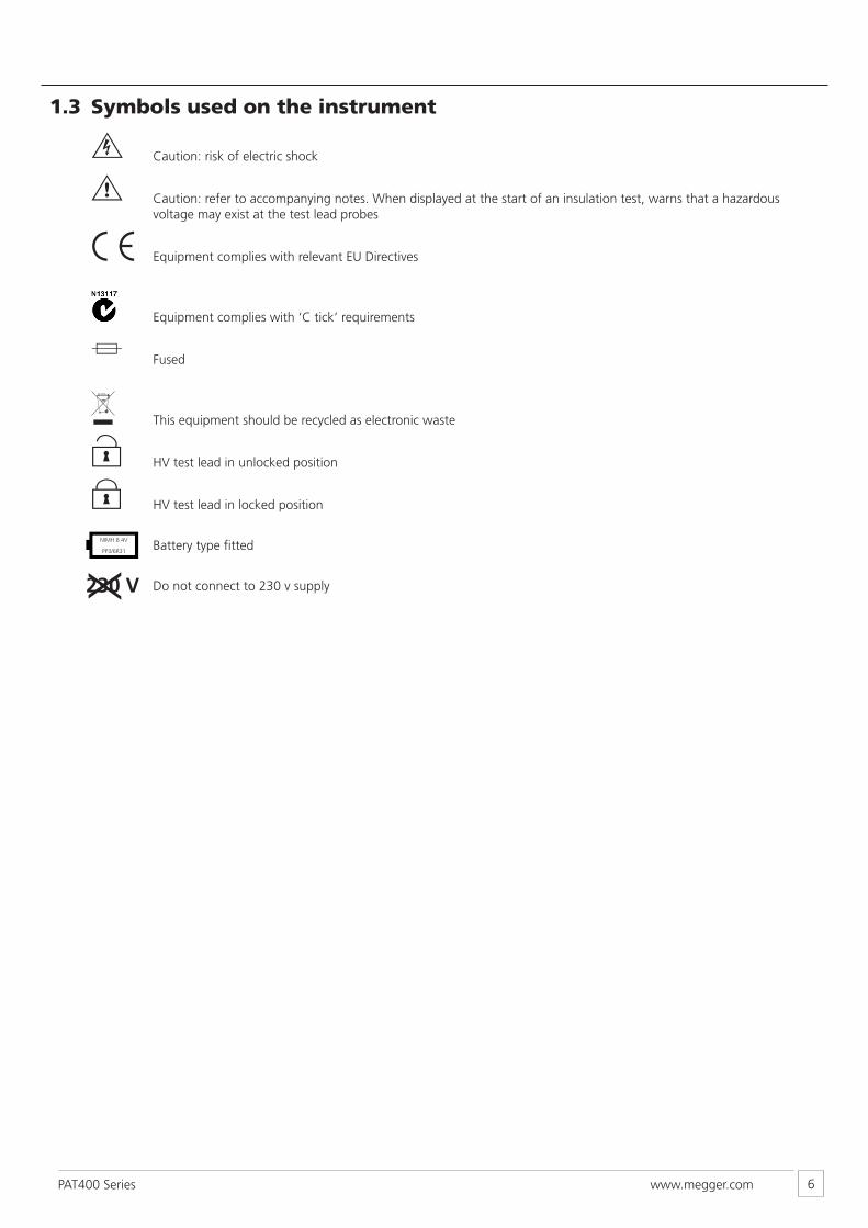
1.3 Symbols used on the instrument
F Caution: risk of electric shock
G Caution: refer to accompanying notes. When displayed at the start of an insulation test, warns that a hazardous voltage may exist at the test lead probes
c Equipment complies with relevant EU Directives
Equipment complies with ‘C tick’ requirements
f Fused
This equipment should be recycled as electronic waste
U HV test lead in unlocked position
L HV test lead in locked position
Battery type fitted
Do not connect to 230 v supply230 VX
LR6 AANIMH 8.4V
PP3/6R31
www.megger.comPAT400 Series 7
2. Getting started
2.1 Carry case
The carry case for the appliance tester has a lead storage pouch in the lid of the case when opened. This is designed for basic lead and document storage.
Further items can be stored in the pouch. If it becomes difficult to close the case, the storage pouch can be removed from inside the case and attached to the front using the straps on the reverse of the pouch.
These are passed through the D-loops on the outside of the case and secured to the underside of the pouch using the Velcro fixings.
An additional storage pouch is available from Megger Ltd for extended storage, such that there is a pouch on both the inside and outside of the carry case.
9 V PP3 rechargeable NiMH Battery is supplied- not fitted. This should be installed prior to first use. See section 6 for instructions.
www.megger.comPAT400 Series 8
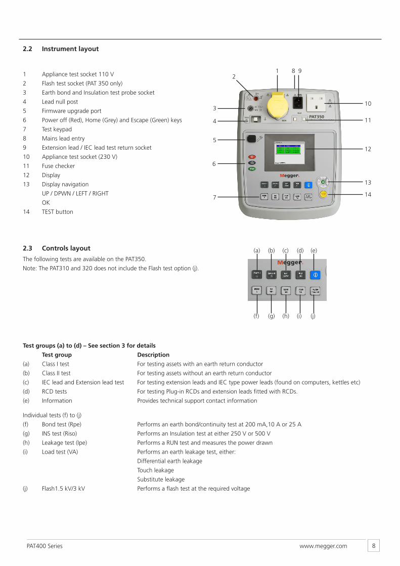
2.2 Instrument layout
1 Appliance test socket 110 V
2 Flash test socket (PAT 350 only)
3 Earth bond and Insulation test probe socket
4 Lead null post
5 Firmware upgrade port
6 Power off (Red), Home (Grey) and Escape (Green) keys
7 Test keypad
8 Mains lead entry
9 Extension lead / IEC lead test return socket
10 Appliance test socket (230 V)
11 Fuse checker
12 Display
13 Display navigation
UP / DPWN / LEFT / RIGHT
OK
14 TEST button
1 8 92
3
4
5
6
7 14
13
12
11
10
(a)
(f)
(c)
(h)
(b)
(g)
(d)
(i)
(e)
(j)
2.3 Controls layout
The following tests are available on the PAT350.
Note: The PAT310 and 320 does not include the Flash test option (j).
Test groups (a) to (d) – See section 3 for details
Test group Description
(a) Class I test For testing assets with an earth return conductor
(b) Class II test For testing assets without an earth return conductor
(c) IEC lead and Extension lead test For testing extension leads and IEC type power leads (found on computers, kettles etc)
(d) RCD tests For testing Plug-in RCDs and extension leads fitted with RCDs.
(e) Information Provides technical support contact information Individual tests (f) to (j)
(f) Bond test (Rpe) Performs an earth bond/continuity test at 200 mA,10 A or 25 A
(g) INS test (Riso) Performs an Insulation test at either 250 V or 500 V
(h) Leakage test (Ipe) Performs a RUN test and measures the power drawn
(i) Load test (VA) Performs an earth leakage test, either:
Differential earth leakage
Touch leakage
Substitute leakage
(j) Flash1.5 kV/3 kV Performs a flash test at the required voltage
www.megger.comPAT400 Series 9
2.4 Instrument start-up
Connect the instrument to a suitable electrical supply:
The appliance tester will automatically start when connected to the mains supply.
NOTE:
DO NOT connect any equipment to the PAT tester until it has been switched on and passed self test. Connected equipment will create a relay error and necessitate restarting the appliance tester by pressing the OFF button. Once switched off the power should be disconnected and reconnected.
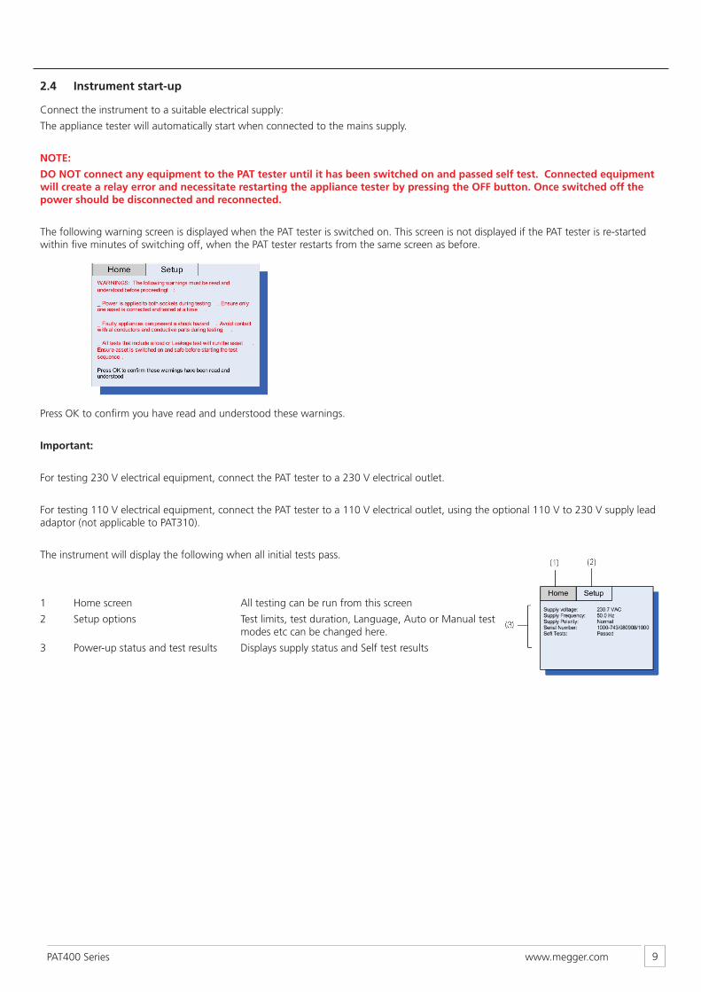
The following warning screen is displayed when the PAT tester is switched on. This screen is not displayed if the PAT tester is re-started within five minutes of switching off, when the PAT tester restarts from the same screen as before.
Press OK to confirm you have read and understood these warnings.
Important:
For testing 230 V electrical equipment, connect the PAT tester to a 230 V electrical outlet.
For testing 110 V electrical equipment, connect the PAT tester to a 110 V electrical outlet, using the optional 110 V to 230 V supply lead adaptor (not applicable to PAT310).
The instrument will display the following when all initial tests pass.
1 Home screen All testing can be run from this screen
2 Setup options Test limits, test duration, Language, Auto or Manual test modes etc can be changed here.
3 Power-up status and test results Displays supply status and Self test results
www.megger.comPAT400 Series 10
2.5 Switching off the appliance tester
To switch off the tester, press the RED off button. The display will show the message
“It is now safe to remove power”. Now the mains plug can be removed from the supply.
Failure to press the RED off button will discharge the FAST START battery un-necessarily as per section 2.5.1.
If the RED off button is pressed accidentally, pressing the button will return the PAT to normal testing mode.
2.5.1 FAST Restart
If the tester is to be moved to a new location and testing continued, simply unplug the unit from the mains supply and reconnect it in the new location. The appliance tester will enter a hibernation mode during the move and restart instantly from the point power was disconnected, without any delay.
The rechargeable 9 V NIMH battery is used to maintain hibernation status whilst unplugged. This cell is continuously charged whilst the appliance tester is connected to the mains supply.
Continuous use of the hibernation mode will discharge the battery. Only use the hibernation mode when a fast restart is required.
Should the move take longer than 5 minutes, the appliance tester will leave hibernation mode and complete a full power down.
2.6 Testing an asset
2.6.1 To run a test - (Example shows a Class I test in AUTOMATIC test mode)
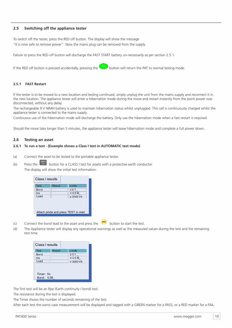
(a) Connect the asset to be tested to the portable appliance tester.
(b) Press the button for a CLASS I test for assets with a protective earth conductor.
The display will show the initial test information:
(c) Connect the bond lead to the asset and press the button to start the test.
(d) The Appliance tester will display any operational warnings as well as the measured values during the test and the remaining test time.
The first test will be an Rpe (Earth continuity / bond) test.
The resistance during the test is displayed.
The Timer shows the number of seconds remaining of the test.
After each test the worst case measurement will be displayed and tagged with a GREEN marker for a PASS, or a RED marker for a FAIL.
www.megger.comPAT400 Series 11
Note – ABORTING A TEST:
A test can be aborted at any time by pressing the button.
Each test will run automatically unless there is a manual operation required.
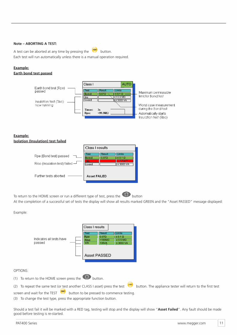
Example:
Earth bond test passed
Example:
Isolation (Insulation) test failed
To return to the HOME screen or run a different type of test, press the button
At the completion of a successful set of tests the display will show all results marked GREEN and the “Asset PASSED” message displayed:
Example:
OPTIONS:
(1) To return to the HOME screen press the button.
(2) To repeat the same test (or test another CLASS I asset) press the test button. The appliance tester will return to the first test
screen and wait for the TEST button to be pressed to commence testing.
(3) To change the test type, press the appropriate function button.
Should a test fail it will be marked with a RED tag, testing will stop and the display will show “Asset Failed”. Any fault should be made good before testing is re-started.
www.megger.comPAT400 Series 12
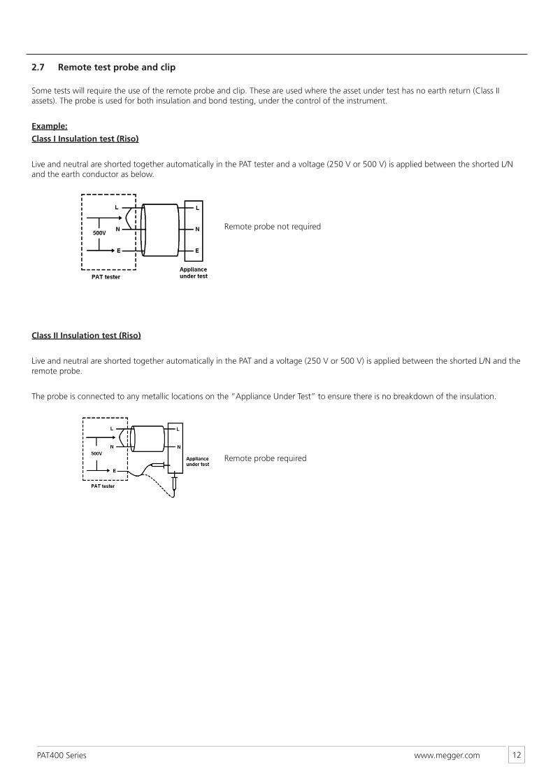
2.7 Remote test probe and clip
Some tests will require the use of the remote probe and clip. These are used where the asset under test has no earth return (Class II assets). The probe is used for both insulation and bond testing, under the control of the instrument.
Example:
Class I Insulation test (Riso)
Live and neutral are shorted together automatically in the PAT tester and a voltage (250 V or 500 V) is applied between the shorted L/N and the earth conductor as below.
Class II Insulation test (Riso)
Live and neutral are shorted together automatically in the PAT and a voltage (250 V or 500 V) is applied between the shorted L/N and the remote probe.
The probe is connected to any metallic locations on the “Appliance Under Test” to ensure there is no breakdown of the insulation.
Remote probe not required
Remote probe required
www.megger.comPAT400 Series 13
3. Test options
Each test option (button) consists of a group of tests required for that class of test. The instrument will display the tests to be completed and the status of each test as they are completed, against the set Pass limit for that test. TO change PASS limits, refer to section 5 – Setup.
The following sections show the difference between automatic and manual operation, what is displayed during each test and which connections are required during the test sequence.
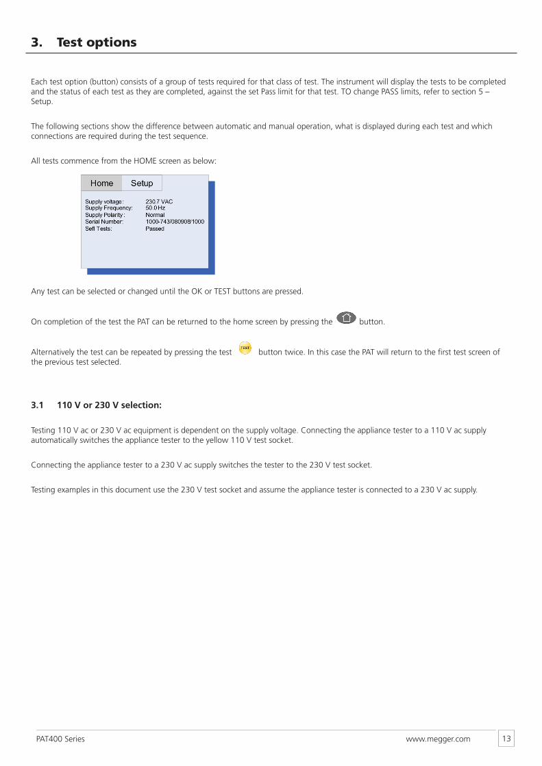
All tests commence from the HOME screen as below:
Any test can be selected or changed until the OK or TEST buttons are pressed.
On completion of the test the PAT can be returned to the home screen by pressing the button.
Alternatively the test can be repeated by pressing the test button twice. In this case the PAT will return to the first test screen of the previous test selected.
3.1 110 V or 230 V selection:
Testing 110 V ac or 230 V ac equipment is dependent on the supply voltage. Connecting the appliance tester to a 110 V ac supply automatically switches the appliance tester to the yellow 110 V test socket.
Connecting the appliance tester to a 230 V ac supply switches the tester to the 230 V test socket.
Testing examples in this document use the 230 V test socket and assume the appliance tester is connected to a 230 V ac supply.
www.megger.comPAT400 Series 14
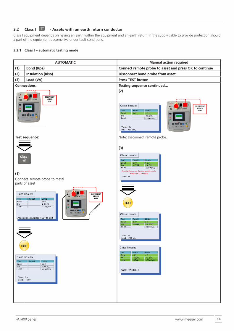
3.2 Class I - Assets with an earth return conductorClass I equipment depends on having an earth within the equipment and an earth return in the supply cable to provide protection should a part of the equipment become live under fault conditions.
3.2.1 Class I – automatic testing mode
AUTOMATIC Manual action required
(1) Bond (Rpe) Connect remote probe to asset and press OK to continue
(2) Insulation (Riso) Disconnect bond probe from asset
(3) Load (VA) Press TEST button
Connections:
Test sequence:
(1)
Connect remote probe to metal parts of asset
Testing sequence continued…
(2)
Note: Disconnect remote probe.
(3)
www.megger.comPAT400 Series 15
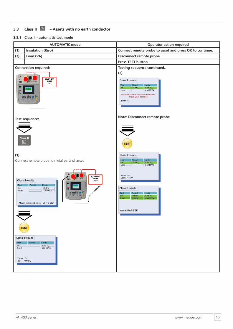
3.3 Class II – Assets with no earth conductor
3.3.1 Class II - automatic test mode
AUTOMATIC mode Operator action required
(1) Insulation (Riso) Connect remote probe to asset and press OK to continue.
(2) Load (VA) Disconnect remote probe
Press TEST button
Connection required:
Test sequence:
(1)
Connect remote probe to metal parts of asset
Testing sequence continued…
(2)
Note: Disconnect remote probe
www.megger.comPAT400 Series 16
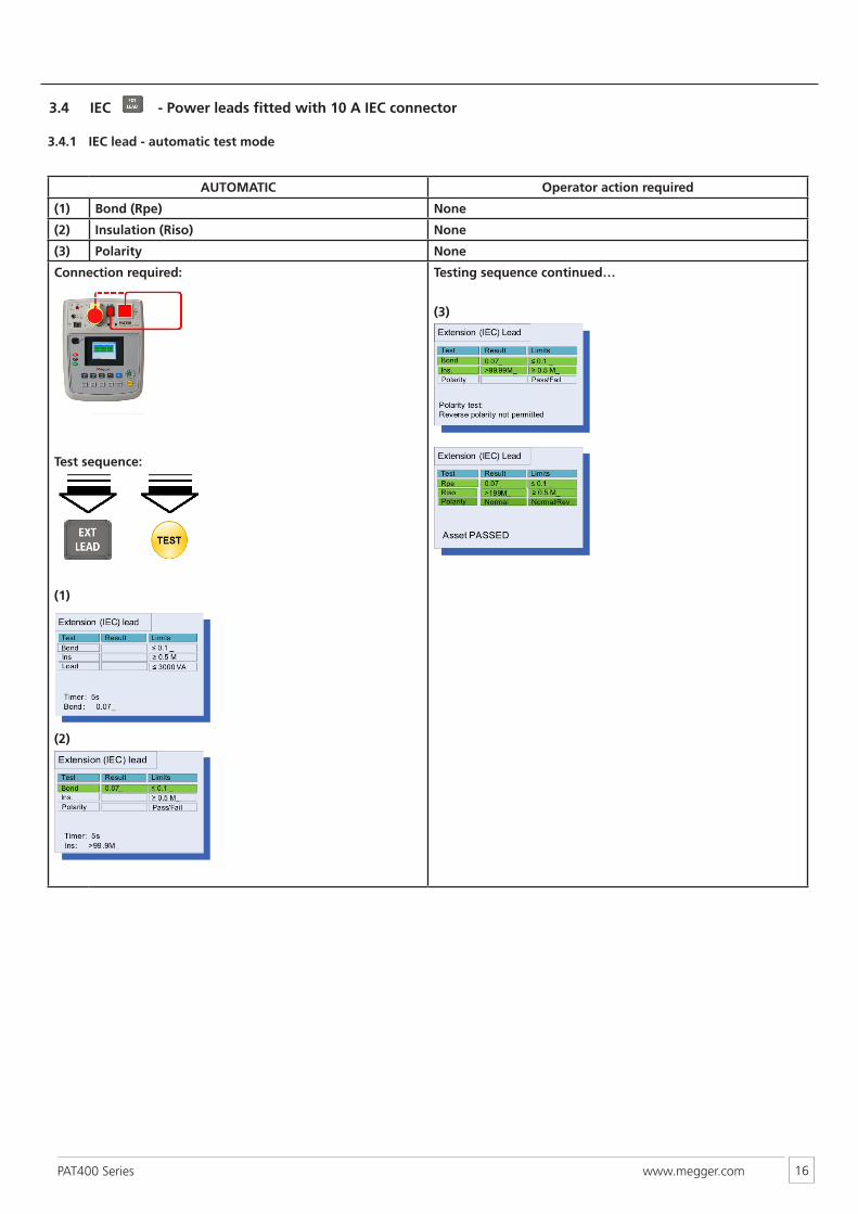
3.4 IEC - Power leads fitted with 10 A IEC connector
3.4.1 IEC lead - automatic test mode
AUTOMATIC Operator action required
(1) Bond (Rpe) None
(2) Insulation (Riso) None
(3) Polarity None
Connection required:
Test sequence:
(1)
(2)
Testing sequence continued…
(3)
www.megger.comPAT400 Series 17
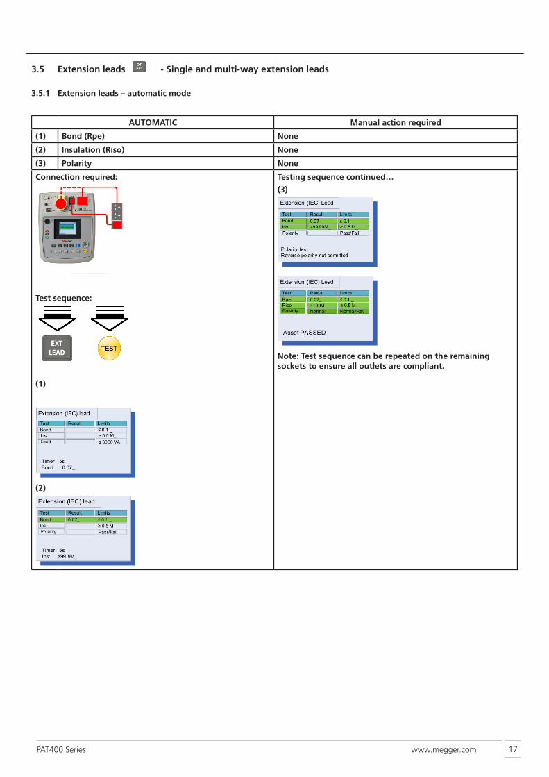
3.5 Extension leads - Single and multi-way extension leads
3.5.1 Extension leads – automatic mode
AUTOMATIC Manual action required
(1) Bond (Rpe) None
(2) Insulation (Riso) None
(3) Polarity None
Connection required:
Test sequence:
(1)
(2)
Testing sequence continued…
(3)
Note: Test sequence can be repeated on the remaining sockets to ensure all outlets are compliant.
www.megger.comPAT400 Series 18
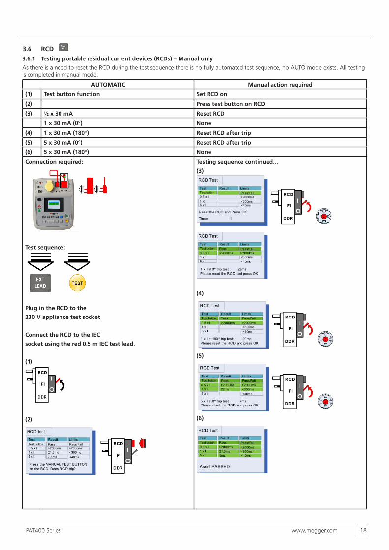
3.6 RCD 3.6.1 Testing portable residual current devices (RCDs) – Manual only
As there is a need to reset the RCD during the test sequence there is no fully automated test sequence, no AUTO mode exists. All testing is completed in manual mode.
AUTOMATIC Manual action required
(1) Test button function Set RCD on
(2) Press test button on RCD
(3) ½ x 30 mA Reset RCD
1 x 30 mA (0°) None
(4) 1 x 30 mA (180°) Reset RCD after trip
(5) 5 x 30 mA (0°) Reset RCD after trip
(6) 5 x 30 mA (180°) None
Connection required:
Test sequence:
Plug in the RCD to the
230 V appliance test socket
Connect the RCD to the IEC
socket using the red 0.5 m IEC test lead.
(1)
(2)
Testing sequence continued…
(3)
(4)
(5)
(6)
www.megger.comPAT400 Series 19
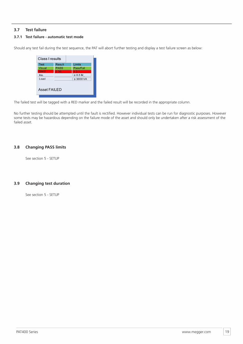
3.7 Test failure
3.7.1 Test failure - automatic test mode
Should any test fail during the test sequence, the PAT will abort further testing and display a test failure screen as below:
The failed test will be tagged with a RED marker and the failed result will be recorded in the appropriate column.
No further testing should be attempted until the fault is rectified. However individual tests can be run for diagnostic purposes. However some tests may be hazardous depending on the failure mode of the asset and should only be undertaken after a risk assessment of the failed asset.
3.8 Changing PASS limits
See section 5 - SETUP
3.9 Changing test duration
See section 5 - SETUP
www.megger.comPAT400 Series 20
4. Individual tests – Quick tests:
These tests are individual tests and perform a single type of test. Where several options exist under the one function (such as Bond with 25 A, 10 A or 200 mA) then those options will be available for selection.
Notes:
There is no automatic mode for these tests.
Pass fail limits are not enabled. Actual measurement values are displayed during and at the completion of testing.
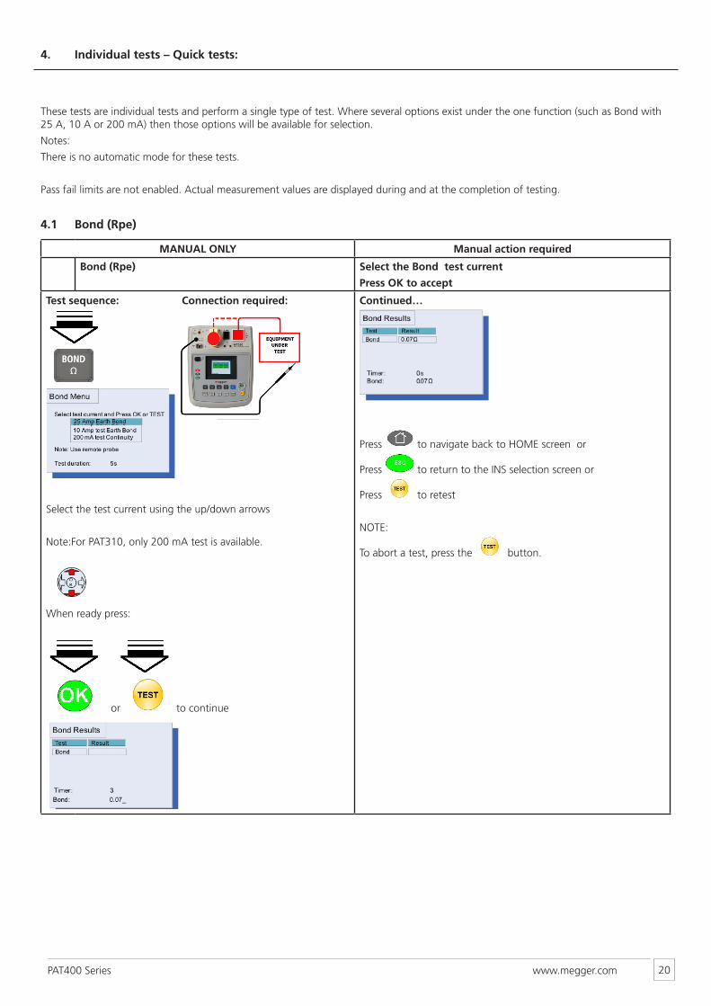
4.1 Bond (Rpe)
MANUAL ONLY Manual action required
Bond (Rpe) Select the Bond test current
Press OK to accept
Test sequence: Connection required:
Select the test current using the up/down arrows
Note:For PAT310, only 200 mA test is available.
When ready press:
or to continue
Continued…
Press to navigate back to HOME screen or
Press to return to the INS selection screen or
Press to retest
NOTE:
To abort a test, press the button.
www.megger.comPAT400 Series 21
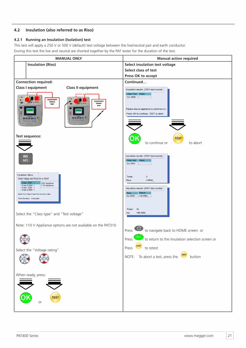
4.2 Insulation (also referred to as Riso)
4.2.1 Running an Insulation (Isolation) test
This test will apply a 250 V or 500 V (default) test voltage between the live/neutral pair and earth conductor.
During this test the live and neutral are shorted together by the PAT tester for the duration of the test.
MANUAL ONLY Manual action required
Insulation (Riso) Select insulation test voltage
Select class of test
Press OK to accept
Connection required:
Class I equipment Class II equipment
Test sequence:
Select the “Class type” and “Test voltage”
Note: 110 V Appliance options are not available on the PAT310
Select the “Voltage rating”
When ready, press:
or
Continued…
to continue or to abort
Press to navigate back to HOME screen or
Press to return to the Insulation selection screen or
Press to retest
NOTE: To abort a test, press the button
www.megger.comPAT400 Series 22
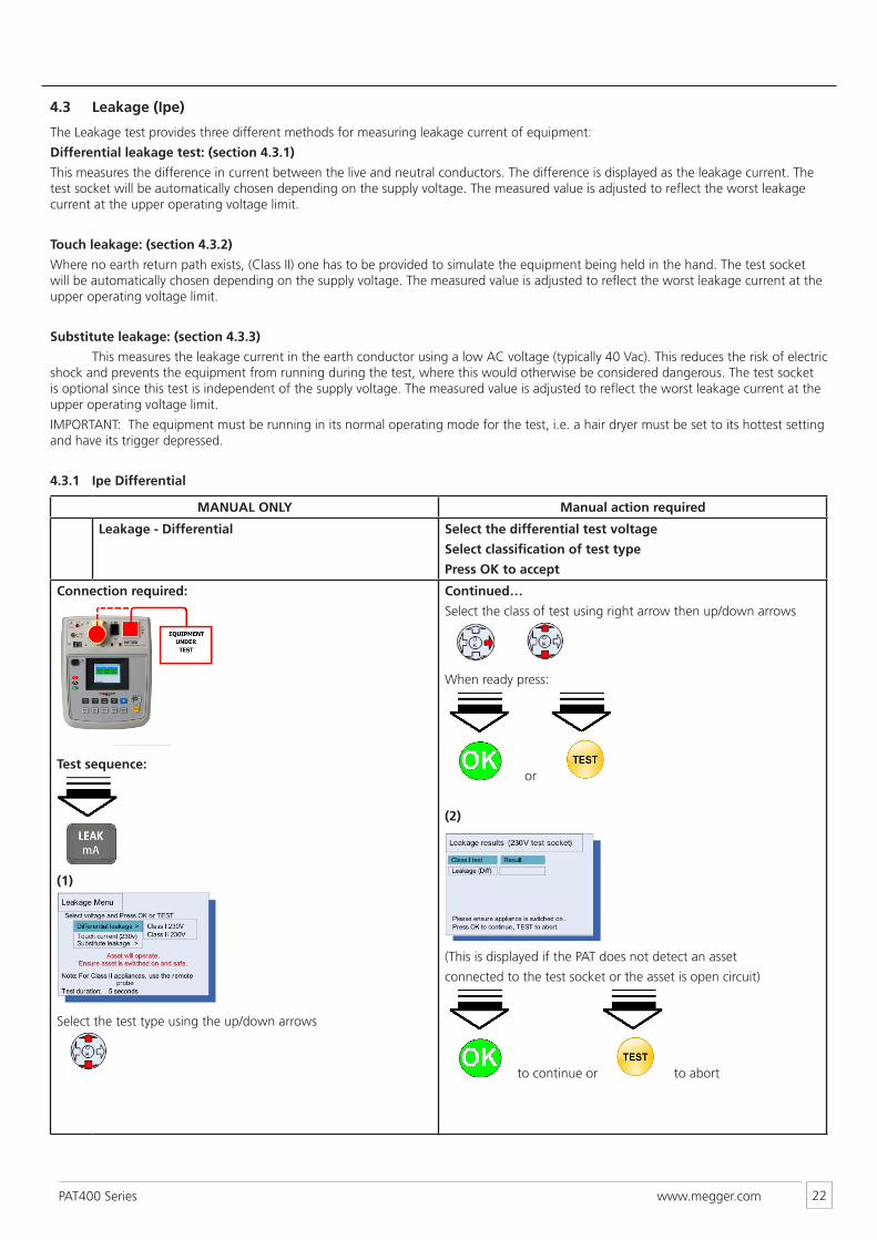
4.3 Leakage (Ipe)
The Leakage test provides three different methods for measuring leakage current of equipment:
Differential leakage test: (section 4.3.1)
This measures the difference in current between the live and neutral conductors. The difference is displayed as the leakage current. The test socket will be automatically chosen depending on the supply voltage. The measured value is adjusted to reflect the worst leakage current at the upper operating voltage limit.
Touch leakage: (section 4.3.2)
Where no earth return path exists, (Class II) one has to be provided to simulate the equipment being held in the hand. The test socket will be automatically chosen depending on the supply voltage. The measured value is adjusted to reflect the worst leakage current at the upper operating voltage limit.
Substitute leakage: (section 4.3.3)
This measures the leakage current in the earth conductor using a low AC voltage (typically 40 Vac). This reduces the risk of electric shock and prevents the equipment from running during the test, where this would otherwise be considered dangerous. The test socket is optional since this test is independent of the supply voltage. The measured value is adjusted to reflect the worst leakage current at the upper operating voltage limit.
IMPORTANT: The equipment must be running in its normal operating mode for the test, i.e. a hair dryer must be set to its hottest setting and have its trigger depressed.
4.3.1 Ipe Differential
MANUAL ONLY Manual action required
Leakage - Differential Select the differential test voltage
Select classification of test type
Press OK to accept
Connection required:
Test sequence:
(1)
Select the test type using the up/down arrows
Continued…
Select the class of test using right arrow then up/down arrows
When ready press:
or
(2)
(This is displayed if the PAT does not detect an asset
connected to the test socket or the asset is open circuit)
to continue or to abort
www.megger.comPAT400 Series 23
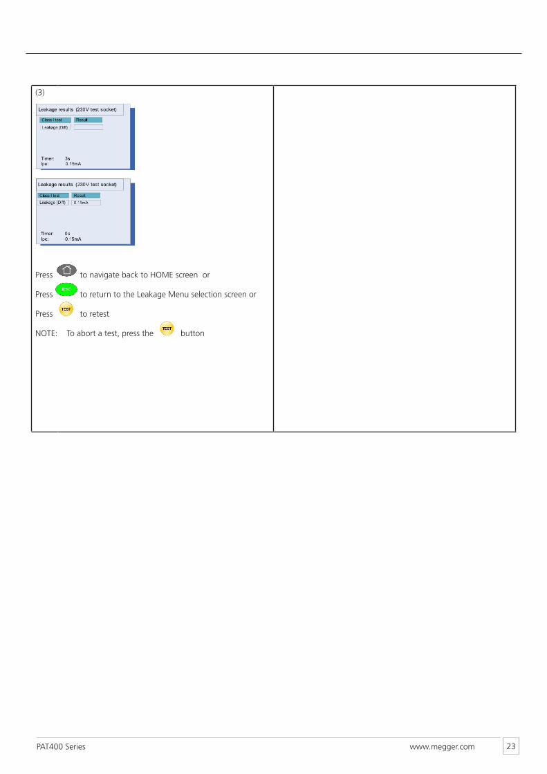
(3)
Press to navigate back to HOME screen or
Press to return to the Leakage Menu selection screen or
Press to retest
NOTE: To abort a test, press the button
www.megger.comPAT400 Series 24
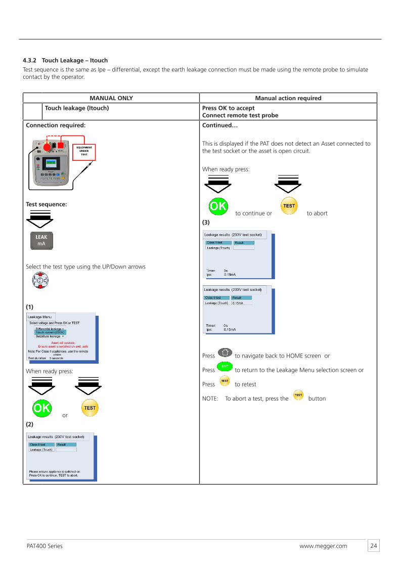
4.3.2 Touch Leakage – Itouch
Test sequence is the same as Ipe – differential, except the earth leakage connection must be made using the remote probe to simulate contact by the operator.
MANUAL ONLY Manual action required
Touch leakage (Itouch) Press OK to accept Connect remote test probe
Connection required:
Test sequence:
Select the test type using the UP/Down arrows
(1)
When ready press:
or
(2)
Continued…
This is displayed if the PAT does not detect an Asset connected to the test socket or the asset is open circuit.
When ready press:
to continue or to abort
(3)
Press to navigate back to HOME screen or
Press to return to the Leakage Menu selection screen or
Press to retest
NOTE: To abort a test, press the button
www.megger.comPAT400 Series 25
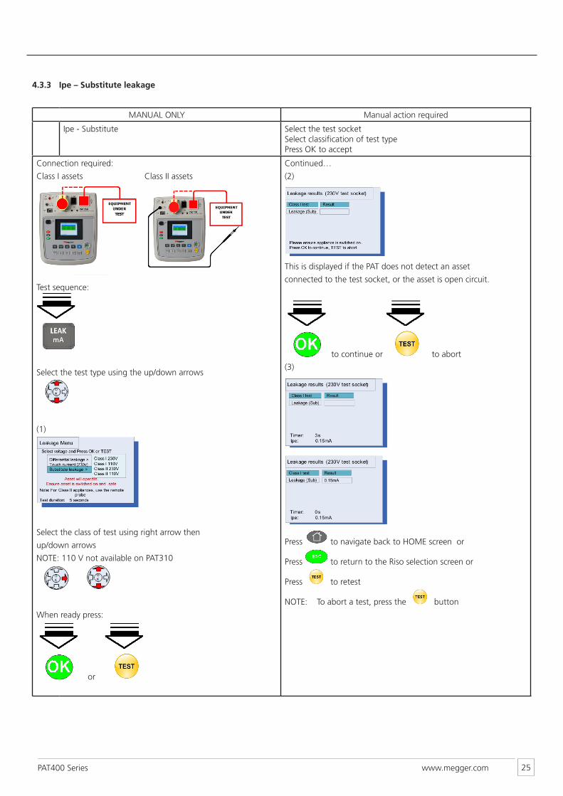
4.3.3 Ipe – Substitute leakage
MANUAL ONLY Manual action required
Ipe - Substitute Select the test socket Select classification of test type Press OK to accept
Connection required:
Class I assets Class II assets
Test sequence:
Select the test type using the up/down arrows
(1)
Select the class of test using right arrow then
up/down arrows
NOTE: 110 V not available on PAT310
When ready press:
or
Continued…
(2)
This is displayed if the PAT does not detect an asset
connected to the test socket, or the asset is open circuit.
to continue or to abort
(3)
Press to navigate back to HOME screen or
Press to return to the Riso selection screen or
Press to retest
NOTE: To abort a test, press the button
www.megger.comPAT400 Series 26
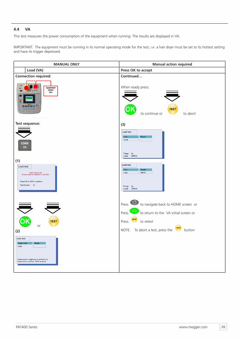
4.4 VA
This test measures the power consumption of the equipment when running. The results are displayed in VA.
IMPORTANT: The equipment must be running in its normal operating mode for the test, i.e. a hair dryer must be set to its hottest setting and have its trigger depressed.
MANUAL ONLY Manual action required
Load (VA) Press OK to accept
Connection required:
Test sequence:
(1)
or
(2)
Continued…
When ready press:
to continue or to abort
(3)
Press to navigate back to HOME screen or
Press to return to the VA initial screen or
Press to retest
NOTE: To abort a test, press the button
www.megger.comPAT400 Series 27
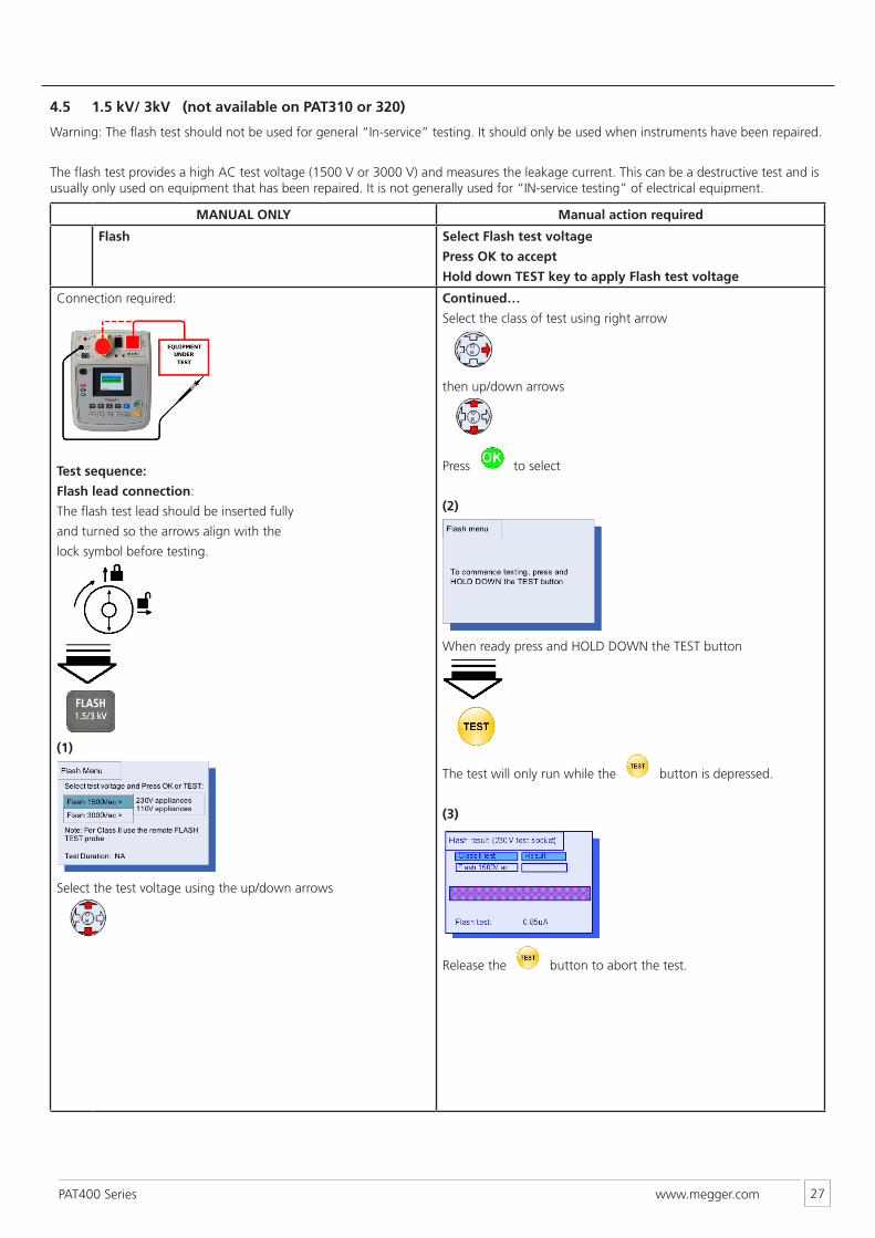
4.5 1.5 kV/ 3kV (not available on PAT310 or 320)
Warning: The flash test should not be used for general “In-service” testing. It should only be used when instruments have been repaired.
The flash test provides a high AC test voltage (1500 V or 3000 V) and measures the leakage current. This can be a destructive test and is usually only used on equipment that has been repaired. It is not generally used for “IN-service testing” of electrical equipment.
MANUAL ONLY Manual action required
Flash Select Flash test voltage
Press OK to accept
Hold down TEST key to apply Flash test voltage
Connection required:
Test sequence:
Flash lead connection:
The flash test lead should be inserted fully
and turned so the arrows align with the
lock symbol before testing.
(1)
Select the test voltage using the up/down arrows
Continued…
Select the class of test using right arrow
then up/down arrows
Press to select
(2)
When ready press and HOLD DOWN the TEST button
The test will only run while the button is depressed.
(3)
Release the button to abort the test.
www.megger.comPAT400 Series 28
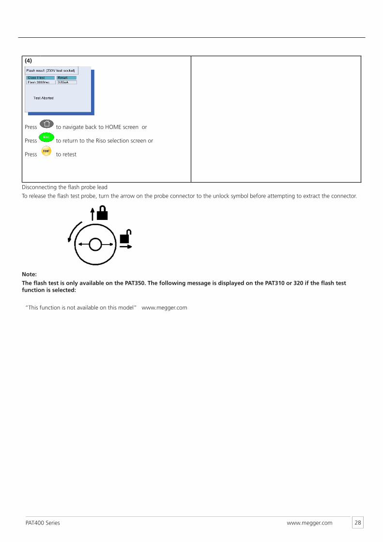
(4)
Press to navigate back to HOME screen or
Press to return to the Riso selection screen or
Press to retest
Disconnecting the flash probe lead
To release the flash test probe, turn the arrow on the probe connector to the unlock symbol before attempting to extract the connector.
Note:
The flash test is only available on the PAT350. The following message is displayed on the PAT310 or 320 if the flash test function is selected:
“This function is not available on this model” www.megger.com
www.megger.comPAT400 Series 29
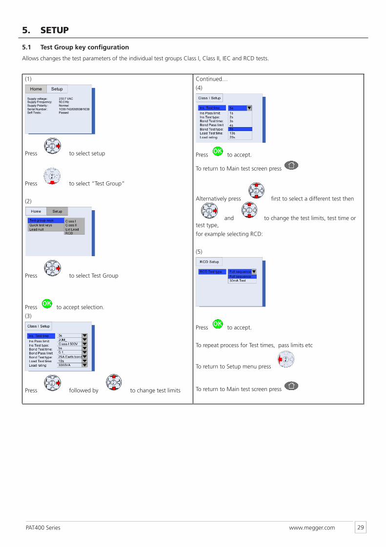
5. SETUP
5.1 Test Group key configuration
Allows changes the test parameters of the individual test groups Class I, Class II, IEC and RCD tests.
(1)
Press to select setup
Press to select “Test Group”
(2)
Press to select Test Group
Press to accept selection.
(3)
Press followed by to change test limits
Continued…
(4)
Press to accept.
To return to Main test screen press
Alternatively press first to select a different test then
and to change the test limits, test time or test type,
for example selecting RCD:
(5)
Press to accept.
To repeat process for Test times, pass limits etc
To return to Setup menu press
To return to Main test screen press
www.megger.comPAT400 Series 30
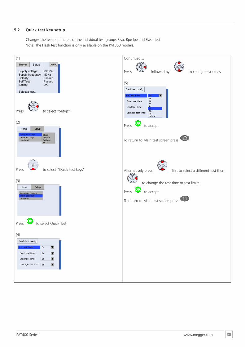
5.2 Quick test key setup
Changes the test parameters of the individual test groups Riso, Rpe Ipe and Flash test.
Note: The Flash test function is only available on the PAT350 models.
(1)
Press to select “Setup”
(2)
Press to select “Quick test keys”
(3)
Press to select Quick Test
(4)
Continued…
Press followed by to change test times
(5)
Press to accept
To return to Main test screen press
Alternatively press first to select a different test then
to change the test time or test limits.
Press to accept
To return to Main test screen press
www.megger.comPAT400 Series 31
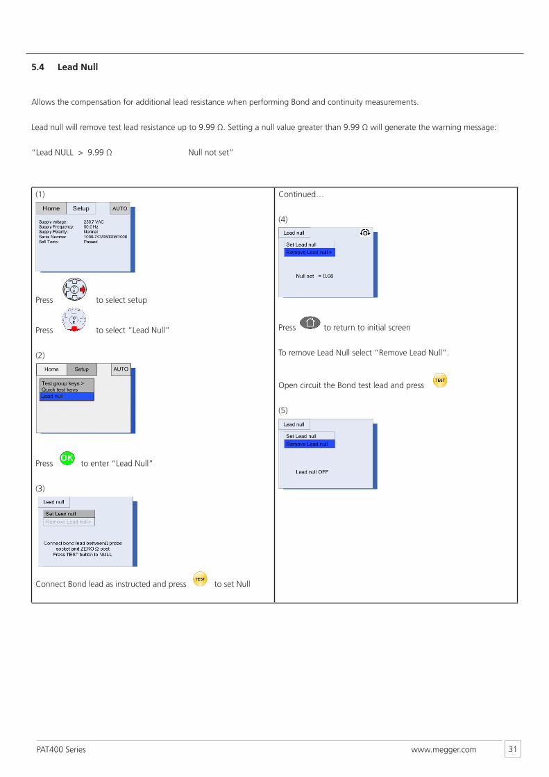
5.4 Lead Null
Allows the compensation for additional lead resistance when performing Bond and continuity measurements.
Lead null will remove test lead resistance up to 9.99 Ω. Setting a null value greater than 9.99 Ω will generate the warning message:
“Lead NULL > 9.99 Ω Null not set”
(1)
Press to select setup
Press to select “Lead Null”
(2)
Press to enter “Lead Null”
(3)
Connect Bond lead as instructed and press to set Null
Continued…
(4)
Press to return to initial screen
To remove Lead Null select “Remove Lead Null”.
Open circuit the Bond test lead and press
(5)
www.megger.comPAT400 Series 32
6. Battery and fuses
6.1 Battery function
The PAT300 series are mains powered instruments. However a 9 V PP3 rechargeable NiMH battery is fitted to allow fast restart should the PAT be unplugged and reconnected to an electrical supply in less than 5 minutes.
The PAT tester will operate with a discharged battery or no battery fitted, but will perform a full power-up sequence when re-connected to a supply.
The battery is continually charged whilst the Appliance tester is operating. Only fit NiMH rechargeable batteries.
Low battery is indicated by the battery warning in the main screen.
Warning: Do not switch on the instrument or connect test leads with the battery cover removed.
Only use NiMH rechargeable battery, other types may cause battery explosion.
6.2 Battery replacement
Warning: Do not switch the instrument on with the battery cover removed or test leads connected.
1. Disconnect any test leads from the instrument.
2. Switch off the instrument and disconnect (the instrument) from any electrical circuits.
3. Remove the battery cover with a small crosshead screwdriver.
4. Remove the old battery and refit a new one, observing the terminal polarity.
5. Replace the cover and retaining screw.
Note: Battery cells should not be left in an instrument which may remain unused for an extended period.
Warning: Only use NiMH rechargeable cells. It is dangerous to fit alkaline cells which could explode or catch fire.
6.3 Fuse replacementWarning: Do not switch the instrument on with the fuse cover removed or test leads connected.
1. Disconnect any test leads from the instrument.
2. Switch off the instrument and disconnect (the instrument) from any electrical circuits.
3. Remove the fuse cover with a small crosshead screwdriver.
4. Replace the blown fuse with the correct type and rating, e.g. 5 x 20 mm 250 V, 100 mA, 1.5 kA high breaking capacity (HBC) type.
5. Replace the fuse cover
The PAT300 series instruments require very little maintenance. Instrument and test leads should be checked before use to ensure there is no damage.
When necessary, the instrument can be cleaned with a damp cloth or Isopropyl alcohol.
7. Care and maintenance
www.megger.comPAT400 Series 33
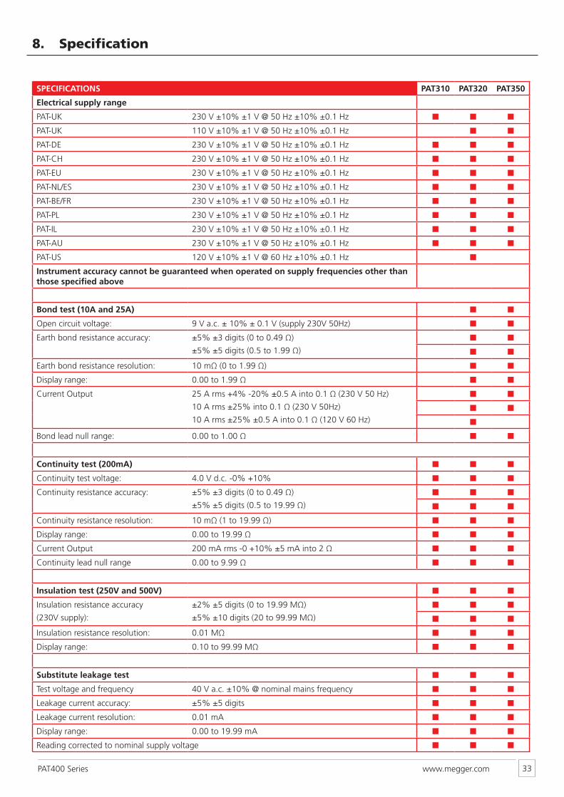
8. Specification
SPECIFICATIONS PAT310 PAT320 PAT350
Electrical supply range
PAT-UK 230 V ±10% ±1 V @ 50 Hz ±10% ±0.1 Hz ■ ■ ■
PAT-UK 110 V ±10% ±1 V @ 50 Hz ±10% ±0.1 Hz ■ ■
PAT-DE 230 V ±10% ±1 V @ 50 Hz ±10% ±0.1 Hz ■ ■ ■
PAT-CH 230 V ±10% ±1 V @ 50 Hz ±10% ±0.1 Hz ■ ■ ■
PAT-EU 230 V ±10% ±1 V @ 50 Hz ±10% ±0.1 Hz ■ ■ ■
PAT-NL/ES 230 V ±10% ±1 V @ 50 Hz ±10% ±0.1 Hz ■ ■ ■
PAT-BE/FR 230 V ±10% ±1 V @ 50 Hz ±10% ±0.1 Hz ■ ■ ■
PAT-PL 230 V ±10% ±1 V @ 50 Hz ±10% ±0.1 Hz ■ ■ ■
PAT-IL 230 V ±10% ±1 V @ 50 Hz ±10% ±0.1 Hz ■ ■ ■
PAT-AU 230 V ±10% ±1 V @ 50 Hz ±10% ±0.1 Hz ■ ■ ■
PAT-US 120 V ±10% ±1 V @ 60 Hz ±10% ±0.1 Hz ■
Instrument accuracy cannot be guaranteed when operated on supply frequencies other than those specified above
Bond test (10A and 25A) ■ ■
Open circuit voltage: 9 V a.c. ± 10% ± 0.1 V (supply 230V 50Hz) ■ ■
Earth bond resistance accuracy: ±5% ±3 digits (0 to 0.49 Ω)
±5% ±5 digits (0.5 to 1.99 Ω)
■ ■
■ ■
Earth bond resistance resolution: 10 mΩ (0 to 1.99 Ω) ■ ■
Display range: 0.00 to 1.99 Ω ■ ■
Current Output 25 A rms +4% -20% ±0.5 A into 0.1 Ω (230 V 50 Hz)
10 A rms ±25% into 0.1 Ω (230 V 50Hz)
10 A rms ±25% ±0.5 A into 0.1 Ω (120 V 60 Hz)
■ ■
■ ■
■
Bond lead null range: 0.00 to 1.00 Ω ■ ■
Continuity test (200mA) ■ ■ ■
Continuity test voltage: 4.0 V d.c. -0% +10% ■ ■ ■
Continuity resistance accuracy: ±5% ±3 digits (0 to 0.49 Ω)
±5% ±5 digits (0.5 to 19.99 Ω)
■ ■ ■
■ ■ ■
Continuity resistance resolution: 10 mΩ (1 to 19.99 Ω) ■ ■ ■
Display range: 0.00 to 19.99 Ω ■ ■ ■
Current Output 200 mA rms -0 +10% ±5 mA into 2 Ω ■ ■ ■
Continuity lead null range 0.00 to 9.99 Ω ■ ■ ■
Insulation test (250V and 500V) ■ ■ ■
Insulation resistance accuracy
(230V supply):
±2% ±5 digits (0 to 19.99 MΩ)
±5% ±10 digits (20 to 99.99 MΩ)
■ ■ ■
■ ■ ■
Insulation resistance resolution: 0.01 MΩ ■ ■ ■
Display range: 0.10 to 99.99 MΩ ■ ■ ■
Substitute leakage test ■ ■ ■
Test voltage and frequency 40 V a.c. ±10% @ nominal mains frequency ■ ■ ■
Leakage current accuracy: ±5% ±5 digits ■ ■ ■
Leakage current resolution: 0.01 mA ■ ■ ■
Display range: 0.00 to 19.99 mA ■ ■ ■
Reading corrected to nominal supply voltage ■ ■ ■
www.megger.comPAT400 Series 34
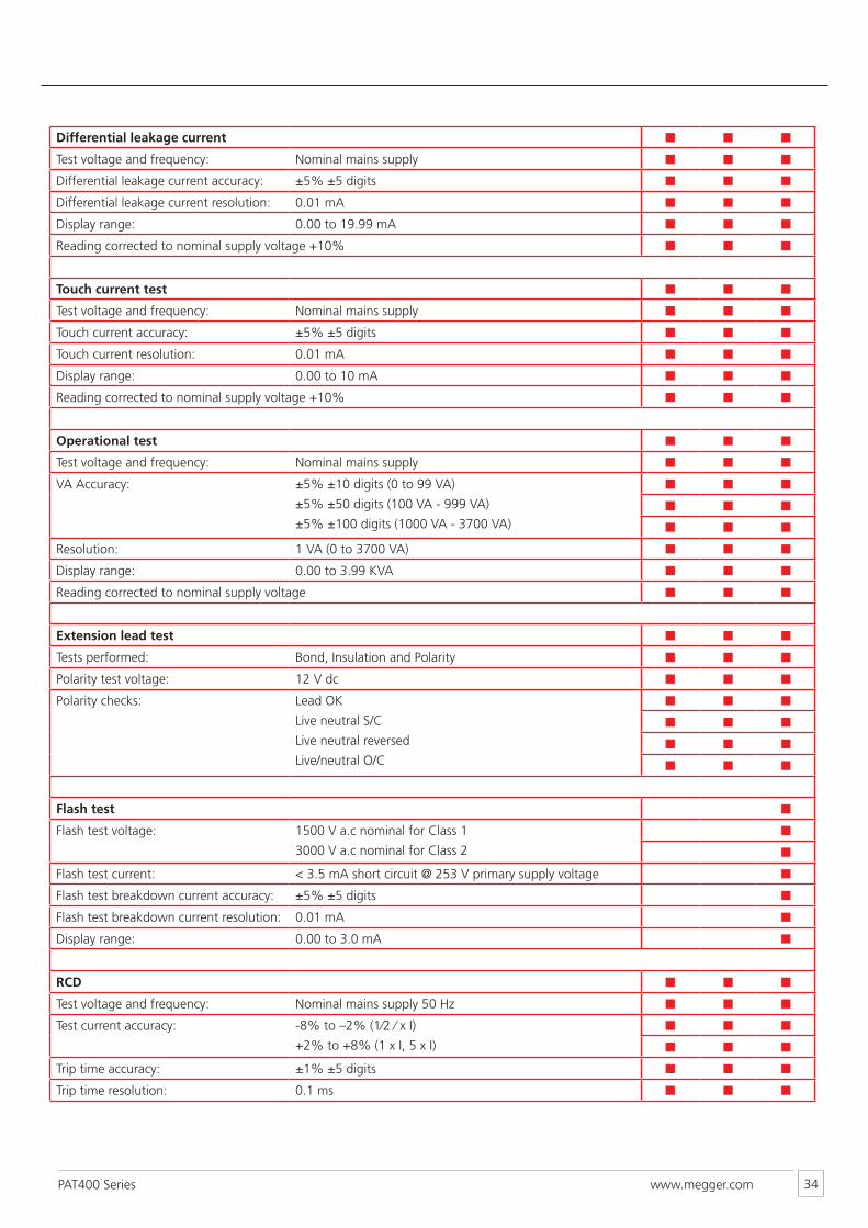
Differential leakage current ■ ■ ■
Test voltage and frequency: Nominal mains supply ■ ■ ■
Differential leakage current accuracy: ±5% ±5 digits ■ ■ ■
Differential leakage current resolution: 0.01 mA ■ ■ ■
Display range: 0.00 to 19.99 mA ■ ■ ■
Reading corrected to nominal supply voltage +10% ■ ■ ■
Touch current test ■ ■ ■
Test voltage and frequency: Nominal mains supply ■ ■ ■
Touch current accuracy: ±5% ±5 digits ■ ■ ■
Touch current resolution: 0.01 mA ■ ■ ■
Display range: 0.00 to 10 mA ■ ■ ■
Reading corrected to nominal supply voltage +10% ■ ■ ■
Operational test ■ ■ ■
Test voltage and frequency: Nominal mains supply ■ ■ ■
VA Accuracy: ±5% ±10 digits (0 to 99 VA)
±5% ±50 digits (100 VA - 999 VA)
±5% ±100 digits (1000 VA - 3700 VA)
■ ■ ■
■ ■ ■
■ ■ ■
Resolution: 1 VA (0 to 3700 VA) ■ ■ ■
Display range: 0.00 to 3.99 KVA ■ ■ ■
Reading corrected to nominal supply voltage ■ ■ ■
Extension lead test ■ ■ ■
Tests performed: Bond, Insulation and Polarity ■ ■ ■
Polarity test voltage: 12 V dc ■ ■ ■
Polarity checks: Lead OK
Live neutral S/C
Live neutral reversed
Live/neutral O/C
■ ■ ■
■ ■ ■
■ ■ ■
■ ■ ■
Flash test ■
Flash test voltage: 1500 V a.c nominal for Class 1
3000 V a.c nominal for Class 2
■
■
Flash test current: < 3.5 mA short circuit @ 253 V primary supply voltage ■
Flash test breakdown current accuracy: ±5% ±5 digits ■
Flash test breakdown current resolution: 0.01 mA ■
Display range: 0.00 to 3.0 mA ■
RCD ■ ■ ■
Test voltage and frequency: Nominal mains supply 50 Hz ■ ■ ■
Test current accuracy: -8% to –2% (1⁄2 ⁄ x I)
+2% to +8% (1 x I, 5 x I)
■ ■ ■
■ ■ ■
Trip time accuracy: ±1% ±5 digits ■ ■ ■
Trip time resolution: 0.1 ms ■ ■ ■
www.megger.comPAT400 Series 35
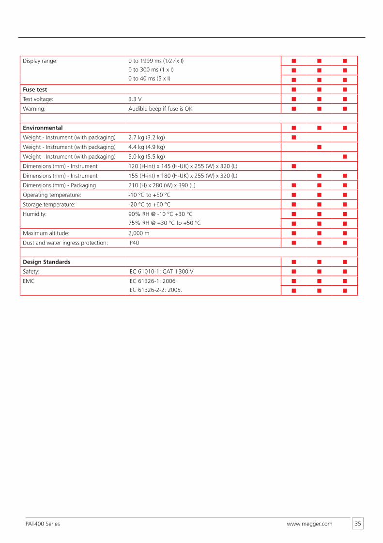
Display range: 0 to 1999 ms (1⁄2 ⁄ x I)
0 to 300 ms (1 x I)
0 to 40 ms (5 x I)
■ ■ ■
■ ■ ■
■ ■ ■
Fuse test ■ ■ ■
Test voltage: 3.3 V ■ ■ ■
Warning: Audible beep if fuse is OK ■ ■ ■
Environmental ■ ■ ■
Weight - Instrument (with packaging) 2.7 kg (3.2 kg) ■
Weight - Instrument (with packaging) 4.4 kg (4.9 kg) ■
Weight - Instrument (with packaging) 5.0 kg (5.5 kg) ■
Dimensions (mm) - Instrument 120 (H-int) x 145 (H-UK) x 255 (W) x 320 (L) ■
Dimensions (mm) - Instrument 155 (H-int) x 180 (H-UK) x 255 (W) x 320 (L) ■ ■
Dimensions (mm) - Packaging 210 (H) x 280 (W) x 390 (L) ■ ■ ■
Operating temperature: -10 °C to +50 °C ■ ■ ■
Storage temperature: -20 °C to +60 °C ■ ■ ■
Humidity: 90% RH @ -10 °C +30 °C
75% RH @ +30 °C to +50 °C
■ ■ ■
■ ■ ■
Maximum altitude: 2,000 m ■ ■ ■
Dust and water ingress protection: IP40 ■ ■ ■
Design Standards ■ ■ ■
Safety: IEC 61010-1: CAT II 300 V ■ ■ ■
EMC IEC 61326-1: 2006
IEC 61326-2-2: 2005.
■ ■ ■
■ ■ ■
www.megger.comPAT400 Series 36
9. Repair and Warranty
The instrument contains static sensitive devices, and care must be taken in handling the printed circuit board. If an instrument’s protection has been impaired it should not be used, but sent for repair by suitably trained and qualified personnel. The protection is likely to be impaired if for example, it shows visible damage, fails to perform the intended measurements, has been subjected to prolonged storage under unfavourable conditions, or has been subjected to severe transport stresses.
NEW INSTRUMENTS ARE GUARANTEED FOR 1 YEAR FROM THE DATE OF PURCHASE BY THE USER.
Note: Any unauthorized prior repair or adjustment will automatically invalidate the Warranty.
CALIBRATION, REPAIR AND SPARE PARTSFor service requirements for Megger Instruments contact:
Megger Limited
Archcliffe Road
Dover Kent, CT17 9EN
England
Tel: +44 (0) 1304 502100
Fax: +44 (0) 1304 207342
or Megger
Valley Forge Corporate Centre
2621 Van Buren Avenue
Norristown, PA 19403,
USA
Tel: +1 (610) 676-8500
Fax: +1 (610) 676-8610
Megger operate fully traceable calibration and repair facilities, ensuring your instrument continues to provide the high standard of performance and workmanship you expect. These facilities are complemented by a worldwide network of approved repair and calibration companies to offer excellent in-service care for your Megger products.
Returning your product to Megger - UK and USA service centres
1. When an instrument requires recalibration, or in the event of a repair being necessary, a Returns Authorisation (RA) number must first be obtained from one of the addresses shown above. You will be asked to provide the following information to enable the Service Department to prepare in advance for receipt of your instrument, and to provide the best possible service to you.
• Model, e.g. PAT300.
• Serial number, to be found on the underside of the case or on the calibration certificate.
• Reason for return, e.g. calibration required, or repair.
• Details of the fault if the instrument is to be repaired.
2. Make a note of the RA number. A returns label can be emailed or faxed to you if you wish.
3. Pack the instrument carefully to prevent damage in transit.
4. Ensure the returns label is attached, or that the RA number is clearly marked on the outside of the package and on any correspondence, before sending the instrument, freight paid, to Megger. Copies of the original purchase invoice and packing note should be sent simultaneously by airmail to expedite clearance through customs. In the case of instruments requiring repair outside the warranty period, an immediate quotation can be provided when obtaining the RA number.
5. You may track the progress of your return on line at www.megger.com
Approved Service CentresA list of Approved Service Centres may be obtained from the UK address above, or from Megger’s website at www.megger.com

MEGGER LIMITED ARCHCLIFFE ROAD DOVER KENT, CT17 9EN ENGLAND TEL: +44 (0) 1304 502100 FAX: +44 (0) 1304 207342
MEGGER 4271 BRONZE WAYDALLASTX 75237-1017 U.S.A.TEL: +1 (800) 723-2861 (U.S.A. ONLY)TEL: +1 (214) 330-3203 (INTERNATIONAL)FAX: +1 (214) 337-3038
THIS INSTRUMENT IS MANUFACTURED IN THE UNITED KINGDOM.THE COMPANY RESERVES THE RIGHT TO CHANGE THE SPECIFICATION OR DESIGN WITHOUT PRIOR NOTICE.
MEGGER IS A REGISTERED TRADEMARK.
PAT300-UG_EN_V09WWW.MEGGER.COM
MEGGERVALLEY FORGE CORPORATE CENTRE2621 VAN BUREN AVENUENORRISTOWN, PA 19403, USATEL: +1 (610) 676-8500FAX: +1 (610) 676-8610
MEGGER SARLZ.A. DU BUISSON DE LA COULDRE23 RUE EUGÈNE HENAFF 78190 TRAPPESFRANCETEL : +33 (1) 30.16.08.90FAX : +33 (1) 34.61.23.77
WW
W.M
EG
GER
.CO
M