Embed Size (px)
Citation preview

PassiveVLC: Enabling Practical Visible Light BackscatterCommunication for Battery-free IoT Applications
Xieyang Xu†, Yang Shen†, Junrui Yang♯, Chenren Xu†, Guobin Shen§, Guojun Chen†, Yunzhe Ni†∗
†Peking University ♯Stanford University §Zepp Labs, Inc.{xy.xu, sy2006, chenren, leochan, yunzhe.ni}@pku.edu.cn [email protected] [email protected]
ABSTRACTThis paper investigates the feasibility of practical backscatter com-munication using visible light for battery-free IoT applications.Based on the idea of modulating the light retroreflection with acommercial LCD shutter, we effectively synthesize these off-the-shelf optical components into a sub-mW low power visible lightpassive transmitter along with a retroreflecting uplink design dedi-cated for power constrained mobile/IoT devices. On top of that, wedesign, implement and evaluate PassiveVLC, a novel visible lightbackscatter communication system. PassiveVLC system enablesa battery-free tag device to perform passive communication withthe illuminating LEDs over the same light carrier and thus offersseveral favorable features including battery-free, sniff-proof, andbiologically friendly for human-centric use cases. Experimental re-sults from our prototyped system show that PassiveVLC is flexiblewith tag orientation, robust to ambient lighting conditions, andcan achieve up to 1 kbps uplink speed. Link budget analysis andtwo proof-of-concept applications are developed to demonstratePassiveVLC’s efficacy and practicality.
CCS CONCEPTS•Hardware→Wireless devices; • Computer systems organi-zation → Embedded systems;
KEYWORDSVisible Light Communication, Passive Communication, Backscatter,Battery-free, Internet of Things, Retroreflector
1 INTRODUCTIONThe grand vision of Internet-of-Things (IoT) – bring everythingto the Internet to better sense, understand and actuate the realworld – is turning into reality at a quick pace. Indeed, most newgeneration of devices, ranging from externally powered home ap-pliances [6, 32], mobile objects with large batteries [4], to miniature∗X.Xu, Y.Shen and J.Yang are the co-primary student authors. J.Yang was working onthis project as part of his Bachelor thesis when he was with Peking University.
Permission to make digital or hard copies of all or part of this work for personal orclassroom use is granted without fee provided that copies are not made or distributedfor profit or commercial advantage and that copies bear this notice and the full citationon the first page. Copyrights for components of this work owned by others than ACMmust be honored. Abstracting with credit is permitted. To copy otherwise, or republish,to post on servers or to redistribute to lists, requires prior specific permission and/or afee. Request permissions from [email protected] ’17, October 16–20, 2017, Snowbird, UT, USA© 2017 Association for Computing Machinery.ACM ISBN 978-1-4503-4916-1/17/10. . . $15.00https://doi.org/10.1145/3117811.3117843
implantable sensors [42], thin and flexible wearables [15, 35], etc.,have claimed “IoT-capable”. However, to fully realize the IoT vision,far larger amount of smart devices are yet to be deployed. Suchdevices are likely to be of small form factor, wireless communica-tion and untethered when operating. Thus, energy consumptionnaturally becomes an obstacle. Analysis reveals that communica-tion takes a significant portion of the overall energy consumptionfor typical IoT sensing devices. In consequence, how to enable ex-tremely energy efficient wireless communication has become anactive research front.
Recently, research efforts have shown that radio backscatter com-munication [23, 50] can effectively offer near zero-power (orders ofµW ) connectivity to small sensor devices and thus becomes a com-petitive communication paradigm in the IoT era. The major ideabehind radio backscattering is to leverage existing infrastructures,such as TV band [31], FM radio [46] andWiFi channel [11, 22, 23, 49].Along the line but exploring a different infrastructure – the lightinginfrastructure, some previous work have demonstrated the possibil-ity of backscattering the visible light for communications [28, 41].
Using light as the transmission medium, visible light communi-cation (VLC) systems natively possess certain compelling merits,such as sniffing-proof and biological friendliness, over radio com-munication in human-centric applications. However, it is nontrivialto build a visible light backscatter system. Several issues need to besolved. First of all, in contrast to omni-directional radio propaga-tion, the light is highly directional. While this property contributesto the favorable sniffing-proof feature, it requires precise mutualpointing between two communicating ends, which further demandsthe system to have accurate (relative) positioning capability andsteerable optical components for proper alignment.
Secondly, unlike radio backscatter systems where the antennacoupling is highly efficient for their narrow specific spectrum band,the efficiency of optical coupling is typically very low (e.g. usu-ally less than 20% via solar panels) as the visible light takes ex-tremely wide spectrum. Direct optical coupling could neither har-vest enough energy (e.g. hundreds of µW in indoor environments)to power up a high power LED (typically with hundreds ofmWbudget), nor its on/off state could effectively affect (hence directlymodulate) the visible light transmission. Note that optical lightconcentrating components may help, but, again, it would requireprecise pointing and additional cost.
RetroVLC [28] solves these issues by exploiting the very natureof a retroreflector, i.e. reflecting the light back almost exactly alongits incoming path, which not only achieves all-the-time precisepointing but also naturally concentrates the light energy for a point
Paper Session IV: Aurora Borealis MobiCom’17, October 16-20, 2017, Snowbird, UT, USA
180
light source. The prototyped system uses common retroflector fab-rics and adopts On-off keying (OOK) communication for the uplinkwith a MCU-controlled LCD shutter, which however fundamentallylimits the data rate – the fixed response time (e.g. a fewmilliseconds)of the commercial LCD when manufactured throttles its highestswitching rate for OOK modulation. In addition, the nonlinear re-sponses of LCD state to voltage changes makes it very difficult toproduce precise multi-level signals, especially in the context of IoTdevices. With these observations, the authors in [41] extended theidea of RetroVLC and resorted to use a plural of retroreflectors andLCD shutters to improve the data rate. A reflector and a LCD shut-ter form a ‘pixel’, each pixel can be switched on/off independently,and pulse amplitude modulation (PAM) is adopted to increase therate in proportional to the number of pixels.
In this paper, we seek to improve the data rate of RetroVLC fromthe very heart of any communication system – the coding andmodulation schemes. In particular, we make two key observations.Firstly, theManchester coding used in RetroVLC is not optimized forbandwidth efficiency. Secondly, it is not necessary to “fully” switchon/off the LCD to convey a signal. When an LCD is charged ordischarged, its transparency will change continuously and leads to atrend of increasing or decreasing signal strength at the receiver side.As long as this trend is distinguishable, we may stop the charing ordischarging process early. Note that the distinguishability dependson the communication range and SNR, and should be set accordingto typical working range in practice. In addition, different LCDshutters may have different turn-over rate, but this observationremains valid as it is based on the intrinsic properties of LCD.
With these observations, we renovate the RetroVLC design withtwo major innovations: 1) We replace Manchester coding withMiller code, which doubles the bandwidth utilization and is stillimmune to the clock drift. This essentially yields 2x data rate im-provement in theory; 2) We design a trend-based modulation andcode-assisted demodulation scheme. This design effectively reducesthe modulation time, hence directly translates to an increase in datarate. In our prototype, we managed to reduce the modulation timefrom 4ms to 1ms , which gives another 4x boost in data rate. It isnontrivial to achieve this change in demodulation as the dependen-cies between symbols and restrictions from coding scheme haveto be taken into consideration. We formulate it as an optimizationproblem and solve it with dynamic programming. Note that theincreased complexity solely happens at the reader side, and the tag(i.e. the IoT device) is not affected. As a remark, our innovation isorthogonal to that in [41] – the two can be combined to furtherimprove the data rate.
In the following, we present the design, implementation andevaluation of PassiveVLC– a practical visible light backscatter com-munication subsystem for low-power IoT applications. We haveprototyped PassiveVLC to demonstrate its practicality for deploy-ments – the battery-free ViTag is approximately the size of a creditcard and the ViReader could be organically integrated into normalLED-based illuminating infrastructure (e.g. flashlights or lamps),as shown in Fig. 1. We benchmarked our system under differentambient lighting conditions such as office environments, outdoordaytime/night and dark chamber. Experiments show that our ViTagprototype can achieve up to 1 kbps uplink speed, which is ∼8x in
(a) ViTag Front (b) ViTag Back (c) ViReader
Figure 1: PassiveVLC system prototypes.
practice speedup as compared to our implementation of RetroVLC,with a 120 ◦ flexible orientation under sub-mW power budget.
To better understand the design tradeoff (form factor, workingrange, etc.) among various components in PassiveVLC, based on thebenchmark data, we derive and verify a joint link budget analysisfor the downlink and uplink, which can serve as a guidance fordeveloping PassiveVLC-enabled applications. Finally, we have builttwo proof-of-concept applications that illustrate the potential ofPassiveVLC in real-world IoT applications. The first application isa smart check-in system where a ViReader-enabled door will auto-matically grant the access when a ViTag-bearing user walks into itsworking range. The second is an optical IoT networking solutionwhere a ViReader-capable lighting LED infrastructure interrogatesmultiple ViTag-bearing IoT devices for streaming sensor readings.
Contributions.• We design, implement and evaluate PassiveVLC, a practicalvisible light backscatter communication subsystem for battery-free IoT applications. With our optimized trend-based modula-tion and code-assisted demodulation design (§4), PassiveVLCachieves ∼8x data rate improvement over the state-of-art (§5).• We perform the joint link budget analysis (§6) for PassiveVLC’s
downlink and uplink, and experimentally verify the relationshipbetween ViTag’s form factor and desired communication range.• We built two proof-of-concept applications for smart check-insystem and optical IoT networks (§7) and demonstrated thepracticality of PassiveVLC.
2 BACKGROUND2.1 Design ConsiderationsPassiveVLC is essentially a two-way communication link usingvisible light, while fulfills the following two basic requirements:• Efficiency: Operate under a low-power budget, e.g., can work
on a battery-free mobile/IoT end that harvests light energy fromthe illumination LED.• Practicality: Impose as little constraints as possible on actualuse. This implies a practical working range in normal indoorsituations, flexible tag orientation, and small size of the device.These requirements immediately exclude a symmetric design, i.e.,
using a LED to establish the uplink to the reader because a practicalworking range would require a high power LED which is not quite
Paper Session IV: Aurora Borealis MobiCom’17, October 16-20, 2017, Snowbird, UT, USA
181
Retroreflector
Reflected light ray
Emitted light ray
Figure 2: Energy concentrating property of a retroreflectorwhen light source emits omni-directionally.
affordable by a small IoT device. It also excludes the adoption ofoptical light concentration component such as laser (to extendthe working range) or mirror (to save the power for transmissionpower) as they would incur the overhead of precise pointing, aconsequence of aforementioned directional propagation propertyof light. Inspired by free space laser communication systems [37],we use a retroreflector to meet both requirements.
2.2 Retroreflector and LCD ShutterWe introduce the principles and some (favorable) properties of theretroreflector and LCD.
2.2.1 Retroreflector As a Backscatter. A retroreflector is a deviceor surface that, unlike mirrors, reflects light back to its source alongalmost exactly the same incoming direction with little scattering [8].A retroreflector can be produced using spherical lenses or a cornerreflector with three mutually perpendicular reflective surfaces. Alarge yet relatively thin retroreflector is possible by combiningmanysmall corner reflectors, using the standard triangular tiling. Cheapretroreflector material are readily available, e.g. the 3M ScotchliteReflective Material Fabrics [1], and are widely used on road signs,bicycles, and clothing for road safety, especially at night.
The ability to bounce back light from any incidence angle toits source leads to a favorable energy concentration property of theretroreflector, as is illustrated in Fig. 2: light energy from a pointlight source being shed onto the surface area of a retroflector willbe reflected back and concentrated to nearby the point light source.
2.2.2 Modulation with LCD Shutter. While retroreflectors can beused to modulate information bits, e.g., by electronically controllingthe reflection or absorption state using micro-electromechanicalsystems (MEMS) [12, 19, 33, 52] or semiconductor multiple quantumwells (MQW) technologies [21, 38], we hope to use off-the-shelfretroreflector fabrics for its thinness, flexibility and low cost. Tomodulate the lights reflected by such fabric, an LCD shutter that canpass or block light under the control of electrical field is adopted.
An LCD has a multi-layer sandwich structure. At the two ends ofthe LCD panel are two polarizer films whose polarization directionis fixed (often perpendicular to each other). In the middle are twoglass electrodes that encompass a layer of nematic phase liquidcrystal. Depending on the actual twisted or untwisted state of liquidcrystal molecules, the polarity of passing light may be altered (calledoptical rotation [17]) or keep untouched, which will further cause
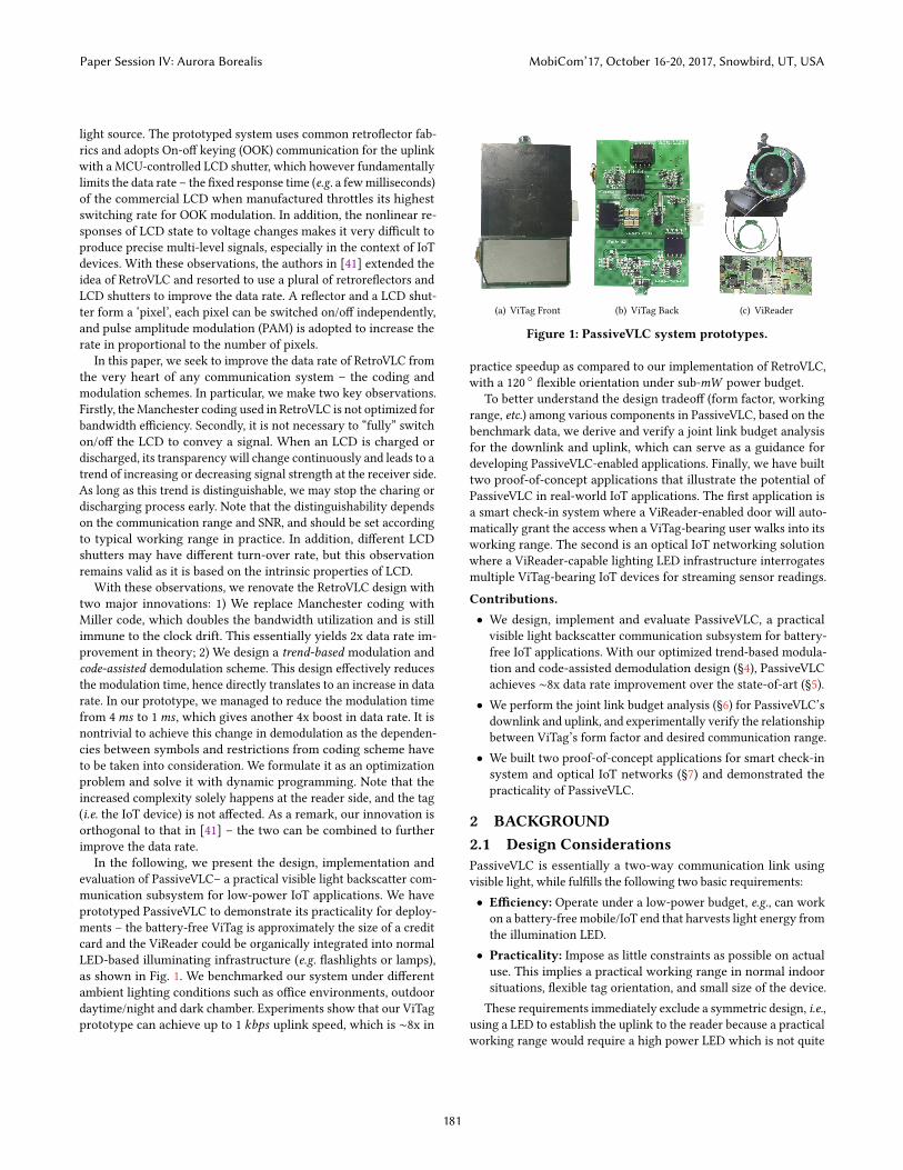
Solar panel
LCDShutter
Retroreflector
Photodiode
LED
Figure 3: RetroVLC/PassiveVLC design illustration.
the light to pass or be blocked by the polarizer film. We thus cantoggle the pass/block state of the whole LCD by imposing an electricfield (through the two surrounding glass electrodes) on the liquidcrystal layer. Note the liquid crystal molecules cannot instantlytoggle between twisted and untwisted state. It typically takes inthe range of few milliseconds, or termed as “response time”, whichfundamentally limits the data rate of OOK-based system [28].
3 SYSTEM DESIGNThe design of PassiveVLC overlaps with RetroVLC in its systemarchitecture (§3.1) and circuit implementation (§3.2), but optimizesthe software (de)modulation part of the retroreflecting link in termsof improving data rate (§4). In this section, we stay in the high levelto recap the key components of RetroVLC/PassiveVLC.
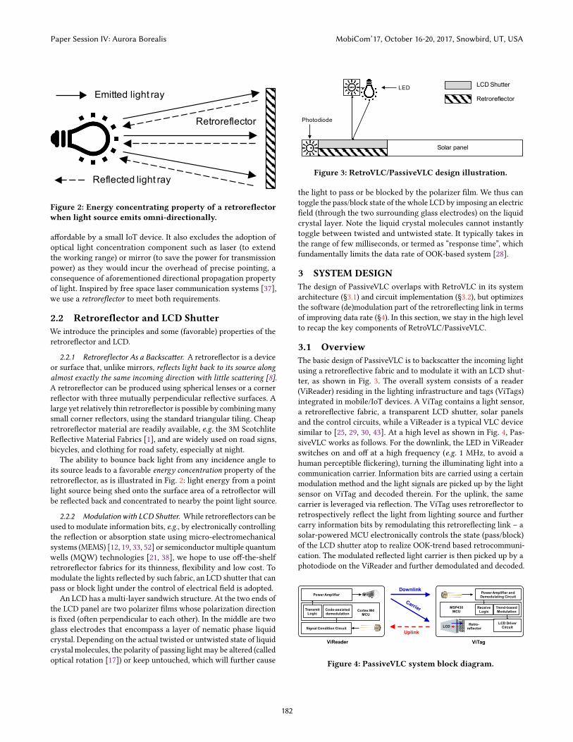
3.1 OverviewThe basic design of PassiveVLC is to backscatter the incoming lightusing a retroreflective fabric and to modulate it with an LCD shut-ter, as shown in Fig. 3. The overall system consists of a reader(ViReader) residing in the lighting infrastructure and tags (ViTags)integrated in mobile/IoT devices. A ViTag contains a light sensor,a retroreflective fabric, a transparent LCD shutter, solar panelsand the control circuits, while a ViReader is a typical VLC devicesimilar to [25, 29, 30, 43]. At a high level as shown in Fig. 4, Pas-siveVLC works as follows. For the downlink, the LED in ViReaderswitches on and off at a high frequency (e.g. 1 MHz, to avoid ahuman perceptible flickering), turning the illuminating light into acommunication carrier. Information bits are carried using a certainmodulation method and the light signals are picked up by the lightsensor on ViTag and decoded therein. For the uplink, the samecarrier is leveraged via reflection. The ViTag uses retroreflector toretrospectively reflect the light from lighting source and furthercarry information bits by remodulating this retroreflecting link – asolar-powered MCU electronically controls the state (pass/block)of the LCD shutter atop to realize OOK-trend based retrocommuni-cation. The modulated reflected light carrier is then picked up by aphotodiode on the ViReader and further demodulated and decoded.
Power Amplifier
Code-assisted demodulation
Signal Condition Circuit
Transmit Logic
Cortex M4 MCU
Power Amplifier and Demodulating Circuit
Trend-based Modulation
LCD Driver Circuit
Receive Logic
MSP430 MCU
Downlink
Uplink
ViReader ViTag
Retro-reflectorLCD
Figure 4: PassiveVLC system block diagram.
Paper Session IV: Aurora Borealis MobiCom’17, October 16-20, 2017, Snowbird, UT, USA
182
ViReader ViTag
Cortex M4 based MCU Power Amplifier
Preamplifier Tuned Amplifier
1MHz
Code-assisted Demodulator Encode and
Transmit Logic
Gain Control
ADC
Programmable-GainDifferential Amplifier
Baseband Amplifier
Precision RectifierDemodulator
Demodulator
Comparator
Voltage Boost Circuit
LCD
-+
MCU (MSP430)LCD Driver
Tuned Amplifier
Power Manager
Decoder
Transmit and
Encode Logic
Downlink
Uplink
717 1 4
2
35
16 1412 11 10 9
8
13
6
15 Differential Signal Wires
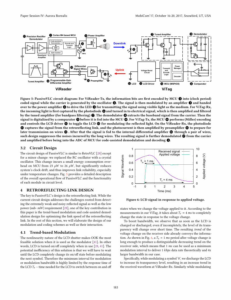
Figure 5: PassiveVLC circuit diagram: For ViReader-Tx, the information bits are first encoded by MCU 1 into (clock period)coded signal while the carrier is generated by the oscillator 2 . The signal is then modulated by an amplifier 3 and handedover to the power amplifier 4 to drive the LED 5 for transmitting the signal using visible light as the medium. For ViTag-Rx,the incoming light is first captured by the photodiode 6 and turned in to electrical signal, which is then amplified and filteredby the tuned amplifier (for bandpass filtering) 7 . The demodulator 8 extracts the baseband signal from the carrier. Then thesignal is digitalized by a comparator 9 before it is fed into the MCU 10 . For ViTag-Tx, the MCU 10 performs (Miller) encodingand controls the LCD driver 11 to toggle the LCD 12 for modulating the reflected light. On the ViReader-Rx, the photodiode 13 captures the signal from the retroreflecting link, and the photocurrent is then amplified by preamplifier 14 to prepare forlater transmission on wires 15 . After that the signal is fed to the internal differential amplifier 16 through a pair of wires,such design suppresses the noises incurred by the long wires. The resulting signal is further demodulated 17 from the carrierand amplified before being into the ADC of MCU for code-assisted demodulation and decoding 1 .
3.2 Circuit DesignThe circuit design of PassiveVLC is similar to RetroVLC [28] exceptfor a minor change: we replaced the RC oscillator with a crystaloscillator. This change incurs a small energy consumption over-head on MCU from 23 µW to 26 µW , but significantly reducessystem’s clock drift, and thus improves link reliability, especiallyunder temperature changes. Fig. 5 provides a detailed descriptionof the overall operational flow of PassiveVLC and the functionalityof each module in circuit level.
4 RETROREFLECTING LINK DESIGNThe key to PassiveVLC’s design is the retroreflecting link. While thecurrent circuit design addresses the challenges rooted from detect-ing the extremely weak and noisy reflected signal as well as the lowpower (sub-mW ) requirement [28], one of the key contribution inthis paper is the trend-based modulation and code-assisted demod-ulation design for optimizing the link speed of the retroreflectinglink. In the rest of this section, we will elaborate the design of ourmodulation and coding schemes as well as their interaction.
4.1 Trend-based ModulationThe nonlinearity nature of the LCD shutter makes OOK the mostfeasible solution when it is used as the modulator [41]. In otherwords, LCD is turned on/off completely when in use [28, 41]. Thepotential inefficiency of this solution is that we will have to waituntil the LCD completely change its on/off state before modulatingthe next symbol. Therefore the minimum interval for modulationor modulation bandwidth is highly limited by the response time ofthe LCDTr – time needed for the LCD to switch between on and off
0
0.2
0.4
0.6
0.8
1
-1 0 1 2 3 4 5 0
2
4
6
8
10
Ts = 1 ms
Tr = 4 ms
Sign
al W
avef
orm
Appl
ied
volta
ge (V
)
Time (ms)
Received signalApplied voltage
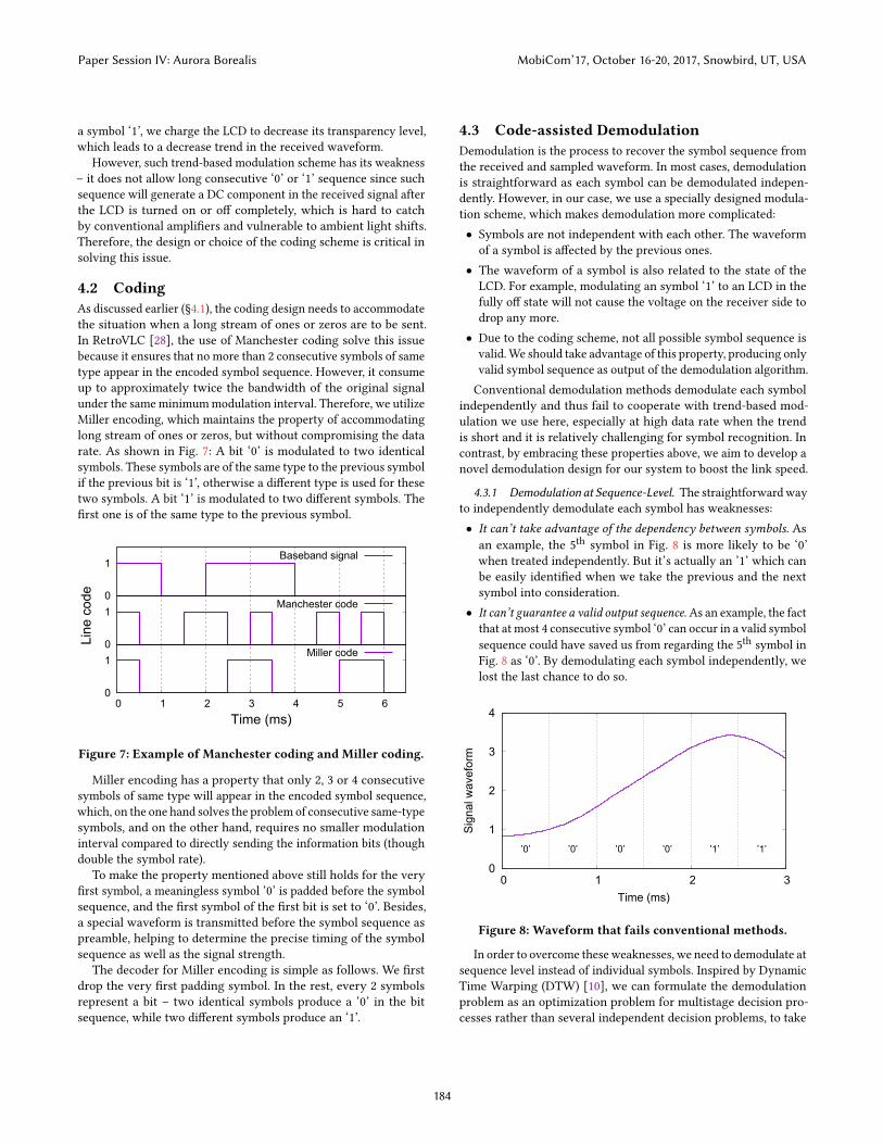
Figure 6: LCD signal in response to applied voltage.
states when we change the voltage applied to it. According to themeasurements in our ViTag, it takes aboutTr = 4ms to completelychange the state in response to the voltage change.
To boost bandwidth, we observe that as soon as the LCD ischarged or discharged, even if incompletely, the level of its trans-parency will change over short time. The resulting trend of thevoltage change on the receiver side already conveys the informa-tion. As shown in Fig. 6, a Ts = 1ms period after voltage change islong enough to produce a distinguishable decreasing trend on thereceiver side, which means that 1ms can be used as a minimummodulation interval to deliver 1 kbps data rate theoretically and 4xlarger bandwidth in our case.
Specifically, whilemodulating a symbol ‘0’, we discharge the LCDto increase its transparency level, resulting in an increase trend inthe received waveform at ViReader-Rx. Similarly while modulating
Paper Session IV: Aurora Borealis MobiCom’17, October 16-20, 2017, Snowbird, UT, USA
183
a symbol ‘1’, we charge the LCD to decrease its transparency level,which leads to a decrease trend in the received waveform.
However, such trend-based modulation scheme has its weakness– it does not allow long consecutive ‘0’ or ‘1’ sequence since suchsequence will generate a DC component in the received signal afterthe LCD is turned on or off completely, which is hard to catchby conventional amplifiers and vulnerable to ambient light shifts.Therefore, the design or choice of the coding scheme is critical insolving this issue.
4.2 CodingAs discussed earlier (§4.1), the coding design needs to accommodatethe situation when a long stream of ones or zeros are to be sent.In RetroVLC [28], the use of Manchester coding solve this issuebecause it ensures that no more than 2 consecutive symbols of sametype appear in the encoded symbol sequence. However, it consumeup to approximately twice the bandwidth of the original signalunder the sameminimummodulation interval. Therefore, we utilizeMiller encoding, which maintains the property of accommodatinglong stream of ones or zeros, but without compromising the datarate. As shown in Fig. 7: A bit ‘0’ is modulated to two identicalsymbols. These symbols are of the same type to the previous symbolif the previous bit is ‘1’, otherwise a different type is used for thesetwo symbols. A bit ‘1’ is modulated to two different symbols. Thefirst one is of the same type to the previous symbol.
0
1
Baseband signal
0
1
Manchester code
0
1
0 1 2 3 4 5 6
Line
cod
e
Time (ms)
Miller code
Figure 7: Example of Manchester coding and Miller coding.
Miller encoding has a property that only 2, 3 or 4 consecutivesymbols of same type will appear in the encoded symbol sequence,which, on the one hand solves the problem of consecutive same-typesymbols, and on the other hand, requires no smaller modulationinterval compared to directly sending the information bits (thoughdouble the symbol rate).
To make the property mentioned above still holds for the veryfirst symbol, a meaningless symbol ‘0’ is padded before the symbolsequence, and the first symbol of the first bit is set to ‘0’. Besides,a special waveform is transmitted before the symbol sequence aspreamble, helping to determine the precise timing of the symbolsequence as well as the signal strength.
The decoder for Miller encoding is simple as follows. We firstdrop the very first padding symbol. In the rest, every 2 symbolsrepresent a bit – two identical symbols produce a ‘0’ in the bitsequence, while two different symbols produce an ‘1’.
4.3 Code-assisted DemodulationDemodulation is the process to recover the symbol sequence fromthe received and sampled waveform. In most cases, demodulationis straightforward as each symbol can be demodulated indepen-dently. However, in our case, we use a specially designed modula-tion scheme, which makes demodulation more complicated:• Symbols are not independent with each other. The waveformof a symbol is affected by the previous ones.• The waveform of a symbol is also related to the state of theLCD. For example, modulating an symbol ‘1’ to an LCD in thefully off state will not cause the voltage on the receiver side todrop any more.• Due to the coding scheme, not all possible symbol sequence isvalid.We should take advantage of this property, producing onlyvalid symbol sequence as output of the demodulation algorithm.Conventional demodulation methods demodulate each symbol
independently and thus fail to cooperate with trend-based mod-ulation we use here, especially at high data rate when the trendis short and it is relatively challenging for symbol recognition. Incontrast, by embracing these properties above, we aim to develop anovel demodulation design for our system to boost the link speed.
4.3.1 Demodulation at Sequence-Level. The straightforwardwayto independently demodulate each symbol has weaknesses:• It can’t take advantage of the dependency between symbols. Asan example, the 5th symbol in Fig. 8 is more likely to be ‘0’when treated independently. But it’s actually an ’1’ which canbe easily identified when we take the previous and the nextsymbol into consideration.• It can’t guarantee a valid output sequence.As an example, the fact
that at most 4 consecutive symbol ‘0’ can occur in a valid symbolsequence could have saved us from regarding the 5th symbol inFig. 8 as ‘0’. By demodulating each symbol independently, welost the last chance to do so.
0
1
2
3
4
0 1 2 3
’0’ ’0’ ’0’ ’0’ ’1’ ’1’
Sign
al w
avef
orm
Time (ms)
Figure 8: Waveform that fails conventional methods.
In order to overcome theseweaknesses, we need to demodulate atsequence level instead of individual symbols. Inspired by DynamicTime Warping (DTW) [10], we can formulate the demodulationproblem as an optimization problem for multistage decision pro-cesses rather than several independent decision problems, to take
Paper Session IV: Aurora Borealis MobiCom’17, October 16-20, 2017, Snowbird, UT, USA
184

symbol dependencies into consideration as well as the restrictionsexerted by sequence validity.
Here, we demodulate by “optimally” (§4.3.2) decomposing thereceived waveform into segments where each segment representsconsecutive symbols of same type. According to the propertiesmentioned in §4.2, some restrictions apply: Each segment shouldconsists of 2, 3 or 4 symbols; Segment of 4 symbols can only occurafter even number of symbols in the symbol sequence. In addition,minor error in timing should be to tolerated in case of possibleclock skew and clock drift. That is, we should allow segments tooverlap or separate a little bit in our decomposition.
4.3.2 Optimality of Decomposition. In §4.3.1 we formulate thedemodulation problem as an optimization problem. But the defi-nition of optimality remains unclear. To define optimality, a quan-titative index for how likely that a decomposition is correct for acertain waveform is critical. Therefore we proposed Match Score.
The Match Score for a certain decomposition is defined as thesum of all its segments’ Match Score. The Match Score of a segmentis defined as the similarity of its waveform to the correspondingreference waveform.
But how to quantify the similarity of two given waveforms Xand Y, both of the length n? In some existing systems like CDMA,correlation coefficient corr(X,Y) is used. But this is not suitablefor us since we need to sum up the Match Score of segments, whilethe sum of correlation coefficients is meaningless, especially whensegments are of different length. Therefore, we decide to develop anew ‘addable’ index.
An intuitive idea is to use the following formula:
NaiveSim (X,Y) =n∑i=1
(X[i] − Y[i])2
However, this formula is not practical because: It does not takeinto account the fact that the amplitude and mean of the waveformmay vary from symbol to symbol. Therefore, the following formula,in which a scale factor a and an offset b are applied to adaptivelyadjust the amplitude and mean of the waveform, is used to addressthis problem. In other words, we normalize the two waveforms ina way that minimize the Match Score.
Sim (X,Y) = mina≥amin,b
NaiveSim(aX + b,Y)
= mina≥amin,b
n∑i=1
(aX[i] + b − Y[i])2
where amin denotes the minimum scale allowed to prevent thewaveform from degrading or flipping, which is a positive numberusually set proportionally to the scale we obtained from preamble.As we calculate, the minimum value of the formula can be obtainedwhen
a = max(n∑X[i]Y[i] −
∑X[i]
∑Y[i]
n∑X[i]2 − (
∑X[i])2
,amin
)b =
1n
(∑Y[i] −
∑aX[i]
)
Fig. 9 gives an example of how it works, whereX denotes a possi-ble waveform of consecutive symbol ‘1’, Y denotes the correspond-ing reference waveform, aX + b denotes the normalized waveformof X. In this case, a = 3.4240,b = −4.2567, Sim (X,Y) = 1.0786.
0
2
0 1 2 3 4 5 6
Sign
al w
avef
orm
Time (ms)
YX
aX+b
Figure 9: An example illustrating the effect of a and b.
Now we can formally define the Match Score of a segment asthe Sim value of its waveform and the corresponding referencewaveform. More specifically, let lsym be the waveform length of asingle symbol, nseg be the number of symbols in the segment,W bethe waveform of the segment, R(t ,nseg) be the reference waveformof nseg consecutive symbol of type t (t = 0, 1) , then theMatch Scoreof the segment being nseg consecutive symbols of type t is definedas:
MatchScore (W, t ,nseg) = Sim(W,R(t ,nseg))
Note that the LCD may reach a fully on/off state, producing alevel part (approximately) in the end of the waveform. These levelparts should not be taken account in the calculation of Match Score.
4.3.3 Problem Formalization. Now let’s formally define the opti-mization problem for demodulation. Let S be the received waveform,n be the number of symbols to demodulate, lsym be the waveformlength of a single symbol, err be the maximum timing error allowedin samples (which is usually set proportionally to lsym), Start bethe position where the symbol sequence start (which can be ob-tained by searching preamble), the optimization problem can beformulated as:
minpi ,si ,m
m−1∑i=0
MatchScore (S[pi . . .pi + si lsym − 1], i mod 2, si )
s. t. − err ≤ p0 − Start ≤ err
− err ≤ pi − pi−1 + si−1lsym ≤ err (1 ≤ i < m)
2 ≤ si ≤ 3(∑
j<isi is even
)2 ≤ si ≤ 4
(∑j<i
si is odd)
n =m−1∑i=0
si
wherem denotes the number of segments, si denotes the numberof symbols in the ith segment, pi denotes the very first sample ofthe ith segment.
Paper Session IV: Aurora Borealis MobiCom’17, October 16-20, 2017, Snowbird, UT, USA
185
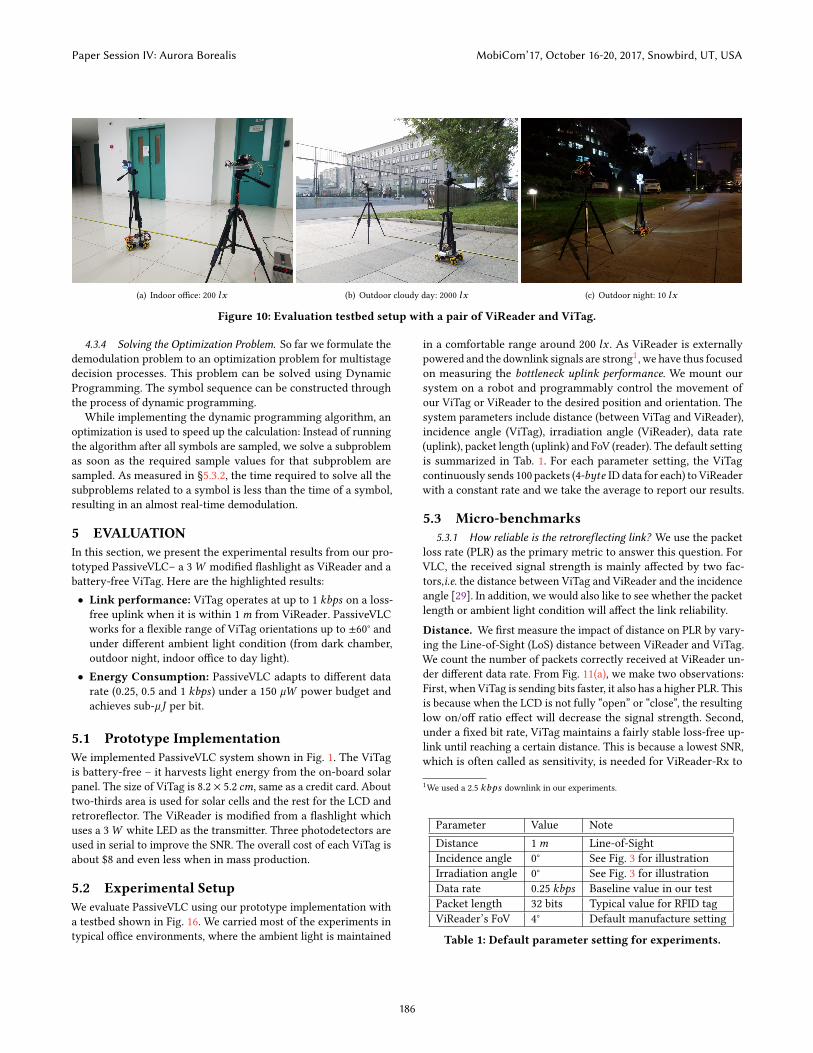
(a) Indoor office: 200 lx (b) Outdoor cloudy day: 2000 lx (c) Outdoor night: 10 lx
Figure 10: Evaluation testbed setup with a pair of ViReader and ViTag.
4.3.4 Solving the Optimization Problem. So far we formulate thedemodulation problem to an optimization problem for multistagedecision processes. This problem can be solved using DynamicProgramming. The symbol sequence can be constructed throughthe process of dynamic programming.
While implementing the dynamic programming algorithm, anoptimization is used to speed up the calculation: Instead of runningthe algorithm after all symbols are sampled, we solve a subproblemas soon as the required sample values for that subproblem aresampled. As measured in §5.3.2, the time required to solve all thesubproblems related to a symbol is less than the time of a symbol,resulting in an almost real-time demodulation.
5 EVALUATIONIn this section, we present the experimental results from our pro-totyped PassiveVLC– a 3W modified flashlight as ViReader and abattery-free ViTag. Here are the highlighted results:• Link performance: ViTag operates at up to 1 kbps on a loss-free uplink when it is within 1m from ViReader. PassiveVLCworks for a flexible range of ViTag orientations up to ±60° andunder different ambient light condition (from dark chamber,outdoor night, indoor office to day light).• Energy Consumption: PassiveVLC adapts to different datarate (0.25, 0.5 and 1 kbps) under a 150 µW power budget andachieves sub-µJ per bit.
5.1 Prototype ImplementationWe implemented PassiveVLC system shown in Fig. 1. The ViTagis battery-free – it harvests light energy from the on-board solarpanel. The size of ViTag is 8.2 × 5.2 cm, same as a credit card. Abouttwo-thirds area is used for solar cells and the rest for the LCD andretroreflector. The ViReader is modified from a flashlight whichuses a 3W white LED as the transmitter. Three photodetectors areused in serial to improve the SNR. The overall cost of each ViTag isabout $8 and even less when in mass production.
5.2 Experimental SetupWe evaluate PassiveVLC using our prototype implementation witha testbed shown in Fig. 16. We carried most of the experiments intypical office environments, where the ambient light is maintained
in a comfortable range around 200 lx . As ViReader is externallypowered and the downlink signals are strong1, we have thus focusedon measuring the bottleneck uplink performance. We mount oursystem on a robot and programmably control the movement ofour ViTag or ViReader to the desired position and orientation. Thesystem parameters include distance (between ViTag and ViReader),incidence angle (ViTag), irradiation angle (ViReader), data rate(uplink), packet length (uplink) and FoV (reader). The default settingis summarized in Tab. 1. For each parameter setting, the ViTagcontinuously sends 100 packets (4-byte ID data for each) to ViReaderwith a constant rate and we take the average to report our results.
5.3 Micro-benchmarks5.3.1 How reliable is the retroreflecting link? We use the packet
loss rate (PLR) as the primary metric to answer this question. ForVLC, the received signal strength is mainly affected by two fac-tors,i.e. the distance between ViTag and ViReader and the incidenceangle [29]. In addition, we would also like to see whether the packetlength or ambient light condition will affect the link reliability.
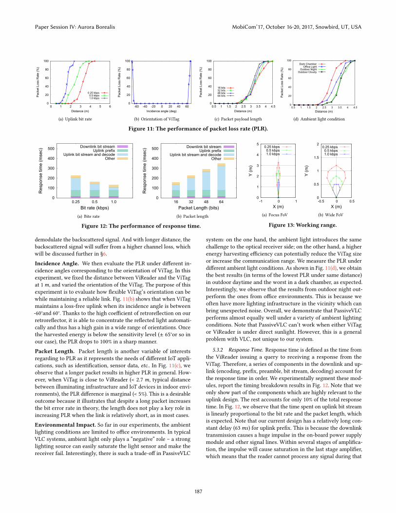
Distance. We first measure the impact of distance on PLR by vary-ing the Line-of-Sight (LoS) distance between ViReader and ViTag.We count the number of packets correctly received at ViReader un-der different data rate. From Fig. 11(a), we make two observations:First, when ViTag is sending bits faster, it also has a higher PLR. Thisis because when the LCD is not fully “open” or “close”, the resultinglow on/off ratio effect will decrease the signal strength. Second,under a fixed bit rate, ViTag maintains a fairly stable loss-free up-link until reaching a certain distance. This is because a lowest SNR,which is often called as sensitivity, is needed for ViReader-Rx to
1We used a 2.5 kbps downlink in our experiments.
Parameter Value NoteDistance 1m Line-of-SightIncidence angle 0° See Fig. 3 for illustrationIrradiation angle 0° See Fig. 3 for illustrationData rate 0.25 kbps Baseline value in our testPacket length 32 bits Typical value for RFID tagViReader’s FoV 4° Default manufacture setting
Table 1: Default parameter setting for experiments.
Paper Session IV: Aurora Borealis MobiCom’17, October 16-20, 2017, Snowbird, UT, USA
186
0
20
40
60
80
100
0 1 2 3 4 5 6
Pack
et L
oss
Rat
e (%
)
Distance (m)
0.25 kbps0.5 kbps1.0 kbps
(a) Uplink bit rate
0
20
40
60
80
100
-60 -40 -20 0 20 40 60
Pack
et L
oss
Rat
e (%
)
Incidence angle (deg)
(b) Orientation of ViTag
0
20
40
60
80
100
0.5 1 1.5 2 2.5 3 3.5 4 4.5
Pack
et L
oss
Rat
e (%
)
Distance (m)
16 bits32 bits48 bits64 bits
(c) Packet payload length
0
20
40
60
80
100
0.5 1 1.5 2 2.5 3 3.5 4 4.5
Pack
et L
oss
Rat
e (%
)
Distance (m)
Dark ChamberOffice Light
Outdoor NightOutdoor Cloudy
(d) Ambient light condition
Figure 11: The performance of packet loss rate (PLR).
0
100
200
300
400
500
0.25 0.5 1.0
Res
pons
e tim
e (m
sec)
Bit rate (kbps)
Downlink bit streamUplink prefix
Uplink bit stream and decodeOther
(a) Bite rate
0
100
200
300
400
500
16 32 48 64
Res
pons
e tim
e (m
sec)
Packet Length (bits)
Downlink bit streamUplink prefix
Uplink bit stream and decodeOther
(b) Packet length
Figure 12: The performance of response time.
0
1
2
3
4
5
-1 0 1
Y (m
)
X (m)
0.25 kbps0.5 kbps1.0 kbps
(a) Focus FoV
0
0.5
1
1.5
2
-0.5 0 0.5
Y (m
)
X (m)
0.25 kbps0.5 kbps1.0 kbps
(b) Wide FoV
Figure 13: Working range.
demodulate the backscattered signal. And with longer distance, thebackscattered signal will suffer from a higher channel loss, whichwill be discussed further in §6.
Incidence Angle. We then evaluate the PLR under different in-cidence angles corresponding to the orientation of ViTag. In thisexperiment, we fixed the distance between ViReader and the ViTagat 1m, and varied the orientation of the ViTag. The purpose of thisexperiment is to evaluate how flexible ViTag’s orientation can bewhile maintaining a reliable link. Fig. 11(b) shows that when ViTagmaintains a loss-free uplink when its incidence angle is between-60°and 60°. Thanks to the high coefficient of retroreflection on ourretroreflector, it is able to concentrate the reflected light automati-cally and thus has a high gain in a wide range of orientations. Oncethe harvested energy is below the sensitivity level (± 65°or so inour case), the PLR drops to 100% in a sharp manner.
Packet Length. Packet length is another variable of interestsregarding to PLR as it represents the needs of different IoT appli-cations, such as identification, sensor data, etc.. In Fig. 11(c), weobserve that a longer packet results in higher PLR in general. How-ever, when ViTag is close to ViReader (< 2.7 m, typical distancebetween illuminating infrastructure and IoT devices in indoor envi-ronments), the PLR difference is marginal (< 5%). This is a desirableoutcome because it illustrates that despite a long packet increasesthe bit error rate in theory, the length does not play a key role inincreasing PLR when the link is relatively short, as in most cases.
Environmental Impact. So far in our experiments, the ambientlighting conditions are limited to office environments. In typicalVLC systems, ambient light only plays a “negative” role – a stronglighting source can easily saturate the light sensor and make thereceiver fail. Interestingly, there is such a trade-off in PassiveVLC
system: on the one hand, the ambient light introduces the samechallenge to the optical receiver side; on the other hand, a higherenergy harvesting efficiency can potentially reduce the ViTag sizeor increase the communication range. We measure the PLR underdifferent ambient light conditions. As shown in Fig. 11(d), we obtainthe best results (in terms of the lowest PLR under same distance)in outdoor daytime and the worst in a dark chamber, as expected.Interestingly, we observe that the results from outdoor night out-perform the ones from office environments. This is because weoften have more lighting infrastructure in the vicinity which canbring unexpected noise. Overall, we demonstrate that PassiveVLCperforms almost equally well under a variety of ambient lightingconditions. Note that PassiveVLC can’t work when either ViTagor ViReader is under direct sunlight. However, this is a generalproblem with VLC, not unique to our system.
5.3.2 Response Time. Response time is defined as the time fromthe ViReader issuing a query to receiving a response from theViTag. Therefore, a series of components in the downlink and up-link (encoding, prefix, preamble, bit stream, decoding) account forthe response time in order. We experimentally segment these mod-ules, report the timing breakdown results in Fig. 12. Note that weonly show part of the components which are highly relevant to theuplink design. The rest accounts for only 10% of the total responsetime. In Fig. 12, we observe that the time spent on uplink bit streamis linearly proportional to the bit rate and the packet length, whichis expected. Note that our current design has a relatively long con-stant delay (63ms) for uplink prefix. This is because the downlinktransmission causes a huge impulse in the on-board power supplymodule and other signal lines. Within several stages of amplifica-tion, the impulse will cause saturation in the last stage amplifier,which means that the reader cannot process any signal during that
Paper Session IV: Aurora Borealis MobiCom’17, October 16-20, 2017, Snowbird, UT, USA
187

time. As a result, we add a fixed pattern of prefix before the uplinkpayload. The prefix also serves as the timing initialization in thedecode process. We plan to improve our hardware design to reduceits impact in the future. Finally, we acknowledge that the currentdesign of PassiveVLC is not very efficient in terms of response time– the ViReader can only issue at most 10 queries per second at thehighest rate (1 kbps) we achieved. We have a dedicated discussionon that in §8.
5.3.3 Working Range. Another important question to ask is:how far the ViTag can be away from the ViReader while still main-tain an acceptable data link. Here we define the working range asthe area within which the ViTag can harvest enough energy andtalk with the ViReader with a chance above 50%, i.e., PLR is lessthan 50%, and measure the working range in office environments.Specifically, in this experiment we also adjust the FoV of the flash-light to its maximum (35°) therefore it is expected to work in a widerbut shorter range. The working range in Fig. 13 is the area withinthe closed curve. First, we observe that a lower data rate link leadsto a larger working distance in terms of both depth and breadth,and the reason is similar as discussed in §5.3.1. With an uprightorientation of the ViTag, the maximum working distance is up to3.3m. Second, the angle of the working range is roughly equal tothe FoV of the lighting source. This is to be expected and in fact isa favorable feature because based on it we can predict and controlthe “width” of the working range. We note that PassiveVLC’s work-ing range can be further extended with more energy harvested. Aemulation-based analysis is provided in §6.
5.4 Energy ConsumptionMeasuring the energy consumption is always critical for under-standing the design trade-off (data rate, form factor, etc. in ourstudy) and finding optimization opportunities. In this experiment,we disconnect the solar panel from our tag and use Monsoon [5] tomeasure its power consumption. We power ViTag at 2 V becauseit’s the minimum and safe operating voltage for the on-board MCUto work. We operate the PassiveVLC as usual and shows the time-series power consumption snapshot on the ViTag in Fig. 14. Wecan see that in each query, ViTag spends 23ms in listening, whichaccounts for 678 µW and 15.6 µJ in total. This part of the energy ismostly spent on the static current of the analog circuit for signaldetection. In other words, the receiving circuit is always on becauseViTag never knows when it is expecting an incoming signal. Wecan address this deficiency with an efficient MAC protocol design.Then the ViTag receives the downlink bit stream and encodes thecontent to response, which consumes 373 µW . After that it turnsoff the receiving circuit and starts to transmit. In the transmissionstage, ViTag spends less than 117 µW on average at the highest bitrate, which is much lower thanmW -level LED-based transmission.We also see that ViTag spent more power in transmission but lessenergy per bit when it operates at a higher bit rate.
Overall, we demonstrate that with such a low energy budget, weare able to drive it by harvesting light energy using only small solarcells (amore detailed analysis is provided in §5.5).We summarize thebreak-down power/energy consumption for each query in Tab. 2.
0
0.5
1
1.5
2
2.5
1.4 1.5 1.6
ListeningReceiving and encoding
Transmitting
Charging capacitors in Rx circuit
Pow
er (m
W)
Time (s)
Figure 14: Snapshot of power consumption on ViTag.
ComponentBit rate 0.25 kbps 0.5 kbps 1.0 kbps
Backscattering state 95 µW 108 µW 117 µWReceiving state 373 µW 398 µW 408 µWAverage power 97 µW 113 µW 152 µWEnergy per bit 0.38 µJ 0.22 µJ 0.12 µJ
Table 2: Energy consumption of ViTag per query.
5.5 Size TradeoffIn our ViTag implementation, we dedicate two-thirds of the area tosolar cell and one-third to retroreflector. It is natural to ask: is thisratio the right choice or even the golden rule?
From Tab. 2, we observe that in the process of a query, peakpower happens in the receiving state. In addition, the passive na-ture of PassiveVLC determines that the receiving phase is aheadof the backscattering phase, which results in a more challengingrequirement for energy harvesting. For instance, in the case of0.25 kbps , the power provided by solar panel needs to meet the re-quirement of the peak power (373 µW ) instead of the (much lower)average power (97 µW ).
Our measurements show that in the dark chamber, the LEDflashlight casts 240 lux at the solar panel from a distance of 5maway. In turn, one single solar cell (at the size of 54 × 27mm) is ableto provide 196 µW at 1.98 V . Therefore, the two cells we use areable to provide 392 µW to cover the required energy consumption.Note that this energy harvesting measurement is conservative –the ambient light intensity is often larger than 200 lux and thusmore energy can be harvested for powering ViTag. To this end, ourexperimental measurements justify the ratio in our prototype.
Furthermore, the aforementioned scenario assumes a continuouscommunication is required. If the communication process can beintermittent, then the power requirements can be relaxed becausein practice it just takes the solar panel more time to harvest theenergy to reach the operating voltage.
6 LINK BUDGET ANALYSISMuch like the link budget analysis on RF links [7], it is desirableto perform similar analysis for PassiveVLC to understand the re-lationship and trade-off among the involved key factors such asdevice’s form-factor size, transmitted power of the illuminatinginfrastructure and the communication distance. For instance, when
Paper Session IV: Aurora Borealis MobiCom’17, October 16-20, 2017, Snowbird, UT, USA
188

Symbol ParameterPt Transmission power of the light sourceGt Directional gain of the light sourceGr e Directional gain of the retroreflectorLm Loss through LCD modulatorAr e Projected area of retroreflectorAr Projected area of photodiode in ViReader-RxR Communication distanceθ Irradiation angle, see Fig. 15 for illustrationα Observation angle, see Fig. 15 for illustrationβ Incidence angle, see Fig. 15 for illustration
Table 3: Parameters in link budget analysis.
our ViReader is integrated into car’s headlight for the purpose ofrecognizing road sign or pedestrian at least 30 m away, what’sthe required minimum size of ViTag? As another example, whena ViReader-enabled ceiling light wants to talk to the IoT devicesplaced in indoor environments, what is the suggested transmissionpower of the lighting infrastructure? Intuitively, a small increase inrange will lead to a significant increase in path loss. To compensatefor that, one simple solution is to adopt a larger retroreflector-LCDsuite to concentrate more energy for the uplink budget. However,a larger LCD comes with more energy consumption, and in turnneeds a larger solar panel. Hence, a systematic analysis wouldprovide insights for guiding real application deployment.
For a retroreflector-based visible light backscatter communica-tion system with LCD modulators, we propose a model (with allthe parameter definition in Tab. 3) to count in the transmissionpower of the light source and all the factors of the gains and lossesfrom the transmitter and the visible channel medium (downlink,retroreflector, LCD, etc.). The energy received by the photodiodesof ViReader is as follows:
Pr = PtGtAr e4πR2
Gr eLmAr4πR2
In this equation, there are six factors contributing to the twocritical phases which we will elaborate in the rest of this section.
6.1 Power budget of Passive/Retro TransmitterThe transmission power of the uplink actually originates fromViReader-Tx. The radiated on-path light energy is determined byPt andGt (θ ) (transmission power and directional characteristics ofthe light source) often modeled by Lambertian model [9]. In otherwords, these two factors together indicate how strong the downlinklight beam is emitted towards the ViTag.
The third factor characterizes the downlink path loss and howmuch energy can be collected by the retroreflector of area Ar e ata distance of R from ViReader-Tx, which is similar to Friis freespace equation in radio propagation. In our case, thanks to itsenergy concentration property (Fig. 2), a larger retroreflector canharvest more energy for backscattering and thus improve the SNRof the received signal and potentially increase the communicationdistance. However, we note that it is not always practical to replyon increasing the retroreflector’s area to extend the distance. Thelinearity can be easily overwhelmed by the square factor in power
attenuation, let alone the attenuation factor becomes quadraticwhen considering the uplink together.
6.2 Path Loss of RetrocommunicationThe first three factors compute the amount of energy captured byViTag. The next step is to determine how much the backscatteredenergy can reach at the photodiodes or light sensor in ViReader-Rx.
Typical omni-directional antenna has relatively low directionalgain because the energy disperses in all directions. However, thanksto the auto-focus feature of retroreflectors, it is possible to meetboth high gain and wide angular range at the same time. Gr e ,the directional gain of the retroreflector, plays a key role here.To be more specific, Gr e is equal to RA (α , β ), the retroreflectioncoefficient of the material, which determines how much energy itcan concentrate for retroreflection given the incident light beam ata certain incidence angle β , to a certain observation angle (towardsto the light sensor) α , deviated from the incident light. 2 Whileα is determined by the communication distance once the relativeposition of led and photodiode is fixed, β is directly associatedwith how flexible the orientation of ViTag can be when point toViReader. For visible light backscatter systems, it is desired to havesuch material with a high RA and it is insensitive to β at the sametime. For the commodity retroreflectors [1] we use, it has an RAof 500 cd · lx−1·m−2 (β = 5 ◦,α = 0.2 ◦), which leads to a Gr e of27 dBi . In addition, RA only attenuates 5 dB as β reaches to 40 ◦.Our evaluation shows that at β = 60 ◦, the gain is still sufficient tosupport an uplink transmission in 1 m. On the other hand, whenβ is fixed, RA stays high only within a small α (typically less than1 ◦) and attenuates sharply as α rises above 1.5 ◦. In Fig. 15, weshow the illustration of the energy distribution of the reflected ingray scale. The resulting concentrated and narrow reflected beamsuggested the placement of the light sensor is crucial in improvingthe SNR of the uplink.
Lm , the energy loss when light passes through the LCD modula-tor, also impacts the backscattered signal strength. In our system,the incidence light will pass through the LCD twice, before andafter the retroreflection. Due to the polarizing nature of the LCD[2], a beam of non-polarized light becomes polarized after pass-ing through and lost 50% power. Coupled with other factors (such
2An illustration of these angles can be found in Fig. 15.
Figure 15: Reflected energy concentrates in a narrow obser-vation angle of about 1.5 ◦.
Paper Session IV: Aurora Borealis MobiCom’17, October 16-20, 2017, Snowbird, UT, USA
189

0
0.2
0.4
0.6
0.8
1
2 4 6 8 10 12 14
Nor
mal
ized
refle
cted
ene
rgy
Area (cm2)
Measurementy = 0.083x - 0.174
(a) Area of retroreflector
10-3
10-2
10-1
1
2 3 4 5
Nor
mal
ized
refle
cted
ene
rgy
Distance (meter)
Measurementy = 2.043x-4.616
(b) Communication distance
Figure 16: Model fitting for link budget analysis.
as absorption of liquid crystal), our measurements show that thepower loss for the first time passing through the LCD is approxi-mately 65%. The case of the second time is much more complicatedbecause the retroreflector may change the polarization directionof the light, and it is challenging to measure the loss because theincident and outgoing light beams overlap in space. We estimatethis loss as 50%3 and thus Lm is approximately -7.6 dB. In addition,Lm also is also relevant to the data rate because when the LCD(dis)charging time is reduced, the amplitude of the modulated signalis “attenuated”as well. In our measurements, compared with thecase of 0.25 kbps , the extra loss at a rate of 0.5 kbps and 1.0 kbpsis 7.7 dB and 20.4 dB respectively. Note that this measurement isbased on our ViReader-Rx module, and thus it includes the impactof the variant frequency response in our circuit implementationwhen ViTag operates at different data rate.
We have conducted several controlled experiments to verify ouranalysis. First, we change the area of retroreflector Ar e and fixother parameters. The results shown in Fig. 16(a) demonstrate thatreceived signal strength (square of the ADC voltage reading) islinearly proportional to Ar e with R2 of 0.9886. Next, we fix Ar eand change the communication distance R and plot the resultsin Fig. 16(b). We make a linear fit of the received signal strengthand the distance in log scale. The results show that the receivedsignal strength is inversely proportional to 4.6th power of the dis-tance, which fits our model well with R2 of 0.9953. Note that ourmeasurement starts at 1.2m because the ADC is saturated froma closer location. However, PassiveVLC can still work at the dis-tance of [0.6,1.2]m as long as we operate the average voltage whentrend-based modulation is applied away from the saturation region.
7 PROOF-OF-CONCEPT APPLICATIONSWe evaluate two proof-of-concept applications to show how Pas-siveVLC applies to real world scenarios.
7.1 Smart Check-in SystemMost existing smart check-in systems use RFID card, fingerprint oriris based identification techniques which requires a user in prox-imity. We argue that when bearing with ViTag a badge, PassiveVLCusers can potentially enjoy a seamless experience when passingby different check-in points – a ViReader-enabled door will auto-matically grant the access when a authenticated PassiveVLC useris heading up into its working range, e.g., from 2m away. Thanks3When the linearly polarized light is reflected by the retroreflector, the orientation ofthe polarized light is evenly distributed in all directions. Therefore the polarizer willdecrease the reflected light intensity by about 50%.
to the directionality of light, PassiveVLC can mitigate the falsepositives in RFID’s case.
To evaluate the usability of PassiveVLC system in such scenario,we mount our ViReader prototype on the ceiling at 2m in frontof a door with a dip angle of 40 ◦ to ensure a 0.5 m of workingrange on the floor derived from the analysis of ground projectionof the light cone. The number of 0.5m is chosen to account for bothPassiveVLC’s response time (225ms) and human walking speed (1m/s). We ask five male and female subjects to wear our ViTag badgeat different height (1, 1.05, 1.1, 1.15, 1.2m) and head up towards thedoor at their natural walking speed. We count a test “successful” asViReader is able to receive the ViTag’s response without issuingretries. We conduct 100 tests in total and our experimental resultsshow PassiveVLC achieve 90% of success rate.
7.2 Optical IoT/Sensor NetworkingThe second use case we present is optical IoT/sensor networking.Home/office sensors (motion, temperature, humidity et al.) can beintegrated into ViTag and their sensory readings can be streamed toa ViReader-capable lighting LED infrastructure. PassiveVLC bringstwo benefits in this scenario: Firstly, it reduces the deploymentcost because of its battery-free property. Secondly, it avoids theinterference with other existing RF-based devices.
We instrument a wide FoV ceiling lamp of with our ViReaderand place 1 to 5 ViTags in different locations (table, chair, TV, etc.)but still within ViReader’s view. Each ViTag is assigned a unique IDand will response to ViReader’s ID-based interrogation with 4-bytesensor data. The time to finish polling all the present ViTags are0.225, 0.45, 0.675, 0.9 and 1.125 sec when 1 to 5 ViTags deployedrespectively.We observe this “perfect” linearity because PassiveVLCis not running any operating system and thus all the operationscan be scheduled into cycles precisely. We note that a completePassiveVLC polling system requires a scanning/initialization phaseas well as a MAC protocol, which we leave for future work.
8 DISCUSSION
Non-Line-of-Sight (NLoS). Due to the directional propagationproperty of light, PassiveVLC gains certain intrinsic security benefitsuch as sniff-proof, but it also suffers from an intrinsic limitation -it cannot work in NLoS situations, as any VLC system does.
DataRate. The data rate or response time of PassiveVLC is doomedby the LCD shutter’s turn-over rate, which may further limit its ap-plication to those low data rate IoT applications. There are severalhandy ways to improve the data rate to some extent. For exam-ple, instead of using a black-white LCD, color LCDs can be usedto enable more communication channels. Accordingly, color fil-ters should be added on the receiver side to distinguish differentchannels. As another example, one can use a plural of retroflectorsand LCD shutters to achieve almost linearly increasing data rate,as evidenced in [41]. We further believe, once the technology iswidely adopted, the market demand will stimulate the productionof faster LCD shutters. Finally, devices other than LCD, e.g., digitalmicromirror device (DMD) can be treated as a promising modulatorcandidate – it can achieve tens of kbps with 100mW power budget
Paper Session IV: Aurora Borealis MobiCom’17, October 16-20, 2017, Snowbird, UT, USA
190

[3], and it can be useful for IoT device with a larger surface, suchas road sign, cloth fabrics etc.
Networked Operation. We have primarily focused on the com-munication aspects of a single ViTag-ViReader pair. When manyof these devices (both ViTag and ViReader) are in range of eachother, we need mechanisms to arbitrate the channel access. We havedesigned a simple query-response MAC similar to that of RFID andapplied in the second proof-of-concept application. Unlike RFIDwhich is completely passive, the solar panel can continuously har-vest light energy from ambient light, it may initiate a communi-cation session to the reader. Thus, the MAC needs to be slightlymodified to accommodate this new situation. We have omitted thispart for sake of space constraint.
9 RELATEDWORKPassiveVLC is inspired by the idea of (radio) backscatter communi-cation but differ from that by using visible light as the medium toachieve low power communication.
Visible Light Communication Systems. There have been manyefforts exploring communication mediums wherein visible lightscarry information. Most works, however, either deal with only one-way communication without an uplink [14, 24, 26, 45], or go in atwo-way fashion with both sides supplied by battery [13, 16, 27],which limit the practicality for real-world deployment. Specifically,LED-to-phone systems [25, 29, 39] only support downlink transmis-sions, targeted at phone localization. LED-to-LED systems [40, 47]consider visible light networks, where each end is not meant to bemobile, and is not battery-free. Until recently, the idea of visiblelight passive communication has been introduced and exercisedin [28, 41, 48]. Specifically, by using the incoming light from theexisting indoor lighting infrastructure as the carrier, RetroVLC [28]uses the retroreflector fabric to backscatter the encoded informa-tion modulated by a LCD shutter and achieve 0.125 kbps usingOOK modulation and Manchester coding4. PassiveVLC is built onthe RetroVLC framework but achieves 1 kbps (8x over RetroVLC)using the same LCD shutter based on an optimized trend-basedmodulation and code-assisted demodulation design. The authorsin [41] extends this idea by proposing a pixelated VLC backscatter,which uses multiple smaller reflectors and LCD shutters to formnumbers of pixels and improves the link throughput proportion-ally from 200 bps to 600 bps by using three pixels. However, onepotential limitation is that it only works when the communica-tion distance is fixed. On the other hand, instead of modulatinglight sources, the author in [48] embed data as various grayscaleseamless patterns into reflective surface objects. An optical receivercan leverage its relative mobility to the object to scan the time se-ries of the photodiode sensor reading of the reflected optical pulsefrom the unmodulated ambient light signals to realize mobile datacommunication. PassiveVLC, by contrast, is able to dynamicallychanges the data to send on the reflecting link and thus is moresuitable for IoT applications.
4This result is carried out by implementing RetroVLC on the same hardware as Pas-siveVLC. The LCD used in RetroVLC [28] has a significantly shorter response timeand thus achieves 0.5 kbps .
Radio Backscatter Communication Systems. Backscatteringis a way to provide transmission capability for extremely low-powerdevices, substituting the need for devices actively generating signals.The technique has been primarily used by RFID tags [20, 44]. Re-cently, TV-based [31, 36] and Wi-Fi [11, 22, 23, 49] systems startedemploying and advancing this technique. Our system shares thesame design principles – achieve low energy communication by es-tablishing a backscatter link. Although the current implementationof PassiveVLC is inferior to most radio backscatter system in termsof transmission rate (1 kbps versus several kbps [18, 22, 31, 46, 50]and even orders of Mbps [11, 23, 36, 49]) by a few orders of mag-nitude, our work has several advantages over RF-based approachin general: First, PassiveVLC is based on visible light, and thuscompletely immune to the interference from RF spectrum which isalready crowded with “default” LAN and PAN technologies suchas WiFi, BLE. Second, because of the backscattering nature, theseRF-based systems tend to expose their transmissions to a wide sur-rounding area, leaving a good chance for side readers to overhearthe information being transmitted. In contrast, ViTag relies on VLC,which implies that eavesdroppers are easily discernible. The useof retroreflectors further constraints the uplink transmission tostick along the tag-reader path. As a result, PassiveVLC comes witha good security property inherently, while other systems have toenhance their security with extra efforts [34, 51].
10 CONCLUSIONThis paper present a first comprehensive attempt to the design,implementation, evaluation, demonstration and understanding ofa practical backscattering communication system exploiting thevisible light medium. With the proposed trend-based modulationand code-assisted demodulation design, we built a battery-freevisible light backscatter tag and achieved up to 1 kbps uplink datarate, using commercially off-the-shelf retroreflector fabric and LCDshutter. While this technology is still in its infant stage, we believethis paper sheds light on new ways of thinking machine to machinecommunication in those scenarios where battery-free, sniff-proof,biologically friendly and spectral efficiency are much desired.
ACKNOWLEDGMENTSWe are grateful to the MobiCom reviewers for their constructivecritique, and our shepherd, Dr. Yingying Chen in particular, forher valuable comments, all of which have helped us greatly im-prove this paper. We also thank Pan Hu, Liqun Li, Chao Sun, XinyuZhang, Chunshui Zhao and Lin Zhong for their thoughtful inputand suggestions based on an early version of the work. This work issupported in part by National Key Research and Development Plan,China (Grant No. 2016YFB1001200), Science and Technology Inno-vation Project of Foshan City, China (Grant No. 2015IT100095) andScience and Technology Planning Project of Guangdong Province,China (Grant No. 2016B010108002).
Paper Session IV: Aurora Borealis MobiCom’17, October 16-20, 2017, Snowbird, UT, USA
191

REFERENCES[1] [n. d.]. 3M Scotchlite 8906 Silver Fabric Trim. http://solutions.3m.com/wps/
portal/3M/en_US/ScotchliteNA/Scotchlite/Products/~/8906-Silver-Fabric-Trim.([n. d.]).
[2] [n. d.]. Basic Working Principle of LCD Panel. http://qxwujoey.tripod.com/lcd.htm. ([n. d.]).
[3] [n. d.]. DLP7000DLP®0.7 XGA 2x LVDS Type A DMD. http://www.ti.com/lit/ds/symlink/dlp7000.pdf. ([n. d.]).
[4] [n. d.]. Mobike. http://mobike.com/. ([n. d.]).[5] [n. d.]. Monsoon power monitor. http://www.msoon.com/LabEquipment/
PowerMonitor. ([n. d.]).[6] Yuvraj Agarwal, Bharathan Balaji, Seemanta Dutta, Rajesh K Gupta, and Thomas
Weng. 2011. Duty-cycling buildings aggressively: The next frontier in HVACcontrol. In Proc. ACM/IEEE IPSN.
[7] Alejandro Aragon-Zavala. 2008. Antennas and propagation for wireless communi-cation systems. John Wiley & Sons.
[8] Harrison H Barrett and Stephen F Jacobs. 1979. Retroreflective arrays as approxi-mate phase conjugators. Optics letters 4, 6 (1979).
[9] Ronen Basri and David W Jacobs. 2003. Lambertian reflectance and linear sub-spaces. IEEE transactions on pattern analysis and machine intelligence 25, 2 (2003).
[10] Donald J Berndt and James Clifford. 1994. Using dynamic time warping to findpatterns in time series.. In Proc. ACM KDD workshop, Vol. 10.
[11] Dinesh Bharadia, Kiran Raj Joshi, Manikanta Kotaru, and Sachin Katti. 2015.Backfi: High throughput wifi backscatter. In Proc. ACM SIGCOMM.
[12] Trevor K Chan and Joseph E Ford. 2006. Retroreflecting optical modulator usingan MEMS deformable micromirror array. IEEE Journal of lightwave technology24, 1 (2006).
[13] CW Chow, CH Yeh, YF Liu, and Y Liu. 2011. Improved modulation speed ofLED visible light communication system integrated to main electricity network.Electronics letters 47, 15 (2011).
[14] Kaiyun Cui, Gang Chen, Zhengyuan Xu, and Richard D Roberts. 2010. Line-of-sight visible light communication system design and demonstration. In Proc. IEEECSNDSP.
[15] Biyi Fang, Nicholas D Lane, Mi Zhang, Aidan Boran, and Fahim Kawsar. 2016.BodyScan: Enabling radio-based sensing on wearable devices for contactlessactivity and vital sign monitoring. In Proc. ACM MobiSys.
[16] D. Giustiniano, N. O. Tippenhauer, and S. Mangold. 2012. Low-complexity visiblelight networking with led-to-led communication. In IFIP Wireless Days.
[17] John Frederick William Herschel. 1820. On the Rotation Impressed by Plates ofRock Crystal on the Planes of Polarization of the Rays of Light, as Connectedwith Certain Peculiarities in Its Crystallization. Transactions of the CambridgePhilosophical Society 1 (1820).
[18] Pan Hu, Pengyu Zhang, and Deepak Ganesan. 2015. Laissez-faire: Fully asym-metric backscatter communication. In Proc. ACM SIGCOMM.
[19] Colin Jenkins, J Gordon Brown, Lijie Li, Walter Johnstone, and Deepak Uttam-chandani. 2007. MEMS retro-phase-modulator for free-space coherent opticalcommunications. IEEE Journal of Selected Topics in Quantum Electronics 13, 2(2007).
[20] S Jeon, Y Yu, and J Choi. 2006. Dual-band slot-coupled dipole antenna for 900MHz and 2.45 GHz RFID tag application. Electronics letters 42, 22 (2006).
[21] Stephane Junique, Daniel Agren, QinWang, Susanne Almqvist, Bertrand Noharet,and Jan Y Andersson. 2006. A modulating retro-reflector for free-space opticalcommunication. IEEE photonics technology letters 18, 1 (2006).
[22] Bryce Kellogg, Aaron Parks, Shyamnath Gollakota, Joshua R Smith, and DavidWetherall. 2015. Wi-fi backscatter: internet connectivity for RF-powered devices.In Proc. ACM SIGCOMM.
[23] Bryce Kellogg, Vamsi Talla, Shyamnath Gollakota, and Joshua R Smith. 2016.Passive Wi-Fi: bringing low power to Wi-Fi transmissions. In Proc. USENIX NSDI.
[24] Toshihiko Komine and Masao Nakagawa. 2003. Integrated system of white LEDvisible-light communication and power-line communication. IEEE Transactionson Consumer Electronics 49, 1 (2003).
[25] Ye-Sheng Kuo, Pat Pannuto, Ko-Jen Hsiao, and Prabal Dutta. 2014. Luxapose:Indoor positioning with mobile phones and visible light. In Proc. ACM MobiCom.
[26] Hoa Le Minh, Dominic O’Brien, Grahame Faulkner, Lubin Zeng, Kyungwoo Lee,Daekwang Jung, YunJe Oh, and Eun Tae Won. 2009. 100-Mb/s NRZ visible lightcommunications using a postequalized white LED. IEEE Photonics TechnologyLetters 21, 15 (2009).
[27] Hongdi Li, Yaqiang Liu, Tao Xing, Yu Wang, Jorge Uribe, Hossain Baghaei, Shup-ing Xie, Soonseok Kim, Rocio Ramirez, and Wai-Hoi Wong. 2003. An instan-taneous photomultiplier gain calibration method for PET or gamma cameradetectors using an LED network. In IEEE Nuclear Science Symposium Conference
Record.[28] Jiangtao Li, Angli Liu, Guobin Shen, Liqun Li, Chao Sun, and Feng Zhao. 2015.
Retro-VLC: Enabling battery-free duplex visible light communication for mobileand iot applications. In Proc. ACM HotMobile.
[29] Liqun Li, Pan Hu, Chunyi Peng, Guobin Shen, and Feng Zhao. 2014. Epsilon: Avisible light based positioning system. In Proc. USENIX NSDI.
[30] Tianxing Li, Chuankai An, Zhao Tian, Andrew T Campbell, and Xia Zhou. 2015.Human sensing using visible light communication. In Proc. ACM MobiCom.
[31] Vincent Liu, Aaron Parks, Vamsi Talla, Shyamnath Gollakota, David Wetherall,and Joshua R Smith. 2013. Ambient backscatter: wireless communication out ofthin air. In Proc. ACM SIGCOMM.
[32] Jiakang Lu, Tamim Sookoor, Vijay Srinivasan, Ge Gao, Brian Holben, JohnStankovic, Eric Field, and Kamin Whitehouse. 2010. The smart thermostat:using occupancy sensors to save energy in homes. In Proc. ACM SenSys.
[33] Changping Luo and KW Goossen. 2004. Optical microelectromechanical systemarray for free-space retrocommunication. IEEE Photonics Technology Letters 16, 9(2004).
[34] Rajalakshmi Nandakumar, Krishna Kant Chintalapudi, Venkat Padmanabhan,and Ramarathnam Venkatesan. 2013. Dhwani: secure peer-to-peer acoustic NFC.In Proc. ACM SIGCOMM.
[35] Anh Nguyen, Raghda Alqurashi, Zohreh Raghebi, Farnoush Banaei-kashani,Ann C Halbower, and Tam Vu. 2016. A Lightweight And Inexpensive In-earSensing System For Automatic Whole-night Sleep Stage Monitoring. In Proc.ACM SenSys.
[36] Aaron N Parks, Angli Liu, Shyamnath Gollakota, and Joshua R Smith. 2014.Turbocharging ambient backscatter communication. In Proc. ACM SIGCOMM.
[37] G Goetz Peter, S Rabinovich William, Rita Mahon, L Murphy James, S FerraroMike, R Suite Michele, R Smith Walter, B Xu Ben, R Burris Harris, I MooreChristopher, et al. 2010. Modulating retro-reflector lasercom systems at the NavalResearch Laboratory. In Proc. IEEE Milcom.
[38] William S Rabinovich, R Mahon, PG Goetz, E Waluschka, DS Katzer, SC Binari,and GC Gilbreath. 2003. A cat’s eye multiple quantum-well modulating retro-reflector. IEEE Photonics Technology Letters 15, 3 (2003).
[39] Niranjini Rajagopal, Patrick Lazik, and Anthony Rowe. 2014. Visual light land-marks for mobile devices. In Proc. ACM/IEEE IPSN.
[40] Stefan Schmid, Giorgio Corbellini, Stefan Mangold, and Thomas R Gross. 2013.LED-to-LED visible light communication networks. In Proc. ACM MobiHoc.
[41] Sihua Shao, Abdallah Khreishah, and Hany Elgala. 2016. Pixelated VLC-backscattering for Self-charging Indoor IoT Devices. IEEE Photonics TechnologyLetters (2016).
[42] Marc C Shults, Rathbun K Rhodes, Stuart J Updike, Barbara J Gilligan, andWilliam N Reining. 1994. A telemetry-instrumentation system for monitor-ing multiple subcutaneously implanted glucose sensors. IEEE Transactions onBiomedical Engineering 41, 10 (1994).
[43] Zhao Tian, Kevin Wright, and Xia Zhou. 2016. The DarkLight rises: Visible lightcommunication in the dark. In Proc. ACM MobiCom.
[44] Leena Ukkonen, Marijke Schaffrath, DanielW Engels, L Sydanheimo, andMarkkuKivikoski. 2006. Operability of folded microstrip patch-type tag antenna in theUHF RFID bands within 865-928 MHz. IEEE Antennas and Wireless PropagationLetters 5, 1 (2006).
[45] Jelena Vučić, Christoph Kottke, Stefan Nerreter, Klaus-Dieter Langer, andJoachim W Walewski. 2010. 513 Mbit/s visible light communications link basedon DMT-modulation of a white LED. IEEE Journal of lightwave technology 28, 24(2010).
[46] AnranWang, Vikram Iyer, Vamsi Talla, Joshua R Smith, and Shyamnath Gollakota.2017. FM Backscatter: Enabling Connected Cities and Smart Fabrics. In Proc.USENIX NSDI.
[47] Qing Wang, Domenico Giustiniano, and Daniele Puccinelli. 2014. OpenVLC:software-defined visible light embedded networks. In Proc. ACM VLCS.
[48] Qing Wang, Marco Zuniga, and Domenico Giustiniano. 2016. Passive Communi-cation with Ambient Light. In Proc. ACM CoNEXT.
[49] Pengyu Zhang, Dinesh Bharadia, Kiran Joshi, and Sachin Katti. 2016. Hitchhike:Practical backscatter using commodity wifi. In Proc. ACM SenSys.
[50] Pengyu Zhang, Mohammad Rostami, Pan Hu, and Deepak Ganesan. 2016. En-abling practical backscatter communication for on-body sensors. In Proc. ACMSIGCOMM.
[51] Ruogu Zhou and Guoliang Xing. 2014. nShield: a noninvasive NFC securitysystem for mobiledevices. In Proc. ACM MobiSys.
[52] Leah Ziph-Schatzberg, Thomas Bifano, Steven Cornelissen, Jason Stewart, andZvi Bleier. 2009. Secure optical communication system utilizing deformableMEMS mirrors. In Proc. SPIE.
Paper Session IV: Aurora Borealis MobiCom’17, October 16-20, 2017, Snowbird, UT, USA
192


![Theory and Algorithm for Generalized Memory Partitioning ...ceca.pku.edu.cn/media/lw/d256deb9b9c246f8f2dd0ac92a52fb91.pdf · rithm derived from medical image processing [14]. As shown](https://img.pdfslide.us/doc/110x75/5f41c0a9a1b2cf7b895c1909/theory-and-algorithm-for-generalized-memory-partitioning-cecapkueducnmedialwd256deb9b9c2.jpg)