Embed Size (px)
Citation preview
Passively Thermal Runaway
Propagation Resistant Battery
Module that Achieves > 190 Wh/kg
By
Eric Darcy, NASA-JSC
Houston, TX
For
Sustainable Aircraft Symposium
Redwood City, CA
May 6-7, 2016
https://ntrs.nasa.gov/search.jsp?R=20160003490 2020-04-26T15:45:26+00:00Z
2
Author & Contents• Eric Darcy, NASA-Johnson Space Center
– Ph.D, ChE, University of Houston, 1998
– 29 years with battery group at JSC, senior battery specialist
– “Safe, high performance batteries for manned spacecraft” mandate
– Specializing on reducing the severity of single cell thermal runaway (TR) hazards ever since the first 787 battery incidents, after many years focusing exclusively on prevention
• Contents– Background on the spacesuit battery
– New high energy cell designs
– 5 design rules for safe Li-ion battery designs
– Redesign features of new spacesuit battery
– Passive TR propagation resistance verification
– Take away message• Being TR propagation resistant and achieving > 190 Wh/kg
battery module is possible and suitable for manned aircraft
3
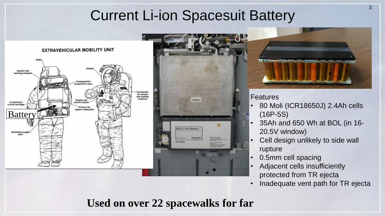
Current Li-ion Spacesuit Battery
Used on over 22 spacewalks for far
Battery
Features
• 80 Moli (ICR18650J) 2.4Ah cells
(16P-5S)
• 35Ah and 650 Wh at BOL (in 16-
20.5V window)
• Cell design unlikely to side wall
rupture
• 0.5mm cell spacing
• Adjacent cells insufficiently
protected from TR ejecta
• Inadequate vent path for TR ejecta
4
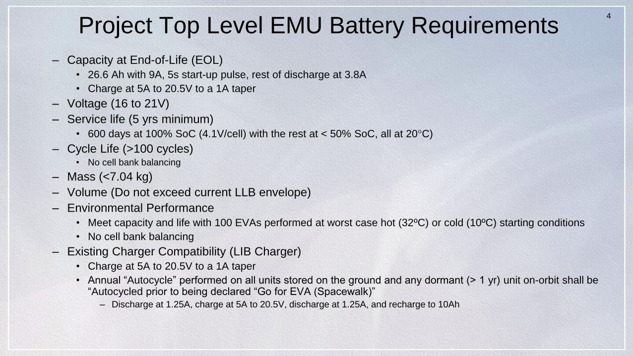
Project Top Level EMU Battery Requirements
– Capacity at End-of-Life (EOL)
• 26.6 Ah with 9A, 5s start-up pulse, rest of discharge at 3.8A
• Charge at 5A to 20.5V to a 1A taper
– Voltage (16 to 21V)
– Service life (5 yrs minimum)
• 600 days at 100% SoC (4.1V/cell) with the rest at < 50% SoC, all at 20°C)
– Cycle Life (>100 cycles)• No cell bank balancing
– Mass (<7.04 kg)
– Volume (Do not exceed current LLB envelope)
– Environmental Performance
• Meet capacity and life with 100 EVAs performed at worst case hot (32ºC) or cold (10ºC) starting conditions
• No cell bank balancing
– Existing Charger Compatibility (LIB Charger)
• Charge at 5A to 20.5V to a 1A taper
• Annual “Autocycle” performed on all units stored on the ground and any dormant (> 1 yr) unit on-orbit shall be “Autocycled prior to being declared “Go for EVA (Spacewalk)”
– Discharge at 1.25A, charge at 5A to 20.5V, discharge at 1.25A, and recharge to 10Ah
5
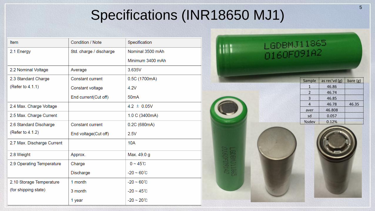
Specifications (INR18650 MJ1)
Sample as rec'vd (g) bare (g)
1 46.86
2 46.74
3 46.85
4 46.78 46.35
aver 46.808
sd 0.057
%sdev 0.12%
6
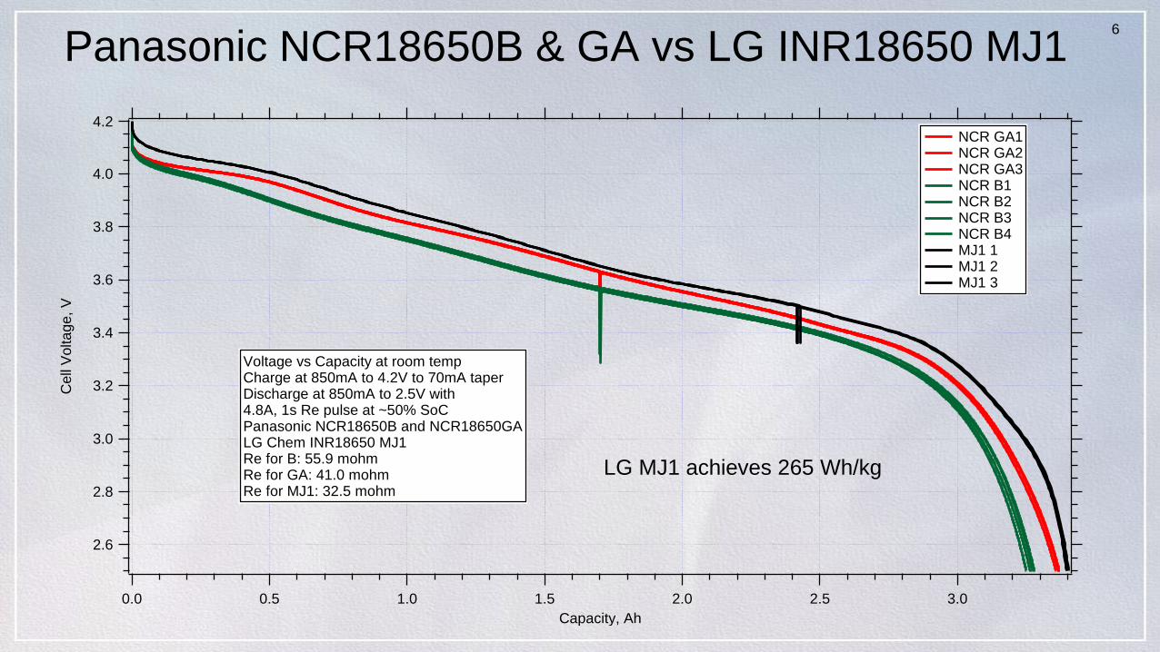
Panasonic NCR18650B & GA vs LG INR18650 MJ1
4.2
4.0
3.8
3.6
3.4
3.2
3.0
2.8
2.6
Cell
Vo
lta
ge
, V
3.02.52.01.51.00.50.0
Capacity, Ah
NCR GA1 NCR GA2 NCR GA3 NCR B1 NCR B2 NCR B3 NCR B4 MJ1 1 MJ1 2 MJ1 3
Voltage vs Capacity at room tempCharge at 850mA to 4.2V to 70mA taperDischarge at 850mA to 2.5V with4.8A, 1s Re pulse at ~50% SoCPanasonic NCR18650B and NCR18650GALG Chem INR18650 MJ1Re for B: 55.9 mohmRe for GA: 41.0 mohmRe for MJ1: 32.5 mohm
LG MJ1 achieves 265 Wh/kg

7
Ah, DC Re Comparison
3.4
3.3
3.2
3.1
3.0
2.9
2.8
Cap
acity,
Ah
10080604020
Cycle #
120
100
80
60
40
DC
resis
tan
ce
, mo
hm
Ah_NCRb7 Ah_NCRb8 Ah_NCRb9 Re_NCRb7 Re_NCRb8 Re_NCRb9 Ah_LG4 Ah_LG5 Ah_LG6 Re_LG4 Re_LG5 Re_LG6
Capacity, DC Re vs Cycle #Panasonic NCR B vs LG MJ1Charge at 800 mA to 4.2V, 70mA taperDischarge at 800 mA to 2.5V5A, 100ms pulse near 50% SoC
8
LG Chem’s New High Energy/Power Cell Design
• Advantages of the LG INR18650 MJ1 cell design
– Slightly higher Wh/L, Wh/kg vs competing designs from Panasonic
– Thicker cell can wall (0.0063” vs 0.0050”)
– LG wants their cell design to be used in space applications
– LG willing to implant our ISC device in special production runs of the
the MJ1 cell (enabling verification of battery PPR features)
– No cell PTC current limiting switch
• More compatible with high voltage missions because PTC is 30V device
• Lower internal resistance helps with power margins and blowing fusible links
– Slightly better cycle life
– Slightly less temperature dependent performance8
9
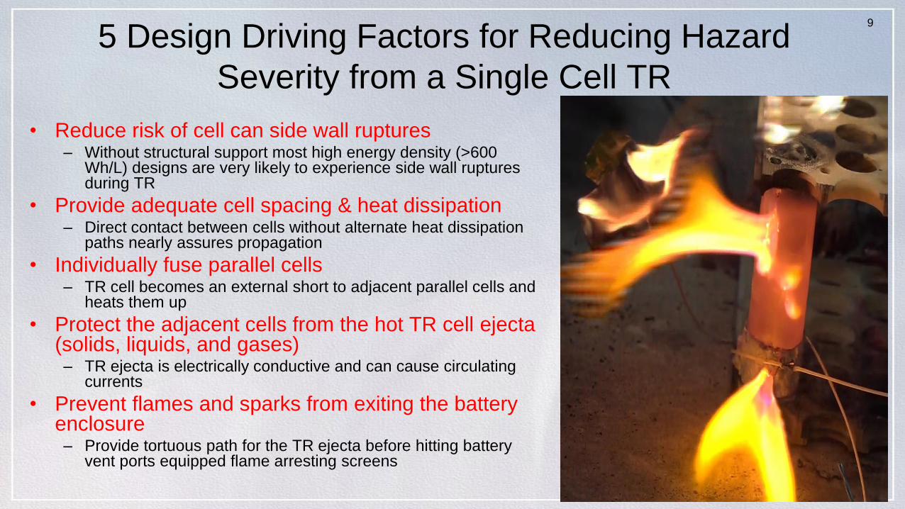
5 Design Driving Factors for Reducing Hazard
Severity from a Single Cell TR
• Reduce risk of cell can side wall ruptures– Without structural support most high energy density (>600
Wh/L) designs are very likely to experience side wall ruptures during TR
• Provide adequate cell spacing & heat dissipation– Direct contact between cells without alternate heat dissipation
paths nearly assures propagation
• Individually fuse parallel cells– TR cell becomes an external short to adjacent parallel cells and
heats them up
• Protect the adjacent cells from the hot TR cell ejecta(solids, liquids, and gases)– TR ejecta is electrically conductive and can cause circulating
currents
• Prevent flames and sparks from exiting the battery enclosure– Provide tortuous path for the TR ejecta before hitting battery
vent ports equipped flame arresting screens
10
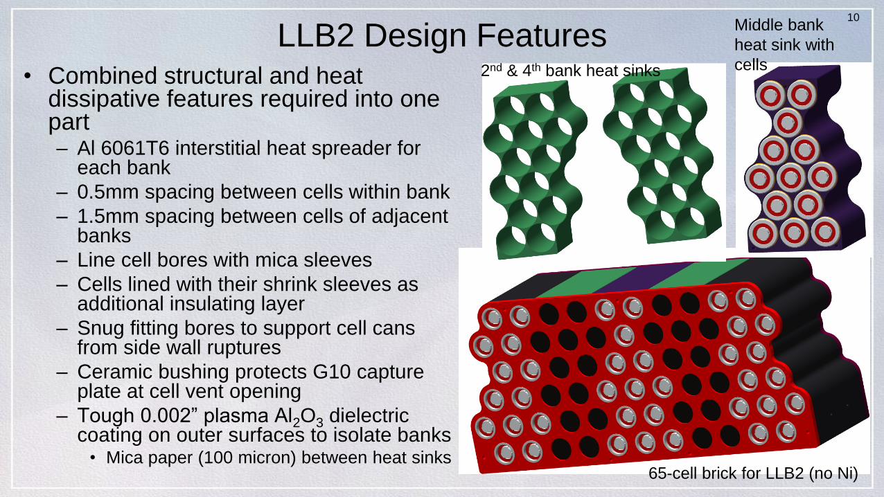
LLB2 Design Features• Combined structural and heat
dissipative features required into one part– Al 6061T6 interstitial heat spreader for
each bank
– 0.5mm spacing between cells within bank
– 1.5mm spacing between cells of adjacent banks
– Line cell bores with mica sleeves
– Cells lined with their shrink sleeves as additional insulating layer
– Snug fitting bores to support cell cans from side wall ruptures
– Ceramic bushing protects G10 capture plate at cell vent opening
– Tough 0.002” plasma Al2O3 dielectric coating on outer surfaces to isolate banks
• Mica paper (100 micron) between heat sinks
2nd & 4th bank heat sinks
Middle bank
heat sink with
cells
65-cell brick for LLB2 (no Ni)
11
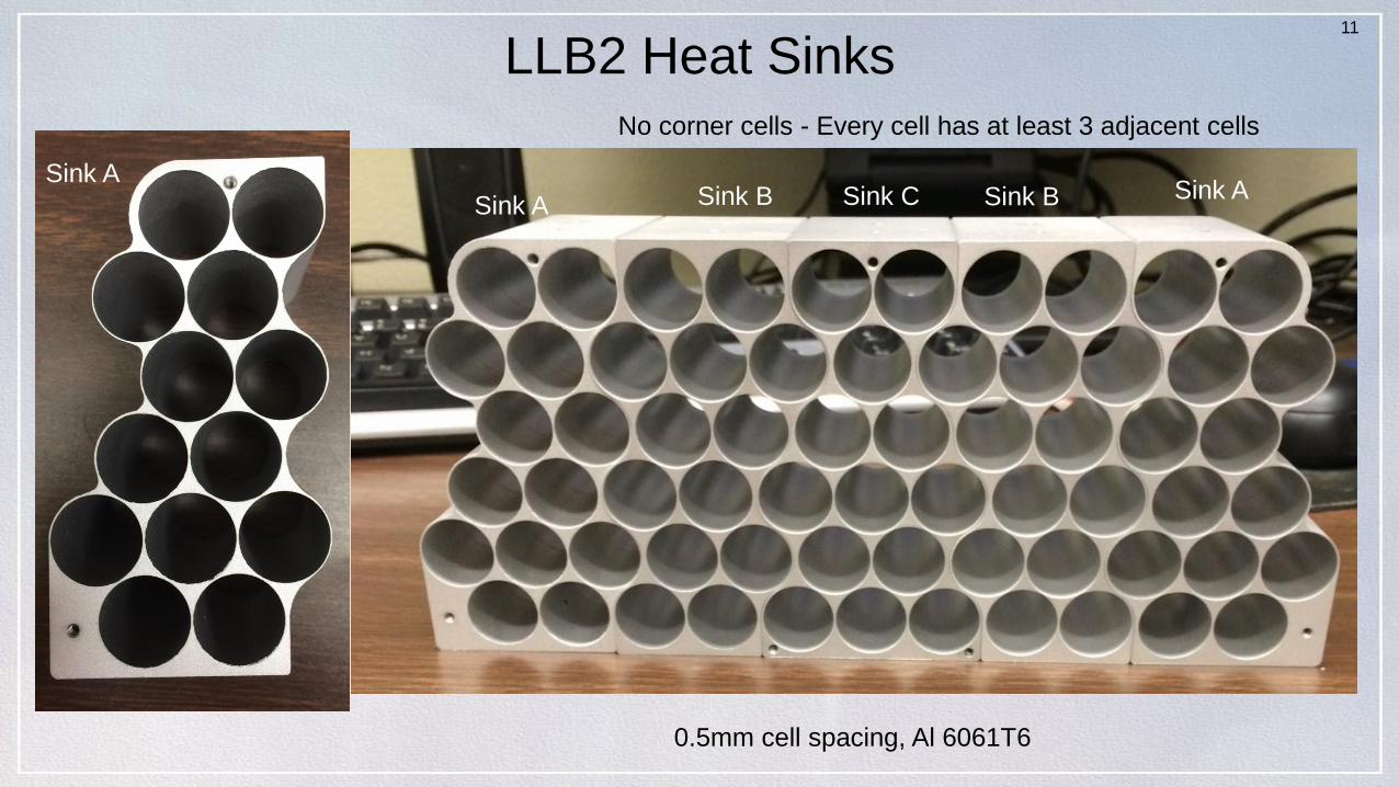
LLB2 Heat Sinks
0.5mm cell spacing, Al 6061T6
Sink ASink A
Sink ASink B Sink BSink C
No corner cells - Every cell has at least 3 adjacent cells
12
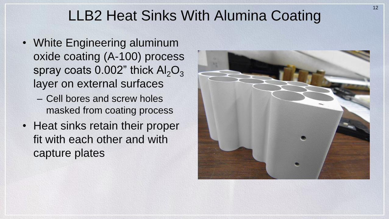
LLB2 Heat Sinks With Alumina Coating
• White Engineering aluminum
oxide coating (A-100) process
spray coats 0.002” thick Al2O3
layer on external surfaces
– Cell bores and screw holes
masked from coating process
• Heat sinks retain their proper
fit with each other and with
capture plates
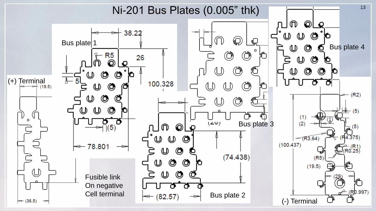
13Ni-201 Bus Plates (0.005” thk)
(+) Terminal
(-) Terminal
Bus plate 1
Bus plate 2
Bus plate 3
Bus plate 4
Fusible link
On negative
Cell terminal
14
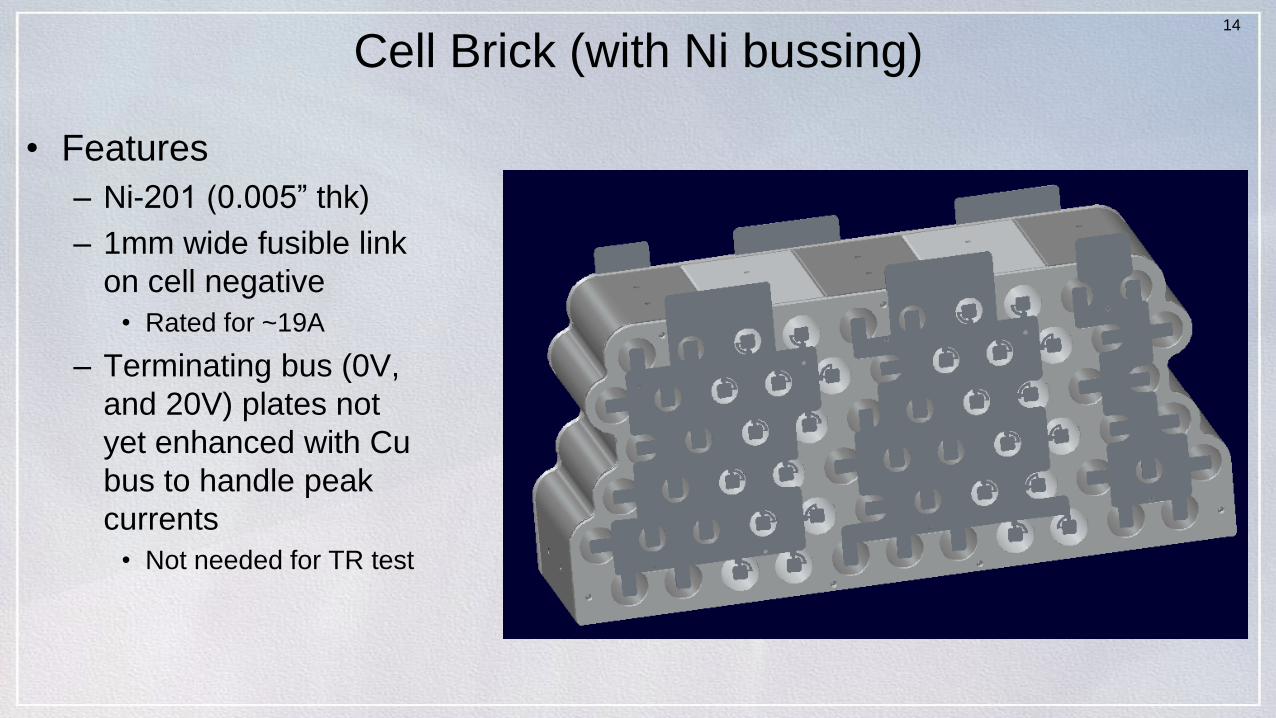
Cell Brick (with Ni bussing)
• Features
– Ni-201 (0.005” thk)
– 1mm wide fusible link
on cell negative
• Rated for ~19A
– Terminating bus (0V,
and 20V) plates not
yet enhanced with Cu
bus to handle peak
currents
• Not needed for TR test
15
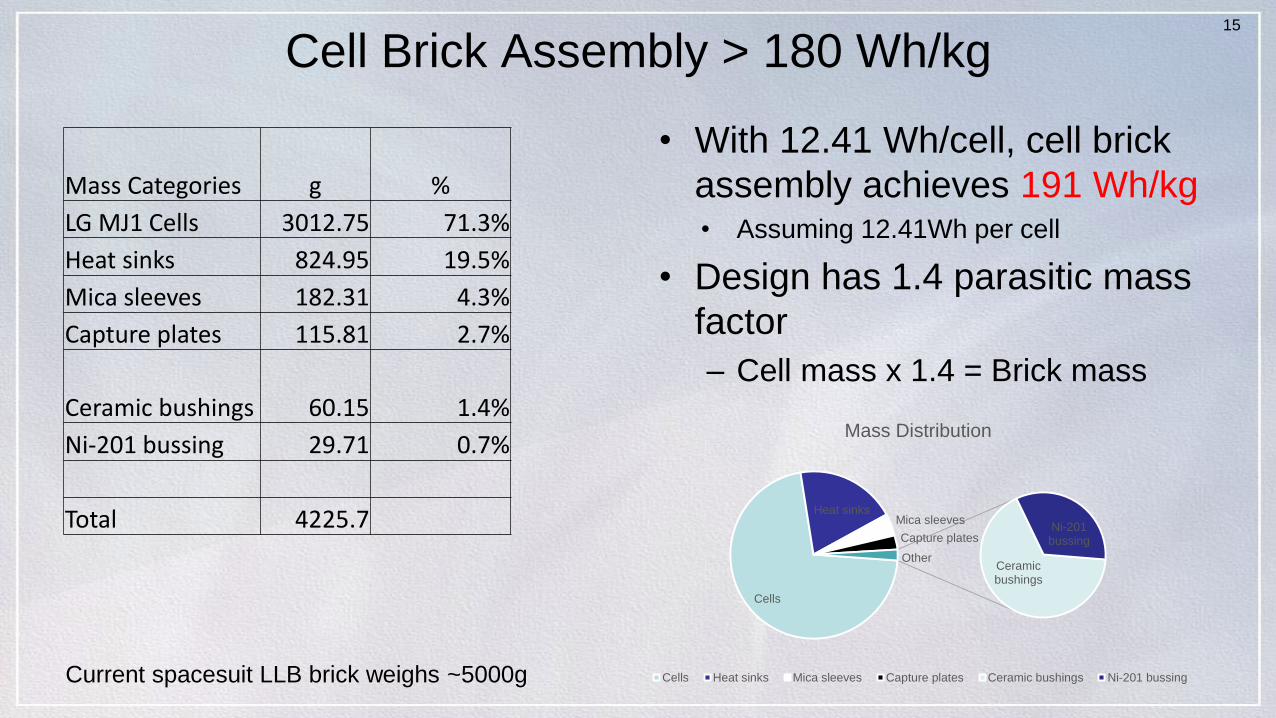
Cell Brick Assembly > 180 Wh/kg
• With 12.41 Wh/cell, cell brick
assembly achieves 191 Wh/kg• Assuming 12.41Wh per cell
• Design has 1.4 parasitic mass
factor
– Cell mass x 1.4 = Brick mass
Cells
Heat sinksMica sleeves
Capture plates
Ceramic bushings
Ni-201 bussing
Other
Mass Distribution
Cells Heat sinks Mica sleeves Capture plates Ceramic bushings Ni-201 bussingCurrent spacesuit LLB brick weighs ~5000g
Mass Categories g %
LG MJ1 Cells 3012.75 71.3%
Heat sinks 824.95 19.5%
Mica sleeves 182.31 4.3%
Capture plates 115.81 2.7%
Ceramic bushings 60.15 1.4%
Ni-201 bussing 29.71 0.7%
Total 4225.7
16
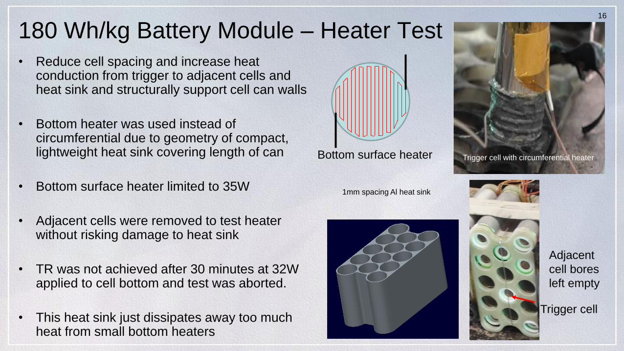
180 Wh/kg Battery Module – Heater Test
• Reduce cell spacing and increase heat conduction from trigger to adjacent cells and heat sink and structurally support cell can walls
• Bottom heater was used instead of circumferential due to geometry of compact, lightweight heat sink covering length of can
• Bottom surface heater limited to 35W
• Adjacent cells were removed to test heater without risking damage to heat sink
• TR was not achieved after 30 minutes at 32W applied to cell bottom and test was aborted.
• This heat sink just dissipates away too much heat from small bottom heaters
1mm spacing Al heat sink
Trigger cell with circumferential heaterBottom surface heater
Trigger cell
Adjacent
cell bores
left empty
17
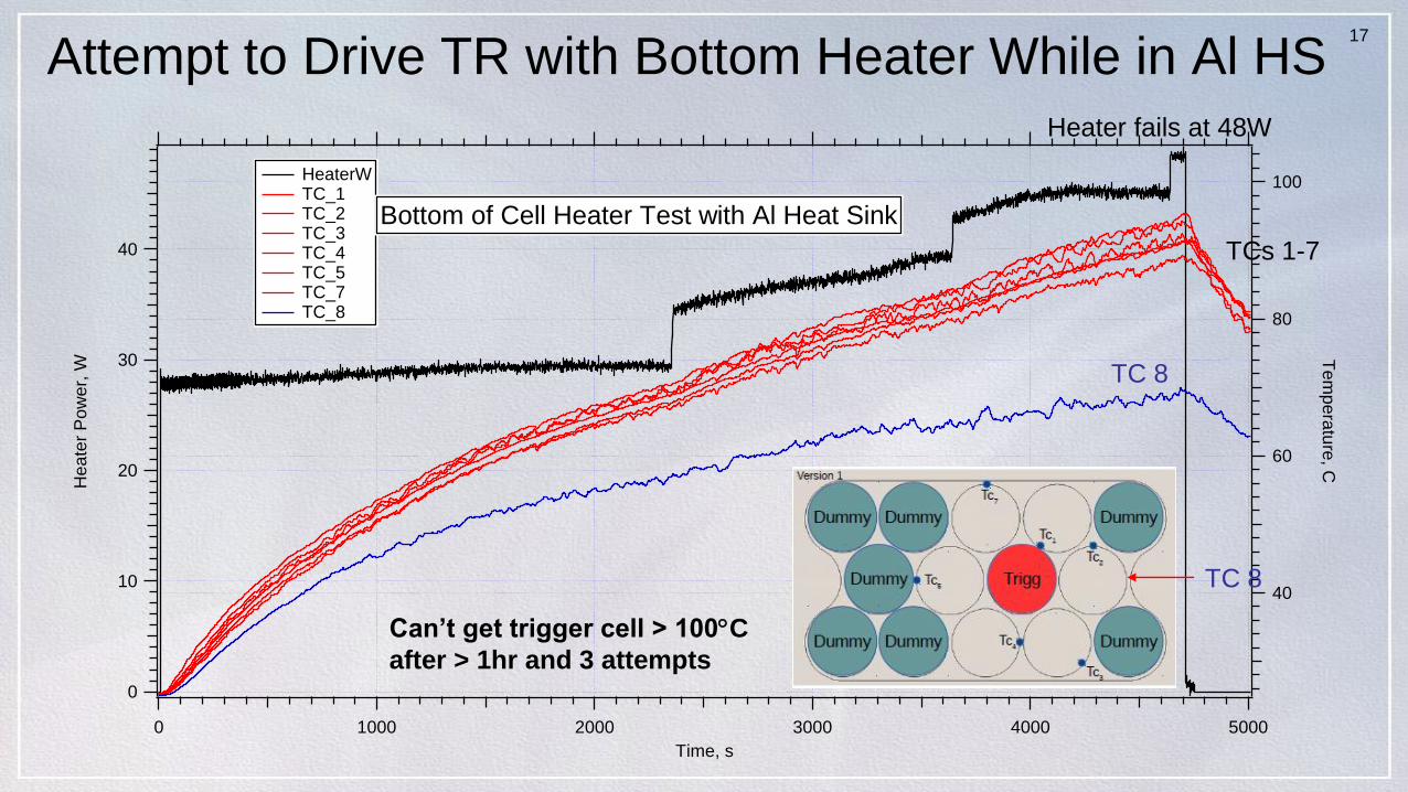
Attempt to Drive TR with Bottom Heater While in Al HS
40
30
20
10
0
He
ate
r P
ow
er,
W
500040003000200010000
Time, s
100
80
60
40
Te
mp
era
ture
, C
HeaterW TC_1 TC_2 TC_3 TC_4 TC_5 TC_7 TC_8
Bottom of Cell Heater Test with Al Heat Sink
TCs 1-7
TC 8
TC 8
Heater fails at 48W
Can’t get trigger cell > 100C
after > 1hr and 3 attempts
18
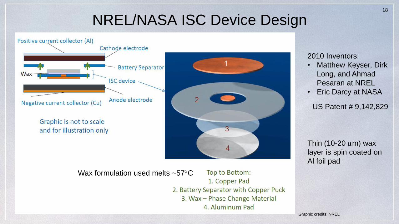
NREL/NASA ISC Device Design
Wax formulation used melts ~57C
US Patent # 9,142,829
2010 Inventors:
• Matthew Keyser, Dirk
Long, and Ahmad
Pesaran at NREL
• Eric Darcy at NASA
Graphic credits: NREL
Thin (10-20 m) wax
layer is spin coated on
Al foil pad
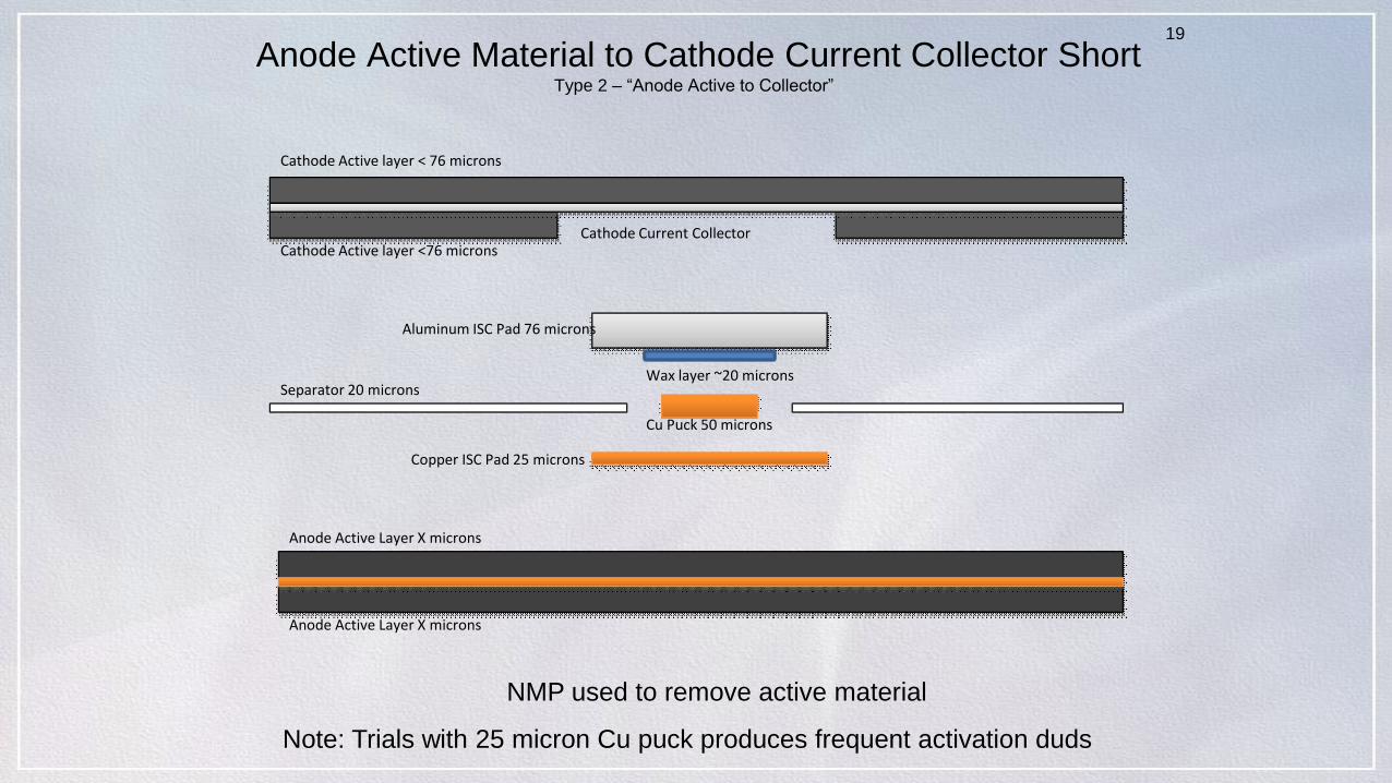
Anode Active Material to Cathode Current Collector ShortType 2 – “Anode Active to Collector”
NMP used to remove active material
19
Cathode Active layer < 76 microns
Aluminum ISC Pad 76 microns
Cu Puck 50 microns
Separator 20 microns
Copper ISC Pad 25 microns
Anode Active Layer X microns
Cathode Active layer <76 microns
Anode Active Layer X microns
Wax layer ~20 microns
Cathode Current Collector
Note: Trials with 25 micron Cu puck produces frequent activation duds
20
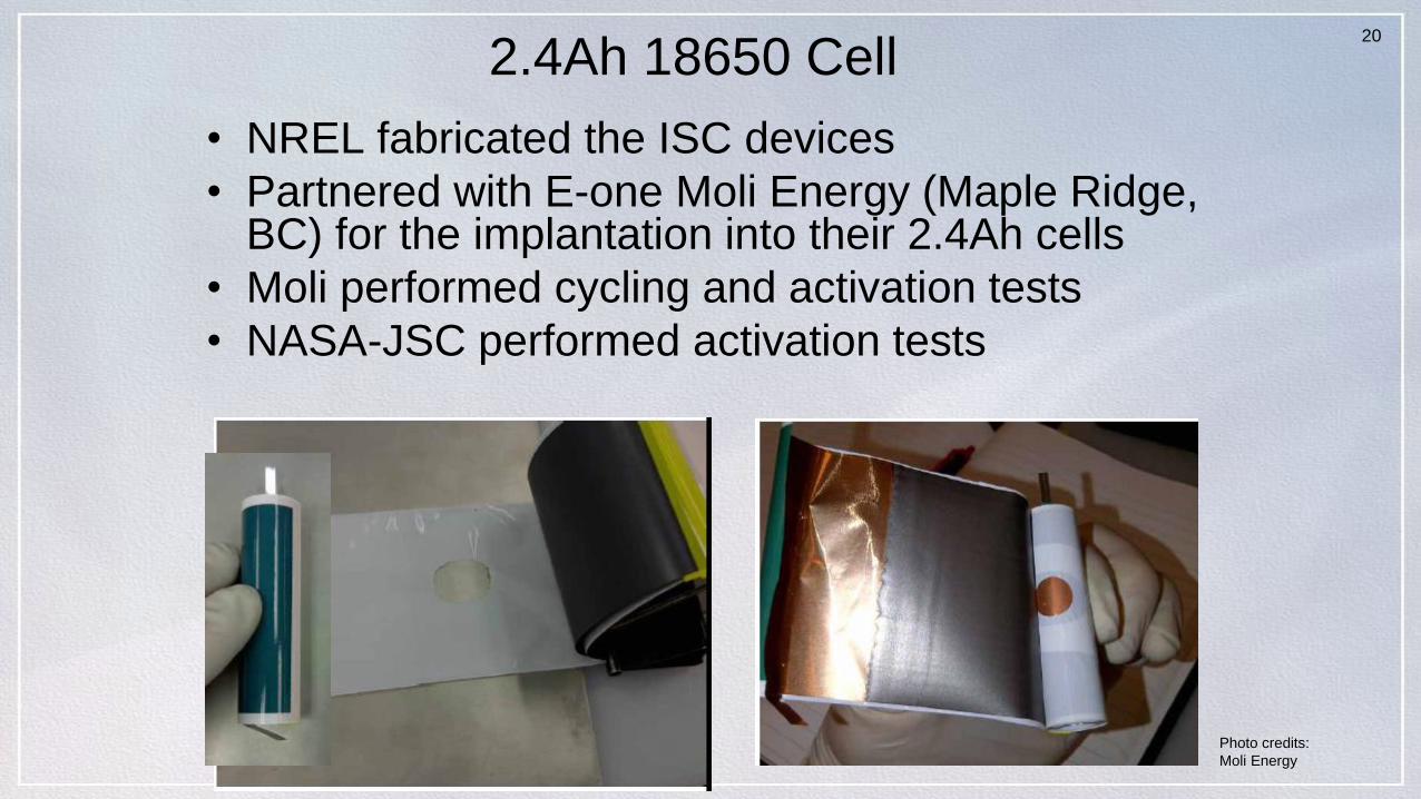
2.4Ah 18650 Cell
• NREL fabricated the ISC devices
• Partnered with E-one Moli Energy (Maple Ridge, BC) for the implantation into their 2.4Ah cells
• Moli performed cycling and activation tests
• NASA-JSC performed activation tests
Photo credits:
Moli Energy
21
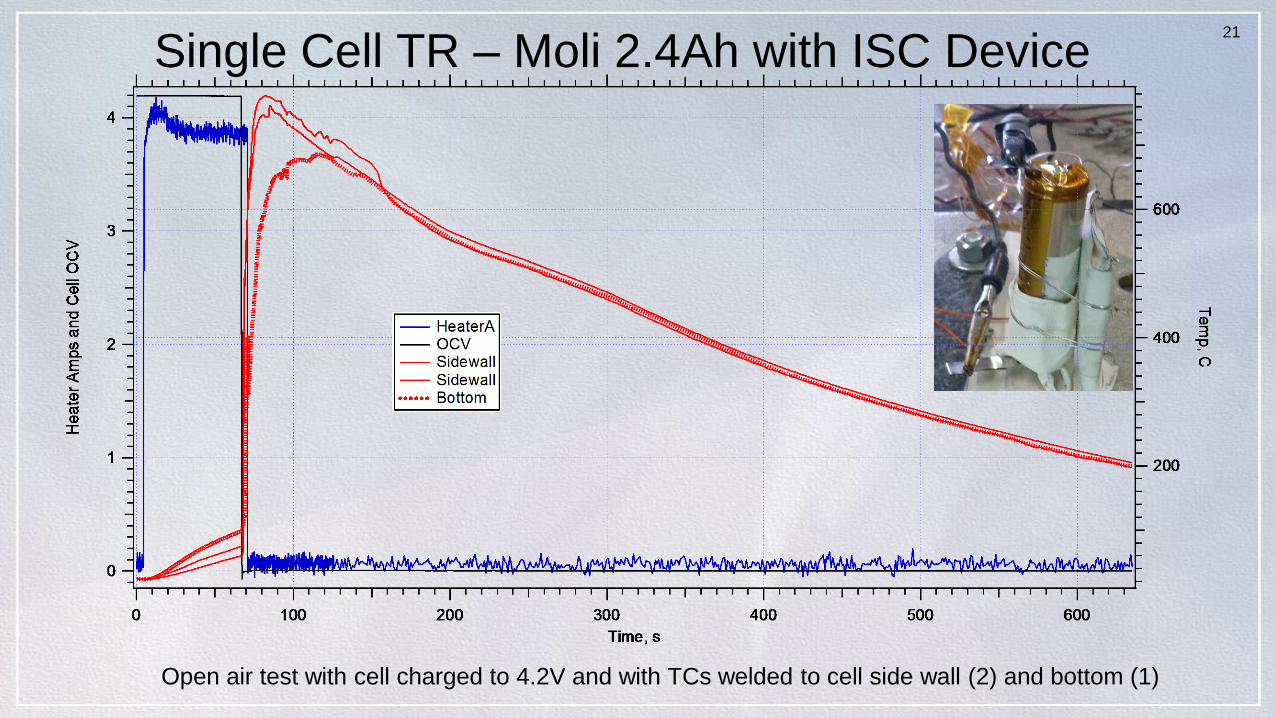
Single Cell TR – Moli 2.4Ah with ISC Device
Open air test with cell charged to 4.2V and with TCs welded to cell side wall (2) and bottom (1)
22
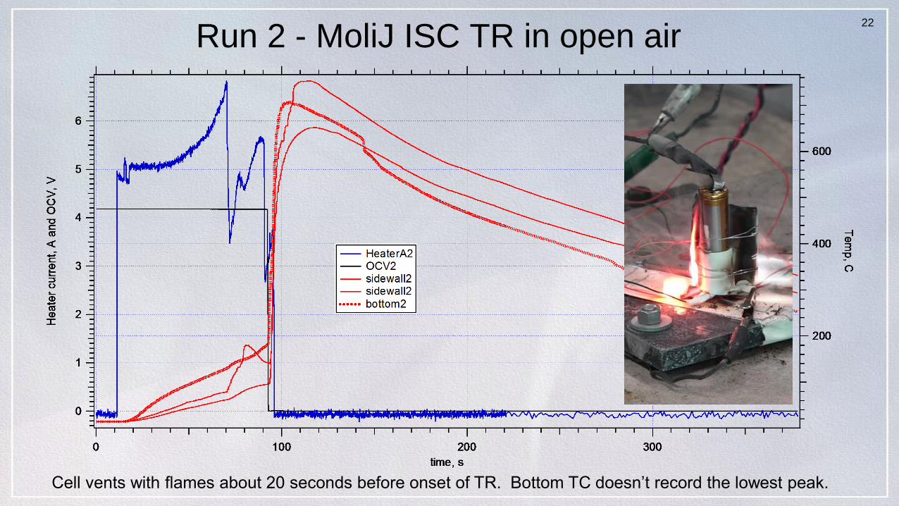
Run 2 - MoliJ ISC TR in open air
Cell vents with flames about 20 seconds before onset of TR. Bottom TC doesn’t record the lowest peak.
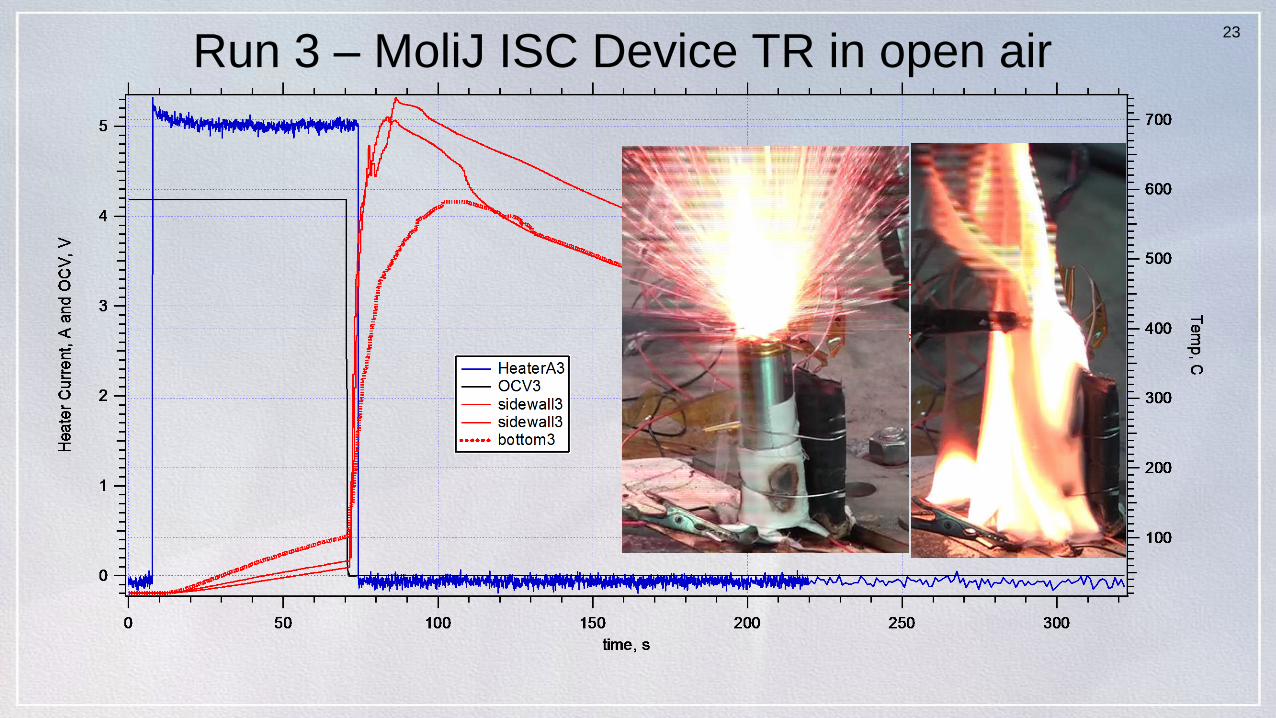
23
Run 3 – MoliJ ISC Device TR in open air
24
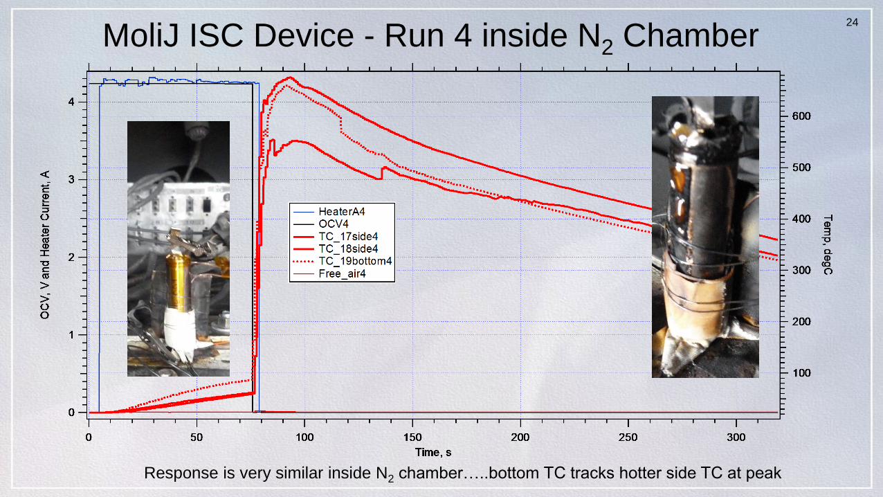
MoliJ ISC Device - Run 4 inside N2 Chamber
Response is very similar inside N2 chamber…..bottom TC tracks hotter side TC at peak
25
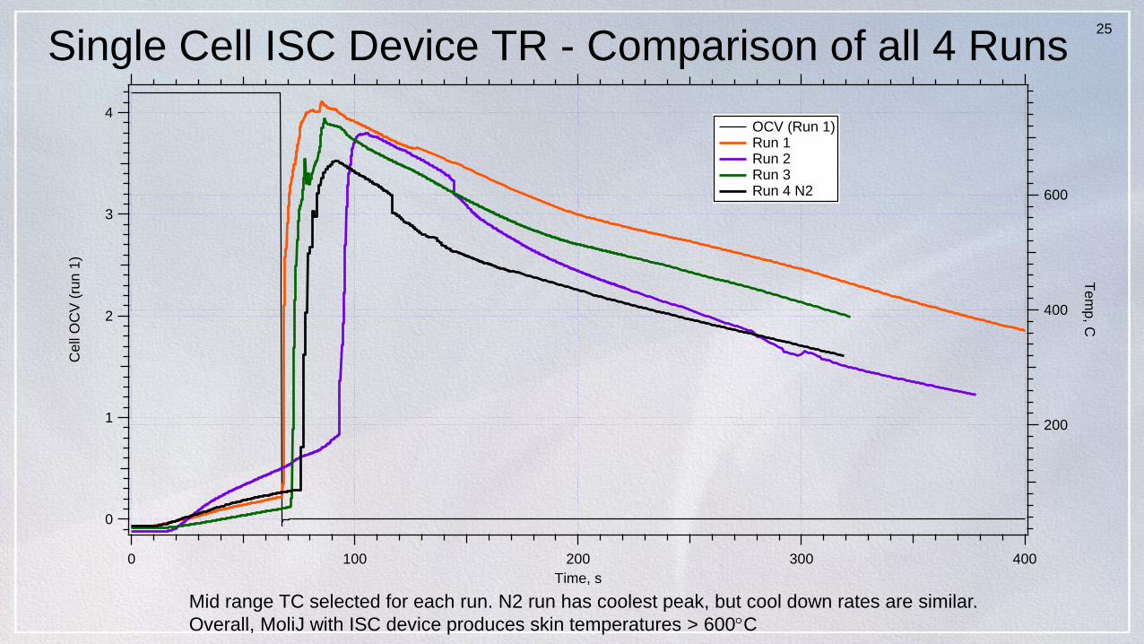
Single Cell ISC Device TR - Comparison of all 4 Runs
4
3
2
1
0
Cell
OC
V (
run
1)
4003002001000
Time, s
600
400
200
Te
mp
, C
OCV (Run 1) Run 1 Run 2 Run 3 Run 4 N2
Mid range TC selected for each run. N2 run has coolest peak, but cool down rates are similar.
Overall, MoliJ with ISC device produces skin temperatures > 600C
26
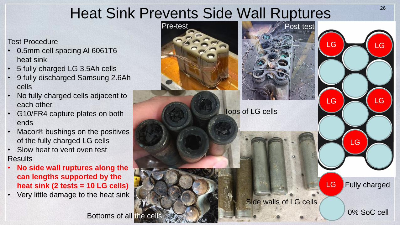
Heat Sink Prevents Side Wall Ruptures
LG
LGLG
LG LG
LG
0% SoC cell
Fully charged
Test Procedure
• 0.5mm cell spacing Al 6061T6
heat sink
• 5 fully charged LG 3.5Ah cells
• 9 fully discharged Samsung 2.6Ah
cells
• No fully charged cells adjacent to
each other
• G10/FR4 capture plates on both
ends
• Macor® bushings on the positives
of the fully charged LG cells
• Slow heat to vent oven test
Results
• No side wall ruptures along the
can lengths supported by the
heat sink (2 tests = 10 LG cells)
• Very little damage to the heat sink
Tops of LG cells
Pre-test Post-test
Side walls of LG cells
Bottoms of all the cells
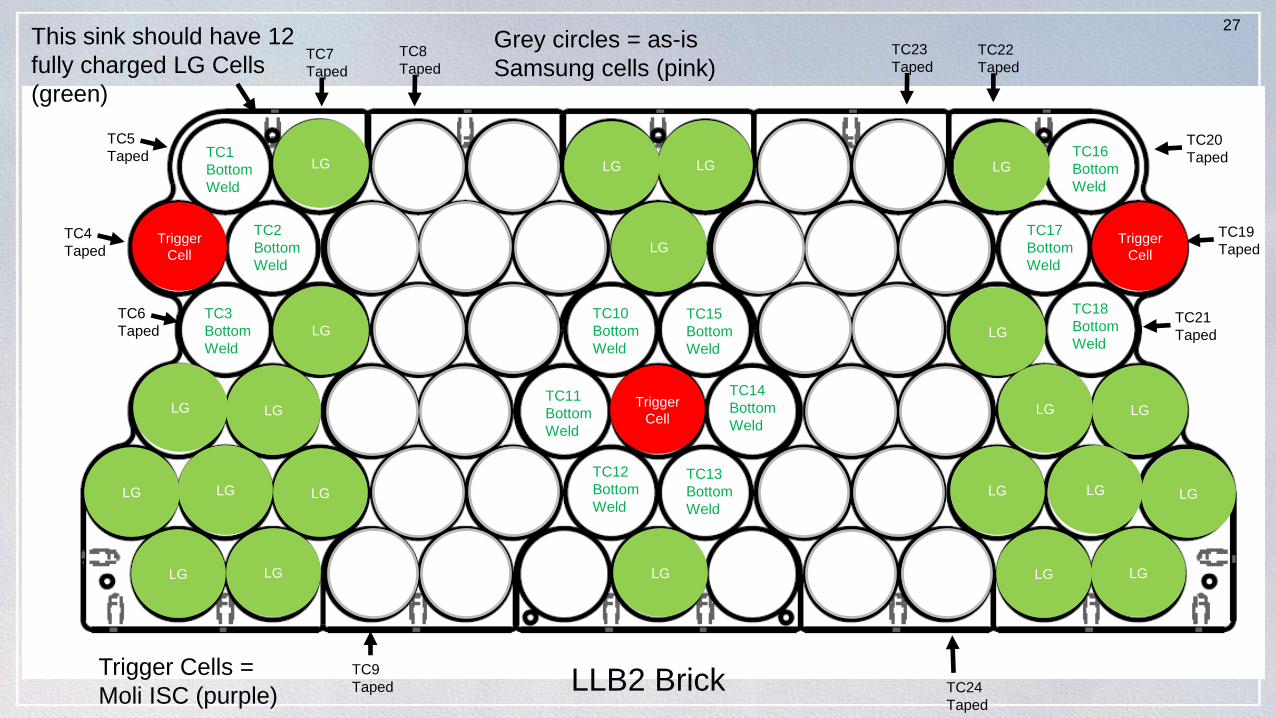
27This sink should have 12
fully charged LG Cells
(green)
Grey circles = as-is
Samsung cells (pink)
Trigger Cells =
Moli ISC (purple)
TC1
Bottom
Weld
TC2
Bottom
Weld
TC3
Bottom
Weld
TC4
Taped
TC6
Taped
TC5
Taped
TC7
Taped
TC8
Taped
TC9
Taped
Trigger
Cell
TC10
Bottom
Weld
TC11
Bottom
Weld
TC12
Bottom
Weld
TC13
Bottom
Weld
TC14
Bottom
Weld
TC15
Bottom
Weld
TC16
Bottom
Weld
TC17
Bottom
Weld
TC18
Bottom
Weld
TC19
Taped
TC20
Taped
TC21
Taped
TC22
Taped
TC23
Taped
TC24
Taped
Trigger
Cell
Trigger
Cell
LG
LGLGLG
LG
LG
LG
LG
LGLG
LG
LG
LG
LG
LGLG
LG
LGLG
LG
LG
LG
LLB2 Brick
28
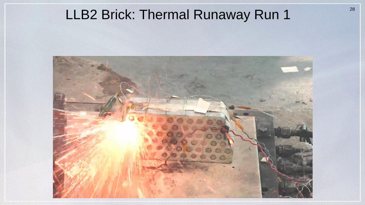
LLB2 Brick: Thermal Runaway Run 1
4.20/
--
3.77
/
--
29
5
4
3
2
1
0
Hea
ter
Curr
en
t, A
an
d O
CV
, V
7006005004003002001000
time, s
120
100
80
60
40
20
Te
mp
, C
OCV3 HeaterA3 TC1 TC2 TC3 TC4 TC5 TC6 TC7 TC8 TC9
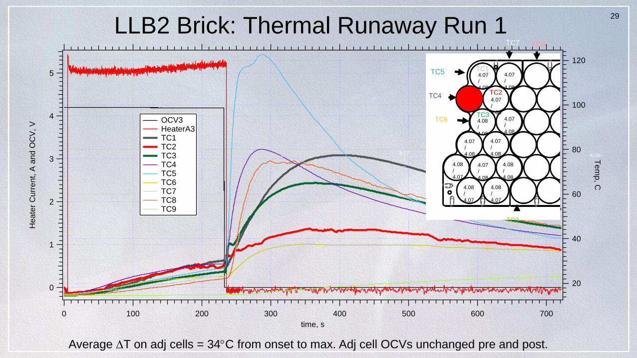
LLB2 Brick: Thermal Runaway Run 1
4.20/--
4.20/
--
3.77
/
--
TC1
TC2
TC3
TC4
TC5
TC7 TC8
TC6
TC9
4.07
/
4.08
4.07
/
4.08
4.07
/
4.08
4.08
/
4.08
4.07
/
4.08
4.07
/
4.08
4.07
/
4.08
4.08
/
4.07
4.07
/
4.08
4.08
/
4.08
4.08
/
4.07
4.08
/
4.07
Average T on adj cells = 34C from onset to max. Adj cell OCVs unchanged pre and post.
30
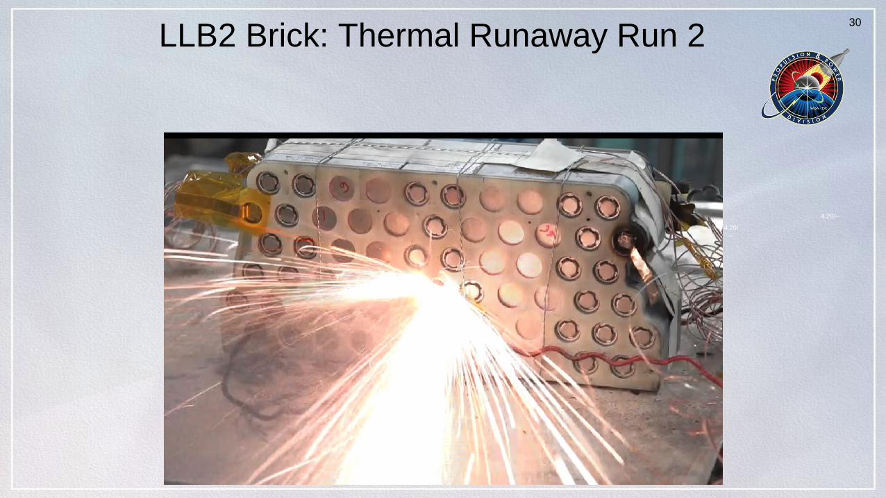
LLB2 Brick: Thermal Runaway Run 2
4.20/--
4.20/
--
31
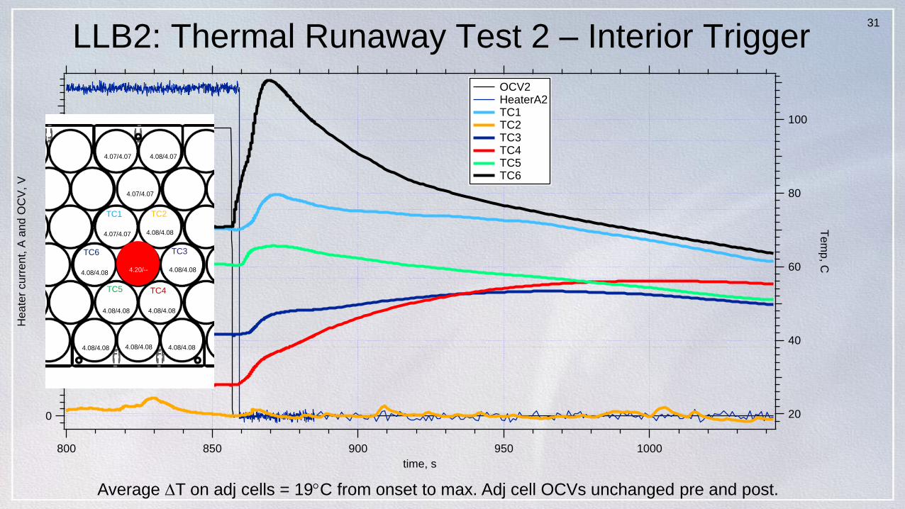
LLB2: Thermal Runaway Test 2 – Interior Trigger
4
3
2
1
0
Hea
ter
cu
rre
nt,
A a
nd
OC
V,
V
1000950900850800
time, s
100
80
60
40
20
Te
mp
, C OCV2 HeaterA2 TC1 TC2 TC3 TC4 TC5 TC6
Average T on adj cells = 19C from onset to max. Adj cell OCVs unchanged pre and post.
TC1 TC2
TC3
TC4TC5
TC6
4.07/4.07 4.08/4.07
4.07/4.07
4.07/4.07 4.08/4.08
4.08/4.084.08/4.08
4.08/4.08 4.08/4.08
4.08/4.08 4.08/4.08 4.08/4.08
4.20/--
32
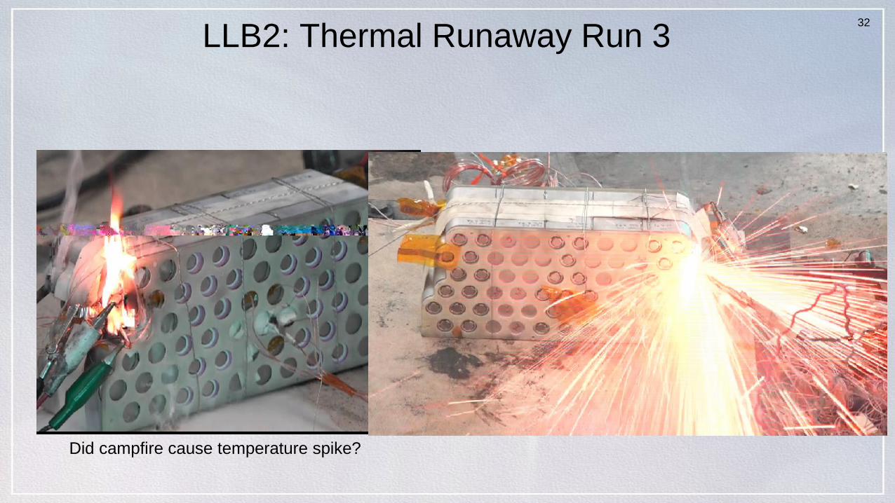
LLB2: Thermal Runaway Run 3
4.20/--
Did campfire cause temperature spike?
33
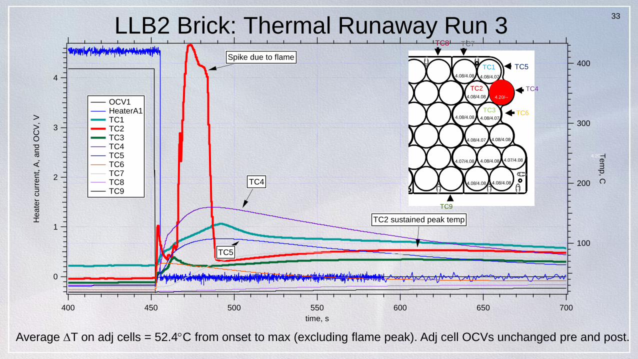
4
3
2
1
0
Hea
ter
cu
rre
nt,
A,
an
d O
CV
, V
700650600550500450400
time, s
400
300
200
100
Te
mp
, C
OCV1 HeaterA1 TC1 TC2 TC3 TC4 TC5 TC6 TC7 TC8 TC9
TC4
TC5
TC2 sustained peak temp
Spike due to flame
LLB2 Brick: Thermal Runaway Run 3
4.20/--
TC1
TC2
TC3
TC4
TC5
TC7TC8
TC6
TC9
4.08/4.08 4.08/4.07
4.08/4.08 4.20/--
4.08/4.08 4.08/4.07
4.08/4.07 4.08/4.08
4.07/4.08 4.08/4.08 4.07/4.08
4.08/4.08 4.08/4.08
Average T on adj cells = 52.4C from onset to max (excluding flame peak). Adj cell OCVs unchanged pre and post.
34
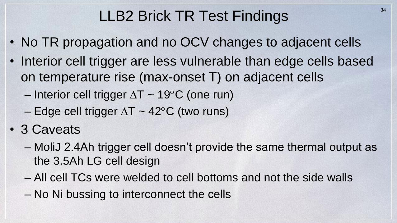
LLB2 Brick TR Test Findings
• No TR propagation and no OCV changes to adjacent cells
• Interior cell trigger are less vulnerable than edge cells based
on temperature rise (max-onset T) on adjacent cells
– Interior cell trigger T ~ 19C (one run)
– Edge cell trigger T ~ 42C (two runs)
• 3 Caveats
– MoliJ 2.4Ah trigger cell doesn’t provide the same thermal output as
the 3.5Ah LG cell design
– All cell TCs were welded to cell bottoms and not the side walls
– No Ni bussing to interconnect the cells
35
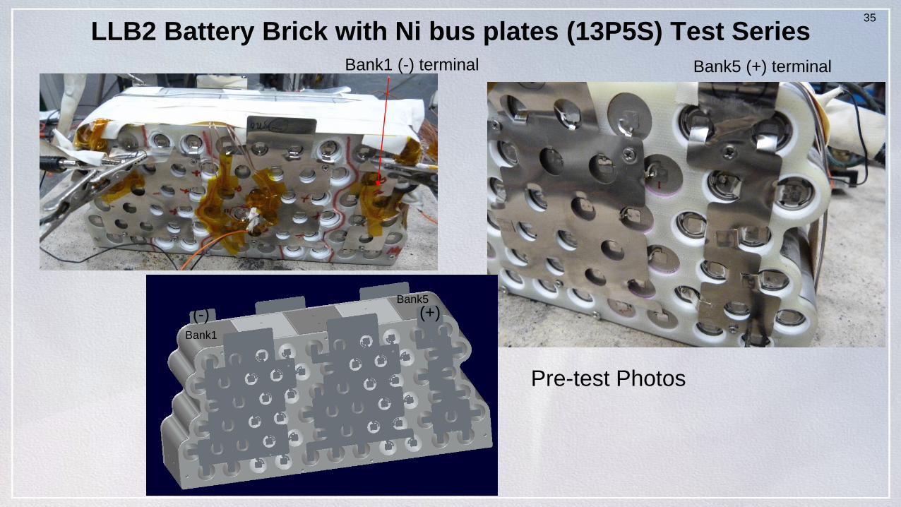
LLB2 Battery Brick with Ni bus plates (13P5S) Test SeriesBank1 (-) terminal Bank5 (+) terminal
(-) (+)
Bank1
Bank5
Pre-test Photos
36
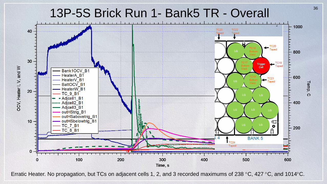
13P-5S Brick Run 1- Bank5 TR - Overall
Erratic Heater. No propagation, but TCs on adjacent cells 1, 2, and 3 recorded maximums of 238 C, 427 C, and 1014C.
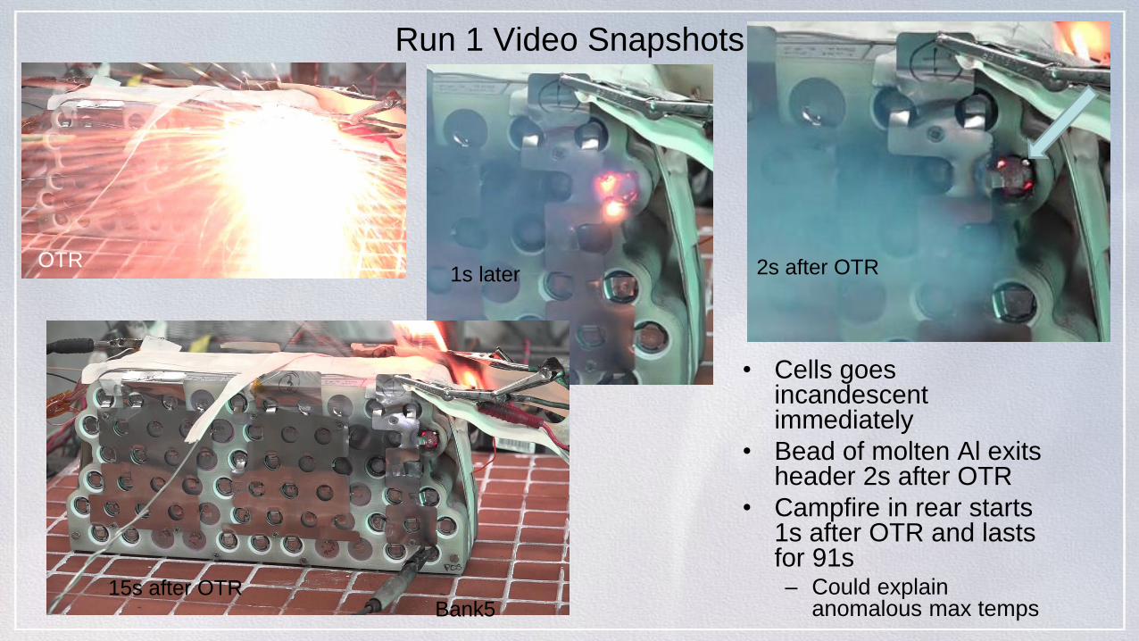
Run 1 Video Snapshots
• Cells goes incandescent immediately
• Bead of molten Al exits header 2s after OTR
• Campfire in rear starts 1s after OTR and lasts for 91s– Could explain
anomalous max temps
OTR1s later 2s after OTR
15s after OTRBank5
38
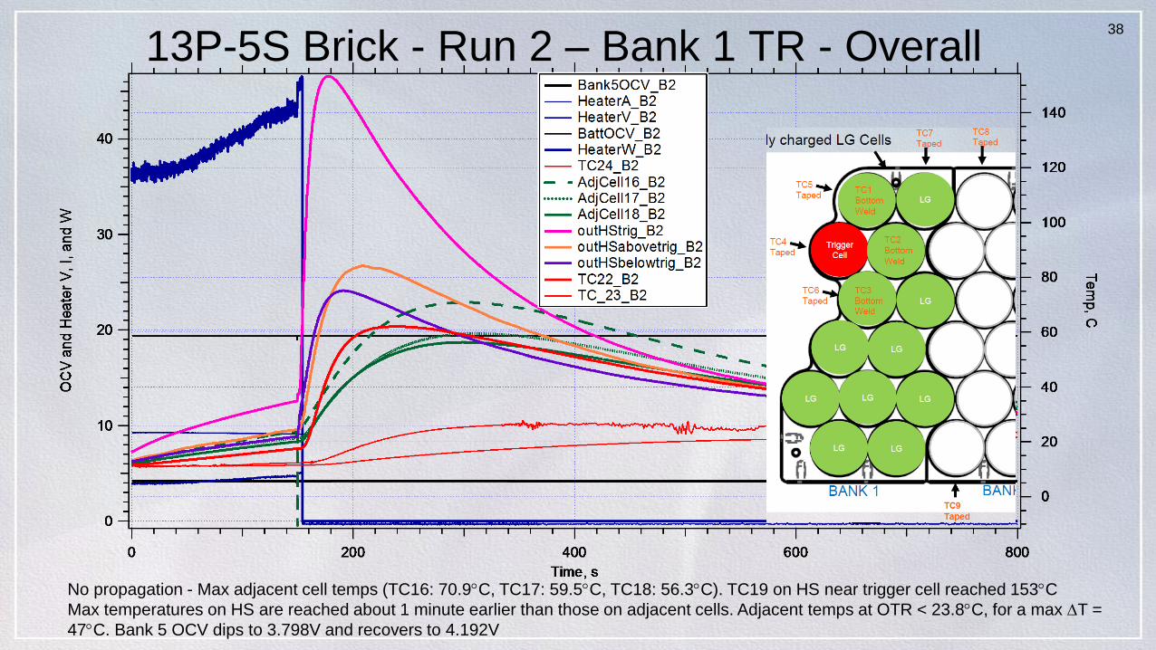
13P-5S Brick - Run 2 – Bank 1 TR - Overall
No propagation - Max adjacent cell temps (TC16: 70.9C, TC17: 59.5C, TC18: 56.3C). TC19 on HS near trigger cell reached 153C
Max temperatures on HS are reached about 1 minute earlier than those on adjacent cells. Adjacent temps at OTR < 23.8C, for a max T =
47C. Bank 5 OCV dips to 3.798V and recovers to 4.192V
39
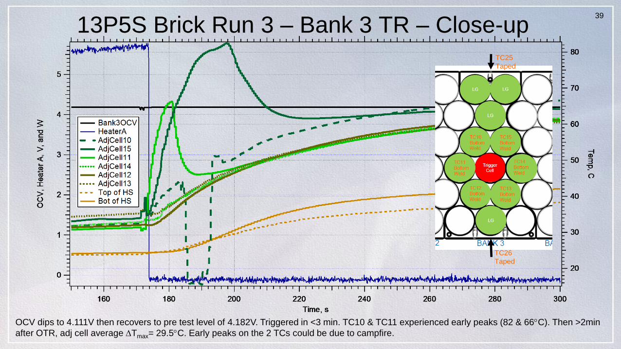
13P5S Brick Run 3 – Bank 3 TR – Close-up
OCV dips to 4.111V then recovers to pre test level of 4.182V. Triggered in <3 min. TC10 & TC11 experienced early peaks (82 & 66C). Then >2min
after OTR, adj cell average Tmax= 29.5C. Early peaks on the 2 TCs could be due to campfire.
TC26
Taped
TC25
Taped
40
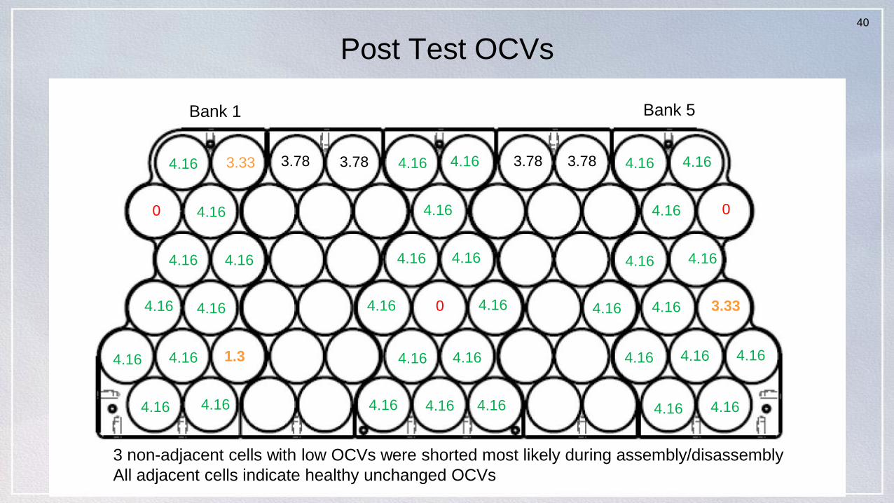
Post Test OCVs
4.16 4.16
4.16
4.16 4.16
4.16
4.16
4.16
4.16
4.16 4.16
3.33
0
4.163.33
1.3
4.16
4.16 4.16 4.16
4.16 4.16
4.16 4.16
4.164.16
4.16
0
04.16 4.16
4.16 4.16
4.16 4.16 4.16
4.16 4.16
4.16
4.163.78 3.78 3.78 3.78
3 non-adjacent cells with low OCVs were shorted most likely during assembly/disassembly
All adjacent cells indicate healthy unchanged OCVs
Bank 5Bank 1
41
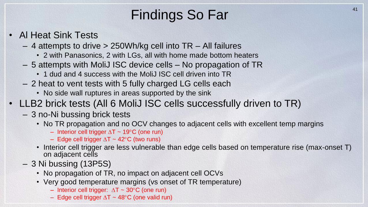
Findings So Far
• Al Heat Sink Tests– 4 attempts to drive > 250Wh/kg cell into TR – All failures
• 2 with Panasonics, 2 with LGs, all with home made bottom heaters
– 5 attempts with MoliJ ISC device cells – No propagation of TR• 1 dud and 4 success with the MoliJ ISC cell driven into TR
– 2 heat to vent tests with 5 fully charged LG cells each• No side wall ruptures in areas supported by the sink
• LLB2 brick tests (All 6 MoliJ ISC cells successfully driven to TR)– 3 no-Ni bussing brick tests
• No TR propagation and no OCV changes to adjacent cells with excellent temp margins– Interior cell trigger T ~ 19C (one run)
– Edge cell trigger T ~ 42C (two runs)
• Interior cell trigger are less vulnerable than edge cells based on temperature rise (max-onset T) on adjacent cells
– 3 Ni bussing (13P5S)• No propagation of TR, no impact on adjacent cell OCVs
• Very good temperature margins (vs onset of TR temperature)– Interior cell trigger: T ~ 30C (one run)
– Edge cell trigger T ~ 48C (one valid run)
42
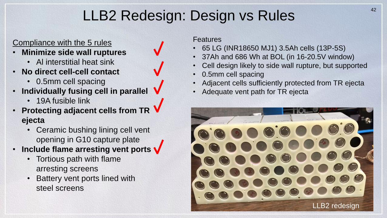
LLB2 Redesign: Design vs Rules
LLB2 redesign
Features
• 65 LG (INR18650 MJ1) 3.5Ah cells (13P-5S)
• 37Ah and 686 Wh at BOL (in 16-20.5V window)
• Cell design likely to side wall rupture, but supported
• 0.5mm cell spacing
• Adjacent cells sufficiently protected from TR ejecta
• Adequate vent path for TR ejecta
Compliance with the 5 rules
• Minimize side wall ruptures
• Al interstitial heat sink
• No direct cell-cell contact
• 0.5mm cell spacing
• Individually fusing cell in parallel
• 19A fusible link
• Protecting adjacent cells from TR
ejecta
• Ceramic bushing lining cell vent
opening in G10 capture plate
• Include flame arresting vent ports
• Tortious path with flame
arresting screens
• Battery vent ports lined with
steel screens
43
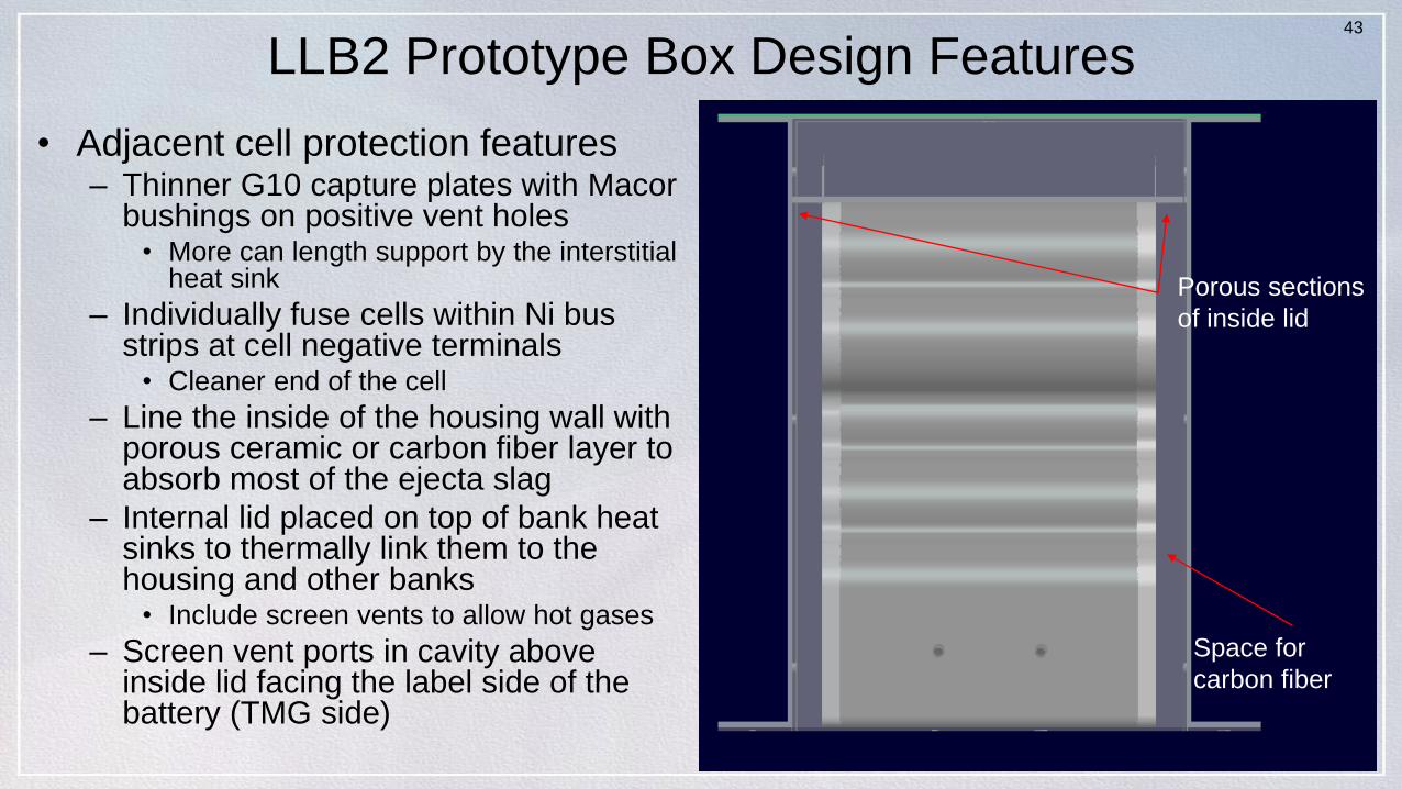
LLB2 Prototype Box Design Features
• Adjacent cell protection features– Thinner G10 capture plates with Macor
bushings on positive vent holes• More can length support by the interstitial
heat sink
– Individually fuse cells within Ni bus strips at cell negative terminals
• Cleaner end of the cell
– Line the inside of the housing wall with porous ceramic or carbon fiber layer to absorb most of the ejecta slag
– Internal lid placed on top of bank heat sinks to thermally link them to the housing and other banks
• Include screen vents to allow hot gases
– Screen vent ports in cavity above inside lid facing the label side of the battery (TMG side)
Porous sections
of inside lid
Space for
carbon fiber
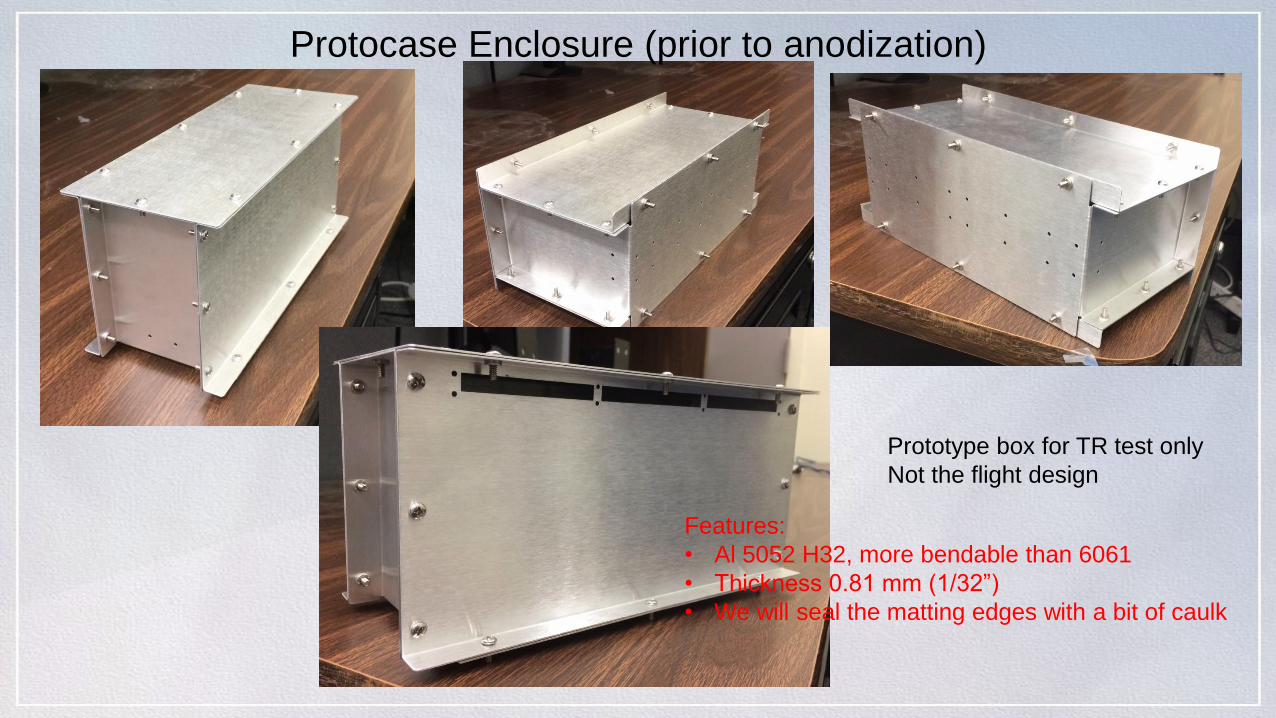
Protocase Enclosure (prior to anodization)
Prototype box for TR test only
Not the flight design
Features:
• Al 5052 H32, more bendable than 6061
• Thickness 0.81 mm (1/32”)
• We will seal the matting edges with a bit of caulk
45
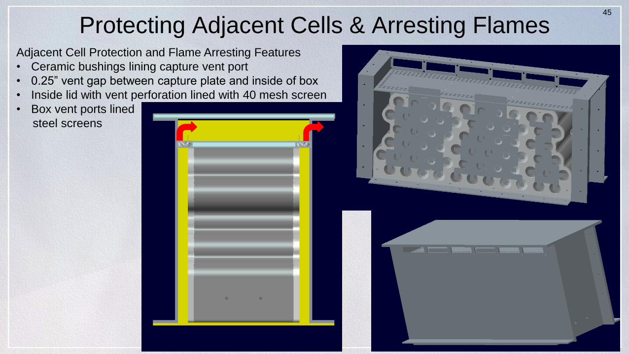
Protecting Adjacent Cells & Arresting FlamesAdjacent Cell Protection and Flame Arresting Features
• Ceramic bushings lining capture vent port
• 0.25” vent gap between capture plate and inside of box
• Inside lid with vent perforation lined with 40 mesh screen
• Box vent ports lined
steel screens
46
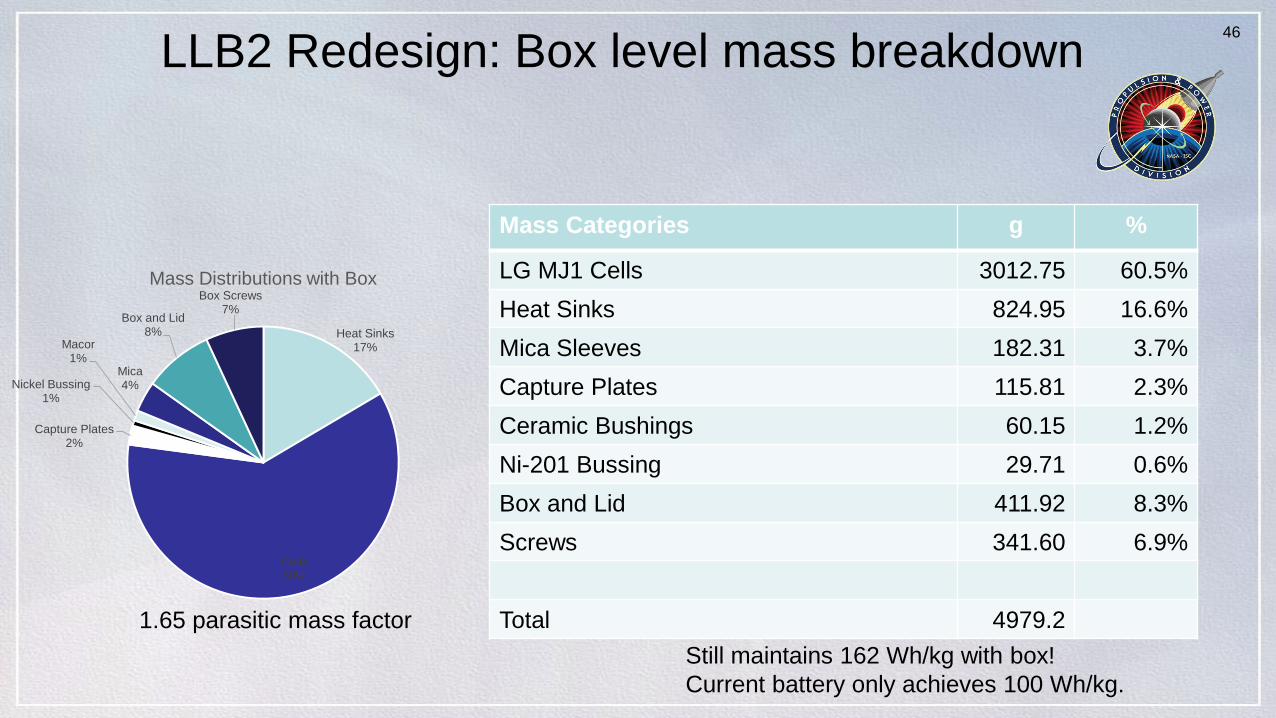
LLB2 Redesign: Box level mass breakdown
Mass Categories g %
LG MJ1 Cells 3012.75 60.5%
Heat Sinks 824.95 16.6%
Mica Sleeves 182.31 3.7%
Capture Plates 115.81 2.3%
Ceramic Bushings 60.15 1.2%
Ni-201 Bussing 29.71 0.6%
Box and Lid 411.92 8.3%
Screws 341.60 6.9%
Total 4979.2
Heat Sinks17%
Cells60%
Capture Plates2%
Nickel Bussing1%
Macor1%
Mica4%
Box and Lid8%
Box Screws7%
Mass Distributions with Box
Still maintains 162 Wh/kg with box!
Current battery only achieves 100 Wh/kg.
1.65 parasitic mass factor
47
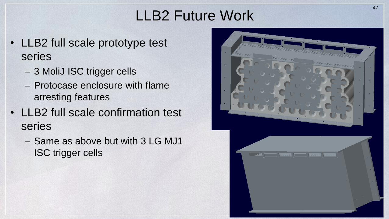
LLB2 Future Work
• LLB2 full scale prototype test
series
– 3 MoliJ ISC trigger cells
– Protocase enclosure with flame
arresting features
• LLB2 full scale confirmation test
series
– Same as above but with 3 LG MJ1
ISC trigger cells
48
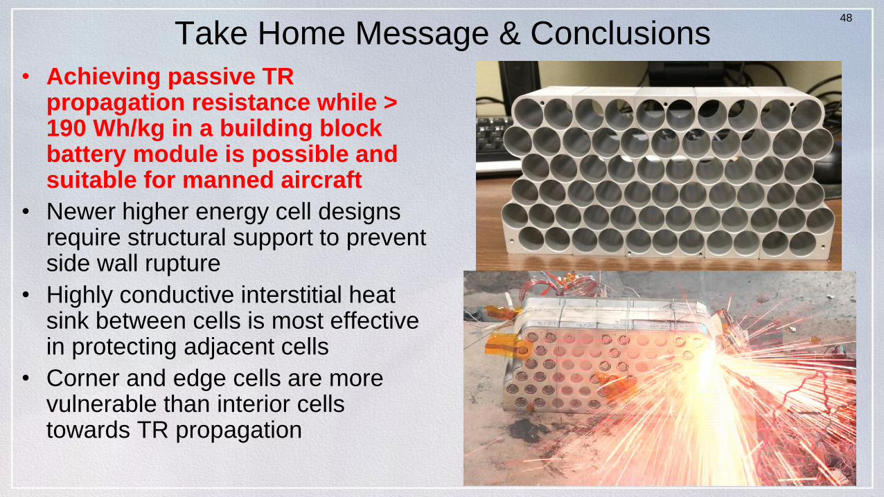
Take Home Message & Conclusions
• Achieving passive TR propagation resistance while > 190 Wh/kg in a building block battery module is possible and suitable for manned aircraft
• Newer higher energy cell designs require structural support to prevent side wall rupture
• Highly conductive interstitial heat sink between cells is most effective in protecting adjacent cells
• Corner and edge cells are more vulnerable than interior cells towards TR propagation
49
Acknowledgements
• TR Severity Reduction Team
– Chris Iannello, NESC Technical Fellow for Electrical
Power, and Deputy, Rob Button
– Steve Rickman, NESC Technical Fellow for Passive
Thermal
– Eric Darcy, Test Lead for EVA Batteries, NASA-JSC
– Sam Russell, Craig Clark, Thomas Viviano, Dereck
Lenoir, and Ann Tripathi/NASA-JSC
– Dan Doughty, Bruce Drolen, Ralph White, Gary
Bayles/NESC Consultants
– Paul Coman, PhD candidate Univ of South Denmark