Embed Size (px)
Citation preview
This paper is included in the Proceedings of the 13th USENIX Symposium on Networked Systems
Design and Implementation (NSDI ’16).March 16–18, 2016 • Santa Clara, CA, USA
ISBN 978-1-931971-29-4
Open access to the Proceedings of the 13th USENIX Symposium on
Networked Systems Design and Implementation (NSDI ’16)
is sponsored by USENIX.
Passive Wi-Fi: Bringing Low Power to Wi-Fi Transmissions
Bryce Kellogg, Vamsi Talla, Shyamnath Gollakota, and Joshua R. Smith, University of Washington
https://www.usenix.org/conference/nsdi16/technical-sessions/presentation/kellogg
USENIX Association 13th USENIX Symposium on Networked Systems Design and Implementation (NSDI ’16) 151
Passive Wi-Fi: Bringing Low Power to Wi-Fi Transmissions
Bryce Kellogg†, Vamsi Talla†, Shyamnath Gollakota and Joshua R. SmithUniversity of Washington
†Co-primary Student Authors
Abstract – Wi-Fi has traditionally been considereda power-consuming communication system and has notbeen widely adopting in the sensor network and IoTspace. We introduce Passive Wi-Fi that demonstrates forthe first time that one can generate 802.11b transmissionsusing backscatter communication, while consuming 3–4 orders of magnitude lower power than existing Wi-Fichipsets. Passive Wi-Fi transmissions can be decodedon any Wi-Fi device including routers, mobile phonesand tablets. Building on this, we also present a net-work stack design that enables passive Wi-Fi transmit-ters to coexist with other devices in the ISM band, with-out incurring the power consumption of carrier sense andmedium access control operations. We build prototypehardware and implement all four 802.11b bit rates onan FPGA platform. Our experimental evaluation showsthat passive Wi-Fi transmissions can be decoded on off-the-shelf smartphones and Wi-Fi chipsets over distancesof 30–100 feet in various line-of- sight and through-the-wall scenarios. Finally, we design a passive Wi-FiIC that shows that 1 and 11 Mbps transmissions con-sume 14.5 and 59.2 µW respectively. This translatesto 10000x lower power than existing Wi-Fi chipsets and1000x lower power than Bluetooth LTE and ZigBee.
1 Introduction
Over the past few years, researchers have explored theconcept of Wi-Fi backscatter [25, 38] that creates an ad-ditional narrowband data stream to ride on top of existingWi-Fi signals. While promising, existing designs eitherachieve very low data rates (100s of bps) at close by dis-tances (2-4 feet) [25] or use custom full-duplex hardwarethat cannot be used with any existing Wi-Fi devices [38].
In this paper, we take a different approach — insteadof backscattering existing Wi-Fi signals to send an ad-ditional data stream, we use backscatter communicationto directly generate Wi-Fi transmissions that can be de-coded on any of the billions of existing devices with a
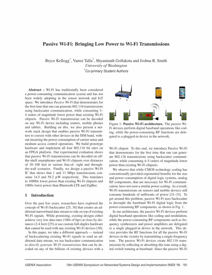
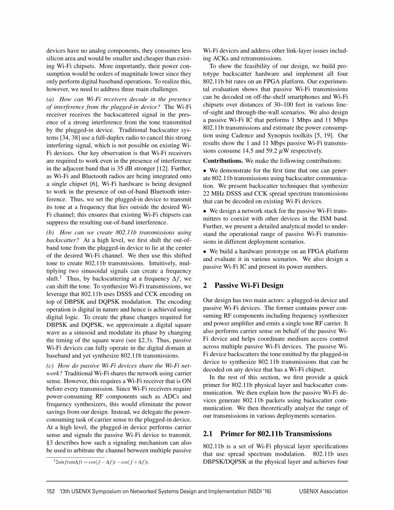
Figure 1: Passive Wi-Fi architecture. The passive Wi-Fi devices perform digital baseband operations like cod-ing, while the power-consuming RF functions are dele-gated to a plugged-in device in the network.
Wi-Fi chipset. To this end, we introduce Passive Wi-Fithat demonstrates for the first time that one can gener-ate 802.11b transmissions using backscatter communi-cation, while consuming 4–5 orders of magnitude lowerpower than existing Wi-Fi chipsets.
We observe that while CMOS technology scaling hasconventionally provided exponential benefits for the sizeand power consumption of digital logic systems, analogRF components, that are necessary for Wi-Fi communi-cation, have not seen a similar power scaling. As a result,Wi-Fi transmissions on sensors and mobile devices stillconsume hundreds of milliwatts of power [31–33]. Toget around this problem, passive Wi-Fi uses backscatterto decouple the baseband Wi-Fi digital logic from thepower-consuming RF components, as shown in Fig. 1.
In our architecture, the passive Wi-Fi devices performdigital baseband operations like coding and modulation,while the power-consuming RF components such as fre-quency synthesizers and power amplifiers are delegatedto a single plugged-in device in the network. This de-vice provides the RF functions for all the passive Wi-Fidevices in the vicinity by transmitting a single-frequencytone. The passive Wi-Fi devices create 802.11b trans-missions by reflecting or absorbing this tone using a dig-ital switch running at baseband. Since the passive Wi-Fi
1
152 13th USENIX Symposium on Networked Systems Design and Implementation (NSDI ’16) USENIX Association
devices have no analog components, they consumes lesssilicon area and would be smaller and cheaper than exist-ing Wi-Fi chipsets. More importantly, their power con-sumption would be orders of magnitude lower since theyonly perform digital baseband operations. To realize this,however, we need to address three main challenges.
(a) How can Wi-Fi receivers decode in the presenceof interference from the plugged-in device? The Wi-Fireceiver receives the backscattered signal in the pres-ence of a strong interference from the tone transmittedby the plugged-in device. Traditional backscatter sys-tems [34, 38] use a full-duplex radio to cancel this stronginterfering signal, which is not possible on existing Wi-Fi devices. Our key observation is that Wi-Fi receiversare required to work even in the presence of interferencein the adjacent band that is 35 dB stronger [12]. Further,as Wi-Fi and Bluetooth radios are being integrated ontoa single chipset [6], Wi-Fi hardware is being designedto work in the presence of out-of-band Bluetooth inter-ference. Thus, we set the plugged-in device to transmitits tone at a frequency that lies outside the desired Wi-Fi channel; this ensures that existing Wi-Fi chipsets cansuppress the resulting out-of-band interference.
(b) How can we create 802.11b transmissions usingbackscatter? At a high level, we first shift the out-of-band tone from the plugged-in device to lie at the centerof the desired Wi-Fi channel. We then use this shiftedtone to create 802.11b transmissions. Intuitively, mul-tiplying two sinusoidal signals can create a frequencyshift.1 Thus, by backscattering at a frequency ∆ f , wecan shift the tone. To synthesize Wi-Fi transmissions, weleverage that 802.11b uses DSSS and CCK encoding ontop of DBPSK and DQPSK modulation. The encodingoperation is digital in nature and hence is achieved usingdigital logic. To create the phase changes required forDBPSK and DQPSK, we approximate a digital squarewave as a sinusoid and modulate its phase by changingthe timing of the square wave (see §2.3). Thus, passiveWi-Fi devices can fully operate in the digital domain atbaseband and yet synthesize 802.11b transmissions.
(c) How do passive Wi-Fi devices share the Wi-Fi net-work? Traditional Wi-Fi shares the network using carriersense. However, this requires a Wi-Fi receiver that is ONbefore every transmission. Since Wi-Fi receivers requirepower-consuming RF components such as ADCs andfrequency synthesizers, this would eliminate the powersavings from our design. Instead, we delegate the power-consuming task of carrier sense to the plugged-in device.At a high level, the plugged-in device performs carriersense and signals the passive Wi-Fi device to transmit.§3 describes how such a signaling mechanism can alsobe used to arbitrate the channel between multiple passive
12sin f tsin∆ f t = cos( f −∆ f )t − cos( f +∆ f )t.
Wi-Fi devices and address other link-layer issues includ-ing ACKs and retransmissions.
To show the feasibility of our design, we build pro-totype backscatter hardware and implement all four802.11b bit rates on an FPGA platform. Our experimen-tal evaluation shows that passive Wi-Fi transmissionscan be decoded on off-the-shelf smartphones and Wi-Fichipsets over distances of 30–100 feet in various line-of-sight and through-the-wall scenarios. We also designa passive Wi-Fi IC that performs 1 Mbps and 11 Mbps802.11b transmissions and estimate the power consump-tion using Cadence and Synopsis toolkits [5, 19]. Ourresults show the 1 and 11 Mbps passive Wi-Fi transmis-sions consume 14.5 and 59.2 µW respectively.
Contributions. We make the following contributions:• We demonstrate for the first time that one can gener-ate 802.11b transmissions using backscatter communica-tion. We present backscatter techniques that synthesize22 MHz DSSS and CCK spread spectrum transmissionsthat can be decoded on existing Wi-Fi devices.• We design a network stack for the passive Wi-Fi trans-mitters to coexist with other devices in the ISM band.Further, we present a detailed analytical model to under-stand the operational range of passive Wi-Fi transmis-sions in different deployment scenarios.• We build a hardware prototype on an FPGA platformand evaluate it in various scenarios. We also design apassive Wi-Fi IC and present its power numbers.
2 Passive Wi-Fi Design
Our design has two main actors: a plugged-in device andpassive Wi-Fi devices. The former contains power con-suming RF components including frequency synthesizerand power amplifier and emits a single tone RF carrier. Italso performs carrier sense on behalf of the passive Wi-Fi device and helps coordinate medium access controlacross multiple passive Wi-Fi devices. The passive Wi-Fi device backscatters the tone emitted by the plugged-indevice to synthesize 802.11b transmissions that can bedecoded on any device that has a Wi-Fi chipset.
In the rest of this section, we first provide a quickprimer for 802.11b physical layer and backscatter com-munication. We then explain how the passive Wi-Fi de-vices generate 802.11b packets using backscatter com-munication. We then theoretically analyze the range ofour transmissions in various deployments scenarios.
2.1 Primer for 802.11b Transmissions802.11b is a set of Wi-Fi physical layer specificationsthat use spread spectrum modulation. 802.11b usesDBPSK/DQPSK at the physical layer and achieves four
2
USENIX Association 13th USENIX Symposium on Networked Systems Design and Implementation (NSDI ’16) 153
-40 -30 -20 -10 0 10 20 30 40
Am
plit
ud
e2
Frequency (MHz)
Am
plit
ud
e2
∆ f ∆ f
fwififwifi - 2∆f
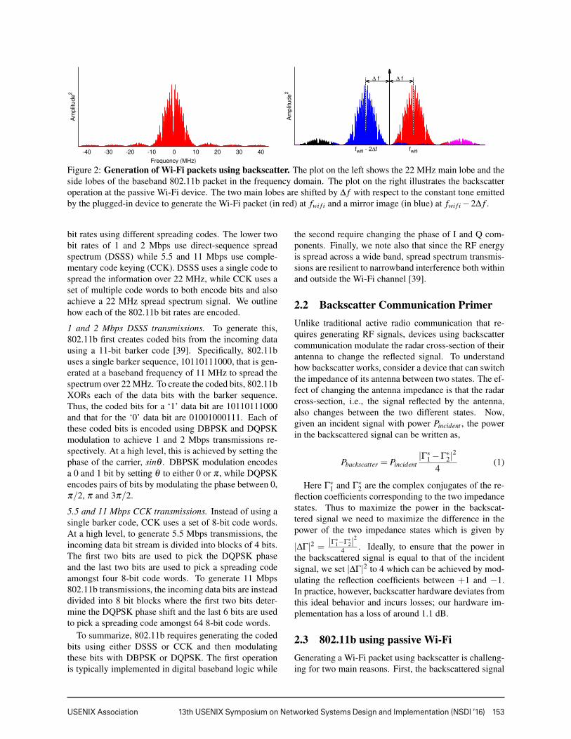
Figure 2: Generation of Wi-Fi packets using backscatter. The plot on the left shows the 22 MHz main lobe and theside lobes of the baseband 802.11b packet in the frequency domain. The plot on the right illustrates the backscatteroperation at the passive Wi-Fi device. The two main lobes are shifted by ∆ f with respect to the constant tone emittedby the plugged-in device to generate the Wi-Fi packet (in red) at fwi f i and a mirror image (in blue) at fwi f i −2∆ f .
bit rates using different spreading codes. The lower twobit rates of 1 and 2 Mbps use direct-sequence spreadspectrum (DSSS) while 5.5 and 11 Mbps use comple-mentary code keying (CCK). DSSS uses a single code tospread the information over 22 MHz, while CCK uses aset of multiple code words to both encode bits and alsoachieve a 22 MHz spread spectrum signal. We outlinehow each of the 802.11b bit rates are encoded.
1 and 2 Mbps DSSS transmissions. To generate this,802.11b first creates coded bits from the incoming datausing a 11-bit barker code [39]. Specifically, 802.11buses a single barker sequence, 10110111000, that is gen-erated at a baseband frequency of 11 MHz to spread thespectrum over 22 MHz. To create the coded bits, 802.11bXORs each of the data bits with the barker sequence.Thus, the coded bits for a ‘1’ data bit are 10110111000and that for the ‘0’ data bit are 01001000111. Each ofthese coded bits is encoded using DBPSK and DQPSKmodulation to achieve 1 and 2 Mbps transmissions re-spectively. At a high level, this is achieved by setting thephase of the carrier, sinθ . DBPSK modulation encodesa 0 and 1 bit by setting θ to either 0 or π , while DQPSKencodes pairs of bits by modulating the phase between 0,π/2, π and 3π/2.
5.5 and 11 Mbps CCK transmissions. Instead of using asingle barker code, CCK uses a set of 8-bit code words.At a high level, to generate 5.5 Mbps transmissions, theincoming data bit stream is divided into blocks of 4 bits.The first two bits are used to pick the DQPSK phaseand the last two bits are used to pick a spreading codeamongst four 8-bit code words. To generate 11 Mbps802.11b transmissions, the incoming data bits are insteaddivided into 8 bit blocks where the first two bits deter-mine the DQPSK phase shift and the last 6 bits are usedto pick a spreading code amongst 64 8-bit code words.
To summarize, 802.11b requires generating the codedbits using either DSSS or CCK and then modulatingthese bits with DBPSK or DQPSK. The first operationis typically implemented in digital baseband logic while
the second require changing the phase of I and Q com-ponents. Finally, we note also that since the RF energyis spread across a wide band, spread spectrum transmis-sions are resilient to narrowband interference both withinand outside the Wi-Fi channel [39].
2.2 Backscatter Communication PrimerUnlike traditional active radio communication that re-quires generating RF signals, devices using backscattercommunication modulate the radar cross-section of theirantenna to change the reflected signal. To understandhow backscatter works, consider a device that can switchthe impedance of its antenna between two states. The ef-fect of changing the antenna impedance is that the radarcross-section, i.e., the signal reflected by the antenna,also changes between the two different states. Now,given an incident signal with power Pincident , the powerin the backscattered signal can be written as,
Pbackscatter = Pincident|Γ∗
1 −Γ∗2|
2
4(1)
Here Γ∗1 and Γ∗
2 are the complex conjugates of the re-flection coefficients corresponding to the two impedancestates. Thus to maximize the power in the backscat-tered signal we need to maximize the difference in thepower of the two impedance states which is given by
|∆Γ|2 =|Γ∗
1−Γ∗2|
2
4 . Ideally, to ensure that the power inthe backscattered signal is equal to that of the incidentsignal, we set |∆Γ|2 to 4 which can be achieved by mod-ulating the reflection coefficients between +1 and −1.In practice, however, backscatter hardware deviates fromthis ideal behavior and incurs losses; our hardware im-plementation has a loss of around 1.1 dB.
2.3 802.11b using passive Wi-FiGenerating a Wi-Fi packet using backscatter is challeng-ing for two main reasons. First, the backscattered signal
3
154 13th USENIX Symposium on Networked Systems Design and Implementation (NSDI ’16) USENIX Association
is much weaker than the tone transmitted by the plugged-in device. A Wi-Fi receiver would suffer significant in-band interference from this tone preventing it from de-coding. Second, the passive Wi-Fi device has a singledigital switch that toggles between two impedance states,resulting in a binary signal. It is unclear how one maygenerate Wi-Fi transmissions using such a binary system.
We outline how to address these challenges. We firstdescribe the signal transmissions from the plugged-in de-vice and then the operations at the passive Wi-Fi devicethat allow us to synthesize 802.11b transmissions.
Transmissions at the plugged-in device. It transmits atone outside the desired Wi-Fi channel. Our key intuitionis that Wi-Fi receivers are designed to function in thepresence of out-of-band interference: 802.11b receiversare required to ensure that the sensitivity is reduced byno more than 6 dB in the presence of interference in theadjacent band that is 35 dB greater than the in-band sig-nal [12]. Further, as Wi-Fi and Bluetooth radios are be-ing integrated onto the same chipset [6], Wi-Fi frontendsare being designed to function in the presence of out-of-band interference from Bluetooth devices. Since the tonefrom the plugged-in device is narrower in bandwidth thanBluetooth, this would further help suppress the tone if itis outside the desired Wi-Fi channel.
We note however that excessive out-of-band interfer-ence, which occurs when the Wi-Fi receiver is right nextto the plugged-in device, can saturate and/or compressthe RF front end resulting in significant degradation ofWi-Fi performance. This is called the input 1 dB com-pression point which is around 0 dBm for commercialWi-Fi devices [13]. Passive Wi-Fi inherently avoids thisissue by ensuring that the Wi-Fi receiver (e.g., smart-phone or router) is not next to the plugged-in device.
Backscatter operations at passive Wi-Fi devices. Ata high level, the passive Wi-Fi operations can be de-scribed as first shifting the out-of-band tone transmit-ted from the plugged-in device to lie at the center ofthe desired Wi-Fi channel. We then use this shiftedtone to create 802.11b transmissions. To do this, weleverage three key facts: (1) From basic trigonometry,2sin f tsin∆ f t = cos( f −∆ f )t−cos( f +∆ f )t. Thus, mul-tiplying two sinusoidal signals can create a frequencyshift. (2) Modulating the radar cross section of an an-tenna effectively multiplies the incoming signal by themodulated signal. Thus, modulating the antenna at a fre-quency ∆ f would create a frequency shift in the incom-ing signal. (3) All bit rates in 802.11b are differentiallyphase modulated using DBPSK or DQPSK.
Step 1. Shifting the tone from the plugged-in device usingbackscatter. Say the plugged-in device sends the tonesin2π( fwi f i − ∆ f )t outside the Wi-Fi channel. PassiveWi-Fi devices use a square wave at a frequency of ∆ f to
shift the tone to the center of the Wi-Fi channel. FromFourier analysis, a square wave can be written as,
Square(∆ f t) =4π
∞
∑n=1,3,5,..
1n
sin(2πn∆ f t)
Here the first harmonic is a sinusoidal signal at the de-sired frequency ∆ f . Note that the power in each ofthese harmonic scales as 1
n2 . So the third and the fifthharmonic are around 9.5 dB and 14 dB lower than thefirst harmonic. Thus, we can approximate a squarewave as just the sinusoidal signal, 4
π sin(2π∆ f t). Sincemodulating the radar cross section of an antenna effec-tively multiplies the incoming signal by the modulatedsignal, the backscatter signal can be approximated assin2π( fwi f i −∆ f )tsin2π∆ f t. So we have used backscat-ter to effectively creates two tones, one centered at fwi f iand the other at fwi f i −2∆ f ; the first tone is at the centerof the desired Wi-Fi channel.
Step 2. Synthesizing 802.11b transmissions usingbackscatter. Now that we have a tone centered at the Wi-Fi channel, the next step is to create 802.11b transmis-sions using backscatter. 802.11b uses DSSS and CCKencoding which are both digital operations and hence canbe performed using digital logic at the passive Wi-Fi de-vice. So the question that remains is: how do we generateDBPSK and DQPSK using just a square wave created ata frequency ∆ f by the backscatter switch?
Passive Wi-Fi does this by noting that DBPSK andDQPSK use a sine wave with four distinct phases:0,π/2,π,3π/2. Since the square wave generated by ourdigital switch can be approximated as a sine wave, wecan generate the required four phases by changing thetiming of our square wave. Specifically, shifting thesquare wave by half of a symbol time, effectively createsa phase change of π . Phase changes of π/2 and 3π/2 canbe achieved by shifting the square wave by one-fourthand three-fourth of a symbol time. Thus, passive Wi-Fidevices can fully operate in the digital domain while runat a baseband frequency of a few tens of MHz and syn-thesize 802.11b transmissions using backscatter.
We note the following properties of our design.• In addition to creating a 802.11b transmission centeredat fwi f i, as shown in Fig. 2, our backscatter mechanismalso creates a mirror copy centered at fwi f i −2∆ f on theother side of the tone. Thus, we use twice the bandwidthof a traditional 802.11b transmission. This is the tradeoffwe make to achieve orders of magnitude lower powerconsumption. We note that such a tradeoff is common in802.11n systems which use channel bonding of adjacentWi-Fi channels to double the throughput.• 802.11b transmissions have side lobes (Fig. 2); theside lobes of the mirror copy creates interference for thedesired Wi-Fi signal. We plot the signal to interference
4
USENIX Association 13th USENIX Symposium on Networked Systems Design and Implementation (NSDI ’16) 155
5
10
15
20
25
10 12 14 16 18 20 22
SIR
(dB
)
∆ f (MHz)
1 Mbps2 Mbps
5.5 Mbps11 Mbps
0
1
2
3
4
5
10 12 14 16 18 20 22
Sensitiv
ity L
oss (
dB
)
∆ f (MHz)
1 Mbps2 Mbps
5.5 Mbps11 Mbps
(a) Signal to Interference ratio (b) Sensitivity Loss
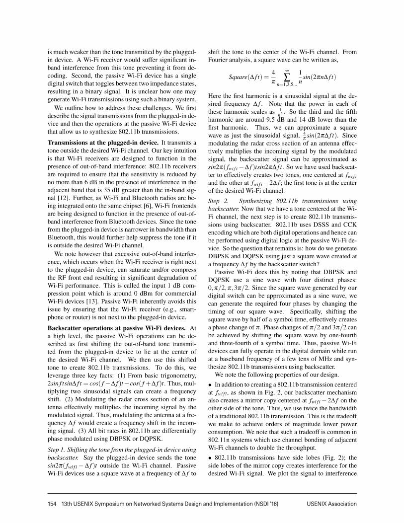
Figure 3: SIR and loss in receiver sensitivity. The plotshows the effect of different ∆ f ’s on the quality and thesensitivity of the synthesized Wi-Fi packets.
ratio for different frequency shifts, ∆ f , at the passive Wi-Fi device. Fig. 3(a) plots the results for all four 802.11bbit rates and shows that the interference from the sidelobes of the mirror copy reduces as ∆ f increases. Thisis because, as ∆ f increases, the mirror copies are furtherseparated in frequency, resulting in lower interference.• An effect of this interference, however, is that it addsadditional noise to the Wi-Fi signal, reducing the noisesensitivity at which each of the 802.11b bit rates can bedecoded. Fig. 3(b) shows the loss in sensitivity for thefour 802.11b bit rates, as a function of the frequency off-set, ∆ f . The plots show that the sensitivity loss is slightlylarger for higher 802.11b bit rates. This is because higherbit rates require a cleaner signal to successfully be de-coded. Our system sets ∆ f to 12.375 MHz, where thesensitivity loss is less than 2 dB across all 802.11b bitrates. This also ensures that the passive Wi-Fi transmis-sions only occupy two adjacent Wi-Fi channels. Notethat Wi-Fi applies filters to remove the interfering sidelobes. Our implementation however does not do this.
2.4 Analyzing Passive Wi-Fi’s RangeIn passive Wi-Fi, the communication range depends ontwo parameters: the distance between the plugged-in de-vice and the passive Wi-Fi transmitter and the distancebetween the passive Wi-Fi transmitter and the Wi-Fi re-ceiver. Specifically, the signal strength at the receiver, Pr,can be modeled using Friis path loss [34] as follows,
Pr =
(PtGt
4πd21
)(λ 2G2
passive
4π|∆Γ|2
4αwi f i
)(1
4πd22
λ 2Gr
4π
)
This equation has three key parts: the term in first paren-thesis models signal propagation from the plugged-in de-vice, with an output power Pt and an antenna gain Gt , toa passive Wi-Fi transmitter at a distance d1 away. Thethird term, similarly, models the signal propagation fromthe passive Wi-Fi transmitter to a Wi-Fi receiver with anantenna gain Gr and at a distance d2 away. Here, λ isthe wavelength of the RF signal been transmitted. Fi-nally, the middle parenthesis models the fraction of inci-
d1 d2
-80
-70
-60
-50
0 5 10 15 20 25 30 35 40 45
Sig
nal S
trength
(dB
m)
Distance d1 (ft)
d1 + d2 = 45 ft
midpoint
-100
-80
-60
-40
-20
0 10 20 30 40
Mid
-poin
t sig
nal
str
ength
(dB
m)
Distance d1 + d2 (ft)
Pt = 10 dBmPt = 20 dBmPt = 30 dBm
Figure 4: Passive Wi-Fi’s analytical received signalstrength. The passive Wi-Fi device moves along the lineconnecting the Wi-Fi router and plugged-in device.
-100
-90
-80
-70
-60
-50
-40
-30
0 20 40 60 80 100
Sig
nal S
trength
(dB
m)
Distance between Passive Wi-Fi device and smartphone (ft)
Passive Wi-Fi / Plugged in device separation: 5 ft15 ft25 ft
Figure 5: Signal strength versus distance between pas-sive Wi-Fi transmitter and Wi-Fi receiver.
dent signal from the plugged-in device that is backscat-tered by a passive Wi-Fi transmitter with an antenna gainGpassive. |∆Γ|2 is the backscatter coefficient which is ameasure of the efficiency with which passive Wi-Fi cangenerate backscatter signals. As described in §2.2, this is1.1 dB in our hardware. Finally, αwi f i models the loss inenergy due to synthesis of Wi-Fi signals using backscat-ter. This is around 4.4 dB and includes half the powerlost in the mirror copy generated by backscatter and thelosses due to the side lobes as described in §2.3.
To gain a better intuition, consider the scenario inFig. 4 where we place the plugged-in device and theWi-Fi receiver separated by 45 feet. We move the pas-sive Wi-Fi transmitter between these devices, along theline connecting them. We set Pt , Gt , Gr and Gpassive to30 dBm, 6 dBi, 0 dBi, and 2 dBi respectively. Fig. 4shows the received signal strength, Pr, as we move thepassive Wi-Fi transmitter between the plugged-in deviceand the Wi-Fi receiver. The plots show two key points.
(1) The received signal increases as the passive Wi-Fitransmitter gets close to either the Wi-Fi receiver or theplugged-in device. This is because, maximizing the sig-nal strength requires minimizing the product d1d2, whichis achieved either by reducing the distance d1 or d2.
(2) The mid-point between the plugged-in device andWi-Fi receiver has the lowest strength. Fig. 4 showsthis mid-point signal strength, as we change the distancebetween the plugged-in device and Wi-Fi receiver. Theplot shows that this decreases with distance between theplugged-in device and the Wi-Fi receiver. As expected,it increases with plugged-in device’s transmit power (Pt ).
5
156 13th USENIX Symposium on Networked Systems Design and Implementation (NSDI ’16) USENIX Association
(a) 30 ft Separation (b) 50 ft Separation (c) 55 ft Separation (d) 60 ft Separation
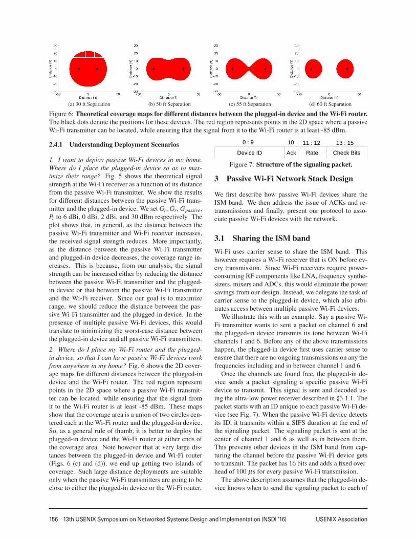
Figure 6: Theoretical coverage maps for different distances between the plugged-in device and the Wi-Fi router.The black dots denote the positions for these devices. The red region represents points in the 2D space where a passiveWi-Fi transmitter can be located, while ensuring that the signal from it to the Wi-Fi router is at least -85 dBm.
2.4.1 Understanding Deployment Scenarios
1. I want to deploy passive Wi-Fi devices in my home.Where do I place the plugged-in device so as to max-imize their range? Fig. 5 shows the theoretical signalstrength at the Wi-Fi receiver as a function of its distancefrom the passive Wi-Fi transmitter. We show the resultsfor different distances between the passive Wi-Fi trans-mitter and the plugged-in device. We set Gt , Gr, Gpassive,Pt to 6 dBi, 0 dBi, 2 dBi, and 30 dBm respectively. Theplot shows that, in general, as the distance between thepassive Wi-Fi transmitter and Wi-Fi receiver increases,the received signal strength reduces. More importantly,as the distance between the passive Wi-Fi transmitterand plugged-in device decreases, the coverage range in-creases. This is because, from our analysis, the signalstrength can be increased either by reducing the distancebetween the passive Wi-Fi transmitter and the plugged-in device or that between the passive Wi-Fi transmitterand the Wi-Fi receiver. Since our goal is to maximizerange, we should reduce the distance between the pas-sive Wi-Fi transmitter and the plugged-in device. In thepresence of multiple passive Wi-Fi devices, this wouldtranslate to minimizing the worst-case distance betweenthe plugged-in device and all passive Wi-Fi transmitters.
2. Where do I place my Wi-Fi router and the plugged-in device, so that I can have passive Wi-Fi devices workfrom anywhere in my home? Fig. 6 shows the 2D cover-age maps for different distances between the plugged-indevice and the Wi-Fi router. The red region representpoints in the 2D space where a passive Wi-Fi transmit-ter can be located, while ensuring that the signal fromit to the Wi-Fi router is at least -85 dBm. These mapsshow that the coverage area is a union of two circles cen-tered each at the Wi-Fi router and the plugged-in device.So, as a general rule of thumb, it is better to deploy theplugged-in device and the Wi-Fi router at either ends ofthe coverage area. Note however that at very large dis-tances between the plugged-in device and Wi-Fi router(Figs. 6 (c) and (d)), we end up getting two islands ofcoverage. Such large distance deployments are suitableonly when the passive Wi-Fi transmitters are going to beclose to either the plugged-in device or the Wi-Fi router.
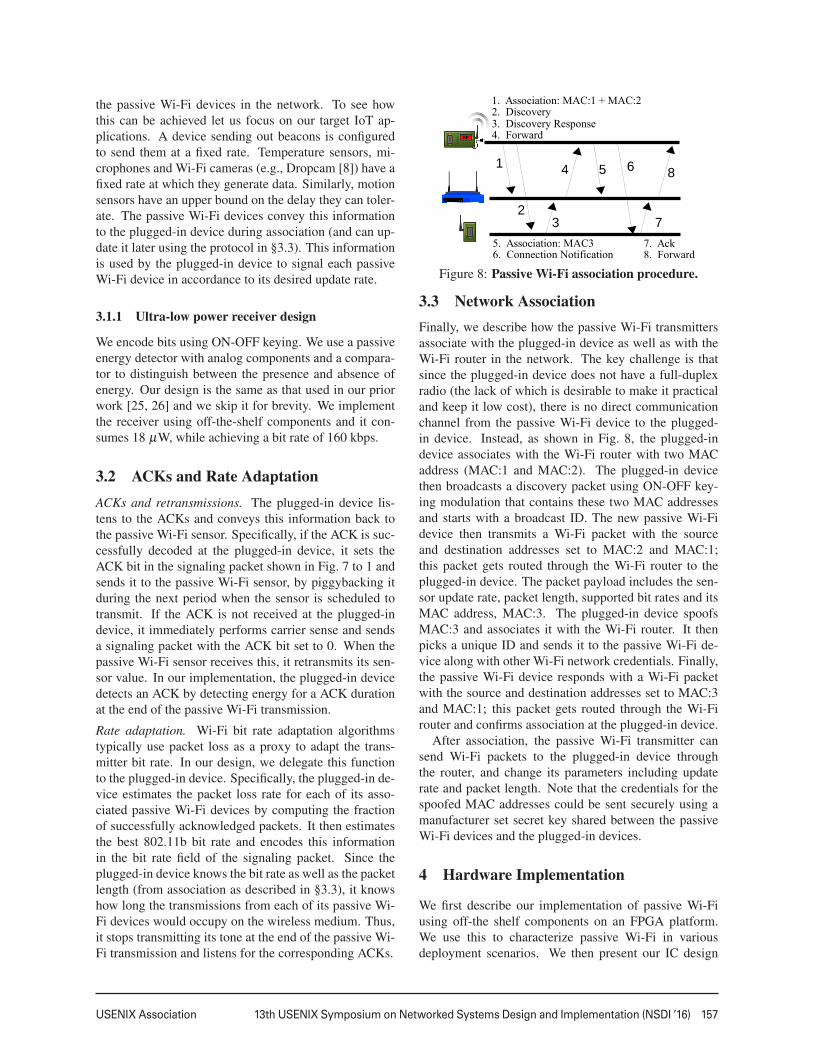
Device ID Ack Rate Check Bits
0 : 9 10 11 : 12 13 : 15
Figure 7: Structure of the signaling packet.
3 Passive Wi-Fi Network Stack Design
We first describe how passive Wi-Fi devices share theISM band. We then address the issue of ACKs and re-transmissions and finally, present our protocol to asso-ciate passive Wi-Fi devices with the network.
3.1 Sharing the ISM bandWi-Fi uses carrier sense to share the ISM band. Thishowever requires a Wi-Fi receiver that is ON before ev-ery transmission. Since Wi-Fi receivers require power-consuming RF components like LNA, frequency synthe-sizers, mixers and ADCs, this would eliminate the powersavings from our design. Instead, we delegate the task ofcarrier sense to the plugged-in device, which also arbi-trates access between multiple passive Wi-Fi devices.
We illustrate this with an example. Say a passive Wi-Fi transmitter wants to sent a packet on channel 6 andthe plugged-in device transmits its tone between Wi-Fichannels 1 and 6. Before any of the above transmissionshappen, the plugged-in device first uses carrier sense toensure that there are no ongoing transmissions on any thefrequencies including and in between channel 1 and 6.
Once the channels are found free, the plugged-in de-vice sends a packet signaling a specific passive Wi-Fidevice to transmit. This signal is sent and decoded us-ing the ultra-low power receiver described in §3.1.1. Thepacket starts with an ID unique to each passive Wi-Fi de-vice (see Fig. 7). When the passive Wi-Fi device detectsits ID, it transmits within a SIFS duration at the end ofthe signaling packet. The signaling packet is sent at thecenter of channel 1 and 6 as well as in between them.This prevents other devices in the ISM band from cap-turing the channel before the passive Wi-Fi device getsto transmit. The packet has 16 bits and adds a fixed over-head of 100 µs for every passive Wi-Fi transmission.
The above description assumes that the plugged-in de-vice knows when to send the signaling packet to each of
6
USENIX Association 13th USENIX Symposium on Networked Systems Design and Implementation (NSDI ’16) 157
the passive Wi-Fi devices in the network. To see howthis can be achieved let us focus on our target IoT ap-plications. A device sending out beacons is configuredto send them at a fixed rate. Temperature sensors, mi-crophones and Wi-Fi cameras (e.g., Dropcam [8]) have afixed rate at which they generate data. Similarly, motionsensors have an upper bound on the delay they can toler-ate. The passive Wi-Fi devices convey this informationto the plugged-in device during association (and can up-date it later using the protocol in §3.3). This informationis used by the plugged-in device to signal each passiveWi-Fi device in accordance to its desired update rate.
3.1.1 Ultra-low power receiver design
We encode bits using ON-OFF keying. We use a passiveenergy detector with analog components and a compara-tor to distinguish between the presence and absence ofenergy. Our design is the same as that used in our priorwork [25, 26] and we skip it for brevity. We implementthe receiver using off-the-shelf components and it con-sumes 18 µW, while achieving a bit rate of 160 kbps.
3.2 ACKs and Rate AdaptationACKs and retransmissions. The plugged-in device lis-tens to the ACKs and conveys this information back tothe passive Wi-Fi sensor. Specifically, if the ACK is suc-cessfully decoded at the plugged-in device, it sets theACK bit in the signaling packet shown in Fig. 7 to 1 andsends it to the passive Wi-Fi sensor, by piggybacking itduring the next period when the sensor is scheduled totransmit. If the ACK is not received at the plugged-indevice, it immediately performs carrier sense and sendsa signaling packet with the ACK bit set to 0. When thepassive Wi-Fi sensor receives this, it retransmits its sen-sor value. In our implementation, the plugged-in devicedetects an ACK by detecting energy for a ACK durationat the end of the passive Wi-Fi transmission.
Rate adaptation. Wi-Fi bit rate adaptation algorithmstypically use packet loss as a proxy to adapt the trans-mitter bit rate. In our design, we delegate this functionto the plugged-in device. Specifically, the plugged-in de-vice estimates the packet loss rate for each of its asso-ciated passive Wi-Fi devices by computing the fractionof successfully acknowledged packets. It then estimatesthe best 802.11b bit rate and encodes this informationin the bit rate field of the signaling packet. Since theplugged-in device knows the bit rate as well as the packetlength (from association as described in §3.3), it knowshow long the transmissions from each of its passive Wi-Fi devices would occupy on the wireless medium. Thus,it stops transmitting its tone at the end of the passive Wi-Fi transmission and listens for the corresponding ACKs.
1. Association: MAC:1 + MAC:2
5. Association: MAC36. Connection Notification
2. Discovery3. Discovery Response
1
2
3
4 5 6
7
8
4. Forward
7. Ack8. Forward
Figure 8: Passive Wi-Fi association procedure.
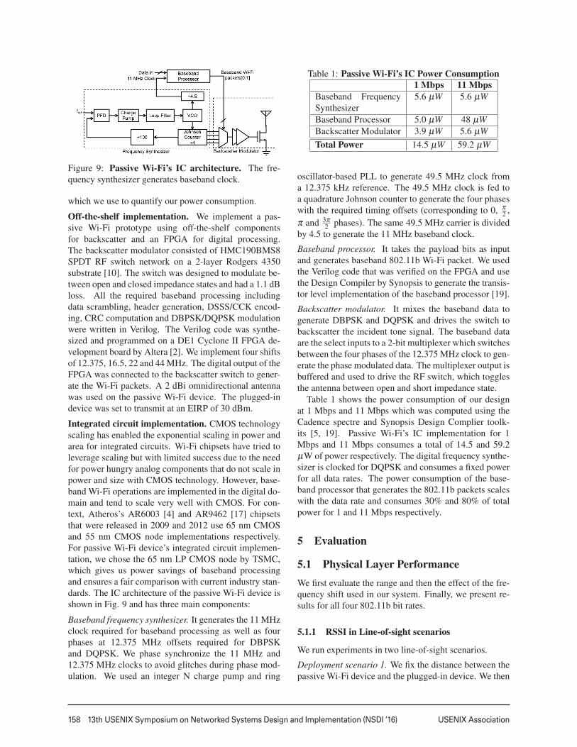
3.3 Network AssociationFinally, we describe how the passive Wi-Fi transmittersassociate with the plugged-in device as well as with theWi-Fi router in the network. The key challenge is thatsince the plugged-in device does not have a full-duplexradio (the lack of which is desirable to make it practicaland keep it low cost), there is no direct communicationchannel from the passive Wi-Fi device to the plugged-in device. Instead, as shown in Fig. 8, the plugged-indevice associates with the Wi-Fi router with two MACaddress (MAC:1 and MAC:2). The plugged-in devicethen broadcasts a discovery packet using ON-OFF key-ing modulation that contains these two MAC addressesand starts with a broadcast ID. The new passive Wi-Fidevice then transmits a Wi-Fi packet with the sourceand destination addresses set to MAC:2 and MAC:1;this packet gets routed through the Wi-Fi router to theplugged-in device. The packet payload includes the sen-sor update rate, packet length, supported bit rates and itsMAC address, MAC:3. The plugged-in device spoofsMAC:3 and associates it with the Wi-Fi router. It thenpicks a unique ID and sends it to the passive Wi-Fi de-vice along with other Wi-Fi network credentials. Finally,the passive Wi-Fi device responds with a Wi-Fi packetwith the source and destination addresses set to MAC:3and MAC:1; this packet gets routed through the Wi-Firouter and confirms association at the plugged-in device.
After association, the passive Wi-Fi transmitter cansend Wi-Fi packets to the plugged-in device throughthe router, and change its parameters including updaterate and packet length. Note that the credentials for thespoofed MAC addresses could be sent securely using amanufacturer set secret key shared between the passiveWi-Fi devices and the plugged-in devices.
4 Hardware Implementation
We first describe our implementation of passive Wi-Fiusing off-the shelf components on an FPGA platform.We use this to characterize passive Wi-Fi in variousdeployment scenarios. We then present our IC design
7
158 13th USENIX Symposium on Networked Systems Design and Implementation (NSDI ’16) USENIX Association
Figure 9: Passive Wi-Fi’s IC architecture. The fre-quency synthesizer generates baseband clock.
which we use to quantify our power consumption.
Off-the-shelf implementation. We implement a pas-sive Wi-Fi prototype using off-the-shelf componentsfor backscatter and an FPGA for digital processing.The backscatter modulator consisted of HMC190BMS8SPDT RF switch network on a 2-layer Rodgers 4350substrate [10]. The switch was designed to modulate be-tween open and closed impedance states and had a 1.1 dBloss. All the required baseband processing includingdata scrambling, header generation, DSSS/CCK encod-ing, CRC computation and DBPSK/DQPSK modulationwere written in Verilog. The Verilog code was synthe-sized and programmed on a DE1 Cyclone II FPGA de-velopment board by Altera [2]. We implement four shiftsof 12.375, 16.5, 22 and 44 MHz. The digital output of theFPGA was connected to the backscatter switch to gener-ate the Wi-Fi packets. A 2 dBi omnidirectional antennawas used on the passive Wi-Fi device. The plugged-indevice was set to transmit at an EIRP of 30 dBm.
Integrated circuit implementation. CMOS technologyscaling has enabled the exponential scaling in power andarea for integrated circuits. Wi-Fi chipsets have tried toleverage scaling but with limited success due to the needfor power hungry analog components that do not scale inpower and size with CMOS technology. However, base-band Wi-Fi operations are implemented in the digital do-main and tend to scale very well with CMOS. For con-text, Atheros’s AR6003 [4] and AR9462 [17] chipsetsthat were released in 2009 and 2012 use 65 nm CMOSand 55 nm CMOS node implementations respectively.For passive Wi-Fi device’s integrated circuit implemen-tation, we chose the 65 nm LP CMOS node by TSMC,which gives us power savings of baseband processingand ensures a fair comparison with current industry stan-dards. The IC architecture of the passive Wi-Fi device isshown in Fig. 9 and has three main components:
Baseband frequency synthesizer. It generates the 11 MHzclock required for baseband processing as well as fourphases at 12.375 MHz offsets required for DBPSKand DQPSK. We phase synchronize the 11 MHz and12.375 MHz clocks to avoid glitches during phase mod-ulation. We used an integer N charge pump and ring
Table 1: Passive Wi-Fi’s IC Power Consumption1 Mbps 11 Mbps
Baseband FrequencySynthesizer
5.6 µW 5.6 µW
Baseband Processor 5.0 µW 48 µWBackscatter Modulator 3.9 µW 5.6 µWTotal Power 14.5 µW 59.2 µW
oscillator-based PLL to generate 49.5 MHz clock froma 12.375 kHz reference. The 49.5 MHz clock is fed toa quadrature Johnson counter to generate the four phaseswith the required timing offsets (corresponding to 0, π
2 ,π and 3π
2 phases). The same 49.5 MHz carrier is dividedby 4.5 to generate the 11 MHz baseband clock.
Baseband processor. It takes the payload bits as inputand generates baseband 802.11b Wi-Fi packet. We usedthe Verilog code that was verified on the FPGA and usethe Design Compiler by Synopsis to generate the transis-tor level implementation of the baseband processor [19].
Backscatter modulator. It mixes the baseband data togenerate DBPSK and DQPSK and drives the switch tobackscatter the incident tone signal. The baseband dataare the select inputs to a 2-bit multiplexer which switchesbetween the four phases of the 12.375 MHz clock to gen-erate the phase modulated data. The multiplexer output isbuffered and used to drive the RF switch, which togglesthe antenna between open and short impedance state.
Table 1 shows the power consumption of our designat 1 Mbps and 11 Mbps which was computed using theCadence spectre and Synopsis Design Complier toolk-its [5, 19]. Passive Wi-Fi’s IC implementation for 1Mbps and 11 Mbps consumes a total of 14.5 and 59.2µW of power respectively. The digital frequency synthe-sizer is clocked for DQPSK and consumes a fixed powerfor all data rates. The power consumption of the base-band processor that generates the 802.11b packets scaleswith the data rate and consumes 30% and 80% of totalpower for 1 and 11 Mbps respectively.
5 Evaluation
5.1 Physical Layer PerformanceWe first evaluate the range and then the effect of the fre-quency shift used in our system. Finally, we present re-sults for all four 802.11b bit rates.
5.1.1 RSSI in Line-of-sight scenarios
We run experiments in two line-of-sight scenarios.
Deployment scenario 1. We fix the distance between thepassive Wi-Fi device and the plugged-in device. We then
8
USENIX Association 13th USENIX Symposium on Networked Systems Design and Implementation (NSDI ’16) 159
-70
-65
-60
-55
-50
-45
-40
-35
0 10 20 30 40 50 60 70 80 90 100
RS
SI
Distance between Passive Wi-Fi device and smartphone (in ft)
Passive Wi-Fi / Plugged in device separation: 3 ft6 ft
12 ft
Figure 10: RSSI in deployment scenario 1. We movethe phone away from the passive Wi-Fi device.
-60
-55
-50
-45
RS
SI
d1 + d2 = 18 ft
-65
-60
-55
-50
RS
SI
d1 + d2 = 24 ft
-65
-60
-55
-50
0 5 10 15 20 25 30
RS
SI
Distance d1 (in ft)
d1 + d2 = 30 ft
Figure 11: RSSI in deployment scenario 2. d1 (d2) isthe distance between the passive Wi-Fi and plugged-indevice (Wi-Fi receiver). The passive Wi-Fi device movesalone the line joining the other two devices.
move the Wi-Fi receiver away from the passive Wi-Fidevice and measure the RSSI of the passive Wi-Fi trans-missions as seen by the receiver. We run the experimentsin the CSE atrium where the maximum distance possiblewhen the passive Wi-Fi device and Wi-Fi receiver wereplaced on either end was around 100 feet. In our ex-periments, we set the passive Wi-Fi device to generate802.11b beacon packets at 1 Mbps. These packets have apayload of 68 bytes where the SSID is set to WiLab_0000and are transmitted every 15 ms. We set the plugged-indevice to transmit its tone 12.375 MHz from the centerof Wi-Fi channel 1 between channel 1 and 6. We usean HTC One (M7) phone as our Wi-Fi receiver. Sincethe passive Wi-Fi device is transmitting Wi-Fi beacons,it appears as a Wi-Fi AP at the smartphone. To measurethe RSSI values of these packets, we use a third partyAndroid app called Wifi Analyzer [3] that provides theRSSI value as shown in Fig. 12.
In each experiment, we hold the smartphone in ourhand and measure the reported RSSI values as we walkaway from the passive Wi-Fi device. The measurementsare taken at increments of 4 feet. Fig. 10 plots the re-sults for three different values of the distance betweenthe passive Wi-Fi transmitter and the plugged-in device.The x-axis plots the distance between the passive Wi-Fitransmitter and the Wi-Fi receiver while the y-axis plotsthe reported RSSI values. The plots show that as ex-pected, the RSSI values reduce as the phone moves away
Figure 12: Snapshot of the Wi-Fi analyzer app.WiLab_0000 corresponds to passive Wi-Fi beacons.
-75
-70
-65
-60
-55
-50
-45
0 5 10 15 20 25 30 35 40 45
RS
SI
Distance between Passive Wi-Fi device and smartphone (in ft)
Passive Wi-Fi device / plugged-in device separation: 1 ft6 ft
Figure 13: RSSI in deployment scenario 1 in the pres-ence of walls. The brown blocks show the wall positions.
from the passive Wi-Fi device. Further, as predicted byour analysis in §2.4, the range of our passive Wi-Fi trans-missions reduce with the distance between the passiveWi-Fi transmitter and the plugged-in device. When theseparation between the passive Wi-Fi transmitter and theplugged-in device is 3 or 6 feet, the range of the passiveWi-Fi transmissions spans the entire length of the CSEatrium. The range is around 55 feet when this separationis 12 feet. This reduced range is due to a combination ofmultipath and a weak backscatter signal.
Deployment scenario 2. Next we place the plugged-indevice and the Wi-Fi receiver at a distance d1 + d2. Wemove the passive Wi-Fi transmitter along the line con-necting these two devices. As above the passive Wi-Fitransmitter is set to generate 802.11b beacon packets at1 Mbps and the plugged-in device transmits its tone at12.375 MHz from the center of Wi-Fi channel 1. Wecollect the RSSI values from a HTC One (M7). Fig. 11plots the results for three different values of the distancebetween the plugged-in device and the Wi-Fi receiver(d1 + d2). Each point on the x-axis denotes the distancebetween the passive Wi-Fi device and the plugged-in de-vice (d1). The plots show that the RSSI values are thehighest when the passive Wi-Fi transmitter is either closeto the Wi-Fi receiver or the plugged-in device. Further,the RSSI values are lower at the mid point between thetwo devices, confirming our theoretical analysis.
5.1.2 RSSI in Through-the-Wall Scenarios
We rerun experiments in the above deployment scenariosbut now in the presence of walls. In the first deployment,
9
160 13th USENIX Symposium on Networked Systems Design and Implementation (NSDI ’16) USENIX Association
-60
-58
-56
-54
0 5 10 15 20 25
RS
SI
Distance d1 (in ft)
d1 + d2 = 25 ft
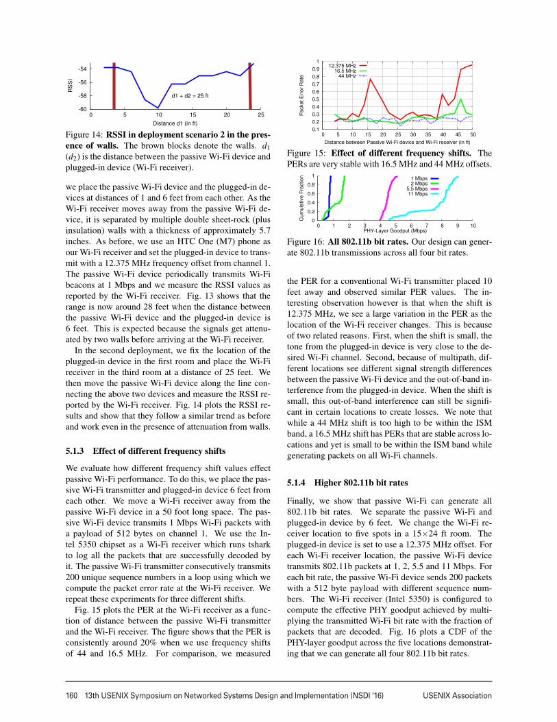
Figure 14: RSSI in deployment scenario 2 in the pres-ence of walls. The brown blocks denote the walls. d1(d2) is the distance between the passive Wi-Fi device andplugged-in device (Wi-Fi receiver).
we place the passive Wi-Fi device and the plugged-in de-vices at distances of 1 and 6 feet from each other. As theWi-Fi receiver moves away from the passive Wi-Fi de-vice, it is separated by multiple double sheet-rock (plusinsulation) walls with a thickness of approximately 5.7inches. As before, we use an HTC One (M7) phone asour Wi-Fi receiver and set the plugged-in device to trans-mit with a 12.375 MHz frequency offset from channel 1.The passive Wi-Fi device periodically transmits Wi-Fibeacons at 1 Mbps and we measure the RSSI values asreported by the Wi-Fi receiver. Fig. 13 shows that therange is now around 28 feet when the distance betweenthe passive Wi-Fi device and the plugged-in device is6 feet. This is expected because the signals get attenu-ated by two walls before arriving at the Wi-Fi receiver.
In the second deployment, we fix the location of theplugged-in device in the first room and place the Wi-Fireceiver in the third room at a distance of 25 feet. Wethen move the passive Wi-Fi device along the line con-necting the above two devices and measure the RSSI re-ported by the Wi-Fi receiver. Fig. 14 plots the RSSI re-sults and show that they follow a similar trend as beforeand work even in the presence of attenuation from walls.
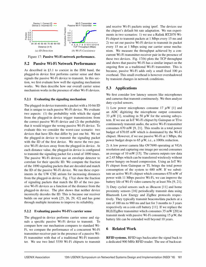
5.1.3 Effect of different frequency shifts
We evaluate how different frequency shift values effectpassive Wi-Fi performance. To do this, we place the pas-sive Wi-Fi transmitter and plugged-in device 6 feet fromeach other. We move a Wi-Fi receiver away from thepassive Wi-Fi device in a 50 foot long space. The pas-sive Wi-Fi device transmits 1 Mbps Wi-Fi packets witha payload of 512 bytes on channel 1. We use the In-tel 5350 chipset as a Wi-Fi receiver which runs tsharkto log all the packets that are successfully decoded byit. The passive Wi-Fi transmitter consecutively transmits200 unique sequence numbers in a loop using which wecompute the packet error rate at the Wi-Fi receiver. Werepeat these experiments for three different shifts.
Fig. 15 plots the PER at the Wi-Fi receiver as a func-tion of distance between the passive Wi-Fi transmitterand the Wi-Fi receiver. The figure shows that the PER isconsistently around 20% when we use frequency shiftsof 44 and 16.5 MHz. For comparison, we measured
0.1
0.2
0.3
0.4
0.5
0.6
0.7
0.8
0.9
1
0 5 10 15 20 25 30 35 40 45 50
Packet E
rror
Rate
Distance between Passive Wi-Fi device and Wi-Fi receiver (in ft)
12.375 MHz16.5 MHz
44 MHz
Figure 15: Effect of different frequency shifts. ThePERs are very stable with 16.5 MHz and 44 MHz offsets.
0
0.2
0.4
0.6
0.8
1
0 1 2 3 4 5 6 7 8 9 10
Cum
ula
tive F
raction
PHY-Layer Goodput (Mbps)
1 Mbps2 Mbps
5.5 Mbps11 Mbps
Figure 16: All 802.11b bit rates. Our design can gener-ate 802.11b transmissions across all four bit rates.
the PER for a conventional Wi-Fi transmitter placed 10feet away and observed similar PER values. The in-teresting observation however is that when the shift is12.375 MHz, we see a large variation in the PER as thelocation of the Wi-Fi receiver changes. This is becauseof two related reasons. First, when the shift is small, thetone from the plugged-in device is very close to the de-sired Wi-Fi channel. Second, because of multipath, dif-ferent locations see different signal strength differencesbetween the passive Wi-Fi device and the out-of-band in-terference from the plugged-in device. When the shift issmall, this out-of-band interference can still be signifi-cant in certain locations to create losses. We note thatwhile a 44 MHz shift is too high to be within the ISMband, a 16.5 MHz shift has PERs that are stable across lo-cations and yet is small to be within the ISM band whilegenerating packets on all Wi-Fi channels.
5.1.4 Higher 802.11b bit rates
Finally, we show that passive Wi-Fi can generate all802.11b bit rates. We separate the passive Wi-Fi andplugged-in device by 6 feet. We change the Wi-Fi re-ceiver location to five spots in a 15×24 ft room. Theplugged-in device is set to use a 12.375 MHz offset. Foreach Wi-Fi receiver location, the passive Wi-Fi devicetransmits 802.11b packets at 1, 2, 5.5 and 11 Mbps. Foreach bit rate, the passive Wi-Fi device sends 200 packetswith a 512 byte payload with different sequence num-bers. The Wi-Fi receiver (Intel 5350) is configured tocompute the effective PHY goodput achieved by multi-plying the transmitted Wi-Fi bit rate with the fraction ofpackets that are decoded. Fig. 16 plots a CDF of thePHY-layer goodput across the five locations demonstrat-ing that we can generate all four 802.11b bit rates.
10
USENIX Association 13th USENIX Symposium on Networked Systems Design and Implementation (NSDI ’16) 161
0 0.2 0.4 0.6 0.8
1
20 30 40 50 60 70 80 90 100
Fra
ction
Distance (in ft)
Device 1: Correct IDDevice 2: Incorrect ID
0 0.2 0.4 0.6 0.8
1
4 5 6 7 8 9 10 11 12 13 14Cum
ula
tive F
raction
TCP Throughput (Mbps)
Wi-Fi TransmitterPassive Wi-Fi Transmitter
(a) ID Detection (b) Wi-Fi Coexistence
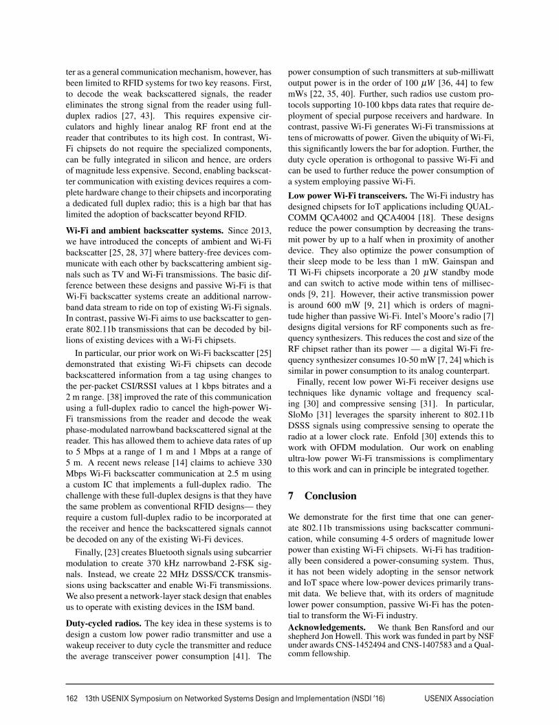
Figure 17: Passive Wi-Fi network performance.
5.2 Passive Wi-Fi Network PerformanceAs described in §3.1 to coexist in the ISM band, theplugged-in device first performs carrier sense and thensignals the passive Wi-Fi device to transmit. In this sec-tion, we first evaluate how well the signaling mechanismworks. We then describe how our overall carrier sensemechanism works in the presence of other Wi-Fi devices.
5.2.1 Evaluating the signaling mechanism
The plugged-in device transmits a packet with a 10-bit IDthat is unique to each passive Wi-Fi device. We evaluatetwo aspects: (1) the probability with which the signalfrom the plugged-in device trigger transmissions fromthe correct passive Wi-Fi device and (2) the probabilitythat it would trigger the wrong passive Wi-Fi device. Toevaluate this we consider the worst-case scenario: twodevices that have IDs that differ by just one bit. We setthe plugged-in device to transmit the signaling packetwith the ID of the first device. We move the two pas-sive Wi-Fi devices away from the plugged-in device. Ateach distance value, the plugged-in device is configuredto transmit the signaling packet for a total of 1890 times.The passive Wi-Fi devices use an envelope detector tocorrelate for their specific ID. We compute the fractionof the 1890 signaling packets that are decoded and matchthe ID of the passive Wi-Fi device. We run these exper-iments in the UW CSE atrium for increasing distancesfrom the plugged-in device. Fig. 17(a) show the fractionof signaling packets that match the ID of the two pas-sive Wi-Fi devices as a function of the distance from theplugged-in device. The plot shows that neither deviceincorrectly decodes the ID. This is because our receiverbuilds on our prior work [25, 26, 29, 42] and has gonethrough multiple iterations to improve its reliability.
5.2.2 Evaluating passive Wi-Fi’s carrier sense
The plugged-in device performs carrier sense and sig-nals a specific passive Wi-Fi device to transmit. Tocompare how our mechanism compares to standard Wi-Fi, we compare the performance of a concurrent Wi-Fitransmitter-receiver pair in the presence of a passive Wi-Fi transmitter with that of a traditional Wi-Fi transmit-ter. We use two Intel 5350 Wi-Fi chipsets to transmit
and receive Wi-Fi packets using iperf. The devices usethe chipset’s default bit rate adaptation. We run experi-ments in two scenarios: 1) we use a Ralink RT2070 Wi-Fi chipset to transmit packets at 1 Mbps every 15 ms and2) we set our passive Wi-Fi device to transmit its packetevery 15 ms at 1 Mbps using our carrier sense mecha-nism. We measure the throughput achieved by a con-current Wi-Fi transmitter-receiver pair in the presence ofthese two devices. Fig. 17(b) plots the TCP throughputand shows that passive Wi-Fi has a similar impact on theongoing flow as a traditional Wi-Fi transmitter. This isbecause, passive Wi-Fi adds only a small fixed 100 µsoverhead. This small overhead is however overshadowedby transient changes in network conditions.
5.3 ApplicationsWe first consider low latency sensors like microphonesand cameras that transmit continuously. We then analyzeduty-cycled sensors.
1) Low power microphones consume 17 µW [1] andan ADC digitizing the microphone output consumes33 µW [1], resulting in 50 µW for the sensing subsys-tem. If we use an IoT Wi-Fi chipset by Gainspan or TI tocontinuously transmit audio, the active Wi-Fi transmitterconsumes 670 mW [9, 21]. This results in a total powerbudget of 670.05 mW which is dominated by the Wi-Fichipset. However, if we use passive Wi-Fi at 1 Mbps, thepower budget drops to 65 µW, i.e., a 1000x reduction.
2) A low power camera like OV7690 operating at VGAresolution and capturing one image per second consumesan average of 10 mW [15]. The camera outputs raw dataat 2.45 Mbps which can be transferred wirelessly withoutpower hungry on-board compression. Using an IoT Wi-Fi chipset from Gainspan or TI, brings the total powerconsumption of the system to 680 mW. If we substi-tute an active Wi-Fi chipset which consumes 670 mW ofpower with 11 Mbps passive Wi-Fi, we can improve thebattery life of Wi-Fi video camera by at least 50x [9, 21].
3) Duty cycled sensors such as iBeacon [11] and homeproximity sensors [16] periodically transmit data usingBluetooth Low Energy and ZigBee protocols respec-tively. They typically transmit beacons/data packets at arate of 100 ms to 900 ms and last for 3 months to 3 yearsrespectively on a coin cell battery [11]. If we replace theBLE/ZigBee transmitter which consumes 35 mW [20] intransmit mode with passive Wi-Fi consuming 15 µW, thebattery life can be extended well beyond 10 years.
6 Related Work
RFID systems. RFID tags backscatter the signal back toa dedicated 900 MHz RFID reader. The use of backscat-
11
162 13th USENIX Symposium on Networked Systems Design and Implementation (NSDI ’16) USENIX Association
ter as a general communication mechanism, however, hasbeen limited to RFID systems for two key reasons. First,to decode the weak backscattered signals, the readereliminates the strong signal from the reader using full-duplex radios [27, 43]. This requires expensive cir-culators and highly linear analog RF front end at thereader that contributes to its high cost. In contrast, Wi-Fi chipsets do not require the specialized components,can be fully integrated in silicon and hence, are ordersof magnitude less expensive. Second, enabling backscat-ter communication with existing devices requires a com-plete hardware change to their chipsets and incorporatinga dedicated full duplex radio; this is a high bar that haslimited the adoption of backscatter beyond RFID.
Wi-Fi and ambient backscatter systems. Since 2013,we have introduced the concepts of ambient and Wi-Fibackscatter [25, 28, 37] where battery-free devices com-municate with each other by backscattering ambient sig-nals such as TV and Wi-Fi transmissions. The basic dif-ference between these designs and passive Wi-Fi is thatWi-Fi backscatter systems create an additional narrow-band data stream to ride on top of existing Wi-Fi signals.In contrast, passive Wi-Fi aims to use backscatter to gen-erate 802.11b transmissions that can be decoded by bil-lions of existing devices with a Wi-Fi chipsets.
In particular, our prior work on Wi-Fi backscatter [25]demonstrated that existing Wi-Fi chipsets can decodebackscattered information from a tag using changes tothe per-packet CSI/RSSI values at 1 kbps bitrates and a2 m range. [38] improved the rate of this communicationusing a full-duplex radio to cancel the high-power Wi-Fi transmissions from the reader and decode the weakphase-modulated narrowband backscattered signal at thereader. This has allowed them to achieve data rates of upto 5 Mbps at a range of 1 m and 1 Mbps at a range of5 m. A recent news release [14] claims to achieve 330Mbps Wi-Fi backscatter communication at 2.5 m usinga custom IC that implements a full-duplex radio. Thechallenge with these full-duplex designs is that they havethe same problem as conventional RFID designs— theyrequire a custom full-duplex radio to be incorporated atthe receiver and hence the backscattered signals cannotbe decoded on any of the existing Wi-Fi devices.
Finally, [23] creates Bluetooth signals using subcarriermodulation to create 370 kHz narrowband 2-FSK sig-nals. Instead, we create 22 MHz DSSS/CCK transmis-sions using backscatter and enable Wi-Fi transmissions.We also present a network-layer stack design that enablesus to operate with existing devices in the ISM band.
Duty-cycled radios. The key idea in these systems is todesign a custom low power radio transmitter and use awakeup receiver to duty cycle the transmitter and reducethe average transceiver power consumption [41]. The
power consumption of such transmitters at sub-milliwattoutput power is in the order of 100 µW [36, 44] to fewmWs [22, 35, 40]. Further, such radios use custom pro-tocols supporting 10-100 kbps data rates that require de-ployment of special purpose receivers and hardware. Incontrast, passive Wi-Fi generates Wi-Fi transmissions attens of microwatts of power. Given the ubiquity of Wi-Fi,this significantly lowers the bar for adoption. Further, theduty cycle operation is orthogonal to passive Wi-Fi andcan be used to further reduce the power consumption ofa system employing passive Wi-Fi.
Low power Wi-Fi transceivers. The Wi-Fi industry hasdesigned chipsets for IoT applications including QUAL-COMM QCA4002 and QCA4004 [18]. These designsreduce the power consumption by decreasing the trans-mit power by up to a half when in proximity of anotherdevice. They also optimize the power consumption oftheir sleep mode to be less than 1 mW. Gainspan andTI Wi-Fi chipsets incorporate a 20 µW standby modeand can switch to active mode within tens of millisec-onds [9, 21]. However, their active transmission poweris around 600 mW [9, 21] which is orders of magni-tude higher than passive Wi-Fi. Intel’s Moore’s radio [7]designs digital versions for RF components such as fre-quency synthesizers. This reduces the cost and size of theRF chipset rather than its power — a digital Wi-Fi fre-quency synthesizer consumes 10-50 mW [7, 24] which issimilar in power consumption to its analog counterpart.
Finally, recent low power Wi-Fi receiver designs usetechniques like dynamic voltage and frequency scal-ing [30] and compressive sensing [31]. In particular,SloMo [31] leverages the sparsity inherent to 802.11bDSSS signals using compressive sensing to operate theradio at a lower clock rate. Enfold [30] extends this towork with OFDM modulation. Our work on enablingultra-low power Wi-Fi transmissions is complimentaryto this work and can in principle be integrated together.
7 Conclusion
We demonstrate for the first time that one can gener-ate 802.11b transmissions using backscatter communi-cation, while consuming 4-5 orders of magnitude lowerpower than existing Wi-Fi chipsets. Wi-Fi has tradition-ally been considered a power-consuming system. Thus,it has not been widely adopting in the sensor networkand IoT space where low-power devices primarily trans-mit data. We believe that, with its orders of magnitudelower power consumption, passive Wi-Fi has the poten-tial to transform the Wi-Fi industry.Acknowledgements. We thank Ben Ransford and ourshepherd Jon Howell. This work was funded in part by NSFunder awards CNS-1452494 and CNS-1407583 and a Qual-comm fellowship.
12
USENIX Association 13th USENIX Symposium on Networked Systems Design and Implementation (NSDI ’16) 163
References
[1] ADMP801. http://www.cdiweb.com/datasheets/invensense/ADMP801_2_Page.pdf.
[2] Altera de1 fpga development board. http://www.terasic.com.tw/cgi-bin/page/archive.pl?No=83.
[3] Android wi-fi analyzer. https://play.google.com/store/apps/details?id=com.farproc.wifi.analyzer&hl=en.
[4] Atheros targets cellphone with wi-fi chip.http://www.eetimes.com/document.asp?doc_id=1172134.
[5] Cadence rfspectre. http://www.cadence.com/products/rf/spectre_rf_simulation/pages/default.aspx.
[6] Co-existence of wi-fi and bluetooth ra-dios by marvell. http://www.marvell.com/wireless/assets/Marvell-WiFi-Bluetooth-Coexistence.pdf.
[7] Connecting the future: The latest research fromintel labs. http://download.intel.com/newsroom/kits/idf/2012_fall/pdfs/IDF2012_Justin_Rattner.pdf.
[8] Dropcam. https://nest.com/camera/meet-nest-cam/?dropcam=true.
[9] Gainspan gs1500m. http://www.alphamicro.net/media/412417/gs1500m_datasheet_rev_1_4.pdf.
[10] Hms190bms8 by hittite microwave devices.https://www.hittite.com/content/documents/data_sheet/hmc190bms8.pdf.
[11] ibeacons. http://beekn.net/2014/04/will-apple-pull-plug-ibeacon-devices/.
[12] Ieee 802.11 standard, 2012. http://standards.ieee.org/getieee802/download/802.11-2012.pdf.
[13] Max2830 by maxim. https://datasheets.maximintegrated.com/en/ds/MAX2830.pdf.
[14] Nasa news release: A wi-fi reflector chip to speedup wearables. http://www.jpl.nasa.gov/news/news.php?feature=4663.
[15] Ovm 7690 camera module. http://www.ovt.com/uploads/parts/OVM7690_PB(1.0)_web.pdf.
[16] Proximity sensors. https://www.ia.omron.com/products/category/sensors/proximity-sensors/.
[17] Qualcomm atheros 9462. http://www.qca.qualcomm.com/wp-content/uploads/2013/11/AR9462.pdf.
[18] Qualcomm qca4002 and qca4004. http://www.eeworld.com.cn/zt/wireless/downloads/QCA4002-4004FIN.pdf.
[19] Synopsis design complier. http://www.synopsys.com/Tools/Implementation/RTLSynthesis/DesignCompiler/Pages/default.aspx.
[20] TI CC2541. http://www.ti.com/lit/ds/symlink/cc2541.pdf.
[21] TI CC3100MOD. http://www.ti.com/lit/ds/symlink/cc3100mod.pdf.
[22] J. Ayers, N. Panitantum, K. Mayaram, and T. S.Fiez. A 2.4 ghz wireless transceiver with 0.95 nj/blink energy for multi-hop battery-freewireless sen-sor networks. In VLSI Circuits (VLSIC), 2010 IEEESymposium on, pages 29–30. IEEE, 2010.
[23] J. Ensworth and M. Reynolds. Every smart phone isa backscatter reader: Modulated backscatter com-patibility with bluetooth 4.0 low energy (ble) de-vices. In RFID, 2015 IEEE International Confer-ence on.
[24] K. Greene. Intel’s tiny wi-fi chip could have a bigimpact. MIT Technology review, 2012.
[25] B. Kellogg, A. Parks, S. Gollakota, J. R. Smith, andD. Wetherall. Wi-fi backscatter: Internet connec-tivity for rf-powered devices. In Proceedings of the2014 ACM Conference on SIGCOMM, 2014.
[26] B. Kellogg, V. Talla, and S. Gollakota. Bringinggesture recognition to all devices. In Usenix NSDI,volume 14, 2014.
[27] P. B. Khannur, X. Chen, D. L. Yan, D. Shen,B. Zhao, M. K. Raja, Y. Wu, R. Sindunata, W. G.Yeoh, and R. Singh. A universal uhf rfid reader icin 0.18-µm cmos technology. Solid-State Circuits,IEEE Journal of, 43(5):1146–1155, 2008.
13
164 13th USENIX Symposium on Networked Systems Design and Implementation (NSDI ’16) USENIX Association
[28] V. Liu, A. Parks, V. Talla, S. Gollakota, D. Wether-all, and J. R. Smith. Ambient backscatter: Wire-less communication out of thin air. In Proceedingsof the ACM SIGCOMM 2013 Conference on SIG-COMM, 2013.
[29] V. Liu, V. Talla, and S. Gollakota. Enabling in-stantaneous feedback with full-duplex backscatter.In Proceedings of the 20th annual internationalconference on Mobile computing and networking,pages 67–78. ACM, 2014.
[30] F. Lu, P. Ling, G. M. Voelker, and A. C. Snoeren.Enfold: downclocking ofdm in wifi. In Proceed-ings of the 20th annual international conference onMobile computing and networking, pages 129–140.ACM, 2014.
[31] F. Lu, G. M. Voelker, and A. C. Snoeren. Slomo:Downclocking wifi communication. In NSDI,pages 255–258, 2013.
[32] J. Manweiler and R. Roy Choudhury. Avoiding therush hours: Wifi energy management via traffic iso-lation. In MobiSys, 2011.
[33] R. Mittal, A. Kansal, and R. Chandra. Empoweringdevelopers to estimate app energy consumption. InMobiCom, 2012.
[34] P. Nikitin and K. Rao. Theory and measurementof backscattering from RFID tags. Antennas andPropagation Magazine, IEEE, 48(6):212 –218, de-cember 2006.
[35] B. Otis, Y. Chee, R. Lu, N. Pletcher, andJ. Rabaey. An ultra-low power mems-based two-channel transceiver for wireless sensor networks.In VLSI Circuits, 2004. Digest of Technical Papers.2004 Symposium on, pages 20–23. IEEE, 2004.
[36] J. Pandey and B. P. Otis. A sub-100 w mics/ismband transmitter based on injection-locking and fre-quency multiplication. Solid-State Circuits, IEEEJournal of, 46(5):1049–1058, 2011.
[37] A. N. Parks, A. Liu, S. Gollakota, and J. R.Smith. Turbocharging ambient backscatter commu-nication. In Proceedings of the 2014 ACM Confer-ence on SIGCOMM, 2014.
[38] D. Pharadia, K. R. Joshi, M. Kotaru, and S. Katti.Backfi: High throughput wifi backscatter. In Pro-ceedings of the 2015 ACM Conference on SpecialInterest Group on Data Communication, 2015.
[39] J. G. Proakis and M. Salehi. Digital communica-tions. 2005. McGraw-Hill, New York.
[40] J. Rabaey, J. Ammer, B. Otis, F. Burghardt,Y. Chee, N. Pletcher, M. Sheets, and H. Qin. Ultra-low-power design. Circuits and Devices Magazine,IEEE, 22(4):23–29, 2006.
[41] J. M. Rabaey, M. J. Ammer, J. L. da Silva, D. Patel,and S. Roundy. Picoradio supports ad hoc ultra-lowpower wireless networking. Computer, 33(7):42–48, 2000.
[42] A. P. Sample, D. J. Yeager, P. S. Powledge, A. V.Mamishev, and J. R. Smith. Design of an rfid-based battery-free programmable sensing platform.Instrumentation and Measurement, IEEE Transac-tions on, 57(11):2608–2615, 2008.
[43] C. Ying and Z. Fu-Hong. A system design for uhfrfid reader. In Communication Technology, 2008.ICCT 2008. 11th IEEE International Conferenceon, pages 301–304. IEEE, 2008.
[44] F. Zhang, Y. Zhang, J. Silver, Y. Shakhsheer,M. Nagaraju, A. Klinefelter, J. Pandey, J. Boley,E. Carlson, A. Shrivastava, et al. A batteryless19µw mics/ism-band energy harvesting body areasensor node soc. In Solid-State Circuits ConferenceDigest of Technical Papers (ISSCC), 2012 IEEE In-ternational, pages 298–300. IEEE, 2012.
14

![OdakyuAndroid t Google play] Wi-Fi Android ios t App Store] Wi-Fi [App Store] [iPhone Profile) Wi-Fi # —E Odakyu Odakyu Free Wi-Fi Android [Google play] WI-Fi Android [App Wi-Fi](https://img.pdfslide.us/doc/110x75/5fcc31f69b77e950d81a9828/android-t-google-play-wi-fi-android-ios-t-app-store-wi-fi-app-store-iphone.jpg)