Embed Size (px)
Citation preview

Passive structural response control of unconventional under-deck
cable-stayed bridges
*Ieva Misiunaite1) and Algirdas Juozapaitis2)
1), 2) Department of Bridges and Special Structures, Vilnius Gediminas Technical
University, Sauletekio al. 11, Vilnius LT-10223, Lithuania 1) [email protected]
ABSTRACT
This study aims to provide a framework for the passive control of the structural response of steel under-deck cable-stayed (UDCS) bridges. The performance of UDCS bridges with an unconventional layout of a cable-staying system is examined by means of Direct Analysis using effective structural response control technique. Recently, the advanced analysis has been remained a tool for researchers rather than for practitioners. This paper describes practical applicability of this advanced analysis, accounting for second-order effects and both geometrical and mechanical imperfections by means of the generalized imperfection factor. The improvements provided by direct analysis, in the determination of structural response for checking the in-plane buckling on the actual unsupported length in the plane of bending and eliminating the need of effective length factor, make it an effective tool for advanced structures analysis. The proposed method concerns the development of structural response control by adopting appropriate “rational eccentricity” of cable-staying system rather than conservative presstressing of cable stays. The structural behavior of UDCS bridge is analyzed using the direct method and structural response control, and the results obtained are discussed and compared with structural behavior of the same morphology uncontrolled UDCS bridge by means of the FEM code, ANSYS. On the basis of such comparative studies, several conclusions are drawn concerning the efficiency of the proposed control technique. 1) PhD Student 2) Professor Note: Copied from the manuscript submitted to “Steel and Composite Structures, An International
Journal” for presentation at ASEM13 Congress
843

1. INTRODUCTION Normally, cable supported bridges have been associated with three types of bridges such as suspension, cable-stayed and extradosed. In the sequence of developments of such type bridges and necessity, to solve engineering problems caused by unconventional environmental conditions the new type of cable supported bridges aroused. There is still no common agreement for the name of this kind of bridge, and in literature it appears as self-anchored suspended deck bridge, bridge supported from below and under-deck cable-stayed (UDCS) bridge. For this study, the last term is used, which was proposed by Ruiz-Teran and Aparicio in 2005 when the first author submitted her doctoral thesis written on the structural behaviour of such kind of bridges. The concept of UDCS bridge is such that intermediate pylons can be replaced by supporting system of stay cables and struts, and thus the cable-staying system takes placed below the deck rather than above as in conservative cable-stayed bridge. The replacement of the intermediate pylons with a cable-staying system solves many engineering problems such as:
a) Insufficient soils for pylons installation; b) Suspension of the bridge exploitation during reconstruction or maintenance; c) To widen the clearance of the highway overpasses; d) Reduced maintenance – sheltering the supporting structural elements from
destroying environmental conditions and vandalism; e) Provision of the catwalk for construction and maintenance by means of the
cables. Previously mentioned advantages have made this type of bridge the issue of interest for the last four decades. Though despite functionality and successful practical implementation (Norris 2010, Tsunomoto and Ohnuma 2002, Holgate 1997, Schlaich and Werwigk 2001, Watanabe 2002) from a design point of view UDCS bridges still remain incompletely explored engineering problem. A significant contribution to this case was made by Ruiz-Teran and Aparicio. Studying the unconventional cable-stayed bridges Ruiz-Teran presented a PhD thesis (2005) on such type bridges structural behavior and design criteria. Supervised by professor Aparicio researcher declared the state of art of two new types of bridges known as under-deck cable-stayed bridges and combined cable-stayed bridges (2007a), obtained the governing parameters and analyzed structural behavior of considering bridges (2007b, 2008a, 2008b). Moreover, some attention was paid to the issues related to the dynamic behavior, considering the amplification factors (Ruiz-Teran and Aparicio 2007c), accidental breakage of the stay cables (Ruiz-Teran and Aparicio 2009a) and vibration (Ruiz-Teran and Aparicio 2009b). Before research of Ruiz-Teran and Aparicio the issues addressed to the structural behavior of the UDCS structures concern mostly the externally prestressed concrete slabs or beams (Menn and Gauvreau 1987, Virlogeux et al. 1994, Harajli et al. 1999, Aravinthan et al. 2005, Lou et al. 2012). However, there are some works which have been performed by Muttoni (1997, 2002) and emphasize the novelty of an unconventional position of the cable-staying system. It should be noted that, in most of these studies, structural behavior of the deck have been analyzed by means of prestressed concrete element. The particular case of steel UDCS structures was mostly considered with the approach of roof beam-string structures (Juozapaitis and Kvedaras
844

1999, Wu 2008, Xue and Liu 2009, Saitoh and Okada 1999). In all previously mentioned studies, structural behavior of the UDCS structures relays on the prestressing of the stay cables as the way to control structural behavior of the deck. This paper presents a new point of view for the possibility to control structural response of the main steel girder of the UDCS bridges by means of eccentric anchoring of the cable-staying system. In particular, this study aims at providing a contribution to a better understanding of the structural behavior and more efficient analysis of the UDCS bridges. Because when the under-deck stay cables are introduced into the deck, by means of struts, thus the upward deviation force equal to the vertical reaction that would have been provided by the eliminated pylons is initiated (Ruiz-Teran and Aparicio 2010). Due to direct anchoring of cable-staying system when the external forces are applied the structural behaviour of the main girder of the bridge approach the structural behaviour of a beam-column element with the additional intermediate supports (Misiunaite and Juozapaitis 2012) and this makes it inevitably nonlinear problem. This study deals only with the in-plane behavior of a simple-span UDCS bridge. Paper primary focuses on emphasizing the relevance, in terms of both efficiency and accuracy, of adequately determined values of rational eccentricity erac to be embedded in the direct analysis of the whole structure. In order to illustrate the concepts and procedures addressed, an isolated one-span steel girder element by means of beam-column with appropriate loading and support conditions is considered. A calculation model of an isolated element is embedded into considering bridge structure, and the analyses of the structural behaviour of such type of bridge using derived governing equations is performed, and validated by the results of finite element analysis carried out with a nonlinear solver of ANSYS. Moreover, the comparative analysis of simple-span UDCS bridges with and without flexural response control is carried out to emphasize the efficiency of the proposed technique. On the basis of the above studies, it is possible to draw a number of conclusions concerning the efficiency, accuracy and validity of structural response control and also to show that this efficiency is bound to be significantly improved if direct analysis is used. 2. PROPOSED FAILURE SURFACE
Consider innovative steel structure of simple-span double-level UDCS bridge of four equal spans (l). The connections between the span elements of the main girder assumed to be hinged in contrary to structural schemes of conservative UDCS bridges. This development increases a resistance of the main girder for bending about one principle axis with applying effective technique of flexural response control. The variation in the length of struts (lSt) determines the changes in the layout of the cable-staying system of the double-level UDCS bridge. The structural schemes examined, shown in Fig. 1 a) and b) are the bridges with passing and framing first level cable-staying system, respectively. Fig.1 shows that the double-level UDCS bridge is formed of three independent conservative simple-span UDCS structures with mono cable-staying system (Fig. 2).
845

(a) Passing first level cable-staying system
(b) Framing first level cable-staying system
Fig. 1 Structural schemes of the double-level UDCS bridge The displacements and internal forces of the double-level UDCS bridge subjected to external transverse distributed load can be determined by considering appropriate calculation model of the conventional UDCS bridge structure with mono cable-staying system shown in Fig. 2.
Fig. 2 Calculation model of UDCS bridge with mono cable-staying system The main girder of the considering bridge is subjected to simultaneous bending and compression due to applied transverse distributed load and direct anchorage of the cable-staying system. Distributed transversal load introduces axial compression into the strut and tension into the cable stays. It is obvious that the value of this axial force is inversely proportional to the length of the strut (Fig. 2). To describe the technique for structural response control consider calculation model of the individual member of the main girder undergoing large displacements shown in Fig. 3 under simultaneous action of the distributed transversal load q and compression force Nc applied with the appropriate eccentricity. The deflection (v) is measured from the initially imperfect configuration (v0) with the amplitude of vm0.
l l l l
L
lSt,
2
lSt,
1 lSt,
2
l l l l
L
lSt,
2
lSt,
1
lSt,
2
l l
L
lSt
C
S
v0v
erac
erac
q
EI=const. EI=const.
846

Fig. 3 Calculation model of an individual member of the main girder 3. ANALYSIS METHODOLOGY
This section discusses the requirements that must be satisfied for the flexural response control using a direct analysis. For steel beam-column elements, AISC 360-10 and EN 1993-1-1 (2003) Specifications defines specific elastic analysis and design methods, these are: (1) The direct analysis method, detailed in Section C 1.1 of AISC 360-10 (2010), (2) The Global analysis, detailed in Section 5.2 of EN 1993-1-1 (2003). Due to the improvements provided by the direct analysis method in the calculations of the internal forces and moments, both previously mentioned Specifications base their determination of structural response for checking the in-plane buckling on the actual unsupported length in the plane of bending. In short, the need to use the effective length concept is eliminated. According to this advantage of the direct analysis method it may be generally applicable to many types of innovative and complex structures, when the following nominal geometric imperfections, residual stresses and material idealizations are included in the analysis (White et al. 2006):
A sinusoidal or parabolic out-of- plumbness with maximum amplitude of 0m /1000v l , where l is the unsupported length in the plane of bending.
The Lehigh (Galambos and Ketter 1959) residual stress pattern An elastic-perfectly plastic material stress-strain response.
3.1 Imperfections The geometrical imperfections will be assumed to be sinusoidal:
0 0m sinz
v vl
(1)
The magnitude of the equivalent geometrical imperfections by introducing generalized imperfection factor becomes:
0m
Wv
A (2)
The value of the generalized imperfection factor originally was obtained by Robertson in 1925 and has been varying over the years and for this case assumed in the form prepared by Maquoi-Ronald for EC3:
l
EI=const.vm0
vm
v0
v
Nc
q
Nc
erac erac
847

0,2 (3)
Where 1/2
20,001 / ya E f is an imperfection factor based on the column strength
curves and the multiplier 0.001 refers to the maximum tolerance for the elements out-of-straightness specified in many design codes. By substituting Eq. (3) into Eq. (2) the magnitude of the equivalent geometrical imperfections factor can be rewritten as:
0m 0,2W
vA
(4)
3.2 Governing Equations The governing equations derived applying the moderately large displacements theory to isolated steel member shown in Fig. 3. Attention is paid to the requirements set for the performance of the direct analysis and, in particular, eccentric application of the axial compression (Nc). The deflection (v) is measured from the initially imperfect configuration, and the normal force is constant along the length of the element, thus the moment equilibrium equation becomes:
z c 0 c'' '' 0M N v v N e q (5)
The relation between internal axial force (Nc) and flexural rigidity (EI) can be expressed as:
c2 Nk
EI (6)
Thus, Eq. (5) can be rewritten as:
iv 2 2 20m'' ( sin ) ''
z qv k v k v k e
l EI
(7)
Introducing:
2
2
1
1
n
kl
(8)
General solution of Eq. (7) is:
2
1 2 3 4 0m 2sin cos sin
2
z qzv C kz C kz C z C nv e
l EIk
(9)
By combining general solution of Eq. (7) with the boundary conditions for the simply supported steel element shown in Fig. 3:
2 2
0 and
0 and '' 0 and ''
z z l
v v k e v v k e
(10)
Thus, the deflection is obtained as:
848

4 3
0m4 2sin cos 1 1 sin
22
ql qzl z zklv e tg kz kz nvl lEI kl EI kl
(11)
Accordingly, by ''zM EIv , the moment is given by:
22 2 2
0m2 2 2 2sin cos sin
2z
EIe klql ql zklM tg kz kz EInvll lkl kl
(12)
4. STRUCTURAL RESPONSE CONTROL As a matter of fact, the main objective of this paper is to provide a contribution to shed some new light on a number of issues related to the effective utilization of the cross-sections in the design of steel structures. It is well-know that optimum distribution of the internal forces increases efficiency in the structures design. Considering bending moment diagram of the conservative multiple-span bridge it is clear that the bending moment distribution would be much effective for the continuous structure than simple-span. For the simple-span structure, the extreme hogging moment appears at the mid-span of the girder and governs the utilization of the cross-section. The proposed method aims to obtain the efficiency in cross-section utilization of the main girder and distribution of the internal forces at different points of the structure (bending moment in the midspan section, bending moment in the support section and axial force). Since the loads acting upon the UDCS bridge depend on its geometry, this technique is iterative and is presented in the flowchart shown in Fig. 4.
849

Fig. 4 Flowchart for performing the structural response control of the double-level UDCS bride
It should be noted that this method is valid just for the simple-span bridges.
4.1 Rational eccentricity As previously mentioned, the simple-span structures have the ineffective distribution of the internal forces: the extreme value of bending moment at the midspan sections and zero at the support sections. The eccentric application of axial force by means of eccentric anchoring of cable-staying system would evoke bending moments at the support sections. Thus, if the cross-section of the girder is assumed to be constant, the condition for the rational moment control becomes (Juozapaitis et al. 2007):
0 / 2M z M z l (13)
By combining Eq. (12) with the condition (13) the rational eccentricity is given by:
2 40m
42
1 coscos 22
1 cos 1 cos2 2
rac
klklnv qle
kl klEI klkl
(14)
And the rational moment:
850

22
0m
2 2
cos 12
cos2
rac
rac
klq EIe klEInvM
kll l
(15)
4.2 Variables In order to enable a full grasp of all concepts involved in selecting the appropriate erac values, some variables still requires further clarification. Equations for determining the rational values of eccentricity and bending moment include the undetermined variable kl, known as slenderness parameter. Slenderness parameter relies on an internal axial force according to Eq. (17) and can be expressed as:
cN
kl lEI
(16)
An internal axial force in conservative UDCS structure (Fig.2) for the first iteration may be obtained considering element in its undeformed position:
2
St8c
qLN
l (17)
Where L (m) is a span length of the structure and for the case shown in Fig. 1 is equal to 2L l ; Stl (m) is a length of a strut. According to double-level UDCS bridge design principles (Misiunaite et al. 2012) it follows that an axial force can be obtained as:
2 2
1 2
St,1 St,28 8c
qL qLN
l l (18)
Where L1 and L2 are the span lengths of first and second level substructures, St,1l and
St,2l are the lengths of the strut of the first and second level substructures respectively. The span to strut length relation shows that, for the constant span length the axial response of the girder can be partially controlled by varying the length of the strut. It is clear that increase in the length of the strut decreases the axial response. 5. NUMERICAL EVALUATION The application of the rational eccentricity including variations in the morphology of the cable-staying system by means of the struts length is demonstrated in this section using a simple-span UDCS bridge of four spans with double-level cable-staying system first reported by author et.al (2012). A symmetric distributed transverse load is applied to illustrate in-plane structural behavior of the main girder. Several different base modelling assumptions are implemented: slenderness parameter of the girder must be greater than 1.0 for the sufficient effect of the axial force in the interaction of bending and compression and the deflection of the bridge must meet the requirements for the serviceability limit state.
851

5.1 Structural properties and loads The examining UDCS bridge has 12 m span sub-girder, and that makes the whole length of the bridge 48 m. The cross-section of the girder is hot rolled European standard wide flange H beam HEB 400; struts are the hollow sections and cable stays are rods with the area of 18176 mm2 and 25447 mm2 respectively. Two models of the considering bridge are generated with the only difference being in the layout of cable-staying system by means of struts length. The first model of the double-level UDCS bridge with passing cable-staying system shown in Fig.5 is modelled using the 3000 mm strut length for the second level cable-staying systems and 4500 mm for the first one. For the second model (Fig.6) strut lengths are 1800 mm and 5000 mm for the second and first levels respectively and thus the cable-staying system gets a framing layout. The differences in the length of struts refer to the axial response in the girder and to the one of the base modeling assumption – slenderness parameter. The main girder of the first model has the slenderness parameter of 1.45 obtained after the first iteration performed according to flowchart shown in Fig. 4. For the convergence of the axial forces in second calculation model, two iterations were required, and after that slenderness parameter became equal to 1.53.
Fig. 5 First calculation model of the double-level UDCS bridge
Fig. 6 Second calculation model of the double-level UDCS bridge 5.2 Numerical model and analysis The numerical analysis is performed by means of the FEM code ANSYS, using beam elements for modelling main girder and link for the cable-staying system. Bridge
erac
12000 12000 12000
48000
3000
4500
3000
20 kN/m
12000
20 kN/m
12000 12000 12000 12000
48000
1800
5000 1
800
erac
852

girders contain the initial bow imperfections assumed to be sinusoidal and evaluated by spline with the amplitude rely on a generalized imperfection factor and an elastic-perfectly plastic stress-strain law (i.e., no strain hardening) is accounted. To avoid unnecessary modelling difficulties, a 2D model is adopted. The large displacement static analysis performed for the first and second models of the double-level UDCS bridges to obtain structural response of the girder. The structural response control procedure performed according to flowchart presented in Fig. 4. Convergence was achieved when the relative difference between two consecutive internal axial forces was smaller than a tolerance , which was assumed to be 1%. Comparative analysis uses the same calculation models of the UDCS bridge without flexural response control by means of centric anchorage of the cable-staying system. 5.3 Results The flexural response control has been performed by eccentric anchoring of cable-staying system and the rational eccentricity estimated by Eq. (14). For the first model, the numerical value of the rational eccentricity (erac) was 122 mm. The relative deference between axial forces in the girder estimated by Eq. (18) and obtained after analysis performed with ANSYS appeared to be 0.52% what was less than assumed convergence tolerance, thus just one iteration has been required. The second model of UDCS bridge (Fig. 6) for the first iteration had the rational eccentricity of 112 mm. For the achievement of convergence of the axial forces in the girder, two iterations were required, and finally the rational eccentricity became equal to 111 mm. Fig. 7 shows the first model of double-level UDCS bridge analyzed (subjected to a transverse distributed load q equal to 20 kN/m). The bending moment diagram displayed in Fig. 7 (a) show the rational moment (Mrac) values obtained by the non-linear solver of ANSYS and provided by the proposed expression of Eq. (15). The difference between extreme values of the bending moment equal to 0.36% thus a proper result of the flexural control is achieved. Moreover, the relative difference between numerical values of rational moment, obtained by Eq. (15) and non-linear solver ANSYS is 0.06%. This negligible difference shows that presented formula gives an accurate and safe solution.
(a) UDCS bridge with structural response control
216 kNm 216 kNm
216 kNm
216 kNm
216 kNm 216 kNm
216 kNm 216 kNm
216 kNm
853

(b) UDCS bridge without structural response control
Fig. 7 Comparison of the bending moment’s distribution into the main girder of UDCS bridge with passing cable-staying system
Figs. 7(a) and (b) show a comparison between the flexural responses of the UDCS bridge determined by adopting the described rational eccentricity and without it. It is clear that the use of the proposed structural response control technique determines effective utilization of the cross-section of the girder. Eccentric anchoring of the cable-staying system initiates hogging moments at the supports and decreases sagging bending moments at the mid-span sections 2.3 times in comparison to conservative solution of simple-span double-level UDCS bridge. Finally, by adopting the rational eccentricity, not just flexural response can be decreased but deformational either. Figs. 8(a) and (b) show the comparison between deformations of the double-level UDCS bridge with and without structural response control respectively. It is obvious that controlling structural response of the bridge increases its stability in comparison with conservative case. Stability is an issue of the high importance concerning bridge design.
(a) UDCS bridge with structural response control
(b) UDCS bridge without structural response control
Fig. 8 Comparison of the displacement’s of UDCS bridge with passing cable-staying system
Fig. 9 enables the comparison between the UDCS bridge (Fig. 6) with and without structural response control respectively. As in a previous example by adopting the rational eccentricity the effective distribution of the bending moments obtained, and the
503 kNm 503 kNm 503 kNm 503 kNm
95,5
2155,2
854
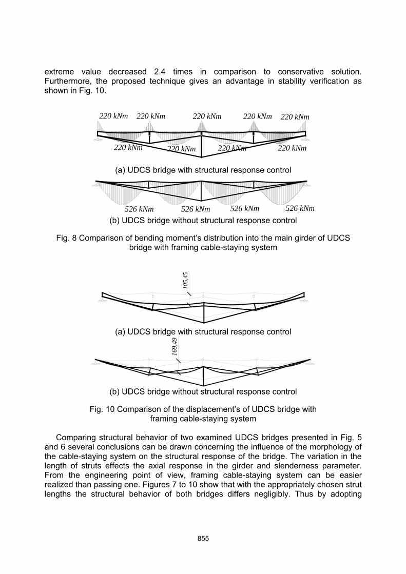
extreme value decreased 2.4 times in comparison to conservative solution. Furthermore, the proposed technique gives an advantage in stability verification as shown in Fig. 10.
(a) UDCS bridge with structural response control
(b) UDCS bridge without structural response control
Fig. 8 Comparison of bending moment’s distribution into the main girder of UDCS bridge with framing cable-staying system
(a) UDCS bridge with structural response control
(b) UDCS bridge without structural response control
Fig. 10 Comparison of the displacement’s of UDCS bridge with framing cable-staying system
Comparing structural behavior of two examined UDCS bridges presented in Fig. 5 and 6 several conclusions can be drawn concerning the influence of the morphology of the cable-staying system on the structural response of the bridge. The variation in the length of struts effects the axial response in the girder and slenderness parameter. From the engineering point of view, framing cable-staying system can be easier realized than passing one. Figures 7 to 10 show that with the appropriately chosen strut lengths the structural behavior of both bridges differs negligibly. Thus by adopting
220 kNm 220 kNm
220 kNm
220 kNm
220 kNm 220 kNm
220 kNm 220 kNm
220 kNm
526 kNm 526 kNm 526 kNm 526 kNm
105,4
5
169,4
9
855

appropriate rational eccentricity and geometry of cable-staying system, the proposed technique can be a powerful tool for the engineers to achieve a better utilization of the cross-sections in bridge design. Consequently, the deformation at any point of the girder of the double-level UDCS bridge may be estimated by governing equation (11). The accuracy of the results yielded by the application of the formula to both example models of the bridge to encounter the deflection at the point of z=l/2 provided in comparison with values obtained by the non-linear solver of ANSYS. On the basis of this comparative analysis, the relative differences between numerical values of the arbitrary deflections can be declared being less than 1.4%. 6. CONCLUSIONS In this paper, an approach based on the structural response control technique for modelling the in-plane structural behavior of a double-level UDCS bridge is presented. In addition, a practical application of the direct analysis method for the simple-span UDCS bridges with unconventional layout of cable-staying system is outlined. Finally, an example of simple-span UDCS bridge is analyzed with two different layouts of cable-staying system to observe the influence of the rational eccentricity on the bending moments distribution. The following conclusions can be drawn from the study described in this paper:
The flexural response control is a useful tool for an effective distribution of bending moments in the main steel girder of the bridge. A presented approach based on the eccentric anchoring of cable-staying system by adopting rational eccentricity to achieve effective utilization of cross-section and structural behavior of steel girder subjected to the simultaneous bending and compression.
Using direct analysis method to obtain equations governing the in-plane structural response of UDCS bridge results in practical application of this recently being more research issue rather than practical design technique.
The accuracy of the flexural and deformational response estimations provided by governing equations is assessed by means of comparison with the results yielded by finite element (FE) large displacements static analysis performed in the commercial code ANSYS and including geometrical (initial out-of –straightness), material (residual stresses) imperfections and eccentric anchoring of cable-staying system.
The analysis of two calculation models of the bridge with varying the length of the struts shows that the partial axial response control in main girder is possible alongside with flexural response control.
The consideration of flexural response control in the analysis and design can, in general, lead to significant economies in the design of simple-supported steel UDCS bridges. The examples shown in this paper illustrates that significant decreases (2.3-2.4 times) can be obtained for extreme values of the bending moments in the main girder of the simple-span UDCS bridge.
856

ACKNOWLEDGMENT
This work has been supported by the European Social Fund within the project “Development and application of innovative research methods and solutions for traffic structures, vehicles and their flows”, project code VP1-3.1-ŠMM-08-K-01-020. REFERENCES
Aravinthan, T., Witchukreangkrai, E., and Mutsuyoshi, H. 2005, “Flexural behaviour of two-span continuous prestressed concrete girders with highly eccentric external tendons”, ACI Structural Journal, 102(3): 402-411.
Galambos, T.V., and Ketter, R.L. 1959, “Columns under combined bending and thrust”, Journal Engineering Mechanics Division, ASCE, 85(2): 1-30.
Harajli, M., Khairallah, N., and Nassif, H. 1999, “Externally prestressed members: evaluation of second-order effects”, Journal of Structural Engineering, 125(10): 1151-1161.
Holgate, A. 1997, “The art of structural engineering”, The work of Jörg Schlaich and his team, Edition Alex Menges, Stuttgart, Germany.
Juozapaitis, A., and Kvedaras, A.K. 1999, “Innovative structural system of steel roofs”, Journal of constructional steel research, 49(2): 213-221.
Lou, T., Lopes, S., and Lopes, A. 2012, “Flexural Response of Continuous Concrete Beams Prestressed With External Tendons”, Journal of Bridge Engineering, 18(6), 525–537.
Menn, C., and Gauvreau, P. 1987, “Scale model study of an externally prestressed concrete slab bridge”. Proceedings of the International Conference on Cable-stayed Bridges, Bangkok, 919-926.
Misiunaite, I., Daniunas, A., Juozapaitis, A. 2012, “Unconventional double-level structural system for under-deck cable-stayed bridges”, Journal of Civil Engineering and Management, 18(3): 436-443.
Muttoni, A. 1997, „Bridges with an innovative static system (Brücken mit einem innovativen statischen system)“, Schwizer Ingenieur und Architekten, 26: 28-31. [In German.]
Muttoni, A. 2002, „Bridges with under-deck cable staying systems (Brücken mit vorgespannter stahl unterspannung)“, Stahlbau, 71(8): 592-597. [In German.]
Norris, A.C. 2010, “A critical analysis of the University of Limerick’s Living bridge”, Proceedings of Bridge Engineering Conference, Bath, April.
Ruiz-Teran, A.M., and Aparicio, A.C. 2010, “Developments in under-deck and combined cable-stayed bridges , Bridge Engineering 163( BE2), 67-78.
Ruiz-Teran, A.M. 2005, “Unconventional cable-stayed bridges. Structural behaviour and design criteria”, Ph.D. Dissertation, University of Cantabria, Cantabria, Spain. [In Spanish.]
Ruiz-Teran, A.M., and Aparicio, A.C. 2007a, “Two new types of bridges: under-deck cable-stayed bridges and combined cable-stayed bridges. The state of the art”, Canadian Journal of Civil Engineering, 34(8): 1003-1015.
857

Ruiz-Teran, A.M., and Aparicio, A.C. 2007b, “Parameters governing the response of under-deck cable-stayed bridges”, Canadian Journal of Civil Engineering, 34(8): 1016-1024.
Ruiz-Teran, A.M., and Aparicio, A.C. 2007c, “Dynamic amplification factors in cable-stayed structures”, Journal of Sound and Vibration, 300(1-2): 197-216.
Ruiz-Teran, A.M., and Aparicio, A.C. 2008a, “Structural behaviour and design criteria of under-deck cable-stayed bridges and combined cable-stayed bridges. Part 1: Single span bridges”, Canadian Journal of Civil Engineering, 35(9): 938-950.
Ruiz-Teran, A.M., and Aparicio, A.C. 2008b, “Structural behaviour and design criteria of under-deck cable-stayed bridges and combined cable-stayed bridges. Part 2: Multi-span bridges”, Canadian Journal of Civil Engineering, 35(9): 951-962.
Ruiz-Teran, A.M., and Aparicio, A.C. 2009a, “Response of under-deck cable-stayed bridges to the accidental breakage of stay cables”, Engineering Structures, 31(7): 1425-1434.
Ruiz-Teran, A.M., and Aparicio, A.C. 2009b, “Verification criteria of the SLS of vibrations for road bridges with slender prestressed concrete decks”, Proceedings of the International FIB Symposium ‘Concrete: 21st Century Superhero’, London.
Saitoh, M., and Okada, A. 1999, “The role of string in hybrid string structure”, Engineering Structures, 21(8): 756-769.
Schlaich, M., and Werwigk, M. 2001, “The Glacis bridge in Ingolstadt, Germany”, Proceedings of the IABSE Conference, Seoul, June 2001.
Tsunomoto, M., and Ohnuma, K. 2002, “Self-anchored suspended deck bridge. Pedestrian bridge of the Tobu recreation resort”, Proceedings of the 1st Federation Internationale du Beton (FIB) Congress, Osaka, October.
Virlogeux, M., Bouchon, E., Lefevre, J., et al. 1994, “A prestressed concrete slab supported from below: The Truc de la Fare Bridge”, Proceedings of the 21st FIP (International Federation for Structural Concrete) Congress, Washington, Association Française pour la construction, Bagheux.
Xue, W.C., and Liu, Sh. 2009, “Design optimization and experimental study on beam string structures”, Journal of Constructional Steel Research, 65(1): 70-80.
Watanabe, Y. 2002, “Miho museum bridge, Shigaraki, Japan”, Structural Engineering International, 12(2): 245-247.
White, D.W., Surovek, A.E., Alemdar, B.N., Chang, Ch-J., Kim, Y.D., and Kuchenbecker, G.H. 2006, “Stability analysis and design of steel building frames using the 2005 AISC specification”, Steel Structures, 6, 71-91.
Wu, M. 2008, “Analytical method for the lateral buckling of the struts in beam string structures”, Engineering Structures, 30(9): 2301-2310.
858