Embed Size (px)
Citation preview
PASSIVE NIGHT VISIONClive Elliott concludes the story of night vision systems by describing some image intensifiers and thermalimagers.
The problem of early infra-red viewing equipment was that an infra-red beam had to be shone onto the target tomake it visible through the viewing equipment. The problem was that the enemy with infra-red viewers couldalso see the source of the infra-red beam. Such systems would now be regarded as generation zero equipment.
Generation one equipment appeared in the 1950-60s, these image intensifiers required no infra-red source fromthe operator. They were passive and could not be detected by the enemy using any type of infra-red viewer.Image intensifiers do not amplifier light but amplify the electrons that are released when light strikes aluminescent screen. The principle source of light at night is the moon, which has similar spectral characteristicsof the sunlight, which it is reflecting. Although starlight has more energy towards the near infra-red part of thespectrum it only contributes about 1% of illumination in full moonlight.
Improvements came from the development of more sensitive photocathodes and the ability to stack theconverter tubes in series to multiply further what had been detected. The development of fibre-optic technologyallowed fibre-optic faceplates to link the tubes together. This meant the photocathodes could be made curvedwhich simplified the electric focussing. But a problem with generation one intensifiers was their susceptibilityto light from gunfire or headlights, which could saturate the screen for a few seconds. Initially they were bulkybut improvements in solid state electronics allowed small high voltage inverters to be made that drew littlecurrent from a small battery despite the fact that up to 45 kV was needed.
A three stage generation one image intensifier
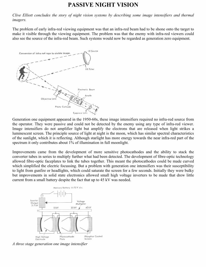
A three-stage image intensifier made by English Electric, below it is a wartime Tabby tube for comparison
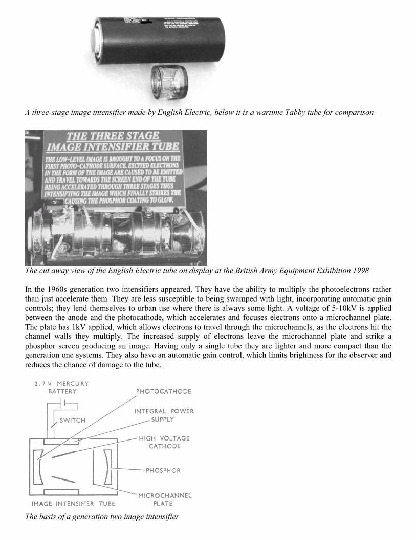
The cut away view of the English Electric tube on display at the British Army Equipment Exhibition 1998
In the 1960s generation two intensifiers appeared. They have the ability to multiply the photoelectrons ratherthan just accelerate them. They are less susceptible to being swamped with light, incorporating automatic gaincontrols; they lend themselves to urban use where there is always some light. A voltage of 5-10kV is appliedbetween the anode and the photocathode, which accelerates and focuses electrons onto a microchannel plate.The plate has 1kV applied, which allows electrons to travel through the microchannels, as the electrons hit thechannel walls they multiply. The increased supply of electrons leave the microchannel plate and strike aphosphor screen producing an image. Having only a single tube they are lighter and more compact than thegeneration one systems. They also have an automatic gain control, which limits brightness for the observer andreduces the chance of damage to the tube.
The basis of a generation two image intensifier
Generation three intensifiers appeared in the 1980s. By using gallium arsenide (GaAs) photocathodes, doublethe sensitivity over the previous generation was achieved.
There are many variations of design, sights for rifles or tank guns need be effective for a reasonable distancewhereas AFV periscopes and observation posts may need a more general appreciation of the immediatesurroundings. But range is not the only consideration, ‘image noise’ and persistence is important. At low levelsof light random background ‘image noise’ causes specs of light to be seen briefly. But light from a target willlast a little longer, by choosing a phosphor screen with maximum persistence it will help the image of the targetto be optimised. Persistence is the glow that you see from the TV screen when it is turned off in a dark room.Similarly image intensifiers continue to glow a little when they are turned off. But there is a trade off becausetasks such as tracking targets and driving require minimum persistence.
British Image IntensifiersIn 1968 the Signals Research and Development Establishment (SRDE) Christchurch unveiled a generation oneimage intensifier weapon sight they had developed. The range stated was 400 metres under “average lightconditions”.
The SRDE assessment model of a weapon sight image intensifier
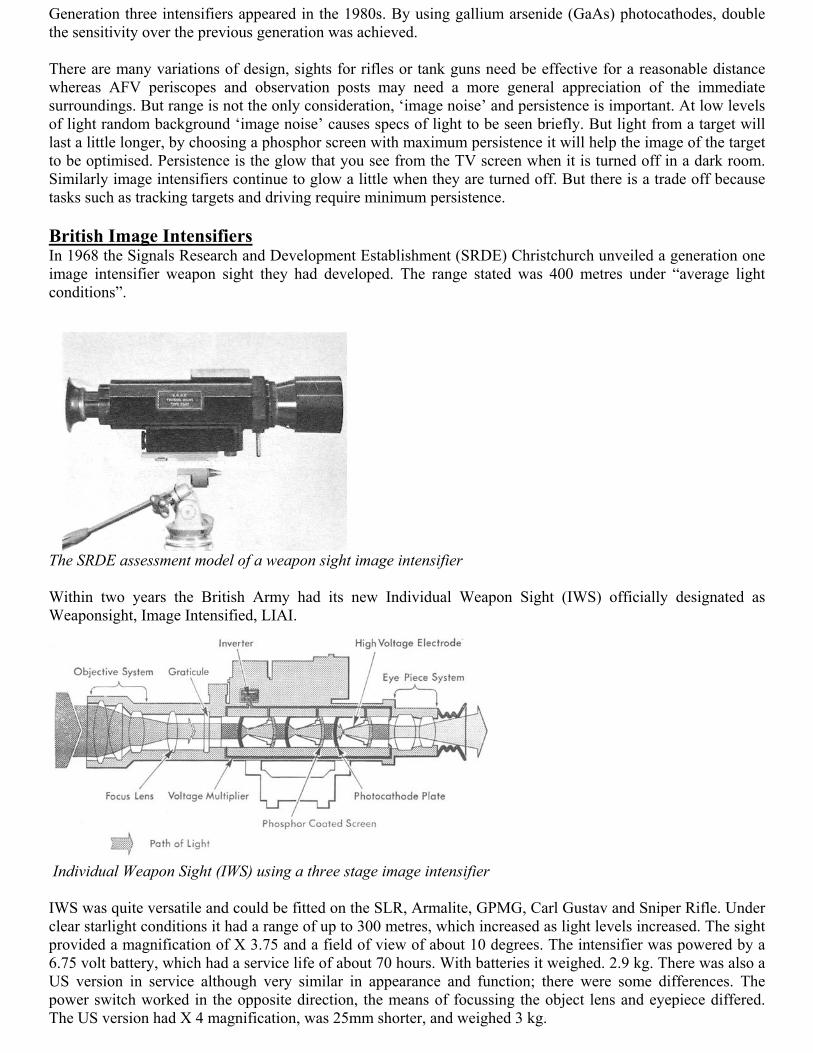
Within two years the British Army had its new Individual Weapon Sight (IWS) officially designated asWeaponsight, Image Intensified, LIAI.
Individual Weapon Sight (IWS) using a three stage image intensifier
IWS was quite versatile and could be fitted on the SLR, Armalite, GPMG, Carl Gustav and Sniper Rifle. Underclear starlight conditions it had a range of up to 300 metres, which increased as light levels increased. The sightprovided a magnification of X 3.75 and a field of view of about 10 degrees. The intensifier was powered by a6.75 volt battery, which had a service life of about 70 hours. With batteries it weighed. 2.9 kg. There was also aUS version in service although very similar in appearance and function; there were some differences. Thepower switch worked in the opposite direction, the means of focussing the object lens and eyepiece differed.The US version had X 4 magnification, was 25mm shorter, and weighed 3 kg.
IWS (UK model) fitted on the GPMG
IWS (UK model) to the left is the objective assembly with lens cover fitted, at the opposite end is the eyepiece.The upper assembly comprises the inverter, with the tube to the right housing the battery, between the twoassemblies is the on/off switch.
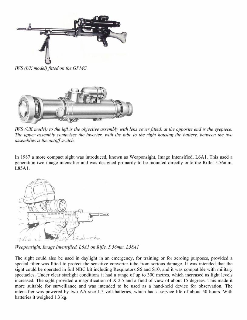
In 1987 a more compact sight was introduced, known as Weaponsight, Image Intensified, L6A1. This used ageneration two image intensifier and was designed primarily to be mounted directly onto the Rifle, 5.56mm,L85A1.
Weaponsight, Image Intensified, L6A1 on Rifle, 5.56mm, L58A1
The sight could also be used in daylight in an emergency, for training or for zeroing purposes, provided aspecial filter was fitted to protect the sensitive converter tube from serious damage. It was intended that thesight could be operated in full NBC kit including Respirators S6 and S10, and it was compatible with militaryspectacles. Under clear starlight conditions it had a range of up to 300 metres, which increased as light levelsincreased. The sight provided a magnification of X 2.5 and a field of view of about 15 degrees. This made itmore suitable for surveillance and was intended to be used as a hand-held device for observation. Theintensifier was powered by two AA-size 1.5 volt batteries, which had a service life of about 50 hours. Withbatteries it weighed 1.3 kg.
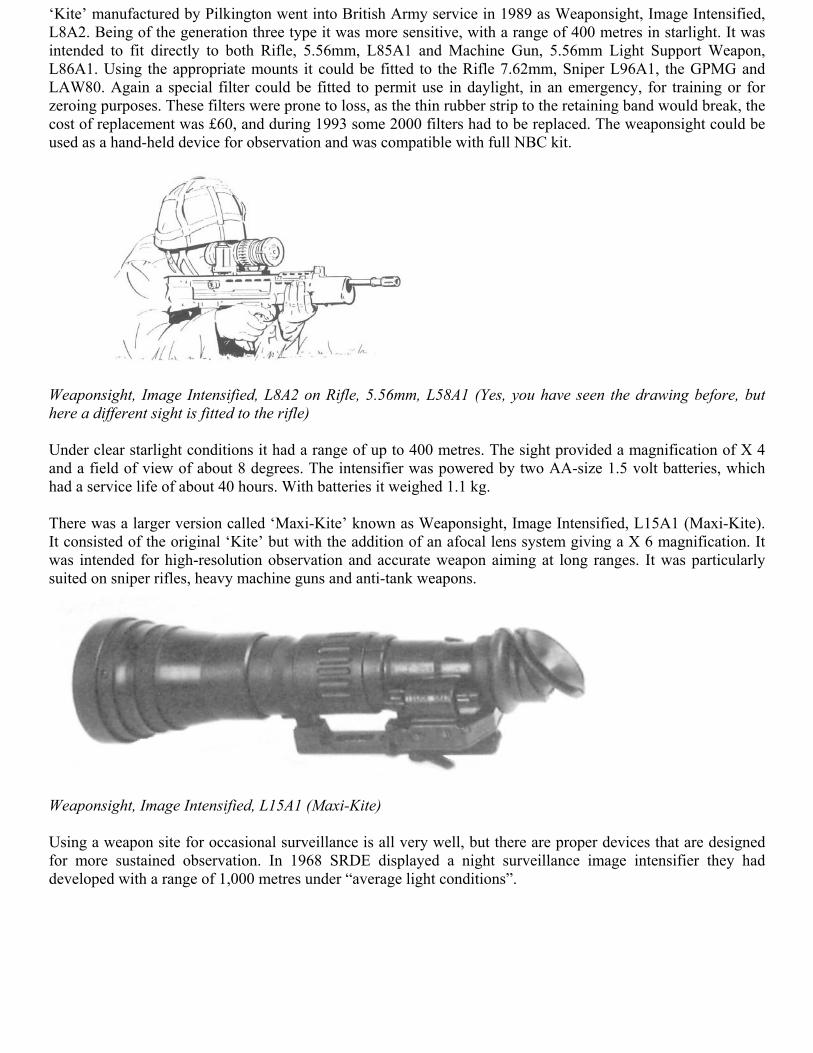
‘Kite’ manufactured by Pilkington went into British Army service in 1989 as Weaponsight, Image Intensified,L8A2. Being of the generation three type it was more sensitive, with a range of 400 metres in starlight. It wasintended to fit directly to both Rifle, 5.56mm, L85A1 and Machine Gun, 5.56mm Light Support Weapon,L86A1. Using the appropriate mounts it could be fitted to the Rifle 7.62mm, Sniper L96A1, the GPMG andLAW80. Again a special filter could be fitted to permit use in daylight, in an emergency, for training or forzeroing purposes. These filters were prone to loss, as the thin rubber strip to the retaining band would break, thecost of replacement was £60, and during 1993 some 2000 filters had to be replaced. The weaponsight could beused as a hand-held device for observation and was compatible with full NBC kit.
Weaponsight, Image Intensified, L8A2 on Rifle, 5.56mm, L58A1 (Yes, you have seen the drawing before, buthere a different sight is fitted to the rifle)
Under clear starlight conditions it had a range of up to 400 metres. The sight provided a magnification of X 4and a field of view of about 8 degrees. The intensifier was powered by two AA-size 1.5 volt batteries, whichhad a service life of about 40 hours. With batteries it weighed 1.1 kg.
There was a larger version called ‘Maxi-Kite’ known as Weaponsight, Image Intensified, L15A1 (Maxi-Kite).It consisted of the original ‘Kite’ but with the addition of an afocal lens system giving a X 6 magnification. Itwas intended for high-resolution observation and accurate weapon aiming at long ranges. It was particularlysuited on sniper rifles, heavy machine guns and anti-tank weapons.
Weaponsight, Image Intensified, L15A1 (Maxi-Kite)
Using a weapon site for occasional surveillance is all very well, but there are proper devices that are designedfor more sustained observation. In 1968 SRDE displayed a night surveillance image intensifier they haddeveloped with a range of 1,000 metres under “average light conditions”.
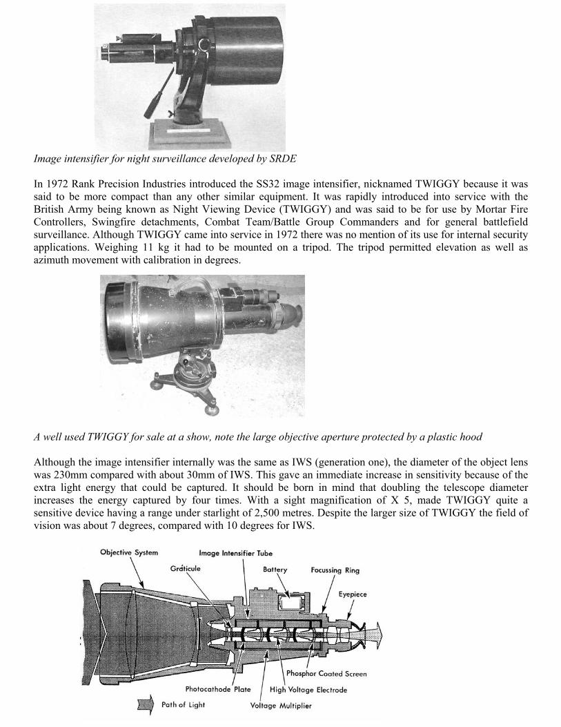
Image intensifier for night surveillance developed by SRDE
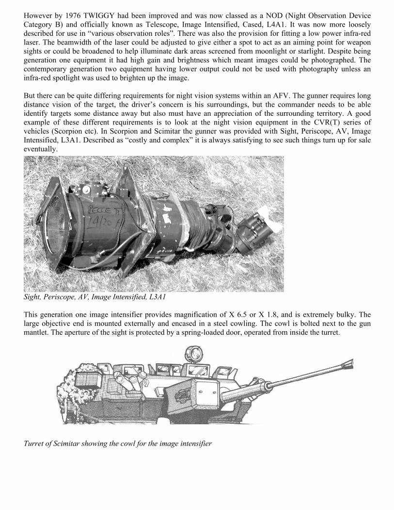
In 1972 Rank Precision Industries introduced the SS32 image intensifier, nicknamed TWIGGY because it wassaid to be more compact than any other similar equipment. It was rapidly introduced into service with theBritish Army being known as Night Viewing Device (TWIGGY) and was said to be for use by Mortar FireControllers, Swingfire detachments, Combat Team/Battle Group Commanders and for general battlefieldsurveillance. Although TWIGGY came into service in 1972 there was no mention of its use for internal securityapplications. Weighing 11 kg it had to be mounted on a tripod. The tripod permitted elevation as well asazimuth movement with calibration in degrees.
A well used TWIGGY for sale at a show, note the large objective aperture protected by a plastic hood
Although the image intensifier internally was the same as IWS (generation one), the diameter of the object lenswas 230mm compared with about 30mm of IWS. This gave an immediate increase in sensitivity because of theextra light energy that could be captured. It should be born in mind that doubling the telescope diameterincreases the energy captured by four times. With a sight magnification of X 5, made TWIGGY quite asensitive device having a range under starlight of 2,500 metres. Despite the larger size of TWIGGY the field ofvision was about 7 degrees, compared with 10 degrees for IWS.
However by 1976 TWIGGY had been improved and was now classed as a NOD (Night Observation DeviceCategory B) and officially known as Telescope, Image Intensified, Cased, L4A1. It was now more looselydescribed for use in “various observation roles”. There was also the provision for fitting a low power infra-redlaser. The beamwidth of the laser could be adjusted to give either a spot to act as an aiming point for weaponsights or could be broadened to help illuminate dark areas screened from moonlight or starlight. Despite beinggeneration one equipment it had high gain and brightness which meant images could be photographed. Thecontemporary generation two equipment having lower output could not be used with photography unless aninfra-red spotlight was used to brighten up the image.
But there can be quite differing requirements for night vision systems within an AFV. The gunner requires longdistance vision of the target, the driver’s concern is his surroundings, but the commander needs to be ableidentify targets some distance away but also must have an appreciation of the surrounding territory. A goodexample of these different requirements is to look at the night vision equipment in the CVR(T) series ofvehicles (Scorpion etc). In Scorpion and Scimitar the gunner was provided with Sight, Periscope, AV, ImageIntensified, L3A1. Described as “costly and complex” it is always satisfying to see such things turn up for saleeventually.
Sight, Periscope, AV, Image Intensified, L3A1
This generation one image intensifier provides magnification of X 6.5 or X 1.8, and is extremely bulky. Thelarge objective end is mounted externally and encased in a steel cowling. The cowl is bolted next to the gunmantlet. The aperture of the sight is protected by a spring-loaded door, operated from inside the turret.
Turret of Scimitar showing the cowl for the image intensifier
The rear section with the eyepiece is mounted on the turret ring. The sight is hinged halfway along to allow theobjective assembly to move with the gun mounting. Note that the previous viewers I have described aremonocular, but the CVR(T) gunner’s viewer is bi-occular i.e. the viewer has two eyepieces but only oneobjective viewer, this lacks the depth of vision achieved in a binocular arrangement which has an objectiveviewing system for each lens.
Sight, Periscope, AV, Image Intensified, L3A1
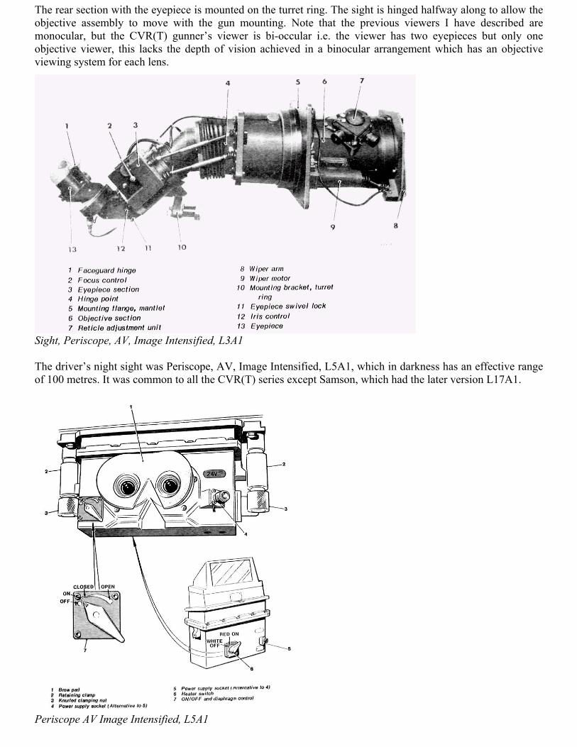
The driver’s night sight was Periscope, AV, Image Intensified, L5A1, which in darkness has an effective rangeof 100 metres. It was common to all the CVR(T) series except Samson, which had the later version L17A1.
Periscope AV Image Intensified, L5A1
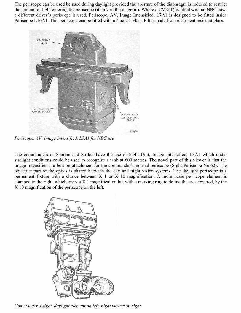
The periscope can be used be used during daylight provided the aperture of the diaphragm is reduced to restrictthe amount of light entering the periscope (item 7 in the diagram). Where a CVR(T) is fitted with an NBC cowla different driver’s periscope is used. Periscope, AV, Image Intensified, L7A1 is designed to be fitted insidePeriscope L16A1. This periscope can be fitted with a Nuclear Flash Filter made from clear heat resistant glass.
Periscope, AV, Image Intensified, L7A1 for NBC use
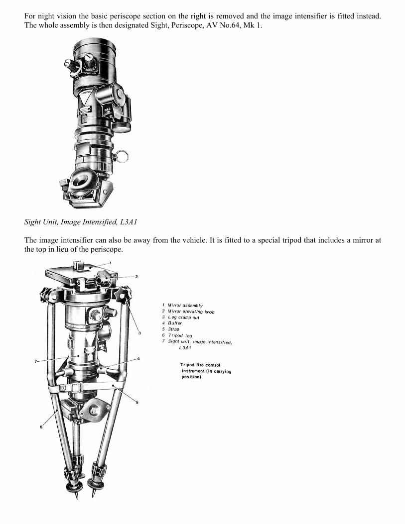
The commanders of Spartan and Striker have the use of Sight Unit, Image Intensified, L3A1 which understarlight conditions could be used to recognise a tank at 600 metres. The novel part of this viewer is that theimage intensifier is a bolt on attachment for the commander’s normal periscope (Sight Periscope No.62). Theobjective part of the optics is shared between the day and night vision systems. The daylight periscope is apermanent fixture with a choice between X 1 or X 10 magnification. A more basic periscope element isclamped to the right, which gives a X 1 magnification but with a marking ring to define the area covered, by theX 10 magnification of the periscope on the left.
Commander’s sight, daylight element on left, night viewer on right
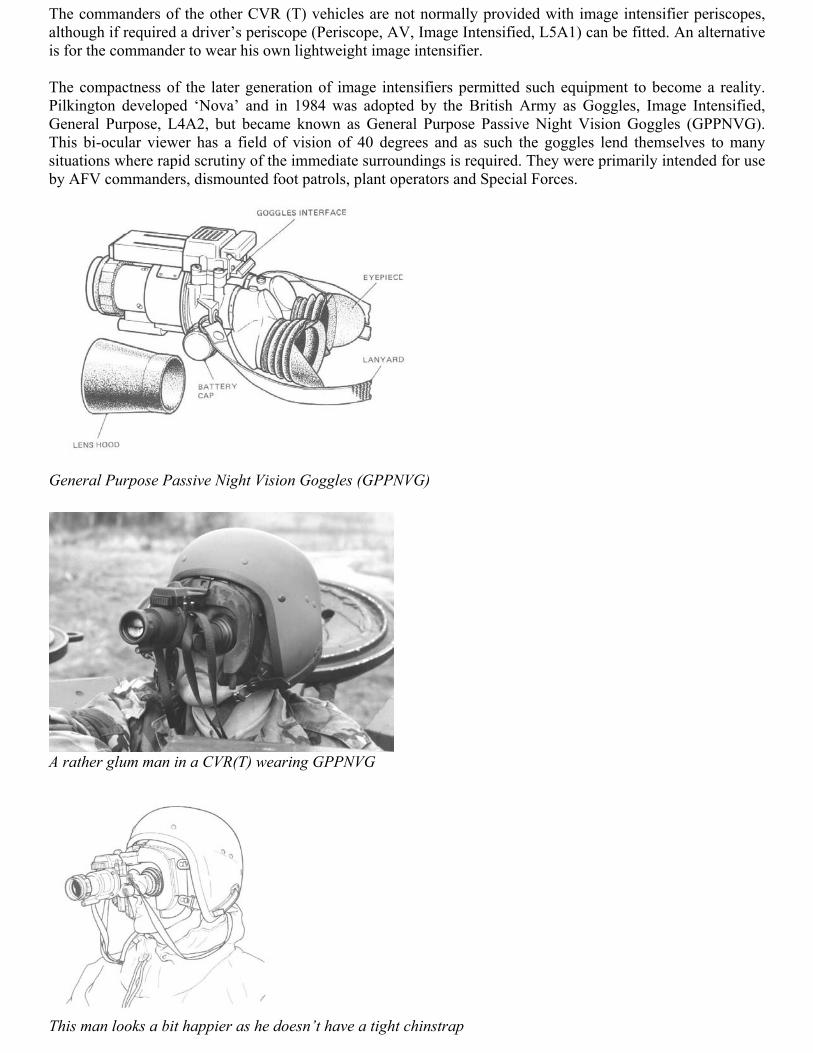
For night vision the basic periscope section on the right is removed and the image intensifier is fitted instead.The whole assembly is then designated Sight, Periscope, AV No.64, Mk 1.
Sight Unit, Image Intensified, L3A1
The image intensifier can also be away from the vehicle. It is fitted to a special tripod that includes a mirror atthe top in lieu of the periscope.
The commanders of the other CVR (T) vehicles are not normally provided with image intensifier periscopes,although if required a driver’s periscope (Periscope, AV, Image Intensified, L5A1) can be fitted. An alternativeis for the commander to wear his own lightweight image intensifier.
The compactness of the later generation of image intensifiers permitted such equipment to become a reality.Pilkington developed ‘Nova’ and in 1984 was adopted by the British Army as Goggles, Image Intensified,General Purpose, L4A2, but became known as General Purpose Passive Night Vision Goggles (GPPNVG).This bi-ocular viewer has a field of vision of 40 degrees and as such the goggles lend themselves to manysituations where rapid scrutiny of the immediate surroundings is required. They were primarily intended for useby AFV commanders, dismounted foot patrols, plant operators and Special Forces.
General Purpose Passive Night Vision Goggles (GPPNVG)
A rather glum man in a CVR(T) wearing GPPNVG
This man looks a bit happier as he doesn’t have a tight chinstrap
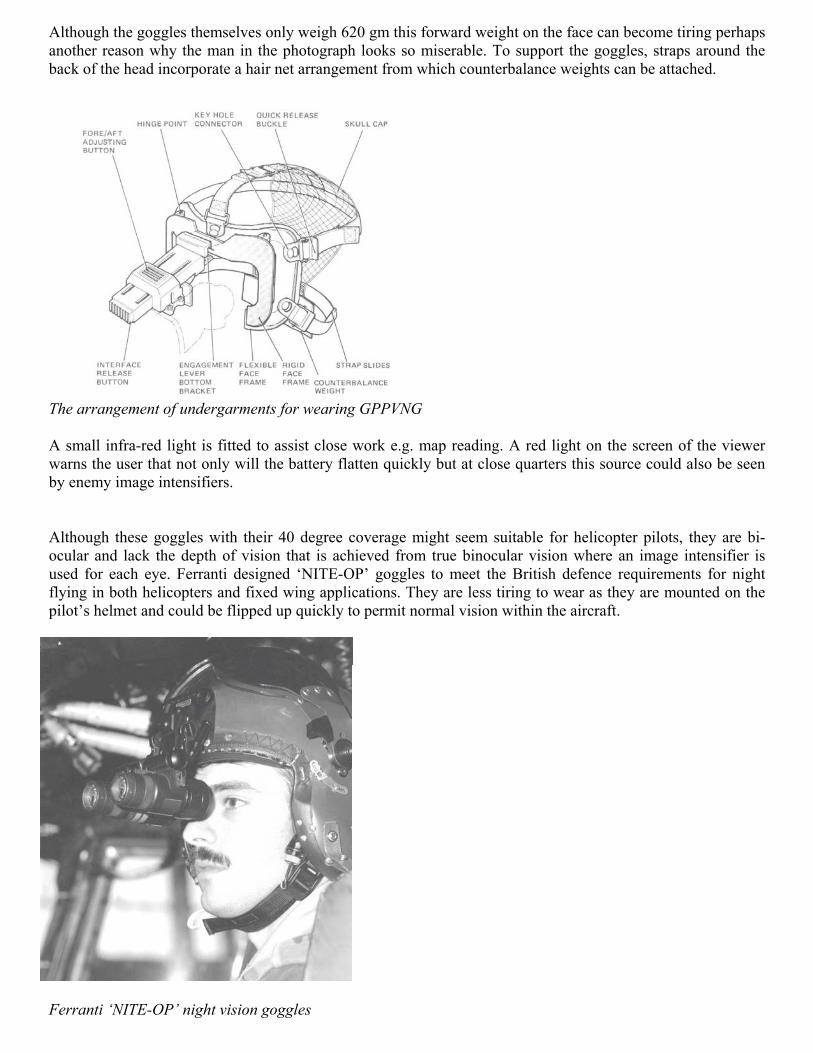
Although the goggles themselves only weigh 620 gm this forward weight on the face can become tiring perhapsanother reason why the man in the photograph looks so miserable. To support the goggles, straps around theback of the head incorporate a hair net arrangement from which counterbalance weights can be attached.
The arrangement of undergarments for wearing GPPVNG
A small infra-red light is fitted to assist close work e.g. map reading. A red light on the screen of the viewerwarns the user that not only will the battery flatten quickly but at close quarters this source could also be seenby enemy image intensifiers.
Although these goggles with their 40 degree coverage might seem suitable for helicopter pilots, they are bi-ocular and lack the depth of vision that is achieved from true binocular vision where an image intensifier isused for each eye. Ferranti designed ‘NITE-OP’ goggles to meet the British defence requirements for nightflying in both helicopters and fixed wing applications. They are less tiring to wear as they are mounted on thepilot’s helmet and could be flipped up quickly to permit normal vision within the aircraft.
Ferranti ‘NITE-OP’ night vision goggles
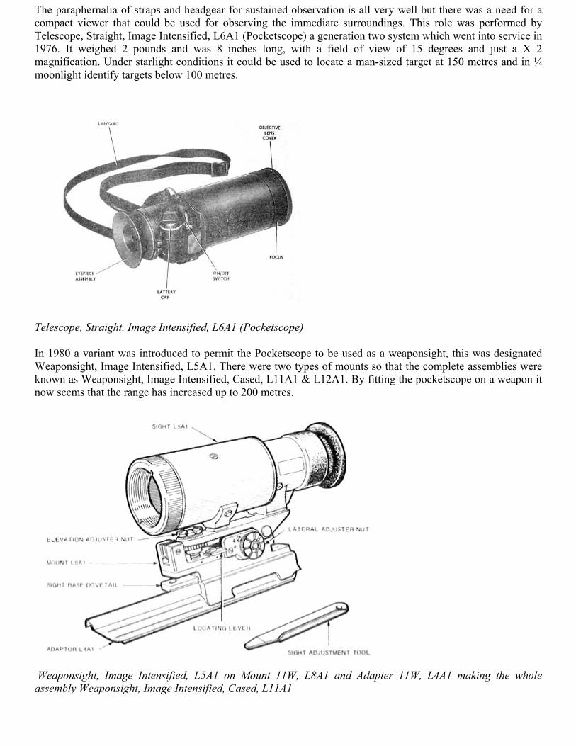
The paraphernalia of straps and headgear for sustained observation is all very well but there was a need for acompact viewer that could be used for observing the immediate surroundings. This role was performed byTelescope, Straight, Image Intensified, L6A1 (Pocketscope) a generation two system which went into service in1976. It weighed 2 pounds and was 8 inches long, with a field of view of 15 degrees and just a X 2magnification. Under starlight conditions it could be used to locate a man-sized target at 150 metres and in ¼moonlight identify targets below 100 metres.
Telescope, Straight, Image Intensified, L6A1 (Pocketscope)
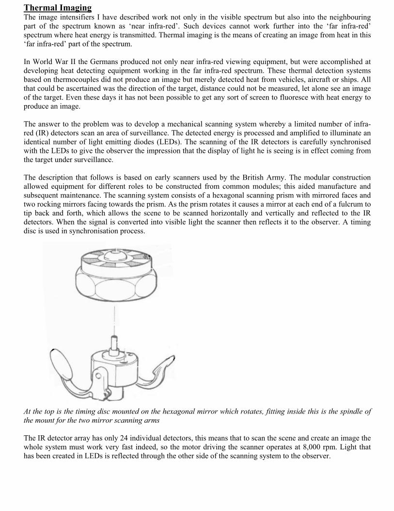
In 1980 a variant was introduced to permit the Pocketscope to be used as a weaponsight, this was designatedWeaponsight, Image Intensified, L5A1. There were two types of mounts so that the complete assemblies wereknown as Weaponsight, Image Intensified, Cased, L11A1 & L12A1. By fitting the pocketscope on a weapon itnow seems that the range has increased up to 200 metres.
Weaponsight, Image Intensified, L5A1 on Mount 11W, L8A1 and Adapter 11W, L4A1 making the wholeassembly Weaponsight, Image Intensified, Cased, L11A1
Thermal ImagingThe image intensifiers I have described work not only in the visible spectrum but also into the neighbouringpart of the spectrum known as ‘near infra-red’. Such devices cannot work further into the ‘far infra-red’spectrum where heat energy is transmitted. Thermal imaging is the means of creating an image from heat in this‘far infra-red’ part of the spectrum.
In World War II the Germans produced not only near infra-red viewing equipment, but were accomplished atdeveloping heat detecting equipment working in the far infra-red spectrum. These thermal detection systemsbased on thermocouples did not produce an image but merely detected heat from vehicles, aircraft or ships. Allthat could be ascertained was the direction of the target, distance could not be measured, let alone see an imageof the target. Even these days it has not been possible to get any sort of screen to fluoresce with heat energy toproduce an image.
The answer to the problem was to develop a mechanical scanning system whereby a limited number of infra-red (IR) detectors scan an area of surveillance. The detected energy is processed and amplified to illuminate anidentical number of light emitting diodes (LEDs). The scanning of the IR detectors is carefully synchronisedwith the LEDs to give the observer the impression that the display of light he is seeing is in effect coming fromthe target under surveillance.
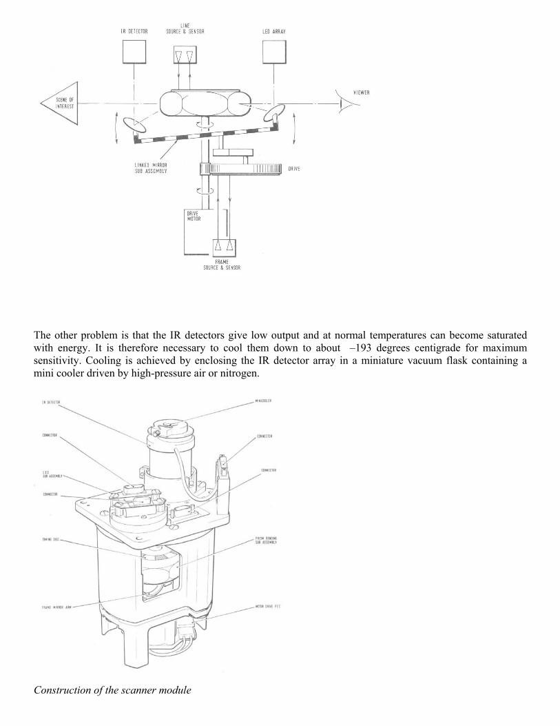
The description that follows is based on early scanners used by the British Army. The modular constructionallowed equipment for different roles to be constructed from common modules; this aided manufacture andsubsequent maintenance. The scanning system consists of a hexagonal scanning prism with mirrored faces andtwo rocking mirrors facing towards the prism. As the prism rotates it causes a mirror at each end of a fulcrum totip back and forth, which allows the scene to be scanned horizontally and vertically and reflected to the IRdetectors. When the signal is converted into visible light the scanner then reflects it to the observer. A timingdisc is used in synchronisation process.
At the top is the timing disc mounted on the hexagonal mirror which rotates, fitting inside this is the spindle ofthe mount for the two mirror scanning arms
The IR detector array has only 24 individual detectors, this means that to scan the scene and create an image thewhole system must work very fast indeed, so the motor driving the scanner operates at 8,000 rpm. Light thathas been created in LEDs is reflected through the other side of the scanning system to the observer.
The other problem is that the IR detectors give low output and at normal temperatures can become saturatedwith energy. It is therefore necessary to cool them down to about –193 degrees centigrade for maximumsensitivity. Cooling is achieved by enclosing the IR detector array in a miniature vacuum flask containing amini cooler driven by high-pressure air or nitrogen.
Construction of the scanner module
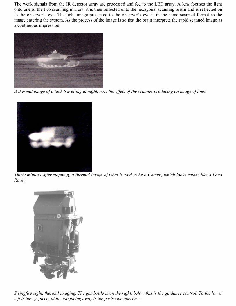
The weak signals from the IR detector array are processed and fed to the LED array. A lens focuses the lightonto one of the two scanning mirrors, it is then reflected onto the hexagonal scanning prism and is reflected onto the observer’s eye. The light image presented to the observer’s eye is in the same scanned format as theimage entering the system. As the process of the image is so fast the brain interprets the rapid scanned image asa continuous impression.
A thermal image of a tank travelling at night, note the effect of the scanner producing an image of lines
Thirty minutes after stopping, a thermal image of what is said to be a Champ, which looks rather like a LandRover
Swingfire sight, thermal imaging. The gas bottle is on the right, below this is the guidance control. To the lowerleft is the eyepiece; at the top facing away is the periscope aperture.
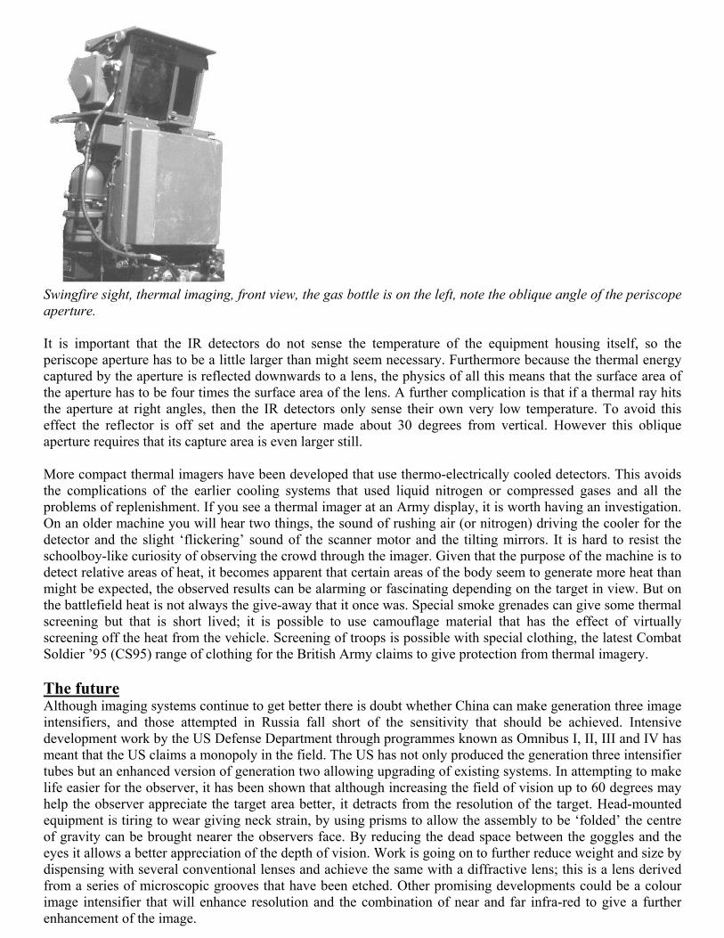
Swingfire sight, thermal imaging, front view, the gas bottle is on the left, note the oblique angle of the periscopeaperture.
It is important that the IR detectors do not sense the temperature of the equipment housing itself, so theperiscope aperture has to be a little larger than might seem necessary. Furthermore because the thermal energycaptured by the aperture is reflected downwards to a lens, the physics of all this means that the surface area ofthe aperture has to be four times the surface area of the lens. A further complication is that if a thermal ray hitsthe aperture at right angles, then the IR detectors only sense their own very low temperature. To avoid thiseffect the reflector is off set and the aperture made about 30 degrees from vertical. However this obliqueaperture requires that its capture area is even larger still.
More compact thermal imagers have been developed that use thermo-electrically cooled detectors. This avoidsthe complications of the earlier cooling systems that used liquid nitrogen or compressed gases and all theproblems of replenishment. If you see a thermal imager at an Army display, it is worth having an investigation.On an older machine you will hear two things, the sound of rushing air (or nitrogen) driving the cooler for thedetector and the slight ‘flickering’ sound of the scanner motor and the tilting mirrors. It is hard to resist theschoolboy-like curiosity of observing the crowd through the imager. Given that the purpose of the machine is todetect relative areas of heat, it becomes apparent that certain areas of the body seem to generate more heat thanmight be expected, the observed results can be alarming or fascinating depending on the target in view. But onthe battlefield heat is not always the give-away that it once was. Special smoke grenades can give some thermalscreening but that is short lived; it is possible to use camouflage material that has the effect of virtuallyscreening off the heat from the vehicle. Screening of troops is possible with special clothing, the latest CombatSoldier ’95 (CS95) range of clothing for the British Army claims to give protection from thermal imagery.
The futureAlthough imaging systems continue to get better there is doubt whether China can make generation three imageintensifiers, and those attempted in Russia fall short of the sensitivity that should be achieved. Intensivedevelopment work by the US Defense Department through programmes known as Omnibus I, II, III and IV hasmeant that the US claims a monopoly in the field. The US has not only produced the generation three intensifiertubes but an enhanced version of generation two allowing upgrading of existing systems. In attempting to makelife easier for the observer, it has been shown that although increasing the field of vision up to 60 degrees mayhelp the observer appreciate the target area better, it detracts from the resolution of the target. Head-mountedequipment is tiring to wear giving neck strain, by using prisms to allow the assembly to be ‘folded’ the centreof gravity can be brought nearer the observers face. By reducing the dead space between the goggles and theeyes it allows a better appreciation of the depth of vision. Work is going on to further reduce weight and size bydispensing with several conventional lenses and achieve the same with a diffractive lens; this is a lens derivedfrom a series of microscopic grooves that have been etched. Other promising developments could be a colourimage intensifier that will enhance resolution and the combination of near and far infra-red to give a furtherenhancement of the image.
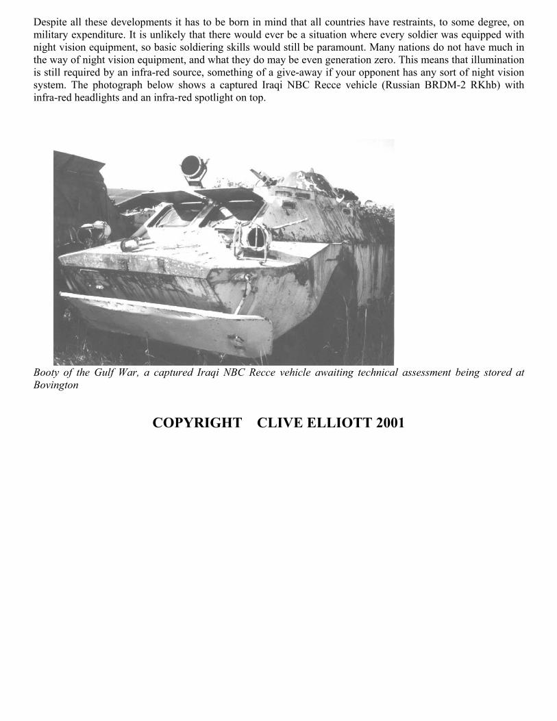
Despite all these developments it has to be born in mind that all countries have restraints, to some degree, onmilitary expenditure. It is unlikely that there would ever be a situation where every soldier was equipped withnight vision equipment, so basic soldiering skills would still be paramount. Many nations do not have much inthe way of night vision equipment, and what they do may be even generation zero. This means that illuminationis still required by an infra-red source, something of a give-away if your opponent has any sort of night visionsystem. The photograph below shows a captured Iraqi NBC Recce vehicle (Russian BRDM-2 RKhb) withinfra-red headlights and an infra-red spotlight on top.
Booty of the Gulf War, a captured Iraqi NBC Recce vehicle awaiting technical assessment being stored atBovington
COPYRIGHT CLIVE ELLIOTT 2001