Embed Size (px)
Citation preview

Figure 1: Sketch of Daventry experiment.
Figure 2: Klein Heidelberg receiver andChain Home radars.
Introduction
Since radar had been recognized by the military as a means to detect enemy air or naval targets at extended ranges, its vulnerability to localisation due to the fact that it could not work without transmitting energy was well understood. Although at the beginning of the XXth century there were no such threats as anti-radiation-missiles, a radar location could be determined by receiving the typical radar signals and using triangulation. The jamming and destruction of radar systems were threats that developed later. The advantage of silent operation without revealing ones position was obvious and thus a seed for the desire for passive radar was already planted in the early days of radar.
Passive radar before and during WW2
The history of passive radar measurements with the aim of detecting aircraft targets dates back to 1935, when Sir Robert Watson-Watt conducted a bi-static experiment using the illumination from the shortwave (49 m wavelength) BBC Empire transmitter at Daventry to detect a Heyford bomber aircraft at short distance (8 km) [1, 2]. The Heyford was a slow aircraft that fi st fl w in 1930. For the purposes of the test however, with a wing span of 75 feet, it did provide quite a large object to ’aim at’ in the sky. Furthermore, the
dimensions of the Hayford equated nearly to a half wavelength of the source signal. The test was to be carried out in a fi ld outside the town of Weedon, near Daventry. Fig. 1 shows a sketch of the Daventry experiment. The Heyford was fl wn on a path between Weedon and the BBC transmitter at Daventry. The detection equipment consisted of a rather large receiver which was fi ted with an oscilloscope, furnished by The National Physical Laboratory, and was tuned to the wavelength of the BBC Empire transmitter at Daventry. The pilot of the Heyford, Flight Lieutenant R. S. Blucke, took off from Farnborough, climbed to 6,000 feet and started to fl the course on his fl ght plan making passes at various altitudes. Robert Watson-Watt and his assistant Arnold Wilkins tuned their radio receiver to the frequency of the BBC transmitter at Daventry. As the Heyford bomber fl w overhead, the signal of the transmitter which was being received and displayed on the oscilloscope, began to fl ctuate, indicating that a variable and measurable amount of radio signal was being refl cted from the passing Heyford aircraft. The men in the
STO-EN-SET-243 1 - 1
PUBLIC RELEASE
PUBLIC RELEASE
Passive Coherent Locator History and Fundamentals

Figure 3: Klein Heidelberg antenna.
van watched as the signal indicated the aircraft in their vicinity; they were able to track it for some 8 miles. Subsequent to the successful demonstration, a new radar research establishment, the Bawdsey Research Station, was founded under the Air Ministry and Sir Robert Watson-Watt became its Superintendent in 1936. Later, his research led to the installation of a chain of radars along the south and east coast of England, known as the Chain Home radars [3]. While the Chain Home radars were active radars operating with a transmitting power of 350 kW (later 750 kW) at a frequency of 20-30 MHz, on the German side passive radars were installed along the continental Channel coast. Since 1943, the German ”Klein Heidelberg” receivers located near the Channel coast line exploited the emissions of the British ”Chain Home” radars to detect in-coming aircraft [4]. These were the fi st operational passive radars. Resistance to the British jammers was the main advantage of the passive Klein Heidelberg receivers over the German active radars Freya, Mammut, Wasserman and Würzburg. After preliminary trials at ”mount couple” between Calais and Boulogne 4 Klein Heidelberg receivers were set into operation in summer 1944 at Oostvoorne, den Haan, Boulogne and Abbeville. Fig. 2 shows the location of the Oostvoorne station and the illuminating Chain Home radars. A picture of the Klein Heidelberg antenna based on a 40 m Wasserman S tower is shown in Fig. 3. The main antenna consisted of 18 dipole elements in front of a refl ctor plane positioned in 3 column arrays of 6 elements, each. It spanned a beam-width of 45 degrees and provided an angular measurement accuracy of about 5 degrees. An additional dipole antenna at 15 m height received the direct transmitted signal.
New interest in passive radar after WW2
With the invention of the duplexer in 1936, which permitted the rapid development of the operationally more convenient, single-site, monostatic radar, interest in passive radar was temporarily lost. Radar development turned towards low probability of intercept (LPI) radars and the investigation of electronic counter counter measures (ECCM) to cope with jamming. In the 1980s several European countries developed interest in ”passive location”, which primarily referred to passive emitter tracking (PET) and passive jammer location, but also included a passive radar receiver concept hitchhiking on the emission of a conventional airport surveillance radar (ASR). This concept included the so called pulse chasing principle, which requires the passive receiver to follow with its beam the pulse emitted through the rotating antenna of the active illuminator radar. As the transmitted pulse travels along the transmit beam direction at the speed of light, pulse chasing requires extremely fast beam steering on the receiver site, or, alternatively multiple receiver beams (fan beam, see Fig. 4),
1 - 2 STO-EN-SET-243
PUBLIC RELEASE
PUBLIC RELEASE

Figure 4: Pulse Chasing with Fan Beam
which can be steered at a somewhat slower speed. Though being very ambitious, the latter approach seemed more realistic at that time. A further revival of passive covert radar (PCR), or equivalently passive coherent location (PCL), occurred in the 1990s, when the NATO defence research group (DRG) launched a study on passive and noise radar, which was concluded by a symposium [5]. In addition to the pulse-chasing principle, which applies to the exploitation of non-cooperative pulsed radar signals as illumination, broadcast transmitters were discovered as potential sources for PCR. The new motivation for passive radar was, in addition to its covertness, the system’s inherent anti-stealth capability. Since stealth technology primarily aims at the reduction of an aircrafts radar cross section (RCS) with respect to mono-static radars at operational radar frequencies from L- to X-band, the bi- or multi-static geometry of passive radars and their predominant VHF/UHF illuminators successfully counter stealth. PCL studies were conducted at UCL, where Griff ths and Long investigated the use of analogue TV transmissions from Crystal Palace for the detection of aircraft targets, [6]. Additionally Howland utilised the analogue TV video carrier, again from the venerable Crystal Palace transmitter, to detect and track air-liners to ranges of up to 260 km. These studies demonstrated the feasibility of the principle of PCL technology. At the same time Thales in France obtained a patent on a method which exploits the spectral shift of the TV-carrier and the line synchronisation pulses of a moving target echo versus the direct signal for passive target detection ranging. A demonstration of passive radar target detection using the illumination of a Russian type P18 VHF-surveillance radar was conducted under the name of PARADE (Passive Radar Demonstration) in 2001 by FGAN-FHR in co-operation with the Hungarian Technology agency. As a further source of illumination being available in almost all parts of the world FM-radio signals were exploited in many PCR system designs. The fi st commercial PCR prototype using FM-radio broadcast emissions was developed by Lockheed-Martin [7] and is referred to as ”Silent Sentry” (see Fig. 4), thus underlining the sensors covertness. In France, a small company C&T (Communcation et Téléphonie) led by Jean-Philippe Brunet developed a system called Occiu [8], which consisted of an 8-element antenna array, an off-the-shelf computer, sophisticated signal processing and a mission planning software ”Aneth”.
STO-EN-SET-243 1 - 3
PUBLIC RELEASE
PUBLIC RELEASE

Figure 7: PARADE multi-band PCL (courtesy of AIRBUS D&S).
Figure 4: Silent Sentry 3 setup (courtesy Figure 5: Thales HA100 antenna (courtesy of Lockheed-Martin [7] of Thales).
Figure 6: AULOS PCL-system (courtesy of Selex-ES).
Other European industries like Thales and EADS among others became interested in the new sensor approach. In retrospect, Occiu can be considered the predecessor to HA100 by Thales (see Fig. 5). The name HA100 standing for Homeland Alerter with about 100 km detection range suggests the role foreseen for this type of sensor. Later, other industries like SELEX (Sytem AULOS, Fig. 6), Cassidian (System PARADE, Fig. 7) and ERA (Fig. 8) as well as research institutions like NC3A [9], Warsaw University of Technology, WUT, (System PaRaDe, Fig. 9) and ONERA joined in with experimental systems or demonstrators.
Fraunhofer FHR during that period had developed and operated a number of experimental systems like CORA, PETRA and DELIA [10], leading to a demonstrator for DVB-T-PCL, LORA11 [11] (Fig. 10), the use of which was shared with FFI of Norway. The handling of vast amounts of data at reasonable processing times was facilitated by technological development. Direct RF-signal digitisation, applying the ”software defi ed radar” principle further supported the applicability of passive radar for military and civil security purposes.
1 - 4 STO-EN-SET-243
PUBLIC RELEASE
PUBLIC RELEASE

<- Figure 8: ERA 6-element FM-PCL-System.
Figure 9: PaRaDe antenna (courtesy of Technical University of Warsaw).
Figure 11: Sketch of the PCL geometry.
Passive Radar Principle of Operation The expression ”passive radar systems” indicates a class of bistatic radar systems that do not send a dedicated electromagnetic signal, but instead they exploit electromagnetic signals emitted by other sources for other purposes. Such sources are usually referred to as ”illuminators of opportunity” (IOs), and they can be other radars, communication systems, broadcast systems for public utility and so. The principle of operation of passive radar is based on cross-correlating the signal received directly from a transmitter with its refl ctions from a target. A typical geometry is sketched in Fig. 10. The PCL receiver measures the time difference of arrival (TDOA) between the direct signal and the refl cted echo. From TDOA measurement, the bistatic range measurement is retrieved considering the electromagnetic wave propagation speed. Cross-correlation
between direct reference signal and refl ct echoes is performed in the two-dimensional range-Doppler domain. This means that different possible Doppler modulated replicas of the direct signal are cross-correlated with the echo signals. As a consequence, a PCL radar system is also able to estimate the bistatic Doppler frequency (or, which is equivalent, the bistatic range rate). It is easy
to show that a bistatic range measurement locates the target onto an ellipsoid that has
Figure 10: LORA11 DVB-T PCL-System of FHR and FFI with linear array antenna.
STO-EN-SET-243 1 - 5
PUBLIC RELEASE
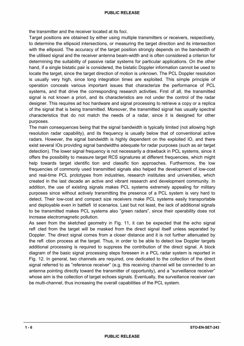
the transmitter and the receiver located at its foci. Target positions are obtained by either using multiple transmitters or receivers, respectively, to determine the ellipsoid intersections, or measuring the target direction and its intersection with the ellipsoid. The accuracy of the target position strongly depends on the bandwidth of the utilised signal and the receiver antenna beam-width and is often considered a criterion for determining the suitability of passive radar systems for particular applications. On the other hand, if a single bistatic pair is considered, the bistatic Doppler information cannot be used to locate the target, since the target direction of motion is unknown. The PCL Doppler resolution is usually very high, since long integration times are exploited. This simple principle of operation conceals various important issues that characterize the performance of PCL systems, and that drive the corresponding research activities. First of all, the transmitted signal is not known a priori, and its characteristics are not under the control of the radar designer. This requires ad hoc hardware and signal processing to retrieve a copy or a replica of the signal that is being transmitted. Moreover, the transmitted signal has usually spectral characteristics that do not match the needs of a radar, since it is designed for other purposes. The main consequences being that the signal bandwidth is typically limited (not allowing high resolution radar capability), and its frequency is usually below that of conventional active radars. However, the signal bandwidth is highly dependent on the exploited IO, and there exist several IOs providing signal bandwidths adequate for radar purposes (such as air target detection). The lower signal frequency is not necessarily a drawback in PCL systems, since it offers the possibility to measure target RCS signatures at different frequencies, which might help towards target identific tion and classific tion approaches. Furthermore, the low frequencies of commonly used transmitted signals also helped the development of low-cost and real-time PCL prototypes from industries, research institutes and universities, which created in the last decade an active and vibrant research and development community. In addition, the use of existing signals makes PCL systems extremely appealing for military purposes since without actively transmitting the presence of a PCL system is very hard to detect. Their low-cost and compact size receivers make PCL systems easily transportable and deployable even in battlefi ld scenarios. Last but not least, the lack of additional signals to be transmitted makes PCL systems also ”green radars”, since their operability does not increase electromagnetic pollution. As seen from the sketched geometry in Fig. 11, it can be expected that the echo signal refl cted from the target will be masked from the direct signal itself unless separated by Doppler. The direct signal comes from a closer distance and it is not further attenuated by the refl ction process at the target. Thus, in order to be able to detect low Doppler targets additional processing is required to suppress the contribution of the direct signal. A block diagram of the basic signal processing steps foreseen in a PCL radar system is reported in Fig. 12. In general, two channels are required, one dedicated to the collection of the direct signal referred to as ”reference receiver” (e.g. this receiving channel will be connected to an antenna pointing directly toward the transmitter of opportunity), and a ”surveillance receiver” whose aim is the collection of target echoes signals. Eventually, the surveillance receiver can be multi-channel, thus increasing the overall capabilities of the PCL system.
1 - 6 STO-EN-SET-243
PUBLIC RELEASE
PUBLIC RELEASE

Figure 12: Basic PCL signal processing.
Figure 13: Basic PCL signal processing using digital transmitter.
On the other hand, the reference receiver is usually single channel. It is clear that a dedicated reference receiver channel is needed because the transmitted signal is not known a priori. Basically it is important to receive the reference signal as clean as possible, which generally requires a line-of-sight to the transmitter and a highly directional antenna in order to avoid multipath. This is in particular a basic requirement when analogue (broadcast) signals are exploited, which do not offer the possibility to reconstruct the transmitted signal from signal synchronization features. Fig. 13 shows the general processing chain, which starts with cross-correlating the reference channel with the surveillance channel and it ends with tracking detected targets in the Cartesian domain. One of the most important steps in the processing chain is the suppression of the direct signal since its correlation sidelobes might mask weak target echoes. The direct signal suppression can be achieved by f ltering the received signal spatially, which means to point a minimum of the receiver antenna diagram towards the transmitter or in the time domain, which means to subtract coherently the contribution of the direct signal from the surveillance channel echoes. In the following sections, deeper insights into these approaches are presented.
This basic processing scheme can be refi ed if a digital transmission of opportunity is exploited. In fact, as mentioned above, the direct signal is likely to be the strongest signal contribution also in the ”surveillance channel”. As a consequence, after proper synchronization and by knowing the transmission standard, it is possible to decode the transmitted stream of bits, and then re-code this stream to reconstruct the original transmitted signal. This operation can be done using a single channel surveillance receiver, with signific nt reduction of costs and system complexity. If this second approach is followed, the block diagram in Fig. 12 would be modifi d to the one depicted in Fig. 13. In both cases, a cleaned version of the transmitted signal is used to remove from the surveillance channel the direct signal contribution (together with eventual multi-paths components, see later dedicated sections in this report). This step is labeled ”disturbance cancellation”. After direct signal removal, the ”cleaned” surveillance signal is cross-correlated to the range-Doppler domain with the ”cleaned” reference signal, thus producing one range-Doppler map per coherent
integration interval (CPI). Over the range-Doppler maps, target detection is performed (for instance resorting to constant false alarm rate, CFAR, approaches). Detections collected from multiple CPIs can be further processed to produce tracks of detected targets. Target tracking can be performed in the range- Doppler domain, or in Cartesian coordinates, if a mean of target geo-localization is available. It can be shown, that a two-stage tracking (both
STO-EN-SET-243 1 - 7
PUBLIC RELEASE
PUBLIC RELEASE

in range-Doppler and in Cartesian coordinates) might drastically reduce the resulting number of false alarms.
Overview of illuminators of opportunity
In the following we will classify the transmitters of opportunity, which can serve as illuminators for Passive Radar according to their location, even though there are other criteria, which one might choose, like signal modulation or purpose of transmission.
To the family of terrestrial IOs belong:
• other radars: for example used for air traff c control (ATC) or for maritime coastalmonitoring;
• mobile communication systems: specific lly base stations for global system for mobilecommunication (GSM), universal mobile telecommunication system (UMTS), long termevolution (LTE); access points for wireless fi elity (WiFi), worldwide interoperability formicrowave access (WiMAX), HiperLAN;
• broadcast systems for public utility: frequency modulation (FM) and digital audiobroadcast (DAB) radio (analog and digital, respectively); analog and digital videobroadcast terrestrial (DVB-T, also known as digital TV);
To the family of space borne IOs belong:
• other radars: for example used for Earth monitoring and remote sensing applications;• broadcast systems for public utility: such as digital video broadcast satellite (DVB-S, also
known as digital satellite TV), and its handheld variation (DVB-SH);• mobile communication systems: like Globalstar, Iridium, and Orbcomm;• geolocalization system: transmitters like global positioning system (GPS), global
navigation satellite system (GLONASS), and the future GALILEO;
Among these different possibilities, a good IO for PCL should provide a reliable continuous transmitted signal over time, with a strong equivalent isotropically radiated power (EIRP), possibly over a wide area. For this last reason, other radars are usually excluded from the analysis. Moreover, as briefl discussed before, the transmitted signal characteristics should be as uniform as possible. For this reason, in general digital transmissions are favorable with respect to analog ones. An example is represented by FM radio. FM radio has been largely exploited for PCL purposes in the fi st years of XXIst century, given its wide availability and its reasonable transmit power. However, FM radio modulation is analog, which means that the effective instantaneous signal bandwidth is highly dependent on the program content being broadcasted. Specific lly, rock music seems to be most advantageous due to a comparably large constant bandwidth, while oral contributions like news are the least favorable (an explanatory example of differently resulting PCL performance for different transmitted FM radio signals can be observed comparing the ambiguity functions in Figs. 7.10 and 7.11 in [10]). Careful selection of the transmitter to be used is therefore required for optimum performance. For this reason, the exploitation of FM radio started rapidly to diminish as other digital broadcast services entered in operation, such as DAB and DVB-T. DAB and DVB-T (namely terrestrial digital radio and television, respectively) use an orthogonal frequency division modulation (OFDM) scheme, which guarantees constant signal features, namely constant bandwidth and characteristics of the auto-ambiguity function. However, digital modulation schemes also present drawbacks mainly related to periodicities in the signal structure.
1 - 8 STO-EN-SET-243
PUBLIC RELEASE
PUBLIC RELEASE
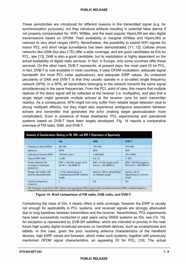
These periodicities are introduced for different reasons in the transmitted signal (e.g. for synchronization purposes), but they introduce artifacts resulting in potential false alarms if not properly compensated for. WiFi, WiMax, and the least popular HiperLAN are also digital transmissions based on OFDM. Their availability is marginal (WiMax and HiperLAN) or reduced to very short ranges (WiFi). Nevertheless, the possibility to exploit WiFi signals for indoor PCL and short range surveillance has been demonstrated, [11, 12]. Cellular phone networks like GSM (but also LTE) offer a wide coverage, and are good candidates as IOs for PCL, see [13]. DAB is also a good candidate, but its exploitation is highly dependent on the actual availability of digital radio services. In fact, in Europe, only some countries offer these services. On the other hand, DVB-T represents, at present days, the most used IO for PCL. In fact, DVB-T is now available in most countries, it uses OFDM modulation, adequate signal bandwidth (for most PCL radar applications), and adequate EIRP values. An undesired peculiarity of DAB and DVB-T is that they usually operate in a so-called single frequency network (SFN). In a SFN, all transmitters belonging to the network transmit the same signal simultaneously in the same frequencies. From the PCL point of view, this means that multiple replicas of the direct signal will be collected at the receiver (i.e. multipaths), and also that a single target might generate multiple echoes at the receiver (one for each transmitter nearby). As a consequence, SFN might not only suffer from reliable target detection (due to strong multipath effects), but they might also experience ambiguous association between echoes and transmitter that generated the echo (making target geolocalization more complicated). Even in presence of these drawbacks, PCL experimental and operational systems based on DVB-T have been largely developed. Fig. 14 reports a comparative overview of FM radio, DAB, and DVB-T.
Figure 14: Brief comparison of FM radio, DAB radio, and DVB-T.
Considering the class of IOs, it clearly offers a wide coverage, however the EIRP is usually not enough for applicability in PCL systems, and received signals are strongly attenuated due to long baselines between transmitters and the receiver. Nevertheless, PCL experiments have been successfully conducted in past years using GNSS systems as IOs, see [14, 15]. An exception is represented by DVB-SH satellites, which are intended to provide in the near future high quality digital broadcast services on handheld devices, such as smartphones and tablets. In this case, given the poor receiving antenna characteristics of the handheld devices, high EIRP values are foreseen, which make such systems, together with previously mentioned OFDM signal characteristics, an appealing IO for PCL, [16]. The actual
STO-EN-SET-243 1 - 9
PUBLIC RELEASE
PUBLIC RELEASE

Fig. 15: Illustration of the elevation beam pattern tilted below the horizontal.
Fig. 16: Representation of antenna elevation pattern in polar coordinates.
commercial success of these services will likely drive their availability (or not) in the near future. Recent fast emerging concurrent standards like LTE might obscure DVB-SH.
FM, DVB-T and DAB antenna elevation characteristics Among the primary objectives in broadcast engineering is achieving wide-area coverage with adequate fi ld intensity so that users can receive the transmissions of interest. The ”users” in terms of broadcast engineering, usually refer to ground-based receivers for such services as FM radio, TV, DAB, DVB-T, GSM, etc. In the case of commonly used illuminators of opportunity for passive radar purposes, namely FM, DAB and DVB-T, the fi ld strength produced by a station depends, inter alia, on ERP, antenna heights, local terrain and tropospheric scattering conditions. The antenna systems usually consist of several individual radiating bays fed as a phased array. Their radiation characteristics concentrate the energy in the horizontal plane towards the population to be served, minimising the radiation out into space. Minimising the radiation out into space (i.e. beyond the horizon) requires the vertical plane radiation pattern to be tilted slightly below the horizontal. This is a common procedure in broadcast engineering and is referred to as beam-tilt. The beam-tilt principle is illustrated in Fig. 15. Fig. 16 is a representation of an antenna elevation pattern in polar coordinates. Point 1 in Fig. 16 indicates the peak of the beam at the horizon (the illustration does not depict beam-tilt).
The maximum ERP occurs at the peak of the beam where the beamwidth is narrowest. Point 2 refers to of the maximum fi ld pattern (equivalent to the -3 dB beamwidth). The strength of the mainlobe falls off increasingly as the angle from the centre of the beam increases. It is conventional to consider the -3dB beamwidth to determine the size of the antennas frontal area (aperture). Fig. 17 depicts the antenna mainlobe illuminating a number of possible target altitude levels. The levels chosen are 1 km, 2 km, 5 km, 10 km and 15 km as targets of interest could potentially occupy some or all of this altitude range. The corresponding
distances from the transmitter, i.e. a km, b km, c km, d km and e km can be approximated using the identities: a = 1 km/tan(θ 3dB ); b = 2 km/tan(θ 3dB ); c = 5 km/tan(θ 3dB ); d = 10 km/tan(θ 3dB ) and e = 15 km/tan(θ 3dB ). Note that the identities assume that the transmitter height is negligible in comparison to the target altitudes, and is thus not considered.
1 - 10 STO-EN-SET-243
PUBLIC RELEASE
PUBLIC RELEASE

•••
STO-EN-SET-243 1 - 11
PUBLIC RELEASE
PUBLIC RELEASE

References [1] S. S. Swords, Technical History of the Beginnings of Radar. History of Technology,
Institution of Engineering and Technology, 1986. [2] “http://www.andrewphotographic.co.uk/g8gmu9a.htm.” [3] J. Gough, Watching the skies: a history of ground radar for the air defence of the
United Kingdom by the Royal Air Force from 1946 to 1975. HMSO, 1993. [4] H. D. Griff ths, “Radar system lecture notes.” UCL, 2009. [5] NATO DRG Symposium on Passive and noise radar. [6] H. Griff ths and N. Long, “Television-based bistatic radar”, IEE Proceedings
Communications, Radar and Signal Processing, vol. 133, pp. 649–657, December 1986.
[7] “http://www.mobileradar.org/documents/silentsentry.pdf.” [8] J. Dupont, “AIR and COSMOS no.1984,” May 2005. [9] P. E. Howland, D. Maksimiuk, and G. Reitsma, “FM radio based bistatic radar”, IEE
Proceedings - Radar, Sonar and Navigation, vol. 152, June 2005. [10] H. Kuschel et al.; Experimental passive radar systems using digital illuminators
(DAB/DVB-T) IRS2007, Cologne, Germany [11] G. Bournaka, A. Baruzzi, J. Heckenbach, H. Kuschel, Experimental Validation of
Beamforming Techniques for Localization of Moving Target in Passive Radar 2015 IEEE Radar Conference (RadarCon), pp. 1710–1713, May 2015
[12] F. Colone, P. Falcone, C. Bongioanni, and P. Lombardo, “WiFi-based passive bistatic radar: Data processing schemes and experimental results,” IEEE Transactions on Aerospace and Electronic Systems, vol. 48, pp. 1061–1079, APRIL 2012.
[13] R. Zemmari, M. Broetje, G. Battistello, and U. Nickel, “GSM passive coherent location system: performance prediction and measurement evaluation,” IET Proceedings Radar, Sonar and Navigation, vol. 8, pp. 94–105, February 2014.
[14] X. He, T. Zeng, and M. Cherniakov, “Signal detectability in SS-BSAR with GNSS non cooperative transmitter,” IEE Proceedings - Radar, Sonar and Navigation, vol. 152, pp. 124–132, June 2005.
[15] M. Cherniakov, R. Saini, R. Zuo, and M. Antoniou, “Space-surface bistatic synthetic aperture radar with global navigation satellite system transmitter of opportunity experimental results,” IET Radar, Sonar Navigation, vol. 1, pp. 447–458, Dec 2007.
Fig. 17: Difference between SFN and MFN, from [19]
1 - 12 STO-EN-SET-243
PUBLIC RELEASE
PUBLIC RELEASE