Embed Size (px)
Citation preview

International Journal of Fluid Power Vol. 5(2). pp. 43-56, 2004.
PASSIVE BILATERAL TELEOPERATION OF A HYDRAULIC ACTUATOR USING AN ELECTROHYDRAULIC PASSIVE VALVE
Perry Y. Li and Kailash Krishnaswamy
Department of Mechanical Engineering, University of Minnesota, 111 Church St. SE, Minneapolis, MN 55455, USA [email protected], [email protected]
Abstract
A passive control scheme for the bilateral teleoperation of an electrohydraulic actuator and a motorized joystick is proposed. The overall system enables a human operating a motorized joystick to feel as if he is manipulating a rigid mechanical tool with which the work environment is also in contact. By ensuring that the closed loop system behaves like a passive two port device, safety and stability when coupled to other systems are improved. The control scheme is developed by first using previously developed active feedback to passify a four way proportional directional control valve, and then by the design of an intrinsically passive teleoperation controller. The coordination error between the joystick and the hydraulic actuator converges to zero for sufficiently low manipulation bandwidth. Experimental results verify the characteristics of the control scheme.
Keywords: hydraulic teleoperation, bilateral teleoperation, passive control, passivity, electrohydraulic actuator
1 Introduction
Many hydraulic systems are required to touch and contact their physical environments in applications such as earth-digging, the transport of materials etc. Of these, many are also controlled by human operators on-site via control levers or joysticks. A typical example is a construction worker operating a hydraulic boom-and-bucket to perform an earth digging task. These systems are two-port devices that simultaneously interact and form closed loop systems with both the human operator and the physical environment. It is critical that these systems remain stable and can safely interact with a broad range of environments and human operators. In addition, these systems must be natural and easy for the human operator to control.
Both the safety and the human friendliness aspects of these applications can be enhanced if the system can be shown to be passive. Roughly speaking, a passive system behaves as if it does not generate energy, but only stores, dissipates and releases it. A passive system is inherently safer than a non-passive system because the
amount of energy that it can impart to the environment is limited. The well known passivity theorem (Vidyasagar, 1993) ensures that a passive system can interact stably with any strictly passive system which includes all physical objects and environments that do not contain an energy source. Even human operators have been shown to be indistinguishable from a passive system (Hogan, 1989). Notice that this interaction stability property cannot be guaranteed by merely stable systems, as stable systems can be destabilized when physically coupled with another stable system.
The inherent safety that passive systems afford was exploited in electromechanical machines that interact with humans such as smart exercise machines (Li and Horowitz, 1997), bilateral teleoperated manipulators (Anderson and Spong, 1989; Lee and Li, 2003; Lee and Li, 2002), haptic interface (Hannaford and Ryu, 2002), Cobots (Colgate et al, 1996), coding natural robot autonomous behavior (Li and Horowitz, 1999), and robot contour following with and without force control (Li and Horowitz, 2001; Li and Li, 2000). The first application of

International Journal of Fluid Power Vol. 5(2). pp. 43-56, 2004.
the passivity concept to hydraulic systems seems to be (Li, 2000).
Previous attempts to improve operation productivity and safety of hydraulic construction equipment from a controls point of view include human remote control with the use of vision feedback investigated in (Chen et al, 1996); supervisory control approaches for autonomous operation investigated in (Chen et al, 1996; Cannon and Singh, 2000) in which the soil / machine interactions are explicitly modeled and taken into account; and artificial intelligence approach for autonomous operation as investigated in (Bradley and Seward, 1998). Teleoperation approaches in which direct human control is assumed, were studied both in Europe (Starzewski and Skibiniewski, 1989; Luengo and Barrientos, 1998) and by the University of British Columbia (UBC) group in Canada (Parker et al, 1993; Salcudean et al, 1999; Salcudean et al, 1998; Salcudean et al, 1997; Tafazoli et al, 1996; Tafazoli et al, 1999). The control goal undertaken in the pioneering work on the teleoperation of excavators by Lawrence, Salcudean and co-workers at UBC is to install an ideal transparent mapping between human / machine interaction, and the machine / environment interaction. Their approaches are mainly based on impedance control (especially hybrid impedance control) with the assumption that the dynamics of the hydraulics can be abstracted after the use of simple low level control. Because ideal transparency is required in their problem formulation, some knowledge of the environment impedances has to be assumed in this approach. These impedances cannot be precisely known in reality. Such control schemes, unfortunately, cannot guarantee passivity. In most teleoperation scenarios, it is necessary to develop a controller that apart from other objectives, also guarantees the stability of operator-machine-work environment interaction. Our research approach to guaranteeing this interaction stability with a broad class of environments is by ensuring that the machine is passive. This is in contrast to previous approaches in which passivity is not guaranteed.
In this paper, a control methodology for a bilateral teleoperated hydraulic actuator and a force feedback joystick is proposed. The objective is to control the telemanipulation system so that it appears to the work environment and the human operator as if they are both interacting with a common virtual passive rigid mechanical tool after appropriate power and kinematic scalings. The control
scheme enables the human to be kinesthetically and energetically connected to its work environment. For example, it allows a human operating an excavator to feel as if he is manipulating a spade. The control objectives in (Li and Lee, 2003; Lee and Li, 2002) are similar except that they are concerned with electromechanical, rather than hydraulic machines. The proposed control scheme ensures that the system has the passivity property without abstracting away the valve dynamics. An impediment to the development of passive control schemes for electrohydraulic actuators is that, unlike mechanical and electromechanical systems, electrohydraulic valves are not inherently passive. This difficulty was overcome in (Li, 2000) in which passification methods are proposed, via either structural modification or active feedback control, to transform a single-stage four way proportional directional control valve into a passive two port device. Similar approach was later developed for two-stage valves (Krishnaswamy and Li, 2002), and generalized to the passification of other mechatronic devices (Li and Ngwompo, 2002).
In the present paper, we develop a teleoperation control system based on a valve that has been passified using the active feedback passification method in (Li, 2000). The teleoperation controller, which controls both the passified valve and the motorized joystick, is designed to be intrinsically passive with respect to an appropriate supply rate so that the overall system is always passive, and which, for sufficiently slow manipulation, achieves asymptotic coordination of the joystick and the hydraulic actuator.
The rest of this paper is organized as follows. The key concepts of passivity are reviewed in section II. The models for the various subsystems are described in section III. Section IV reviews the technique for passifying the four way proportional directional control valve, which is the first step in the control design process. Section V describes the passive teleoperation control law. Implementation results are given in Section VI. Section VII contains concluding remarks.
2 Preliminaries
Consider a dynamical system with input u and output y. A supply rate for a system can be defined to be any function of the input/output
International Journal of Fluid Power Vol. 5(2). pp. 43-56, 2004.
pair s:(u, y) → s(u, y) ∈ R that is Lle integrable in time. Following (Willems, 1972), a system is said to be dissipative or passive with respect to the supply rate s(u, y) if, for a given initial condition, there exists a constant c so that for all time t and for all input u( ⋅ ),
t 2
0( ( ), ( ))τ τ τ− ≤∫ s u y d c (1)
For physical systems, useful supply rates are those associated with power input into the system. For most physical systems, u(t) and y(t) are the complementary effort/flow or flow/effort variable pairs. For such systems, the supply rate formed by the inner product of the effort (e.g. force, pressure, voltage) and the flow (e.g. velocity, flow, current) variables quantifies the physical power input to the dynamical system. The inequality 1 then, means that the net energy that can be extracted from a passive system is finite and bounded by the initial energy of the dynamical system, c2.
For a two-port system that interacts with two environments via the input/output variables (u1, y1), and (u2, y2) at the two respective ports, a system is said to be passive with a power scaling ρ > 0, if
t T T
1 1 2 20
2[ ( ) ( ) ( ) ( )]ρ τ τ τ τ τ+ ≥−∫ u y u y d c
(2) Here, the supply rate for the two-port
system s((u1, y1), (u2, y2)) consists of the sum of the power input at port 1 scaled by ρ and the power input at port 2. For the teleoperator system, port 1 can be the human interaction port, and port 2 is the work environment port. Then, ρ > 1 and ρ < 1 correspond to the human power
amplification and attenuation factors respectively.
To demonstrate that a system is passive with respect to a supply rate s(u, y), it suffices to define a storage function W(x), which is a positive scalar function of the state x, with the property that:
d( ( )) ( , )
dW x t s u y
t≤
Integrating with respect to time, gives
∫ −≥t
xWdyus0
))0((),( τ
For physical systems, the total energies of
the systems are good candidates for storage functions.
3 System Modelling and Control Objectives
The hydraulic teleoperation system consists of three physical subsystems, a direct acting four way proportional directional flow control valve (together with a pump that supplies a constant supply pressure sP ), a one degree of freedom double ended hydraulic actuator, and a motorized joystick. The teleoperation controller, usually implemented on a computer, is to be developed later. The configuration of the teleoperated system is shown in Fig. 1.The model of each hardware subsystem is now described.
Fig. 1: The teleoperated system consists of 1) a motorized force feedback joystick, 2) a teleoperation
controller, 3) a passified valve with an embedded power supply, 4) a hydraulic actuator.

International Journal of Fluid Power Vol. 5(2). pp. 43-56, 2004.
PB PA
P0
= 0Ps
Xv
(from pump)(to tank)
B A Q1Q2 Fig. 2: Four way, three land proportional
directional control valve
3.1 Single Stage Control Valve Model
Consider a symmetric, matched, critically centred four way proportional directional control valve which is shown in Fig. 2. Assume that the valve is supplied by a constant pressure source, and is connected to a flow-conserving device, such as a double-ended actuator or a motor so that the output and return flows are the same. Let xv be the spool displacement, and
BAL PPP −= is the load pressure, i.e. the differential pressure between the two flow ports connected to the valve. Then the output flow QL is given by (Merritt, 1967):
L v L
vdv s L v L s
vh
vdv s L v L s
vh
( , )
, sgn( )
:
, sgn( )
ρ
ρ
− <
=
− − + ≥
⎧ ⎫⎪ ⎪⎪ ⎪⎨ ⎬⎪ ⎪⎪ ⎪⎩ ⎭
Q x P
xCwx P P x P P
x
xCwx P P x P P
x
(3)
where Cd > 0 is the orifice discharge coefficient, ρh > 0 is the fluid density, w > 0 is the gradient of the orifice area with respect to the spool position, Ps is the constant supply pressure..In normal operation, ⎪PL⎪ < Ps so only the first case statement in Eq. 3 is commonly used. Following (Li, 2000), Eq. 3 can be rewritten as:
L v L q v t v L L( , ) ( , )= −Q x P K x K x P P (4) where
sq d
hρ=
PK C w (5)
1
Lt v L v L
0 L
( , ) ( , )d∂
= ⋅∂∫Q
K x P x P l lP
(6)
are the no-load flow gain, and the mean slope of the PL - QL curve between the zero load pressure point and the operating load pressure point respectively. In Eq. 6, l is a dummy integration variable. Notice that Kt(xv,PL) is non-negative for all xv and PL. Note that from Eq. 4, that Kt(xv,PL)PL is the difference between the actual load flow QL (xv,PL) and that predicted by the no-load flow gain. Eq. 4 means that the valve can be interpreted to comprise an ideal modulated flow source Kqxv, and a shunt (bleed-off) conductance Kt(xv,PL). For further details, please see (Li, 2000).
For the purpose of the present paper, we can identify from Eq. 3, a load adjusted flow gain q v L(sgn( ), )K x P , namely,
q v L
vds L v L s
vh
vds L v L s
vh
(sgn( ), )
, sgn( )
, sgn( )
ρ
ρ
− <
=
− − + ≥
⎧ ⎫⎪ ⎪⎪ ⎪⎨ ⎬⎪ ⎪⎪ ⎪⎩ ⎭
K x P
xCw P P x P P
x
xCw P P x P P
x
(7) such that
L q v L v(sgn( ), )=Q K x P x (8)
Notice that q v L(sgn( ), )K x P depends only on sgn(xv) but not on xv itself; and as sgn(xv)PL increases from 0→Ps, q v L(sgn( ), )K x P decreases from q 0K > to 0. Therefore, whenever |PL| < Ps, it is possible to choose an appropriate desired spool position xv
d to achieve any desired flow rate QL
d (less than the saturated flow limit): d
d Lv d
q L L(sgn( ), )=
Qx
K Q P (9)
where sgn(xvd) is chosen to be the sign of QL
d. Let the dynamics of the spool be given by:
vε =&&x u (10) where ε is the mass of the spool, u is the control force. In an actual direct acting proportional control valve, in addition to the control input, u may include also the centring spring forces, as well as the steady state spring and transient damping forces manifested by the steady state and transient flow forces. One way to consider Eq. 10 is that it represents the resulting dynamics when these spool forces have been cancelled out.

International Journal of Fluid Power Vol. 5(2). pp. 43-56, 2004.
However, as will be apparent, since the passification control law to be developed relies on terms that are of the same forms as these spring and damping forces, these forces can in fact be considered part of the passification control law, and thus do not need to be cancelled out deliberately. In actual implementation, these forces were not cancelled.
As shown in (Li, 2000), the proportional directional control valve is not passive as a one port device with respect to the hydraulic power s(PL,QL) := -PLQL as the supply rate for any constant xv ≠ 0. Intuitively, this is because the valve will be delivering hydraulic energy whenever the load pressure sgn(xv)PL is smaller than the hydraulic supply pressure Ps. It will be shown in section IV, that via control, the valve can be passified to be a passive two port device.
3.2 Hydraulic Actuator Model
The hydraulic actuator is assumed to be a double ended cylinder with annulus area Ap. Further, assuming incompressible fluid flow within the actuator and no leakage between actuator chambers, the actuator kinematic and force balance equations are given by:
p p L L env
p
1;= =&A x Q P F
A (11)
where xp is the actuator displacement, Fenv is the environment force acting on the piston, QL is the flow through the actuator and PL is the load pressure which is the differential pressure between the actuator chambers. If QL is provided by the valve as in Eq. 8, then:
q v LLp v
p p
(sgn( ), )= =&
K x PQx x
A A (12)
By taking the product of the load pressure PL and the load flow rate QL given in Eq. 11, it can be seen that the actuator is passive with respect to the supply rate:
piston env p L L env p L L(( , ), ( , )) := − +& &s F x Q P F x P Q (13)
since piston env p L L(( , ), ( , )) 0s F x Q P ≡& .
3.3 Motorized Joystick Model
The motorized joystick dynamics are given by:
q q q= +&&M q F T (14) where Mq > 0 is the joystick inertia, Fq is the control (motor) force, and Tq is the force supplied by the operator. Using the kinetic energy
2
joystick q
1( , )
2W q q M q=& &
as the candidate storage function, and by differentiating it, it is easy to show that the motorized joystick is passive with respect to the supply rate,
joystick q q q q(( , ), ( , )) :s F q T q F q T q= +& & & & which is the total power input.
3.4 Control Objectives
Given a kinematic scaling α ∈ R and a power scaling ρ > 0, our goal is to control the hydraulic actuator and the motorized joystick so that 1. the joystick position and the hydraulic actuator piston position are coordinated. Thus, we want the coordination error E(t) to converge to 0:
( ) ( ) ( )p: 0α= − →E t q t x t (15) 2. the closed loop control system shown in Fig. 1 is passive with respect to the supply rate:
total q env p q env p(( , ), ( , )) : ρ= −& & & &s T q F x T q F x (16)
where q &T q is the power input by the human operator, env p− &F x is the power input by the work environment, and ρ > 1 is the power scaling factor.
4 Passification of the Control Valve
As mentioned in Section I, the first step in the control design is to passify the valve. In (Li, 2000), two methodologies are proposed to render the valve a passive two port system, with respect to a supply rate that consists of the hydraulic power and a supply function related to the command. One approach is based on structural modification, and the other is based on active feedback control. The following theorem from (Li, 2000) pertains to the latter which is the approach utilized in the present paper. Please refer to (Li 2000) for further interpretations and details. Theorem 1 (Li, 2000) Let Fx be the auxiliary, exogenous command input to the valve, and let
v x L
1: ( )= − −&z x F AP
B
Consider the control law for the spool given by

International Journal of Fluid Power Vol. 5(2). pp. 43-56, 2004.
v L v
x L 2
x
ˆ ˆ( ) ( ) ( ) sgn( ( ))
γ
ε
= − − −
+ − −
+
⎡ ⎤⎣ ⎦
&
& &
u Bx AP Bx
F t AP t g t z tBF
(17) where B > 0 is a damping coefficient, A > 0 is the pressure feedback gain,γ > 0 is a positive spring rate, and symbol ^ denotes the best estimate of the argument )(⋅
If )(2 tg in Eq.17 is defined so that
2
x L x L
( ) sgn( ( ))
ˆ ˆ( ) ( ) ( ( ) ( ))
>
− − −⎡ ⎤⎣ ⎦& & & &
g t z t
F t AP t F t AP t (18)
then the critically lapped four way two-port valve is passive with respect to the supply rate
q
L x v x v L L(( , ), ) : [ ]= + −K
s P F x F x P QA
(19)
which consists of a “command power” term and a hydraulic power output term. Proof: We define the following storage function,
q 2 2
v
1
2 2
KW Bx z
A
ε
γ= +
⎡ ⎤⎢ ⎥⎣ ⎦
which consists of “energies” associated with the states xv and z. Differentiating this storage function, we get:
q q 2
x v L q v
q
x v L L
( )γ
≤ − −
≤ −
&K K B
W F x P K x zA A
KF x P Q
A
(20)
where the first inequality is due to the definition of g2(t), and the second inequality is derived using the fact that,
q 2 2
t v L L( , ) 0K B
z K x P PAγ
− − ≤
as q 0K B
Aγ> and so is Kt(xv,PL). The passivity
property of the valve is obtained by integrating Eq. 20.
Remark 0 B, A and γ can be arbitrarily
defined as long as they are positive. However, they affect the apparent power scaling of the passified valve between the command port and they hydraulic port (given by Kq / A) as well as the valve bandwidth (see Remark 4).
Remark 1 The passified valve in Theorem 1 can be thought of as a two-port device with the command port variables Fx, xv, and the output port variables PL and QL. PLQL is the hydraulic power output, and Fxxv can be considered a fictitious command power. In this case, the 2-port device has associated with it a power scaling factor of Kq / A.
Remark 2 Notice that the spool control force u in Eq.17 contains a spring term -γBxv, and a damping term vBx− & . Moreover, recall that flow rate is monotonic with respect to spool opening, and steady flow forces are proportional to the flow rate squared, and inversely proportional to the orifice area; transient flow forces are proportional to the rate of change of flow rate. Thus the steady flow force can be modeled as a spring force and the transient flow force (approximately) as a damping force acting on the spool1. Hence, the spring forces due to the centering spring and steady flow force can be (approximately) subsumed in the spring term -γBxv. Similarly, the damping forces due to viscous damping and transient flow forces can be subsumed in the damping term vBx− & in Eq. 17.
Remark 3 The passification control requires estimates of the time derivatives of the load pressure PL and of the auxiliary valve command Fx. These can be computed from the pressure chamber dynamics and from the teleoperation control (to be designed). In implementation, these estimates are obtained by direct backward numerical differentiation. The error in this estimate is taken care of, while preserving passivity, by the robustness term (g2(t) sgn(z(t))) in Eq. 17, but at the expense of added dissipation.
Remark 4 When the estimate of the term x L( ) ( )F t AP t−& & is accurate, the valve behaviour is
given by the transfer function:
]/)/([/
)()()(
εγεε
BBssBBs
sAPsFsx
Lx
v
+++
=−
(21) where s is the Laplace variable. Thus, for low frequency operation, the passified valve dynamics are given by:
x L sp v− =F AP K x (22)
1Strictly speaking, modelling the transient flow force as a damping force is an approximation due to its dependence on the rate of change of pressure. This dependence is however traditionally considered insignificant to the valve dynamics (see Merritt, 1967 p.104 for a discussion).

International Journal of Fluid Power Vol. 5(2). pp. 43-56, 2004.
where Ksp := γB is the equivalent spring rate. If the dynamics of the passified valve are designed to be critically damped, the repeated pole will be given by –B/(2ε), so that the bandwidth within which the low frequency approximation is appropriate will be B/(2ε). The subsequent teleoperation controller design will be based on the low frequency approximation of the passive vale dynamics as given by Eq. 22. Thus, for good performance, the bandwidth of operation should be less than B / (2ε) rad/s.
From Eq. 20, we see that the dissipation term is –KqB/(Aγ)⋅z2. This is an artifact of the specific passification method in Theorem 1. For steady state operation, γ xv ≈ z, so this dissipation
term is given by q 2
sp v
KK x
A− . Thus, the
equivalent spring rate Ksp contributes to the
dissipation in the passified valve. As will be shown later, this is reflected in the haptics property of the teleoperator.
Remark 5 Although the passification control law Eq. 17 – Eq. 19 is developed based on the assumption that the valve is connected to a flow conserving device, a similar passification control law can be similarly obtained when the valve’s outlet and return flows are in a constant and known ratio (e.g. when connecting to a single ended cylinder). This can be done by first re-deriving the equivalent flow / pressure relation Eq. 3 for the matched symmetric 4-way valve for this case, and by defining the load pressure PL to be the flow ratio weighed pressure difference between the two ports.
yB2
yA1
yA2 uB
1
uA2
uA2 yA
2uB1 yB
1− + γ2
2uA1 yA
1uA
2 yA2+ γ
1 dt >= −c2
uB2
uA1 yA
1yB
2uB2
dt >= −e2
uA1
yB1 System BSystem A
:=
=:
dt >= −d
+ γ1
γ2
Fig. 3: Interconnection of two passive two-port systems with compatible supply rates is a passive two-port system
Notice, that the motorized joystick, hydraulic actuator, and the passive valves are all passive two-port devices. The following lemma shows that interconnection of passive two-port subsystems with compatible supply rates result in passive systems. Lemma 1 Consider the two two-port systems A and B with respective port variables (u1
A, y1A),
(u2A, y2
A), and (u1B, y1
B), (u2B, y2
B) (see Fig. 3). Suppose that system A is passive with respect to the supply rate
1 1 2 2 1 1 2 2
A A A A A A A 1 A A(( , ), ( , ))S u y u y u y u yγ= ⋅ + ⋅ and system B is passive with respect to the supply rate
1 1 2 2 1 1 2 2B B B B B B B 2 B B(( , ), ( , ))S u y u y u y u yγ= − ⋅ + ⋅
where γ1 > 0, γ2 > 0. Then, the interconnection given by u2
A:=y1B, u1
B:=y2A is passive with
respect to the supply rate: 1 1 2 2 1 1 2 2
AB A A B B A A 1 2 B B(( , ), ( , )) :S u y u y u y u yγ γ= ⋅ + ⋅ Proof: Using the fact that
1 1 2 2AB A A B B
1 1 2 2 1 1 2 2A A A A A 1 B B B B B
(( , ), ( , ))
: (( , ),( , )) (( , ),( , ))
S u y u y
S u y u y S u y u yγ= +
and the passivity properties of systems A and B, the result is obtained by the direct computation
of AB0( , ), ( , )
t
S dτ⋅ ⋅ ⋅ ⋅∫
As an example, this lemma shows that the interconnection of the passified valve (using Theorem 1) and the double ended hydraulic actuator in Fig. 1 is passive with respect to the supply rate:

International Journal of Fluid Power Vol. 5(2). pp. 43-56, 2004.
valve/piston env p x v
qenv p x v
(( , ), ( , ))S F x F x
KF x F x
A= − +
&
&
The passivity property of a teleoperation controller (Fig. 1) for the passified valve input Fx and for the joystick input Fq that would generate the desired passivity property of the overall teleoperator system is given by the following corollary.
Corollary 1 Suppose that the critically lapped proportional control valve has been passified as in Theorem 1. Consider a two port system which serves as a controller with port variables q v x( , ), ( , )q F x F& .
Then the interconnection of the hydraulic actuator Eq. 11, the passive valve, the controller, and the motorized joystick is passive with respect to the supply rate:
total env p q env p q(( , ), ( , )) : ρ= − +& & & &S F x T q F x T q (23) where ρ > 0 is a positive power scaling factor, if the controller is passive with respect to the supply rate:
qcontroller v x q x v q(( , ), ( , )) ρ= − −& &
KS x F q F F x F q
A (24)
5 Passive Teleoperator Controller
To preserve passivity, the controller will be designed so that it is passive with respect to the supply rate in Eq. 24 as specified by Corollary 1. In addition, the motions of the joystick and of the hydraulic actuator must also be coordinated so that the coordination error E := αq - xp, where α is the kinematic scaling factor, converges to zero.
The control law will be designed to have good coordination performance for relatively slow manipulations, specifically when the passified valve dynamics can be well approximated by the static relationship Eq. 22:
sp v x LK x F AP= − where Kspxv = Fx - APL, is determined by the control used in the passification algorithm in Theorem 1. According to Remark 4, when the passive valve is dynamics are designed to be critically damped, Eq. 22 will be valid if the frequency of operation is lower than B/2ε. If the frequency of operation is higher, coordination performance will degrade but the passivity property of the overall system will still be valid. Hence, safety will not be compromised. Similarly, in the event of flow saturation, we
expect the coordination performance to degrade, however the passivity property of the teleoperation system will still be retained.
5.1 Ideal Control
If the static valve dynamics is valid, we can manipulate Fx to control xv via Eq. 22, which in turn controls px& via Eq. 12, in order to make xp(t) → αq(t). One such control is:
sp p
x L
q
[ ( ) ( ) ( )]( )
λ α= + + &K A
F AP t E t q tK t
(25)
where λ(t) > 0 will be determined later. Because
L p p q v( )Q A x K t x= =& (Eq. 12), this control law
will generate p ( )x t E qλ α= +& & , so that
p( )α λ= − = −& & &E q x t E (26)
and E(t) → 0 exponentially if 0)( >≥ λλ t .
Next, we design the control law for the motorized joystick. The goal here is to ensure that the controller is passive with respect to the supply rate Scontroller(⋅) in Eq. 24 as suggested in Corollary 1.
If the coordination error ( ) ( ) 0E t E t= =& , we have q v p p p( )K t x A x A qα= =& & and
controller v x q(( , ), ( , )) 0S x F q F =& if sp p
v v qLq q
p spL Pv q
q q q
0 ( )( ) ( )
( )( ) ( ) ( )
K A AAP x q t x F qK t K t
AP A K A Aq t x F qK t K t K t
ρα
α ρα
= + +
= + +
& &
& &
Therefore, after E(t) → 0, the joystick
control should be:
q sp p pq v L
q q( ) ( )α
αρ
⎡ ⎤= − −⎢ ⎥
⎢ ⎥⎣ ⎦
K K A AF x AP
A K t K t (27)
The control law to be designed below will generate the joystick control Fq that converges to Eq. 27 when E → 0.
5.2 Dynamic Passive Control
A dynamic control law is now proposed that guarantees that the desired passivity property in Corollary 1 is satisfied. In addition, the control law should generate the valve control Eq. 25 at nearly all times, and the joystick control Eq. 27 after E→0. The controller contains the dynamics of a fictitious flywheel, with inertia Mf and speed f& (implemented in software), which is used to
store energy temporarily. The control outputs

International Journal of Fluid Power Vol. 5(2). pp. 43-56, 2004.
and the flywheel dynamic update law are given by:
ρq
q
x 2v
f
( )
AF EK
qF t
xM f
f
⎛ ⎞⎜ ⎟ ⎛ ⎞
⎜ ⎟⎜ ⎟⎜ ⎟⎜ ⎟ = Ω⎜ ⎟⎜ ⎟⎜ ⎟⎜ ⎟⎝ ⎠⎜ ⎟
⎝ ⎠
&
&&&
(28)
where
sp p L
q q
sp p sp p L2
q q
p L L
q
0( ) ( )
( )( ) 0
( ) ( )
0 0( )
pK A A APK t vK t
t K A K A APtK t K t v
A AP APvK t v
α αγα
λ α
α
⎛ ⎞− − −⎜ ⎟
⎜ ⎟⎜ ⎟⎜ ⎟Ω =⎜ ⎟⎜ ⎟⎜ ⎟−⎜ ⎟⎝ ⎠
(29)
0
0
if
sgn( ) otherwise
f f fv
f f
⎧ ⎫>⎪ ⎪= ⎨ ⎬⎪ ⎪⎩ ⎭
& &
& (30)
2q
2sp p
( )( ) 0
K tt
K Aγ
λ = ≥ (31)
and γ > 0 is a gain. Notice that λ(t) will be strictly positive if ⎪PL⎪<Ps. Moreover, Fx will be exactly Eq. 25 when fv &= , and Fq will be exactly Eq. 27 when 0)()( == tEtE & and fv &= . Theorem 2 The controller given in Eq. 28-Eq.31 is a passive two-port system with respect to the supply rate Eq. 24:
qcontroller v x q x v q(( , ), ( , ))
Ks x F q F F x F q
Aρ= − −& &
(32) Therefore, by Corollary 1, the overall
teleoperator system is passive with respect to the supply rate:
total env p q env p q(( , ),( , )) : ρ= − −& & & &s F x T q F x T q (33) where 0>ρ is a power scaling factor.
Proof: Consider the storage function 2 2
f
1 1
2 2W E M fγ= + & (34)
Then, if we define [ ]T
v( )t E q x fψ = && , we have
ρ T
q x v
q
( ) ( ) ( ) 0A
W F q F x t t tK
ψ ψ+ + = Ω =& &
with the matrix
⎟⎟⎟⎟⎟⎟⎟⎟⎟⎟⎟
⎠
⎞
⎜⎜⎜⎜⎜⎜⎜⎜⎜⎜⎜
⎝
⎛
−
−−−
−
=Ω
0)(
0
0)()(
)()(0
00
)(
vAP
tKvAPA
vAP
tKAK
tKAK
tKvAPA
tKAK
AK
t
L
q
Lp
L
q
psp
q
psp
q
Lp
q
psp
p
q
α
α
ααγα
γγα
(35) Notice, that the last 3 rows of Ω(t) are Ω2(t)
in Eq. 28, and that )()(*1 ttE ψγ Ω=& , where Ω1*(t) denotes the first row of Ω(t). With the choice of λ(t) in Eq. 31, Ω(t) will be skew symmetric. Hence,
controller v x q0
( ) (0)
(( , ), ( , )) τ
− =
∫ &t
W t W
s x F q F d
controller v x q0(( , ), ( , )) (0)τ⇒ ≥ −∫ &
t
s x F q F d W
5.3 Initialization of Flywheel Speed
If the flywheel speed can be guaranteed to be always larger than the design threshold,
tftf ∀≥ ,)( 0& , then the Fx entry in the
controller in Eq. 28 is the same as Eq .25, which in turn ensures that the coordination error dynamics are given by Eq. 26 which are convergent. For this to be the case, we must be able to initialize )0(f& such that
tftf ∀≥ ,)( 0& . Suppose that at some time t,
0)( ftf >& , by considering the dynamics of the fictitious flywheel as given by the last row of Eq. 28, and utilizing Eq. 30,
p2 Lf L v
q
L Lp q v
q q
12 ( )
( ( ) )( ) ( )
A A Pd M f f A P q xd t vK t v
A P A PA q K t x EK t K t
α
α
⎛ ⎞⎡ ⎤ = −⎜ ⎟⎢ ⎥ ⎜ ⎟⎣ ⎦ ⎝ ⎠
= − =
& & &
&&
(36) The last equality is because
q v p p p( ) ( )K t x A x A q Eα= = − && & . When 0)( ftf >& , the control law Eq. 28
ensures that the coordination error dynamics EtE )(λ−=& where λ(t) ≥ 0. Moreover, PL(t)
is strictly smaller than the supply pressure Ps, there exists a > 0, such that q ( ) 0K t a≥ > . These suggest that the initial flywheel speed
)0(f& should satisfy,

International Journal of Fluid Power Vol. 5(2). pp. 43-56, 2004.
( )2 2 Lf 0
1(0) (0)
2
APM f f E
a− >& (37)
Theorem 3 If the flywheel speed in the controller Eq. 28 is initialized according to Eq. 37, then, the energy in the flywheel will not be lower than f0. Hence, )()( tftv &= in Eq. 30 at all times.
Proof: Suppose that Eq. 37 is true. We shall prove by contradiction. Assume that t1 ≥ 0 is the first instance at which 0)( ftf =& . Therefore, on the interval t ∈ [0, t1), 0)( ftf >& . Thus, Eq. 36 and Eq. 26 apply for t ∈ [0, t1). Equation 36 implies that
2 2 L0
f
2( ) ( ( ) (0))APf t f E t EaM
> + −& (38)
and Eq. 26 implies that ⎪E(t) – E(0)⎪ ≤ ⎪E(0)⎪. Therefore, given Eq. 37, on t ∈ [0, t1],
0)(2 >> εtf& . Hence, 0)( 12 >≥ εtf& , which is
a contradiction. We summarize the properties of the passive
hydraulic teleoperation controller. Thoerem 4 Under the valve passification
control Eq. 17 and the teleoperation controller Eq. 28 - Eq. 31, the complete teleoperated hydraulic actuator system consisting of the motorized joystick Eq. 14, the proportional directional control valve Eq. 3 and the hydraulic actuator Eq. 11 is passive with respect to the supply rate given by Eq. 23,
total env p q env p q(( , ), ( , )) :s F x T q F x T qρ= − +& & & &
(39) i.e., given initial conditions, there exists c ∈ R, so that for any environment and human input Fenv(⋅) and Tq(⋅), and for all times t ≥ 0,
2
0)]()()()([ cdqTxF
t
qpenv −≥+−∫ τττρττ && (40)
Furthermore, if a) the passified valve dynamics are
adequately approximated by the low frequency approximant Eq. 22,
b) for all 0≥t , the load pressure ⎢PL(t) ⎢ is strictly less than Ps so that there exists a > 0, such that 0)( >≥ atKt ,
c) the initial state of the fictitious flywheel )0(f& in Eq. 28 is initialized according to Eq. 37,
then, 1. the fictitous flywheel speed )0( ≥tf& will
always be greater than the threshold f0; 2. the coordination error E(t) = αq(t) – xp(t)
converges exponentially to 0; 3. as t→∞, the haptics property of the
joystick is given by Eq. 42:
q sp p q
q env q
q q( ) ( )
K K A KM q q F T
A K t K t
α α
ρ ρ= − − +
⎛ ⎞ ⎛ ⎞⎜ ⎟ ⎜ ⎟⎝ ⎠ ⎝ ⎠
&& &
(42) Proof: The passivity property of the
teleoperation system is proved in theorem 2. The existence of a positive lower bound for the flywheel speed has been proved in theorem 3.
To prove that the coordination error converges exponentially, differentiate the
Lyapunov function 2
21 E , followed by
substituting Eq. 12 for px& , followed by substituting Eq. 22 for xv and finally substituting the valve control input Eq. 28 for Fx. This results in the following equation:
22 )(21 EtE
dtd λ−= (41)
Since λ(t) has been chosen such that, λ(t)≥λ>0, the exponential convergence property of the coordination error is obtained.
The haptics property of the joystick can be proved by substituting the joystick control Eq. 28 for Fq in the joystick dynamics Eq. 14 and using the fact that E(t)→0 as t→∞.
Remark: It should be pointed out that the coordination control law Eq. 27 and the passive implementation Eq. 28 – Eq. 31 do not require a force sensor to measure the human force at the force feedback joystick.
5.4 Haptics Property and Design Tradeoff
Consider the haptics property Eq. 42, which describes what the human operator feels when operating the joystick..Eq. 42 can be interpreted to be a scaled version of the environment force Fenv and the operator force Tq acting commonly on the joystick with damping. This is consistent with the design philosophy for teleoperation in (Li and Lee, 2003), and (Lee and Li, 2002) that the teleoperator should appear to be a rigid mechanical tool to the human operator.
For a lossless two port system with power scaling ρ and kinematic scaling α, the expected force scaling factor is α/ρ. The actual force
scaling, however, is q
q
/( )
K
K t
αα ρ
ρ≥ for
sgn(xv)PL > 0. Similarly, the coefficient
q sp p
q ( )
K K A
A K t
α
ρ also increases as sgn(xv)PL increases.
These nonlinear effects are due to the fact that as

International Journal of Fluid Power Vol. 5(2). pp. 43-56, 2004.
the load pressure increases, the apparent power loss in the passified valve increases and the effectiveness of the valve to deliver flow decreases (because of the shunt conductance Kt(xv,PL) in Eq. 4). Because of the imposed intrinsic passivity, these inefficiencies are experienced by the human operator.
The passified valve's equivalent spring rate Ksp in Eq. 22 contributes to the damping and sluggishness of the joystick. Thus, as suggested in Remark 4, Ksp corresponds to the power loss in the passified valve. Ideally, it should be small to decrease the joystick damping so as to increase the sensitivity of the human operator in sensing the work environment. Unfortunately, this would compromise the bandwidth in which
the low frequency approximation is valid. To see this, consider the passified spool dynamics in Eq. 21. Suppose that they are designed to be critically damped (with γ = B/(4ε)), then Eq. 21 becomes:
v2
x L
( ) /( ) ( ) ( /(2 ))
x s s BF s AP s B s B
εε
+=
− + (43)
Hence, the bandwidth of the valve is given by: )2/(: εBBw = (44)
so that Ksp = Bw2ε, where ε is the mass of spool
in Eq. 10. Therefore, for the proposed control method, there is a tradeoff between bandwidth Bw and haptics property which is limited by the spool mass ε (smaller the better).
Fig. 4: Single DOF hydraulic teleoperation setup. The double ended actuator controlled by a proportional valve is
interacting with a tennis ball. The joystick is motorized by a small D.C. motor. The schematic of the setup is shown in Fig. 1.
6 Experimental Results
The proposed teleoperation control scheme was implemented experimentally using the setup in Fig. 4. It consists of a Parker-Hannifin D1FS direct acting proportional control valve and a MTS double ended actuator (with an annulus area of approximately 6.5⋅10−4m2). The proportional control valve provides the spool displacement signal. The valve outlets are instrumented with pressure sensors. The double ended hydraulic actuator is instrumented with an LVDT (Linear Variable Displacement Transducer). A pressure compensated hydraulic power supply with a maximum pressure of 10.3 MPa, and a maximum flow of 37.3 LPM is used in the experiment. The joystick is actuated by a MicroMo DC motor (Max torque 0.53 Nm with a 25:1 gear head) which is instrumented with an encoder. However, since the applied human force is not needed for the control law, a force sensor is not necessary at the motorized joystick.
In the first set of experiments, the hydraulic actuator is unconstrained (i.e. Fenv = 0). Figure 5 shows the response of the joystick and the actuator when only the joystick is manipulated by the human operator. The parameters used are B/ε = 30 rad/s, α = 3, ρ = 40000. The choice of ρ determines the sensitivity of the system (the smaller the more sensitive). The choice depends on the intended application and the hardware with regard to the force level that the hydraulic machine is expected to encounter, and the allowable force that the force feedback joystick can provide as dictated by the hardware and safety. In our experiments, the maximum coordination error is 1.2 mm. Notice that the maximum error occurs when the joystick is nearly stationary. This is because of the significant deadband that exists in the proportional valve (see plot of spool displacement in Fig. 5).
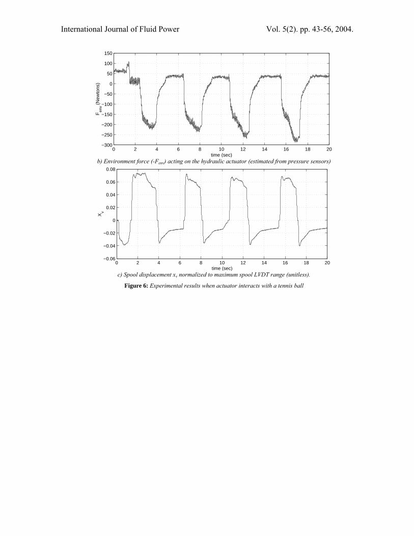
In the second set of experiments, the hydraulic actuator pushes a tennis ball against a steel block. In this case, we set ρ = 900, α = 0.15 to emphasize the force reflection property of the control scheme. In this scenario, the human

International Journal of Fluid Power Vol. 5(2). pp. 43-56, 2004.
operator first manipulates the actuator towards the tennis ball, and contact is made at about 2 sec. The operator then repeatedly pushes on the ball and releases the joystick. Observe, from Fig. 6-7, that throughout the experiment, the coordination error is also within 1.1 mm. Note that as the contact force (Fenv) increases, the spool displacement is decreased due to the pressure feedback in the valve passification control. Notice particularly that after the human has released the joystick, as the tennis bounces back and pushes the actuator backward, the joystick also springs back.
Estimate of )( Lx APFdtd
B−⋅
ε is used in the
passification control Eq. 17 of the valve. A bound on the estimation error is used in the robustness term. Figure 6-7 show the signal
Fx - APL and the error in predicting
)( Lx APFdtd
− . Since ε/B = 0.049s,
the robustness term in Eq. 17 is only 5-8 % of the signal Fx - APL.
7 Conclusions
A passive bilateral teleoperation control scheme has been proposed for an electrohydraulic actuator and a motorized joystick. The developed passive control ensures that the teleoperated machine behaves like a passive mechanical tool. Under sufficiently low manipulation bandwidth, coordination of the master joystick and the slave actuator is achieved. The efficacy of the control scheme has been experimentally validated. Compared to other control schemes such as impedance control, by ensuring passivity, the coupling stability of the hydraulic teleoperator with a broad class of passive objects can be guaranteed. Moreover, the control scheme does not require
knowledge of the impedances of the environment with which it is in contact.
Two areas of performance improvements are desirable. Firstly, the coordination performance can be improved if the deadband of the valve can be taken into account, without violating passivity. Secondly, the current control law presents a tradeoff between bandwidth (and hence coordination performance) and haptics property (in terms of large damping effect). This conflict is an artifact of the combination of valve passification and control methodologies. If alternate passification strategies (Li and Ngwompo, 2002) are adopted or a control scheme that takes into account the valve dynamics is developed, this conflict may be overcome.
In this paper, the effect of fluid compressibility is neglected. In the presence of fluid compressibility, the outlet and return flows of the valve will not be exactly the same even when a double ended actuator is used, so that the concept of a single load flow QL is not strictly valid. However, to the extent that the single load flow assumption is valid, the passivity property of the system will still be valid if the pressure feedbacks are obtained close to the valve ports. On the other hand, coordination performance will be worse when compressibility effects are significant (high pressure, large fluid capacitance). In our more recent and current research, valve passification as well as passive teleoperation algorithms have been developed that enable us to allow for different valve outlet and return flows, valve dynamics and fluid compressibility. However, by demanding better coordination control, these control laws are more complex, and all require the use of a force sensor at the joystick to measure the applied human force. The relatively simple control proposed in the present paper on the other hand, does not require the use of force sensor on the joystick.

International Journal of Fluid Power Vol. 5(2). pp. 43-56, 2004.
0 2 4 6 8 10 12 14 16 18 20−0.03
−0.02
−0.01
0
0.01
0.02
0.03
0.04
0.05
time (sec)
disp
lace
men
t (m
eter
s)
α qx
p
0 2 4 6 8 10 12 14 16 18 20−0.06
−0.04
−0.02
0
0.02
0.04
0.06
0.08
0.1
time (sec)
Xv
Fig. 5: Unconstrained joystick manipulation experiment. Top: displacements of scaled joystick and
actuator displacements; Bottom: spool displacement normalized to maximum spool LVDT range (unitless)
0 2 4 6 8 10 12 14 16 18 20−0.04
−0.03
−0.02
−0.01
0
0.01
0.02
0.03
0.04
time (sec)
disp
lace
men
t (m
eter
s)
α qx
p
a) Displacements of hydraulic actuator (dotted) and α-scaled joystick displacement (solid)
International Journal of Fluid Power Vol. 5(2). pp. 43-56, 2004.
0 2 4 6 8 10 12 14 16 18 20−300
−250
−200
−150
−100
−50
0
50
100
150
time (sec)
Fen
v (N
ewto
ns)
b) Environment force (-Fenv) acting on the hydraulic actuator (estimated from pressure sensors)
0 2 4 6 8 10 12 14 16 18 20−0.06
−0.04
−0.02
0
0.02
0.04
0.06
0.08
time (sec)
Xv
c) Spool displacement xv normalized to maximum spool LVDT range (unitless).
Figure 6: Experimental results when actuator interacts with a tennis ball

International Journal of Fluid Power Vol. 5(2). pp. 43-56, 2004.
0 2 4 6 8 10 12 14 16 18 20−0.2
−0.1
0
0.1
0.2
0.3
time (sec)
F x − A
PL (N
ewto
ns)
a) Total valve command: Fx - APL
0 2 4 6 8 10 12 14 16 18 20−0.05
−0.04
−0.03
−0.02
−0.01
0
0.01
0.02
0.03
0.04
time (sec)
∆ F
act (
New
tons
)
b) Robust passivity term is given by the error in estimating
x L[ ]d F APB dtε
−
Figure 7: Control signals when the actuator is interacting with a tennis ball

International Journal of Fluid Power Vol. 5(2). pp. 43-56, 2004.
Nomenclature
Ap Actuator cross-sectional area A Area for pressure feedback c A scalar B Damping coefficient Bw Passified valve bandwidth Cd Discharge coefficient E Coordination error Fx, Fact Spool stroking forces Fq Control input force Ff Fictitious flywheel actuation force Fenv Environment force f& Fictitious flywheel speed
f0 Fictitious flywheel speed thresholdMf Fictitious flywheel inertia Ps Supply pressure PL Difference in pressure between the
two actuator chambers q Joystick position QL(xv, PL), QL
Flow rate out of / into the valve
QLd Desired flow rate
Kq Flow rate gain ),( Lvq PxK Nonlinear load adjusted flow gain
Ksp Equivalent spring stiffness of passified valve
Kt(xv, PL) Nonlinear equivalent shunt conductance
M Joystick inertia s(⋅,⋅) Various supply rates Tq Human input force u Spool control force w Valve area gradient W Various storage functions xv Spool displacement xv
d Desired spool position xp Actuator piston position α Kinematic scaling ε Spool inertia γ Positive scalar ρ Power scaling ρh Hydraulic fluid density λ(t) Coordination error convergence
rate
Acknowledgements
This research is supported by the National Science Foundation under grant CMS-0088964.
References
Anderson, R. J. and Spong, M. W. 1989. Bilateral control of tele-operators with time delay. IEEE Transactions on Automatic Control, Vol. 34, No. 5, pp. 494-501.
Bradley, D. and Seward, D. W. 1998. The development, control and operation of an autonomous robotic excavator. Journal of Intelligent and Robotic Systems, Vol. 21, pp. 73–97.
Cannon, H. and Singh, S. 2000. Models for automated earthmoving. Experimental Robotics VI, Vol. 250, pp. 163–172.
Chen, P., Sun, Z., Mehlschau, J. J., Smith, N. and Frank, A. 1996. Development of a remote control system for a front-end loader. Applied Engineering in Agriculture, Vol. 12(6), pp. 623–631.
Colgate, J. E., Wannasuphoprasit, W., and Peshkin, M. A. 1996. Cobots: Robots for collaboration with human operators. Proceedings of the ASME Dynamic Systems and Control Division, Vol. 58, pp. 433–439.
Hannaford, B. and Ryu, J. 2002. Time domain passivity control of haptic interfaces. IEEE Transactions on Robotics and Automation, Vol. 18, No. 1, pp. 1-10.
Hogan, N. 1989. Controlling impedance at the man/machine interface. Proceedings of the 1989 IEEE International Conference on Robotics and Automation, pp. 1626-1631.
Krishnaswamy, K. and Li, P. Y. 2002. Passification of a two-stage pressure control valve. Proceedings of the 2002 American Control Conference, Vol. 6, pp. 4831-4836.
Lee, D. J. and Li, P. Y. 2003. Passive feedforward approach for linear dynamically similar bilateral teleoperatoed manipulators. IEEE Transactions on Robotics and Automation, Vol. 19, No. 3, pp. 443-456.
Lee, D. J. and Li, P. Y. 2002. Passive coordination control for nonlinear bilateral teleoperated manipulator. Proceedings of the 2002 IEEE International Conference on Robotics and Automation, pp. 3278-3283.

International Journal of Fluid Power Vol. 5(2). pp. 43-56, 2004.
Li, J. and Li, P. Y. 2000. Passive velocity field control approach to robot force control and contour following. Proceedings of the 2000 Japan-USA Symposium on Flexible Automation.
Li, P. Y. and Horowitz, R. 1997. Control of smart exercise machines, part 1: problem formulation and non-adaptive control. IEEE/ASME Transactions on Mechatronics, Vol. 2, pp. 237–247.
Li, P. Y. and Horowitz, R. 1999. Passive velocity field control of mechanical manipulators. IEEE Transactions on Robotics and Automation, Vol. 15, pp. 751–763.
Li, P. Y. and Horowitz, R. 2001. Passive velocity field control. Part 2: Application to robot contour following problems. IEEE Transactions on Automatic Control, Vol. 46, No. 9, pp. 1360-1371.
Li, P. Y. 2000. Towards safe and human friendly hydraulics: the passive valve. ASME Journal of Dynamic Systems, Measurement and Control, Vol. 122, pp. 402–409.
Li, P. Y. and Ngwompo, R. F. 2002. Passification of an electrohydraulic valves using bond graphs. Proceedings of the 2002 IFAC World Congress, Barcelona. (An extended version has been submitted to ASMA Journal of Dynamic Systems, Measurement and Control)
Luengo, O. and Barrientos, A. 1998. Telemanipulation and supervisory control of a backhoe excavator. SPIE Conference on Telemanipulator and Telepresence Technologies V, Vol. 3524, pp. 24–31.
Merritt, H. E. 1967. Hydraulic Control Systems. John Wiley & Sons, New York.
Ostaja-Starzewski, M. and Skibiniewski, M. 1989. A master slave manipulator for excavation and construction tasks. Robotics and Autonomous Systems, Vol. 4, pp. 333–337.
Parker, N. R., Salcudean, S. E., and Lawrence, P. D. 1993. Application of force feedback to heavy duty hydraulic machines. International Conference on Robotics and Automation, Vol. 1, pp. 375–381.
Salcudean, S. E., Hashtrudi-Zaad, K., Tafazoli, S., DiMaio, S. P. and Reboulet, C. 1999. Bilateral matched-impedance
teleoperation with application to excavator control. IEEE Control Systems Magazine, Vol. 19, No. 6, pp. 29–37.
Salcudean, S. E., Tafazoli, S., Hashtrudi-Zaad, K. and Lawrence, P. D. 1998. Evaluation of impedance and teleoperation control of a hydraulic mini-excavator. Proceedings of the Fifth International Symposium on Experimental Robotics, pp. 229–240.
Salcudean, S. E., Tafazoli, S., Lawrence, P. D., and Chau, I. 1997. Impedance control of a teleoperated mini excavator. International Conference on Advanced Robotics, pp. 19–25.
Stentz, A., Bares, J., Singh, S. and Rowe, P., 1999. A robotic excavator for autonomous truck loading. Autonomous Robots, Vol. 7, pp. 175–186.
Tafazoli, S., Peussa, P., Lawrence, P. D., Salcudean, S. E. and deSilva, C. W. 1996. Differential PWM operated solenoid valves in the pilot stage of mini excavators: modeling and identification. Proceedings of the ASME: Fluid Power Systems and Technology Division, Vol. 3, pp. 93–99.
Tafazoli, S., Lawrence, P. D. and Salcudean, S. E. 1999. Identification of inertial and friction parameters for excavator arms. IEEE Transactions on Robotics and Automation, Vol. 15, pp. 966–971.
Vidyasagar, M. 1993. Analysis of nonlinear dynamic systems. Prentice Hall, Englewood Cliffs, NJ, USA.
Willems, J.C. 1972. Dissipative dynamical systems, part 1: General theory. Archive for Rational Mechanics and Analysis, pp. 321–351.