Embed Size (px)
Citation preview
Report ITU-R M.2334-0 (11/2014)
Passive and active antenna systems for base stations of IMT systems
M Series
Mobile, radiodetermination, amateur
and related satellite services

ii Rep. ITU-R M.2334-0
Foreword
The role of the Radiocommunication Sector is to ensure the rational, equitable, efficient and economical use of the radio-
frequency spectrum by all radiocommunication services, including satellite services, and carry out studies without limit
of frequency range on the basis of which Recommendations are adopted.
The regulatory and policy functions of the Radiocommunication Sector are performed by World and Regional
Radiocommunication Conferences and Radiocommunication Assemblies supported by Study Groups.
Policy on Intellectual Property Right (IPR)
ITU-R policy on IPR is described in the Common Patent Policy for ITU-T/ITU-R/ISO/IEC referenced in Annex 1 of
Resolution ITU-R 1. Forms to be used for the submission of patent statements and licensing declarations by patent holders
are available from http://www.itu.int/ITU-R/go/patents/en where the Guidelines for Implementation of the Common
Patent Policy for ITU-T/ITU-R/ISO/IEC and the ITU-R patent information database can also be found.
Series of ITU-R Reports
(Also available online at http://www.itu.int/publ/R-REP/en)
Series Title
BO Satellite delivery
BR Recording for production, archival and play-out; film for television
BS Broadcasting service (sound)
BT Broadcasting service (television)
F Fixed service
M Mobile, radiodetermination, amateur and related satellite services
P Radiowave propagation
RA Radio astronomy
RS Remote sensing systems
S Fixed-satellite service
SA Space applications and meteorology
SF Frequency sharing and coordination between fixed-satellite and fixed service systems
SM Spectrum management
Note: This ITU-R Report was approved in English by the Study Group under the procedure detailed in
Resolution ITU-R 1.
Electronic Publication
Geneva, 2015
ITU 2015
All rights reserved. No part of this publication may be reproduced, by any means whatsoever, without written permission of ITU.

Rep. ITU-R M.2334-0 1
REPORT ITU-R M.2334-0
Passive and active antenna systems for base stations of IMT systems
(2014)
TABLE OF CONTENTS
Page
1 Scope .............................................................................................................................. 2
2 Related documents .......................................................................................................... 2
3 Introduction .................................................................................................................... 2
4 Technical and operational aspects of passive antenna systems for base stations of IMT
systems............................................................................................................................ 2
4.1 Definitions of passive antenna systems and associated components and
terminology ......................................................................................................... 2
4.2 Definitions for common performance parameters and tolerances ...................... 3
4.3 Guidelines on performance parameters and tolerances ...................................... 5
4.4 Consideration of advanced concepts (e.g. remote control of pattern and tilt) .... 5
5 Technical and operational aspects of active antenna systems for base stations of IMT
systems............................................................................................................................ 6
5.1 Definitions of active antenna systems and associated components and
terminology ......................................................................................................... 6
5.2 Definitions for common performance parameters and tolerances ...................... 7
5.3 Consideration of advanced concepts (e.g. remote control of pattern and tilt,
3D-beamforming and massive MIMO) .............................................................. 7
5.3.1 Tilt and radiation pattern control.......................................................... 9
5.3.2 Multiple input multiple output (MIMO) .............................................. 10
5.3.3 Differentiated antenna behaviours at different carrier frequencies ...... 11
5.3.4 Per resource block (or user equipment) transmission and reception.... 11
5.3.5 Applications in IMT Systems .............................................................. 11
6 Conclusions .................................................................................................................... 12
7 Terminology, abbreviations ............................................................................................ 12
8 References ...................................................................................................................... 13

2 Rep. ITU-R M.2334-0
1 Scope
This Report addresses several aspects of active and passive antenna systems for base stations of IMT
systems, including the definitions of antenna systems, associated components and terminology;
definitions for common performance parameters and tolerances; guidelines on performance
parameters and tolerances; and considerations of advanced concepts.
2 Related documents
– Recommendation ITU-R M.1457 – Detailed specifications of the terrestrial radio interfaces
of International Mobile Telecommunications-2000 (IMT-2000).
– Recommendation ITU-R M.2012 – Detailed specifications of the terrestrial radio interfaces
of International Mobile Telecommunications Advanced (IMT-Advanced).
– Report ITU-R M.2040 – Adaptive antennas concepts and key technical aspects.
3 Introduction
Mobile communication systems are developing towards more environmental friendliness and lower
operating and construction costs. Wireless access systems employing multi input multi output
(MIMO) and beamforming put forward higher requirements relating to beamforming systems and
integration of antennas and radio. In addition, forwards compatibility towards new antenna systems
will improve the competitiveness of IMT systems, which can protect the long-term investment of
telecommunication operators. Consequently, development of base station antenna design will be
important to solve these issues.
4 Technical and operational aspects of passive antenna systems for base stations of IMT
systems
4.1 Definitions of passive antenna systems and associated components and terminology
Each column of a traditional base station antenna array is driven by only one active transceiver. The
passive smart antenna of a traditional base station has beamforming capabilities, but it is limited due
to being implemented in analogue phase shifters whose effects apply to the whole bandwidth of the
antenna.
The typical RF structure of traditional passive antenna systems is given in Fig. 1.

Rep. ITU-R M.2334-0 3
FIGURE 1
An example RF structure of traditional passive BS antenna systems
4.2 Definitions for common performance parameters and tolerances
The list below provides definitions of the most important parameters for traditional antennas.
– Frequency range
The operating bandwidth of the antenna is defined by a continuous range of frequencies, specified in
MHz.
– Polarization
This parameter specifies the polarization or polarizations of the electric field radiated by the antenna;
the antenna can be linear polarized typically defined as Horizontal and Vertical polarization, slant
polarization typically defined as +45°/−45°, circular polarization typically defined as right-handed or
left-handed.
– Gain
The antenna gain is a measure of input power concentration in the main beam direction as a ratio
relative to an isotropic antenna source. It is determined as the ratio of the maximum power density in
the main beam peak direction, at a defined input power, compared to the power density of a loss-less
isotropic radiator with the same input power. It is defined in the far field of the antenna.
– Azimuth beamwidth
The 3 dB, or half power, azimuth beamwidth of the antenna is defined as the angular width of the
azimuth radiation pattern, including beam peak maximum, between points 3 dB down from maximum
beam level (beam peak).
4 Rep. ITU-R M.2334-0
– Elevation beamwidth
The 3 dB, or half power, elevation beamwidth of the antenna is defined as the angular width of the
elevation radiation pattern, including beam peak maximum, between points 3 dB down from
maximum beam level (beam peak).
– Electrical downtilt angle
For a fixed electrical tilt antenna, this parameter specifies the main beam pointing angles of the
elevation pattern; for a variable electrical tilt antenna, it defines the range of specified main beam
pointing angles of the elevation pattern.
– Elevation downtilt deviation
This parameter defines the maximum absolute deviation from the nominal tilt value in the elevation
beam pointing angle, which is supposed to be a measure of the accuracy of electrical tilt settings.
– Impedance
The characteristic impedance is the ratio between voltage and current flowing into an infinite length
guide, specified in Ohms.
– VSWR
The Voltage Standing Wave Ratio (VSWR) is defined as the ratio of the maximum amplitude to the
minimum magnitude of the voltage standing wave at an input port of an antenna. The VSWR is a
measure of the matching of the antenna to the source and feeder cables. A low VSWR will mean that
the reflections from the antenna are minimized.
– Return loss
This parameter is a measure of the difference between forward and reflected power measured at the
antenna port over the stated operating band. Return loss and VSWR both characterize the mismatch
between the transmission line and the antenna and are mathematically related.
– Cross polarization isolation
This parameter specifies the ratio of the power coupling between the two orthogonally polarized ports
of a dual polarization antenna.
– Passive intermodulation
Passive intermodulation is a low level signal created as the result of multiple high power transmit
signals in an antenna generated by ferromagnetic materials or by metal-to-metal discontinuities. This
relatively low power signal is generated at a frequency that is a mathematical combination of the
frequencies of the high power signals. It may degrade the uplink reception if it falls in the receive
bands.
– Front-to-back (F/B) Ratio, total power, 30°
The front-to-back ratio is a performance requirement stating the relationship between the beam peak
and the highest antenna gain in the rear 30 angular region of the azimuth cut, using the backward
(180º) direction as the reference. It can be supposed to be a measure of the interference radiated
backwards by the antenna. Here, the total power is the sum of the co-polarized and cross-polarized
radiation from an antenna port.
– First upper side lobe suppression
This parameter specifies the minimum suppression level of the side lobe above the horizon that is
closest to the main beam.

Rep. ITU-R M.2334-0 5
– Upper side lobe suppression, peak to 20°
This parameter specifies the minimum suppression level of the side lobes above the main beam peak
to a 20° angle referenced to the main beam peak.
– Cross-polar discrimination over sector
The cross-polar discrimination is defined as a ratio of the copolar component of the specified
polarization compared to the orthogonal cross-polar component over the sector. Cross-polar
discrimination is important for a low level of correlation between the orthogonally polarized
propagation channels. Correlation generated by the antenna can negatively affect receive diversity
and MIMO downlink performance of the system.
– Maximum effective power per port
This parameter specifies the maximum power which can be transmitted into one antenna port without
performance degradation.
– Interband isolation
This parameter defines the worst case coupling between any and all pair of ports in a multiple-band,
or broad-band antenna, specified as a minimum value in dB measured between any and all pair of
ports. Coupling between both co-polarized and cross-polarized pairs of ports is included. Coupling
between antenna ports can influence the level of filtering required for a given site configuration.
4.3 Guidelines on performance parameters and tolerances
Energy efficiency (EE) has been recognized as another important issue. Along with the transmit
power, circuit and system power are also important. Compared with traditional passive antennas,
some active antenna systems can provide an advantage in power saving.
Traditional antennas and feeder systems may give rise to considerable RF transmission loss. A
traditional mobile communication base station using a passive antenna, an antenna and feeder
subsystem consists of an indoor jumper (1/2"), a main coaxial cable (7/8"), a top tower jumper (1/2")
and an antenna. In this subsystem, a part of the BTS RF output power will be lost in the cable. As an
example, consider a set-up with antenna height of 20 m, indoor jumper length of 4 m, a top tower
jumper length of 2 m and a main coaxial cable length of 30 m. Table 1 shows the calculation of RF
power path loss in the feeder system.
TABLE 1
Calculation of RF power path loss in the feeder system
Frequency
(MHz)
Loss in main feeding
cable (30 m)
Loss in
jumper
(6 m)
Loss in
connector (4)
Total loss (dB) Power loss
(%)
900 0.038×30 0.1056×6 0.1×4 2.17 39%
1 800 0.056×30 0.1555×6 0.1×4 3.01 50%
From the calculation results, it is evident that the RF loss in a feeder system is considerable. And for
an active antenna system, the radio power loss in a feeder system may be smaller
4.4 Consideration of advanced concepts (e.g. remote control of pattern and tilt)
The remote control of the pattern is divided into two aspects: horizontal and vertical, the idea of the
remote control is proposed for adaptive coverage.

6 Rep. ITU-R M.2334-0
5 Technical and operational aspects of active antenna systems for base stations of IMT
systems
5.1 Definitions of active antenna systems and associated components and terminology
An active antenna implementation in a base station may incorporate many different forms of smart
antenna implementation, such as beam forming and/or MIMO with spatial multiplexing. An active
antenna implementation is differentiated from transmit diversity systems in that the propagation
patterns from its antenna elements are at least partially correlated such that spatial beam forming
patterns may be generated. To characterize an active base station antenna that is inclusive of all
possible implementations, adoption of reference architecture is needed to serve as a common baseline.
The radio architecture is represented by three main functional blocks, the transceiver unit array
(TXRUA), the radio distribution network (RDN), and the antenna array (AA). The transceiver units
(TXRU) interface with the base band processing within the base station, which depending on
implementation may also influence the radiated beam pattern.
The TXRUA consists of multiple transmitter units (TXU) and receiver units (RXU). The transmitter
units take the baseband input from the base station and provides the RF TX outputs. The RF TX
outputs may be distributed to the AA via a RDN. The RXU take the RF inputs from the antenna
elements to which they are mapped and provide input to the baseband processing. The number of
transmitters and the number of receivers may be unequal.
The RDN, if present, performs the distribution of the TX outputs into the corresponding antenna paths
and antenna elements, and a distribution of RX inputs from antenna paths in the reverse direction.
Note that the groups antenna elements involved in the TX and RX directions may be the same for
each direction, may be partially the same or may differ.
Figure 2 describes a general radio architecture that is generic to all types of active antenna system
structures.
FIGURE 2
General radio architecture
An active base station antenna may integrate the RF power amplifier, the low-noise amplifier (LNA),
the power supply system, the detection and control system, and may also incorporate the baseband
processor system. Techniques used for micro-cellular base station may be used, such as radio-over-
fibre (ROF) and optical fibre transmission, allowing the signal to be transmitted a longer distance
with smaller loss.
An example of an active antenna system (AAS) is given in Annex 1.
Radio
distribution
unit
(RDU)
Active antenna system (AAS), TXRU
TXRU #1
M x N
Array elements
AAS–
Array elements
#1
TXU/RXU #2 #2
TXU/RXU #K #K
#1 #2
#L
AAS–
RDU
(AAS-RDU)

Rep. ITU-R M.2334-0 7
5.2 Definitions for common performance parameters and tolerances
Besides traditional passive antenna parameters, the following non-exhaustive list of performance
parameters is relevant for AAS:
1) Adjustment range of the maximum output power of the array, i.e. antenna radiated power
adjustment range;
2) Maximum allowable input level, i.e. maximum input signal level that can maintain the
antenna performance and will not damage antenna;
3) Input dynamic range;
4) Spurious emission of integrated transmitter;
5) Adjacent channel interference of integrated transmitter;
6) Ripple in band of integrated PA;
7) Receiver sensitivity;
8) Antenna pattern for receiving;
9) Antenna pattern for transmitting;
10) Directivity;
11) The total power of the antenna, i.e. The total electrical power consumption by antenna;
12) Equivalent isotropic radiated power (e.i.r.p.);
13) Effective isotropic reference sensitivity (e.i.r.s.);
14) Polarization related parameters, e.g. XPR (cross-polarization ratio) and so on.
In addition, intra-band isolation might also need to be considered along with inter-band isolation.
5.3 Consideration of advanced concepts (e.g. remote control of pattern and tilt,
3D-beamforming and massive MIMO)
In active antenna, radiation element is integrated with RF module; this structure can improve the
power efficiency of base station RF power amplifier (PA). The future key technology is for
miniaturization of remote device and integration of multi-system.
3D-beamforming, user specific beam forming and massive MIMO attracts significant interest
recently because it can enhance system performance through the use of antenna systems having a
two-dimensional array structure providing adaptive weighting factor control over elevation
dimension and azimuth dimension. Since by now there is only mature 2D channel model, e.g. ITU-R
M.2135, a new channel model which can model both vertical and horizontal dimension is needed to
evaluate the gain of 3D-beamforming and massive MIMO.
For the traditional base station antenna with only horizontal beamforming ability, the maximum gain
point in vertical plane only have one main lobe that can be tilted. As displayed in Fig. 3. The SNR of
the users away from the maximum gain point on main lobe will deteriorate. The terminals departing
from the main lobe coverage direction will have SNR decreasing significantly. Such situation also
exists for users in vertical plane. For the move towards the base station, the gain of fixed antenna will
be reduced obviously, as well as the SNR, which affects the throughput improvement.

8 Rep. ITU-R M.2334-0
FIGURE 3
The improvement limitations on SNR of horizontal beamforming
Height
SNR
Height
Height
Height
SNR
For active antenna, we can dynamically adjust the beam to cover the users in the system within the
maximum gain of the antennas, so that the SNR, as well as the throughput, will be improved. This
gain is more efficient and obvious to the mobile terminals on the vertical direction, just as shown in
Fig. 4. Such adjusting ability of vertical beam also provides efficient solutions to such hot point as
tall buildings. Dynamical beam adjusting is also useful to mobile terminal in horizontal plane. It is
worth pointing out that the adjusting capability of beam must cover the main users in a cell in order
to achieve a specific gain. This needs to be considered with specific parameters of network
optimization, which includes the base station installation height, mechanical downtilt adjusting. The
higher demand of the beam adjusting in wide angle range needs more transceivers to drive each
column of antenna array, which further brings the problem of system cost-benefit optimization.
FIGURE 4
Examples of SNR improvement by horizontal and vertical beamforming
Height
SNR
Height
Height
Height
SNR
Array antenna might also beamform out-of-band (OoB) signals differently to in band signals, while
the radiation pattern of OoB signals brings the pattern of ACLR. This is an obvious difference
between the active base station and traditional passive base station antenna. In the traditional base
station, each transmitter connects to an independent antenna. Generally speaking, the output signals

Rep. ITU-R M.2334-0 9
lie in three categories: useful signal for communication, OoB nonlinear signal generated by the
nonlinearity of transmitter, and thermal noise. All of the three kinds of signals transmit by the same
antenna, so the spatial radiation patterns for them are all the same. As is known to all, ACLR is
defined as the power ratio of the in-band useful signal and OoB signal that leaks to adjacent bands.
For the traditional base station, the patterns for these two signals are the same, so the ACLR is the
same for all spatial directions. In a three-dimensional space, the pattern of ACLR of traditional base
station is spherical. Compared with the traditional base station, each dipole may connect to different
transmitter. For signals useful to beamforming, signals from various transmitters exhibit strong
correlation. However, the OoB signals show low correlation, as the nonlinearity of each transmitting
channel does not converge. For example, the third-order intermodulation from different amplifiers,
even from the same generation, does not show complete correlation. The thermal noise from different
transmitters is independent. Uncorrelated signals will show different spatial pattern. As shown in
Fig. 5, the power ratio, or ACLR, exhibits spatial direction because of the different directional
characteristic of useful signals and OoB signals. This feature should call for attention for system
coexistence and disturbing analysis.
FIGURE 5
An example of the formation of ACLR direction for active base station with a particular beam pattern (left: useful signal;
middle: OoB signal with correlation of 0.3; right: ACLR)
5.3.1 Tilt and radiation pattern control
Antennas are usually manufactured with a fixed beam width, and antenna manufacturers typically
offer a limited number of beam width variations within their conventional product lines. Conventional
BS installations often introduce physical tilt to the antenna in order to orient the main lobe of the
antenna response towards the ground. Antenna tilt is selected to optimize desired cell coverage and
to minimize interference to and from adjacent cells. Remote Electrical Tilt (RET) devices can be
installed to allow mechanical adjustment of the phase shift so that the antenna tilt angle is remotely
controlled.
An AAS may dynamically control the elevation and azimuth angles, as well as the beam width of its
radiation pattern via electronic means. Electronic control may be used along with mechanical means.
The AAS radiation pattern may be adapted to the specific deployment scenario and possibly to
changing traffic patterns. The AAS radiation pattern may also be independently optimized for
different links such as independently for uplink and downlink, for coverage and beam forming gain
purposes.
5.3.1.1 Cell partitioning in the horizontal and vertical plane
The concepts of tilt and beam width control can be extended by a technique known as cell partitioning
in which the cell is subdivided in vertical or horizontal directions by adjustment of the antenna pattern.
For example one cell partition is located close to the BS and the other cell partition is located farther
away from the BS.

10 Rep. ITU-R M.2334-0
As stated above, active antenna have the ability of vertical and horizontal beamforming, and can
extend the spatial signal processing ability from horizontal plane to vertical plane. Fig. 6 shows
typical applications of active antennas.
FIGURE 6
Typical application for active antenna base station
a) Beam-forming for terminals, b) diversity receiving agilely, c) independent adjusting of uptilt and downtilt
d) Independent carrier tilt adjusting, e) independent modulation tile adjusting, f) vertical-horizontal cell splitting
Obviously shown as Fig. 6 f), active antenna technique can realize the vertical and horizontal cell
splitting. It can also adjust to the change of service environments by configuring beams. For example,
active antennas can dynamically adjust the beam coverage according to each cell load to maximize
the system throughput. It can also statically configure vertical and horizontal stationary beam to form
multiple cells, to theoretically improve the resource multiplexing ratio by fold increase.
Traditional passive base station antenna only supports horizontal beamforming, i.e. 2D-beamforming.
Active antenna can dynamically adjust the spatial signal beams vertically and horizontally, named
3D-beamforming. If the multi-stream transmission is extended to vertical plane, the active antenna
will extend MIMO from 2D to 3D. The inter-cell interference coordination (ICIC) will bring greater
system benefits for active antenna by dynamical adjusting for both vertical and horizontal dimensions
of beams between cells.
5.3.2 Multiple input multiple output (MIMO)
MIMO is a general term that includes the various spatial processing techniques: beam forming,
diversity, and spatial multiplexing. Brief description of each is provided below.
– Beam forming: The use of dedicated beam formed towards the UE when the data
demodulation based on dedicated reference signal is supported by the UE;
– Diversity: The use of diversity techniques to jointly optimize in the spatial and frequency
domain through the use of, for example, spatial-frequency block code (SFBC) or frequency
switching transmit diversity (FSTD), or combinations of them;
– Spatial multiplexing: The transmission of multiple signal streams to one (SU-MIMO)
or more (MU-MIMO) users using multiple spatial layers created by combinations of the
available antennas.
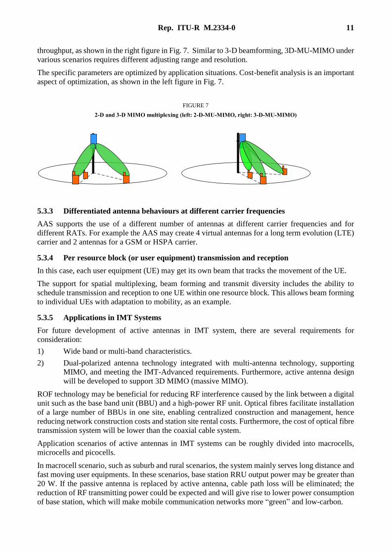
Multi user MIMO means that users multiplex the same time slot. For traditional antenna, the multiple
users can only exist in horizontal direction. If two users have identical horizontal angle, but different
vertical angle, the traditional base station cannot take advantage of resource multiplexing, which is
shown as the left figure in Fig. 7. For active antenna, different mobile terminals can be distinguished
both horizontally and vertically due to vertical and horizontal adjusting ability of the beams, so the
possibility of multi user MU matching increases significantly, which greatly improves the system
UE 1
UE 2
Rx 1 Rx 2 Tx Rx
f1
f2 LTE
GSM Cell2 Cell1
Rep. ITU-R M.2334-0 11
throughput, as shown in the right figure in Fig. 7. Similar to 3-D beamforming, 3D-MU-MIMO under
various scenarios requires different adjusting range and resolution.
The specific parameters are optimized by application situations. Cost-benefit analysis is an important
aspect of optimization, as shown in the left figure in Fig. 7.
FIGURE 7
2-D and 3-D MIMO multiplexing (left: 2-D-MU-MIMO, right: 3-D-MU-MIMO)
5.3.3 Differentiated antenna behaviours at different carrier frequencies
AAS supports the use of a different number of antennas at different carrier frequencies and for
different RATs. For example the AAS may create 4 virtual antennas for a long term evolution (LTE)
carrier and 2 antennas for a GSM or HSPA carrier.
5.3.4 Per resource block (or user equipment) transmission and reception
In this case, each user equipment (UE) may get its own beam that tracks the movement of the UE.
The support for spatial multiplexing, beam forming and transmit diversity includes the ability to
schedule transmission and reception to one UE within one resource block. This allows beam forming
to individual UEs with adaptation to mobility, as an example.
5.3.5 Applications in IMT Systems
For future development of active antennas in IMT system, there are several requirements for
consideration:
1) Wide band or multi-band characteristics.
2) Dual-polarized antenna technology integrated with multi-antenna technology, supporting
MIMO, and meeting the IMT-Advanced requirements. Furthermore, active antenna design
will be developed to support 3D MIMO (massive MIMO).
ROF technology may be beneficial for reducing RF interference caused by the link between a digital
unit such as the base band unit (BBU) and a high-power RF unit. Optical fibres facilitate installation
of a large number of BBUs in one site, enabling centralized construction and management, hence
reducing network construction costs and station site rental costs. Furthermore, the cost of optical fibre
transmission system will be lower than the coaxial cable system.
Application scenarios of active antennas in IMT systems can be roughly divided into macrocells,
microcells and picocells.
In macrocell scenario, such as suburb and rural scenarios, the system mainly serves long distance and
fast moving user equipments. In these scenarios, base station RRU output power may be greater than
20 W. If the passive antenna is replaced by active antenna, cable path loss will be eliminated; the
reduction of RF transmitting power could be expected and will give rise to lower power consumption
of base station, which will make mobile communication networks more “green” and low-carbon.
12 Rep. ITU-R M.2334-0
In future, active antennas will be applied widely in microcells, picocells. In the urban areas, user
equipments are intensive and vehicles are low-speed, high data rate transmission in short distance is
required, so the system is required to reduce the RF output power, and the key consideration is
improving service capacity in complex scenarios. Furthermore, multi-point coordination or
multi-antenna enhancement technology may be used to meet the IMT-advanced requirements for
spectrum efficiency in cell border.
Smaller active antennas, with only one radiation element and RF output power at 100 mW or less,
will be used in the indoor coverage systems assuming frequency band below 4 GHz. It is now
generally considered that much higher frequencies will be used in future IMT system, possibly up to
100 GHz. At these frequencies, more output RF power and more radiation elements will be required
to cover a similar range. Active antennas of micro-power may be small and light, so they can be
installed in the walls of buildings, poles or street lights conveniently, to eliminate the blind spots of
wireless coverage.
6 Conclusions
Several aspects of active and passive antenna systems for base stations of IMT systems have been
studied in this Report, including the definitions of antenna systems, associated components and
terminology. The development of base station antenna design along these lines is foreseen to solve a
number of important issues in IMT systems, such as environmental friendliness and lower operating
and construction costs.
7 Terminology, abbreviations
AA Antenna array
AAS Active antenna system
ACLR Adjacent channel leakage ratio
BBU Base band unit
BTS Base transceiver station
EE Energy efficiency
EIRP Equivalent isotropic radiated power
EIRS Effective isotropic reference sensitivity
FSTD Frequency switching transmit diversity
ICIC Inter-cell interference coordination
LNA Low-noise amplifier
LTE Long term evolution
MIMO Multi input multi output
MU-MIMO Multi user MIMO
OoB Out-of-band
PA Power amplifier
RAT Radio access technology
RDN Radio distribution network
RDU Radio distribution unit

Rep. ITU-R M.2334-0 13
RET Remote electrical tilt
ROF Radio-over-fibre
RRU Remote radio unit
RX Receiver
RXU Receiver unit
SFBC Spatial-frequency block code
SNR Signal-to-noise ratio
SU-MIMO Single user MIMO
TX Transceiver
TXRUA Transceiver unit array
TXRU Transceiver unit
TXU Transmitter units
UE User equipment
VSWR Voltage standing wave ratio
XPR Cross-polarization ratio
8 References
[1] Huawei Technologies Co., Ltd. Active Antenna System: Utilizing the Full Potential of Radio Sources
in the Spatial Domain, November 27, 2012.
[2] Recommendation on Base Station Antenna Standards, NGMN Alliance, version 9.6.
Annex 1
Example of an AAS
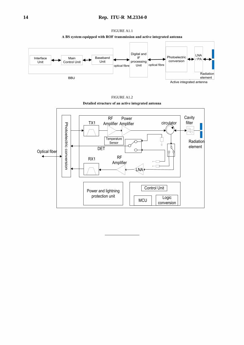
Figure A1.1 demonstrates a BS system engineering prototype with ROF transmission and an active
integrated antenna. Fibre is used for providing IQ samples to the radio. In general, alternative
technologies can be used for providing IQ, or even the whole base station can be integrated.
However the IQ is provided to the radio, the radio requirements should be similar.
A detailed structure of active integrated antenna is shown in Fig. A1.2. In the system, digital and
Intermediate Frequency (IF) processing units are inserted, so BBU and RRU can be separated. The
digital IF processing unit is used as proximal machine, active integrated antenna is used as a remote
machine. In this example, advanced technology has been able to realize 4-channel FDD active
integrated antenna and 4-channel TDD active integrated antenna.
It should be noted that this is just one example of AAS implementation.
14 Rep. ITU-R M.2334-0
FIGURE A1.1
A BS system equipped with ROF transmission and active integrated antenna
Interface
Unit
Main
Control Unit
Baseband
Unit
Digital and
IF
processing
Unit optical fibre
Photoelectric
conversion
LNA
/ PA
Radiation
element
Active integrated antenna
BBU
optical fibre
FIGURE A1.2
Detailed structure of an active integrated antenna
Ph
oto
ele
ctric
co
nve
rsio
n
Power and lightning
protection unit
LNA
TX1
RX1
DET
RF
Amplifier
Power
Amplifier
Temperature
Sensor
MCULogic
conversion
Control Unit
Optical fiber
RF
Amplifier
Radiation
element
Cavity
filtercirculator
______________