Embed Size (px)
Citation preview
ISSN 1068�798X, Russian Engineering Research, 2010, Vol. 30, No. 1, pp. 41–44. © Allerton Press, Inc., 2010.Original Russian Text © V.P. Cherkashin, 2010, published in Vestnik Mashinostroeniya, 2010, No. 1, pp. 49–52.
41
The life of traditional pass�through lathe tools,containing lateral and front cutting edges, is deter�mined by the life of the front cutting edges, whichshapes the surface of the machined shaft. As shown byoperational experience, observations, and measure�ments, the wear of the front cutting edge is three timesthat of the lateral cutter. The growth of the rear wearfacet at the front edge is about three times as fast.
In regrinding to eliminate the rear wear facet (withonly slight adjustment elsewhere), both the worn frontcutting edge and the unworn and functional lateralcutting edges will be reground. This makes no sense,especially when using expensive superhard materials.To resolve this problem, we may use lathe cutters withindependent cutting systems. Such heads were devel�oped for hobbing heads [1–4] and subsequentlyextended to tooth�cutting mills [5], slotting tools[6, 7], and hobbing cutters [8, 9] for industrial gearmanufacture [10].
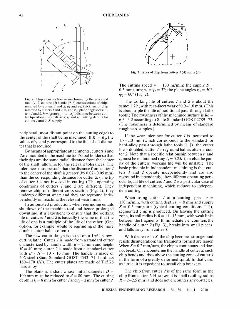
The pass�through lathe cutter with independentcutting systems (Fig. 1) includes cutters of two types.Cutter 1 operates only at the lateral cutting edges; thefront cutting edges are included solely to permit sim�ple and expedient positioning of the cutters relative toone another and the shaft being machined. Cutter 2only includes front cutting edges; it forms themachined surface of the blank. Cutter 2 operates inconstrained conditions and removes relatively smallquantities of chip. Cutter 1 operates in unconstrainedconditions and removes large volumes of chip. There�fore, the life of cutters 1 and 2 is approximately thesame and may be regulated by adjusting the cuttingdepth t2 of cutter 2—in other words, by changing angleϕ2 and height h (Fig. 2). As a result, the cutting deptht1 of cutter 1 is also modified. The pass�through lathetool with independent cutting systems takes the formof a composite cutter, since it consists of two specialtools, whose handles are screwed together.
Cutter 1 may be obtained from a standard lathecutter by cutting a recess of 0.5H at the bottom of thehandle (Fig. 1), so that K1 = K2. A design in which K1 =K2 = H is possible. Note that the decrease in handleheight for cutter 1 may be compensated by increasing
its width. (In other words, a standard cutter with abroader handle may be employed.) This increases theflexural strength of the handle and improves heattransfer from the cutting zone. Cutter 2 may also beproduced from a standard lathe tool, by cutting a lowernotch (depth C = 0.5–1.0 mm) whose length is suchthat the handle does not touch the hard�alloy plate ofcutter 1. Note that the notch may be compensated byincreasing the handle width for cutter 2, with improve�ment in heat transfer from the cutting zone.
The front angles γ1 of cutter 1 and γ2 of cutter 2 aremeasured from the line connecting the cutter tip (the
Pass�Through Lathe Cutter with Independent Cutting SystemsV. P. CherkashinOAO Giprouglemash
Abstract—The design of a pass�through lathe cutter with independent cutting systems is considered. Thecutter is based on a composite design: one tool has lateral cutting edges; the other has a front cutting edge.The possibility of harmonizing the regrinding of the two tools is analyzed.
DOI: 10.3103/S1068798X10010107
1
2
3
D
d
B
A
H
C
M1M
2
γ 2
L K1
K2
γ1
Fig. 1. Pass�through lathe tool with independent cuttingsystems: (1, 2) cutters; (3) blank (shaft): D, d, diameter ofblank before cutting and shaft after cutting; H, height ofthe handle for cutter 2; C, depth of recess in the handle forcutter 2; μ1 and μ2, inclination of the lines connecting thetips of cutters 1 and 2 and the center of the shaft, respec�tively, to the horizontal; A, B, tips of cutters 1 and 2.
42
RUSSIAN ENGINEERING RESEARCH Vol. 30 No. 1 2010
CHERKASHIN
peripheral, most distant point on the cutting edge) tothe center of the shaft being machined. If K1 = K2, thevalues of γ1 and γ2 correspond to the final shaft diame�ter that is required.
By means of appropriate attachments, cutters 1 and2 are mounted in the machine tool’s tool holder so thattheir tips are the same radial distance from the centerof the shaft, allowing for the relevant tolerances. Thetolerances must be such that the distance from cutter 1to the center of the shaft is greater (by 0.02–0.05 mm)than the corresponding distance for cutter 2. (The tipof cutter 1 is not involved in cutting.) The operatingconditions of cutters 1 and 2 are different. Theyremove chip of different cross section (Fig. 2); theyundergo different wear; and they are reground inde�pendently on reaching the relevant wear limits.
In automated production, when regrinding entailsshutdown of the machine tool and hence prolongeddowntime, it is expedient to ensure that the workinglife of cutters 1 and 2 is basically the same or that thelife of one is a multiple of the life of the other. (Oneoption, for example, would be regrinding of the moredurable cutter half as often.)
The new cutter design is tested on a 1A64 screw�cutting lathe. Cutter 1 is made from a standard cuttercharacterized by handle width B = 25 mm and heightH = 40 mm; cutter 2 is made from a standard cutterwith B × H = 10 × 16 mm. The handle is made of40X steel (State Standard GOST 4543–71; hardness160–170 HB). The cutter plates are made of T15K6hard alloy.
The blank is a shaft whose initial diameter D =100 mm must be reduced to d = 80 mm. The cuttingdepth is t1 = 8 mm for cutter 1 and t2 = 2 mm for cutter 2.
The cutting speed v = 130 m/min; the supply S =0.5 mm/turn; γ1 = γ2 = 3°; the plane angles ϕ1 = 50°,ϕ2 = 60° (Fig. 2).
The working life of cutters 1 and 2 is about thesame: 1.7 h, with rear�facet wear of 0.9–1.0 mm. (Thisis about triple the life of traditional pass�through lathetools.) The roughness of the machined surface is Ra =6.3–3.2 according to State Standard GOST 2789–73.(The roughness is determined by means of standardroughness samples.)
If the wear tolerance for cutter 1 is increased to1.8–2.0 mm (which corresponds to the standard forhard�alloy pass�through lathe tools [11]), the cutterlife is doubled; cutter 1 is reground half as often as cut�ter 2. Note that a specific relationship between t1 andt2 must be maintained (say, t2 = 0.25t1), or else the par�ity of the cutters' working life will be unstable. Thebasic principle in independent machining is that cut�ters 1 and 2 operate independently and are alsoreground independently, after different operating peri�ods. Equal life of cutters 1 and 2 is a particular case ofindependent machining, which reduces to indepen�dent cutting.
When using cutter 1 at a cutting speed v =130 m/min, with cutting depth t1 = 8 mm and supplyS = 0.5 mm/turn (typical cutting conditions [11]),segmented chip is produced. On leaving the cuttingzone, its coil radius is R = 11–13 mm, with weak linksbetween the fragments. It immediately encounters thehandle of cutter 2 (Fig. 3), breaks into small pieces,and falls away from cutter 1.
With decrease in S, the chip becomes stronger andresists disintegration; the fragments formed are larger.When S = 0.2 mm/turn, the chip is continuous and doesnot break. On encountering the handle of cutter 2, suchchip bends and rises above the cutting zone of cutter 1in the form of a greatly deformed spiral. In that case,as a rule, it is expedient to install chip breakers.
The chip from cutter 2 is of the same form as thechip from cutter 1. However, it is small (coiling radiusR = 2–2.5 mm) and does not encounter any obstacles.
t2t1
S
h2
34
5
ϕ1
ϕ2
a 2
a 1
Fig. 2. Chip cross section in machining by the proposedtool: (1, 2) cutters; (3) blank; (4, 5) cross sections of chipsremoved by cutters 1 and 2; a1 and a2, thickness of chipremoved by cutters 1 and 2; ϕ1 and ϕ2, plane angles for cut�ters 1 and 2; h = t2(tanϕ1 – tanϕ2), distance between cut�ter tips along the shaft axis; t1 and t2, cutting depths forcutters 1 and 2; S, supply.
A
B
Fig. 3. Types of chip from cutters 1 (A) and 2 (B).
1
RUSSIAN ENGINEERING RESEARCH Vol. 30 No. 1 2010
PASS�THROUGH LATHE CUTTER WITH INDEPENDENT CUTTING SYSTEMS 43
SOME CHARACTERISTICS OF THE NEW TOOL
(1) The front angles γ1 and γ2 and the angles μ1 andμ2 are related to K1 and K2 and the shaft diameter dafter machining (Fig. 1). For example, if γ1 = γ2 = 3°when d = 80 mm and K1 = K2 = 8 mm, then
L = [(0.5d)2 – ]0.5 = 39.2 mm,
and
To machine a shaft with a final diameter d' = 85 mm,we must adjust γ1 and γ2, since the inclination of the linesconnecting the cutter tip and the center of the shaft ismodified. (The front surface of the cutters isunchanged.) In that case
L' = [(0.5d ')2 – ]0.5 = 41.73 mm.
Correspondingly, we find that
To restore γ1 and γ2 to 3° (if required, for example,because the working lives of cutters 1 and 2 are widelydivergent), regrinding of the cutters is required (with�out change in and
If the blank is characterized by numerous stageswith different diameters, γ1 and γ2 must be selected fora stage of mean diameter.
In machining shafts that contain a noncylindrical(spherical or conical) solid of revolution on a numeri�cally controlled lathe, the program will appropriatelycorrect the positions of cutters 1 and 2 in the indepen�dent cutting system. Correspondingly, γ1 and γ2 will beslightly changed.
(2) In the pass�through lathe cutter with indepen�dent cutting systems, cutter 1 performs most of thework, with the greatest heat liberation. We may assumethat cutter 2 machines a hot blank (shaft) for a certaintime.
The cutter life with a preheated blank was studiedin [12]; this research continues today [13]. The cutterlife is extended by a factor of 3–4 when machining ablank preheated to 600–700°C (for example, by aburner) [12, 13]. (Sometimes, this factor is as much as7–8 [12].)
However, with an independent cutting system, theblank reaching cutter 2 is not preheated, but rather hasonly been heated since the onset of cutting; corre�spondingly, its temperature is much lower.
K12
μ1 K1/L( )arctan 11.3°,= =
μ2 K2/L( )arctan 11.3°.= =
K12
μ1' K1/L '( )arctan 10.8°;= =
μ2' K2/L '( )arctan 10.8°;= =
Δμ 11.3° 10.8°– 0.5°;= =
γ1' 3° Δμ+ 3° 0.5°+ 3.5°;= = =
γ2' 3° Δμ– 3° 0.5°– 2.5°.= = =
μ1' μ2' ).
The surface of the shaft arriving at cutter 2 is nomore than 250–300°C, according to [14]. (By con�trast, the temperature in the cutting zone reaches1000–1100°C.) Analogous temperatures at the shaftsurface are observed by means of thermal dyes whenusing standard cutters and cutters with independentmachining systems. However, it is nevertheless possi�ble to extend the life of cutter 2, as the following testresults indicate.
A shaft is ground from a diameter of 84 mm to80 mm by means of the proposed tool; this corre�sponds to a cutting depth of 2 mm. The other data arethe same as in the previous example (grinding a shaftfrom a diameter of 100 mm to 80 mm). In this case,cutter 1 is not involved in machining, since the 2�mmlayer is removed by initial cutter 2.Thus, for cutter 2,the incoming blank is unheated, and cutter life isreduced by a factor of 1.05–2; in other words, the life ofcutter 2 is 1.05–2 times longer when the blank isheated as a result of machining by cutter 1. For longershafts, the increase in cutter life is greater.
Thus, the relative life of cutters 1 and 2 depends onmany factors.
Note that the adjustment of γ1 and γ2 when machin�ing shafts with many stages characterized by differentdiameter may affect cutter life in different ways. Forexample, with increase in γ1 and γ2, cutter life mayincrease (since the cutting force is reduced) or decrease(since the sharpness at the tip is increased and heatextraction from the cutting zone is impaired) [15].
Note also that cutter 2 may last longer than cutter 1in certain conditions—for example, with increase inhandle width for cutter 2, decrease in its cutting depth,or the machining of long shafts.
Maintaining a stable relationship between theworking lives of cutters 1 and 2 (equal values or a fixedratio) entails taking account of the specific productionconditions.
CONCLUSIONS
(1) The pass�through lathe cutter with independentcutting systems may expediently be used in mass pro�duction on numerically controlled lathes or on univer�sal screw�cutting lathes, since its working life is abouttriple that of the traditional pass�through cutter.
(2) Extending the working life of cutters (beforeregrinding is required) is important in automated pro�duction systems.
(3) Introducing the new tool entails practically noproduction costs.
REFERENCES
1. Russian Patent 1775247.2. Gormanyuk, N.A. and Cherkashin, V.P., Hobbing
Head with Independent Cutting System for the ActiveSection and Base of Conical�Gear Teeth, Nauchno�tekhnicheskie dostizheniya i peredovoi opyt v ugol’noi
44
RUSSIAN ENGINEERING RESEARCH Vol. 30 No. 1 2010
CHERKASHIN
promyshlennosti (Progress and Cutting�Edge Experiencein the Coal Industry), Moscow: TsNIEIugol, 1990,no. 8, pp. 26–27.
3. Cherkashin, V.P., Parameter Selection for a HobbingHead with Independent Cutting Systems, StankiInstrum., 2006, no. 12, pp. 14–16.
4. Cherkashin, V.P., Analysis of the Life of Hobbing Toolswith Independent Cutting Systems, Vestn. Mashinostr.,2006, no. 6, pp. 53–58.
5. Cherkashin, V.P., Hobbing Tool for the Manufacture ofHeavy�Duty Gear Transmissions in Coal Combines,Gorn. Mash. Avtomat., 2002, no. 3, pp. 8–11.
6. Cherkashin, V.P. and Starovoitov, V.G., Hobbing Toolfor Domestic Production of Spare Parts for ImportedCoal�Mining Equipment, Gorn. Mash. Avtomat., 2003,no. 2, pp. 34–37.
7. Cherkashin, V.P. and Sokolov, I.I., Planetary Transmis�sions in Coal Combines, Gorn. Mash. Avtomat., 2004,no. 9, pp. 33–35.
8. Cherkashin, V.P., Sokolov, I.I., and Ishchenko, V.A.,Gear Production for Coal�Face Combines, Tekhn.Mashinostr., 2001, no. 2, pp. 69–71.
9. Cherkashin, V.P., Design and Manufacture of GearClutches for Coal Combines, Gorn. Mash. Avtomat.,2002, no. 4, pp. 19–22.
10. Azerskaya, K.F., Antonov, A.D., Antonov, S.D., et al.,Ugledobyvayushchaya tekhnika instituta Giprouglemash iee sozdateli (Coal�Extraction Equipment and ItsDesigners at OAO Giprouglemash), Moscow: DesignBureau Alliance, 2005.
11. Baklunov, E.D., Beloukhov, A.K., Zhebin, M.I., et al.,Spravochnik metallista (Metallurgical Handbook),Moscow: Mashinostroenie, 1977, vol. 3.
12. Lopadze, T.N., Iznos rezhushchego instrumenta (Wear ofCutting Tools), Moscow: Mashgiz, 1958.
13. Kotel’nikov, V.I., Influence of Blank Heating on theLife of Lathe Tools, Stanki Instrum., 2008, no. 4,pp. 13–15.
14. Granovskii, G.I. and Granovskii, V.G., Rezanie metallov(Metal Cutting), Moscow: Vysshaya Shkola, 1985.
15. Kalashnikov, S.N., Zuboreznye reztsovye golovki (Hob�bing Heads), Moscow: Mashinostroenie, 1972.