Embed Size (px)
DESCRIPTION
technical documentation
Citation preview
Pasolink V4
Version 1.3 July 2006
Personnel Training
3
July 2006 gm/nec/general/pasolinkv4/trainees 3
Module 1Equipment Overview
ObjectivesAt the end of this module, you will be able to do the following:
•Describe in your own words the component parts of the Pasolink V4
References:Pasolink V4 User (Instruction) Manual ROI-S0xxxx-051E
Abbreviations ROI-S04491-052EGeneral System Description ROI-S04604-052EMeasurement Procedure ROI-S04607-054ETRP Equipment Description ROI-S04605-054ERadio Frequency Assignment (n GHz) ROI-various-05xEMDP Equipment Description ROI-S04488-058EInstallation and Initial Lineup ROI-S04606-054E
Pasolink V4 Sub-band Change Procedure
Pasolink V4 MTD (1+0 / 1+1) PL035-01
Pasolink V4
Version 1.3 July 2006
Personnel Training
4
Features Summary:•Only one coaxial cable•Various mounting methods for IDU, ODU and Antenna•Field tunable local oscillator (Synthesizer)•Changing RF frequency without measuring equipment or changing modules•Variable TX Power Control: 0 to 30 dB, 1 dB steps and 30dB fixed attenuator option.•Automatic Transmitter Power Control & Manual Transmitter Power Control available•1+0 unprotected or 1+1 Hot Standby / Space Diversity / Twin Pass System•7/8/13/15/18/23/26/38 GHz bands•IDU is the same for all bands•Fixed bit rate IDU options: 4 x 2Mb/s•Software settable transmission rate IDU option (Bit Rate Free) - 16x2 / 8x2 / 4x2 / 2x2 Mbit/s / 10 Base-T / 100 Base-TX)•LAN interfaces option (x2): separated, auto configuration or various fixed rate, IEE 802.3•Wayside (Option in 16x2 Mb/s only): 1x2 Mb/s G703 (if optional WS INTFC card is fitted) or LAN (if optional SC LAN INTFC card is fitted), RJ45 connector•Tributary impedance: 75 ohms / 120 ohms, D-type connector•ODU same physical size for 7-38GHz bands•Antenna close coupled to Outdoor Unit (option for 13-38GHz ODUs only) •Supports Direct Mount to antennas with diameters of 0.2m up to 1.8m (13-38GHz)•Antenna remote from Outdoor Unit (option)
•N-type/SMA coaxial cable feed or waveguide feed (for 7-8GHz bands)•waveguide feed only (for 13-38GHz RF bands) •Polarization is field changeable
•Wide input line voltage: ±(20 to 60)V DC•Full front access at IDU for all cabling and user interface•Settable BER alarm: 10E-3, 10E-4, 10E-5 or 10E-6 (ext. alarm/AIS injection point)•Near end 2Mb/s loop back•Far end 2Mb/s loop back•Remote monitoring of ODU operating condition on IDU•Calling facility between IDUs•Engineering Order Wire (OW):IDU- IDU (Standard)(SC1)•Local and remote supervision function on IDU•Engineering Order Wire option (OW): IDU-ODU; ODU-ODU•Digital Port: 9.6 kb/s 1ch (RS-232C)(Standard)(SC4)•9.6 kb/s 1ch (RS-232C/RS-422/RS-485; Selectable)(Standard)(SC5)•9.6 kb/s 2ch (RS-232C or RS-422) (option, if using DSC INTFC)(SC2 and SC3)•64 kb/s 1ch (G.703 or V11) (option, if using 64K INTFC, and provided that not using 9.6 Kb/s 1ch RS-232C standard port)(SC4)•VF Ports: 0.3 to 3.4 kHz 2 ch (option, if using ASC INTFC, and provided that not using 9.6 kb/s 2ch (RS-232C or RS-422) ports)(SC2 and SC3)•Alarm Extension: 0.3 to 3.4 kHz 2 ch (option, if using ASC INTFC, and provided that not using 9.6 kb/s 2ch (RS-232C or RS-422) ports, or VF Ports)(SC2 and SC3)•Pasolink Network Management System (PNMS) (Option – requires PMC to be fitted)•Pasolink Network Management Terminal (PNMT) (Option – requires PMC))•Parallel Alarm Interface: form C relays on AUX ALM D-type connector
Pasolink V4
Version 1.3 July 2006
Personnel Training
5
July 2006 gm/nec/general/pasolinkv4/trainees 5
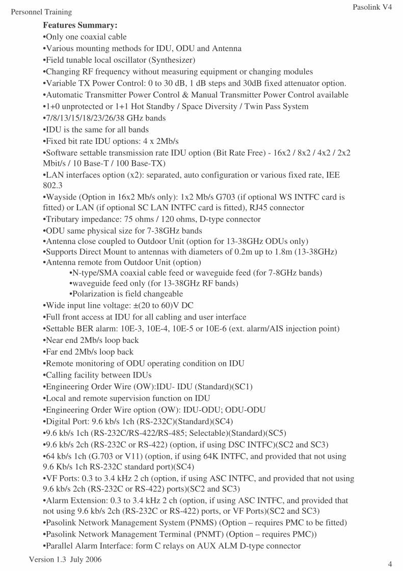
Pasolink V41+0 Link
13-38GHz ODU is shown
Pasolink V4 1+0 IDU is shown
850MHz
-43V DC
10MHz MON
450kHz OW
70MHz
10MHz MON
468kHz OW
____________________________________________________________
____________________________________________________________
____________________________________________________________
____________________________________________________________
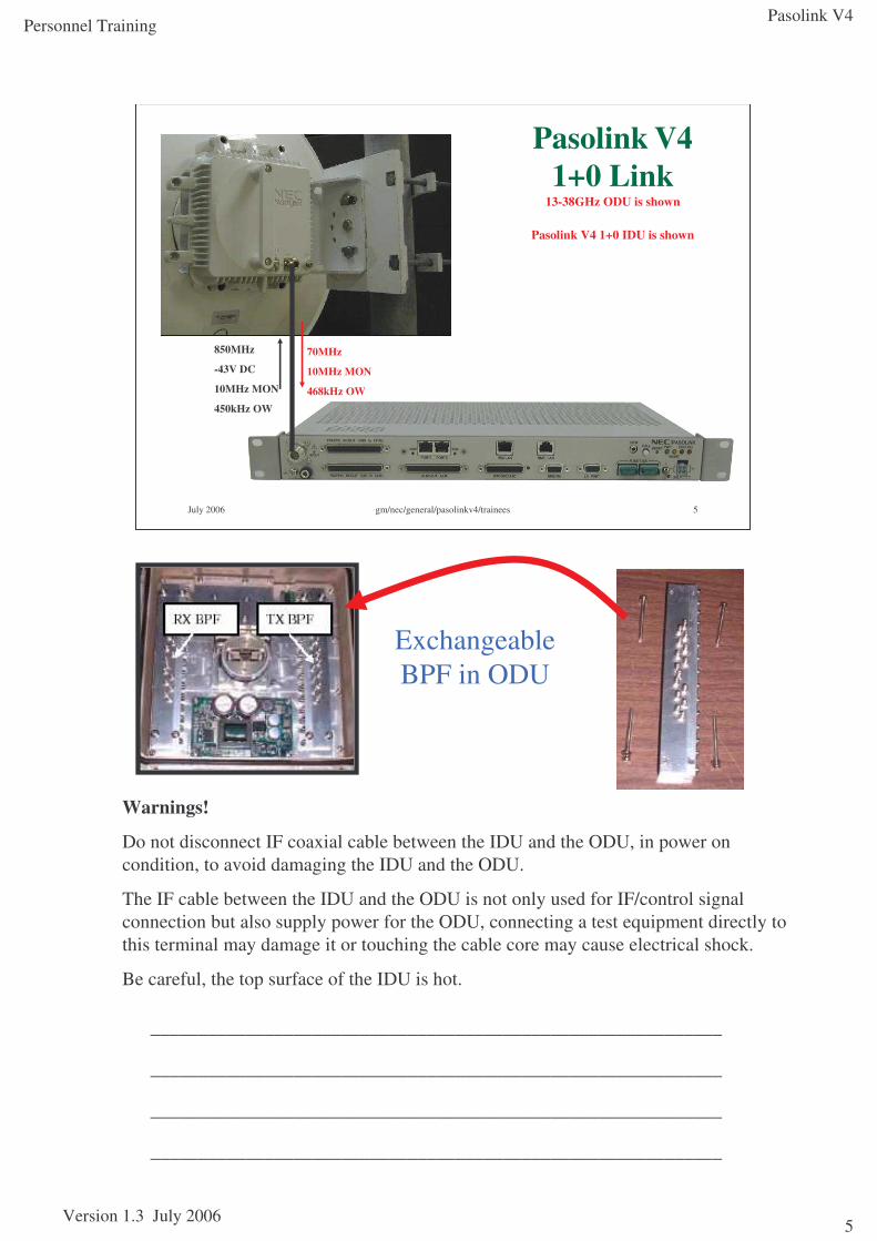
Exchangeable BPF in ODU
Warnings!
Do not disconnect IF coaxial cable between the IDU and the ODU, in power on condition, to avoid damaging the IDU and the ODU.
The IF cable between the IDU and the ODU is not only used for IF/control signal connection but also supply power for the ODU, connecting a test equipment directly to this terminal may damage it or touching the cable core may cause electrical shock.
Be careful, the top surface of the IDU is hot.
Pasolink V4
Version 1.3 July 2006
Personnel Training
6
July 2006 gm/nec/general/pasolinkv4/trainees 6
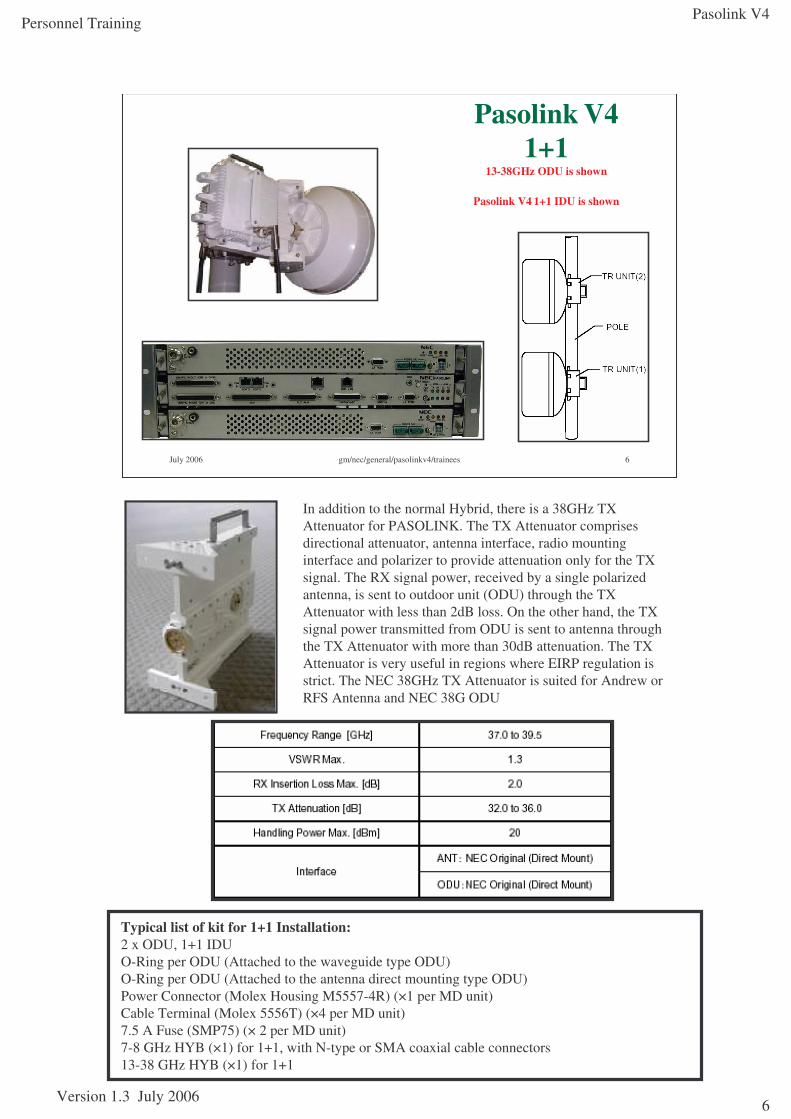
Pasolink V4 1+1
13-38GHz ODU is shown
Pasolink V4 1+1 IDU is shown
____________________________________________________________
____________________________________________________________
____________________________________________________________
____________________________________________________________
In addition to the normal Hybrid, there is a 38GHz TX Attenuator for PASOLINK. The TX Attenuator comprises directional attenuator, antenna interface, radio mounting interface and polarizer to provide attenuation only for the TX signal. The RX signal power, received by a single polarized antenna, is sent to outdoor unit (ODU) through the TX Attenuator with less than 2dB loss. On the other hand, the TX signal power transmitted from ODU is sent to antenna through the TX Attenuator with more than 30dB attenuation. The TX Attenuator is very useful in regions where EIRP regulation is strict. The NEC 38GHz TX Attenuator is suited for Andrew or RFS Antenna and NEC 38G ODU
Specification for 38G TX AttenuatorTypical list of kit for 1+1 Installation:2 x ODU, 1+1 IDUO-Ring per ODU (Attached to the waveguide type ODU)O-Ring per ODU (Attached to the antenna direct mounting type ODU)Power Connector (Molex Housing M5557-4R) (×1 per MD unit)Cable Terminal (Molex 5556T) (×4 per MD unit)7.5 A Fuse (SMP75) (× 2 per MD unit)7-8 GHz HYB (×1) for 1+1, with N-type or SMA coaxial cable connectors13-38 GHz HYB (×1) for 1+1
Pasolink V4
Version 1.3 July 2006
Personnel Training
7
July 2006 gm/nec/general/pasolinkv4/trainees 7
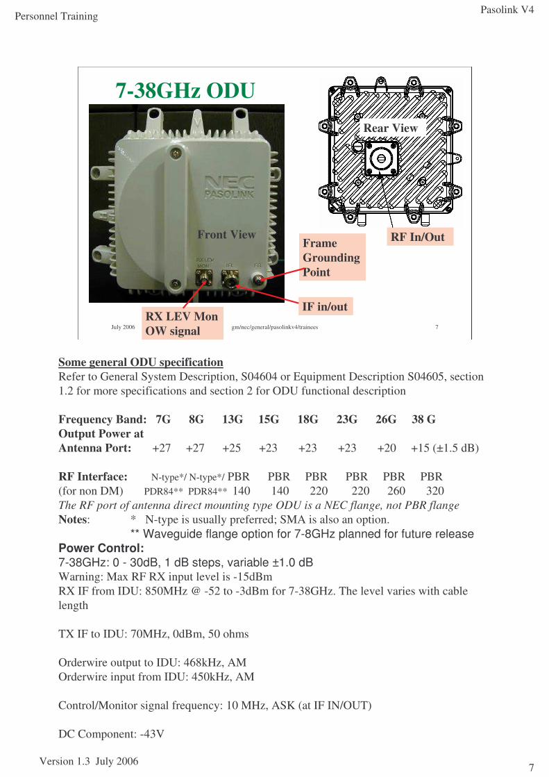
7-38GHz ODU
IF in/outRX LEV Mon OW signal
Frame Grounding Point
Front View
Rear View
RF In/Out
Some general ODU specification Refer to General System Description, S04604 or Equipment Description S04605, section 1.2 for more specifications and section 2 for ODU functional description
Frequency Band: 7G 8G 13G 15G 18G 23G 26G 38 GOutput Power atAntenna Port: +27 +27 +25 +23 +23 +23 +20 +15 (±1.5 dB)
RF Interface: N-type*/ N-type*/ PBR PBR PBR PBR PBR PBR(for non DM) PDR84** PDR84** 140 140 220 220 260 320The RF port of antenna direct mounting type ODU is a NEC flange, not PBR flangeNotes: * N-type is usually preferred; SMA is also an option.
** Waveguide flange option for 7-8GHz planned for future releasePower Control:7-38GHz: 0 - 30dB, 1 dB steps, variable ±1.0 dBWarning: Max RF RX input level is -15dBmRX IF from IDU: 850MHz @ -52 to -3dBm for 7-38GHz. The level varies with cable length
TX IF to IDU: 70MHz, 0dBm, 50 ohms
Orderwire output to IDU: 468kHz, AMOrderwire input from IDU: 450kHz, AM
Control/Monitor signal frequency: 10 MHz, ASK (at IF IN/OUT)
DC Component: -43V
Pasolink V4
Version 1.3 July 2006
Personnel Training
8
July 2006 gm/nec/general/pasolinkv4/trainees 8
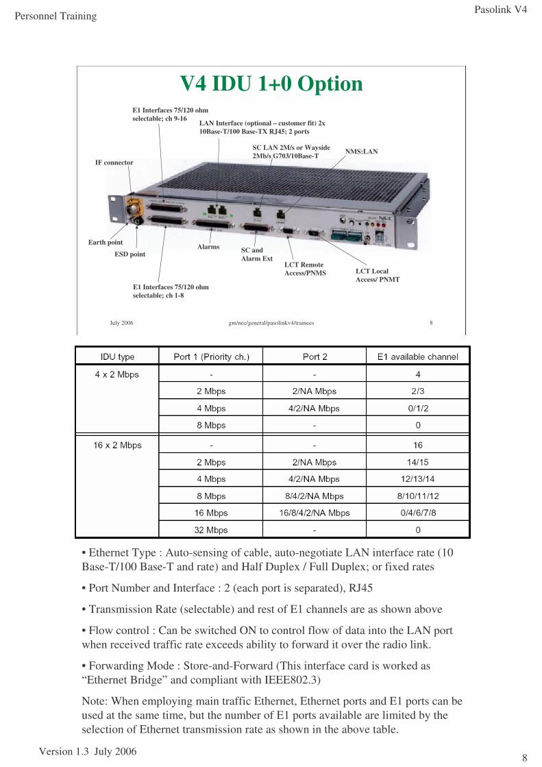
V4 IDU 1+0 Option
E1 Interfaces 75/120 ohm selectable; ch 1-8
LAN Interface (optional – customer fit) 2x 10Base-T/100 Base-TX RJ45; 2 ports
Earth point
ESD point
IF connector
E1 Interfaces 75/120 ohm selectable; ch 9-16
Alarms SC and Alarm Ext
SC LAN 2M/s or Wayside 2Mb/s G703/10Base-T NMS:LAN
LCT Local Access/ PNMT
LCT Remote Access/PNMS
• Ethernet Type : Auto-sensing of cable, auto-negotiate LAN interface rate (10 Base-T/100 Base-T and rate) and Half Duplex / Full Duplex; or fixed rates
• Port Number and Interface : 2 (each port is separated), RJ45
• Transmission Rate (selectable) and rest of E1 channels are as shown above
• Flow control : Can be switched ON to control flow of data into the LAN port when received traffic rate exceeds ability to forward it over the radio link.
• Forwarding Mode : Store-and-Forward (This interface card is worked as “Ethernet Bridge” and compliant with IEEE802.3)
Note: When employing main traffic Ethernet, Ethernet ports and E1 ports can be used at the same time, but the number of E1 ports available are limited by the selection of Ethernet transmission rate as shown in the above table.
Pasolink V4
Version 1.3 July 2006
Personnel Training
9
July 2006 gm/nec/general/pasolinkv4/trainees 9
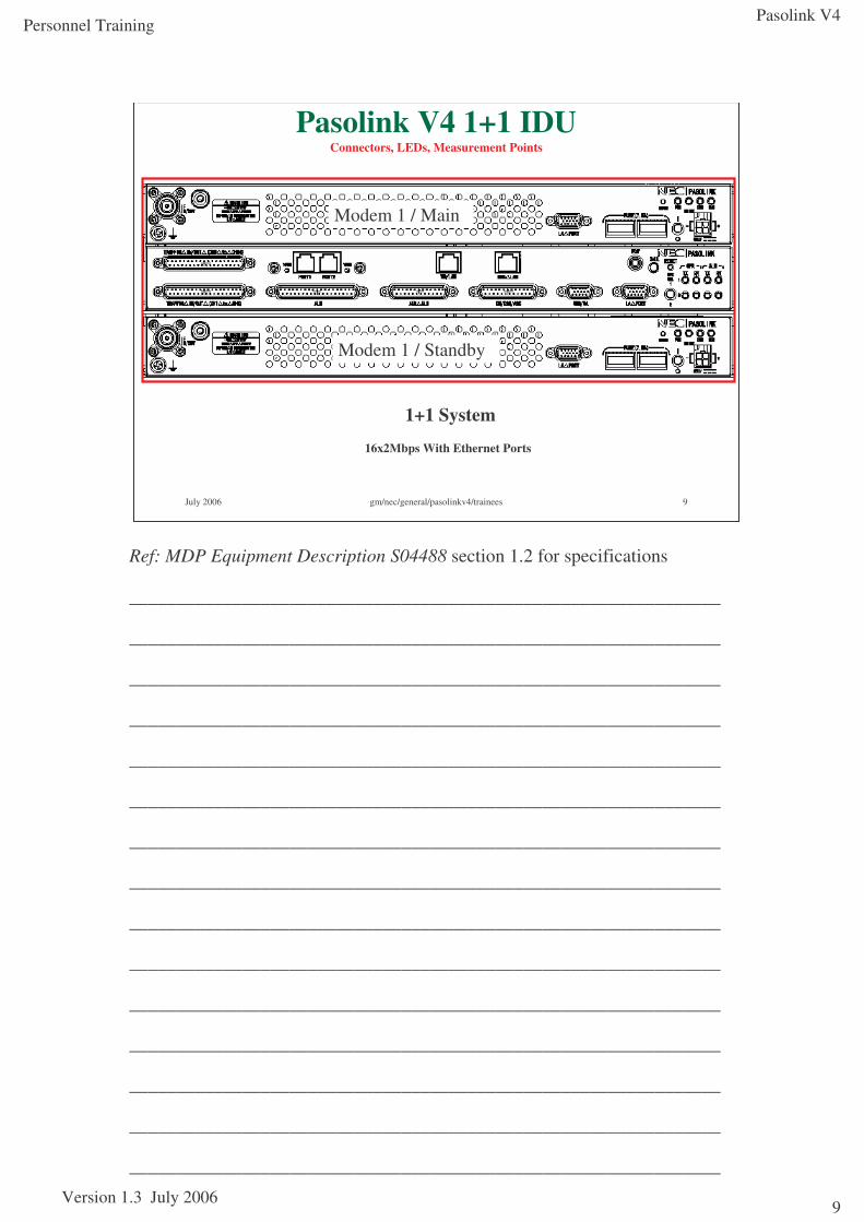
Pasolink V4 1+1 IDUConnectors, LEDs, Measurement Points
1+1 System
16x2Mbps With Ethernet Ports
Modem 1 / Main
Modem 1 / Standby
Ref: MDP Equipment Description S04488 section 1.2 for specifications
_______________________________________________________________
_______________________________________________________________
_______________________________________________________________
_______________________________________________________________
_______________________________________________________________
_______________________________________________________________
_______________________________________________________________
_______________________________________________________________
_______________________________________________________________
_______________________________________________________________
_______________________________________________________________
_______________________________________________________________
_______________________________________________________________
_______________________________________________________________
_______________________________________________________________
Pasolink V4
Version 1.3 July 2006
Personnel Training
10
July 2006 gm/nec/general/pasolinkv4/trainees 10
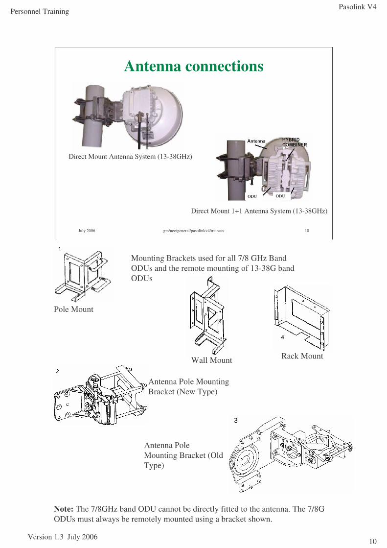
Antenna connections
Direct Mount 1+1 Antenna System (13-38GHz)
Direct Mount Antenna System (13-38GHz)
ODU ODU
Note: The 7/8GHz band ODU cannot be directly fitted to the antenna. The 7/8G ODUs must always be remotely mounted using a bracket shown.
Mounting Brackets used for all 7/8 GHz Band ODUs and the remote mounting of 13-38G band ODUs
Antenna Pole Mounting Bracket (New Type)
Antenna Pole Mounting Bracket (Old Type)
Pole Mount
Wall Mount Rack Mount
Pasolink V4
Version 1.3 July 2006
Personnel Training
11
July 2006 gm/nec/general/pasolinkv4/trainees 11
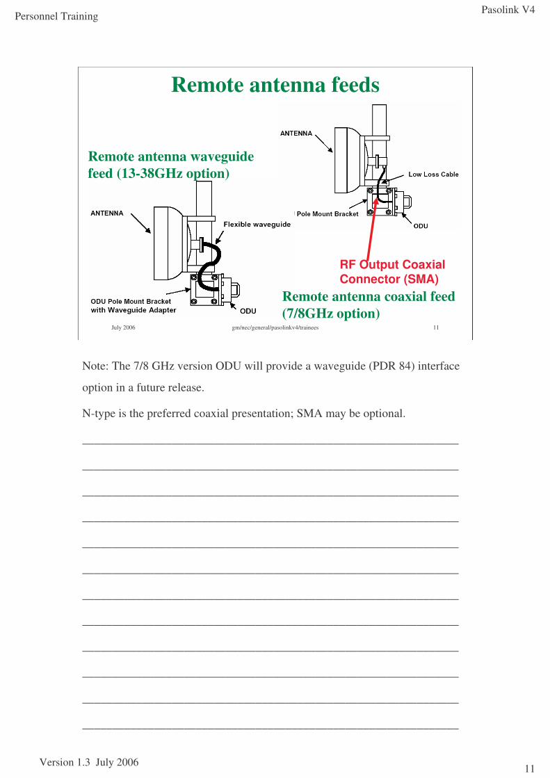
Remote antenna feeds
RF Output Coaxial Connector (SMA)
Remote antenna coaxial feed (7/8GHz option)
Remote antenna waveguide feed (13-38GHz option)
Note: The 7/8 GHz version ODU will provide a waveguide (PDR 84) interface
option in a future release.
N-type is the preferred coaxial presentation; SMA may be optional.
_______________________________________________________________
_______________________________________________________________
_______________________________________________________________
_______________________________________________________________
_______________________________________________________________
_______________________________________________________________
_______________________________________________________________
_______________________________________________________________
_______________________________________________________________
_______________________________________________________________
_______________________________________________________________
_______________________________________________________________
Pasolink V4
Version 1.3 July 2006
Personnel Training
12
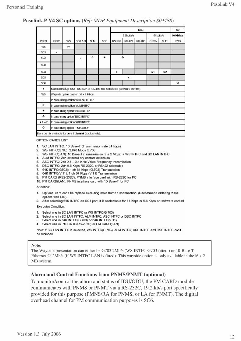
Alarm and Control Functions from PNMS/PNMT (optional)To monitor/control the alarm and status of IDU/ODU, the PM CARD module communicates with PNMS or PNMT via a RS-232C, 19.2 kb/s port specifically provided for this purpose (PMNS/RA for PNMS, or LA for PNMT). The digital overhead channel for PM communication purposes is SC6.
Pasolink-P V4 SC options (Ref: MDP Equipment Description S04488)
Note:The Wayside presentation can either be G703 2Mb/s (WS INTFC G703 fitted ) or 10-Base T Ethernet @ 2Mb/s (if WS INTFC LAN is fitted). This wayside option is only available in the16 x 2 MB system.
Pasolink V4
Version 1.3 July 2006
Personnel Training
13
July 2006 gm/nec/general/pasolinkv4/trainees 13
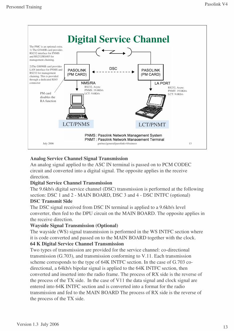
Digital Service Channel
LCT/PNMS LCT/PNMT
PM card disables the RA function
The PMC is an optional extra. 1) The G5440B card provides RS232 interface for PNMS and RS232/RS485 for management chaining.
2)The G8896B card provides LAN interface for PNMS and RS232 for management chaining. This is provided through a dedicated RJ45 connector
RS232, Async PNMS: 19.6Kb/s LCT: 9.6Kb/s
RS232, Async PNMT: 19.6Kb/s LCT: 9.6Kb/s
Analog Service Channel Signal TransmissionAn analog signal applied to the ASC IN terminal is passed on to PCM CODEC circuit and converted into a digital signal. The opposite applies in the receive direction.Digital Service Channel TransmissionThe 9.6kb/s digital service channel (DSC) transmission is performed at the following section: DSC 1 and 2 - MAIN BOARD, DSC 3 and 4 - DSC INTFC (optional)DSC Transmit SideThe DSC signal received from DSC IN terminal is applied to a 9.6kb/s level converter, then fed to the DPU circuit on the MAIN BOARD. The opposite applies in the receive direction.Wayside Signal Transmission (Optional)The wayside (WS) signal transmission is performed in the WS INTFC section where it is code converted and passed on to the MAIN BOARD together with the clock.64 K Digital Service Channel TransmissionTwo types of transmission are provided for the service channel: co-directional transmission (G.703), and transmission conforming to V.11. Each transmission scheme corresponds to the type of 64K INTFC section. In the case of G.703 co-directional, a 64kb/s bipolar signal is applied to the 64K INTFC section, then converted and inserted into the radio frame. The process of RX side is the reverse of the process of the TX side. In the case of V11 the data signal and clock signal are entered into 64K INTFC section and is converted into a format for the radio transmission and fed to the MAIN BOARD The process of RX side is the reverse of the process of the TX side.
Pasolink V4
Version 1.3 July 2006
Personnel Training
14
July 2006 gm/nec/general/pasolinkv4/trainees 14
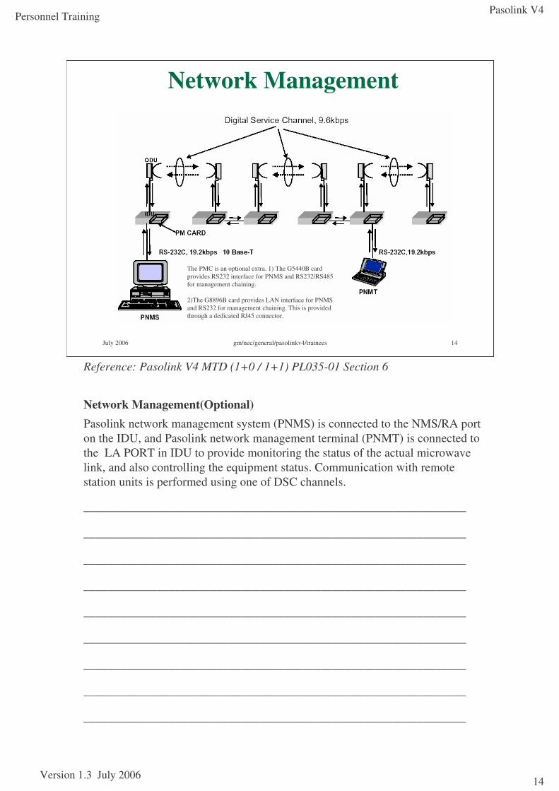
Network Management
The PMC is an optional extra. 1) The G5440B card provides RS232 interface for PNMS and RS232/RS485 for management chaining.
2)The G8896B card provides LAN interface for PNMS and RS232 for management chaining. This is provided through a dedicated RJ45 connector.
Reference: Pasolink V4 MTD (1+0 / 1+1) PL035-01 Section 6
Network Management(Optional)Pasolink network management system (PNMS) is connected to the NMS/RA port on the IDU, and Pasolink network management terminal (PNMT) is connected to the LA PORT in IDU to provide monitoring the status of the actual microwave link, and also controlling the equipment status. Communication with remote station units is performed using one of DSC channels.
_______________________________________________________________
_______________________________________________________________
_______________________________________________________________
_______________________________________________________________
_______________________________________________________________
_______________________________________________________________
_______________________________________________________________
_______________________________________________________________
_______________________________________________________________
Pasolink V4
Version 1.3 July 2006
Personnel Training
15
July 2006 gm/nec/general/pasolinkv4/trainees 15
Module 2Installation
ObjectivesAt the end of this module, you will be able to do the following:
•Describe how to physically install the Pasolink V4 equipment for both the close coupled and remote antenna configurations
•Describe the cabling required for the installation of the Pasolink V4
•State the specialist tools that are required to install the equipment
•Describe how to physically upgrade a 1+0 link to a 1+1 link and vice versa
References:Pasolink V4 User (Instruction) Manual ROI-S0xxxx-051E
Abbreviations ROI-S04491-052EGeneral System Description ROI-S04604-052EMeasurement Procedure ROI-S04607-054ETRP Equipment Description ROI-S04605-054ERadio Frequency Assignment (n GHz) ROI-various-05xE
MDP Equipment Description ROI-S04488-058EInstallation and Initial Lineup ROI-S04606-054E
Pasolink V4 Sub-band Change Procedure
Pasolink V4 MTD (1+0 / 1+1) PL035-01
Pasolink V4
Version 1.3 July 2006
Personnel Training
16
July 2006 gm/nec/general/pasolinkv4/trainees 16
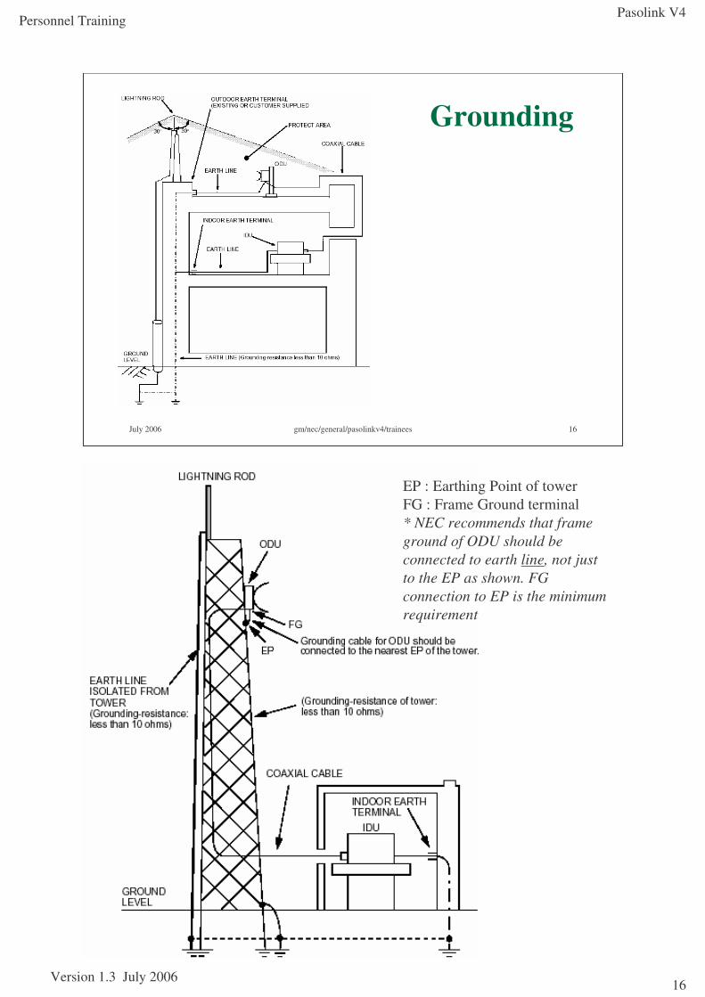
Grounding
EP : Earthing Point of towerFG : Frame Ground terminal* NEC recommends that frame ground of ODU should be connected to earth line, not just to the EP as shown. FG connection to EP is the minimum requirement
Pasolink V4
Version 1.3 July 2006
Personnel Training
17
July 2006 gm/nec/general/pasolinkv4/trainees 17
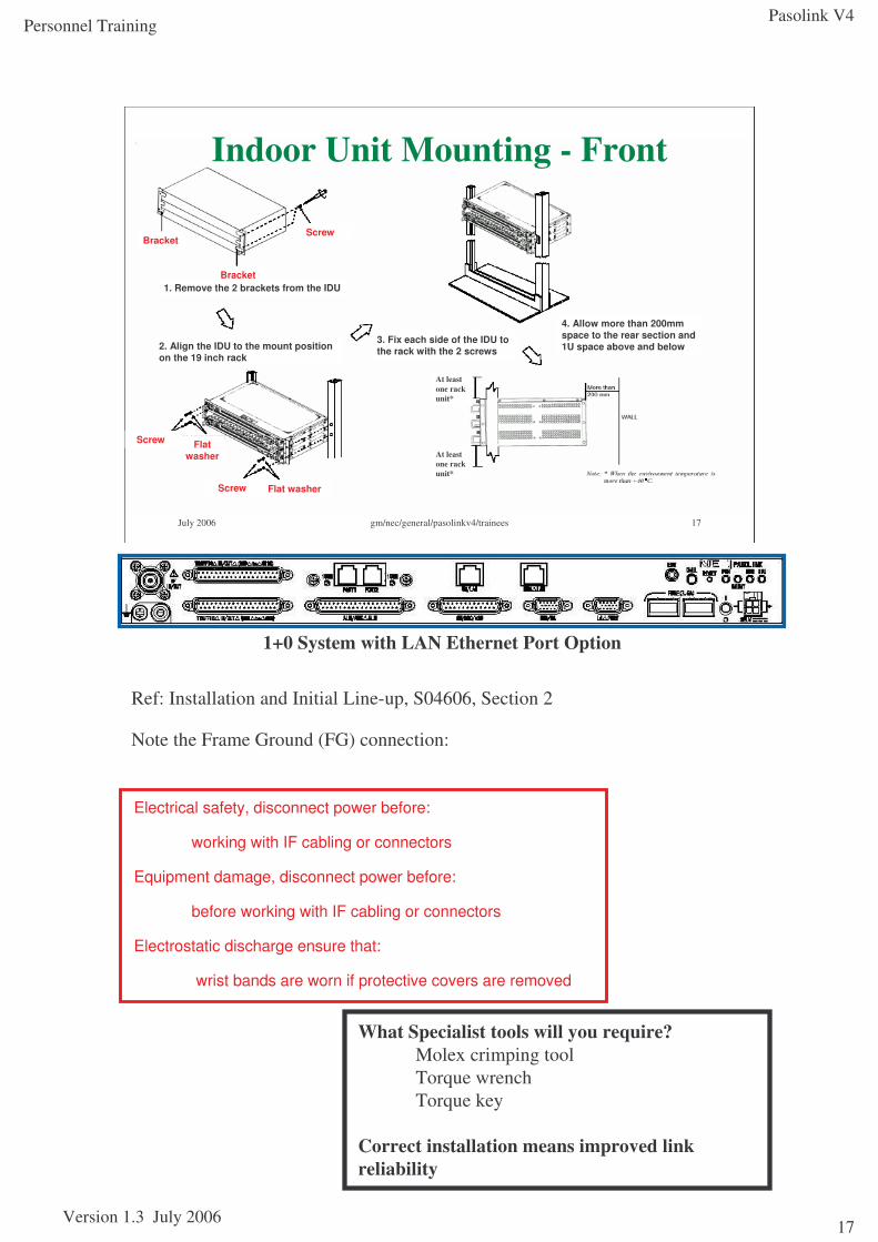
Indoor Unit Mounting - Front
1. Remove the 2 brackets from the IDUBracket
BracketScrew
2. Align the IDU to the mount position on the 19 inch rack
4. Allow more than 200mm space to the rear section and 1U space above and below
3. Fix each side of the IDU to the rack with the 2 screws
Screw
Screw Flat washer
Flat washer
At leastone rack unit*
At leastone rack unit*
Ref: Installation and Initial Line-up, S04606, Section 2
Note the Frame Ground (FG) connection:
1+0 System with LAN Ethernet Port Option
Electrical safety, disconnect power before:
working with IF cabling or connectors
Equipment damage, disconnect power before:
before working with IF cabling or connectors
Electrostatic discharge ensure that:
wrist bands are worn if protective covers are removed
What Specialist tools will you require?Molex crimping toolTorque wrenchTorque key
Correct installation means improved link reliability
Pasolink V4
Version 1.3 July 2006
Personnel Training
18
July 2006 gm/nec/general/pasolinkv4/trainees 18
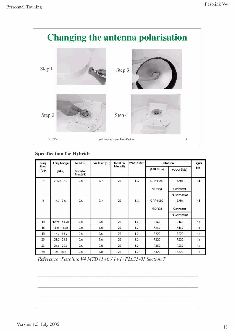
Changing the antenna polarisation
Step 1
Step 4
Step 3
Step 2
_______________________________________________________________
_______________________________________________________________
_______________________________________________________________
_______________________________________________________________
Specification for Hybrid:
Reference: Pasolink V4 MTD (1+0 / 1+1) PL035-01 Section 7
Pasolink V4
Version 1.3 July 2006
Personnel Training
19
July 2006 gm/nec/general/pasolinkv4/trainees 19
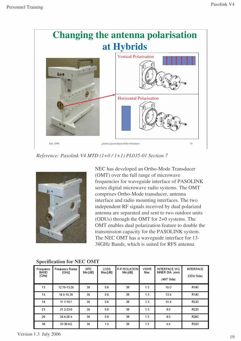
Changing the antenna polarisation at Hybrids
Horizontal Polarisation
Vertical Polarisation
Reference: Pasolink V4 MTD (1+0 / 1+1) PL035-01 Section 7
NEC has developed an Ortho-Mode Transducer (OMT) over the full range of microwave frequencies for waveguide interface of PASOLINK series digital microwave radio systems. The OMT comprises Ortho-Mode transducer, antenna interface and radio mounting interfaces. The two independent RF signals received by dual polarized antenna are separated and sent to two outdoor units (ODUs) through the OMT for 2+0 systems. The OMT enables dual polarization feature to double the transmission capacity for the PASOLINK system. The NEC OMT has a waveguide interface for 13-38GHz Bands, which is suited for RFS antenna
Specification for NEC OMT
Pasolink V4
Version 1.3 July 2006
Personnel Training
20
July 2006 gm/nec/general/pasolinkv4/trainees 20
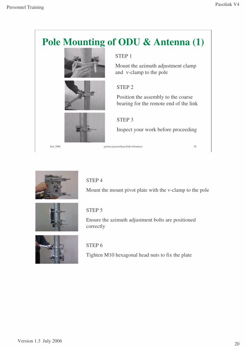
Pole Mounting of ODU & Antenna (1)STEP 1
Mount the azimuth adjustment clamp and v-clamp to the pole
STEP 2
Position the assembly to the coarse bearing for the remote end of the link
STEP 3
Inspect your work before proceeding
STEP 4
Mount the mount pivot plate with the v-clamp to the pole
STEP 5
Ensure the azimuth adjustment bolts are positioned correctly
STEP 6
Tighten M10 hexagonal head nuts to fix the plate
Pasolink V4
Version 1.3 July 2006
Personnel Training
21
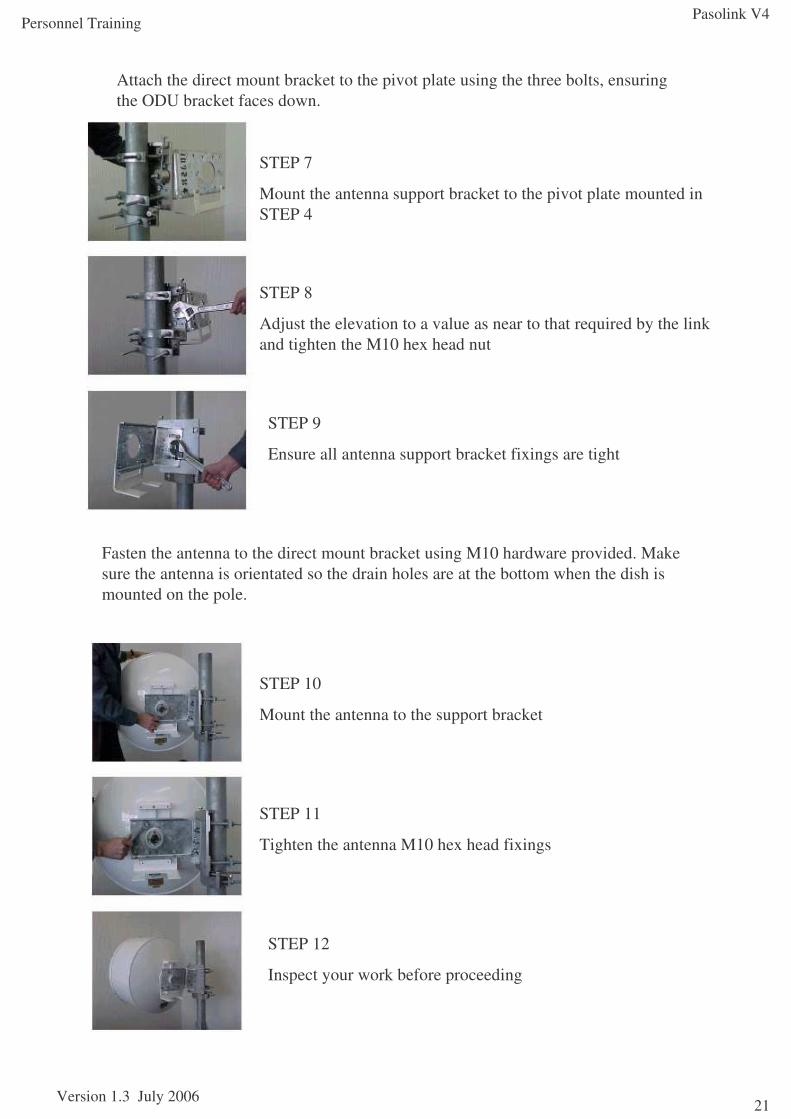
Attach the direct mount bracket to the pivot plate using the three bolts, ensuring the ODU bracket faces down.
STEP 7
Mount the antenna support bracket to the pivot plate mounted in STEP 4
STEP 8
Adjust the elevation to a value as near to that required by the link and tighten the M10 hex head nut
STEP 9
Ensure all antenna support bracket fixings are tight
Fasten the antenna to the direct mount bracket using M10 hardware provided. Make sure the antenna is orientated so the drain holes are at the bottom when the dish is mounted on the pole.
STEP 10
Mount the antenna to the support bracket
STEP 11
Tighten the antenna M10 hex head fixings
STEP 12
Inspect your work before proceeding
Pasolink V4
Version 1.3 July 2006
Personnel Training
22
July 2006 gm/nec/general/pasolinkv4/trainees 22
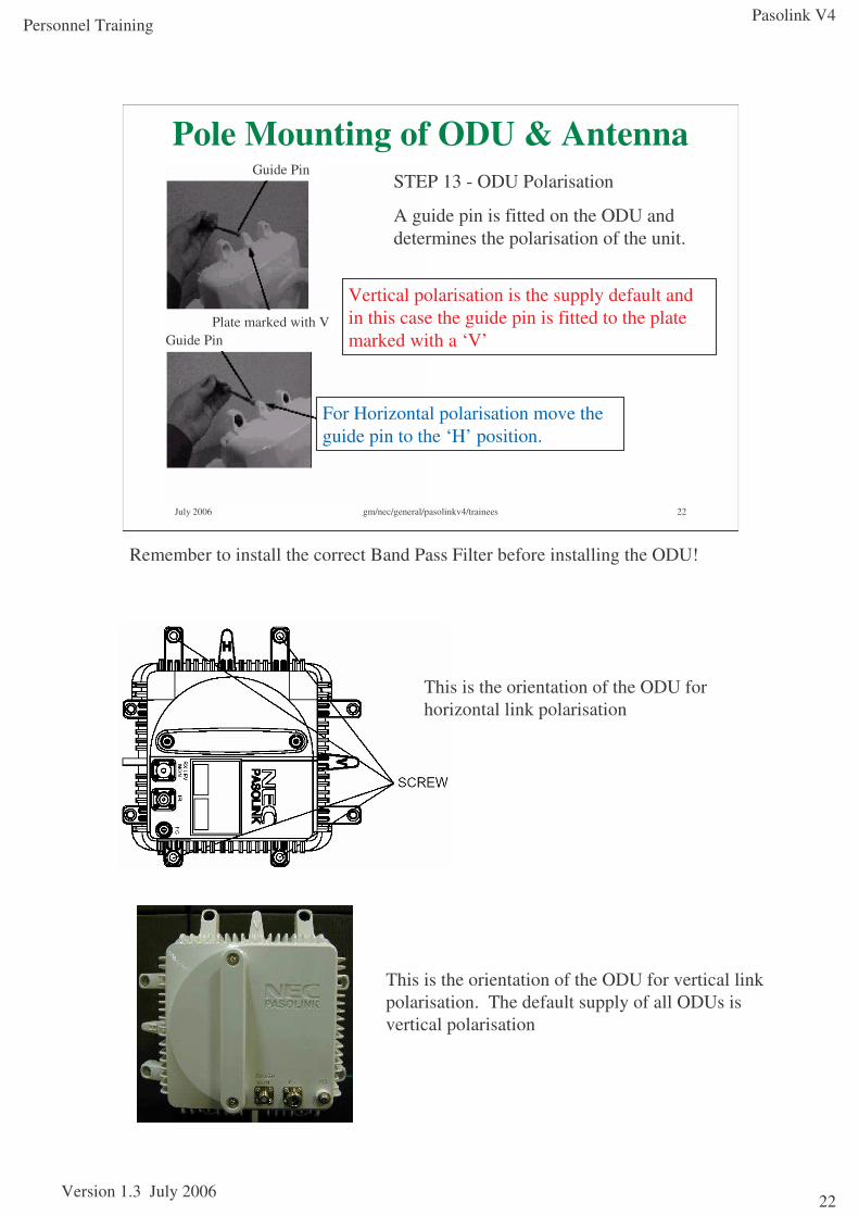
Pole Mounting of ODU & AntennaSTEP 13 - ODU Polarisation
A guide pin is fitted on the ODU and determines the polarisation of the unit.
For Horizontal polarisation move the guide pin to the ‘H’ position.
Vertical polarisation is the supply default and in this case the guide pin is fitted to the plate marked with a ‘V’Guide Pin
Plate marked with V
Guide Pin
This is the orientation of the ODU for vertical link polarisation. The default supply of all ODUs is vertical polarisation
This is the orientation of the ODU for horizontal link polarisation
Remember to install the correct Band Pass Filter before installing the ODU!
Pasolink V4
Version 1.3 July 2006
Personnel Training
23
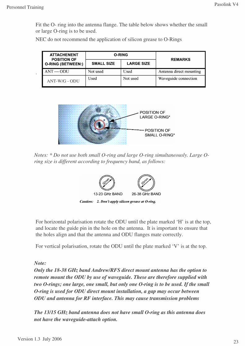
Fit the O- ring into the antenna flange. The table below shows whether the small or large O-ring is to be used.
NEC do not recommend the application of silicon grease to O-Rings
.
For horizontal polarisation rotate the ODU until the plate marked ‘H’ is at the top, and locate the guide pin in the hole on the antenna. It is important to ensure that the holes align and that the antenna and ODU flanges mate correctly.
For vertical polarisation, rotate the ODU until the plate marked ‘V’ is at the top.
Notes: * Do not use both small O-ring and large O-ring simultaneously. Large O-ring size is different according to frequency band, as follows:
ANT-W/G - ODU
Note:Only the 18-38 GHz band Andrew/RFS direct mount antenna has the option to remote mount the ODU by use of waveguide. These are therefore supplied with two O-rings; one large, one small, but only one O-ring is to be used. If the small O-ring is used for ODU direct mount installation, a gap may occur between ODU and antenna for RF interface. This may cause transmission problems
The 13/15 GHz band antenna does not have small O-ring as this antenna does not have the waveguide-attach option.
Pasolink V4
Version 1.3 July 2006
Personnel Training
24
July 2006 gm/nec/general/pasolinkv4/trainees 24
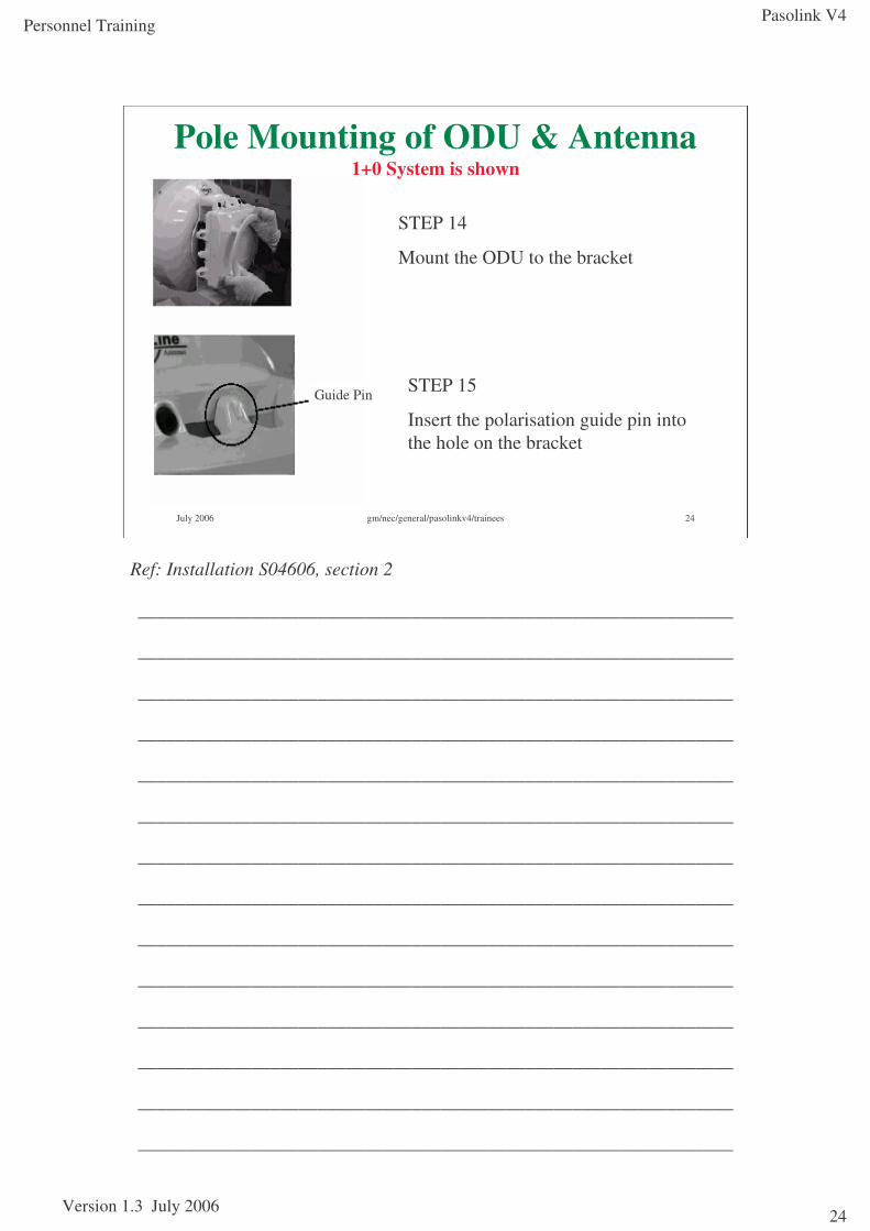
Pole Mounting of ODU & Antenna1+0 System is shown
STEP 14
Mount the ODU to the bracket
STEP 15
Insert the polarisation guide pin into the hole on the bracket
Guide Pin
Ref: Installation S04606, section 2
_______________________________________________________________
_______________________________________________________________
_______________________________________________________________
_______________________________________________________________
_______________________________________________________________
_______________________________________________________________
_______________________________________________________________
_______________________________________________________________
_______________________________________________________________
_______________________________________________________________
_______________________________________________________________
_______________________________________________________________
_______________________________________________________________
_______________________________________________________________
Pasolink V4
Version 1.3 July 2006
Personnel Training
25
July 2006 gm/nec/general/pasolinkv4/trainees 25
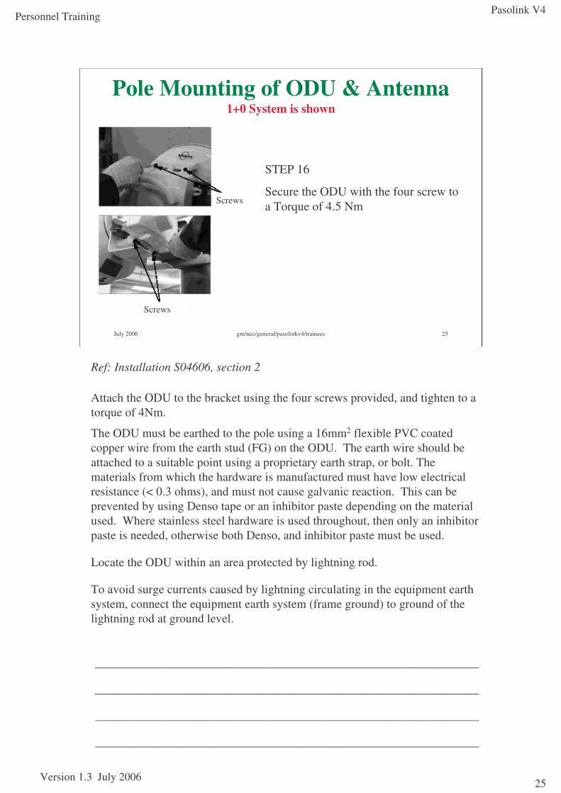
Pole Mounting of ODU & Antenna1+0 System is shown
STEP 16
Secure the ODU with the four screw to a Torque of 4.5 Nm
Screws
Screws
_______________________________________________________________
_______________________________________________________________
_______________________________________________________________
_______________________________________________________________
Ref: Installation S04606, section 2
Attach the ODU to the bracket using the four screws provided, and tighten to a torque of 4Nm.
The ODU must be earthed to the pole using a 16mm2 flexible PVC coated copper wire from the earth stud (FG) on the ODU. The earth wire should be attached to a suitable point using a proprietary earth strap, or bolt. The materials from which the hardware is manufactured must have low electrical resistance (< 0.3 ohms), and must not cause galvanic reaction. This can be prevented by using Denso tape or an inhibitor paste depending on the material used. Where stainless steel hardware is used throughout, then only an inhibitor paste is needed, otherwise both Denso, and inhibitor paste must be used.
Locate the ODU within an area protected by lightning rod.
To avoid surge currents caused by lightning circulating in the equipment earth system, connect the equipment earth system (frame ground) to ground of the lightning rod at ground level.
Pasolink V4
Version 1.3 July 2006
Personnel Training
26
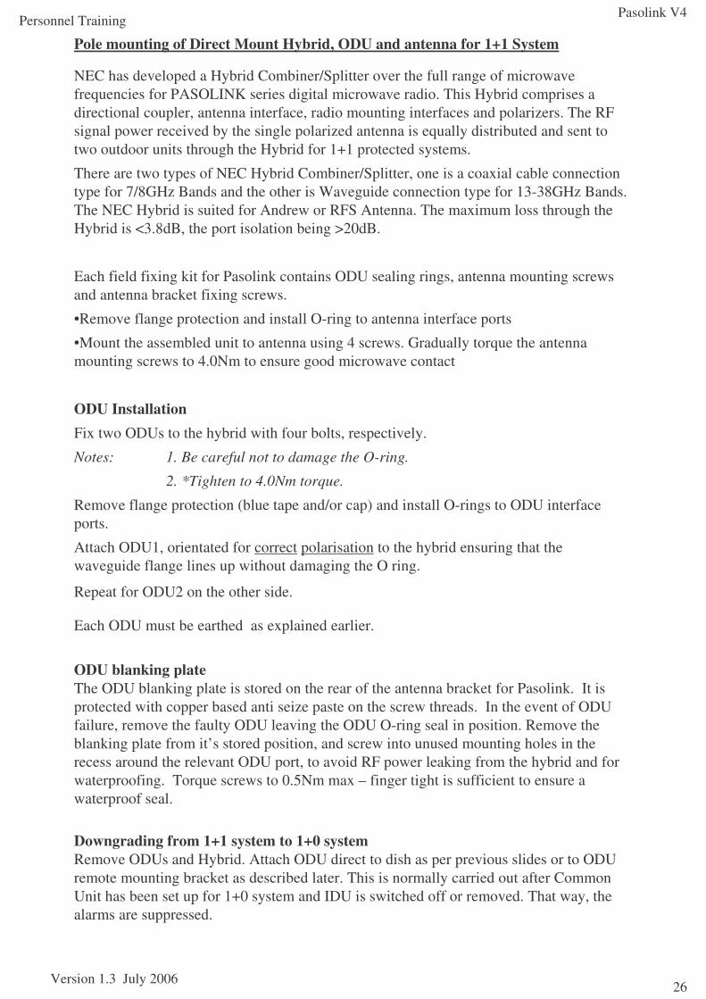
Pole mounting of Direct Mount Hybrid, ODU and antenna for 1+1 System
NEC has developed a Hybrid Combiner/Splitter over the full range of microwave frequencies for PASOLINK series digital microwave radio. This Hybrid comprises a directional coupler, antenna interface, radio mounting interfaces and polarizers. The RF signal power received by the single polarized antenna is equally distributed and sent to two outdoor units through the Hybrid for 1+1 protected systems.
There are two types of NEC Hybrid Combiner/Splitter, one is a coaxial cable connection type for 7/8GHz Bands and the other is Waveguide connection type for 13-38GHz Bands. The NEC Hybrid is suited for Andrew or RFS Antenna. The maximum loss through the Hybrid is <3.8dB, the port isolation being >20dB.
Each field fixing kit for Pasolink contains ODU sealing rings, antenna mounting screws and antenna bracket fixing screws.
•Remove flange protection and install O-ring to antenna interface ports
•Mount the assembled unit to antenna using 4 screws. Gradually torque the antenna mounting screws to 4.0Nm to ensure good microwave contact
ODU InstallationFix two ODUs to the hybrid with four bolts, respectively.
Notes: 1. Be careful not to damage the O-ring.
2. *Tighten to 4.0Nm torque.
Remove flange protection (blue tape and/or cap) and install O-rings to ODU interface ports.
Attach ODU1, orientated for correct polarisation to the hybrid ensuring that the waveguide flange lines up without damaging the O ring.
Repeat for ODU2 on the other side.
Each ODU must be earthed as explained earlier.
ODU blanking plateThe ODU blanking plate is stored on the rear of the antenna bracket for Pasolink. It is protected with copper based anti seize paste on the screw threads. In the event of ODU failure, remove the faulty ODU leaving the ODU O-ring seal in position. Remove the blanking plate from it’s stored position, and screw into unused mounting holes in the recess around the relevant ODU port, to avoid RF power leaking from the hybrid and for waterproofing. Torque screws to 0.5Nm max – finger tight is sufficient to ensure a waterproof seal.
Downgrading from 1+1 system to 1+0 systemRemove ODUs and Hybrid. Attach ODU direct to dish as per previous slides or to ODU remote mounting bracket as described later. This is normally carried out after Common Unit has been set up for 1+0 system and IDU is switched off or removed. That way, the alarms are suppressed.
Pasolink V4
Version 1.3 July 2006
Personnel Training
27
July 2006 gm/nec/general/pasolinkv4/trainees 27
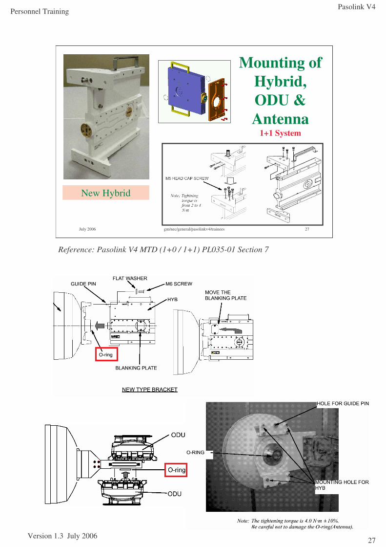
Mounting of Hybrid, ODU & Antenna
1+1 System
New Hybrid
Reference: Pasolink V4 MTD (1+0 / 1+1) PL035-01 Section 7
Pasolink V4
Version 1.3 July 2006
Personnel Training
28
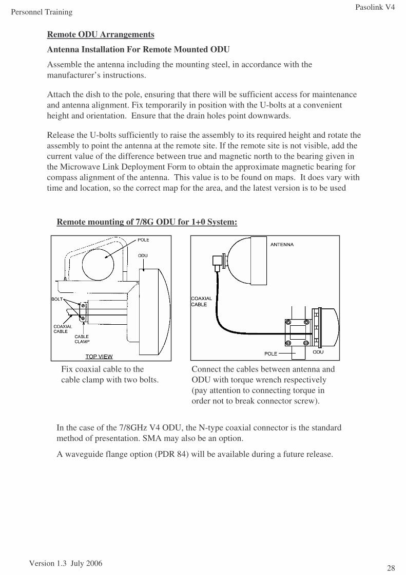
Remote ODU Arrangements
Antenna Installation For Remote Mounted ODU
Assemble the antenna including the mounting steel, in accordance with the manufacturer’s instructions.
Attach the dish to the pole, ensuring that there will be sufficient access for maintenance and antenna alignment. Fix temporarily in position with the U-bolts at a convenient height and orientation. Ensure that the drain holes point downwards.
Release the U-bolts sufficiently to raise the assembly to its required height and rotate the assembly to point the antenna at the remote site. If the remote site is not visible, add the current value of the difference between true and magnetic north to the bearing given in the Microwave Link Deployment Form to obtain the approximate magnetic bearing for compass alignment of the antenna. This value is to be found on maps. It does vary with time and location, so the correct map for the area, and the latest version is to be used
Fix coaxial cable to thecable clamp with two bolts.
Connect the cables between antenna and ODU with torque wrench respectively (pay attention to connecting torque in order not to break connector screw).
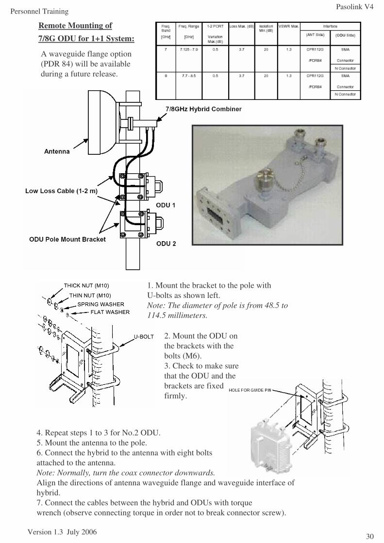
Remote mounting of 7/8G ODU for 1+0 System:
In the case of the 7/8GHz V4 ODU, the N-type coaxial connector is the standard method of presentation. SMA may also be an option.
A waveguide flange option (PDR 84) will be available during a future release.
Pasolink V4
Version 1.3 July 2006
Personnel Training
29
July 2006 gm/nec/general/pasolinkv4/trainees 29
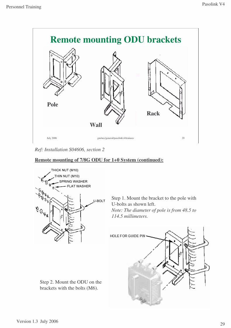
Remote mounting ODU brackets
Pole
Wall
Rack
Step 1. Mount the bracket to the pole withU-bolts as shown left.Note: The diameter of pole is from 48.5 to114.5 millimeters.
Step 2. Mount the ODU on the brackets with the bolts (M6).
Ref: Installation S04606, section 2
Remote mounting of 7/8G ODU for 1+0 System (continued):
Pasolink V4
Version 1.3 July 2006
Personnel Training
30
Remote Mounting of 7/8G ODU for 1+1 System:
1. Mount the bracket to the pole withU-bolts as shown left.Note: The diameter of pole is from 48.5 to114.5 millimeters.
2. Mount the ODU on the brackets with the bolts (M6).3. Check to make sure that the ODU and the brackets are fixed firmly.
4. Repeat steps 1 to 3 for No.2 ODU.5. Mount the antenna to the pole.6. Connect the hybrid to the antenna with eight bolts attached to the antenna.Note: Normally, turn the coax connector downwards.Align the directions of antenna waveguide flange and waveguide interface of hybrid.7. Connect the cables between the hybrid and ODUs with torquewrench (observe connecting torque in order not to break connector screw).
A waveguide flange option (PDR 84) will be available during a future release.
Pasolink V4
Version 1.3 July 2006
Personnel Training
31
July 2006 gm/nec/general/pasolinkv4/trainees 31
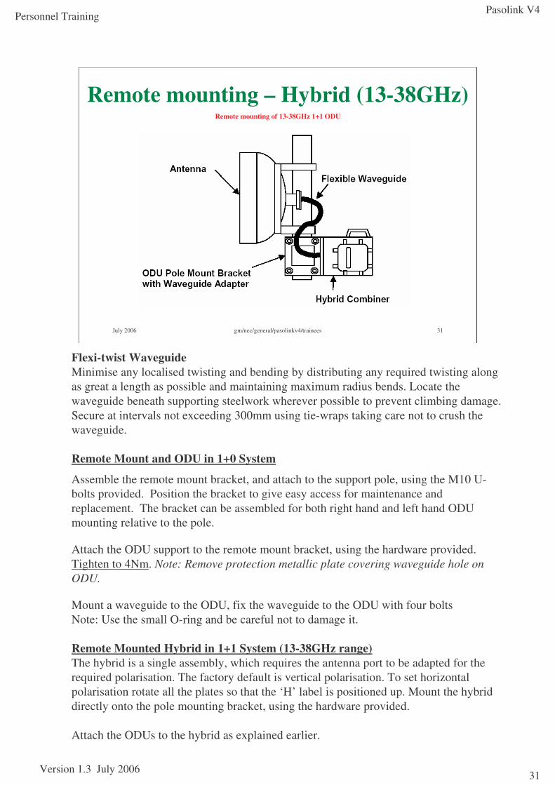
Remote mounting – Hybrid (13-38GHz)Remote mounting of 13-38GHz 1+1 ODU
Flexi-twist WaveguideMinimise any localised twisting and bending by distributing any required twisting along as great a length as possible and maintaining maximum radius bends. Locate the waveguide beneath supporting steelwork wherever possible to prevent climbing damage. Secure at intervals not exceeding 300mm using tie-wraps taking care not to crush the waveguide.
Remote Mount and ODU in 1+0 System
Assemble the remote mount bracket, and attach to the support pole, using the M10 U-bolts provided. Position the bracket to give easy access for maintenance and replacement. The bracket can be assembled for both right hand and left hand ODU mounting relative to the pole.
Attach the ODU support to the remote mount bracket, using the hardware provided. Tighten to 4Nm. Note: Remove protection metallic plate covering waveguide hole on ODU.
Mount a waveguide to the ODU, fix the waveguide to the ODU with four boltsNote: Use the small O-ring and be careful not to damage it.
Remote Mounted Hybrid in 1+1 System (13-38GHz range)The hybrid is a single assembly, which requires the antenna port to be adapted for the required polarisation. The factory default is vertical polarisation. To set horizontal polarisation rotate all the plates so that the ‘H’ label is positioned up. Mount the hybrid directly onto the pole mounting bracket, using the hardware provided.
Attach the ODUs to the hybrid as explained earlier.
Pasolink V4
Version 1.3 July 2006
Personnel Training
32
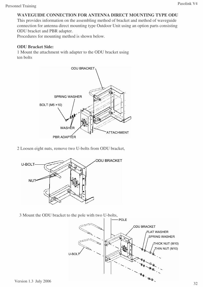
WAVEGUIDE CONNECTION FOR ANTENNA DIRECT MOUNTING TYPE ODUThis provides information on the assembling method of bracket and method of waveguide connection for antenna direct mounting type Outdoor Unit using an option parts consisting ODU bracket and PBR adapter.Procedures for mounting method is shown below.
ODU Bracket Side:1 Mount the attachment with adapter to the ODU bracket usingten bolts
2 Loosen eight nuts, remove two U-bolts from ODU bracket,
3 Mount the ODU bracket to the pole with two U-bolts,
Pasolink V4
Version 1.3 July 2006
Personnel Training
33
July 2006 gm/nec/general/pasolinkv4/trainees 33
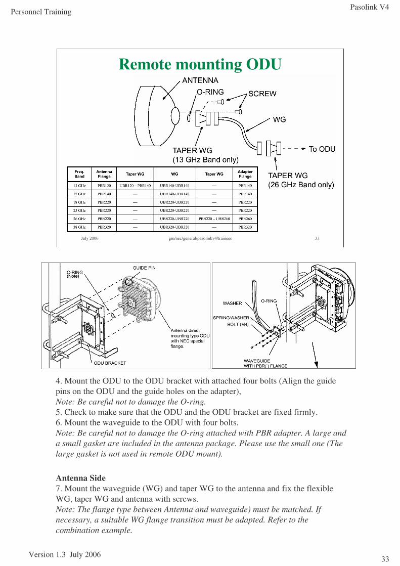
Remote mounting ODU
4. Mount the ODU to the ODU bracket with attached four bolts (Align the guide pins on the ODU and the guide holes on the adapter),Note: Be careful not to damage the O-ring.5. Check to make sure that the ODU and the ODU bracket are fixed firmly.6. Mount the waveguide to the ODU with four bolts.Note: Be careful not to damage the O-ring attached with PBR adapter. A large and a small gasket are included in the antenna package. Please use the small one (The large gasket is not used in remote ODU mount).
Antenna Side7. Mount the waveguide (WG) and taper WG to the antenna and fix the flexible WG, taper WG and antenna with screws.Note: The flange type between Antenna and waveguide) must be matched. If necessary, a suitable WG flange transition must be adapted. Refer to the combination example.
Pasolink V4
Version 1.3 July 2006
Personnel Training
34
July 2006 gm/nec/general/pasolinkv4/trainees 34
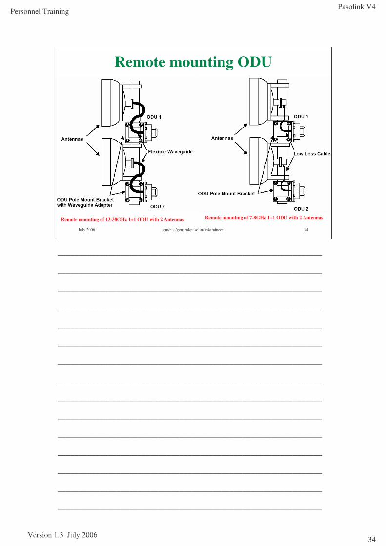
Remote mounting ODU
Remote mounting of 13-38GHz 1+1 ODU with 2 Antennas Remote mounting of 7-8GHz 1+1 ODU with 2 Antennas
_______________________________________________________________
_______________________________________________________________
_______________________________________________________________
_______________________________________________________________
_______________________________________________________________
_______________________________________________________________
_______________________________________________________________
_______________________________________________________________
_______________________________________________________________
_______________________________________________________________
_______________________________________________________________
_______________________________________________________________
_______________________________________________________________
_______________________________________________________________
_______________________________________________________________
Pasolink V4
Version 1.3 July 2006
Personnel Training
35
July 2006 gm/nec/general/pasolinkv4/trainees 35
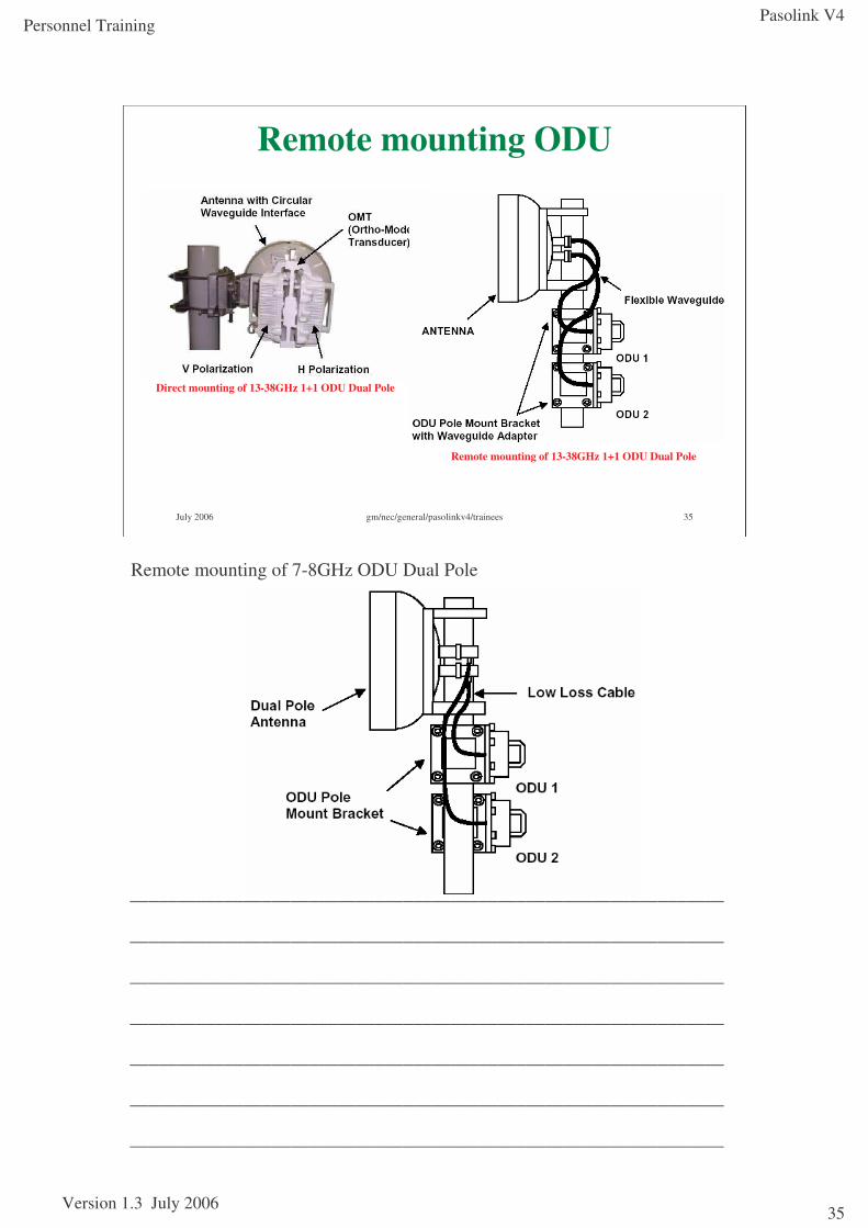
Remote mounting ODU
Direct mounting of 13-38GHz 1+1 ODU Dual Pole
Remote mounting of 13-38GHz 1+1 ODU Dual Pole
Remote mounting of 7-8GHz ODU Dual Pole
_______________________________________________________________
_______________________________________________________________
_______________________________________________________________
_______________________________________________________________
_______________________________________________________________
_______________________________________________________________
_______________________________________________________________
Pasolink V4
Version 1.3 July 2006
Personnel Training
36
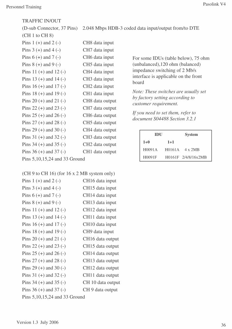
TRAFFIC IN/OUT (D-sub Connector, 37 Pins) 2.048 Mbps HDB-3 coded data input/output from/to DTE(CH 1 to CH 8)Pins 1 (+) and 2 (-) CH8 data inputPins 3 (+) and 4 (-) CH7 data inputPins 6 (+) and 7 (-) CH6 data inputPins 8 (+) and 9 (-) CH5 data inputPins 11 (+) and 12 (-) CH4 data inputPins 13 (+) and 14 (-) CH3 data inputPins 16 (+) and 17 (-) CH2 data inputPins 18 (+) and 19 (-) CH1 data inputPins 20 (+) and 21 (-) CH8 data outputPins 22 (+) and 23 (-) CH7 data outputPins 25 (+) and 26 (-) CH6 data outputPins 27 (+) and 28 (-) CH5 data outputPins 29 (+) and 30 (-) CH4 data outputPins 31 (+) and 32 (-) CH3 data output Pins 34 (+) and 35 (-) CH2 data outputPins 36 (+) and 37 (-) CH1 data outputPins 5,10,15,24 and 33 Ground
(CH 9 to CH 16) (for 16 x 2 MB system only)Pins 1 (+) and 2 (-) CH16 data inputPins 3 (+) and 4 (-) CH15 data inputPins 6 (+) and 7 (-) CH14 data inputPins 8 (+) and 9 (-) CH13 data inputPins 11 (+) and 12 (-) CH12 data inputPins 13 (+) and 14 (-) CH11 data inputPins 16 (+) and 17 (-) CH10 data inputPins 18 (+) and 19 (-) CH9 data inputPins 20 (+) and 21 (-) CH16 data outputPins 22 (+) and 23 (-) CH15 data outputPins 25 (+) and 26 (-) CH14 data outputPins 27 (+) and 28 (-) CH13 data outputPins 29 (+) and 30 (-) CH12 data outputPins 31 (+) and 32 (-) CH11 data outputPins 34 (+) and 35 (-) CH 10 data outputPins 36 (+) and 37 (-) CH 9 data outputPins 5,10,15,24 and 33 Ground
For some IDUs (table below), 75 ohm (unbalanced),120 ohm (balanced) impedance switching of 2 Mb/s interface is applicable on the front board
Note: These switches are usually set by factory setting according to customer requirement.
If you need to set them, refer to document S04488 Section 3.2.1
IDU System
1+0 1+1
H0091A H0161A 4 x 2MB
H0091F H0161F 2/4/8/16x2MB
Pasolink V4
Version 1.3 July 2006
Personnel Training
37
July 2006 gm/nec/general/pasolinkv4/trainees 37
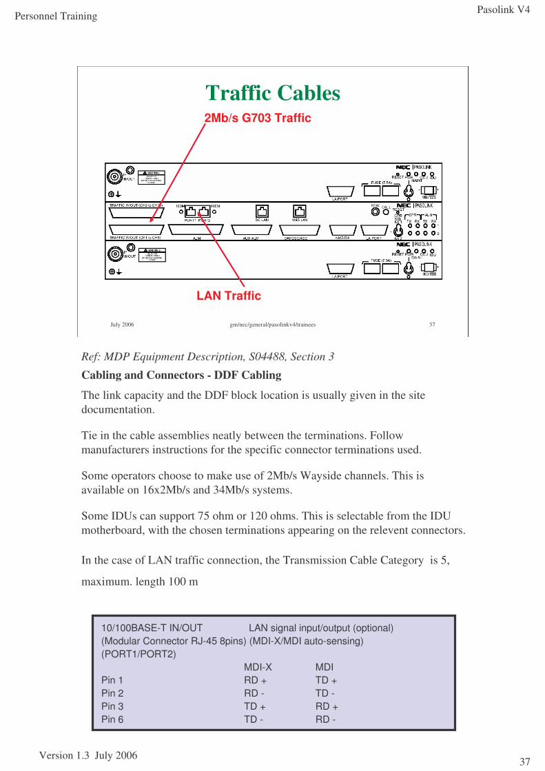
Traffic Cables
LAN Traffic
2Mb/s G703 Traffic
Ref: MDP Equipment Description, S04488, Section 3
Cabling and Connectors - DDF Cabling
The link capacity and the DDF block location is usually given in the site documentation.
Tie in the cable assemblies neatly between the terminations. Follow manufacturers instructions for the specific connector terminations used.
Some operators choose to make use of 2Mb/s Wayside channels. This is available on 16x2Mb/s and 34Mb/s systems.
Some IDUs can support 75 ohm or 120 ohms. This is selectable from the IDUmotherboard, with the chosen terminations appearing on the relevent connectors.
In the case of LAN traffic connection, the Transmission Cable Category is 5,
maximum. length 100 m
10/100BASE-T IN/OUT LAN signal input/output (optional)(Modular Connector RJ-45 8pins) (MDI-X/MDI auto-sensing)(PORT1/PORT2)
MDI-X MDIPin 1 RD + TD +Pin 2 RD - TD -Pin 3 TD + RD +Pin 6 TD - RD -
Pasolink V4
Version 1.3 July 2006
Personnel Training
38
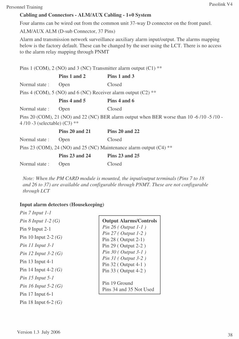
Cabling and Connectors - ALM/AUX Cabling - 1+0 SystemFour alarms can be wired out from the common unit 37-way D connector on the front panel.
ALM/AUX ALM (D-sub Connector, 37 Pins)
Alarm and transmission network surveillance auxiliary alarm input/output. The alarms mapping below is the factory default. These can be changed by the user using the LCT. There is no access to the alarm relay mapping through PNMT
Pins 1 (COM), 2 (NO) and 3 (NC) Transmitter alarm output (C1) **
Pins 1 and 2 Pins 1 and 3Normal state : Open Closed
Pins 4 (COM), 5 (NO) and 6 (NC) Receiver alarm output (C2) **
Pins 4 and 5 Pins 4 and 6Normal state : Open Closed
Pins 20 (COM), 21 (NO) and 22 (NC) BER alarm output when BER worse than 10 -6 /10 -5 /10 -4 /10 -3 (selectable) (C3) **
Pins 20 and 21 Pins 20 and 22Normal state : Open Closed
Pins 23 (COM), 24 (NO) and 25 (NC) Maintenance alarm output (C4) **
Pins 23 and 24 Pins 23 and 25Normal state : Open Closed
Input alarm detectors (Housekeeping)Pin 7 Input 1-1
Pin 8 Input 1-2 (G)
Pin 9 Input 2-1
Pin 10 Input 2-2 (G)
Pin 11 Input 3-1
Pin 12 Input 3-2 (G)
Pin 13 Input 4-1
Pin 14 Input 4-2 (G)
Pin 15 Input 5-1
Pin 16 Input 5-2 (G)
Pin 17 Input 6-1
Pin 18 Input 6-2 (G)
Output Alarms/ControlsPin 26 ( Output 1-1 )Pin 27 ( Output 1-2 )Pin 28 ( Output 2-1)Pin 29 ( Output 2-2 )Pin 30 ( Output 3-1 )Pin 31 ( Output 3-2 )Pin 32 ( Output 4-1 )Pin 33 ( Output 4-2 )
Pin 19 GroundPins 34 and 35 Not Used
Note: When the PM CARD module is mounted, the input/output terminals (Pins 7 to 18 and 26 to 37) are available and configurable through PNMT. These are not configurable through LCT
Pasolink V4
Version 1.3 July 2006
Personnel Training
39
July 2006 gm/nec/general/pasolinkv4/trainees 39
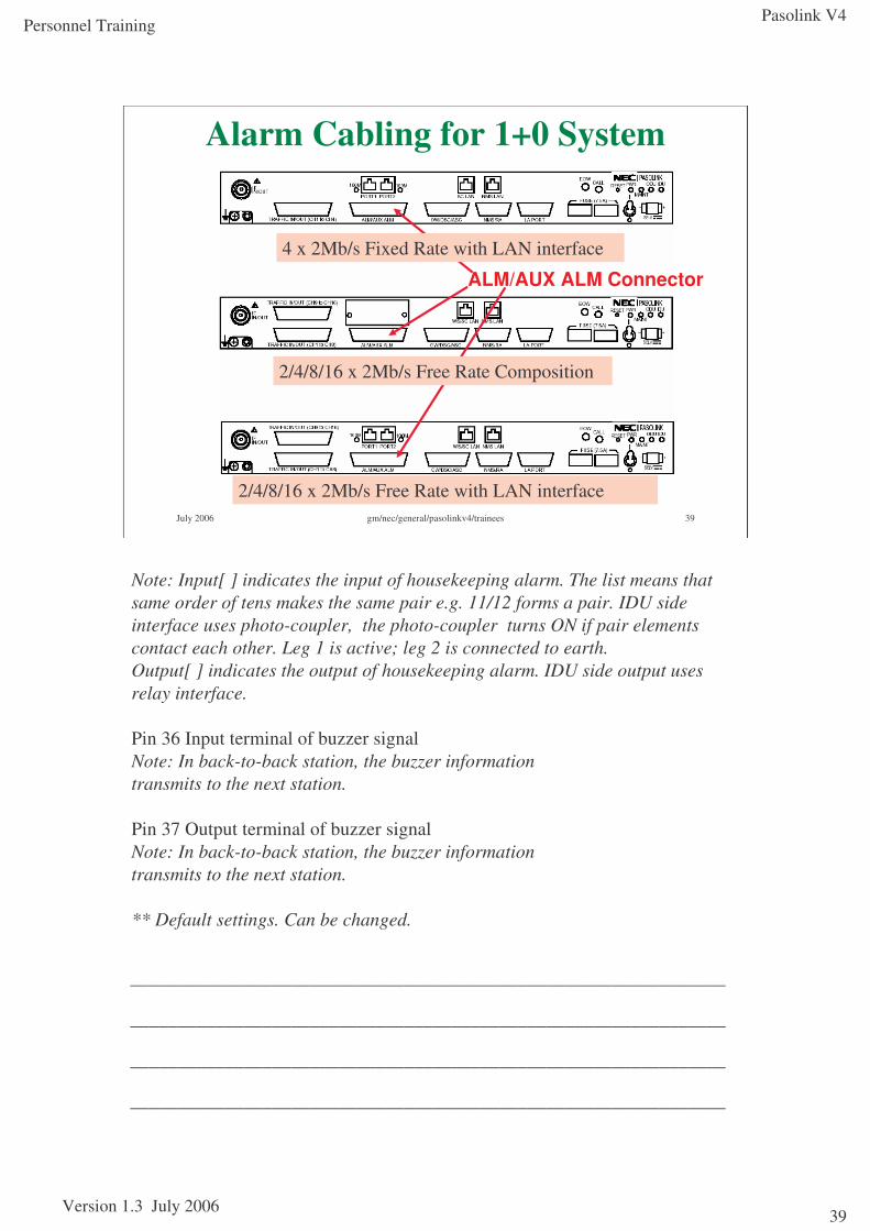
Alarm Cabling for 1+0 System
ALM/AUX ALM Connector
2/4/8/16 x 2Mb/s Free Rate Composition
2/4/8/16 x 2Mb/s Free Rate with LAN interface
4 x 2Mb/s Fixed Rate with LAN interface
Note: Input[ ] indicates the input of housekeeping alarm. The list means that same order of tens makes the same pair e.g. 11/12 forms a pair. IDU side interface uses photo-coupler, the photo-coupler turns ON if pair elements contact each other. Leg 1 is active; leg 2 is connected to earth.Output[ ] indicates the output of housekeeping alarm. IDU side output uses relay interface.
Pin 36 Input terminal of buzzer signalNote: In back-to-back station, the buzzer informationtransmits to the next station.
Pin 37 Output terminal of buzzer signalNote: In back-to-back station, the buzzer informationtransmits to the next station.
** Default settings. Can be changed.
_______________________________________________________________
_______________________________________________________________
_______________________________________________________________
_______________________________________________________________
Pasolink V4
Version 1.3 July 2006
Personnel Training
40
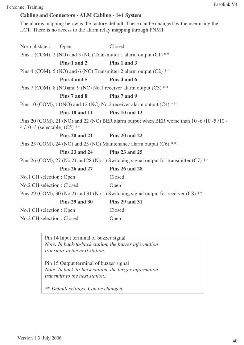
Cabling and Connectors - ALM Cabling - 1+1 SystemThe alarms mapping below is the factory default. These can be changed by the user using the LCT. There is no access to the alarm relay mapping through PNMT
Normal state : Open Closed
Pins 1 (COM), 2 (NO) and 3 (NC) Transmitter 1 alarm output (C1) **
Pins 1 and 2 Pins 1 and 3Pins 4 (COM), 5 (NO) and 6 (NC) Transmitter 2 alarm output (C2) **
Pins 4 and 5 Pins 4 and 6Pins 7 (COM), 8 (NO)and 9 (NC) No.1 receiver alarm output (C3) **
Pins 7 and 8 Pins 7 and 9Pins 10 (COM), 11(NO) and 12 (NC) No.2 receiver alarm output (C4) **
Pins 10 and 11 Pins 10 and 12Pins 20 (COM), 21 (NO) and 22 (NC) BER alarm output when BER worse than 10 -6 /10 -5 /10 -4 /10 -3 (selectable) (C5) **
Pins 20 and 21 Pins 20 and 22Pins 23 (COM), 24 (NO) and 25 (NC) Maintenance alarm output (C6) **
Pins 23 and 24 Pins 23 and 25Pins 26 (COM), 27 (No.2) and 28 (No.1) Switching signal output for transmitter (C7) **
Pins 26 and 27 Pins 26 and 28No.1 CH selection : Open Closed
No.2 CH selection : Closed Open
Pins 29 (COM), 30 (No.2) and 31 (No.1) Switching signal output for receiver (C8) **
Pins 29 and 30 Pins 29 and 31No.1 CH selection : Open Closed
No.2 CH selection : Closed Open
Pin 14 Input terminal of buzzer signalNote: In back-to-back station, the buzzer informationtransmits to the next station.
Pin 15 Output terminal of buzzer signalNote: In back-to-back station, the buzzer informationtransmits to the next station.
** Default settings. Can be changed.
Pasolink V4
Version 1.3 July 2006
Personnel Training
41
July 2006 gm/nec/general/pasolinkv4/trainees 41
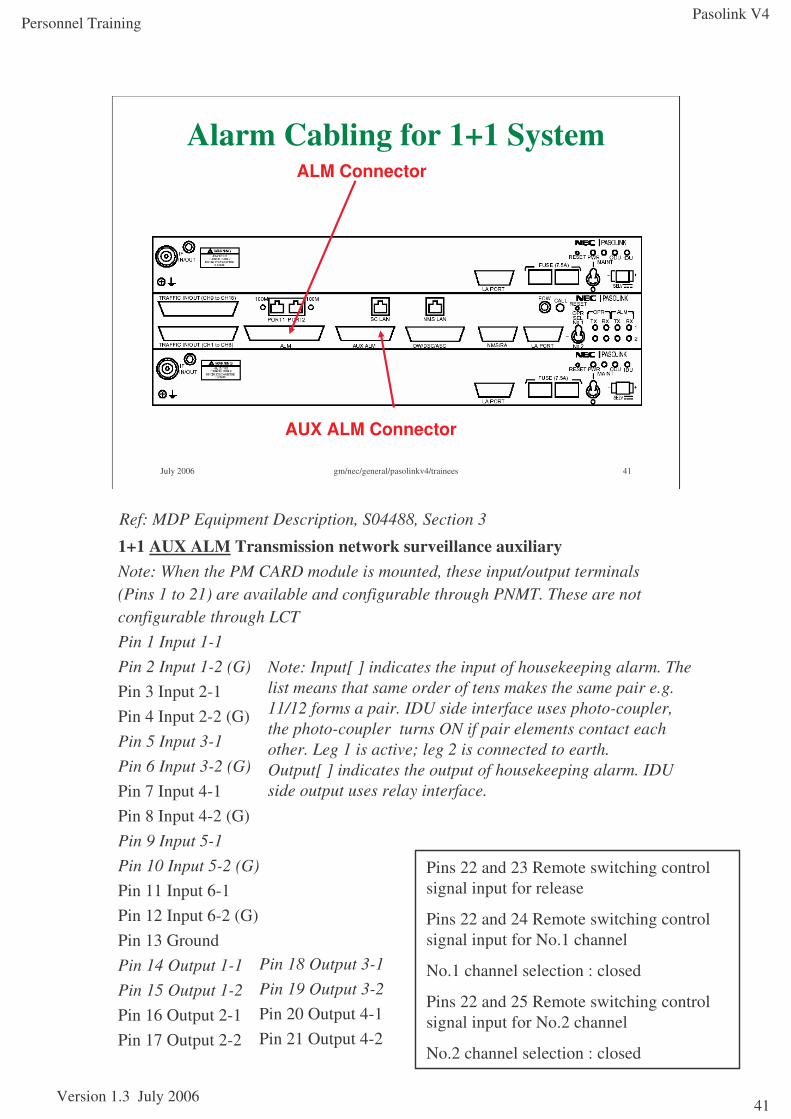
Alarm Cabling for 1+1 System
AUX ALM Connector
ALM Connector
1+1 AUX ALM Transmission network surveillance auxiliaryNote: When the PM CARD module is mounted, these input/output terminals (Pins 1 to 21) are available and configurable through PNMT. These are not configurable through LCTPin 1 Input 1-1Pin 2 Input 1-2 (G)Pin 3 Input 2-1Pin 4 Input 2-2 (G)Pin 5 Input 3-1Pin 6 Input 3-2 (G)Pin 7 Input 4-1Pin 8 Input 4-2 (G)Pin 9 Input 5-1Pin 10 Input 5-2 (G)Pin 11 Input 6-1Pin 12 Input 6-2 (G)Pin 13 GroundPin 14 Output 1-1Pin 15 Output 1-2Pin 16 Output 2-1Pin 17 Output 2-2
Note: Input[ ] indicates the input of housekeeping alarm. The list means that same order of tens makes the same pair e.g. 11/12 forms a pair. IDU side interface uses photo-coupler, the photo-coupler turns ON if pair elements contact each other. Leg 1 is active; leg 2 is connected to earth.Output[ ] indicates the output of housekeeping alarm. IDU side output uses relay interface.
Pin 18 Output 3-1Pin 19 Output 3-2Pin 20 Output 4-1Pin 21 Output 4-2
Pins 22 and 23 Remote switching control signal input for release
Pins 22 and 24 Remote switching control signal input for No.1 channel
No.1 channel selection : closed
Pins 22 and 25 Remote switching control signal input for No.2 channel
No.2 channel selection : closed
Ref: MDP Equipment Description, S04488, Section 3
Pasolink V4
Version 1.3 July 2006
Personnel Training
42
July 2006 gm/nec/general/pasolinkv4/trainees 42
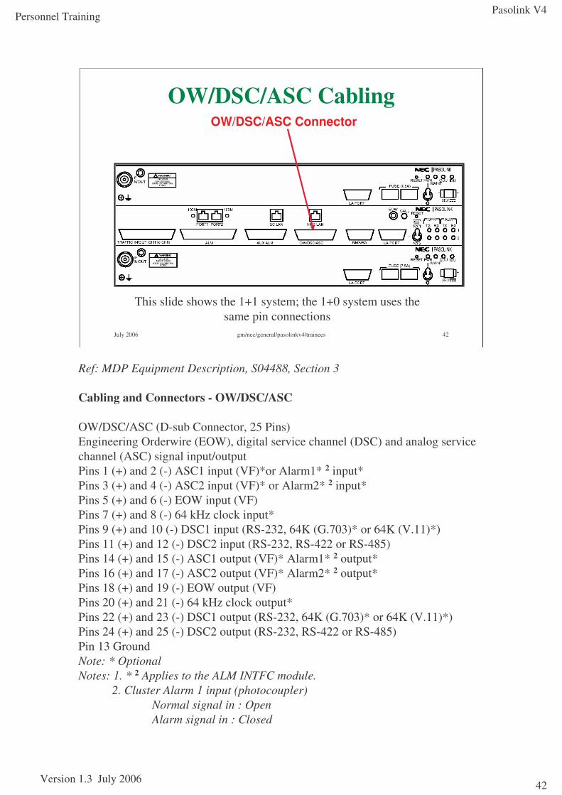
OW/DSC/ASC CablingOW/DSC/ASC Connector
This slide shows the 1+1 system; the 1+0 system uses the same pin connections
Ref: MDP Equipment Description, S04488, Section 3
Cabling and Connectors - OW/DSC/ASC
OW/DSC/ASC (D-sub Connector, 25 Pins)Engineering Orderwire (EOW), digital service channel (DSC) and analog service channel (ASC) signal input/outputPins 1 (+) and 2 (-) ASC1 input (VF)*or Alarm1* 2 input*Pins 3 (+) and 4 (-) ASC2 input (VF)* or Alarm2* 2 input*Pins 5 (+) and 6 (-) EOW input (VF)Pins 7 (+) and 8 (-) 64 kHz clock input*Pins 9 (+) and 10 (-) DSC1 input (RS-232, 64K (G.703)* or 64K (V.11)*)Pins 11 (+) and 12 (-) DSC2 input (RS-232, RS-422 or RS-485)Pins 14 (+) and 15 (-) ASC1 output (VF)* Alarm1* 2 output*Pins 16 (+) and 17 (-) ASC2 output (VF)* Alarm2* 2 output*Pins 18 (+) and 19 (-) EOW output (VF)Pins 20 (+) and 21 (-) 64 kHz clock output*Pins 22 (+) and 23 (-) DSC1 output (RS-232, 64K (G.703)* or 64K (V.11)*)Pins 24 (+) and 25 (-) DSC2 output (RS-232, RS-422 or RS-485)Pin 13 GroundNote: * OptionalNotes: 1. * 2 Applies to the ALM INTFC module.
2. Cluster Alarm 1 input (photocoupler)Normal signal in : OpenAlarm signal in : Closed
Pasolink V4
Version 1.3 July 2006
Personnel Training
43
July 2006 gm/nec/general/pasolinkv4/trainees 43
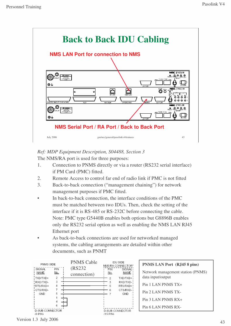
Back to Back IDU Cabling
NMS Serial Port / RA Port / Back to Back Port
NMS LAN Port for connection to NMS
Ref: MDP Equipment Description, S04488, Section 3The NMS/RA port is used for three purposes:1. Connection to PNMS directly or via a router (RS232 serial interface)
if PM Card (PMC) fitted.2. Remote Access to control far end of radio link if PMC is not fitted3. Back-to-back connection (“management chaining”) for network
management purposes if PMC fitted.• In back-to-back connection, the interface conditions of the PMC
must be matched between two IDUs. Then, check the setting of the interface if it is RS-485 or RS-232C before connecting the cable. Note: PMC type G5440B enables both options but G8896B enables only the RS232 serial option as well as enabling the NMS LAN RJ45 Ethernet port
• As back-to-back connections are used for networked managed systems, the cabling arrangements are detailed within other documents, such as PNMT
PNMS Cable (RS232 connection)
PNMS LAN Port (RJ45 8 pins)
Network management station (PNMS) data input/output
Pin 1 LAN PNMS TX+
Pin 2 LAN PNMS TX-
Pin 3 LAN PNMS RX+
Pin 6 LAN PNMS RX-
Pasolink V4
Version 1.3 July 2006
Personnel Training
44
July 2006 gm/nec/general/pasolinkv4/trainees 44
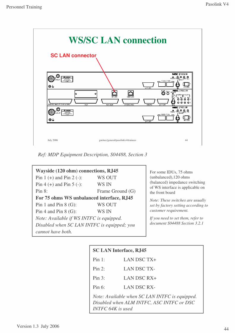
WS/SC LAN connectionSC LAN connector
Ref: MDP Equipment Description, S04488, Section 3
Wayside (120 ohm) connections, RJ45Pin 1 (+) and Pin 2 (-): WS OUTPin 4 (+) and Pin 5 (-): WS INPin 8: Frame Ground (G)For 75 ohms WS unbalanced interface, RJ45Pin 1 and Pin 8 (G): WS OUTPin 4 and Pin 8 (G): WS INNote: Available if WS INTFC is equipped.Disabled when SC LAN INTFC is equipped; you cannot have both.
SC LAN Interface, RJ45
Pin 1: LAN DSC TX+
Pin 2: LAN DSC TX-
Pin 3: LAN DSC RX+
Pin 6: LAN DSC RX-
Note: Available when SC LAN INTFC is equipped. Disabled when ALM INTFC, ASC INTFC or DSC INTFC 64K is used
For some IDUs, 75 ohms (unbalanced),120 ohms (balanced) impedance switching of WS interface is applicable on the front board
Note: These switches are usually set by factory setting according to customer requirement.
If you need to set them, refer to document S04488 Section 3.2.1
Pasolink V4
Version 1.3 July 2006
Personnel Training
45
July 2006 gm/nec/general/pasolinkv4/trainees 45
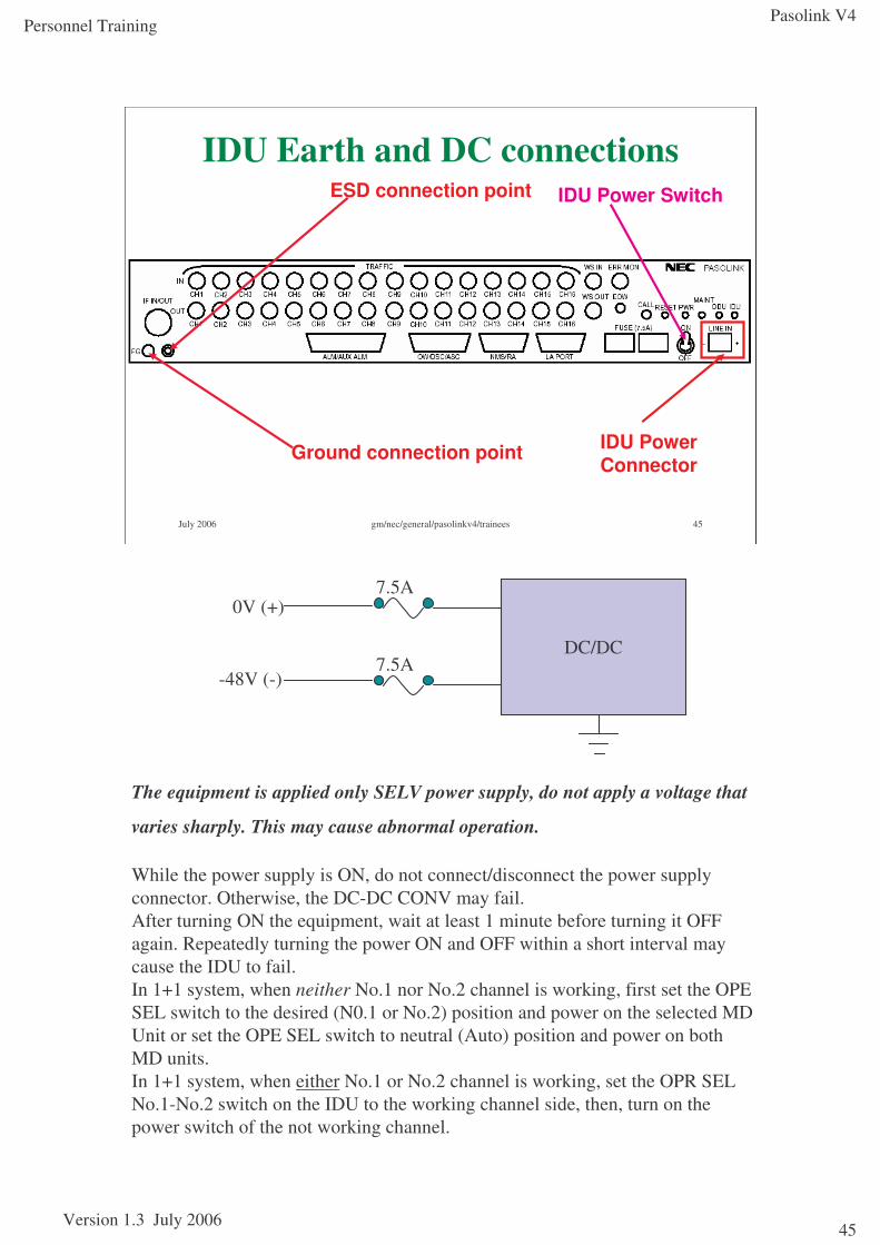
IDU Earth and DC connections
Ground connection point
ESD connection point IDU Power Switch
IDU Power Connector
The equipment is applied only SELV power supply, do not apply a voltage that
varies sharply. This may cause abnormal operation.
While the power supply is ON, do not connect/disconnect the power supply connector. Otherwise, the DC-DC CONV may fail.After turning ON the equipment, wait at least 1 minute before turning it OFF again. Repeatedly turning the power ON and OFF within a short interval may cause the IDU to fail.In 1+1 system, when neither No.1 nor No.2 channel is working, first set the OPE SEL switch to the desired (N0.1 or No.2) position and power on the selected MD Unit or set the OPE SEL switch to neutral (Auto) position and power on both MD units.In 1+1 system, when either No.1 or No.2 channel is working, set the OPR SEL No.1-No.2 switch on the IDU to the working channel side, then, turn on the power switch of the not working channel.
DC/DC
0V (+)
-48V (-)
7.5A
7.5A
Pasolink V4
Version 1.3 July 2006
Personnel Training
46
July 2006 gm/nec/general/pasolinkv4/trainees 46
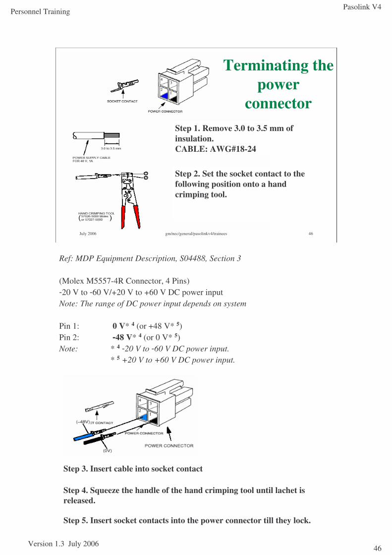
Terminating the power
connectorStep 1. Remove 3.0 to 3.5 mm of insulation. CABLE: AWG#18-24
Step 2. Set the socket contact to thefollowing position onto a handcrimping tool.
Ref: MDP Equipment Description, S04488, Section 3
(Molex M5557-4R Connector, 4 Pins)-20 V to -60 V/+20 V to +60 V DC power inputNote: The range of DC power input depends on system
Pin 1: 0 V* 4 (or +48 V* 5)Pin 2: -48 V* 4 (or 0 V* 5)Note: * 4 -20 V to -60 V DC power input.
* 5 +20 V to +60 V DC power input.
Step 3. Insert cable into socket contact
Step 4. Squeeze the handle of the hand crimping tool until lachet is released.
Step 5. Insert socket contacts into the power connector till they lock.
Pasolink V4
Version 1.3 July 2006
Personnel Training
47
Cabling and Connectors - IF Cable
A single coaxial cable links an ODU to a channel unit.
For cable lengths up to 90m, RG223/U is typically used, with appropriate 'N' type connectors provided by the installer.
For cable lengths greater than 90m, Belden 9913 is typically used, with appropriate 'N' type connectors provided by the installer.
Prior to installation and with the ODU end terminated, check the cable for continuity of the screen and centre conductor. Check for short circuit between screen and centre conductor.
Ensure that a service/drip-loop of about 1 metre is allowed for at the antenna end for maintenance or relocation purposes. The excess cabling must be secured to the pole.
Route and secure the cable using either black UV resistant tie-wraps or studding and REM straps or equivalent approved if agreed with a third-party site owner.
Where the cable is continuously supported by the cable tray in horizontal and vertical runs, tie in securely at maximum intervals of 1000mm. Where the cable is run on cable racking or its weight is not supported at all e.g. on walls or trays fixed vertically to walls, tie in or fix at maximum intervals of 500mm.
Where there is insufficient space on the trays or racking, or they have not been provided, it is permissible to fix the cables to the pole or direct to a tower leg, but not to LDF Heliax feeder cables or AC power cabling.
NOTE: Care should be taken to ensure that the coaxial cable is not damaged by strapping too tightly or strapping against sharp edges.
Note:Tighten connectors to 196 Ncm torque. In case of employing hitless 1+1 protection, ensure the length of the two IF cables are the same (within 50m difference)
Danger: Do not disconnect the coaxial cable before turning off the power switch on the IDU. Do not touch the IF cable jack core before turning off the power switch.
Pasolink V4
Version 1.3 July 2006
Personnel Training
48
July 2006 gm/nec/general/pasolinkv4/trainees 48
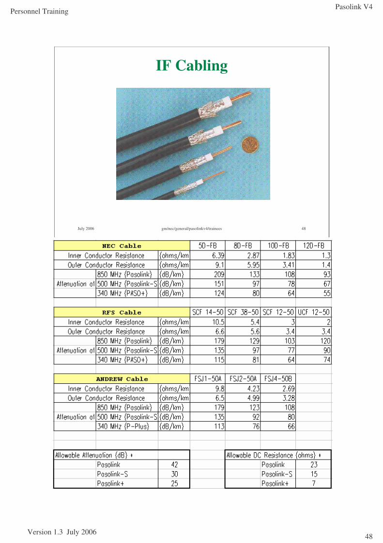
IF Cabling
Pasolink V4
Version 1.3 July 2006
Personnel Training
49
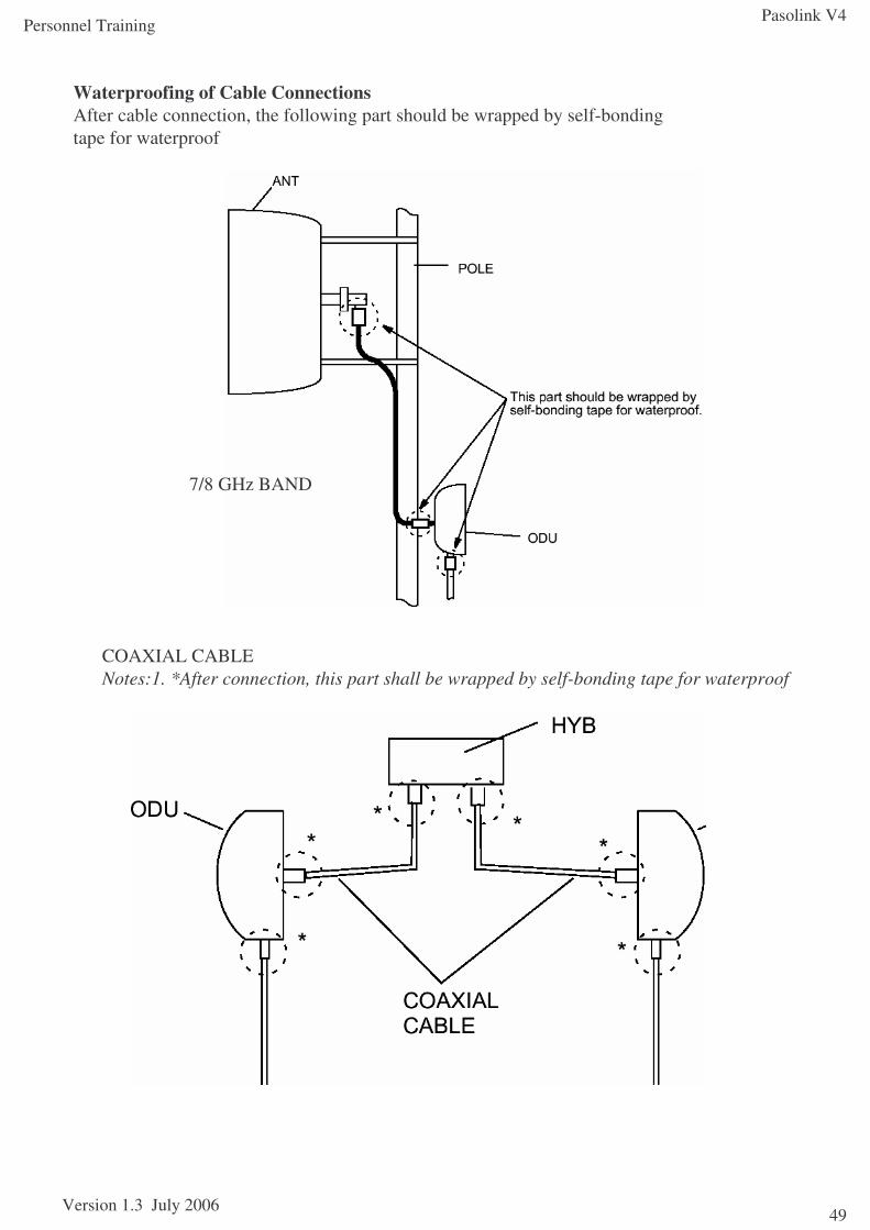
Waterproofing of Cable ConnectionsAfter cable connection, the following part should be wrapped by self-bondingtape for waterproof
7/8 GHz BAND
COAXIAL CABLENotes:1. *After connection, this part shall be wrapped by self-bonding tape for waterproof
Pasolink V4
Version 1.3 July 2006
Personnel Training
50
July 2006 gm/nec/general/pasolinkv4/trainees 50
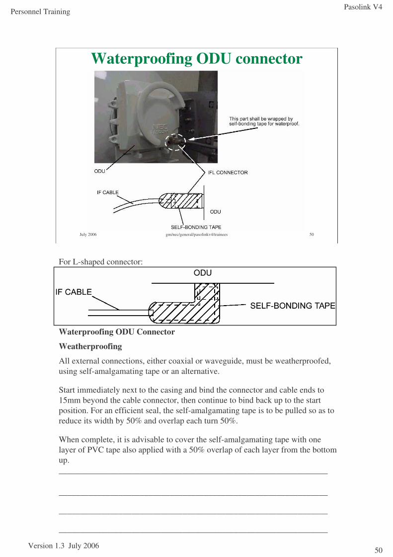
Waterproofing ODU connector
For L-shaped connector:
_______________________________________________________________
Waterproofing ODU Connector
Weatherproofing
All external connections, either coaxial or waveguide, must be weatherproofed, using self-amalgamating tape or an alternative.
Start immediately next to the casing and bind the connector and cable ends to 15mm beyond the cable connector, then continue to bind back up to the start position. For an efficient seal, the self-amalgamating tape is to be pulled so as to reduce its width by 50% and overlap each turn 50%.
When complete, it is advisable to cover the self-amalgamating tape with one layer of PVC tape also applied with a 50% overlap of each layer from the bottom up. _______________________________________________________________
_______________________________________________________________
_______________________________________________________________
_______________________________________________________________
Pasolink V4
Version 1.3 July 2006
Personnel Training
51
July 2006 gm/nec/general/pasolinkv4/trainees 51
Module 3Commissioning using LCT
ObjectivesAt the end of this module, you will be able to do the following:
•State the specialist tools that are required to commission the Pasolink V4 equipment
•Describe the use of the local management terminal required to configure the Pasolink V4 equipment
•Demonstrate how to use the management terminal to complete the initial line up
•Describe how to align the Pasolink V4 link and to confirm that the target RSL matches the predicted value
•Describe how to set a 1+0 link into a 1+1 link and vice versa
References:Pasolink V4 User (Instruction) Manual ROI-S0xxxx-051E
Abbreviations ROI-S04491-052EGeneral System Description ROI-S04604-052EMeasurement Procedure ROI-S04607-054ETRP Equipment Description ROI-S04605-054ERadio Frequency Assignment (n GHz) ROI-various-05xE
MDP Equipment Description ROI-S04488-058EInstallation and Initial Lineup ROI-S04606-054E
Pasolink V4 Sub-band Change ProcedurePasolink V4 MTD (1+0 / 1+1) PL035-01
Pasolink V4
Version 1.3 July 2006
Personnel Training
52
HyperTerminal Configuration (for LCT)Configure a HyperTerminal session as follows:
Select Start-Programs-Accessories-HyperTerminal-HyperTerminal.
Name the session ‘Pasolink P’.
Select Connection as ‘COM1’. Click on [Okay].
In the next screen set the following values:
•Baud rate : 9600
•Data Length : 8
•Parity Check : none
•Stop bit : 2
•Flow control: Hardware
Click on [Okay].
Select File-Properties, and click on the ‘Settings’ tab. Set the following value:
Emulation : VT100 Video Terminal
Click on [ASCII Config]
Set the following values:
ASCII Sending Send line end with line feeds
ASCII Receiving Wrap lines that exceed terminal width
Click on [Okay], and again.
Re-save the session.
When Windows NT4.0 and HyperTerminal is used, “Program Download” function is not available. In this case, please use other terminal software. (e.g., TeraTerm Pro 2.3: http://hp.vector.co.jp/authors/VA002416/teraterm.html)
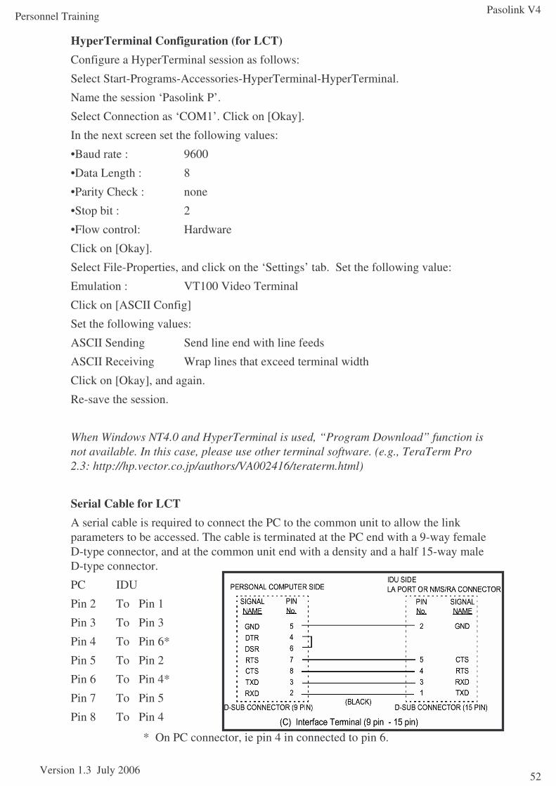
Serial Cable for LCTA serial cable is required to connect the PC to the common unit to allow the link parameters to be accessed. The cable is terminated at the PC end with a 9-way female D-type connector, and at the common unit end with a density and a half 15-way male D-type connector.
PC IDU
Pin 2 To Pin 1
Pin 3 To Pin 3
Pin 4 To Pin 6*
Pin 5 To Pin 2
Pin 6 To Pin 4*
Pin 7 To Pin 5
Pin 8 To Pin 4
* On PC connector, ie pin 4 in connected to pin 6.
Pasolink V4
Version 1.3 July 2006
Personnel Training
53
July 2006 gm/nec/general/pasolinkv4/trainees 53
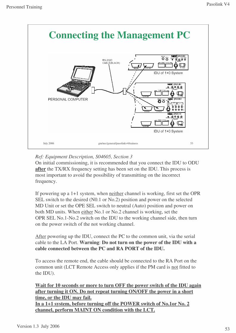
Connecting the Management PC
Ref: Equipment Description, S04605, Section 3On initial commissioning, it is recommended that you connect the IDU to ODU after the TX/RX frequency setting has been set on the IDU. This process is most important to avoid the possibility of transmitting on the incorrect frequency.
If powering up a 1+1 system, when neither channel is working, first set the OPR SEL switch to the desired (N0.1 or No.2) position and power on the selected MD Unit or set the OPE SEL switch to neutral (Auto) position and power on both MD units. When either No.1 or No.2 channel is working, set theOPR SEL No.1-No.2 switch on the IDU to the working channel side, then turn on the power switch of the not working channel.
After powering up the IDU, connect the PC to the common unit, via the serial cable to the LA Port. Warning: Do not turn on the power of the IDU with a cable connected between the PC and RA PORT of the IDU.
To access the remote end, the cable should be connected to the RA Port on the common unit (LCT Remote Access only applies if the PM card is not fitted to the IDU).
Wait for 10 seconds or more to turn OFF the power switch of the IDU again after turning it ON. Do not repeat turning ON/OFF the power in a short time, or the IDU may fail.In a 1+1 system, before turning off the POWER switch of No.1or No. 2 channel, perform MAINT ON condition with the LCT.
Pasolink V4
Version 1.3 July 2006
Personnel Training
54
Link commissioning – Logging in
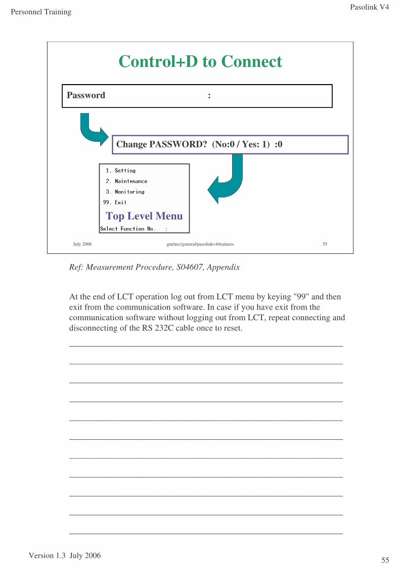
Terminal Set-UpStart ‘Pasolink P’ HyperTerminal session.
Once the window is open, press [CNTRL-D].
At ‘Password’ prompt, press [Return].
At ‘Change Password’ prompt, enter [0][Return].
The following options will be displayed:
•Setting
•Maintenance
•Monitoring
•Exit
Caution: If login is not possible, check if settings of the communication format are ok.
Note:•The keys, “0” to “9” are used for selection of the menu or entering values. “RETURN”key is used for confirmation of entering values. “ESC” key is used for cancellation of entering values and display the high rank menu.
•When controlling the station, connect the cable to the LA PORT. When controlling the opposite station, connect the cable to the NMS/RA.
•In the following cases, the NMS/ RA cannot be used:
• The PM CARD is mounted on the IDU.
• H BER alarm is issued.
•When the PC is connected to the NMS/RA terminal to control the opposite station, enter password for that station (if required)
Pasolink V4
Version 1.3 July 2006
Personnel Training
55
July 2006 gm/nec/general/pasolinkv4/trainees 55
Control+D to Connect
Password :
Change PASSWORD? (No:0 / Yes: 1) :0
Top Level Menu
Ref: Measurement Procedure, S04607, Appendix
At the end of LCT operation log out from LCT menu by keying "99" and then exit from the communication software. In case if you have exit from the communication software without logging out from LCT, repeat connecting and disconnecting of the RS 232C cable once to reset.
_______________________________________________________________
_______________________________________________________________
_______________________________________________________________
_______________________________________________________________
_______________________________________________________________
_______________________________________________________________
_______________________________________________________________
_______________________________________________________________
_______________________________________________________________
_______________________________________________________________
_______________________________________________________________
Pasolink V4
Version 1.3 July 2006
Personnel Training
56
Link commissioning - Main Configuration
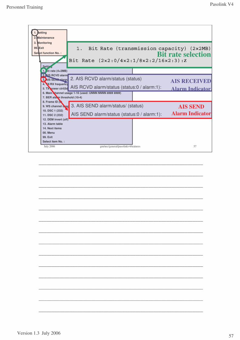
1. Bit Rate
Enter [1] [Return].
Select the required bit rate. Enter [2][Return] for 8x2, and [3][Return] for 16x2.
Caution: In the fixed bit rate type, do not change this item. If you change this item, service is impossible. Press the “0” “1” “2” or “3” key and “RETURN” key,
Caution: Set the same bit rate to the opposite station to enable service.Note: In the bit rate free type, setting to “4” or “5” is impossible, because the bit rate free type is not applied to 8 MB × 1 and 34 MB × 1 system.
2. AIS RCVD on/off (off) [‘off’ denotes alarms are inhibited, but status will still be shown; ‘on’ denotes alarms are not inhibited]
This specifies whether IDU generates an alarm if it detects AIS at the 2Mb/s input. The AIS RCVD is used to select whether or not a MAJOR IDU alarm is generated when AIS is received from any of the channels.
Enter [2][Return], then choose AIS RCVD on/off (off:0 / on:1) :
Usually set to disabled (off), thereby disabling this alarm function for all tributaries – status will still be displayed. Specific channels can be enabled from the ‘Hidden Menu’.
3. AIS SEND on/off (off) [‘off’ denotes alarms are inhibited, but status will still be shown; ‘on’ denotes alarms are not inhibited]
This option is used to select whether or not a MAJOR IDU alarm is generated when AIS is sent from any of the E1 tribs
Enter [3][Return], then choose AIS SEND on/off (off:0 / on:1) :
Usually set to disabled (off), thereby disabling this alarm function for all channels. Status will still be displayed.
Pasolink V4
Version 1.3 July 2006
Personnel Training
57
July 2006 gm/nec/general/pasolinkv4/trainees 57
1. Setting
2. Maintenance
3. Monitoring
99. Exit
Select function No. :
Setting1. Bit rate (4×2MB)2. AIS RCVD alarm/status (status)3. AIS SEND alarm/status (status)4. TX/RX frequency (5ch)5. TX power ctrl(0dB)6. Main channel usage 1-16 (used: UNNN NNNN #### ####)
7. BER alarm threshold (10-4)8. Frame ID (0)9. WS channel usage (not used)10. DSC 1 (232)11. DSC 2 (232)12. DEM invert (off)13. Alarm table14. Next items00. Menu99. ExitSelect item No. :
Bit rate selection
2. AIS RCVD alarm/status (status)
AIS RCVD alarm/status (status:0 / alarm:1):AIS RECEIVED Alarm Indicator
3. AIS SEND alarm/status/ (status)
AIS SEND alarm/status (status:0 / alarm:1):
AIS SEND Alarm Indicator
_______________________________________________________________
_______________________________________________________________
_______________________________________________________________
_______________________________________________________________
_______________________________________________________________
_______________________________________________________________
_______________________________________________________________
_______________________________________________________________
_______________________________________________________________
_______________________________________________________________
_______________________________________________________________
_______________________________________________________________
_______________________________________________________________
_______________________________________________________________
Pasolink V4
Version 1.3 July 2006
Personnel Training
58
Link commissioning - Main Configuration
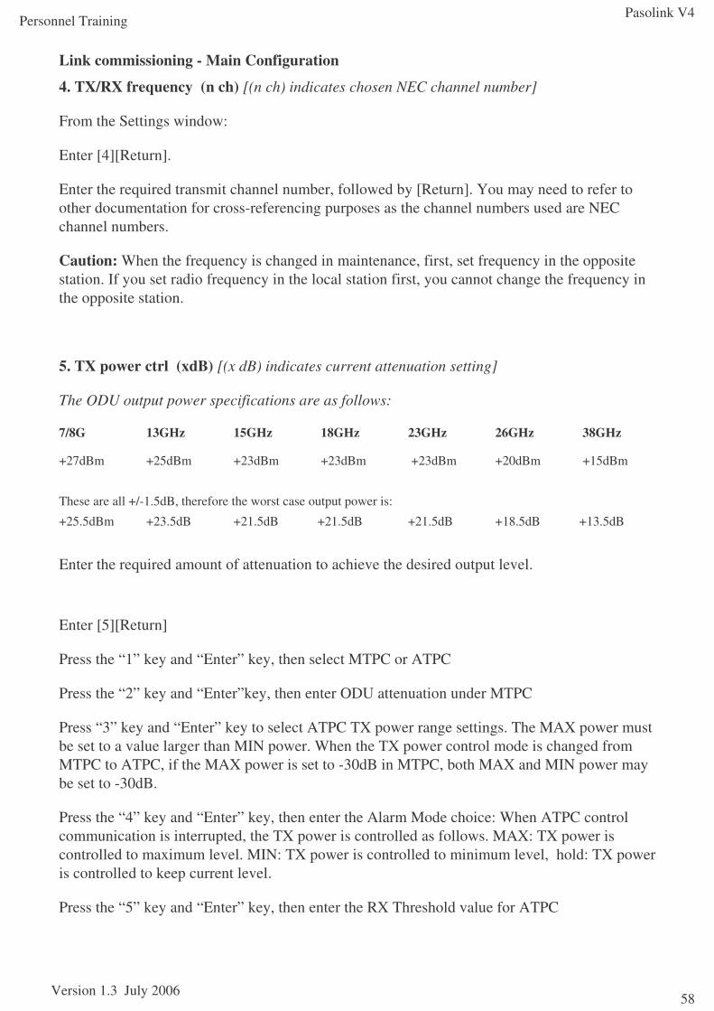
4. TX/RX frequency (n ch) [(n ch) indicates chosen NEC channel number]
From the Settings window:
Enter [4][Return].
Enter the required transmit channel number, followed by [Return]. You may need to refer to other documentation for cross-referencing purposes as the channel numbers used are NEC channel numbers.
Caution: When the frequency is changed in maintenance, first, set frequency in the opposite station. If you set radio frequency in the local station first, you cannot change the frequency in the opposite station.
5. TX power ctrl (xdB) [(x dB) indicates current attenuation setting]
The ODU output power specifications are as follows:
7/8G 13GHz 15GHz 18GHz 23GHz 26GHz 38GHz
+27dBm +25dBm +23dBm +23dBm +23dBm +20dBm +15dBm
These are all +/-1.5dB, therefore the worst case output power is:
+25.5dBm +23.5dB +21.5dB +21.5dB +21.5dB +18.5dB +13.5dB
Enter the required amount of attenuation to achieve the desired output level.
Enter [5][Return]
Press the “1” key and “Enter” key, then select MTPC or ATPC
Press the “2” key and “Enter”key, then enter ODU attenuation under MTPC
Press “3” key and “Enter” key to select ATPC TX power range settings. The MAX power must be set to a value larger than MIN power. When the TX power control mode is changed from MTPC to ATPC, if the MAX power is set to -30dB in MTPC, both MAX and MIN power may be set to -30dB.
Press the “4” key and “Enter” key, then enter the Alarm Mode choice: When ATPC control communication is interrupted, the TX power is controlled as follows. MAX: TX power is controlled to maximum level. MIN: TX power is controlled to minimum level, hold: TX power is controlled to keep current level.
Press the “5” key and “Enter” key, then enter the RX Threshold value for ATPC
Pasolink V4
Version 1.3 July 2006
Personnel Training
59
July 2006 gm/nec/general/pasolinkv4/trainees 59
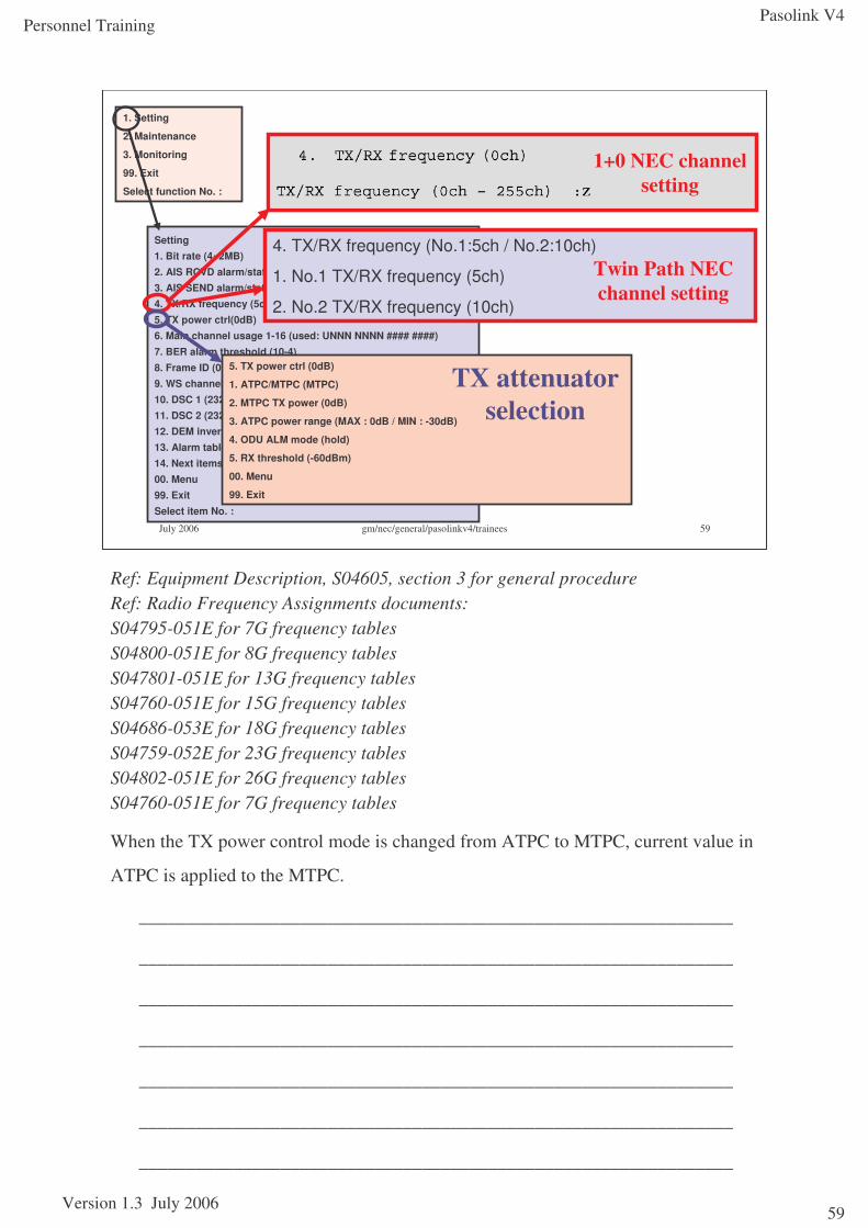
Setting1. Bit rate (4×2MB)2. AIS RCVD alarm/status (status)3. AIS SEND alarm/status (status)4. TX/RX frequency (5ch)5. TX power ctrl(0dB)6. Main channel usage 1-16 (used: UNNN NNNN #### ####)
7. BER alarm threshold (10-4)8. Frame ID (0)9. WS channel usage (not used)10. DSC 1 (232)11. DSC 2 (232)12. DEM invert (off)13. Alarm table14. Next items00. Menu99. ExitSelect item No. :
1. Setting
2. Maintenance
3. Monitoring
99. Exit
Select function No. :
1+0 NEC channel setting
5. TX power ctrl (0dB)
1. ATPC/MTPC (MTPC)
2. MTPC TX power (0dB)
3. ATPC power range (MAX : 0dB / MIN : -30dB)
4. ODU ALM mode (hold)
5. RX threshold (-60dBm)
00. Menu
99. Exit
TX attenuator selection
4. TX/RX frequency (No.1:5ch / No.2:10ch)
1. No.1 TX/RX frequency (5ch)
2. No.2 TX/RX frequency (10ch)
Twin Path NEC channel setting
Ref: Equipment Description, S04605, section 3 for general procedureRef: Radio Frequency Assignments documents:S04795-051E for 7G frequency tablesS04800-051E for 8G frequency tablesS047801-051E for 13G frequency tablesS04760-051E for 15G frequency tablesS04686-053E for 18G frequency tablesS04759-052E for 23G frequency tablesS04802-051E for 26G frequency tablesS04760-051E for 7G frequency tables
When the TX power control mode is changed from ATPC to MTPC, current value in
ATPC is applied to the MTPC.
_______________________________________________________________
_______________________________________________________________
_______________________________________________________________
_______________________________________________________________
_______________________________________________________________
_______________________________________________________________
_______________________________________________________________
Pasolink V4
Version 1.3 July 2006
Personnel Training
60
Link commissioning - Main Configuration continued
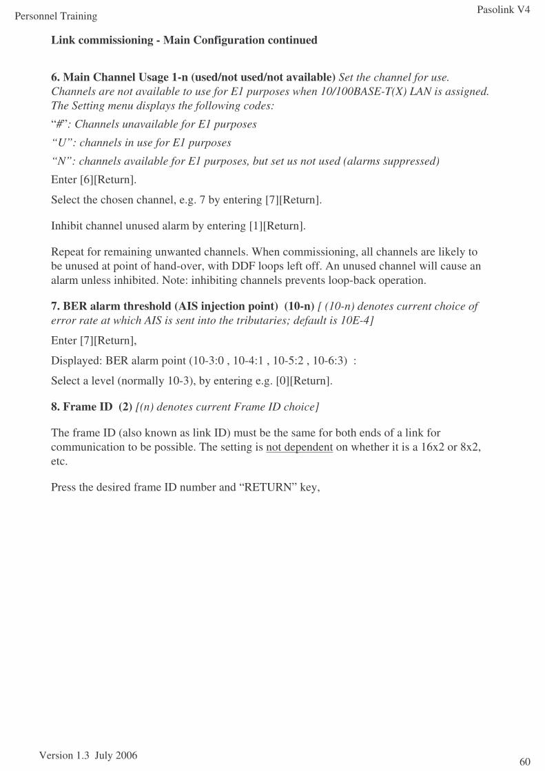
6. Main Channel Usage 1-n (used/not used/not available) Set the channel for use. Channels are not available to use for E1 purposes when 10/100BASE-T(X) LAN is assigned. The Setting menu displays the following codes:
“#”: Channels unavailable for E1 purposes
“U”: channels in use for E1 purposes
“N”: channels available for E1 purposes, but set us not used (alarms suppressed)
Enter [6][Return].
Select the chosen channel, e.g. 7 by entering [7][Return].
Inhibit channel unused alarm by entering [1][Return].
Repeat for remaining unwanted channels. When commissioning, all channels are likely to be unused at point of hand-over, with DDF loops left off. An unused channel will cause an alarm unless inhibited. Note: inhibiting channels prevents loop-back operation.
7. BER alarm threshold (AIS injection point) (10-n) [ (10-n) denotes current choice of error rate at which AIS is sent into the tributaries; default is 10E-4]
Enter [7][Return],
Displayed: BER alarm point (10-3:0 , 10-4:1 , 10-5:2 , 10-6:3) :
Select a level (normally 10-3), by entering e.g. [0][Return].
8. Frame ID (2) [(n) denotes current Frame ID choice]
The frame ID (also known as link ID) must be the same for both ends of a link for communication to be possible. The setting is not dependent on whether it is a 16x2 or 8x2, etc.
Press the desired frame ID number and “RETURN” key,
Pasolink V4
Version 1.3 July 2006
Personnel Training
61
July 2006 gm/nec/general/pasolinkv4/trainees 61
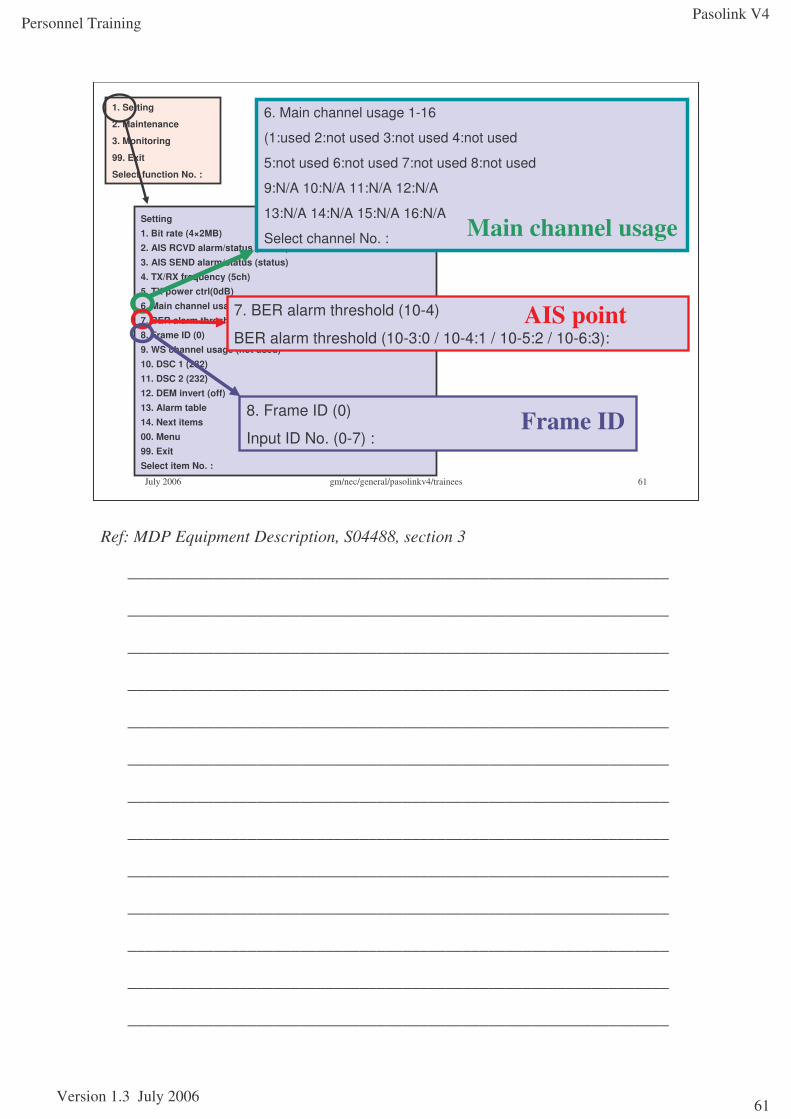
Setting1. Bit rate (4×2MB)2. AIS RCVD alarm/status (status)3. AIS SEND alarm/status (status)4. TX/RX frequency (5ch)5. TX power ctrl(0dB)6. Main channel usage 1-16 (used: UNNN NNNN #### ####)
7. BER alarm threshold (10-4)8. Frame ID (0)9. WS channel usage (not used)10. DSC 1 (232)11. DSC 2 (232)12. DEM invert (off)13. Alarm table14. Next items00. Menu99. ExitSelect item No. :
1. Setting
2. Maintenance
3. Monitoring
99. Exit
Select function No. :
6. Main channel usage 1-16
(1:used 2:not used 3:not used 4:not used
5:not used 6:not used 7:not used 8:not used
9:N/A 10:N/A 11:N/A 12:N/A
13:N/A 14:N/A 15:N/A 16:N/A
Select channel No. : Main channel usage
7. BER alarm threshold (10-4)
BER alarm threshold (10-3:0 / 10-4:1 / 10-5:2 / 10-6:3):AIS point
8. Frame ID (0)
Input ID No. (0-7) :Frame ID
Ref: MDP Equipment Description, S04488, section 3
_______________________________________________________________
_______________________________________________________________
_______________________________________________________________
_______________________________________________________________
_______________________________________________________________
_______________________________________________________________
_______________________________________________________________
_______________________________________________________________
_______________________________________________________________
_______________________________________________________________
_______________________________________________________________
_______________________________________________________________
_______________________________________________________________
Pasolink V4
Version 1.3 July 2006
Personnel Training
62
Link commissioning - Main Configuration continued
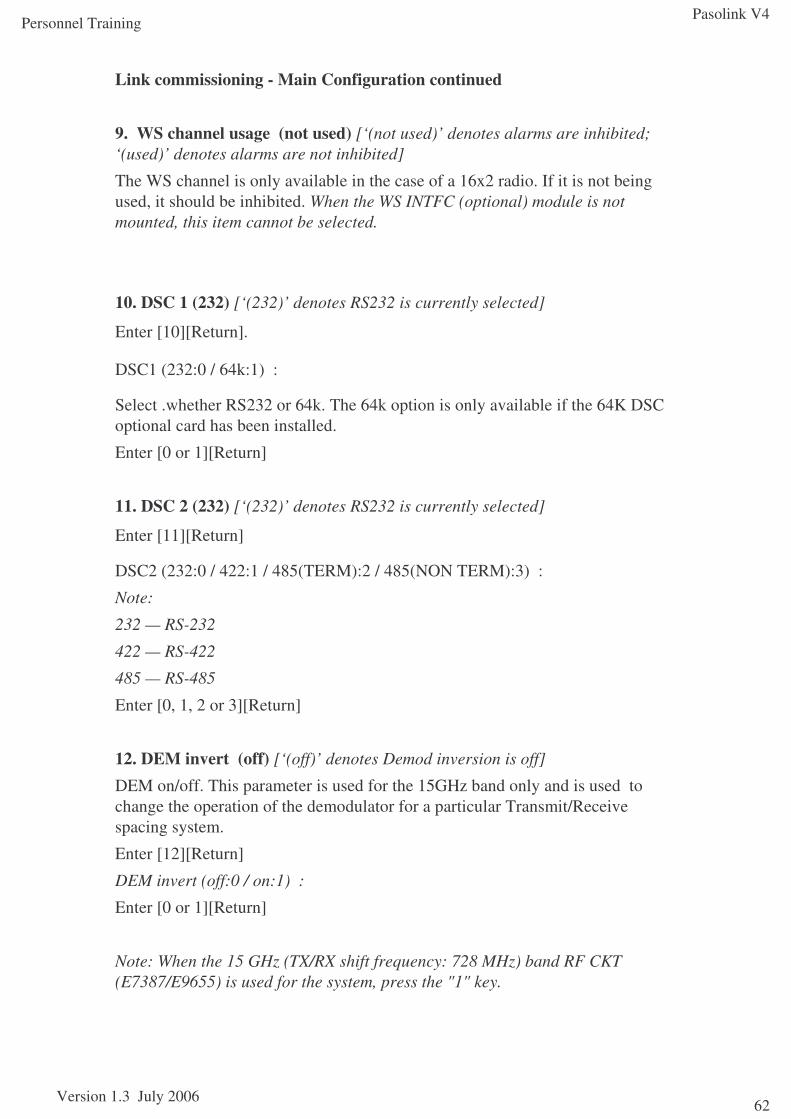
9. WS channel usage (not used) [‘(not used)’ denotes alarms are inhibited; ‘(used)’ denotes alarms are not inhibited]
The WS channel is only available in the case of a 16x2 radio. If it is not being used, it should be inhibited. When the WS INTFC (optional) module is not mounted, this item cannot be selected.
10. DSC 1 (232) [‘(232)’ denotes RS232 is currently selected]
Enter [10][Return].
DSC1 (232:0 / 64k:1) :
Select .whether RS232 or 64k. The 64k option is only available if the 64K DSC optional card has been installed.
Enter [0 or 1][Return]
11. DSC 2 (232) [‘(232)’ denotes RS232 is currently selected]
Enter [11][Return]
DSC2 (232:0 / 422:1 / 485(TERM):2 / 485(NON TERM):3) :
Note:
232 — RS-232
422 — RS-422
485 — RS-485
Enter [0, 1, 2 or 3][Return]
12. DEM invert (off) [‘(off)’ denotes Demod inversion is off]
DEM on/off. This parameter is used for the 15GHz band only and is used to change the operation of the demodulator for a particular Transmit/Receive spacing system.
Enter [12][Return]
DEM invert (off:0 / on:1) :
Enter [0 or 1][Return]
Note: When the 15 GHz (TX/RX shift frequency: 728 MHz) band RF CKT (E7387/E9655) is used for the system, press the "1" key.
Pasolink V4
Version 1.3 July 2006
Personnel Training
63
July 2006 gm/nec/general/pasolinkv4/trainees 63
Setting1. Bit rate (4×2MB)2. AIS RCVD alarm/status (status)3. AIS SEND alarm/status (status)4. TX/RX frequency (5ch)5. TX power ctrl(0dB)6. Main channel usage 1-16 (used: UNNN NNNN #### ####)
7. BER alarm threshold (10-4)8. Frame ID (0)9. WS channel usage (not used)10. DSC 1 (232)11. DSC 2 (232)12. DEM invert (off)13. Alarm table14. Next items00. Menu99. ExitSelect item No. :
1. Setting
2. Maintenance
3. Monitoring
99. Exit
Select function No. :
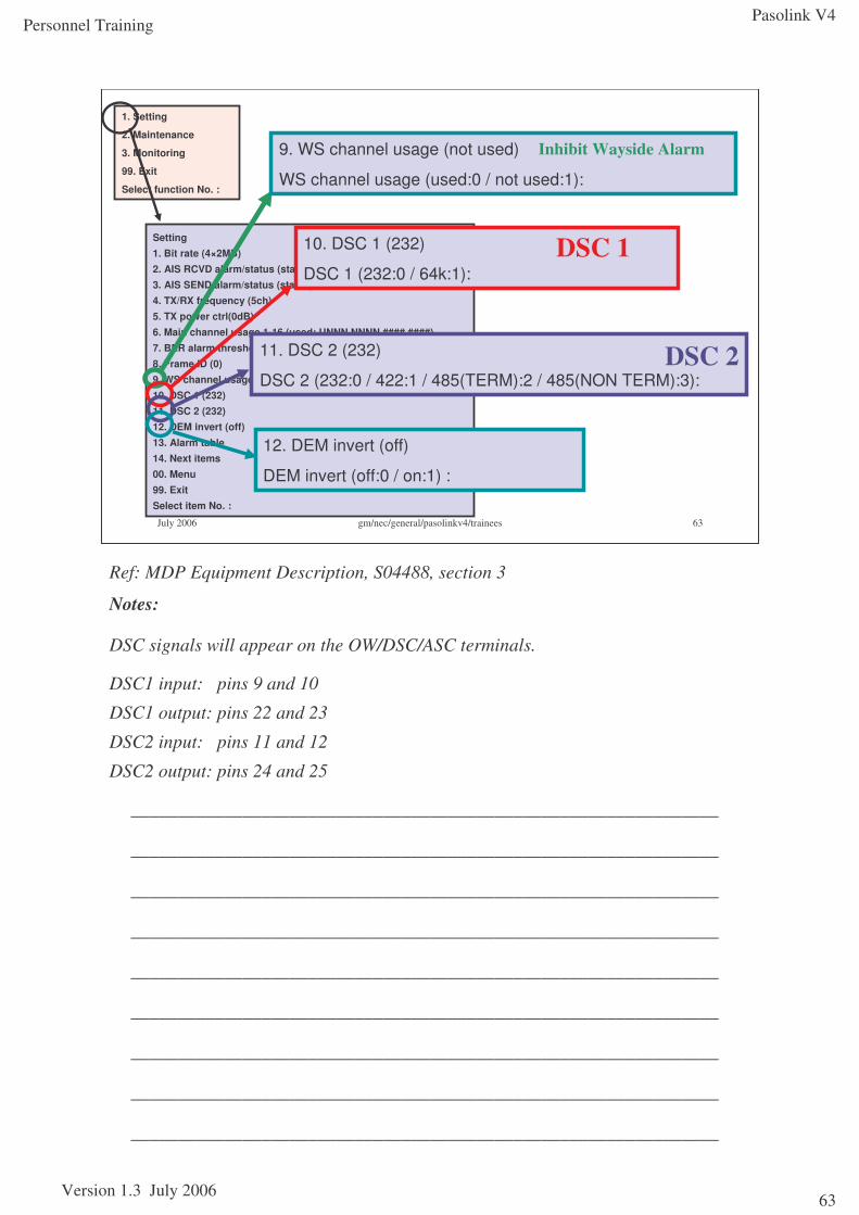
9. WS channel usage (not used)
WS channel usage (used:0 / not used:1):
Inhibit Wayside Alarm
10. DSC 1 (232)
DSC 1 (232:0 / 64k:1):DSC 1
11. DSC 2 (232)
DSC 2 (232:0 / 422:1 / 485(TERM):2 / 485(NON TERM):3):DSC 2
12. DEM invert (off)
DEM invert (off:0 / on:1) :
Ref: MDP Equipment Description, S04488, section 3
Notes:
DSC signals will appear on the OW/DSC/ASC terminals.
DSC1 input: pins 9 and 10
DSC1 output: pins 22 and 23
DSC2 input: pins 11 and 12
DSC2 output: pins 24 and 25
_______________________________________________________________
_______________________________________________________________
_______________________________________________________________
_______________________________________________________________
_______________________________________________________________
_______________________________________________________________
_______________________________________________________________
_______________________________________________________________
_______________________________________________________________
Pasolink V4
Version 1.3 July 2006
Personnel Training
64
Link commissioning
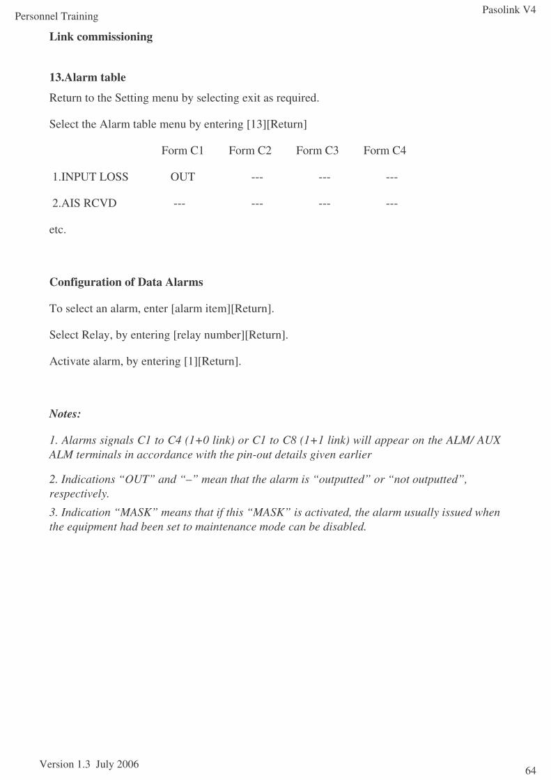
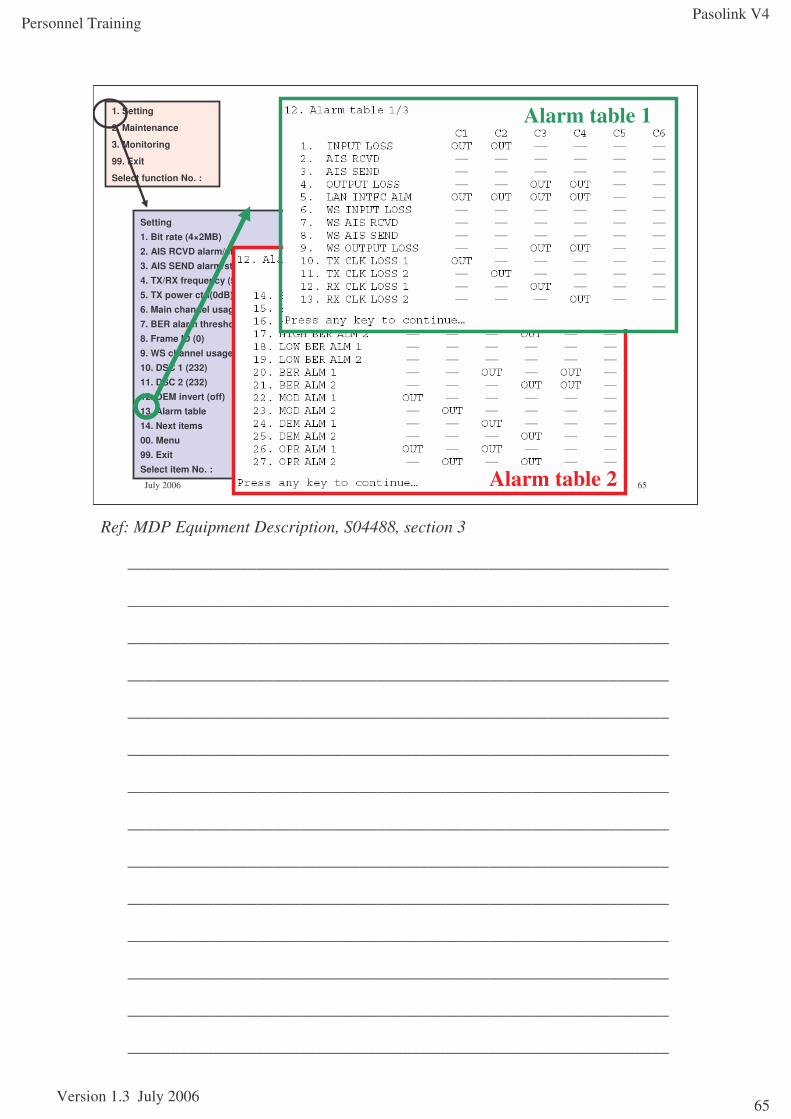
13.Alarm table
Return to the Setting menu by selecting exit as required.
Select the Alarm table menu by entering [13][Return]
Form C1 Form C2 Form C3 Form C4
1.INPUT LOSS OUT --- --- ---
2.AIS RCVD --- --- --- ---
etc.
Configuration of Data Alarms
To select an alarm, enter [alarm item][Return].
Select Relay, by entering [relay number][Return].
Activate alarm, by entering [1][Return].
Notes:
1. Alarms signals C1 to C4 (1+0 link) or C1 to C8 (1+1 link) will appear on the ALM/ AUX ALM terminals in accordance with the pin-out details given earlier
2. Indications “OUT” and “–” mean that the alarm is “outputted” or “not outputted”, respectively.
3. Indication “MASK” means that if this “MASK” is activated, the alarm usually issued when the equipment had been set to maintenance mode can be disabled.
Pasolink V4
Version 1.3 July 2006
Personnel Training
65
July 2006 gm/nec/general/pasolinkv4/trainees 65
Setting1. Bit rate (4×2MB)2. AIS RCVD alarm/status (status)3. AIS SEND alarm/status (status)4. TX/RX frequency (5ch)5. TX power ctrl(0dB)6. Main channel usage 1-16 (used: UNNN NNNN #### ####)
7. BER alarm threshold (10-4)8. Frame ID (0)9. WS channel usage (not used)10. DSC 1 (232)11. DSC 2 (232)12. DEM invert (off)13. Alarm table14. Next items00. Menu99. ExitSelect item No. :
1. Setting
2. Maintenance
3. Monitoring
99. Exit
Select function No. :
Alarm table 2
Alarm table 1
Ref: MDP Equipment Description, S04488, section 3
_______________________________________________________________
_______________________________________________________________
_______________________________________________________________
_______________________________________________________________
_______________________________________________________________
_______________________________________________________________
_______________________________________________________________
_______________________________________________________________
_______________________________________________________________
_______________________________________________________________
_______________________________________________________________
_______________________________________________________________
_______________________________________________________________
_______________________________________________________________
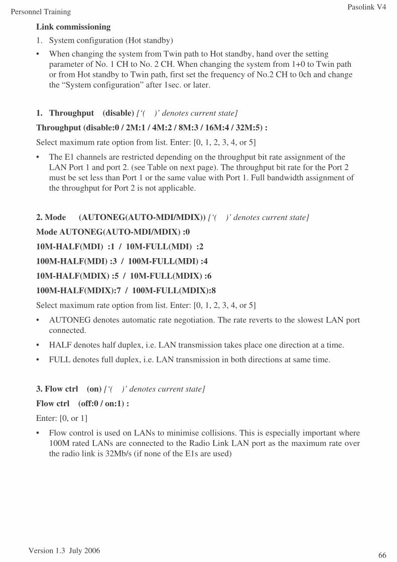
Pasolink V4
Version 1.3 July 2006
Personnel Training
66
Link commissioning1. System configuration (Hot standby)
• When changing the system from Twin path to Hot standby, hand over the setting parameter of No. 1 CH to No. 2 CH. When changing the system from 1+0 to Twin path or from Hot standby to Twin path, first set the frequency of No.2 CH to 0ch and change the “System configuration” after 1sec. or later.
1. Throughput (disable) [‘( )’ denotes current state]
Throughput (disable:0 / 2M:1 / 4M:2 / 8M:3 / 16M:4 / 32M:5) :
Select maximum rate option from list. Enter: [0, 1, 2, 3, 4, or 5]
• The E1 channels are restricted depending on the throughput bit rate assignment of the LAN Port 1 and port 2. (see Table on next page). The throughput bit rate for the Port 2 must be set less than Port 1 or the same value with Port 1. Full bandwidth assignment of the throughput for Port 2 is not applicable.
2. Mode (AUTONEG(AUTO-MDI/MDIX)) [‘( )’ denotes current state]
Mode AUTONEG(AUTO-MDI/MDIX) :0
10M-HALF(MDI) :1 / 10M-FULL(MDI) :2
100M-HALF(MDI) :3 / 100M-FULL(MDI) :4
10M-HALF(MDIX) :5 / 10M-FULL(MDIX) :6
100M-HALF(MDIX):7 / 100M-FULL(MDIX):8
Select maximum rate option from list. Enter: [0, 1, 2, 3, 4, or 5]
• AUTONEG denotes automatic rate negotiation. The rate reverts to the slowest LAN port connected.
• HALF denotes half duplex, i.e. LAN transmission takes place one direction at a time.
• FULL denotes full duplex, i.e. LAN transmission in both directions at same time.
3. Flow ctrl (on) [‘( )’ denotes current state]
Flow ctrl (off:0 / on:1) :
Enter: [0, or 1]
• Flow control is used on LANs to minimise collisions. This is especially important where 100M rated LANs are connected to the Radio Link LAN port as the maximum rate over the radio link is 32Mb/s (if none of the E1s are used)
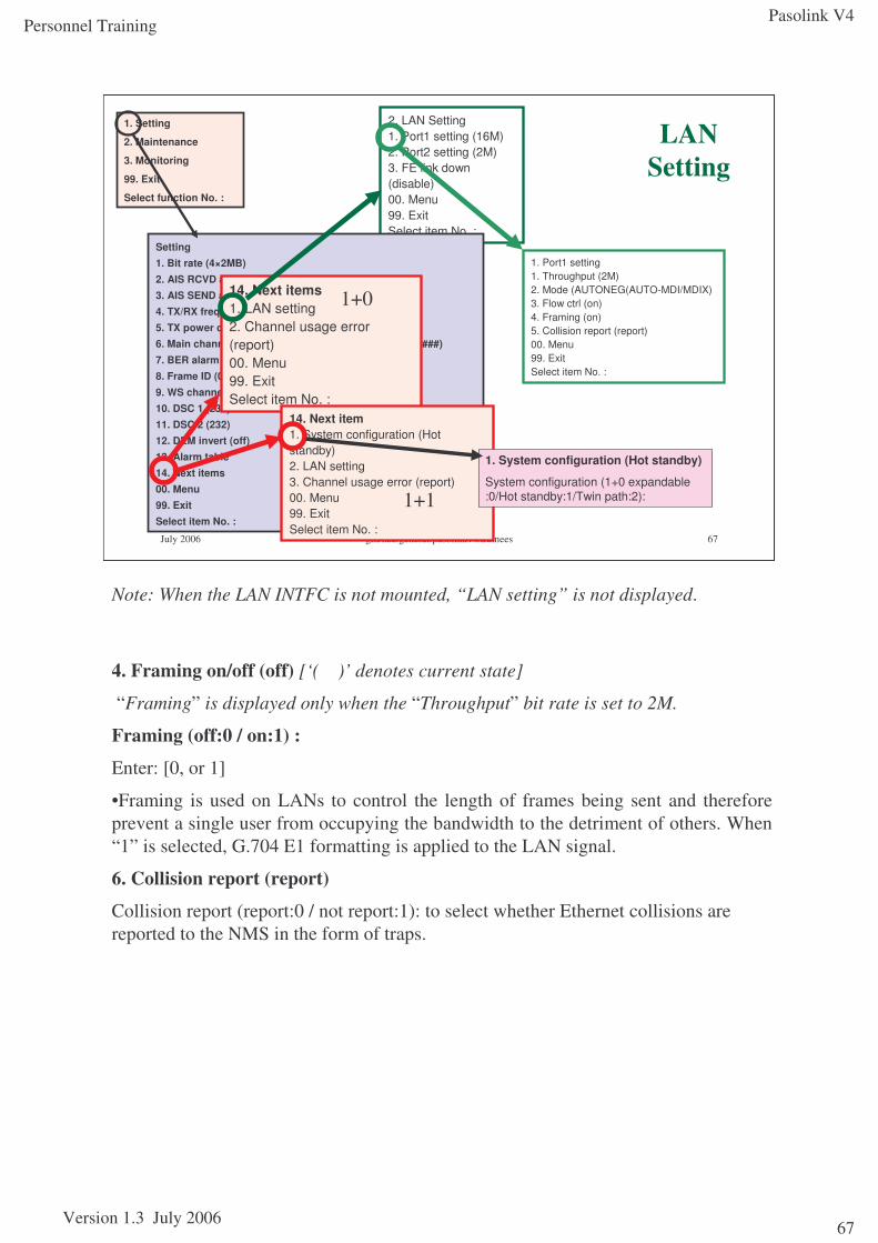
Pasolink V4
Version 1.3 July 2006
Personnel Training
67
July 2006 gm/nec/general/pasolinkv4/trainees 67
2. LAN Setting1. Port1 setting (16M)2. Port2 setting (2M)3. FE link down (disable)00. Menu99. ExitSelect item No. :
Setting1. Bit rate (4×2MB)2. AIS RCVD alarm/status (status)3. AIS SEND alarm/status (status)4. TX/RX frequency (5ch)5. TX power ctrl(0dB)6. Main channel usage 1-16 (used: UNNN NNNN #### ####)
7. BER alarm threshold (10-4)8. Frame ID (0)9. WS channel usage (not used)10. DSC 1 (232)11. DSC 2 (232)12. DEM invert (off)13. Alarm table14. Next items00. Menu99. ExitSelect item No. :
1. Setting
2. Maintenance
3. Monitoring
99. Exit
Select function No. :
LAN Setting
14. Next items1. LAN setting2. Channel usage error (report)00. Menu99. ExitSelect item No. :
14. Next item1. System configuration (Hot standby)2. LAN setting3. Channel usage error (report)00. Menu99. ExitSelect item No. :
1+1
1+0
1. System configuration (Hot standby)
System configuration (1+0 expandable :0/Hot standby:1/Twin path:2):
1. Port1 setting1. Throughput (2M)2. Mode (AUTONEG(AUTO-MDI/MDIX)3. Flow ctrl (on)4. Framing (on)5. Collision report (report)00. Menu99. ExitSelect item No. :
Note: When the LAN INTFC is not mounted, “LAN setting” is not displayed.
4. Framing on/off (off) [‘( )’ denotes current state]
“Framing” is displayed only when the “Throughput” bit rate is set to 2M.
Framing (off:0 / on:1) :
Enter: [0, or 1]
•Framing is used on LANs to control the length of frames being sent and therefore prevent a single user from occupying the bandwidth to the detriment of others. When “1” is selected, G.704 E1 formatting is applied to the LAN signal.
6. Collision report (report)
Collision report (report:0 / not report:1): to select whether Ethernet collisions are reported to the NMS in the form of traps.

Pasolink V4
Version 1.3 July 2006
Personnel Training
68
Link commissioning3. FE link down (disable)FE link down (disable:0 / enable:1):
• The local LAN port is shut off by a far-end LAN Link failure, when “enable” is selected. In any case, a radio link failure also causes LAN ports to be shut down.
2. Channel usage error (report)Channel usage error (report:0 / not report:1):
• This setting is effective for both Main Channel (2Mb/s) usage error and WS channel usage error. It is used to indicate when traffic is connected to an inhibited channel.
System (10/100BASE-T) Applicable Traffic CH Number to use 2MBPort 1 Port 2
2 x 2MB disable disable CH1, CH22M disable CH22M 2M -4M disable -
4 x 2MB disable disable CH1, CH2, CH3, CH42M disable CH2, CH3, CH42M 2M CH2, CH44M disable CH3, CH44M 2M CH44M 4M -8M disable -
8 x 2MB disable disable CH1, CH2, CH3, CH4, CH5, CH6, CH7, CH82M disable CH2, CH3, CH4, CH5, CH6, CH7, CH82M 2M CH2, CH3, CH4, CH6, CH7, CH84M disable CH3, CH4, CH5, CH6, CH7, CH84M 2M CH3, CH4, CH6, CH7, CH84M 4M CH3, CH4, CH7, CH88M disable CH5, CH6, CH7, CH88M 2M CH6, CH7, CH88M 4M CH7, CH88M 8M -16M disable -
16 x 2MB disable disable CH1 – CH162M disable CH2 – CH162M 2M CH2 - CH8, CH10 - CH164M disable CH3 - CH164M 2M CH3 - CH8, CH10 - CH164M 4M CH3 - CH8, CH11 - CH168M disable CH5 - CH168M 2M CH5- CH8, CH10 - CH168M 4M CH5 - CH8, CH11 - CH168M 8M CH5 - CH8, CH13 - CH1616M disable CH9 - CH1616M 2M CH10, CH11, CH12, CH13, CH14, CH15, CH1616M 4M CH11, CH12, CH13, CH14, CH15, CH1616M 8M CH13, CH14, CH15, CH1616M 16M -32M disable -
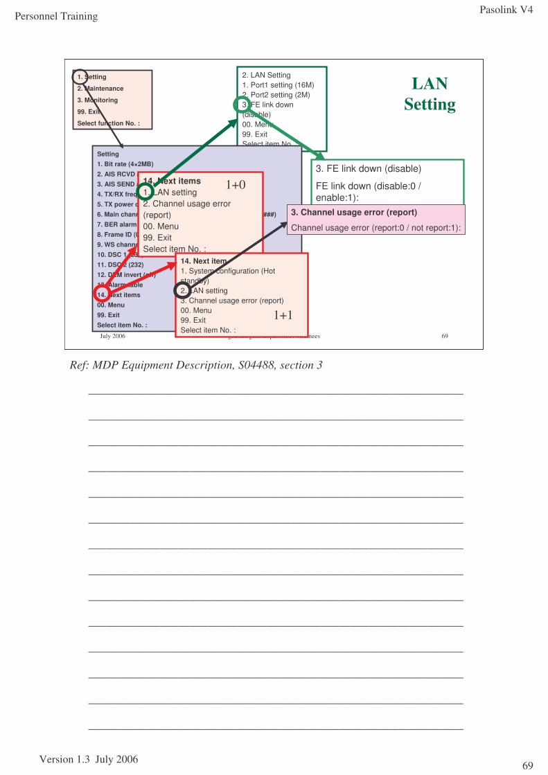
Pasolink V4
Version 1.3 July 2006
Personnel Training
69
July 2006 gm/nec/general/pasolinkv4/trainees 69
2. LAN Setting1. Port1 setting (16M)2. Port2 setting (2M)3. FE link down (disable)00. Menu99. ExitSelect item No. :
Setting1. Bit rate (4×2MB)2. AIS RCVD alarm/status (status)3. AIS SEND alarm/status (status)4. TX/RX frequency (5ch)5. TX power ctrl(0dB)6. Main channel usage 1-16 (used: UNNN NNNN #### ####)
7. BER alarm threshold (10-4)8. Frame ID (0)9. WS channel usage (not used)10. DSC 1 (232)11. DSC 2 (232)12. DEM invert (off)13. Alarm table14. Next items00. Menu99. ExitSelect item No. :
1. Setting
2. Maintenance
3. Monitoring
99. Exit
Select function No. :
LAN Setting
14. Next items1. LAN setting2. Channel usage error (report)00. Menu99. ExitSelect item No. :
14. Next item1. System configuration (Hot standby)2. LAN setting3. Channel usage error (report)00. Menu99. ExitSelect item No. :
1+1
1+03. FE link down (disable)
FE link down (disable:0 / enable:1):
3. Channel usage error (report)
Channel usage error (report:0 / not report:1):
Ref: MDP Equipment Description, S04488, section 3
_______________________________________________________________
_______________________________________________________________
_______________________________________________________________
_______________________________________________________________
_______________________________________________________________
_______________________________________________________________
_______________________________________________________________
_______________________________________________________________
_______________________________________________________________
_______________________________________________________________
_______________________________________________________________
_______________________________________________________________
_______________________________________________________________
_______________________________________________________________
Pasolink V4
Version 1.3 July 2006
Personnel Training
70
Link commissioning - Link PanningAntenna Polarisation Check
Before commencing any panning, confirm that the polarisation is the same at each antenna and it agrees with the requirement of the Link Deployment Form.
AGC Voltage Optimisation
Procedure for 7/8 GHz band ODU1 At each station, open the cover of the ODU
2 At each station, connect voltmeter cables to MON and GND jacks using banana clips
3 At each station, set the rotary switch “MON SEL” to position“1”,
4 At each station, adjust azimuth and elevation angle for the antenna direction alternately so that the voltage measuring value becomes maximum.
Procedure for 13-38 GHz band ODU1 At each station, remove the cap from the RX LEV MON jack
2 At each station, connect voltmeter cables to RX LEV MON jack using F-type plug
A. USING NEW TYPE BRACKET
AZIMUTH ANGLE ADJUSTMENT
•Loosen bolts (1 in Fig)
•Adjust the azimuth angle by bolt (2 in Fig), secure bolts loosened in steps above
ELEVATION ANGLE ADJUSTMENT
•Loosen bolts (3 in Fig)
•Adjust the elevation angle by bolt (4 in Fig), secure bolts loosened in steps above
B. USING OLD TYPE BRACKET
AZIMUTH ANGLE ADJUSTMENT
•Loosen nuts (1 in Fig)
•Adjust azimuth angle by adjusting nut (2 in Fig). Secure nuts loosened
ELEVATION ANGLE ADJUSTMENT
•Loosen nut (3 in Fig)
•Loosen three nuts (4 in Fig)
•Adjust elevation angle by adjusting nut (3 in Fig). Secure nut loosened
4 At each station, disconnect digital multimeter or OW/RX LEV MONITOR from RX LEV MON jacks,
5 At each station, reconnect the cap removed and record the results
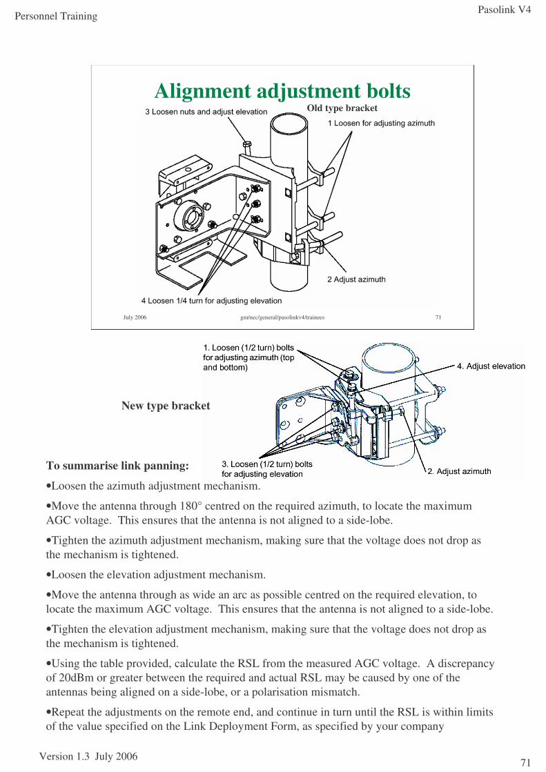
Pasolink V4
Version 1.3 July 2006
Personnel Training
71
July 2006 gm/nec/general/pasolinkv4/trainees 71
Alignment adjustment boltsOld type bracket
New type bracket
To summarise link panning:
•Loosen the azimuth adjustment mechanism.
•Move the antenna through 180° centred on the required azimuth, to locate the maximum AGC voltage. This ensures that the antenna is not aligned to a side-lobe.
•Tighten the azimuth adjustment mechanism, making sure that the voltage does not drop as the mechanism is tightened.
•Loosen the elevation adjustment mechanism.
•Move the antenna through as wide an arc as possible centred on the required elevation, to locate the maximum AGC voltage. This ensures that the antenna is not aligned to a side-lobe.
•Tighten the elevation adjustment mechanism, making sure that the voltage does not drop as the mechanism is tightened.
•Using the table provided, calculate the RSL from the measured AGC voltage. A discrepancy of 20dBm or greater between the required and actual RSL may be caused by one of the antennas being aligned on a side-lobe, or a polarisation mismatch.
•Repeat the adjustments on the remote end, and continue in turn until the RSL is within limits of the value specified on the Link Deployment Form, as specified by your company
Pasolink V4
Version 1.3 July 2006
Personnel Training
72
Link commissioning - Receive Signal Level Measurement
The AGC voltage can be measured via the AGC connector on each ODU. It will range from 1.0V to 4.0V, depending on received level.
AGC Voltage Optimisation
The AGC voltage is measured at the connector at each ODU using a calibrated voltmeter, and suitable interconnecting lead.
For 1+1 systems, optimise the RSL for each path, with the other path disabled.
There is a graph supplied with each ODU, indicating AGC Voltage v Received Signal Level. This is to be used to calculate the measured RSL against the requirements..
If neither sources of information is available, an estimate of the RSL can be derived from the following equation. The accuracy of this method is approximately ±6dB.
RSL = 25 x (AGC – 4.8) where RSL is in dBm and AGC is in Volts
The AGC voltage can also be read via the PC.
From the main menu, select the Monitoring option, by entering [3][Return].
Select Data option, by entering [1][Return].
The receiving AGC voltage level is displayed for each ODU. To refresh the data, enter [1][Return].
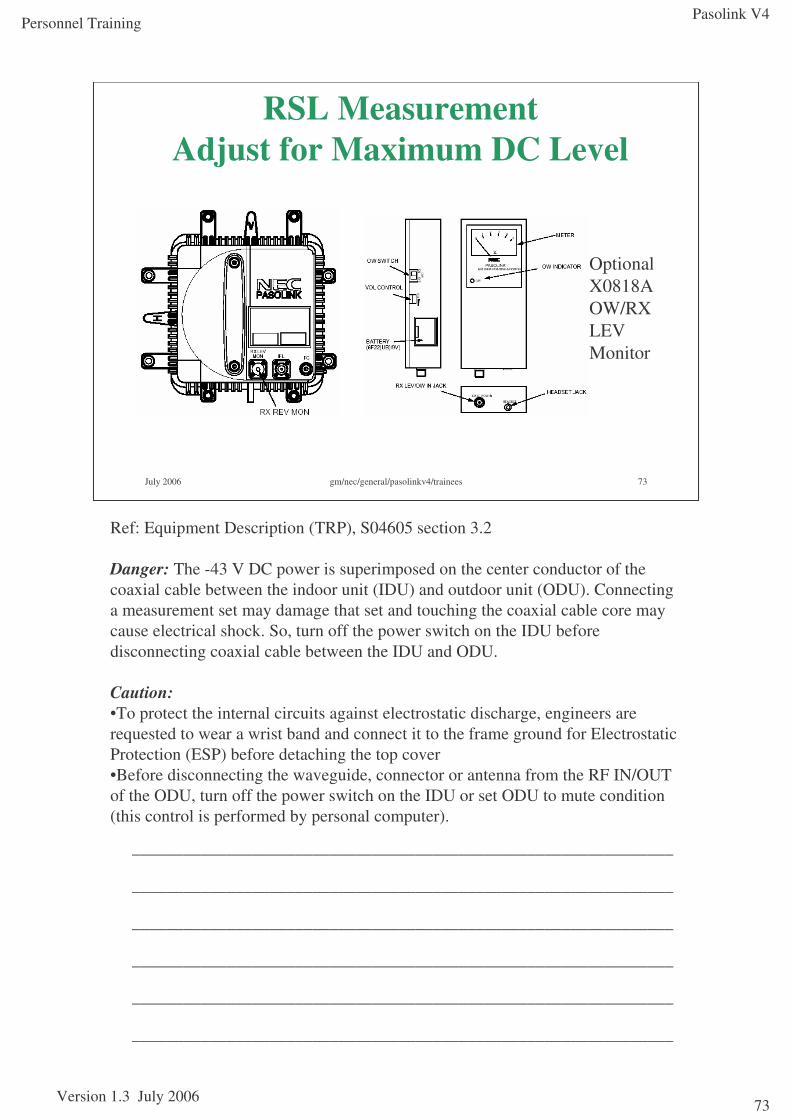
Pasolink V4
Version 1.3 July 2006
Personnel Training
73
July 2006 gm/nec/general/pasolinkv4/trainees 73
RSL Measurement Adjust for Maximum DC Level
Optional X0818A OW/RX LEV Monitor
Ref: Equipment Description (TRP), S04605 section 3.2
Danger: The -43 V DC power is superimposed on the center conductor of the coaxial cable between the indoor unit (IDU) and outdoor unit (ODU). Connecting a measurement set may damage that set and touching the coaxial cable core may cause electrical shock. So, turn off the power switch on the IDU before disconnecting coaxial cable between the IDU and ODU.
Caution: •To protect the internal circuits against electrostatic discharge, engineers are requested to wear a wrist band and connect it to the frame ground for Electrostatic Protection (ESP) before detaching the top cover•Before disconnecting the waveguide, connector or antenna from the RF IN/OUT of the ODU, turn off the power switch on the IDU or set ODU to mute condition (this control is performed by personal computer).
_______________________________________________________________
_______________________________________________________________
_______________________________________________________________
_______________________________________________________________
_______________________________________________________________
_______________________________________________________________
Pasolink V4
Version 1.3 July 2006
Personnel Training
74
Link commissioning - RSL Out of Limits
Where the derived RSL is outside the expected limits of the value specified on the LDF, the reasons for the discrepancy must be established and corrected. (These limits are company specific, but are usually around 4dB)
There are a number of possible reasons for the discrepancy, including equipment calibration. Before suspecting equipment calibration, however, ensure that at least the following have been eliminated.
•Equipment parameters (transmit power and frequency) set up at variance with the LDF requirement.
•Equipment hardware (antenna size, flexi-twist waveguide length) installed at variance with the LDF requirement.
•Antennas cross-polarised.
•Physical damage (distorted waveguide, dented antenna).
•Path obstruction (near field or mid-path).
•Extra temporary path attenuation due to rain or fog.
The in-built radio monitoring facility may prove useful. Use options: monitoring and data The voltage readings should be within the ranges:
The chart shown on the slide is from a typical ODU certificate for a 23GHz ODU. These are delivered with the ODUs.
CHECK ITEM ALLOWABLE RANGE
TX power Depends on transmitter power
• 0 to 4.6 V DC (for 7-38 GHz ODU)
RX level Depends on received signal level
• 0.8 to 4.4 V DC (for 7-38 GHz ODU)
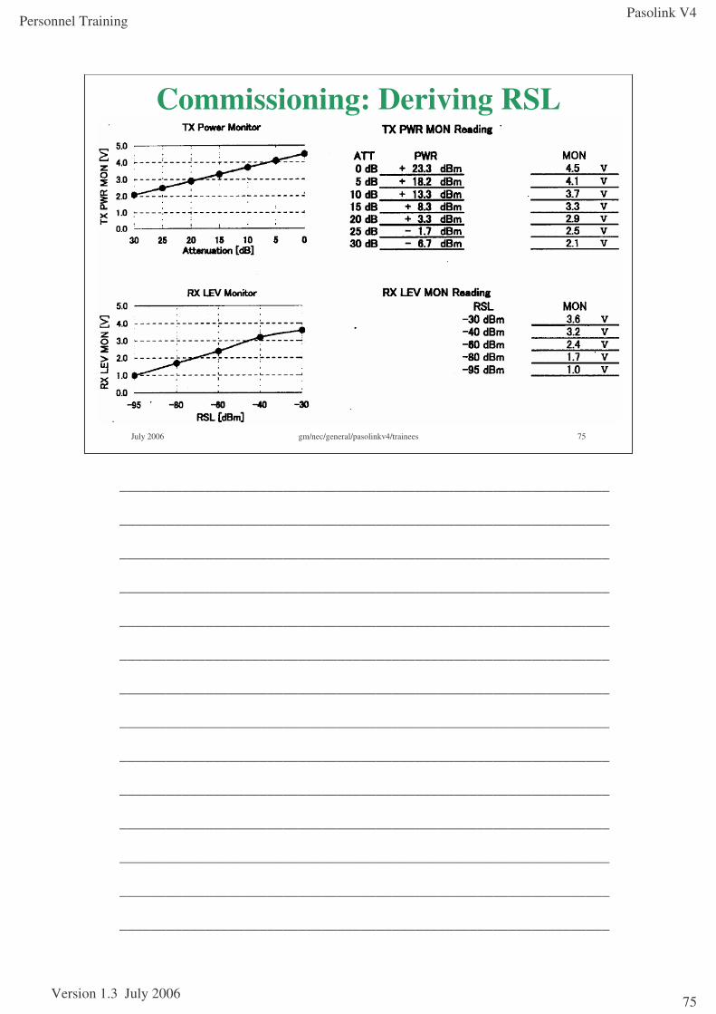
Pasolink V4
Version 1.3 July 2006
Personnel Training
75
July 2006 gm/nec/general/pasolinkv4/trainees 75
Commissioning: Deriving RSL
_______________________________________________________________
_______________________________________________________________
_______________________________________________________________
_______________________________________________________________
_______________________________________________________________
_______________________________________________________________
_______________________________________________________________
_______________________________________________________________
_______________________________________________________________
_______________________________________________________________
_______________________________________________________________
_______________________________________________________________
_______________________________________________________________
_______________________________________________________________
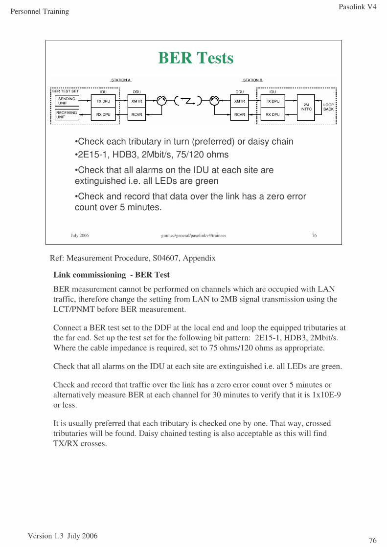
Pasolink V4
Version 1.3 July 2006
Personnel Training
76
July 2006 gm/nec/general/pasolinkv4/trainees 76
BER Tests
•Check each tributary in turn (preferred) or daisy chain•2E15-1, HDB3, 2Mbit/s, 75/120 ohms
•Check that all alarms on the IDU at each site are extinguished i.e. all LEDs are green
•Check and record that data over the link has a zero error count over 5 minutes.
Link commissioning - BER Test
BER measurement cannot be performed on channels which are occupied with LAN traffic, therefore change the setting from LAN to 2MB signal transmission using the LCT/PNMT before BER measurement.
Connect a BER test set to the DDF at the local end and loop the equipped tributaries at the far end. Set up the test set for the following bit pattern: 2E15-1, HDB3, 2Mbit/s. Where the cable impedance is required, set to 75 ohms/120 ohms as appropriate.
Check that all alarms on the IDU at each site are extinguished i.e. all LEDs are green.
Check and record that traffic over the link has a zero error count over 5 minutes or alternatively measure BER at each channel for 30 minutes to verify that it is 1x10E-9 or less.
It is usually preferred that each tributary is checked one by one. That way, crossed tributaries will be found. Daisy chained testing is also acceptable as this will find TX/RX crosses.
Ref: Measurement Procedure, S04607, Appendix
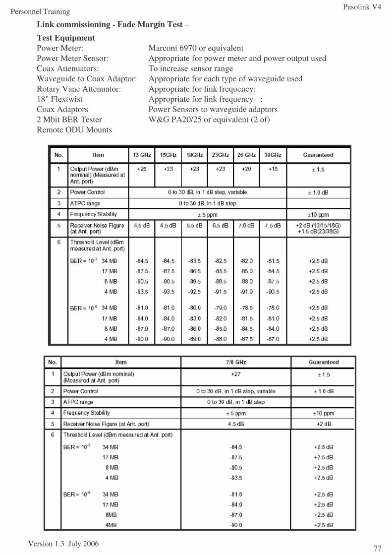
Pasolink V4
Version 1.3 July 2006
Personnel Training
77
Link commissioning - Fade Margin Test –
Test EquipmentPower Meter: Marconi 6970 or equivalent Power Meter Sensor: Appropriate for power meter and power output used Coax Attenuators: To increase sensor rangeWaveguide to Coax Adaptor: Appropriate for each type of waveguide usedRotary Vane Attenuator: Appropriate for link frequency:18" Flextwist Appropriate for link frequency :Coax Adaptors Power Sensors to waveguide adaptors2 Mbit BER Tester W&G PA20/25 or equivalent (2 of)Remote ODU Mounts
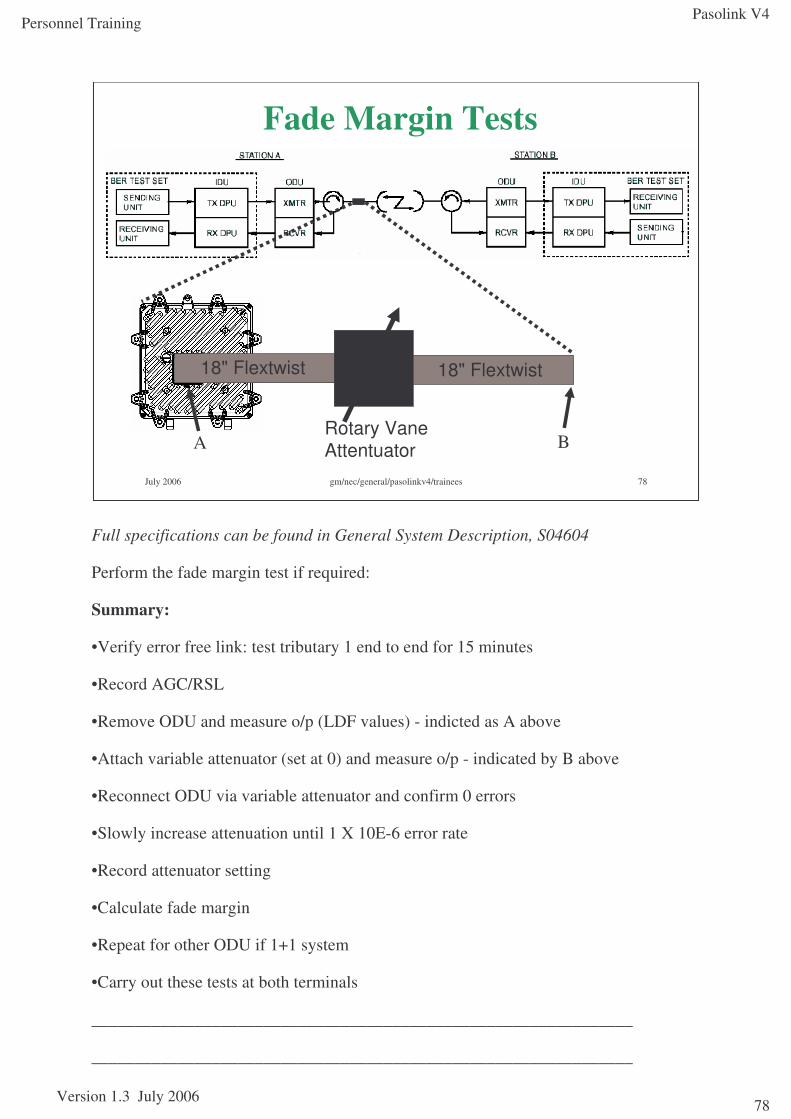
Pasolink V4
Version 1.3 July 2006
Personnel Training
78
July 2006 gm/nec/general/pasolinkv4/trainees 78
Fade Margin Tests
18" Flextwist 18" Flextwist
Rotary Vane AttentuatorA B
Full specifications can be found in General System Description, S04604
Perform the fade margin test if required:
Summary:
•Verify error free link: test tributary 1 end to end for 15 minutes
•Record AGC/RSL
•Remove ODU and measure o/p (LDF values) - indicted as A above
•Attach variable attenuator (set at 0) and measure o/p - indicated by B above
•Reconnect ODU via variable attenuator and confirm 0 errors
•Slowly increase attenuation until 1 X 10E-6 error rate
•Record attenuator setting
•Calculate fade margin
•Repeat for other ODU if 1+1 system
•Carry out these tests at both terminals
_______________________________________________________________
_______________________________________________________________
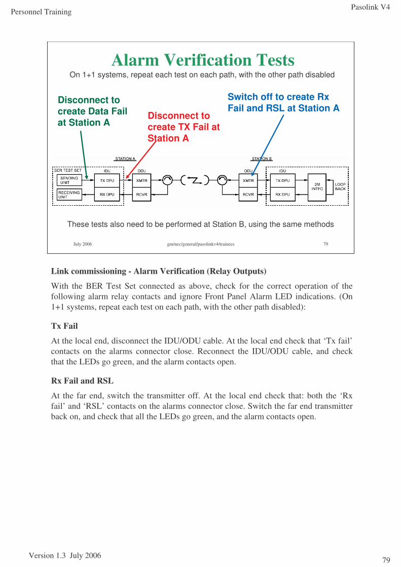
Pasolink V4
Version 1.3 July 2006
Personnel Training
79
July 2006 gm/nec/general/pasolinkv4/trainees 79
Alarm Verification Tests
Disconnect to create TX Fail at Station A
Switch off to create Rx Fail and RSL at Station A
Disconnect to create Data Fail at Station A
On 1+1 systems, repeat each test on each path, with the other path disabled
These tests also need to be performed at Station B, using the same methods
Link commissioning - Alarm Verification (Relay Outputs)
With the BER Test Set connected as above, check for the correct operation of the following alarm relay contacts and ignore Front Panel Alarm LED indications. (On 1+1 systems, repeat each test on each path, with the other path disabled):
Tx Fail
At the local end, disconnect the IDU/ODU cable. At the local end check that ‘Tx fail’contacts on the alarms connector close. Reconnect the IDU/ODU cable, and check that the LEDs go green, and the alarm contacts open.
Rx Fail and RSL
At the far end, switch the transmitter off. At the local end check that: both the ‘Rx fail’ and ‘RSL’ contacts on the alarms connector close. Switch the far end transmitter back on, and check that all the LEDs go green, and the alarm contacts open.
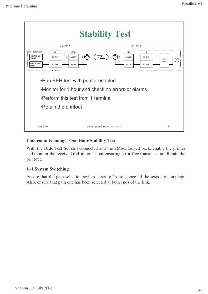
Pasolink V4
Version 1.3 July 2006
Personnel Training
80
July 2006 gm/nec/general/pasolinkv4/trainees 80
Stability Test
•Run BER test with printer enabled
•Monitor for 1 hour and check no errors or alarms
•Perform this test from 1 terminal
•Retain the printout
Link commissioning - One Hour Stability Test
With the BER Test Set still connected and the 2Mb/s looped back, enable the printer and monitor the received traffic for 1 hour ensuring error-free transmission. Retain the printout.
1+1 System Switching
Ensure that the path selection switch is set to ‘Auto’, once all the tests are complete. Also, ensure that path one has been selected at both ends of the link.
Pasolink V4
Version 1.3 July 2006
Personnel Training
81
July 2006 gm/nec/general/pasolinkv4/trainees 81
Module 4Troubleshooting
Section objectivesThis section covers the following:
•Identifying alarms
•Locating faulty units
•Replacing faulty units
Before starting maintenance or troubleshooting procedures, including operation of the OPR SEL SW on the front panel of the equipment, set the equipment to maintenance mode using the LCT/PNMT.
After all maintenance operations have been completed, set MAINT back to OFF.
References:Pasolink V4 User (Instruction) Manual ROI-S0xxxx-051E
Abbreviations ROI-S04491-052EGeneral System Description ROI-S04604-052EMeasurement Procedure ROI-S04607-054ETRP Equipment Description ROI-S04605-054ERadio Frequency Assignment (n GHz) ROI-various-05xE
MDP Equipment Description ROI-S04488-058EInstallation and Initial Lineup ROI-S04606-054E
Pasolink V4 Sub-band Change ProcedurePasolink V4 MTD (1+0 / 1+1) PL035-01
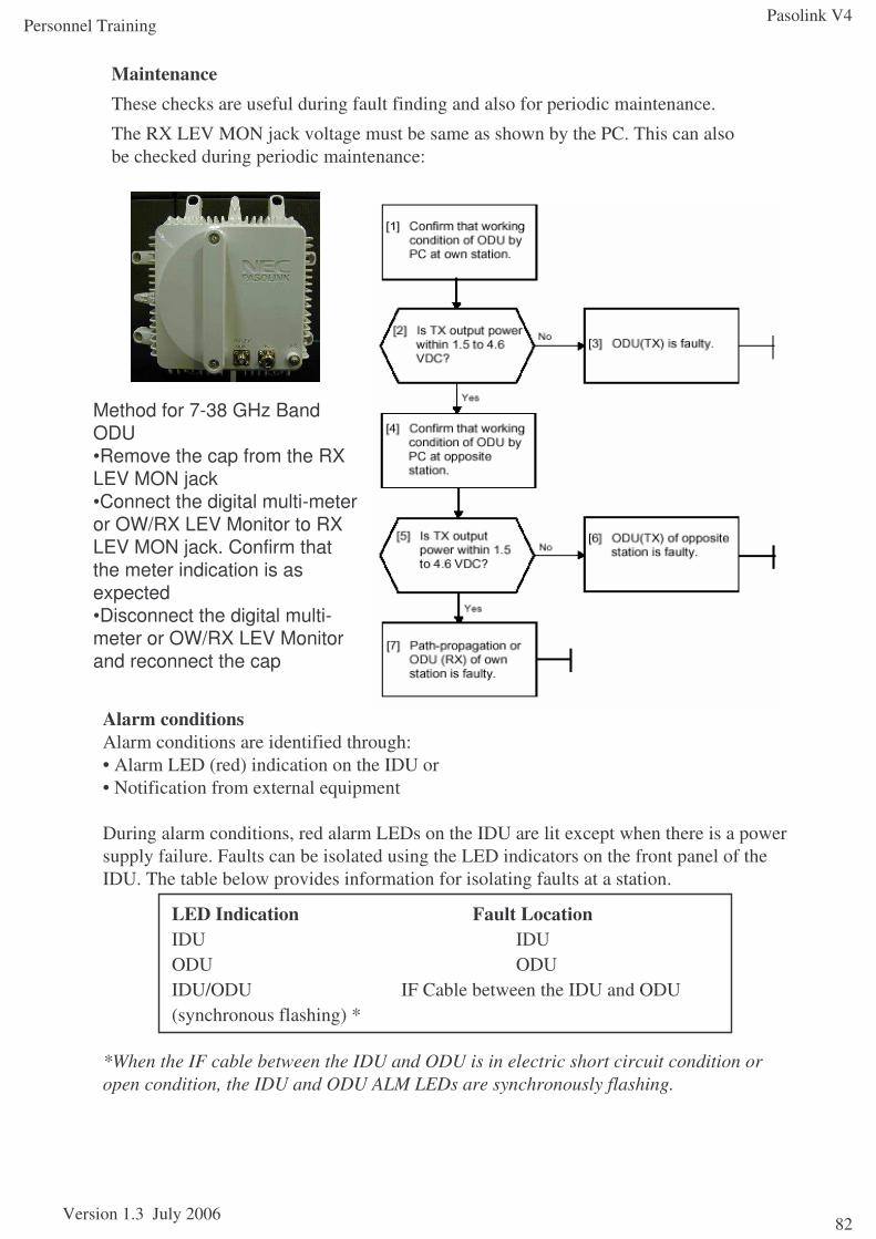
Pasolink V4
Version 1.3 July 2006
Personnel Training
82
MaintenanceThese checks are useful during fault finding and also for periodic maintenance.
The RX LEV MON jack voltage must be same as shown by the PC. This can also be checked during periodic maintenance:
Method for 7-38 GHz Band ODU•Remove the cap from the RX LEV MON jack•Connect the digital multi-meter or OW/RX LEV Monitor to RX LEV MON jack. Confirm that the meter indication is as expected•Disconnect the digital multi-meter or OW/RX LEV Monitor and reconnect the cap
Alarm conditionsAlarm conditions are identified through:• Alarm LED (red) indication on the IDU or• Notification from external equipment
During alarm conditions, red alarm LEDs on the IDU are lit except when there is a power supply failure. Faults can be isolated using the LED indicators on the front panel of the IDU. The table below provides information for isolating faults at a station.
*When the IF cable between the IDU and ODU is in electric short circuit condition or open condition, the IDU and ODU ALM LEDs are synchronously flashing.
LED Indication Fault LocationIDU IDUODU ODUIDU/ODU IF Cable between the IDU and ODU(synchronous flashing) *
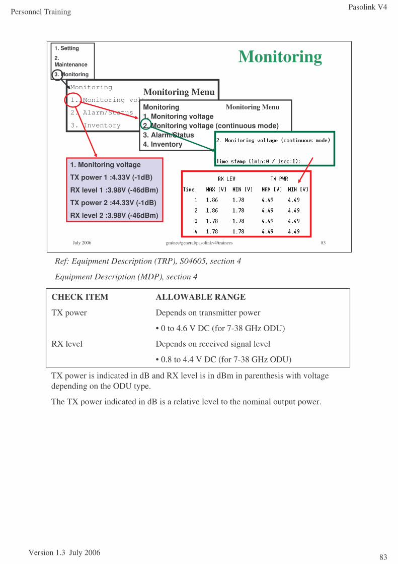
Pasolink V4
Version 1.3 July 2006
Personnel Training
83
July 2006 gm/nec/general/pasolinkv4/trainees 83
Monitoring
1. Monitoring voltage
2. Alarm/Status
3. Inventory
1. Setting
2. Maintenance
3. Monitoring
Monitoring Menu
Monitoring
1. Monitoring voltage
TX power 1 :4.33V (-1dB)
RX level 1 :3.98V (-46dBm)
TX power 2 :44.33V (-1dB)
RX level 2 :3.98V (-46dBm)
Monitoring 1+1
Monitoring1. Monitoring voltage2. Monitoring voltage (continuous mode)3. Alarm/Status4. Inventory
Monitoring Menu
Ref: Equipment Description (TRP), S04605, section 4
Equipment Description (MDP), section 4
CHECK ITEM ALLOWABLE RANGE
TX power Depends on transmitter power
• 0 to 4.6 V DC (for 7-38 GHz ODU)
RX level Depends on received signal level
• 0.8 to 4.4 V DC (for 7-38 GHz ODU)
TX power is indicated in dB and RX level is in dBm in parenthesis with voltage depending on the ODU type.
The TX power indicated in dB is a relative level to the nominal output power.
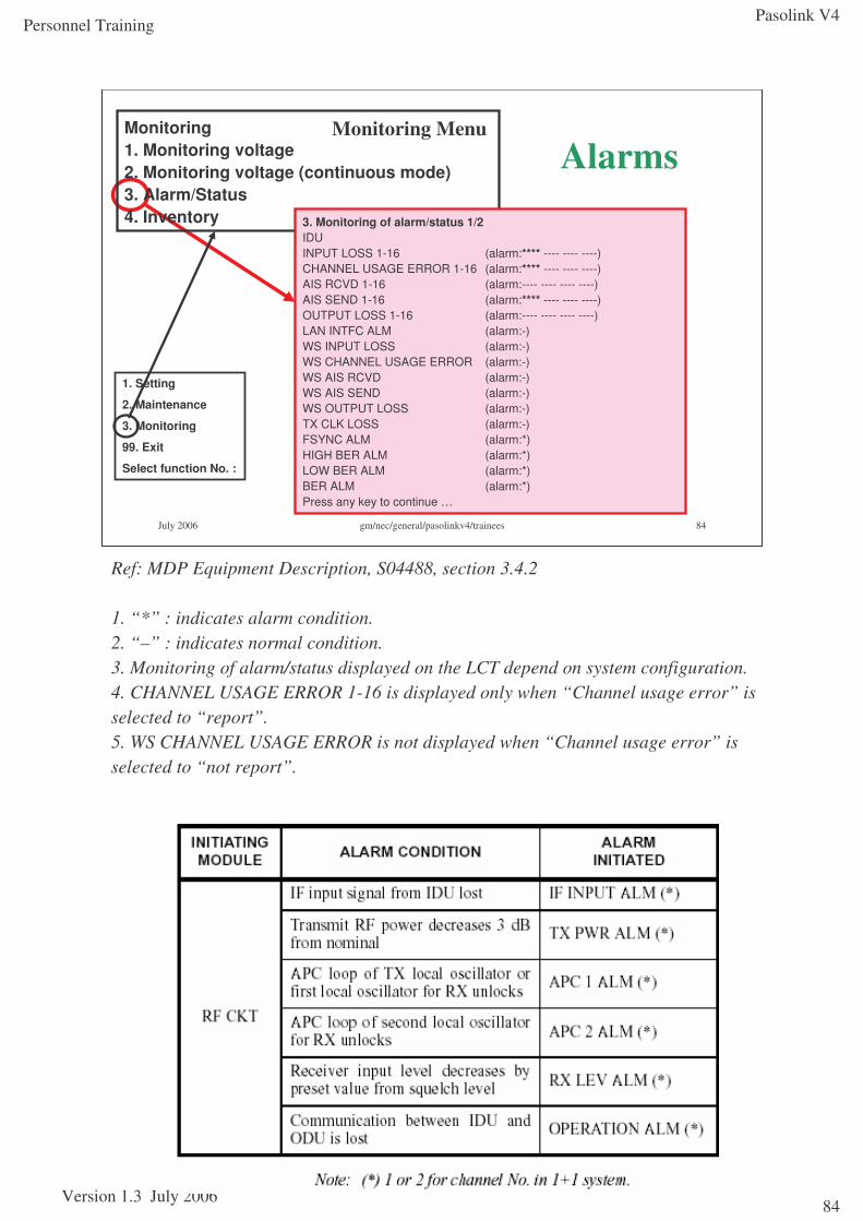
Pasolink V4
Version 1.3 July 2006
Personnel Training
84
July 2006 gm/nec/general/pasolinkv4/trainees 84
1. Setting
2. Maintenance
3. Monitoring
99. Exit
Select function No. :
Alarms Monitoring MenuMonitoring
1. Monitoring voltage2. Monitoring voltage (continuous mode)3. Alarm/Status4. Inventory 3. Monitoring of alarm/status 1/2
IDUINPUT LOSS 1-16 (alarm:**** ---- ---- ----)CHANNEL USAGE ERROR 1-16 (alarm:**** ---- ---- ----)AIS RCVD 1-16 (alarm:---- ---- ---- ----)AIS SEND 1-16 (alarm:**** ---- ---- ----)OUTPUT LOSS 1-16 (alarm:---- ---- ---- ----)LAN INTFC ALM (alarm:-)WS INPUT LOSS (alarm:-)WS CHANNEL USAGE ERROR (alarm:-)WS AIS RCVD (alarm:-)WS AIS SEND (alarm:-)WS OUTPUT LOSS (alarm:-)TX CLK LOSS (alarm:-)FSYNC ALM (alarm:*)HIGH BER ALM (alarm:*)LOW BER ALM (alarm:*)BER ALM (alarm:*)Press any key to continue …
Ref: MDP Equipment Description, S04488, section 3.4.2
1. “*” : indicates alarm condition.2. “–” : indicates normal condition.3. Monitoring of alarm/status displayed on the LCT depend on system configuration.4. CHANNEL USAGE ERROR 1-16 is displayed only when “Channel usage error” is selected to “report”.5. WS CHANNEL USAGE ERROR is not displayed when “Channel usage error” is selected to “not report”.
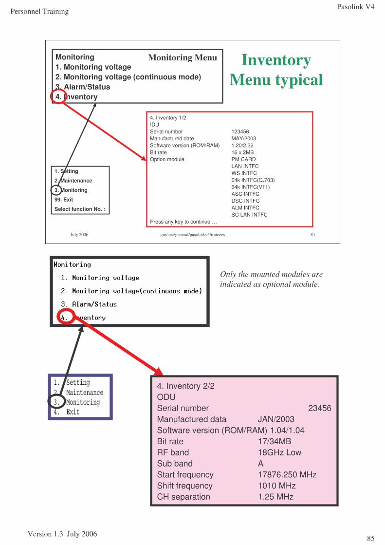
Pasolink V4
Version 1.3 July 2006
Personnel Training
85
July 2006 gm/nec/general/pasolinkv4/trainees 85
Monitoring1. Monitoring voltage2. Monitoring voltage (continuous mode)3. Alarm/Status4. Inventory
Inventory Menu typical
1. Setting
2. Maintenance
3. Monitoring
99. Exit
Select function No. :
Monitoring Menu
4. Inventory 1/2IDUSerial number 123456Manufactured date MAY/2003Software version (ROM/RAM) 1.20/2.32Bit rate 16 x 2MBOption module PM CARD
LAN INTFCWS INTFC64k INTFC(G.703)64k INTFC(V11)ASC INTFCDSC INTFCALM INTFCSC LAN INTFC
Press any key to continue …
Only the mounted modules are indicated as optional module.
4. Inventory 2/2ODUSerial number 23456Manufactured data JAN/2003Software version (ROM/RAM) 1.04/1.04Bit rate 17/34MBRF band 18GHz LowSub band AStart frequency 17876.250 MHzShift frequency 1010 MHzCH separation 1.25 MHz
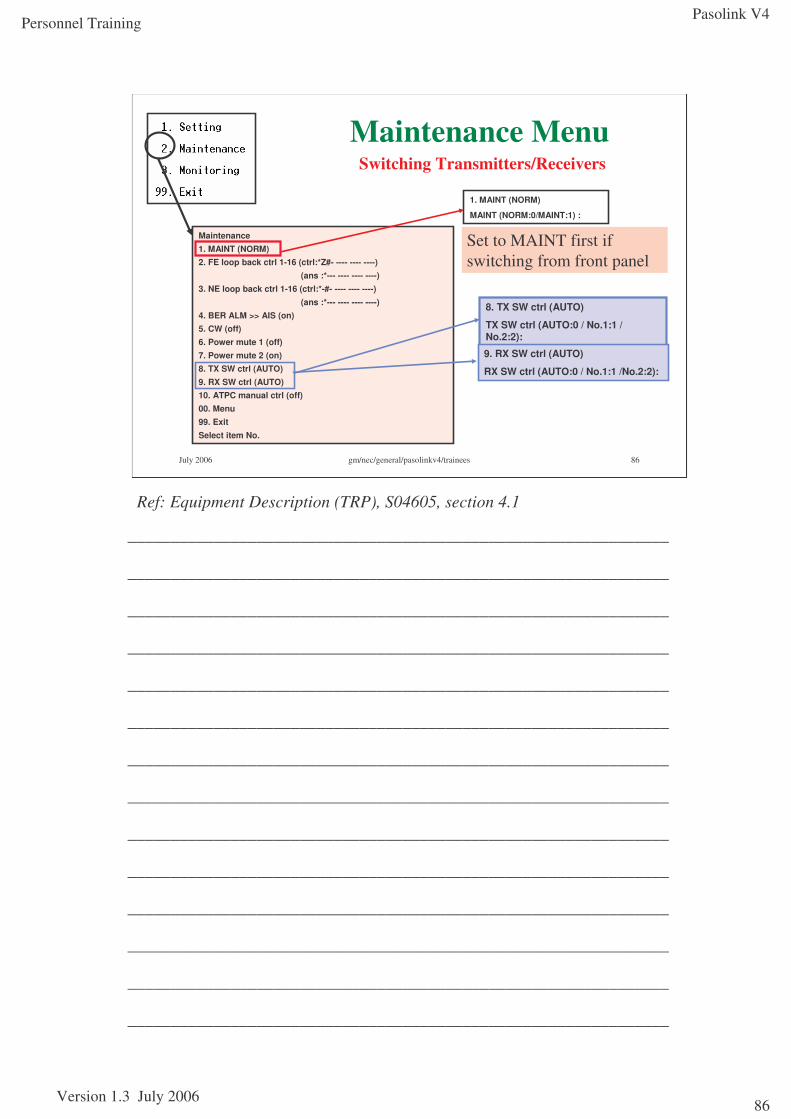
Pasolink V4
Version 1.3 July 2006
Personnel Training
86
July 2006 gm/nec/general/pasolinkv4/trainees 86
Maintenance1. MAINT (NORM)2. FE loop back ctrl 1-16 (ctrl:*Z#- ---- ---- ----)
(ans :*--- ---- ---- ----)3. NE loop back ctrl 1-16 (ctrl:*-#- ---- ---- ----)
(ans :*--- ---- ---- ----)4. BER ALM >> AIS (on)5. CW (off)6. Power mute 1 (off)7. Power mute 2 (on)8. TX SW ctrl (AUTO)9. RX SW ctrl (AUTO)10. ATPC manual ctrl (off)00. Menu99. ExitSelect item No.
Maintenance MenuSwitching Transmitters/Receivers
Set to MAINT first if switching from front panel
1. MAINT (NORM)
MAINT (NORM:0/MAINT:1) :
8. TX SW ctrl (AUTO)
TX SW ctrl (AUTO:0 / No.1:1 / No.2:2):
9. RX SW ctrl (AUTO)
RX SW ctrl (AUTO:0 / No.1:1 /No.2:2):
Ref: Equipment Description (TRP), S04605, section 4.1
_______________________________________________________________
_______________________________________________________________
_______________________________________________________________
_______________________________________________________________
_______________________________________________________________
_______________________________________________________________
_______________________________________________________________
_______________________________________________________________
_______________________________________________________________
_______________________________________________________________
_______________________________________________________________
_______________________________________________________________
_______________________________________________________________
_______________________________________________________________
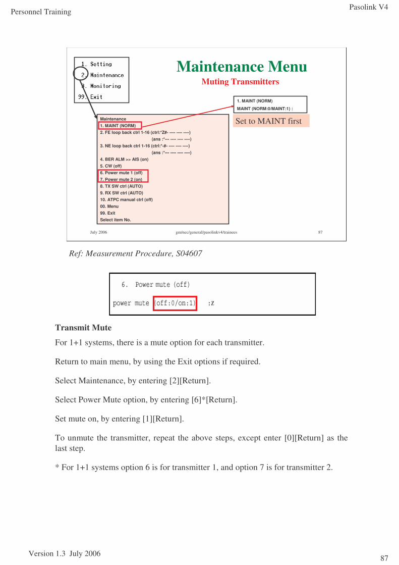
Pasolink V4
Version 1.3 July 2006
Personnel Training
87
July 2006 gm/nec/general/pasolinkv4/trainees 87
Maintenance1. MAINT (NORM)2. FE loop back ctrl 1-16 (ctrl:*Z#- ---- ---- ----)
(ans :*--- ---- ---- ----)3. NE loop back ctrl 1-16 (ctrl:*-#- ---- ---- ----)
(ans :*--- ---- ---- ----)4. BER ALM >> AIS (on)5. CW (off)6. Power mute 1 (off)7. Power mute 2 (on)8. TX SW ctrl (AUTO)9. RX SW ctrl (AUTO)10. ATPC manual ctrl (off)00. Menu99. ExitSelect item No.
Maintenance MenuMuting Transmitters
Set to MAINT first
1. MAINT (NORM)
MAINT (NORM:0/MAINT:1) :
Transmit Mute
For 1+1 systems, there is a mute option for each transmitter.
Return to main menu, by using the Exit options if required.
Select Maintenance, by entering [2][Return].
Select Power Mute option, by entering [6]*[Return].
Set mute on, by entering [1][Return].
To unmute the transmitter, repeat the above steps, except enter [0][Return] as the last step.
* For 1+1 systems option 6 is for transmitter 1, and option 7 is for transmitter 2.
Ref: Measurement Procedure, S04607
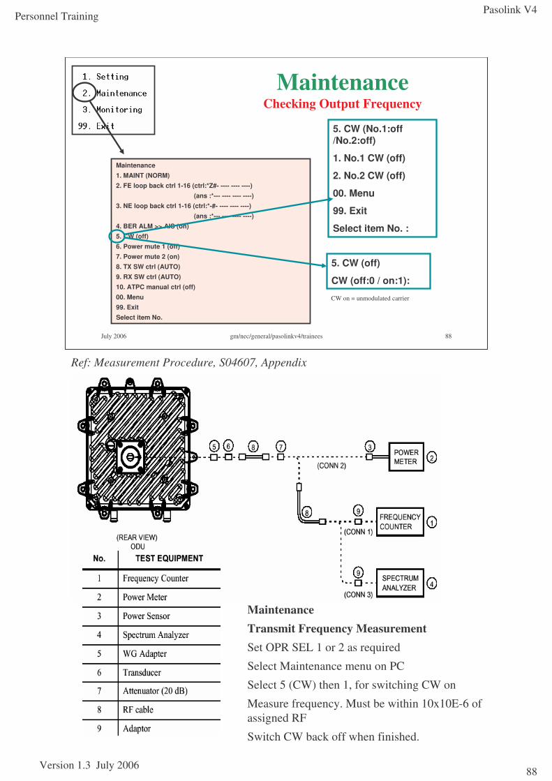
Pasolink V4
Version 1.3 July 2006
Personnel Training
88
July 2006 gm/nec/general/pasolinkv4/trainees 88
Maintenance1. MAINT (NORM)2. FE loop back ctrl 1-16 (ctrl:*Z#- ---- ---- ----)
(ans :*--- ---- ---- ----)3. NE loop back ctrl 1-16 (ctrl:*-#- ---- ---- ----)
(ans :*--- ---- ---- ----)4. BER ALM >> AIS (on)5. CW (off)6. Power mute 1 (off)7. Power mute 2 (on)8. TX SW ctrl (AUTO)9. RX SW ctrl (AUTO)10. ATPC manual ctrl (off)00. Menu99. ExitSelect item No.
MaintenanceChecking Output Frequency
5. CW (off)
CW (off:0 / on:1):
5. CW (No.1:off /No.2:off)
1. No.1 CW (off)
2. No.2 CW (off)
00. Menu
99. Exit
Select item No. :
CW on = unmodulated carrier
MaintenanceTransmit Frequency MeasurementSet OPR SEL 1 or 2 as required
Select Maintenance menu on PC
Select 5 (CW) then 1, for switching CW on
Measure frequency. Must be within 10x10E-6 of assigned RF
Switch CW back off when finished.
Ref: Measurement Procedure, S04607, Appendix
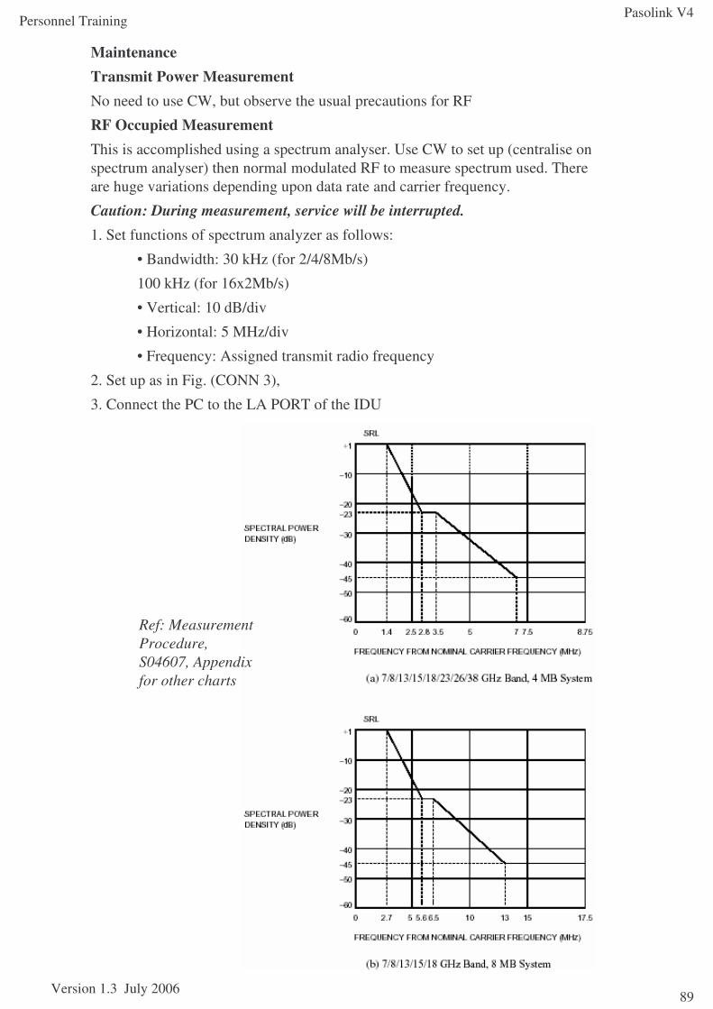
Pasolink V4
Version 1.3 July 2006
Personnel Training
89
MaintenanceTransmit Power MeasurementNo need to use CW, but observe the usual precautions for RF
RF Occupied MeasurementThis is accomplished using a spectrum analyser. Use CW to set up (centralise on spectrum analyser) then normal modulated RF to measure spectrum used. There are huge variations depending upon data rate and carrier frequency.
Caution: During measurement, service will be interrupted.1. Set functions of spectrum analyzer as follows:
• Bandwidth: 30 kHz (for 2/4/8Mb/s)
100 kHz (for 16x2Mb/s)
• Vertical: 10 dB/div
• Horizontal: 5 MHz/div
• Frequency: Assigned transmit radio frequency
2. Set up as in Fig. (CONN 3),
3. Connect the PC to the LA PORT of the IDU
Ref: Measurement Procedure, S04607, Appendix for other charts
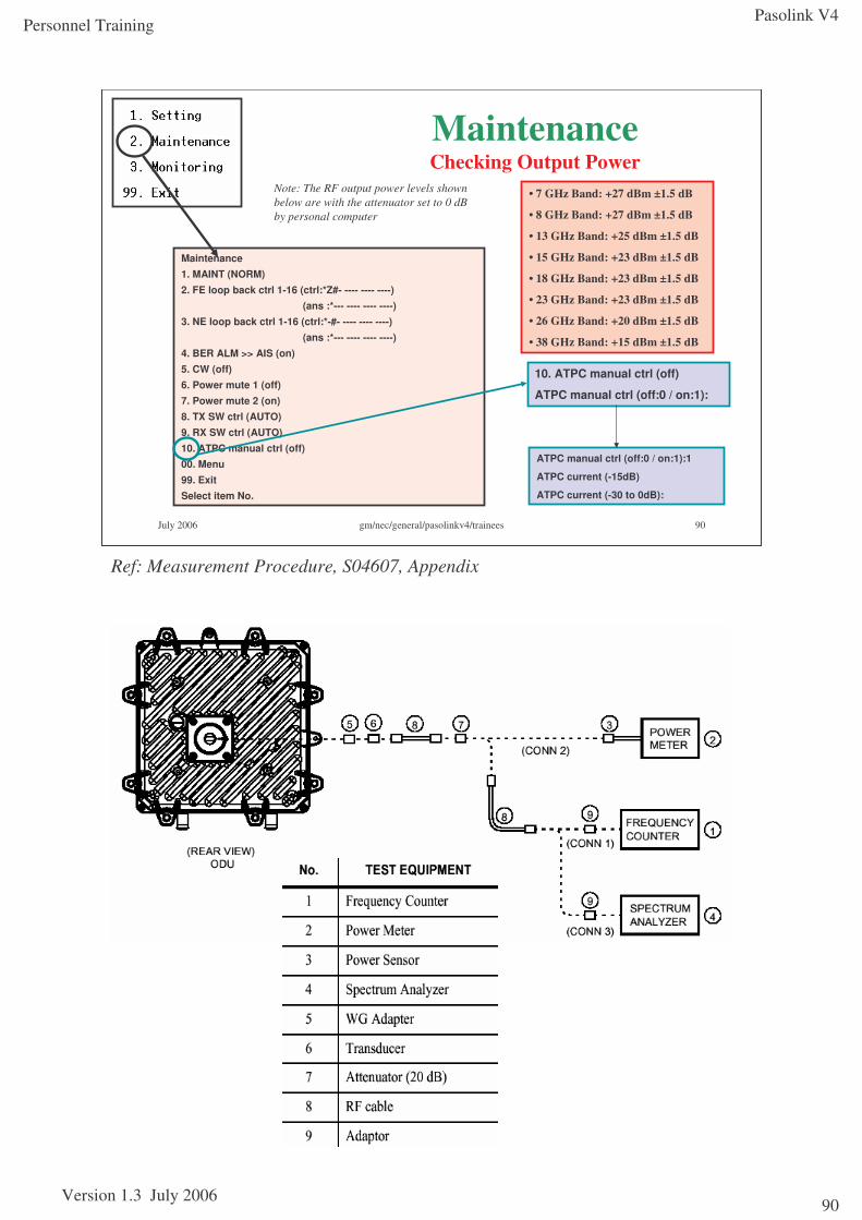
Pasolink V4
Version 1.3 July 2006
Personnel Training
90
July 2006 gm/nec/general/pasolinkv4/trainees 90
Maintenance1. MAINT (NORM)2. FE loop back ctrl 1-16 (ctrl:*Z#- ---- ---- ----)
(ans :*--- ---- ---- ----)3. NE loop back ctrl 1-16 (ctrl:*-#- ---- ---- ----)
(ans :*--- ---- ---- ----)4. BER ALM >> AIS (on)5. CW (off)6. Power mute 1 (off)7. Power mute 2 (on)8. TX SW ctrl (AUTO)9. RX SW ctrl (AUTO)10. ATPC manual ctrl (off)00. Menu99. ExitSelect item No.
MaintenanceChecking Output Power
• 7 GHz Band: +27 dBm ±1.5 dB
• 8 GHz Band: +27 dBm ±1.5 dB
• 13 GHz Band: +25 dBm ±1.5 dB
• 15 GHz Band: +23 dBm ±1.5 dB
• 18 GHz Band: +23 dBm ±1.5 dB
• 23 GHz Band: +23 dBm ±1.5 dB
• 26 GHz Band: +20 dBm ±1.5 dB
• 38 GHz Band: +15 dBm ±1.5 dB
Note: The RF output power levels shown below are with the attenuator set to 0 dB by personal computer
10. ATPC manual ctrl (off)
ATPC manual ctrl (off:0 / on:1):
ATPC manual ctrl (off:0 / on:1):1
ATPC current (-15dB)
ATPC current (-30 to 0dB):
Ref: Measurement Procedure, S04607, Appendix
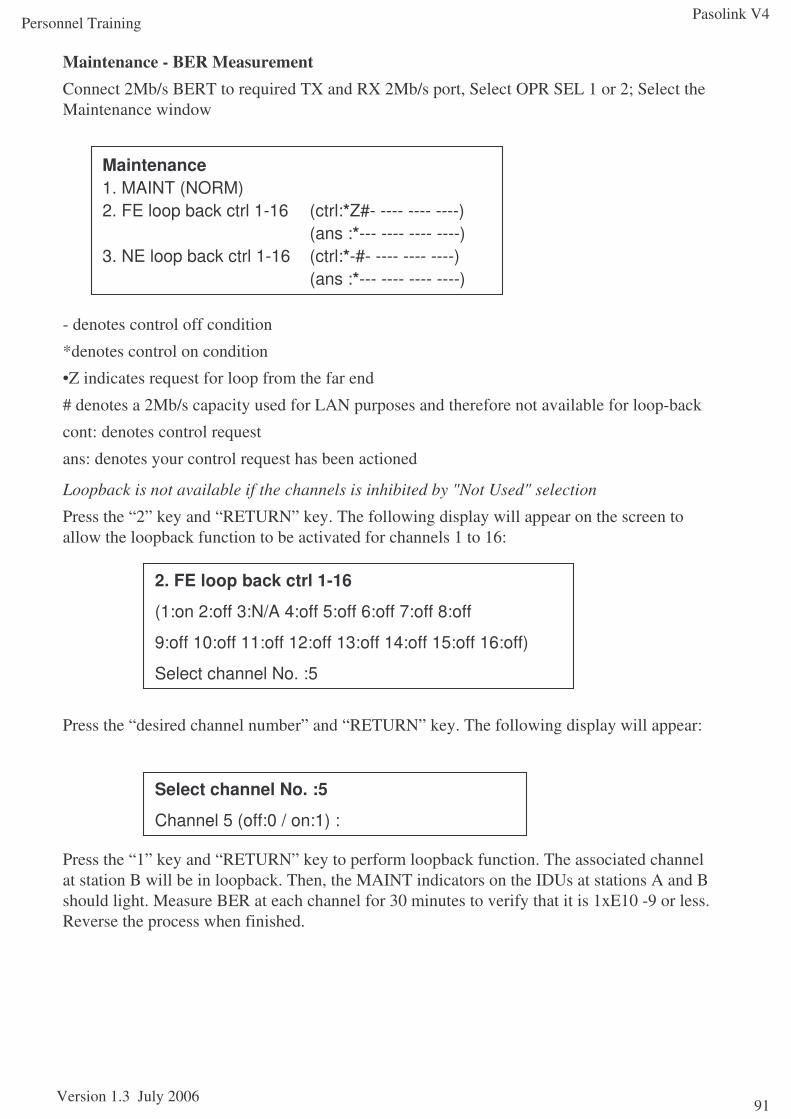
Pasolink V4
Version 1.3 July 2006
Personnel Training
91
Maintenance - BER MeasurementConnect 2Mb/s BERT to required TX and RX 2Mb/s port, Select OPR SEL 1 or 2; Select the Maintenance window
- denotes control off condition
*denotes control on condition
•Z indicates request for loop from the far end
# denotes a 2Mb/s capacity used for LAN purposes and therefore not available for loop-back
cont: denotes control request
ans: denotes your control request has been actioned
Loopback is not available if the channels is inhibited by "Not Used" selection
Press the “2” key and “RETURN” key. The following display will appear on the screen to allow the loopback function to be activated for channels 1 to 16:
Press the “desired channel number” and “RETURN” key. The following display will appear:
Press the “1” key and “RETURN” key to perform loopback function. The associated channel at station B will be in loopback. Then, the MAINT indicators on the IDUs at stations A and B should light. Measure BER at each channel for 30 minutes to verify that it is 1xE10 -9 or less. Reverse the process when finished.
Maintenance1. MAINT (NORM)2. FE loop back ctrl 1-16 (ctrl:*Z#- ---- ---- ----)
(ans :*--- ---- ---- ----)3. NE loop back ctrl 1-16 (ctrl:*-#- ---- ---- ----)
(ans :*--- ---- ---- ----)
2. FE loop back ctrl 1-16
(1:on 2:off 3:N/A 4:off 5:off 6:off 7:off 8:off
9:off 10:off 11:off 12:off 13:off 14:off 15:off 16:off)
Select channel No. :5
Select channel No. :5
Channel 5 (off:0 / on:1) :
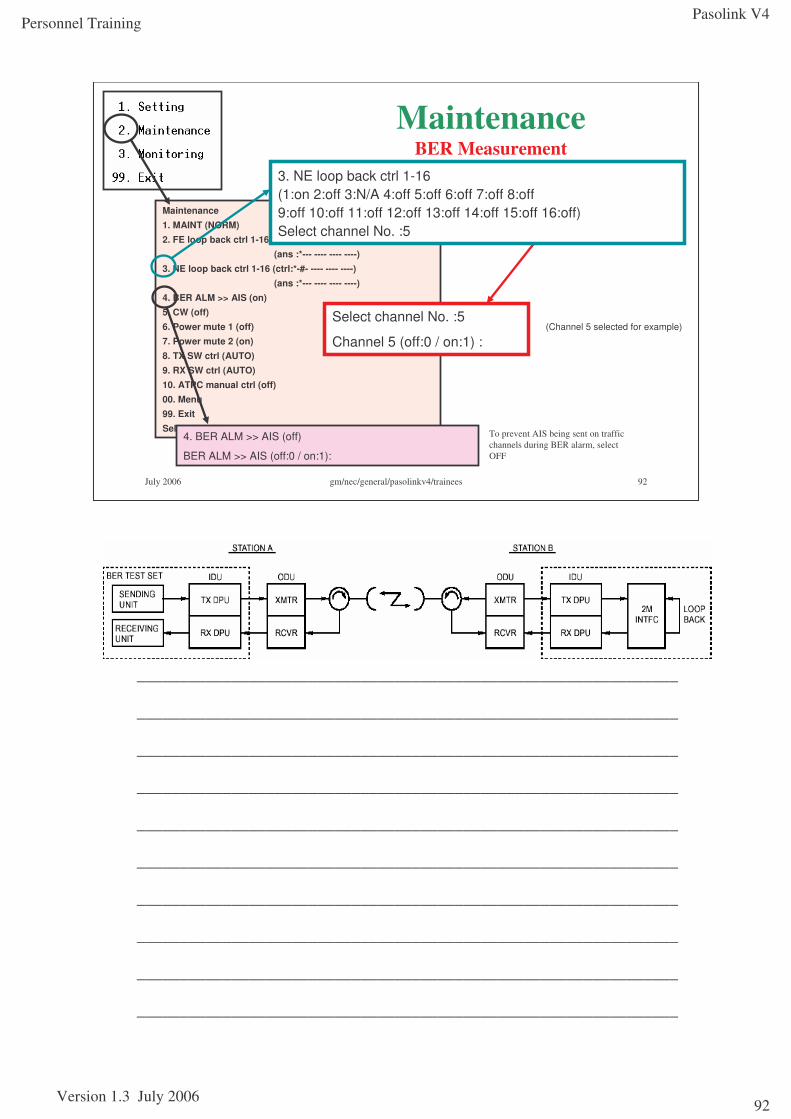
Pasolink V4
Version 1.3 July 2006
Personnel Training
92
July 2006 gm/nec/general/pasolinkv4/trainees 92
Maintenance1. MAINT (NORM)2. FE loop back ctrl 1-16 (ctrl:*Z#- ---- ---- ----)
(ans :*--- ---- ---- ----)3. NE loop back ctrl 1-16 (ctrl:*-#- ---- ---- ----)
(ans :*--- ---- ---- ----)4. BER ALM >> AIS (on)5. CW (off)6. Power mute 1 (off)7. Power mute 2 (on)8. TX SW ctrl (AUTO)9. RX SW ctrl (AUTO)10. ATPC manual ctrl (off)00. Menu99. ExitSelect item No.
MaintenanceBER Measurement
(Channel 5 selected for example)
4. BER ALM >> AIS (off)
BER ALM >> AIS (off:0 / on:1):
To prevent AIS being sent on traffic channels during BER alarm, select OFF
3. NE loop back ctrl 1-16(1:on 2:off 3:N/A 4:off 5:off 6:off 7:off 8:off9:off 10:off 11:off 12:off 13:off 14:off 15:off 16:off)Select channel No. :5
Select channel No. :5
Channel 5 (off:0 / on:1) :
_______________________________________________________________
_______________________________________________________________
_______________________________________________________________
_______________________________________________________________
_______________________________________________________________
_______________________________________________________________
_______________________________________________________________
_______________________________________________________________
_______________________________________________________________
_______________________________________________________________
Pasolink V4
Version 1.3 July 2006
Personnel Training
93
Maintenance1+1 IDU ReplacementThe 1+1 IDU consists of three units (No. 1 CH/SW UNIT/No. 2 CH). If any unit fails, replace only the unit that fails with a spare following the procedure described below.
Caution: When the SW UNIT (COMMON) unit is replaced, service is interrupted.Note: To replace the SW UNIT with a spare, remove both No. 1 and No. 2 CH units first.
Example: No. 1 CH UNIT (MD) REPLACEMENTRemoving1 Set OPR SEL No.1-AUTO-No. 2 switch on the SW UNIT to No. 2
2 Turn off the power switch on the No. 1 CH unit
3 Disconnect IF cable from the IF IN/OUT connector on the No. 1 unit
4 Loosen two screws on the No. 1 CH unit
5 To remove the unit, hold its handle then pull it forward
6 Reverse this procedure for insertion of the replacement
SW UNIT (COMMON) REPLACEMENTIn 1+1 system, when the SW UNIT is replaced, service is interrupted.Removing6 Carry out steps 2 to 5 for No. 1 CH unit
7 Repeat steps 2 to 5 for No. 2 CH unit
8 Disconnect coaxial and flat cables of the all connectors on the SW UNIT
9 Loosen two screws on the SW UNIT unit
10 To remove the unit, hold its handle then pull it forward
11 Reverse this procedure for insertion of the replacement
Setting ParametersPerform the setting according to commissioning procedures, only when you replaced a SW UNIT in the IDU with a spare.
The equipment is considered as fully warmed up after 30 minutes of being powered up
1+0 IDU ReplacementRemoving1 Turn off the power switch on the IDU
2 Disconnect IF cable from the IF IN/OUT connector on the IDU
3 Loosen two screws on the IDU
4 To remove the unit, hold its handle then pull it forward
5 Reverse this procedure for insertion of the replacement
6. The parameters for the radio will need to be set
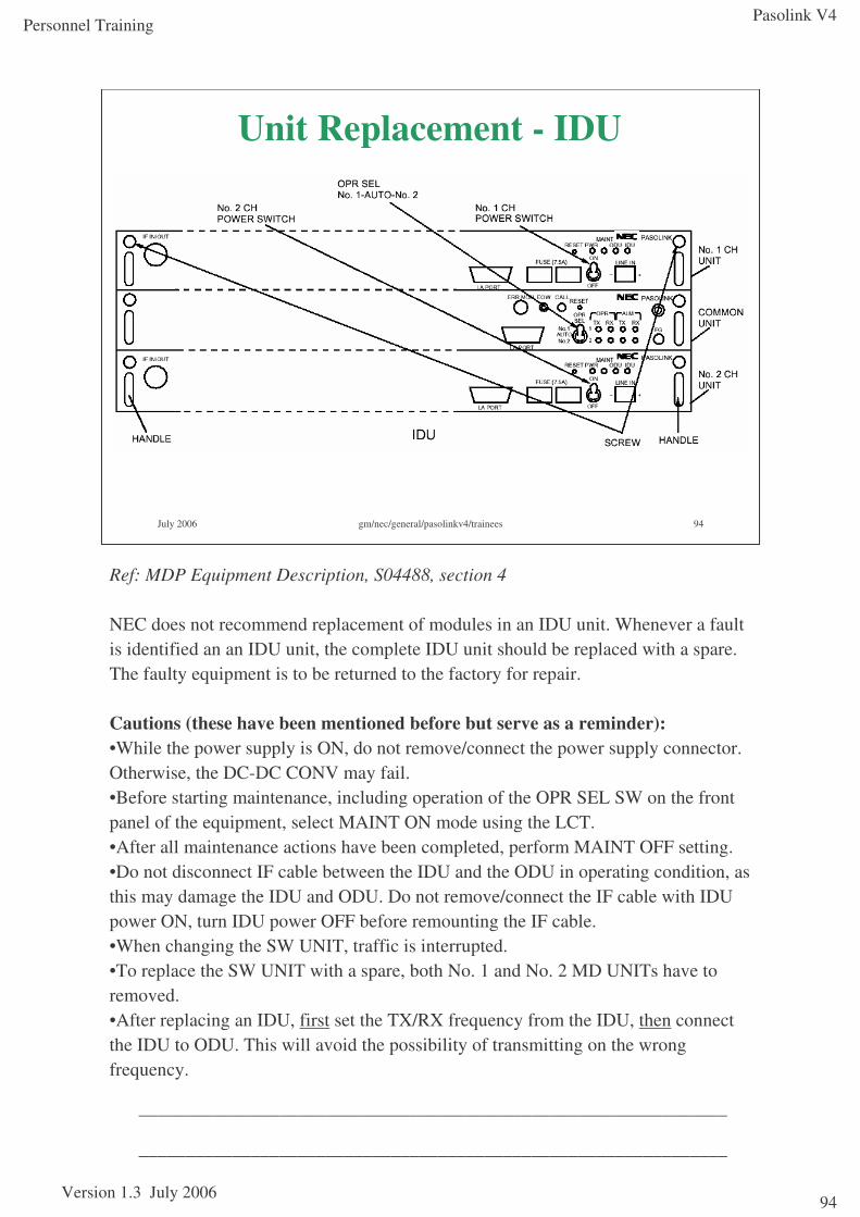
Pasolink V4
Version 1.3 July 2006
Personnel Training
94
July 2006 gm/nec/general/pasolinkv4/trainees 94
Unit Replacement - IDU
Ref: MDP Equipment Description, S04488, section 4
NEC does not recommend replacement of modules in an IDU unit. Whenever a fault is identified an an IDU unit, the complete IDU unit should be replaced with a spare. The faulty equipment is to be returned to the factory for repair.
Cautions (these have been mentioned before but serve as a reminder):•While the power supply is ON, do not remove/connect the power supply connector. Otherwise, the DC-DC CONV may fail.•Before starting maintenance, including operation of the OPR SEL SW on the front panel of the equipment, select MAINT ON mode using the LCT.•After all maintenance actions have been completed, perform MAINT OFF setting.•Do not disconnect IF cable between the IDU and the ODU in operating condition, as this may damage the IDU and ODU. Do not remove/connect the IF cable with IDU power ON, turn IDU power OFF before remounting the IF cable.•When changing the SW UNIT, traffic is interrupted.•To replace the SW UNIT with a spare, both No. 1 and No. 2 MD UNITs have to removed.•After replacing an IDU, first set the TX/RX frequency from the IDU, then connect the IDU to ODU. This will avoid the possibility of transmitting on the wrong frequency.
_______________________________________________________________
_______________________________________________________________
Pasolink V4
Version 1.3 July 2006
Personnel Training
95
Maintenance
Replacing ODUBefore replacing the ODU with a spare, ensure the spare operates in the correct sub-band and TX high/low as appropriate. Here are procedures for replacing the ODU with a spare after fault isolation:
Note: Procedures for No. 1 and No. 2 channels are identical.
Removing1. Turn off the POWER switch on the front panel of the IDU
2. Remove waterproofing and loosen tightening rings of the IF IN/OUT connector (N) on the ODU by turning them counter-clockwise,
3. Remove the waterproofing for waveguide connector type of ODU, and remove the waveguide from the RF IN/OUT by removing the four waveguide fixing screws using a screwdriver,
Note: Be careful not to damage the O-ring between the waveguide and ODU.
4. Remove earth cable
5. Loosen eight screws (M6) on the ODU
6. Remove the ODU
Notes: Be careful not to damage the O-ring between the waveguide and ODU.
7. Replace ODU with a spare, taking care when handling the coaxial/waveguide contact surface. Torque up the ODU screws: 4.5Nm or Direct or Remote Mount, 2.8Nm to Hybrid
8. Reconnect the earth cable
9. Reconnect the IF cable and waveguide, if relevant
10. Redo all waterproofing and cable/waveguide supports
11. Turn on the POWER switch on the front panel of the IDU
12. Confirm the parameters and functionality of the replacement ODU and perform a BER test if required.
The ODU is considered as fully warmed up 30 minutes after being power up
In 1+1 system, to avoid occurrence of bit errors due to microphonicproperties, when installing the standby ODU on to the antenna direct mounting HYB, protect the working ODU from mechanical knocks.
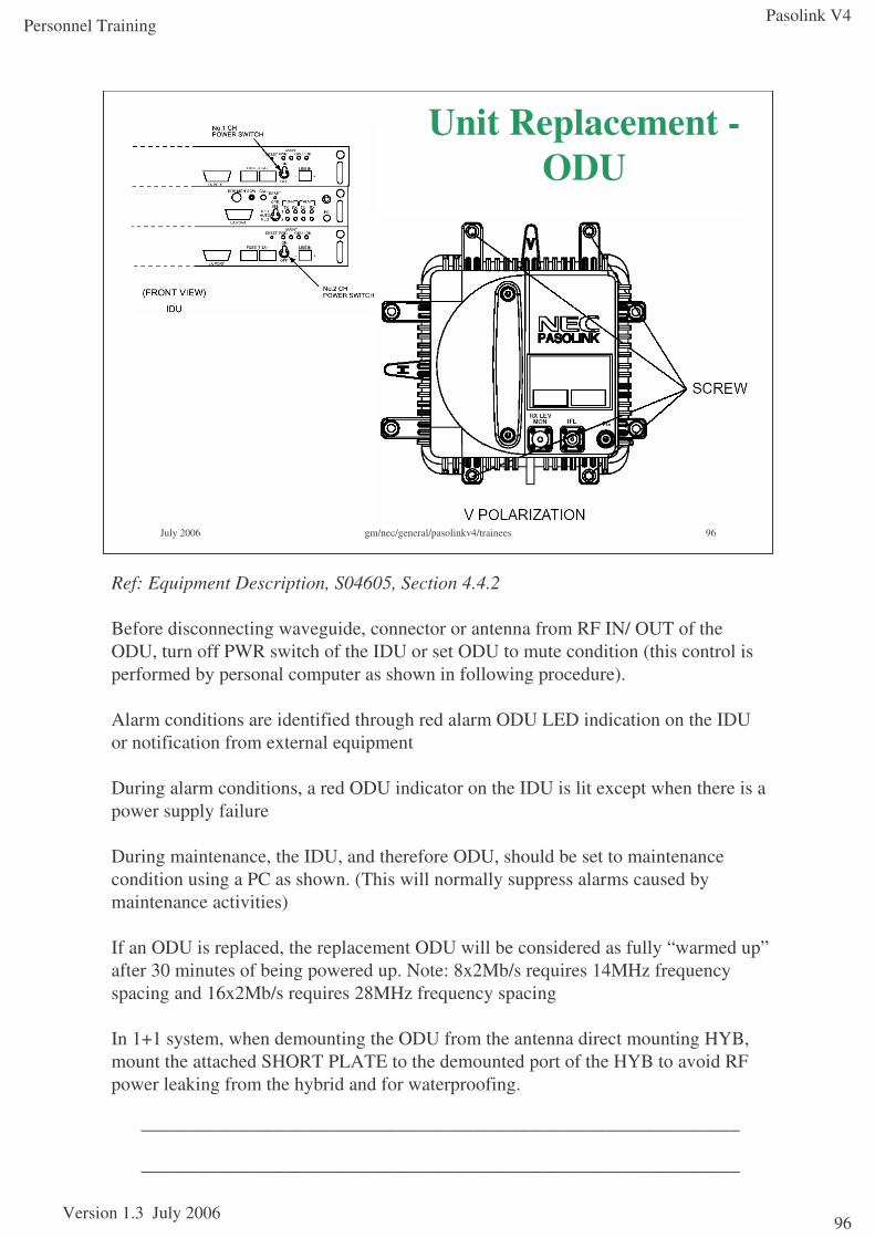
Pasolink V4
Version 1.3 July 2006
Personnel Training
96
July 2006 gm/nec/general/pasolinkv4/trainees 96
Unit Replacement -ODU
Ref: Equipment Description, S04605, Section 4.4.2
Before disconnecting waveguide, connector or antenna from RF IN/ OUT of the ODU, turn off PWR switch of the IDU or set ODU to mute condition (this control is performed by personal computer as shown in following procedure).
Alarm conditions are identified through red alarm ODU LED indication on the IDU or notification from external equipment
During alarm conditions, a red ODU indicator on the IDU is lit except when there is a power supply failure
During maintenance, the IDU, and therefore ODU, should be set to maintenance condition using a PC as shown. (This will normally suppress alarms caused by maintenance activities)
If an ODU is replaced, the replacement ODU will be considered as fully “warmed up”after 30 minutes of being powered up. Note: 8x2Mb/s requires 14MHz frequency spacing and 16x2Mb/s requires 28MHz frequency spacing
In 1+1 system, when demounting the ODU from the antenna direct mounting HYB, mount the attached SHORT PLATE to the demounted port of the HYB to avoid RF power leaking from the hybrid and for waterproofing.
_______________________________________________________________
_______________________________________________________________
Pasolink V4
Version 1.3 July 2006
Personnel Training
97
July 2006 gm/nec/general/pasolinkv4/trainees 97
Module 5Upgrades/Downgrades
Section objectivesThis section covers the following:
•Upgrading 1+0 system to 1+1
•Downgrading 1+1 system to 1+0
References:Pasolink V4 User (Instruction) Manual ROI-S0xxxx-051E
Abbreviations ROI-S04491-052EGeneral System Description ROI-S04604-052EMeasurement Procedure ROI-S04607-054ETRP Equipment Description ROI-S04605-054ERadio Frequency Assignment (n GHz) ROI-various-05xE
MDP Equipment Description ROI-S04488-058EInstallation and Initial Lineup ROI-S04606-054E
Pasolink V4 Sub-band Change Procedure
Pasolink V4 MTD (1+0 / 1+1) PL035-01
Pasolink V4
Version 1.3 July 2006
Personnel Training
98
1+0 mode in a 1+1 Chassis
It is possible to use a 1+1 radio in a 1+0 configuration. To disable the additional 1+1 features, select the 1+0 mode:
From the Settings Menu:
Enter [Control-A].
Select option 5.
Select 1+0: Enter [1][Return] for 1+0
Upgrading 1+0 systems (in 1+1 chassis) to 1+1 system
Use of the 1+1 chassis for all modes makes it possible to upgrade to 1+1 with minimal service interruption. The work order is as follows:
1. Lock the TX/RX path onto channel 1
2. Install lower Traffic Channel Unit
3. Install the second IF cable and terminate this on to the lower Traffic Channel Unit
3. If splitter/hybrid had previously been installed, install the second ODU. Otherwise a splitter/hybrid will need to be installed. Obviously, this involves traffic interruption and TX power level adjustments to take additional losses into consideration
4. Terminate the second IF cable on to the second ODU.
5. Enable the 1+1 features:
From the Settings Menu:
Enter [Control-A].
Select option 5.
Select 1+1. Enter [0][Return] for 1+1
Upgrading 1+0 systems (in 1+0 chassis) to 1+1 system (1+1 chassis)
This upgrade involves the removal of the existing IDU and ODU and following the procedure for installing a 1+1 system. The existing cabling (IF, DC power and tributary) should be used to minimise traffic interruption
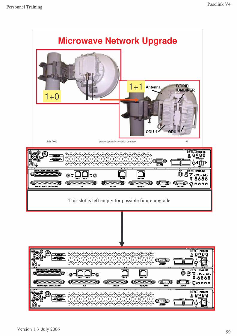
Pasolink V4
Version 1.3 July 2006
Personnel Training
99
July 2006 gm/nec/general/pasolinkv4/trainees 99
Microwave Network Upgrade
1+01+1
This slot is left empty for possible future upgrade

Pasolink V4
Version 1.3 July 2006
Personnel Training
100
This page has been left blank intentionally
Pasolink V4
Version 1.3 July 2006
Personnel Training
101
July 2006 gm/nec/general/pasolinkv4/trainees 101
Module 6Additional Parameter Options
Section objectivesThis section covers the following:
•Other optional parameter settings from the “hidden” menu
References:Pasolink V4 User (Instruction) Manual ROI-S0xxxx-051E
Abbreviations ROI-S04491-052EGeneral System Description ROI-S04604-052EMeasurement Procedure ROI-S04607-054ETRP Equipment Description ROI-S04605-054ERadio Frequency Assignment (15GHz) ROI-S04760-051ERadio Frequency Assignment (23GHz) ROI-S04759-052EMDP Equipment Description ROI-S04488-058EInstallation and Initial Lineup ROI-S04606-054E
Pasolink V4 Sub-band Change Procedure
Pasolink V4 MTD (1+0 / 1+1) PL035-01
Pasolink V4
Version 1.3 July 2006
Personnel Training
102
Other parameters can be changed from a hidden menu:To gain access to the hidden menu:
From the Settings Menu:
Enter [Control-A].
A list of options will be shown, according to whether the terminal is 1+0 or 1+1:
1. AIS SEND Report (report/not report)
Select whether to report AIS SEND alarms or status to PNMS
2. AIS RCVD Report (report:#### #### RRRR RRRR)
#: function not available (E1 channel used for LAN)
R: send report to PNMS for specified channel. (channel must be IN USE to select this)
N: do not send report PNMS for channel (channel must be IN USE to select this)
3. WS AIS RCVD report (report/not report)
Select whether to report Wayside AIS Received condition to PNMS
4. Setting clear
Resets IDU to factory defaults. Use only as last resort. No warnings are issued!
5. MD program download
For downloading firmware to the IDU MD. This requires a file and file location to be identified within the PC attached. PNMT is normally used for this activity.
6. ODU program download
For downloading firmware to the IDU MD. This requires a file and file location to be identified within the PC attached. PNMT is normally used for this activity.
7. MAINT on AIS activation condition (enable)
IDU automatically assumes MAINT state in event AIS BER = OFF is selected from Maintenance Menu.
8. ODU sub band
Option to re-specify ODU sub-band in event to filter change. This also sets the synthesiser to the correct operating sub-band.
9. LAN reset
Resets specified LAN port
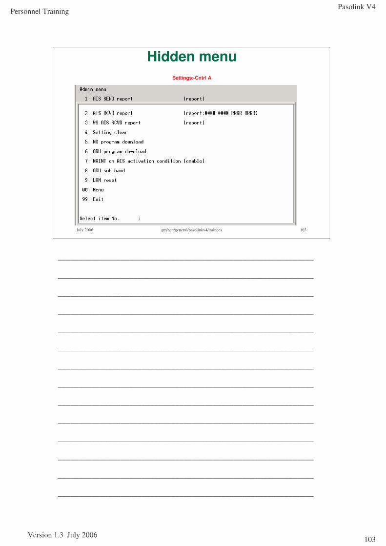
Pasolink V4
Version 1.3 July 2006
Personnel Training
103
July 2006 gm/nec/general/pasolinkv4/trainees 103
Hidden menu Settings>Cntrl A
_____________________________________________________________
_____________________________________________________________
_____________________________________________________________
_____________________________________________________________
_____________________________________________________________
_____________________________________________________________
_____________________________________________________________
_____________________________________________________________
_____________________________________________________________
_____________________________________________________________
_____________________________________________________________
_____________________________________________________________
_____________________________________________________________
_____________________________________________________________

Pasolink V4
Version 1.3 July 2006
Personnel Training
104
This page has been left blank intentionally and can be used for further notes
Pasolink V4
Version 1.3 July 2006
Personnel Training
105
July 2006 gm/nec/general/pasolinkv4/trainees 105
Module 7Appendices
Section objectivesThis section covers the following:
•Abbreviations
•Alarm items
•Typical microwave antenna parameters
References:Pasolink V4 User (Instruction) Manual ROI-S0xxxx-051E
Abbreviations ROI-S04491-052EGeneral System Description ROI-S04604-052EMeasurement Procedure ROI-S04607-054ETRP Equipment Description ROI-S04605-054ERadio Frequency Assignment (n GHz) ROI-various-05xE
MDP Equipment Description ROI-S04488-058EInstallation and Initial Lineup ROI-S04606-054E
Pasolink V4 Sub-band Change Procedure
Pasolink V4 MTD (1+0 / 1+1) PL035-01
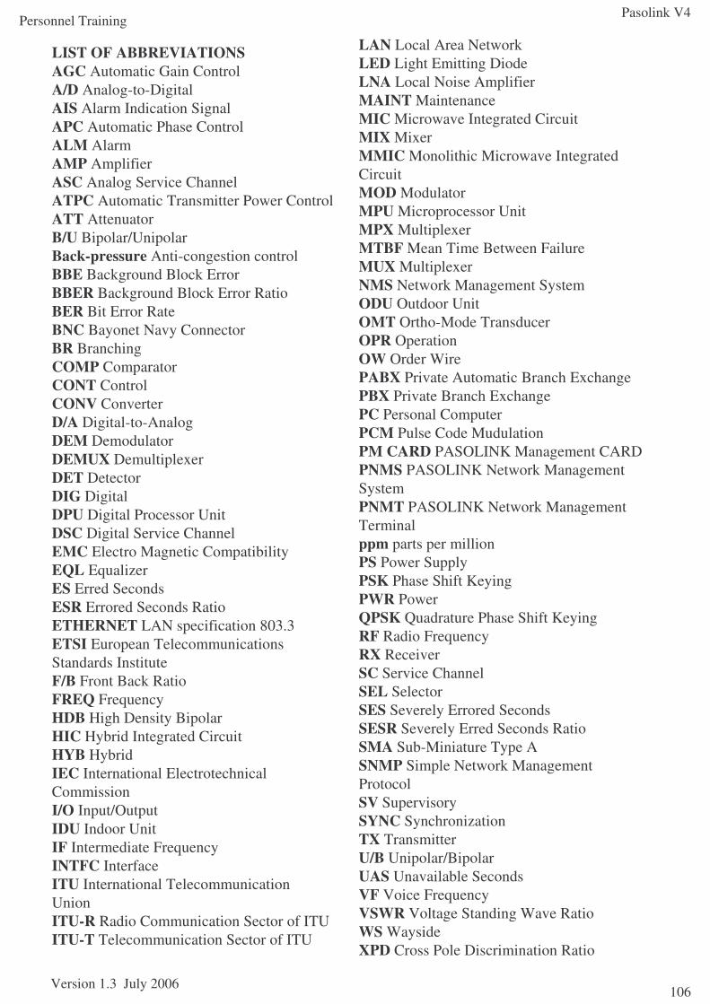
Pasolink V4
Version 1.3 July 2006
Personnel Training
106
LIST OF ABBREVIATIONSAGC Automatic Gain ControlA/D Analog-to-DigitalAIS Alarm Indication SignalAPC Automatic Phase ControlALM AlarmAMP AmplifierASC Analog Service ChannelATPC Automatic Transmitter Power ControlATT AttenuatorB/U Bipolar/UnipolarBack-pressure Anti-congestion controlBBE Background Block ErrorBBER Background Block Error RatioBER Bit Error RateBNC Bayonet Navy ConnectorBR BranchingCOMP ComparatorCONT ControlCONV ConverterD/A Digital-to-AnalogDEM DemodulatorDEMUX DemultiplexerDET DetectorDIG DigitalDPU Digital Processor UnitDSC Digital Service ChannelEMC Electro Magnetic CompatibilityEQL EqualizerES Erred SecondsESR Errored Seconds RatioETHERNET LAN specification 803.3ETSI European TelecommunicationsStandards InstituteF/B Front Back RatioFREQ FrequencyHDB High Density BipolarHIC Hybrid Integrated CircuitHYB HybridIEC International ElectrotechnicalCommissionI/O Input/OutputIDU Indoor UnitIF Intermediate FrequencyINTFC InterfaceITU International TelecommunicationUnionITU-R Radio Communication Sector of ITUITU-T Telecommunication Sector of ITU
LAN Local Area NetworkLED Light Emitting DiodeLNA Local Noise AmplifierMAINT MaintenanceMIC Microwave Integrated CircuitMIX MixerMMIC Monolithic Microwave IntegratedCircuitMOD ModulatorMPU Microprocessor UnitMPX MultiplexerMTBF Mean Time Between FailureMUX MultiplexerNMS Network Management SystemODU Outdoor UnitOMT Ortho-Mode TransducerOPR OperationOW Order WirePABX Private Automatic Branch ExchangePBX Private Branch ExchangePC Personal ComputerPCM Pulse Code MudulationPM CARD PASOLINK Management CARDPNMS PASOLINK Network ManagementSystemPNMT PASOLINK Network ManagementTerminalppm parts per millionPS Power SupplyPSK Phase Shift KeyingPWR PowerQPSK Quadrature Phase Shift KeyingRF Radio FrequencyRX ReceiverSC Service ChannelSEL SelectorSES Severely Errored SecondsSESR Severely Erred Seconds RatioSMA Sub-Miniature Type ASNMP Simple Network ManagementProtocolSV SupervisorySYNC SynchronizationTX TransmitterU/B Unipolar/BipolarUAS Unavailable SecondsVF Voice FrequencyVSWR Voltage Standing Wave RatioWS WaysideXPD Cross Pole Discrimination Ratio
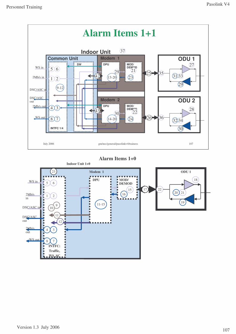
Pasolink V4
Version 1.3 July 2006
Personnel Training
107
July 2006 gm/nec/general/pasolinkv4/trainees 107
Alarm Items 1+1
ODU 1
ODU 2
Modem 1
Modem 2
Common UnitIndoor Unit
INTFC 1/4
SW
DPU
MOD/ DEMOD
DPU
MOD/ DEMOD
2Mb/s in 1 2
4 3
29
30
2513-20
2414-20
21
22
23
26
27
33
28
30
29
34
31
32
35
36
42
43
WS in
DSC/ASC in
WS out
DSC/ASC out
2Mb/s out
8 7
5 6
37
9-12
ODU 1Modem 1
Indoor Unit 1+0
MOD/ DEMOD
DPU
2Mb/s in
1 2
4 3
12
11
171516
23
18
21
19
2022
2Mb/s out
WS in
DSC/ASC in
WS out
DSC/ASC out
INTFC:Traffic, WS ,SC
5 6
8 7
Alarm Items 1+0
11-15910
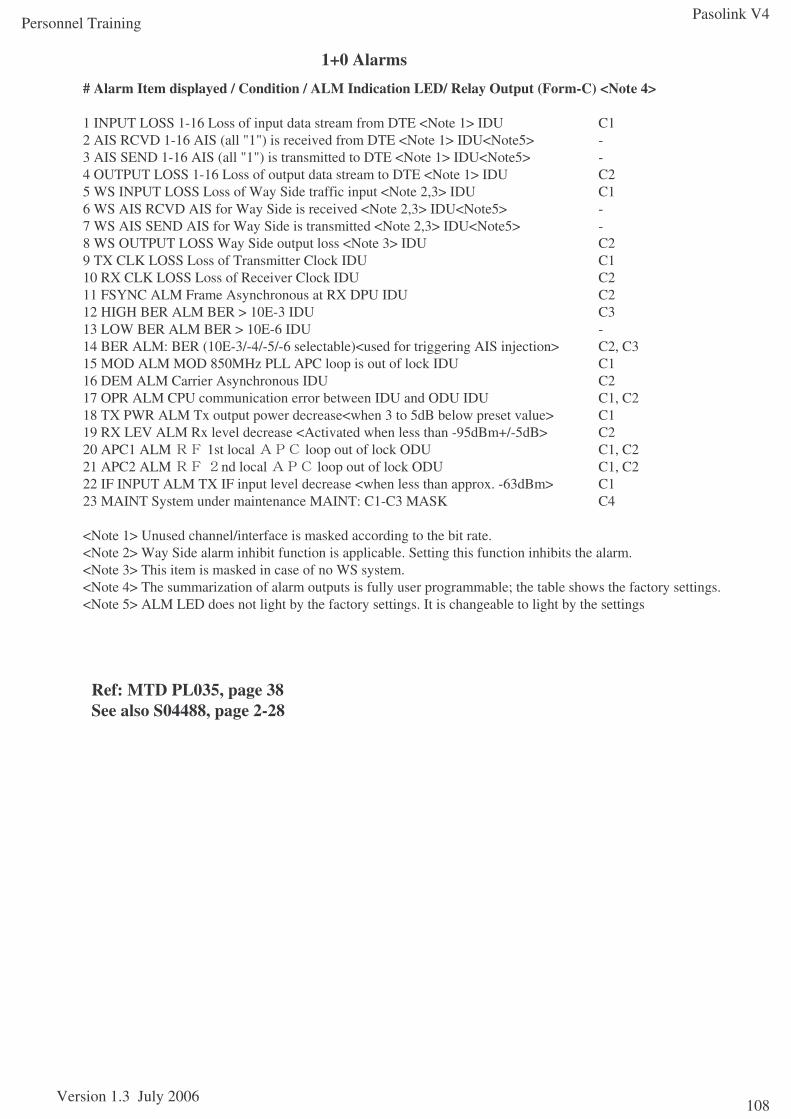
Pasolink V4
Version 1.3 July 2006
Personnel Training
108
1+0 Alarms
Ref: MTD PL035, page 38See also S04488, page 2-28
# Alarm Item displayed / Condition / ALM Indication LED/ Relay Output (Form-C) <Note 4>
1 INPUT LOSS 1-16 Loss of input data stream from DTE <Note 1> IDU C12 AIS RCVD 1-16 AIS (all "1") is received from DTE <Note 1> IDU<Note5> -3 AIS SEND 1-16 AIS (all "1") is transmitted to DTE <Note 1> IDU<Note5> -4 OUTPUT LOSS 1-16 Loss of output data stream to DTE <Note 1> IDU C25 WS INPUT LOSS Loss of Way Side traffic input <Note 2,3> IDU C16 WS AIS RCVD AIS for Way Side is received <Note 2,3> IDU<Note5> -7 WS AIS SEND AIS for Way Side is transmitted <Note 2,3> IDU<Note5> -8 WS OUTPUT LOSS Way Side output loss <Note 3> IDU C29 TX CLK LOSS Loss of Transmitter Clock IDU C110 RX CLK LOSS Loss of Receiver Clock IDU C211 FSYNC ALM Frame Asynchronous at RX DPU IDU C212 HIGH BER ALM BER > 10E-3 IDU C313 LOW BER ALM BER > 10E-6 IDU -14 BER ALM: BER (10E-3/-4/-5/-6 selectable)<used for triggering AIS injection> C2, C315 MOD ALM MOD 850MHz PLL APC loop is out of lock IDU C116 DEM ALM Carrier Asynchronous IDU C217 OPR ALM CPU communication error between IDU and ODU IDU C1, C218 TX PWR ALM Tx output power decrease<when 3 to 5dB below preset value> C119 RX LEV ALM Rx level decrease <Activated when less than -95dBm+/-5dB> C220 APC1 ALM 1st local loop out of lock ODU C1, C221 APC2 ALM nd local loop out of lock ODU C1, C222 IF INPUT ALM TX IF input level decrease <when less than approx. -63dBm> C123 MAINT System under maintenance MAINT: C1-C3 MASK C4
<Note 1> Unused channel/interface is masked according to the bit rate.<Note 2> Way Side alarm inhibit function is applicable. Setting this function inhibits the alarm.<Note 3> This item is masked in case of no WS system.<Note 4> The summarization of alarm outputs is fully user programmable; the table shows the factory settings.<Note 5> ALM LED does not light by the factory settings. It is changeable to light by the settings
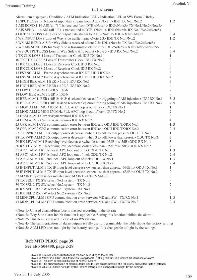
Pasolink V4
Version 1.3 July 2006
Personnel Training
109
1+1 Alarms
Ref: MTD PL035, page 39See also S04488, page 2-28
Alarm item displayed / Condition / ALM Indication LED / Indication LED at SW/ Form C Relay1 INPUT LOSS 1-16 Loss of input data stream from DTE <Note 1> IDU TX No.1/No.2 1, 22 AIS RCVD 1-16 AIS (all "1") is received from DTE <Note 1> IDU<Note5> TX No.1/No.2<Note5> -3 AIS SEND 1-16 AIS (all "1") is transmitted to DTE <Note 1> IDU<Note5> RX No.1/No.2<Note5> -4 OUTPUT LOSS 1-16 Loss of output data stream to DTE <Note 1> IDU RX No.1/No.2 3, 45 WS INPUT LOSS Loss of Way Side traffic input <Note 2,3> IDU TX No.1/No.2 1, 2 6 WS AIS RCVD AIS for Way Side is received <Note 2,3> IDU<Note5> TX No.1/No.2<Note5> -7 WS AIS SEND AIS for Way Side is transmitted <Note 2,3> IDU<Note5> RX No.1/No.2<Note5> -8 WS OUTPUT LOSS Loss of Way Side traffic output <Note 3> IDU RX No.1/No.2 3, 49 TX CLK LOSS 1 Loss of Transmitter Clock IDU TX No.1 110 TX CLK LOSS 2 Loss of Transmitter Clock IDU TX No.2 211 RX CLK LOSS 1 Loss of Receiver Clock IDU RX No.1 312 RX CLK LOSS 2 Loss of Receiver Clock IDU RX No.2 413 FSYNC ALM 1 Frame Asynchronous at RX DPU IDU RX No.1 314 FSYNC ALM 2 Frame Asynchronous at RX DPU IDU RX No.2 415 HIGH BER ALM 1 BER > 10E-3 IDU RX No.1 316 HIGH BER ALM 2 BER > 10E-3 IDU RX No.2 417 LOW BER ALM 1 BER > 10E-6 -18 LOW BER ALM 2 BER > 10E-6 -19 BER ALM 1: BER (10E-3/-4/-5/-6 selectable) <used for triggering of AIS injection> IDU RX No.1 3, 520 BER ALM 2: BER (10E-3/-4/-5/-6 selectable) <used for triggering of AIS injection> IDU RX No.2 4, 521 MOD ALM 1 MOD 850MHz PLL APC loop is out of lock IDU TX No.1 122 MOD ALM 2 MOD 850MHz PLL APC loop is out of lock IDU TX No.2 223 DEM ALM 1 Carrier asynchronous IDU RX No.1 324 DEM ALM 2 Carrier asynchronous IDU RX No.2 425 OPR ALM 1 CPU communication error between IDU and ODU IDU TX/RX No.1 1, 326 OPR ALM 2 CPU communication error between IDU and ODU IDU TX/RX No.2 2, 427 TX PWR ALM 1 TX output power decrease <when 3 to 5dB below preset.> ODU TX No.1 128 TX PWR ALM 2 TX output power decrease <when 3 to 5dB lower than preset.> ODU TX No.2 229 RX LEV ALM 1 Receiving level decrease <when less than -95dBm+/-5dB) ODU RX No.1 330 RX LEV ALM 2 Receiving level decrease <when less than -95dBm+/-5dB) ODU RX No.2 431 APC1 ALM 1 RF 1st local APC loop out of lock ODU TX No.1 1, 332 APC1 ALM 2 RF 1st local APC loop out of lock ODU TX No.2 2, 433 APC2 ALM 1 RF 2nd local APC loop out of lock ODU RX No.1 1, 334 APC2 ALM 2 RF 2nd local APC loop out of lock ODU RX No.2 2, 435 IF INPUT ALM 1 TX IF input level decrease <when less than approx. -63dBm> ODU TX No.1 136 IF INPUT ALM 2 TX IF input level decrease <when less than approx. -63dBm> ODU TX No.2 237 MAINT System under maintenance MAINT – C1-C5 MASK 638 TX SEL 1 TX SW select No.1 system - TX No.1 -39 TX SEL 2 TX SW select No.2 system - TX No.2 740 RX SEL 1 RX SW select No.1 system - RX No.1 -41 RX SEL 2 RX SW select No.2 system - RX No.2 842 MDP CPU ALM1 CPU communication error between MD and SW - TX/RX No.1 1, 343 MDP CPU ALM2 CPU communication error between MD and SW - TX/RX No.2 2, 4
<Note 1> Unused channel/interface is masked according to the bit rate.<Note 2> Way Side alarm inhibit function is applicable. Setting this function inhibits the alarm.<Note 3> This item is masked in case of no WS system.<Note 4> The summarization of alarm outputs is fully user programmable; the table shows the factory settings.<Note 5> ALM LED does not light by the factory settings. It is changeable to light by the settings.
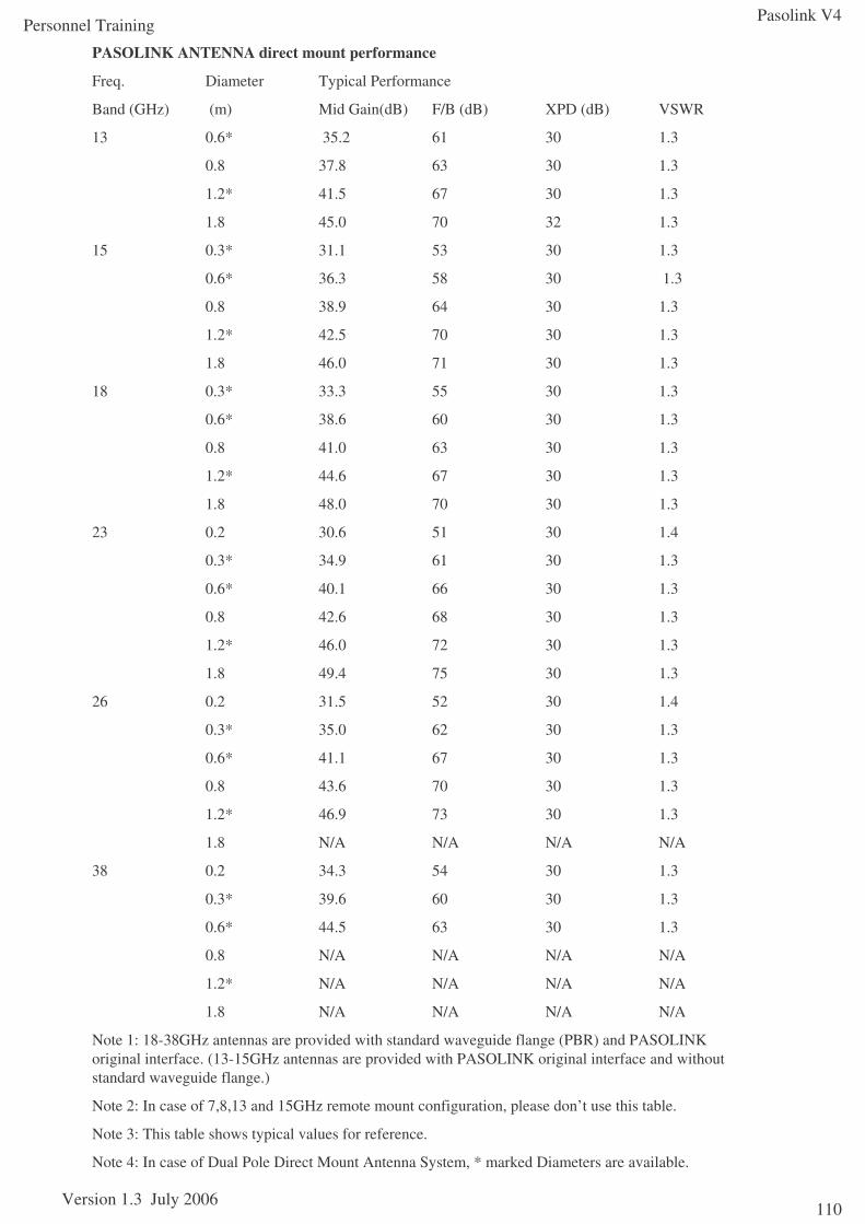
Pasolink V4
Version 1.3 July 2006
Personnel Training
110
PASOLINK ANTENNA direct mount performance
Freq. Diameter Typical Performance
Band (GHz) (m) Mid Gain(dB) F/B (dB) XPD (dB) VSWR
13 0.6* 35.2 61 30 1.3
0.8 37.8 63 30 1.3
1.2* 41.5 67 30 1.3
1.8 45.0 70 32 1.3
15 0.3* 31.1 53 30 1.3
0.6* 36.3 58 30 1.3
0.8 38.9 64 30 1.3
1.2* 42.5 70 30 1.3
1.8 46.0 71 30 1.3
18 0.3* 33.3 55 30 1.3
0.6* 38.6 60 30 1.3
0.8 41.0 63 30 1.3
1.2* 44.6 67 30 1.3
1.8 48.0 70 30 1.3
23 0.2 30.6 51 30 1.4
0.3* 34.9 61 30 1.3
0.6* 40.1 66 30 1.3
0.8 42.6 68 30 1.3
1.2* 46.0 72 30 1.3
1.8 49.4 75 30 1.3
26 0.2 31.5 52 30 1.4
0.3* 35.0 62 30 1.3
0.6* 41.1 67 30 1.3
0.8 43.6 70 30 1.3
1.2* 46.9 73 30 1.3
1.8 N/A N/A N/A N/A
38 0.2 34.3 54 30 1.3
0.3* 39.6 60 30 1.3
0.6* 44.5 63 30 1.3
0.8 N/A N/A N/A N/A
1.2* N/A N/A N/A N/A
1.8 N/A N/A N/A N/A
Note 1: 18-38GHz antennas are provided with standard waveguide flange (PBR) and PASOLINK original interface. (13-15GHz antennas are provided with PASOLINK original interface and without standard waveguide flange.)
Note 2: In case of 7,8,13 and 15GHz remote mount configuration, please don’t use this table.
Note 3: This table shows typical values for reference.
Note 4: In case of Dual Pole Direct Mount Antenna System, * marked Diameters are available.