Embed Size (px)
Citation preview
REV: 11.2.10 Lincoln Foodservice Products, LLC 1111 North Hadley Road Fort Wayne, Indiana 46804 Telephone: 260.459.8200 Fax: 888.790.8193 Technical Support: 800.678.9511 lincolnfp.com
PARTS & SERVICE MANUAL
Digital Countertop Series 2500
Digital Countertop Service Manual 2
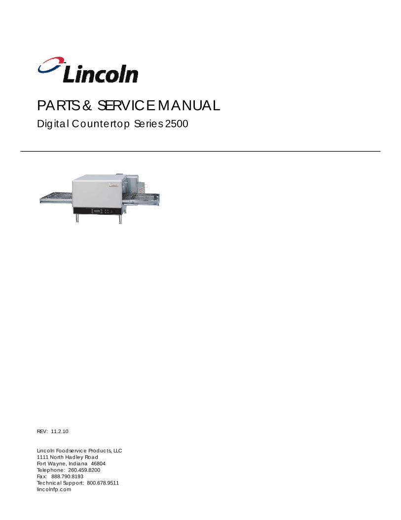
MODEL NUMBER KEY
EXAMPLE: 2501-000-U-0001620
25 01 - 0 00 - U - 00 0 1620
CODE LANGUAGE COUNTRY CODE LANGUAGE COUNTRY 0 English Dom. & Int. Default N Finnish Finland B French France/Luxembourg O Restricted --- C German Germany P Norwegian Norway D Italian Italy Q English Japan E Spanish Spain R Swedish Sweden F English UK/India/Africa/Hungary S English Australia G Spanish Mexico/Latin America T Mandarin China H Portuguese Portugal U Restricted --- I Not Used --- V English Pacific Rim/Korea J Danish Denmark W English Middle East
K Dutch & French Belgium X Not Used ---
L Dutch Netherlands Y Not Used --- M Greek Greece Z Not Used ---
AGENCY CODE TABLE
CODE AGENCY N No Agency E CE & RoHS compliance combined U US & Canada compliance only A Advantage style oven to be phased-out B Australia AGA
Finger Setup
Agency Code (i.e. CE & RoHS combined)
Custom Configuration Code (i.e. General Market Version)
Language Code
Indicates voltage (i.e. 208V, 1 phase, 60 Hz)
Model (i.e. Digital Countertop)
Platform Size
Digital Countertop Service Manual 3
Do not work around conveyor belt with long hair, loose clothing, or dangling jewelry. Getting caught in the conveyor belt could result in serious injury! !
WARNING:
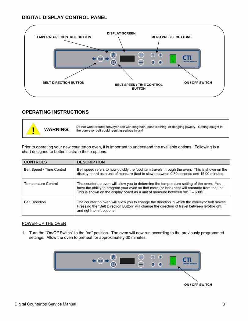
DIGITAL DISPLAY CONTROL PANEL OPERATING INSTRUCTIONS Prior to operating your new countertop oven, it is important to understand the available options. Following is a chart designed to better illustrate these options. CONTROLS DESCRIPTION Belt Speed / Time Control
Belt speed refers to how quickly the food item travels through the oven. This is shown on the display board as a unit of measure (fast to slow) between 0:30 seconds and 15:00 minutes.
Temperature Control
The countertop oven will allow you to determine the temperature setting of the oven. You have the ability to program your oven so that more (or less) heat will emanate from the unit. This is shown on the display board as a unit of measure between 90°F – 600°F.
Belt Direction
The countertop oven will allow you to change the direction in which the conveyor belt moves. Pressing the “Belt Direction Button” will change the direction of travel between left-to-right and right-to-left options.
POWER-UP THE OVEN 1. Turn the “On/Off Switch” to the “on” position. The oven will now run according to the previously programmed
settings. Allow the oven to preheat for approximately 30 minutes.
TEMPERATURE CONTROL BUTTON DISPLAY SCREEN
MENU PRESET BUTTONS
BELT DIRECTION BUTTON BELT SPEED / TIME CONTROL BUTTON
ON / OFF SWITCH
ON / OFF SWITCH
Digital Countertop Service Manual 4
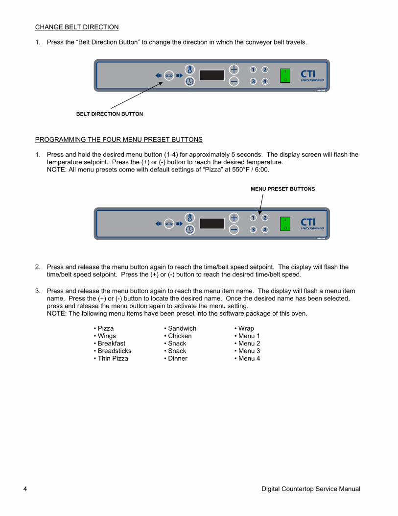
CHANGE BELT DIRECTION 1. Press the “Belt Direction Button” to change the direction in which the conveyor belt travels. PROGRAMMING THE FOUR MENU PRESET BUTTONS 1. Press and hold the desired menu button (1-4) for approximately 5 seconds. The display screen will flash the
temperature setpoint. Press the (+) or (-) button to reach the desired temperature. NOTE: All menu presets come with default settings of “Pizza” at 550°F / 6:00.
2. Press and release the menu button again to reach the time/belt speed setpoint. The display will flash the time/belt speed setpoint. Press the (+) or (-) button to reach the desired time/belt speed.
3. Press and release the menu button again to reach the menu item name. The display will flash a menu item name. Press the (+) or (-) button to locate the desired name. Once the desired name has been selected, press and release the menu button again to activate the menu setting. NOTE: The following menu items have been preset into the software package of this oven.
• Pizza • Sandwich • Wrap • Wings • Chicken • Menu 1 • Breakfast • Snack • Menu 2 • Breadsticks • Snack • Menu 3 • Thin Pizza • Dinner • Menu 4
BELT DIRECTION BUTTON
MENU PRESET BUTTONS
Digital Countertop Service Manual 5
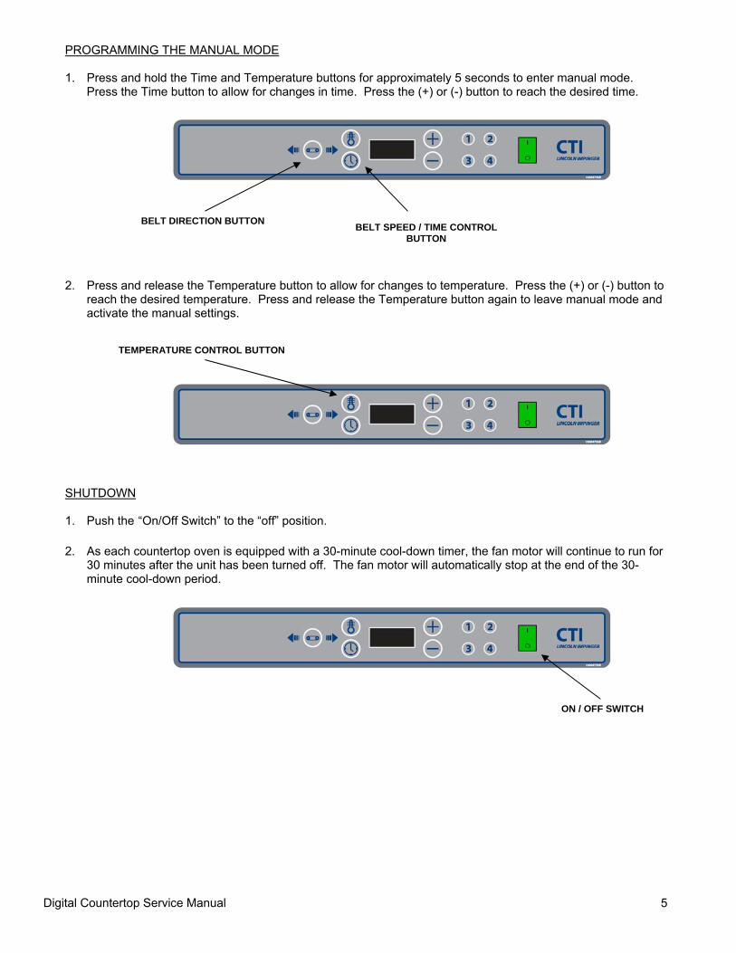
PROGRAMMING THE MANUAL MODE 1. Press and hold the Time and Temperature buttons for approximately 5 seconds to enter manual mode.
Press the Time button to allow for changes in time. Press the (+) or (-) button to reach the desired time.
2. Press and release the Temperature button to allow for changes to temperature. Press the (+) or (-) button to reach the desired temperature. Press and release the Temperature button again to leave manual mode and activate the manual settings.
SHUTDOWN 1. Push the “On/Off Switch” to the “off” position.
2. As each countertop oven is equipped with a 30-minute cool-down timer, the fan motor will continue to run for
30 minutes after the unit has been turned off. The fan motor will automatically stop at the end of the 30-minute cool-down period.
BELT DIRECTION BUTTON BELT SPEED / TIME CONTROL BUTTON
TEMPERATURE CONTROL BUTTON
ON / OFF SWITCH
Digital Countertop Service Manual 6
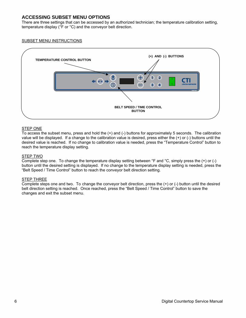
ACCESSING SUBSET MENU OPTIONS There are three settings that can be accessed by an authorized technician; the temperature calibration setting, temperature display (°F or °C) and the conveyor belt direction. SUBSET MENU INSTRUCTIONS STEP ONE To access the subset menu, press and hold the (+) and (-) buttons for approximately 5 seconds. The calibration value will be displayed. If a change to the calibration value is desired, press either the (+) or (-) buttons until the desired value is reached. If no change to calibration value is needed, press the “Temperature Control” button to reach the temperature display setting. STEP TWO Complete step one. To change the temperature display setting between °F and °C, simply press the (+) or (-) button until the desired setting is displayed. If no change to the temperature display setting is needed, press the “Belt Speed / Time Control” button to reach the conveyor belt direction setting. STEP THREE Complete steps one and two. To change the conveyor belt direction, press the (+) or (-) button until the desired belt direction setting is reached. Once reached, press the “Belt Speed / Time Control” button to save the changes and exit the subset menu.
TEMPERATURE CONTROL BUTTON (+) AND (-) BUTTONS
BELT SPEED / TIME CONTROL BUTTON
Digital Countertop Service Manual 7
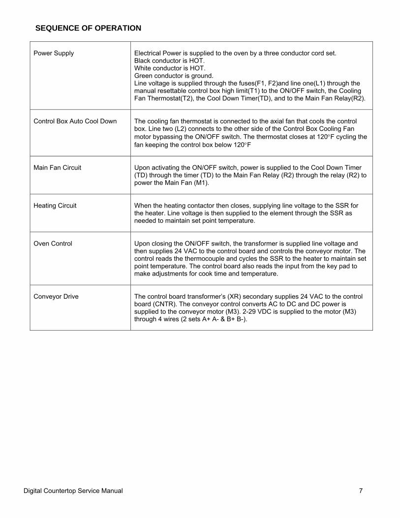
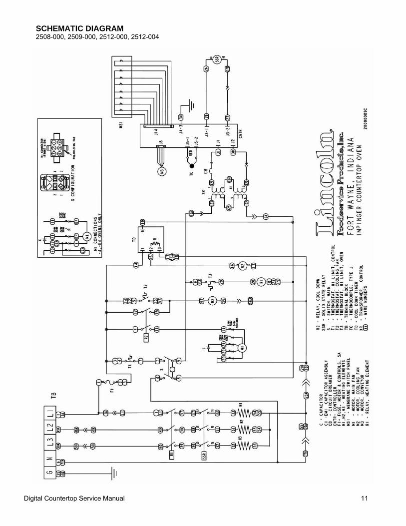
SEQUENCE OF OPERATION
Power Supply
Electrical Power is supplied to the oven by a three conductor cord set. Black conductor is HOT. White conductor is HOT. Green conductor is ground. Line voltage is supplied through the fuses(F1, F2)and line one(L1) through the manual resettable control box high limit(T1) to the ON/OFF switch, the Cooling Fan Thermostat(T2), the Cool Down Timer(TD), and to the Main Fan Relay(R2).
Control Box Auto Cool Down
The cooling fan thermostat is connected to the axial fan that cools the control box. Line two (L2) connects to the other side of the Control Box Cooling Fan motor bypassing the ON/OFF switch. The thermostat closes at 120°F cycling the fan keeping the control box below 120°F
Main Fan Circuit
Upon activating the ON/OFF switch, power is supplied to the Cool Down Timer (TD) through the timer (TD) to the Main Fan Relay (R2) through the relay (R2) to power the Main Fan (M1).
Heating Circuit
When the heating contactor then closes, supplying line voltage to the SSR for the heater. Line voltage is then supplied to the element through the SSR as needed to maintain set point temperature.
Oven Control
Upon closing the ON/OFF switch, the transformer is supplied line voltage and then supplies 24 VAC to the control board and controls the conveyor motor. The control reads the thermocouple and cycles the SSR to the heater to maintain set point temperature. The control board also reads the input from the key pad to make adjustments for cook time and temperature.
Conveyor Drive
The control board transformer’s (XR) secondary supplies 24 VAC to the control board (CNTR). The conveyor control converts AC to DC and DC power is supplied to the conveyor motor (M3). 2-29 VDC is supplied to the motor (M3) through 4 wires (2 sets A+ A- & B+ B-).
Digital Countertop Service Manual 8
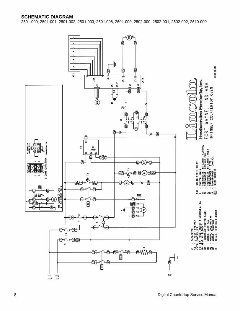
SCHEMATIC DIAGRAM 2501-000, 2501-001, 2501-002, 2501-003, 2501-008, 2501-009, 2502-000, 2502-001, 2502-002, 2510-000
Digital Countertop Service Manual 9
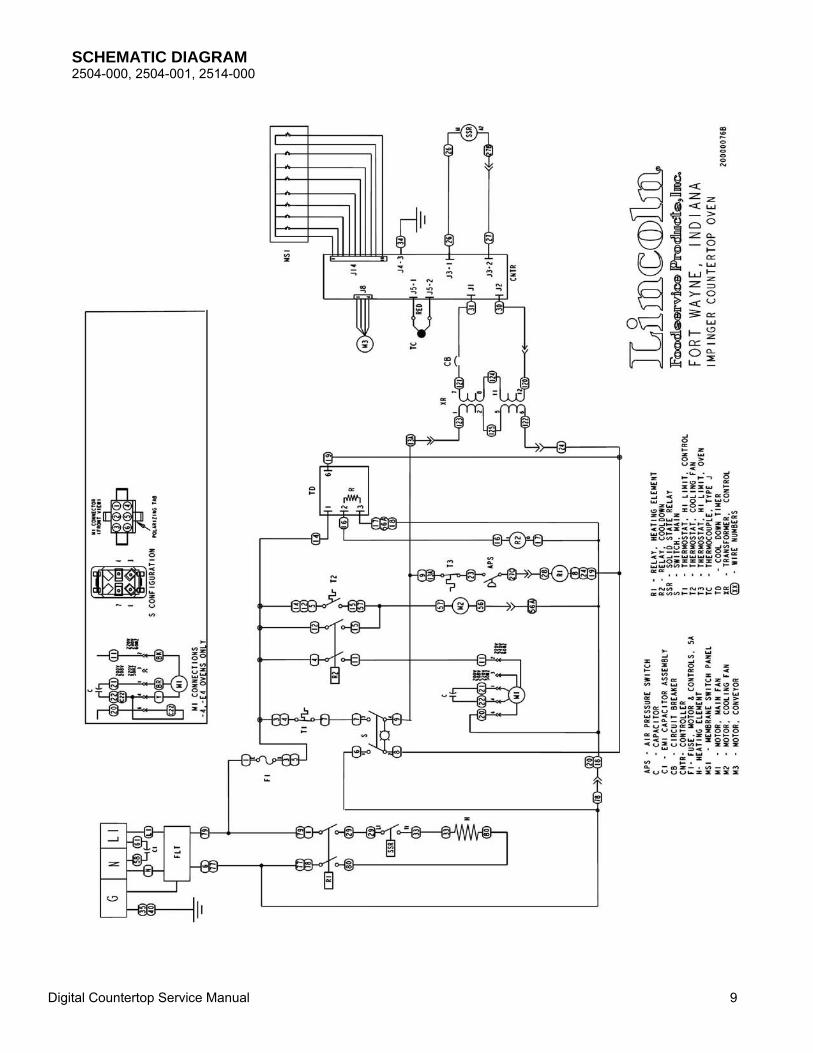
SCHEMATIC DIAGRAM 2504-000, 2504-001, 2514-000
Digital Countertop Service Manual 10
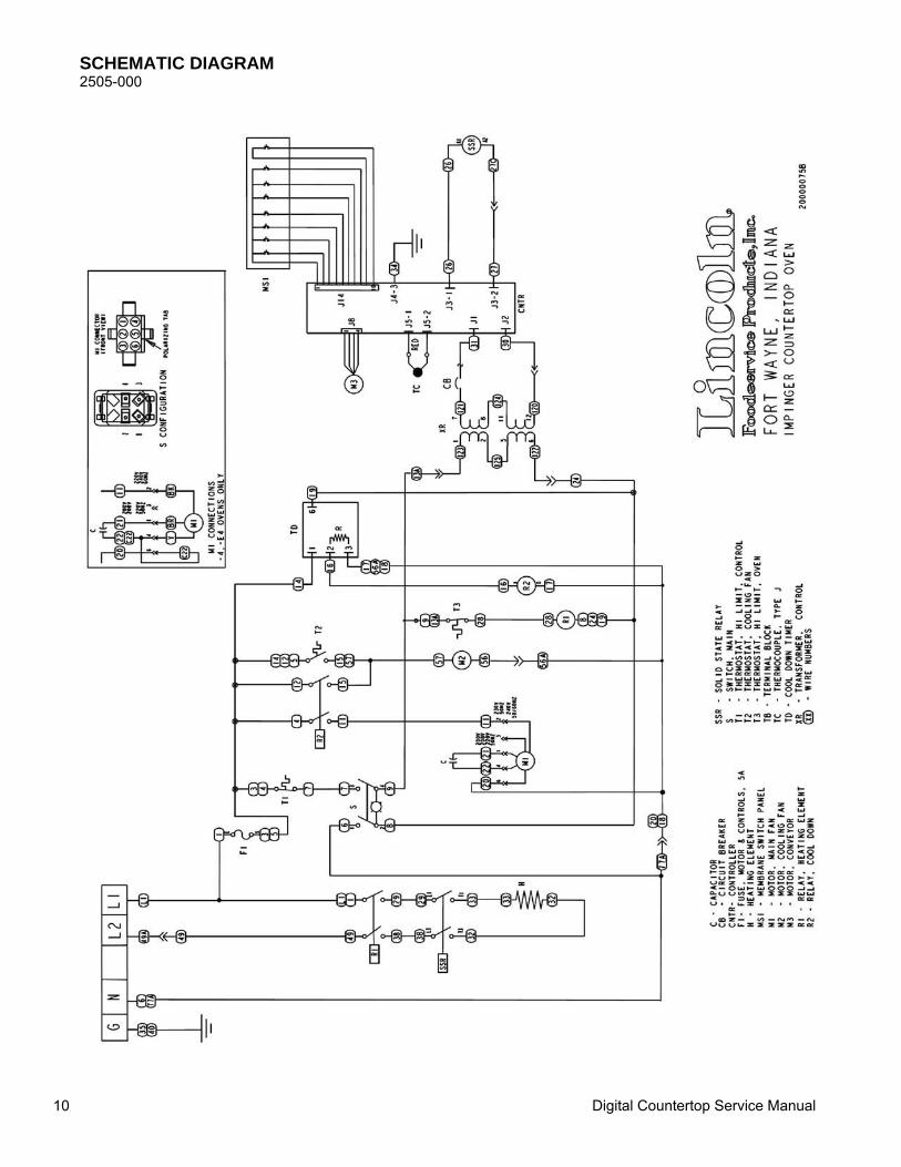
SCHEMATIC DIAGRAM 2505-000
Digital Countertop Service Manual 11
SCHEMATIC DIAGRAM 2508-000, 2509-000, 2512-000, 2512-004
Digital Countertop Service Manual 12
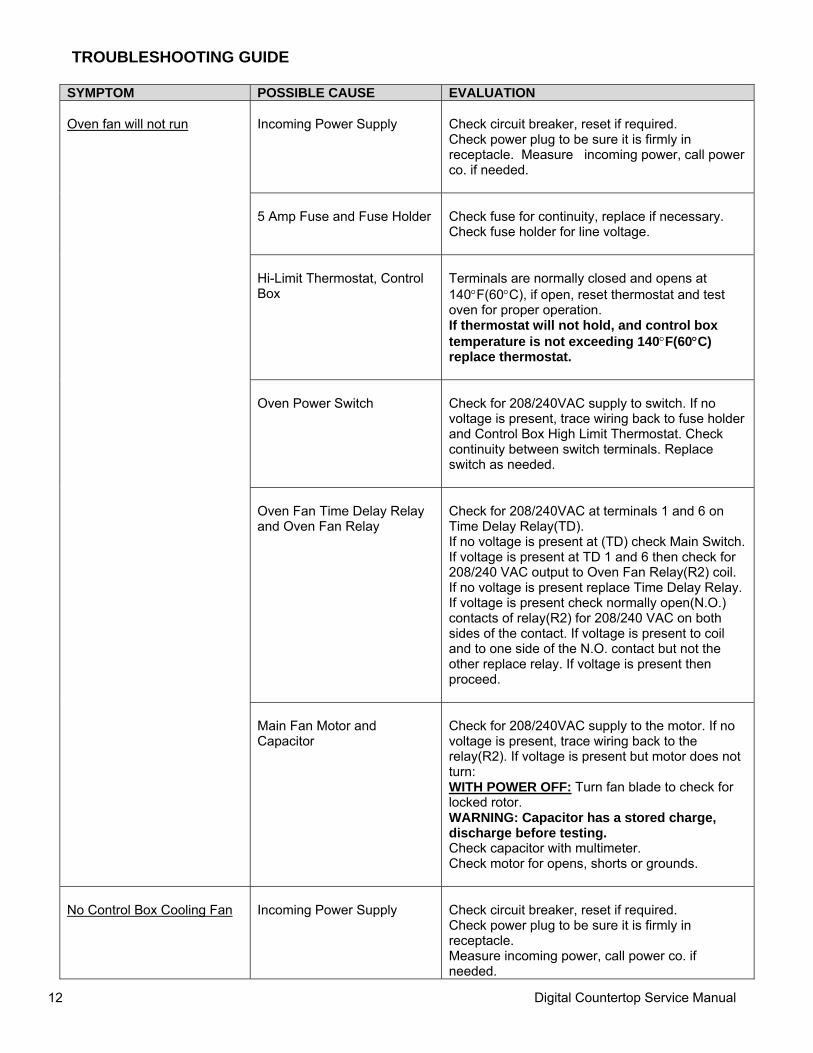
TROUBLESHOOTING GUIDE
SYMPTOM POSSIBLE CAUSE EVALUATION Oven fan will not run
Incoming Power Supply
Check circuit breaker, reset if required. Check power plug to be sure it is firmly in receptacle. Measure incoming power, call power co. if needed.
5 Amp Fuse and Fuse Holder
Check fuse for continuity, replace if necessary. Check fuse holder for line voltage.
Hi-Limit Thermostat, Control Box
Terminals are normally closed and opens at 140°F(60°C), if open, reset thermostat and test oven for proper operation. If thermostat will not hold, and control box temperature is not exceeding 140°F(60°C) replace thermostat.
Oven Power Switch
Check for 208/240VAC supply to switch. If no voltage is present, trace wiring back to fuse holder and Control Box High Limit Thermostat. Check continuity between switch terminals. Replace switch as needed.
Oven Fan Time Delay Relay and Oven Fan Relay
Check for 208/240VAC at terminals 1 and 6 on Time Delay Relay(TD). If no voltage is present at (TD) check Main Switch. If voltage is present at TD 1 and 6 then check for 208/240 VAC output to Oven Fan Relay(R2) coil. If no voltage is present replace Time Delay Relay. If voltage is present check normally open(N.O.) contacts of relay(R2) for 208/240 VAC on both sides of the contact. If voltage is present to coil and to one side of the N.O. contact but not the other replace relay. If voltage is present then proceed.
Main Fan Motor and Capacitor
Check for 208/240VAC supply to the motor. If no voltage is present, trace wiring back to the relay(R2). If voltage is present but motor does not turn: WITH POWER OFF: Turn fan blade to check for locked rotor. WARNING: Capacitor has a stored charge, discharge before testing. Check capacitor with multimeter. Check motor for opens, shorts or grounds.
No Control Box Cooling Fan
Incoming Power Supply
Check circuit breaker, reset if required. Check power plug to be sure it is firmly in receptacle. Measure incoming power, call power co. if needed.
Digital Countertop Service Manual 13
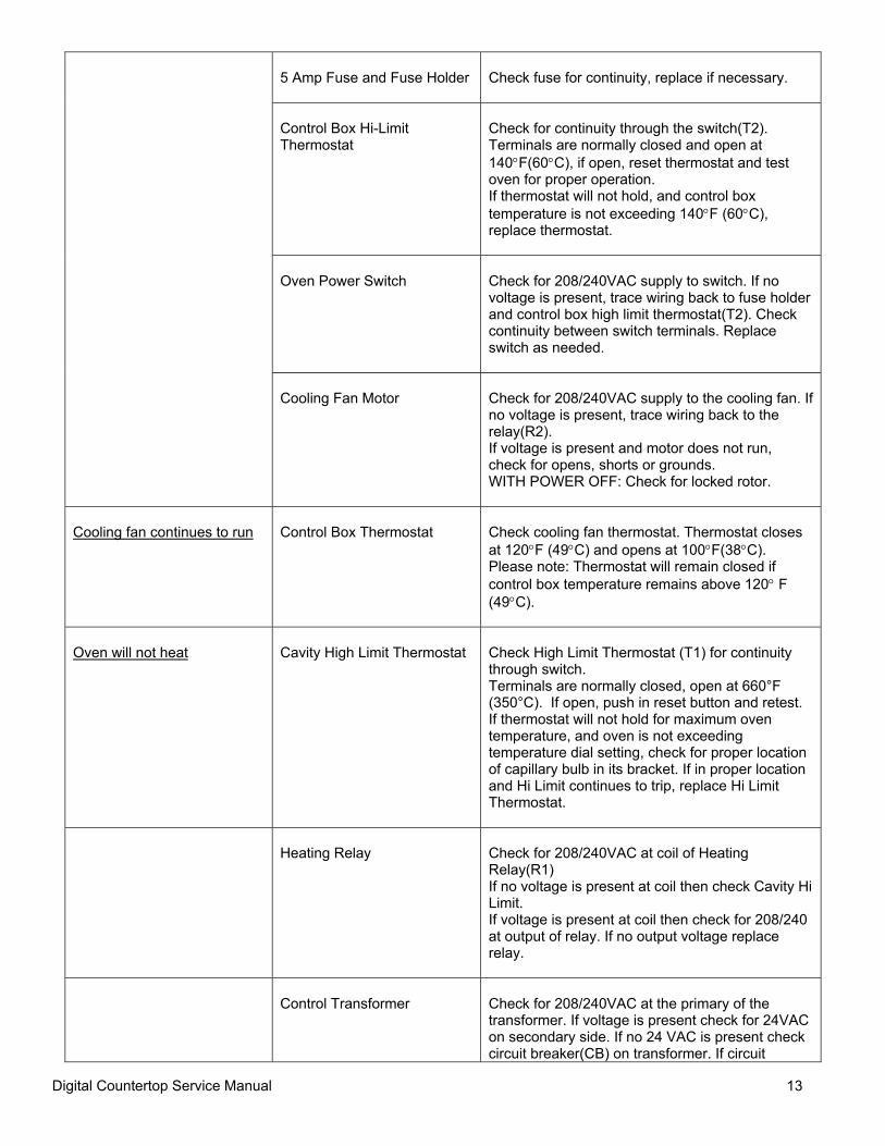
5 Amp Fuse and Fuse Holder
Check fuse for continuity, replace if necessary.
Control Box Hi-Limit Thermostat
Check for continuity through the switch(T2). Terminals are normally closed and open at 140°F(60°C), if open, reset thermostat and test oven for proper operation. If thermostat will not hold, and control box temperature is not exceeding 140°F (60°C), replace thermostat.
Oven Power Switch
Check for 208/240VAC supply to switch. If no voltage is present, trace wiring back to fuse holder and control box high limit thermostat(T2). Check continuity between switch terminals. Replace switch as needed.
Cooling Fan Motor
Check for 208/240VAC supply to the cooling fan. If no voltage is present, trace wiring back to the relay(R2). If voltage is present and motor does not run, check for opens, shorts or grounds. WITH POWER OFF: Check for locked rotor.
Cooling fan continues to run
Control Box Thermostat
Check cooling fan thermostat. Thermostat closes at 120°F (49°C) and opens at 100°F(38°C). Please note: Thermostat will remain closed if control box temperature remains above 120° F (49°C).
Oven will not heat
Cavity High Limit Thermostat
Check High Limit Thermostat (T1) for continuity through switch. Terminals are normally closed, open at 660°F (350°C). If open, push in reset button and retest. If thermostat will not hold for maximum oven temperature, and oven is not exceeding temperature dial setting, check for proper location of capillary bulb in its bracket. If in proper location and Hi Limit continues to trip, replace Hi Limit Thermostat.
Heating Relay
Check for 208/240VAC at coil of Heating Relay(R1) If no voltage is present at coil then check Cavity Hi Limit. If voltage is present at coil then check for 208/240 at output of relay. If no output voltage replace relay.
Control Transformer
Check for 208/240VAC at the primary of the transformer. If voltage is present check for 24VAC on secondary side. If no 24 VAC is present check circuit breaker(CB) on transformer. If circuit
Digital Countertop Service Manual 14
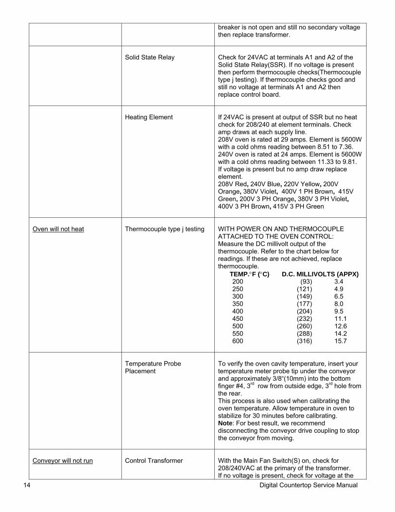
breaker is not open and still no secondary voltage then replace transformer.
Solid State Relay
Check for 24VAC at terminals A1 and A2 of the Solid State Relay(SSR). If no voltage is present then perform thermocouple checks(Thermocouple type j testing). If thermocouple checks good and still no voltage at terminals A1 and A2 then replace control board.
Heating Element
If 24VAC is present at output of SSR but no heat check for 208/240 at element terminals. Check amp draws at each supply line. 208V oven is rated at 29 amps. Element is 5600W with a cold ohms reading between 8.51 to 7.36. 240V oven is rated at 24 amps. Element is 5600W with a cold ohms reading between 11.33 to 9.81. If voltage is present but no amp draw replace element. 208V Red, 240V Blue, 220V Yellow, 200V Orange, 380V Violet, 400V 1 PH Brown, 415V Green, 200V 3 PH Orange, 380V 3 PH Violet, 400V 3 PH Brown, 415V 3 PH Green
Oven will not heat
Thermocouple type j testing
WITH POWER ON AND THERMOCOUPLE ATTACHED TO THE OVEN CONTROL: Measure the DC millivolt output of the thermocouple. Refer to the chart below for readings. If these are not achieved, replace thermocouple.
TEMP.°F (°C) D.C. MILLIVOLTS (APPX) 200 (93) 3.4 250 (121) 4.9 300 (149) 6.5 350 (177) 8.0 400 (204) 9.5 450 (232) 11.1 500 (260) 12.6 550 (288) 14.2 600 (316) 15.7
Temperature Probe Placement
To verify the oven cavity temperature, insert your temperature meter probe tip under the conveyor and approximately 3/8“(10mm) into the bottom finger #4, 3rd row from outside edge, 3rd hole from the rear. This process is also used when calibrating the oven temperature. Allow temperature in oven to stabilize for 30 minutes before calibrating. Note: For best result, we recommend disconnecting the conveyor drive coupling to stop the conveyor from moving.
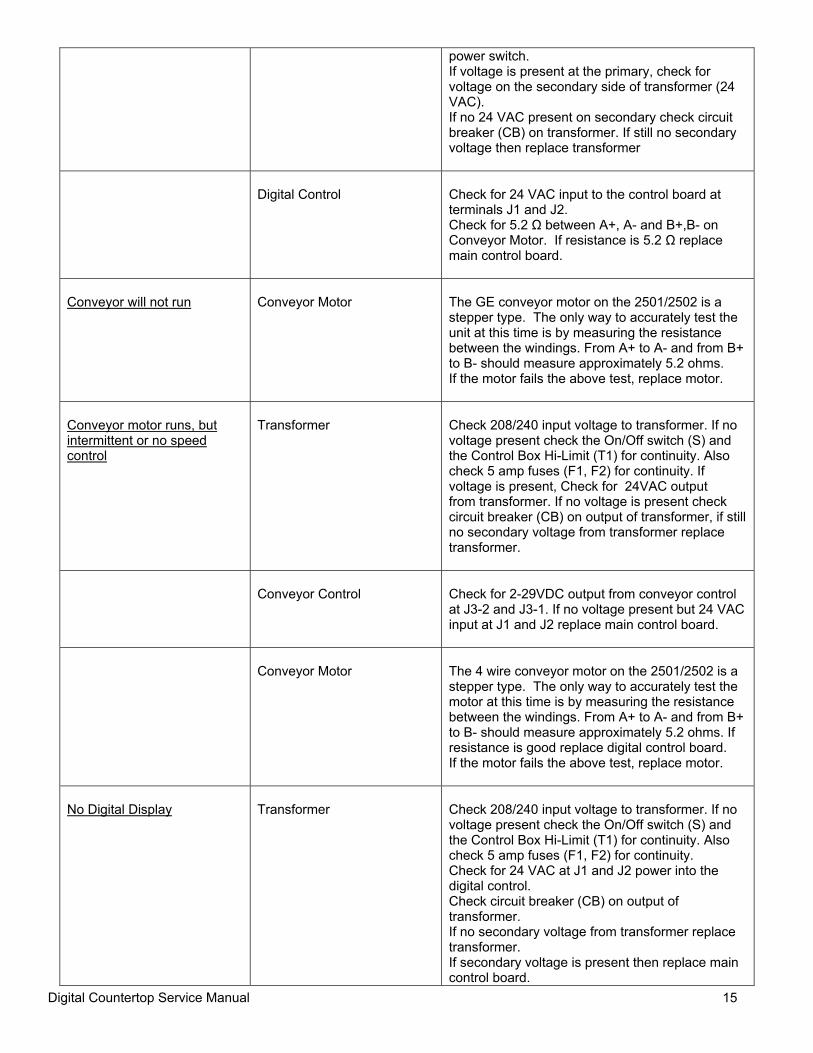
Conveyor will not run
Control Transformer
With the Main Fan Switch(S) on, check for 208/240VAC at the primary of the transformer. If no voltage is present, check for voltage at the
Digital Countertop Service Manual 15
power switch. If voltage is present at the primary, check for voltage on the secondary side of transformer (24 VAC). If no 24 VAC present on secondary check circuit breaker (CB) on transformer. If still no secondary voltage then replace transformer
Digital Control
Check for 24 VAC input to the control board at terminals J1 and J2. Check for 5.2 Ω between A+, A- and B+,B- on Conveyor Motor. If resistance is 5.2 Ω replace main control board.
Conveyor will not run
Conveyor Motor
The GE conveyor motor on the 2501/2502 is a stepper type. The only way to accurately test the unit at this time is by measuring the resistance between the windings. From A+ to A- and from B+ to B- should measure approximately 5.2 ohms. If the motor fails the above test, replace motor.
Conveyor motor runs, but intermittent or no speed control
Transformer
Check 208/240 input voltage to transformer. If no voltage present check the On/Off switch (S) and the Control Box Hi-Limit (T1) for continuity. Also check 5 amp fuses (F1, F2) for continuity. If voltage is present, Check for 24VAC output from transformer. If no voltage is present check circuit breaker (CB) on output of transformer, if still no secondary voltage from transformer replace transformer.
Conveyor Control
Check for 2-29VDC output from conveyor control at J3-2 and J3-1. If no voltage present but 24 VAC input at J1 and J2 replace main control board.
Conveyor Motor
The 4 wire conveyor motor on the 2501/2502 is a stepper type. The only way to accurately test the motor at this time is by measuring the resistance between the windings. From A+ to A- and from B+ to B- should measure approximately 5.2 ohms. If resistance is good replace digital control board. If the motor fails the above test, replace motor.
No Digital Display
Transformer
Check 208/240 input voltage to transformer. If no voltage present check the On/Off switch (S) and the Control Box Hi-Limit (T1) for continuity. Also check 5 amp fuses (F1, F2) for continuity. Check for 24 VAC at J1 and J2 power into the digital control. Check circuit breaker (CB) on output of transformer. If no secondary voltage from transformer replace transformer. If secondary voltage is present then replace main control board.
Digital Countertop Service Manual 16
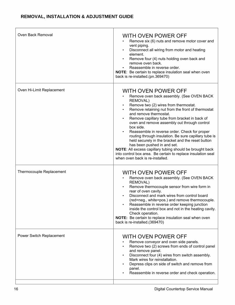
REMOVAL, INSTALLATION & ADJUSTMENT GUIDE
Oven Back Removal
WITH OVEN POWER OFF • Remove six (6) nuts and remove motor cover and
vent piping. • Disconnect all wiring from motor and heating
element. • Remove four (4) nuts holding oven back and
remove oven back. • Reassemble in reverse order.
NOTE: Be certain to replace insulation seal when oven back is re-installed.(pn.369470)
Oven Hi-Limit Replacement
WITH OVEN POWER OFF • Remove oven back assembly. (See OVEN BACK
REMOVAL) • Remove two (2) wires from thermostat. • Remove retaining nut from the front of thermostat
and remove thermostat. • Remove capillary tube from bracket in back of
oven and remove assembly out through control box side.
• Reassemble in reverse order. Check for proper routing through insulation. Be sure capillary tube is held securely in the bracket and the reset button has been pushed in and set.
NOTE: All excess capillary tubing should be brought back into control box area. Be certain to replace insulation seal when oven back is re-installed.
Thermocouple Replacement
WITH OVEN POWER OFF • Remove oven back assembly. (See OVEN BACK
REMOVAL) • Remove thermocouple sensor from wire form in
rear of oven cavity. • Disconnect and mark wires from control board
(red=neg., white=pos.) and remove thermocouple. • Reassemble in reverse order keeping junction
inside the control box and not in the heating cavity. Check operation.
NOTE: Be certain to replace insulation seal when oven back is re-installed.(369470)
Power Switch Replacement
WITH OVEN POWER OFF • Remove conveyor and oven side panels. • Remove two (2) screws from ends of control panel
and remove panel. • Disconnect four (4) wires from switch assembly.
Mark wires for reinstallation. • Depress clips on side of switch and remove from
panel. • Reassemble in reverse order and check operation.
Digital Countertop Service Manual 17
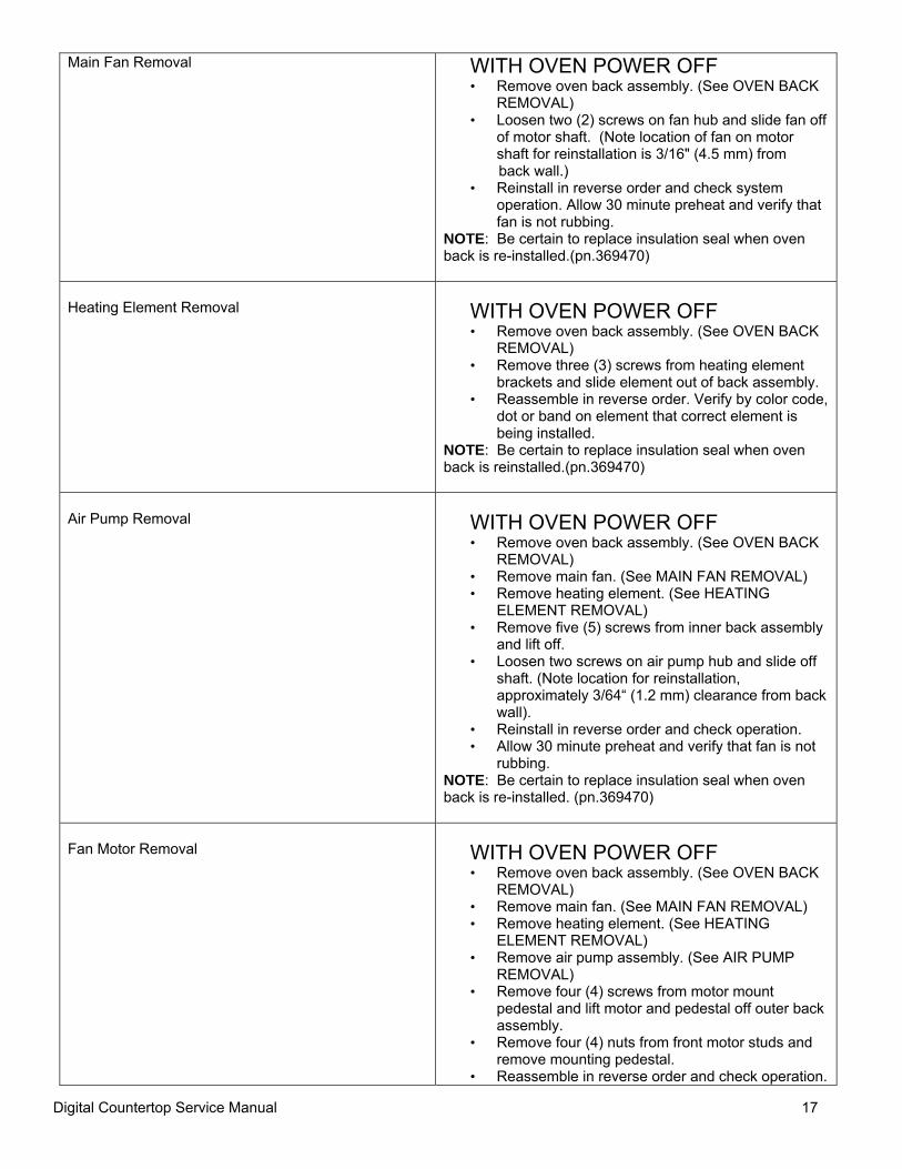
Main Fan Removal
WITH OVEN POWER OFF • Remove oven back assembly. (See OVEN BACK
REMOVAL) • Loosen two (2) screws on fan hub and slide fan off
of motor shaft. (Note location of fan on motor shaft for reinstallation is 3/16" (4.5 mm) from
back wall.) • Reinstall in reverse order and check system
operation. Allow 30 minute preheat and verify that fan is not rubbing.
NOTE: Be certain to replace insulation seal when oven back is re-installed.(pn.369470)
Heating Element Removal
WITH OVEN POWER OFF • Remove oven back assembly. (See OVEN BACK
REMOVAL) • Remove three (3) screws from heating element
brackets and slide element out of back assembly. • Reassemble in reverse order. Verify by color code,
dot or band on element that correct element is being installed.
NOTE: Be certain to replace insulation seal when oven back is reinstalled.(pn.369470)
Air Pump Removal
WITH OVEN POWER OFF • Remove oven back assembly. (See OVEN BACK
REMOVAL) • Remove main fan. (See MAIN FAN REMOVAL) • Remove heating element. (See HEATING
ELEMENT REMOVAL) • Remove five (5) screws from inner back assembly
and lift off. • Loosen two screws on air pump hub and slide off
shaft. (Note location for reinstallation, approximately 3/64“ (1.2 mm) clearance from back wall).
• Reinstall in reverse order and check operation. • Allow 30 minute preheat and verify that fan is not
rubbing. NOTE: Be certain to replace insulation seal when oven back is re-installed. (pn.369470)
Fan Motor Removal
WITH OVEN POWER OFF • Remove oven back assembly. (See OVEN BACK
REMOVAL) • Remove main fan. (See MAIN FAN REMOVAL) • Remove heating element. (See HEATING
ELEMENT REMOVAL) • Remove air pump assembly. (See AIR PUMP
REMOVAL) • Remove four (4) screws from motor mount
pedestal and lift motor and pedestal off outer back assembly.
• Remove four (4) nuts from front motor studs and remove mounting pedestal.
• Reassemble in reverse order and check operation.
Digital Countertop Service Manual 18
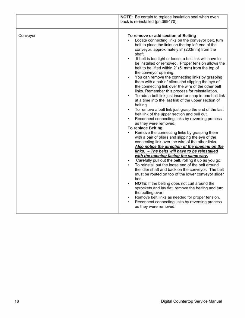
NOTE: Be certain to replace insulation seal when oven back is re-installed (pn.369470).
Conveyor
To remove or add section of Belting • Locate connecting links on the conveyor belt, turn
belt to place the links on the top left end of the conveyor, approximately 8” (203mm) from the shaft.
• If belt is too tight or loose, a belt link will have to be installed or removed. Proper tension allows the belt to be lifted within 2” (51mm) from the top of the conveyor opening.
• You can remove the connecting links by grasping them with a pair of pliers and slipping the eye of the connecting link over the wire of the other belt links. Remember this process for reinstallation.
• To add a belt link just insert or snap in one belt link at a time into the last link of the upper section of belting.
• To remove a belt link just grasp the end of the last belt link of the upper section and pull out.
• Reconnect connecting links by reversing process as they were removed.
To replace Belting • Remove the connecting links by grasping them
with a pair of pliers and slipping the eye of the connecting link over the wire of the other links. Also notice the direction of the opening on the links. – The belts will have to be reinstalled with the opening facing the same way.
• Carefully pull out the belt, rolling it up as you go. • To reinstall put the loose end of the belt around
the idler shaft and back on the conveyor. The belt must be routed on top of the lower conveyor slider bed.
• NOTE: If the belting does not curl around the sprockets and lay flat, remove the belting and turn the belting over.
• Remove belt links as needed for proper tension. • Reconnect connecting links by reversing process
as they were removed.
Digital Countertop Service Manual 19
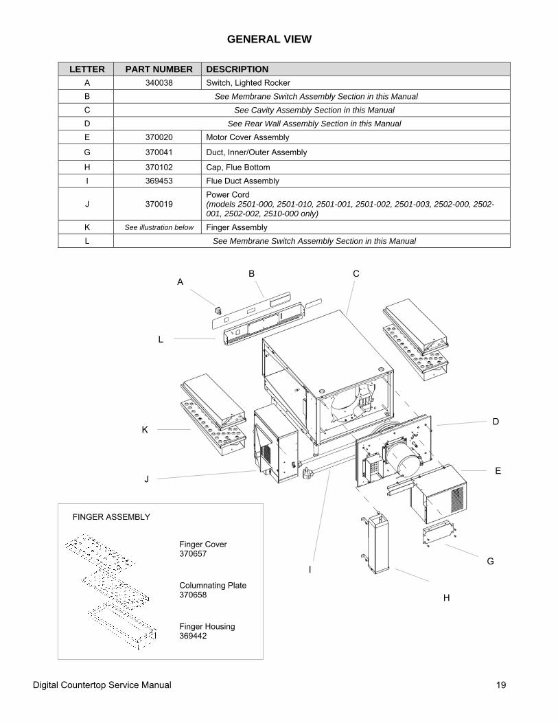
GENERAL VIEW
LETTER PART NUMBER DESCRIPTION A 340038 Switch, Lighted Rocker B See Membrane Switch Assembly Section in this Manual C See Cavity Assembly Section in this Manual D See Rear Wall Assembly Section in this Manual E 370020 Motor Cover Assembly
G 370041 Duct, Inner/Outer Assembly
H 370102 Cap, Flue Bottom I 369453 Flue Duct Assembly
J 370019 Power Cord (models 2501-000, 2501-010, 2501-001, 2501-002, 2501-003, 2502-000, 2502-001, 2502-002, 2510-000 only)
K See illustration below Finger Assembly L See Membrane Switch Assembly Section in this Manual
H
A B C
D
E
G I
J
K
L
Finger Cover 370657
Columnating Plate 370658
Finger Housing 369442
FINGER ASSEMBLY
Digital Countertop Service Manual 20
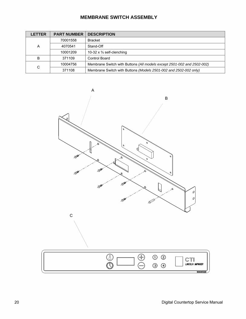
MEMBRANE SWITCH ASSEMBLY
LETTER PART NUMBER DESCRIPTION
A 70001558 Bracket 4070541 Stand-Off
10001209 10-32 x ¾ self-clenching B 371109 Control Board
C 10004756 Membrane Switch with Buttons (All models except 2501-002 and 2502-002) 371108 Membrane Switch with Buttons (Models 2501-002 and 2502-002 only)
A
B
C
Digital Countertop Service Manual 21
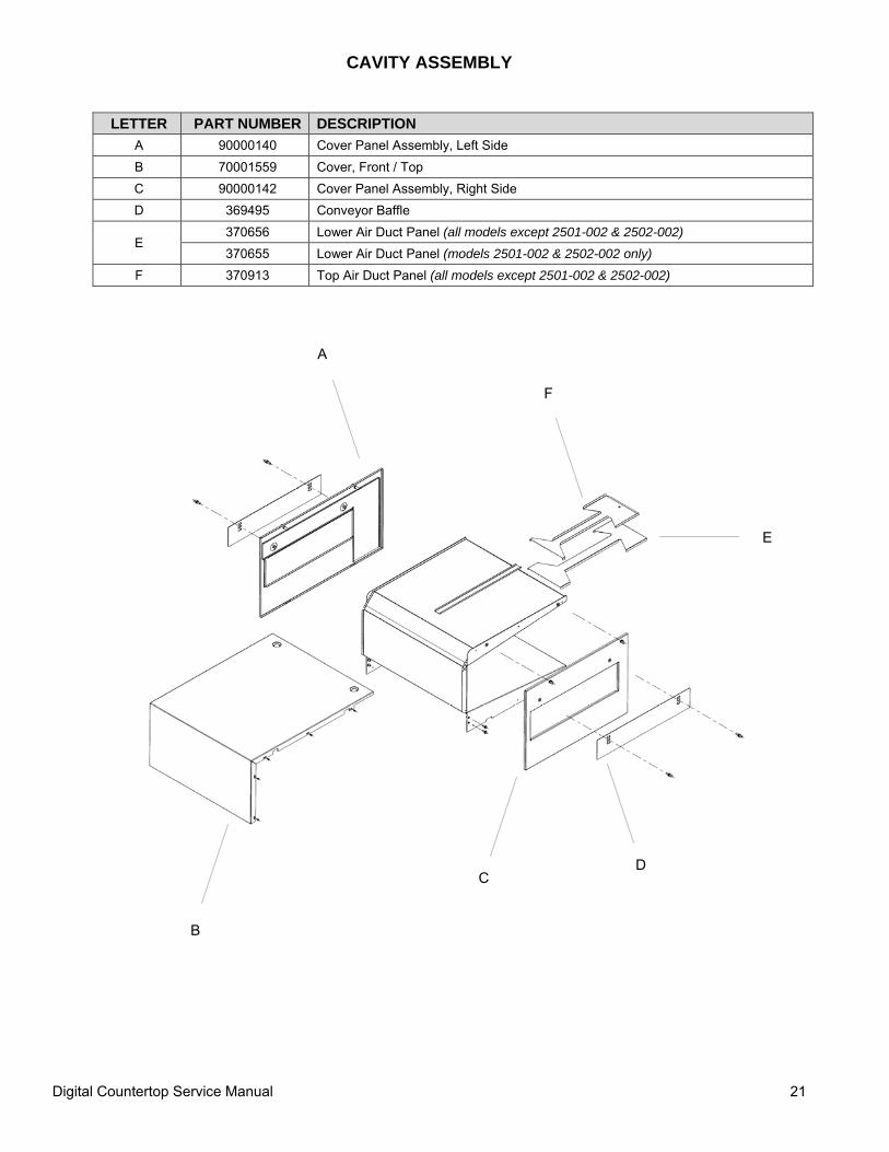
CAVITY ASSEMBLY
LETTER PART NUMBER DESCRIPTION
A 90000140 Cover Panel Assembly, Left Side B 70001559 Cover, Front / Top C 90000142 Cover Panel Assembly, Right Side D 369495 Conveyor Baffle
E 370656 Lower Air Duct Panel (all models except 2501-002 & 2502-002) 370655 Lower Air Duct Panel (models 2501-002 & 2502-002 only)
F 370913 Top Air Duct Panel (all models except 2501-002 & 2502-002)
A
B
C D
E
F
Digital Countertop Service Manual 22
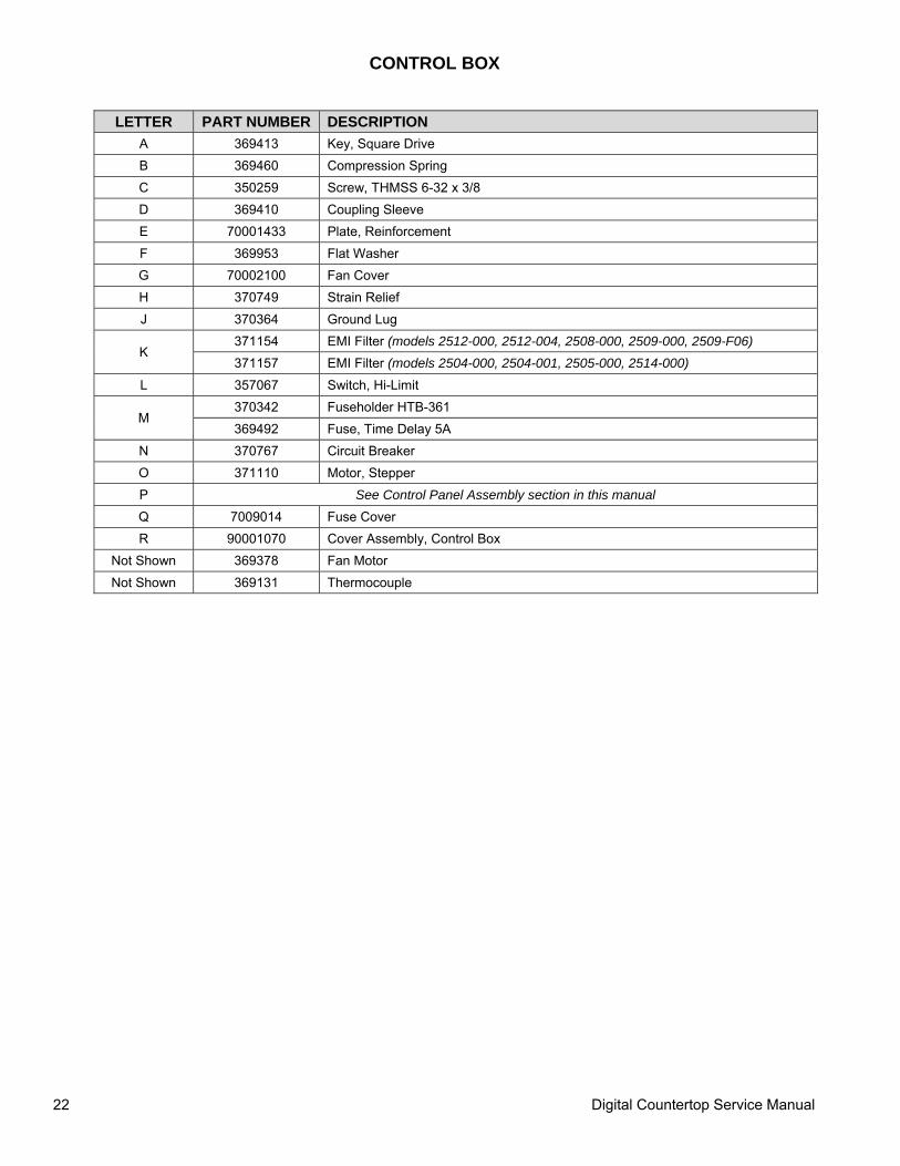
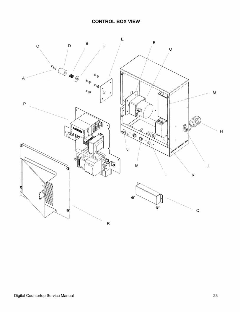
CONTROL BOX
LETTER PART NUMBER DESCRIPTION A 369413 Key, Square Drive B 369460 Compression Spring C 350259 Screw, THMSS 6-32 x 3/8 D 369410 Coupling Sleeve E 70001433 Plate, Reinforcement F 369953 Flat Washer G 70002100 Fan Cover H 370749 Strain Relief J 370364 Ground Lug
K 371154 EMI Filter (models 2512-000, 2512-004, 2508-000, 2509-000, 2509-F06) 371157 EMI Filter (models 2504-000, 2504-001, 2505-000, 2514-000)
L 357067 Switch, Hi-Limit
M 370342 Fuseholder HTB-361 369492 Fuse, Time Delay 5A
N 370767 Circuit Breaker O 371110 Motor, Stepper P See Control Panel Assembly section in this manual Q 7009014 Fuse Cover R 90001070 Cover Assembly, Control Box
Not Shown 369378 Fan Motor Not Shown 369131 Thermocouple
Digital Countertop Service Manual 23
CONTROL BOX VIEW
A
B C D
E
F
G
H
J
K L
M
N
O
E
Q
R
P
Digital Countertop Service Manual 24
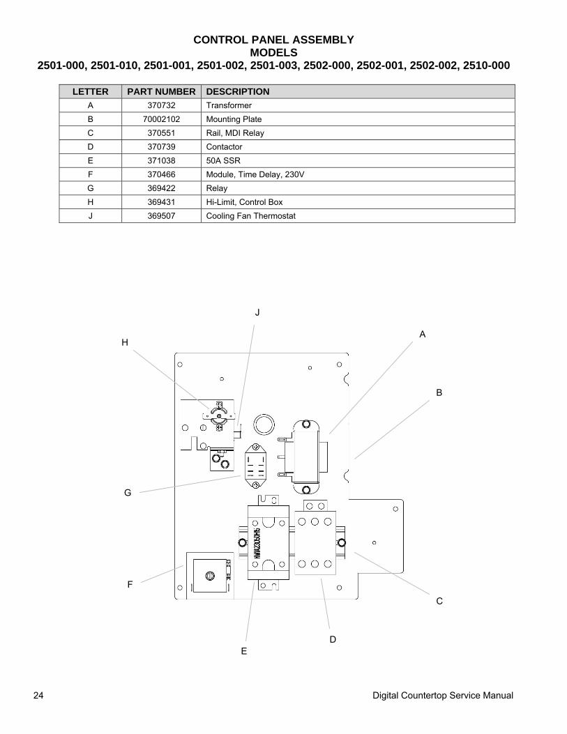
CONTROL PANEL ASSEMBLY MODELS
2501-000, 2501-010, 2501-001, 2501-002, 2501-003, 2502-000, 2502-001, 2502-002, 2510-000
LETTER PART NUMBER DESCRIPTION A 370732 Transformer B 70002102 Mounting Plate C 370551 Rail, MDI Relay D 370739 Contactor E 371038 50A SSR F 370466 Module, Time Delay, 230V G 369422 Relay H 369431 Hi-Limit, Control Box J 369507 Cooling Fan Thermostat
A
B
C
D E
F
G
H
J
Digital Countertop Service Manual 25
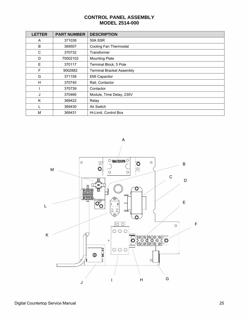
CONTROL PANEL ASSEMBLY MODEL 2514-000
LETTER PART NUMBER DESCRIPTION
A 371038 50A SSR B 369507 Cooling Fan Thermostat C 370732 Transformer D 70002102 Mounting Plate E 370117 Terminal Block, 5 Pole F 9002882 Terminal Bracket Assembly G 371158 EMI Capacitor H 370740 Rail, Contactor I 370739 Contactor J 370466 Module, Time Delay, 230V K 369422 Relay L 369430 Air Switch M 369431 Hi-Limit, Control Box
A
B
D
E
F
G H I J
K
L
M
C
Digital Countertop Service Manual 26
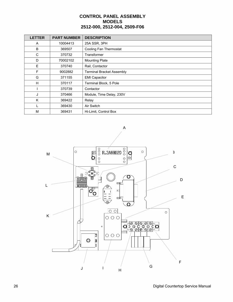
CONTROL PANEL ASSEMBLY MODELS
2512-000, 2512-004, 2509-F06
LETTER PART NUMBER DESCRIPTION A 10004413 25A SSR, 3PH B 369507 Cooling Fan Thermostat C 370732 Transformer D 70002102 Mounting Plate E 370740 Rail, Contactor F 9002882 Terminal Bracket Assembly G 371155 EMI Capacitor H 370117 Terminal Block, 5 Pole I 370739 Contactor J 370466 Module, Time Delay, 230V K 369422 Relay L 369430 Air Switch M 369431 Hi-Limit, Control Box
A
B
D
E
F G
H I J
K
L
C
M
Digital Countertop Service Manual 27
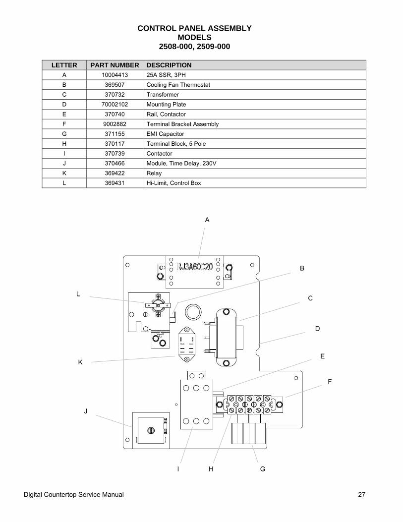
CONTROL PANEL ASSEMBLY MODELS
2508-000, 2509-000
LETTER PART NUMBER DESCRIPTION A 10004413 25A SSR, 3PH B 369507 Cooling Fan Thermostat C 370732 Transformer D 70002102 Mounting Plate E 370740 Rail, Contactor F 9002882 Terminal Bracket Assembly G 371155 EMI Capacitor H 370117 Terminal Block, 5 Pole I 370739 Contactor J 370466 Module, Time Delay, 230V K 369422 Relay L 369431 Hi-Limit, Control Box
A
B
C
D
E
G H I
J
K
L
F
Digital Countertop Service Manual 28
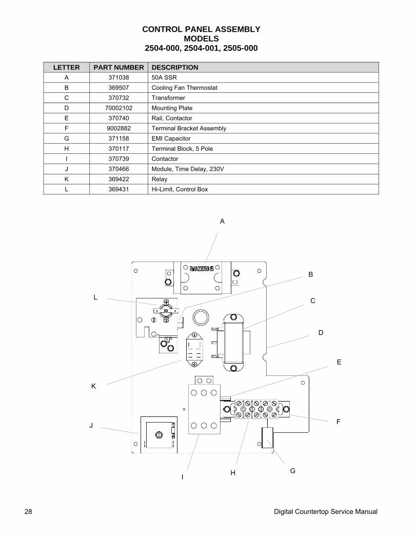
CONTROL PANEL ASSEMBLY MODELS
2504-000, 2504-001, 2505-000
LETTER PART NUMBER DESCRIPTION A 371038 50A SSR B 369507 Cooling Fan Thermostat C 370732 Transformer D 70002102 Mounting Plate E 370740 Rail, Contactor F 9002882 Terminal Bracket Assembly G 371158 EMI Capacitor H 370117 Terminal Block, 5 Pole I 370739 Contactor J 370466 Module, Time Delay, 230V K 369422 Relay L 369431 Hi-Limit, Control Box
A
B
C
D
F
G H I
J
K
L
E

Digital Countertop Service Manual 29
This page intentionally left blank.
Digital Countertop Service Manual 30
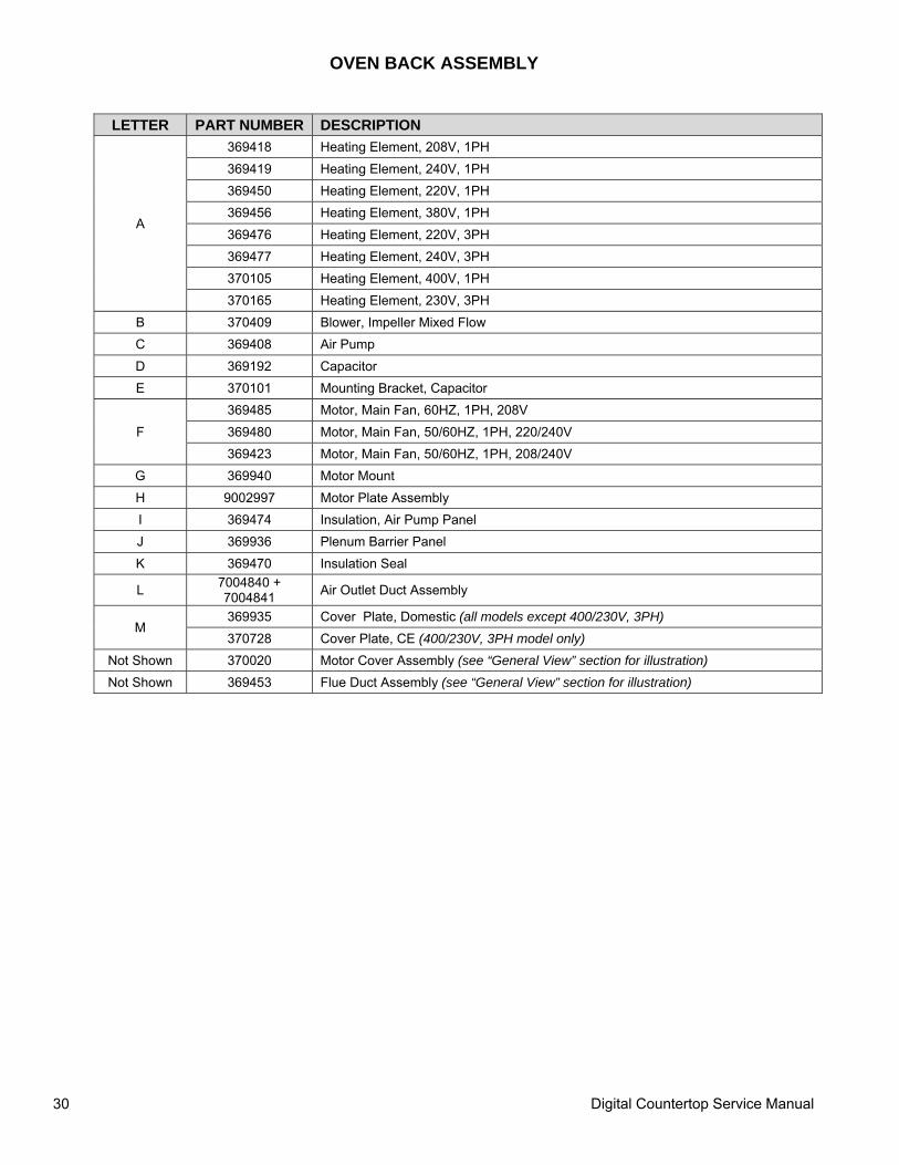
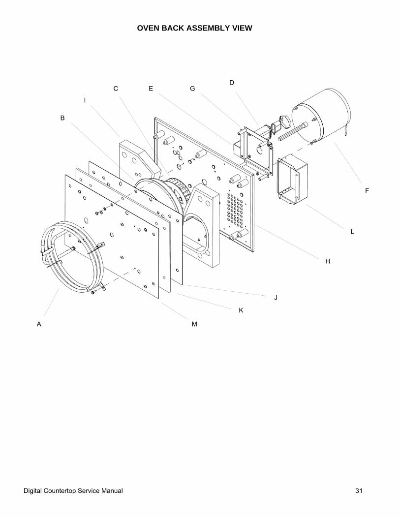
OVEN BACK ASSEMBLY
LETTER PART NUMBER DESCRIPTION
A
369418 Heating Element, 208V, 1PH 369419 Heating Element, 240V, 1PH 369450 Heating Element, 220V, 1PH 369456 Heating Element, 380V, 1PH 369476 Heating Element, 220V, 3PH 369477 Heating Element, 240V, 3PH 370105 Heating Element, 400V, 1PH 370165 Heating Element, 230V, 3PH
B 370409 Blower, Impeller Mixed Flow C 369408 Air Pump D 369192 Capacitor E 370101 Mounting Bracket, Capacitor
F 369485 Motor, Main Fan, 60HZ, 1PH, 208V 369480 Motor, Main Fan, 50/60HZ, 1PH, 220/240V 369423 Motor, Main Fan, 50/60HZ, 1PH, 208/240V
G 369940 Motor Mount H 9002997 Motor Plate Assembly I 369474 Insulation, Air Pump Panel J 369936 Plenum Barrier Panel K 369470 Insulation Seal
L 7004840 + 7004841 Air Outlet Duct Assembly
M 369935 Cover Plate, Domestic (all models except 400/230V, 3PH) 370728 Cover Plate, CE (400/230V, 3PH model only)
Not Shown 370020 Motor Cover Assembly (see “General View” section for illustration) Not Shown 369453 Flue Duct Assembly (see “General View” section for illustration)
Digital Countertop Service Manual 31
OVEN BACK ASSEMBLY VIEW
A
B
C D
G
F
E
H
I
J
K
M
L
Digital Countertop Service Manual 32
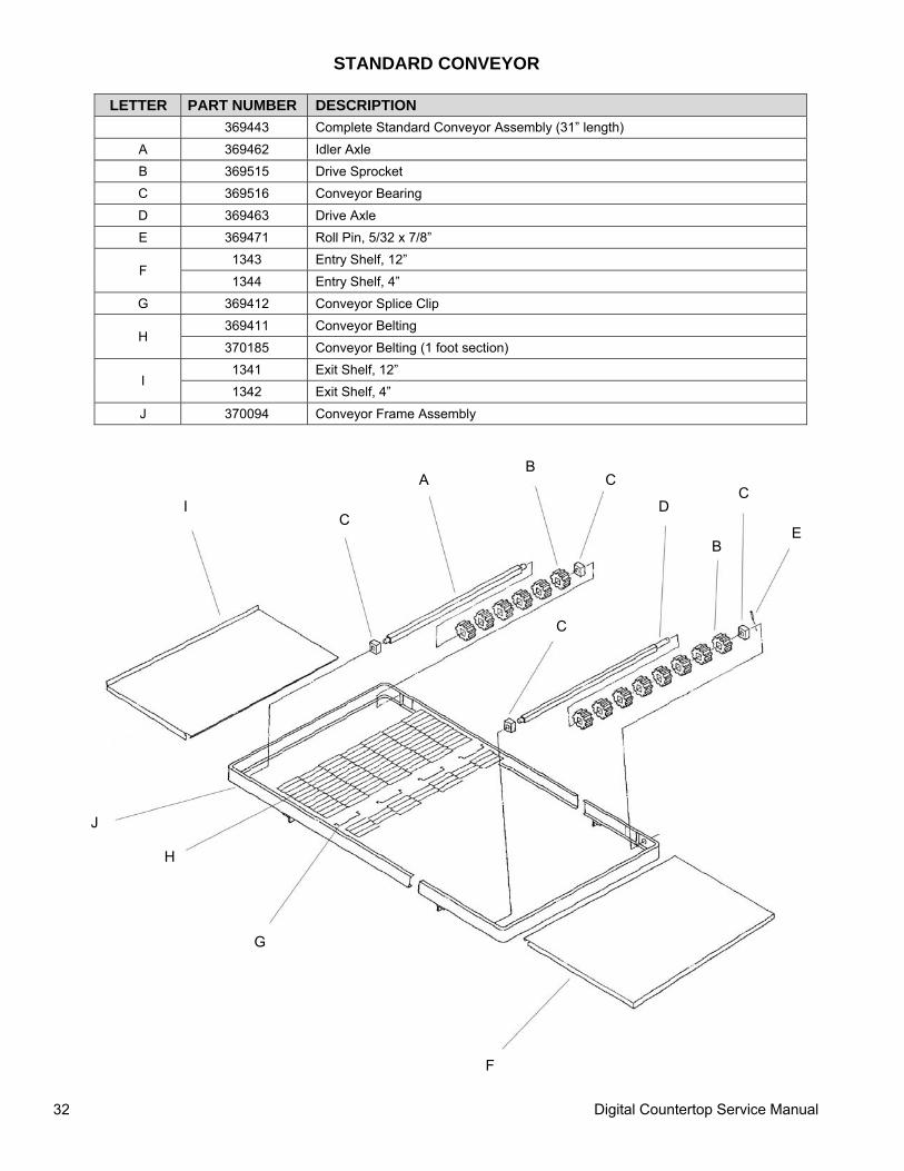
STANDARD CONVEYOR
LETTER PART NUMBER DESCRIPTION 369443 Complete Standard Conveyor Assembly (31” length)
A 369462 Idler Axle B 369515 Drive Sprocket C 369516 Conveyor Bearing D 369463 Drive Axle E 369471 Roll Pin, 5/32 x 7/8”
F 1343 Entry Shelf, 12” 1344 Entry Shelf, 4”
G 369412 Conveyor Splice Clip
H 369411 Conveyor Belting 370185 Conveyor Belting (1 foot section)
I 1341 Exit Shelf, 12” 1342 Exit Shelf, 4”
J 370094 Conveyor Frame Assembly
A B
C
D
B
C
E
C
C I
J
H
G
F
Digital Countertop Service Manual 33
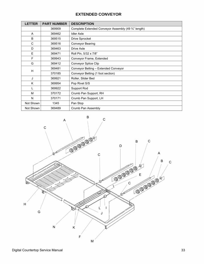
EXTENDED CONVEYOR
LETTER PART NUMBER DESCRIPTION 369909 Complete Extended Conveyor Assembly (49 ¾” length)
A 369462 Idler Axle B 369515 Drive Sprocket C 369516 Conveyor Bearing D 369463 Drive Axle E 369471 Roll Pin, 5/32 x 7/8” F 369943 Conveyor Frame, Extended G 369412 Conveyor Splice Clip
H 369481 Conveyor Belting – Extended Conveyor 370185 Conveyor Belting (1 foot section)
J 369921 Roller, Slider Bed K 369954 Pop Rivet S/S L 369922 Support Rod M 370172 Crumb Pan Support, RH N 370171 Crumb Pan Support, LH
Not Shown 1345 Pan Stop Not Shown 369489 Crumb Pan Assembly
C
A B
C
C
D B C
A
B C
E
C
I L J
M F
K N
G
H
Digital Countertop Service Manual 34
This page intentionally left blank.
Digital Countertop Service Manual 35
This page intentionally left blank.

Digital Countertop Service Manual 36